OE NextUp - Manual V1.1 - Orient Express NextUp Manual V1.1… · Orient Express Racing 28 Grand...
12
NEXTUP CONTROLLER INSTALLATION MANUAL - REV. B, VERSION 1.1 1 Nextup Manual OFF-ROAD USE ONLY ©2010 Biperformance Development Corp. CONTENTS INTRODUCTION 1 STEP ONE – Controller and Wiring 2 STEP TWO – Setup and Tuning 8 SUGGESTED STARTING VALUES 11 TROUBLESHOOTING 11 CONTACT INFORMATION & DISCLAIMER 12 INTRODUCTION This installation manual explains how to install a Nextup Controller onto a motorcycle. The work should be performed by a trained mechanic working in a shop environment. If the installer encounters any problems along the way they should review the troubleshooting section and then contact the company for support if the problem can not be resolved. The Nextup Controller is a transmission control system for motorcycle engines. A bike equipped with a Nextup Controller should be able to upshift using a button or quickshifter at full throttle. Best results obtained when shifting in upper RPM range.
Transcript of OE NextUp - Manual V1.1 - Orient Express NextUp Manual V1.1… · Orient Express Racing 28 Grand...

NEXTUP CONTROLLER INSTALLATION MANUAL - REV. B, VERSION 1.1
1 Nextup Manual OFF-ROAD USE ONLY ©2010 Biperformance Development Corp.
CONTENTS
INTRODUCTION 1
STEP ONE – Controller and Wiring 2
STEP TWO – Setup and Tuning 8
SUGGESTED STARTING VALUES 11
TROUBLESHOOTING 11
CONTACT INFORMATION & DISCLAIMER 12
INTRODUCTION
This installation manual explains how to install a Nextup Controller onto a
motorcycle. The work should be performed by a trained mechanic working in
a shop environment. If the installer encounters any problems along the way
they should review the troubleshooting section and then contact the company
for support if the problem can not be resolved.
The Nextup Controller is a transmission control system for motorcycle
engines. A bike equipped with a Nextup Controller should be able to upshift
using a button or quickshifter at full throttle. Best results obtained when
shifting in upper RPM range.

NEXTUP CONTROLLER INSTALLATION MANUAL - REV. B, VERSION 1.1
2 Nextup Manual OFF-ROAD USE ONLY ©2010 Biperformance Development Corp.
STEP ONE -
Controller and Wiring
It is recommended that the Nextup Controller be installed using a Nextup wiring
harness. When installing the Nextup Controller with a Nextup wiring harness use
the installation manual specific to the wiring harness. Otherwise follow the
general instructions below:
Tools and Supplies Needed for Installation Without a Wiring Harness:
• Wire cutter
• Wire stripper
• Insulated crimper
• Insulated butt splices, ¼” ring terminals, ¼” blade terminals, #4 spade
connectors, and wire taps
• Multi-meter
• Wire (18 AWG minimum gauge)
• Plastic tie straps
Note: Solder joints can be used in place of butt splices and wire taps.
1. Securely mount the controller in a dry place away from heat sources.
2. Determine whether the motorcycle wiring is type 1 (Figure 1-1) or type 2
(Figure 1-2). Refer to the motorcycles wiring diagram or test the OEM horn
connector with the ignition ON (Figure 1-3). Type 1 wiring can be verified by
measuring 12 volts on one of the terminals. Note the 12 volt wire colour. Type
2 wiring can be verified by measuring 12 volts on one of the terminals only
when the horn button is pressed.

NEXTUP CONTROLLER INSTALLATION MANUAL - REV. B, VERSION 1.1
3 Nextup Manual OFF-ROAD USE ONLY ©2010 Biperformance Development Corp.
Figure 1 - 1 : Type 1 Wiring
Figure 1 - 2 : Type 2 Wiring
Figure 1 - 3 : Test for Wiring Type
3. Turn the ignition off. For type 1 wiring, make the power and ground
connections as per wiring diagram (Figure 1-4). For type 2 wiring, make the

NEXTUP CONTROLLER INSTALLATION MANUAL - REV. B, VERSION 1.1
4 Nextup Manual OFF-ROAD USE ONLY ©2010 Biperformance Development Corp.
power and ground connections as per the wiring diagram (Figure 1-5). Pull
wire to the controller, cut, strip, and crimp on the spade connectors.
Figure 1 - 4 : Type 1 Power and Ground Connections
Figure 1 - 5 : Type 2 Power and Ground Connections
4. Turn the motor cycle ignition ON. Verify that both LED bar graphs are lit on
the controller. DO NOT PROCEED TO THE NEXT STEP UNTIL POWER
AND GROUND CONNECTIONS ARE VERIFIED.
NEXTUP CONTROLLER INSTALLATION MANUAL - REV. B, VERSION 1.1
5 Nextup Manual OFF-ROAD USE ONLY ©2010 Biperformance Development Corp.
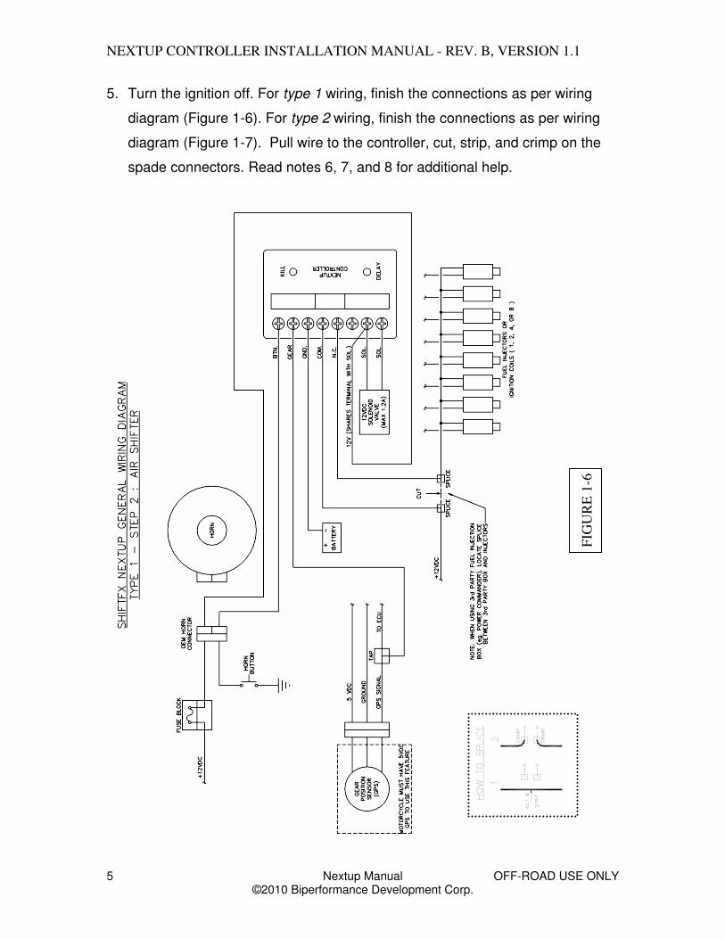
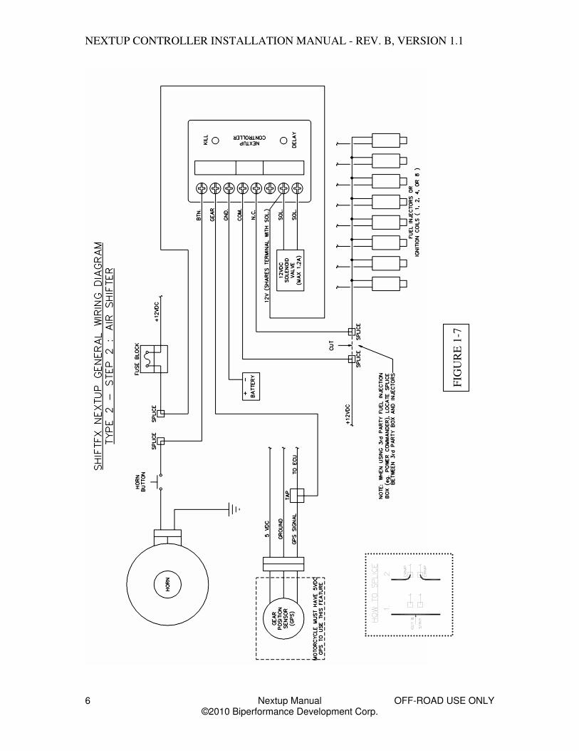
5. Turn the ignition off. For type 1 wiring, finish the connections as per wiring
diagram (Figure 1-6). For type 2 wiring, finish the connections as per wiring
diagram (Figure 1-7). Pull wire to the controller, cut, strip, and crimp on the
spade connectors. Read notes 6, 7, and 8 for additional help.
FIG
UR
E 1
-6
NEXTUP CONTROLLER INSTALLATION MANUAL - REV. B, VERSION 1.1
6 Nextup Manual OFF-ROAD USE ONLY ©2010 Biperformance Development Corp.
FIG
UR
E 1
-7
NEXTUP CONTROLLER INSTALLATION MANUAL - REV. B, VERSION 1.1
7 Nextup Manual OFF-ROAD USE ONLY ©2010 Biperformance Development Corp.
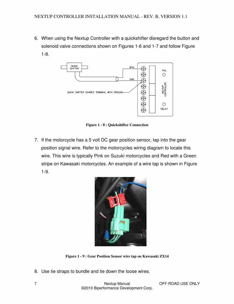
6. When using the Nextup Controller with a quickshifter disregard the button and
solenoid valve connections shown on Figures 1-6 and 1-7 and follow Figure
1-8.
Figure 1 - 8 : Quickshifter Connection
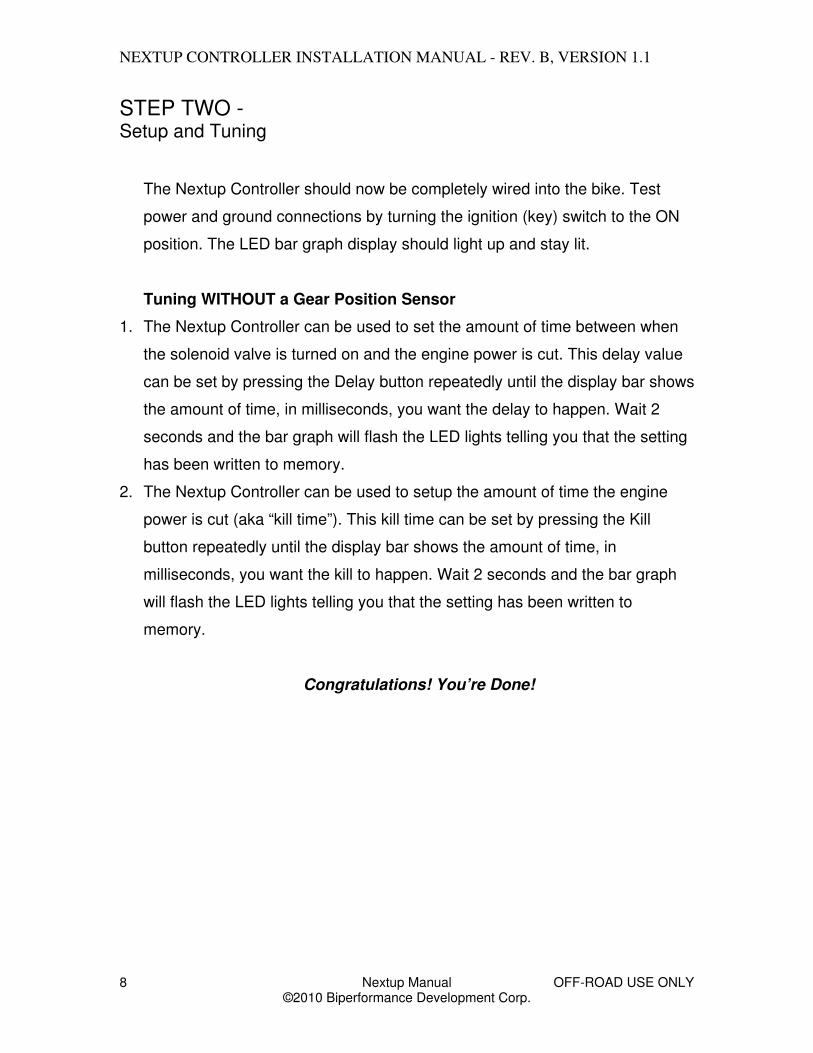
7. If the motorcycle has a 5 volt DC gear position sensor, tap into the gear
position signal wire. Refer to the motorcycles wiring diagram to locate this
wire. This wire is typically Pink on Suzuki motorcycles and Red with a Green
stripe on Kawasaki motorcycles. An example of a wire tap is shown in Figure
1-9.
Figure 1 - 9 : Gear Position Sensor wire tap on Kawasaki ZX14
8. Use tie straps to bundle and tie down the loose wires.
NEXTUP CONTROLLER INSTALLATION MANUAL - REV. B, VERSION 1.1
8 Nextup Manual OFF-ROAD USE ONLY ©2010 Biperformance Development Corp.
STEP TWO - Setup and Tuning
The Nextup Controller should now be completely wired into the bike. Test
power and ground connections by turning the ignition (key) switch to the ON
position. The LED bar graph display should light up and stay lit.
Tuning WITHOUT a Gear Position Sensor
1. The Nextup Controller can be used to set the amount of time between when
the solenoid valve is turned on and the engine power is cut. This delay value
can be set by pressing the Delay button repeatedly until the display bar shows
the amount of time, in milliseconds, you want the delay to happen. Wait 2
seconds and the bar graph will flash the LED lights telling you that the setting
has been written to memory.
2. The Nextup Controller can be used to setup the amount of time the engine
power is cut (aka “kill time”). This kill time can be set by pressing the Kill
button repeatedly until the display bar shows the amount of time, in
milliseconds, you want the kill to happen. Wait 2 seconds and the bar graph
will flash the LED lights telling you that the setting has been written to
memory.
Congratulations! You’re Done!

NEXTUP CONTROLLER INSTALLATION MANUAL - REV. B, VERSION 1.1
9 Nextup Manual OFF-ROAD USE ONLY ©2010 Biperformance Development Corp.
Tuning WITH a Gear Position Sensor
1. Turn both the ignition (key) switch AND the engine stop switch to the ON
position.
2. IMPORTANT – the Nextup controller must be configured to work with your
motorcycles gear position sensor. Motorcycles such as Suzuki use a
STANDARD gear position sensor that outputs lower voltage values at lower
gear positions. Some motorcycles, such as Kawasaki, use a REVERSE gear
position sensor that outputs higher voltage values at lower gear positions. If
you do not know what type of gear position sensor you have use a multimeter
connected between the Gear and Ground terminal screws and compare the
voltage reading in 1st gear and 2nd gear. If the 1st gear value is lower than the
2nd gear value you have a STANDARD gear position sensor.
Refer to Figure 2-1 when configuring the Nextup controller. Reset your
Nextup controller by holding both the Delay and Kill buttons until the LED bars
turn OFF (takes about 5 seconds).
a) Setup the Nextup controller for the STANDARD (Suzuki) gear position
sensor by releasing the Delay button first. The Nextup controller will
confirm this by flashing the Delay bar graph.
b) Setup the Nextup controller for REVERSE (Kawasaki) gear position
sensor by releasing the Kill button first. The Nextup controller will
confirm this by flashing the Kill bar graph.
The Nextup controller is now configured.

NEXTUP CONTROLLER INSTALLATION MANUAL - REV. B, VERSION 1.1
10 Nextup Manual OFF-ROAD USE ONLY ©2010 Biperformance Development Corp.
Figure 2 - 1
3. Place the motorcycle into 1st gear.
4. The delay value is the amount of time between when the solenoid valve is
turned on and the engine power is cut. Set the delay value by pressing the
Delay button repeatedly until the display bar shows the amount of time, in
milliseconds, you want the delay to happen. Wait 2 seconds and the bar
graph will flash the LED lights telling you that the setting has been written to
memory.
5. The kill time is the amount of time the engine power is cut during an upshift.
This kill time can be set by pressing the Kill button repeatedly until the display
bar shows the amount of time, in milliseconds, you want the kill to happen.
Wait 2 seconds and the bar graph will flash the LED lights telling you that the
setting has been written to memory.
6. Repeat steps 4 and 5 for gear positions 2, 3, 4, and 5. It is OK to leave delay
and kill times unchanged for two or more gear positions.
7. Once complete, go back through the gears and confirm the LED bar graph
displays the correct timing for each gear. Make changes as needed.
Congratulations! You’re Done!
Release the Kill button first to configure the motorcycle for REVERSE gear position sensors.
Release the Delay button first to configure the motorcycle for STANDARD gear position sensors.

NEXTUP CONTROLLER INSTALLATION MANUAL - REV. B, VERSION 1.1
11 Nextup Manual OFF-ROAD USE ONLY ©2010 Biperformance Development Corp.
SUGGESTED STARTING VALUES
Engine Setup
Naturally Aspirated Boosted / Sprayed
Delay 10 – 20 ms 10 – 20 ms
1st Gear Kill 40 – 60 ms 60 – 80 ms
2nd Gear Kill 30 – 50 ms 50 – 60 ms
3rd – 5th Gear Kill 30 – 40 ms 40 – 60 ms
When using a quick shifter, the Delay value can be tuned to vary the amount of preloading done by the foot before the power cut happens. For best results set the Delay value between 0 – 20 ms. TROUBLESHOOTING The following is a list of trouble signs and possible solutions:
Controller does not light up
• Blown Fuse - Replace with one of the same rating.
• Poor ground connection – Check grounding circuit.
• Ignition in OFF position – Turn ignition ON.
Controller unresponsive when Upshift button pressed.
• Bad button wiring – Ensure the button terminal is being
grounded when the Upshift button is pressed.
Controller clicks during Upshift but the solenoid valve does not open.
• Valve draws too much current – Use valve rated at 1.2 A
(14.4W) of power or less.
NEXTUP CONTROLLER INSTALLATION MANUAL - REV. B, VERSION 1.1
12 Nextup Manual OFF-ROAD USE ONLY ©2010 Biperformance Development Corp.
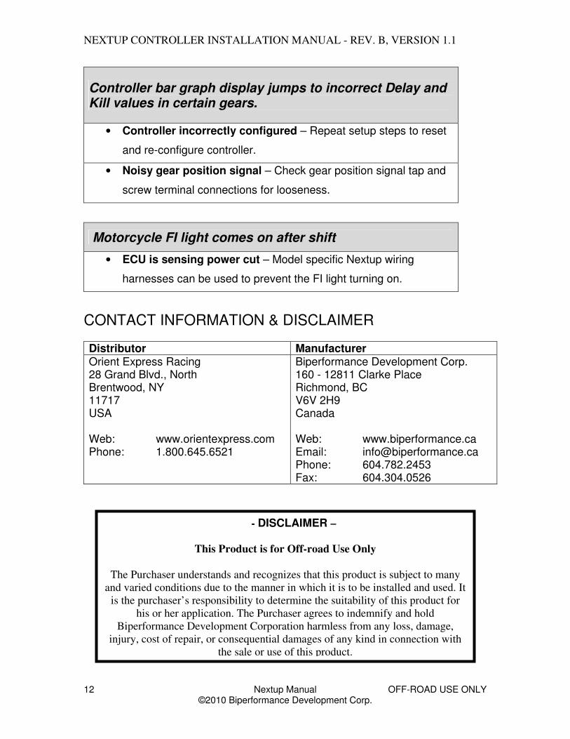
Controller bar graph display jumps to incorrect Delay and Kill values in certain gears.
• Controller incorrectly configured – Repeat setup steps to reset
and re-configure controller.
• Noisy gear position signal – Check gear position signal tap and
screw terminal connections for looseness.
Motorcycle FI light comes on after shift
• ECU is sensing power cut – Model specific Nextup wiring
harnesses can be used to prevent the FI light turning on.
CONTACT INFORMATION & DISCLAIMER Distributor Manufacturer Orient Express Racing 28 Grand Blvd., North Brentwood, NY 11717 USA Web: www.orientexpress.com Phone: 1.800.645.6521
Biperformance Development Corp. 160 - 12811 Clarke Place Richmond, BC V6V 2H9 Canada Web: www.biperformance.ca Email: [email protected] Phone: 604.782.2453 Fax: 604.304.0526
- DISCLAIMER –
This Product is for Off-road Use Only
The Purchaser understands and recognizes that this product is subject to many
and varied conditions due to the manner in which it is to be installed and used. It
is the purchaser’s responsibility to determine the suitability of this product for
his or her application. The Purchaser agrees to indemnify and hold
Biperformance Development Corporation harmless from any loss, damage,
injury, cost of repair, or consequential damages of any kind in connection with
the sale or use of this product.