O/CH ratio on carbon
12
Steam reforming of CH 4 at low temperature on Ni/ ZrO 2 catalyst: Effect of H 2 O/CH 4 ratio on carbon deposition Qing Zhao a , Ye Wang b , Yannan Wang a , Li Li a , Wenqing Zeng b , Guiying Li a,** , Changwei Hu a,b,* a Key Laboratory of Green Chemistry and Technology, Ministry of Education, College of Chemistry, Sichuan University, Chengdu, Sichuan, 610065, PR China b College of Chemical Engineering, Sichuan University, Chengdu, Sichuan 610065, PR China highlights graphical abstract When H 2 O/CH 4 ¼ 2, Ni/ZrO 2 exhibited the highest CH 4 conver- sion (46.8%) at 550 C. Polymer carbon and fiber carbon both formed at low H 2 O/CH 4 ratio(1, 2, 3). Only polymer carbon formed at high H 2 O/CH 4 ratio(5, 10). Easy to removal polymer carbon(C 1 ) covered the active site at low H 2 O/CH 4 ratio. The excess water would lead to the conversion of Ni 0 to Ni(OH) 2 . article info Article history: Received 22 January 2020 Received in revised form 10 March 2020 Accepted 16 March 2020 Available online 11 April 2020 Keywords: Methane steam reforming abstract In present work, the H 2 O/CH 4 on carbon deposition in SRM reaction over Ni/ZrO 2 was studied. Prepared by impregnation, the catalysts were characterized by TEM, XPS, H 2 -TPR, TG-DSC- MS, Raman, and XRD. The results showed that when H 2 O/CH 4 ¼ 2 with GHSV of 14460 h 1 , the highest CH 4 conversion (46.8%) was achieved on the Ni/ZrO 2 catalyst at 550 C. This was due to the relatively high surface content of Ni 0 (27%) species and the formation of easy removal polymer carbon (C 1 ). When the H 2 O/CH 4 was 1, a large amount of difficult to remove fiber carbon (C 2 ) formed and polymer carbon would wrap around the catalyst to reduce its activity. However, excess water might promote surface reconstruction by converting Ni 0 to * Corresponding author. Key Laboratory of Green Chemistry and Technology, Ministry of Education, College of Chemistry, Sichuan University, Chengdu, Sichuan, 610065, PR China. ** Corresponding author. E-mail addresses: [email protected] (G. Li), [email protected] (C. Hu). Available online at www.sciencedirect.com ScienceDirect journal homepage: www.elsevier.com/locate/he international journal of hydrogen energy 45 (2020) 14281 e14292 https://doi.org/10.1016/j.ijhydene.2020.03.112 0360-3199/© 2020 Hydrogen Energy Publications LLC. Published by Elsevier Ltd. All rights reserved.
Transcript of O/CH ratio on carbon

ww.sciencedirect.com
i n t e r n a t i o n a l j o u r n a l o f h y d r o g e n en e r g y 4 5 ( 2 0 2 0 ) 1 4 2 8 1e1 4 2 9 2
Available online at w
ScienceDirect
journal homepage: www.elsevier .com/locate/he
Steam reforming of CH4 at low temperature on Ni/ZrO2 catalyst: Effect of H2O/CH4 ratio on carbondeposition
Qing Zhao a, Ye Wang b, Yannan Wang a, Li Li a, Wenqing Zeng b,Guiying Li a,**, Changwei Hu a,b,*
a Key Laboratory of Green Chemistry and Technology, Ministry of Education, College of Chemistry, Sichuan
University, Chengdu, Sichuan, 610065, PR Chinab College of Chemical Engineering, Sichuan University, Chengdu, Sichuan 610065, PR China
h i g h l i g h t s
* Corresponding author. Key Laboratory ofUniversity, Chengdu, Sichuan, 610065, PR Ch** Corresponding author.
E-mail addresses: [email protected] (Ghttps://doi.org/10.1016/j.ijhydene.2020.03.1120360-3199/© 2020 Hydrogen Energy Publicati
g r a p h i c a l a b s t r a c t
� When H2O/CH4 ¼ 2, Ni/ZrO2
exhibited the highest CH4 conver-
sion (46.8%) at 550 �C.
� Polymer carbon and fiber carbon
both formed at low H2O/CH4
ratio(1, 2, 3).
� Only polymer carbon formed at
high H2O/CH4 ratio(5, 10).
� Easy to removal polymer
carbon(C1) covered the active site
at low H2O/CH4 ratio.
� The excess water would lead to the
conversion of Ni0 to Ni(OH)2.
a r t i c l e i n f o
Article history:
Received 22 January 2020
Received in revised form
10 March 2020
Accepted 16 March 2020
Available online 11 April 2020
Keywords:
Methane steam reforming
a b s t r a c t
In presentwork, theH2O/CH4oncarbondeposition inSRMreaction overNi/ZrO2was studied.
Prepared by impregnation, the catalysts were characterized by TEM, XPS, H2-TPR, TG-DSC-
MS, Raman, and XRD. The results showed that when H2O/CH4 ¼ 2 with GHSV of 14460 h�1,
the highest CH4 conversion (46.8%) was achieved on the Ni/ZrO2 catalyst at 550 �C. This was
due to the relatively high surface content of Ni0 (27%) species and the formation of easy
removal polymer carbon (C1).When the H2O/CH4was 1, a large amount of difficult to remove
fiber carbon (C2) formed and polymer carbon would wrap around the catalyst to reduce its
activity. However, excess water might promote surface reconstruction by converting Ni0 to
Green Chemistry and Technology, Ministry of Education, College of Chemistry, Sichuanina.
. Li), [email protected] (C. Hu).
ons LLC. Published by Elsevier Ltd. All rights reserved.

i n t e rn a t i o n a l j o u r n a l o f h y d r o g e n en e r g y 4 5 ( 2 0 2 0 ) 1 4 2 8 1e1 4 2 9 214282
Carbon deposition
Nickel
Zirconia
Low temperature
Ni(OH)2, which reduced the surface Ni0 content and then inhibited the catalytic activity,
while the amount of carbon deposited, especially C2, reduced significantly.
© 2020 Hydrogen Energy Publications LLC. Published by Elsevier Ltd. All rights reserved.
Introduction
Energy shortages and environmental pollution have become
bottlenecks restricting the development of world economy. In
order to reduce energy consumption and alleviate urban
pollution, fuel cells are developing rapidly in recent years. As
an alternative to fossil fuels, hydrogen is becoming more and
more important in the 21st century [1e5]. Especially in the
field of electric vehicles, hydrogen fuel cells play an important
role [6e8], because the chemical reaction of hydrogen in fuel
cells only produce water vapor. In literature, there are four
main ways to produce hydrogen: electrolysis, photolysis,
biological solution and pyrolysis [9e13]. Although methane
partial oxidation, catalytic combustion, and electrolysis
technologies are developing rapidly, steam reforming of nat-
ural gas is still the primary technology for large scale
hydrogen production [14,15]. Methane has the highest
hydrogen to carbon ratio, and is the most suitable hydrogen
production material. To date, there are many methods to
produce H2 from CH4 including steam reforming [2,16e18],
CO2 reforming [19], autothermal reforming [20], and triple
reforming [21]. Compared with other reactions, methane
steam reforming is more widely used in industrial applica-
tions, because it does not require oxygen and the raw mate-
rials are readily available [22]. Because CO water shift reaction
usually occurs simultaneously, a higher hydrogen yield is
obtained [23,24]. One of the limitations of SMR reaction is that
the endothermic reaction needs high temperature, generally
higher than 800 �C [25], which increases the cost of operation.
High reaction temperature will also lead to lower thermal ef-
ficiency of the process. Milder reaction condition could
contribute to low energy cost. M.H. Halabi et al. [26] found that
the main gas products were CO2 and H2 instead of CO at low
temperature (475�Ce725 �C), which was due to the fact that
water gas shift reaction was benefited at low temperature,
implying that higher yield of hydrogen could be achieved.
Therefore, low temperature methane steam reforming is still
of great research significance [27,28].
Another limitation in the pragmatic productionwas carbon
deposition. Especially, using Ni based catalysts, serious car-
bon deposition was often caused by the decomposition of
methane for SRM reaction at low temperature [29e31]. Several
researches on carbon deposition to improve the catalytic ac-
tivity were reported [32e36]. It has been reported that
improving the interaction between metal Ni and the support
could reduce the formation of carbon [37]. Low temperature
SMR reaction over Ni-Ce(1-x)ZrxO2 catalyst could be carried out
under severe conditions (H2O/CH4 ¼ 1) [38]. The mixed
Ce0.8Zr0.2O2 solid had the synergy effect, resulted from high Ni
dispersion, strong thermal resistance, and enhanced
reducibility. 15 wt% Ni-Ce0.8Zr0.2O2 showed the best activity
and stability at 600 �C. Hak-Min Kim et al. [28] investigated the
performance of Ni-Ce0.8Zr0.2O2 catalysts promoted by basic
metal oxide(MgO, CaO, and La2O3) prepared by co-
precipitation method for SMR reaction at low temperature
(600 �C). It was found that the basicity and the interaction
degree of metal with support influence the carbon deposition
[28,39]. Due to its high Ni dispersion, strong basicity, and
metal-support interaction, La-Ni-Ce0.8Zr0.2O2 showed the best
catalytic activity.
Moreover increasing water tomethane ratio can effectively
eliminate some carbon deposition, and the low steam condi-
tions resulted in ineffective carbon gasification [40]. However,
excessive water will lead to the reduction of process thermal
efficiency and the change of product composition. Therefore,
optimization of water to methane ratio can not only obtain
better conversion rate, selectivity and yield, but also effec-
tively inhibit the carbon deposition to a certain extent. At
present, many studies have reported the effects of different
water-methane ratio on catalytic activity [41e43]. Ee Teng Kho
[23] et al. assessed the stability of Ni/TiO2 in SMR at H2O/CH4
ratios of 1e3 and found that the presence of carbon whiskers
at H2O/CH4 ratios of 2 would deactivate the catalyst. Marıa A
[44] proved that the strong interaction between active species
and spinel-like matrix could reduce carbon deposition. Kowit
Lertwittayanon et al. [45] found that encapsulating carbon or
carbon nanotube would form on CaZrO3-modified Ni/a-Al2O3
catalysts. However, there are few studies on the forms of
carbon deposited under different water-methane ratios and
the effect on catalytic activity, which needs more compre-
hensive study.
ZrO2 is a mainly acidic, certain amphoteric character and
reducing metal oxide. Zirconium oxide is widely used in het-
erogeneous catalysis because of its unique properties. Gon-
zalez et al. [46] discussed the variation of nickel metal particle
size under the treatment of H2 or CO with modified nickel/
ZrO2 catalyst. Dominik Eder et al.[47] found that ZrO2 can be
reduced by hydrogen forming oxygen vacancies in the struc-
ture and the presence of water can modify this production.
Furthermore, the catalytic activity of surface oxygen vacancy
of reduced zirconia for the hydrodeoxygenation reaction of
propan-2-ol was also confirmed. Furthermore, it was found
that ZrO2 could change the nature of dry reforming of
methane reactive sites and promote the formation of active
sites for low temperature DRM reaction [48,49]. Because Ni-Si/
ZrO2 catalyst showed good activity in methane low tempera-
ture reforming reaction [48], we applied this catalytic system
to methane steam reforming at low temperature in an
attempt to achieve good catalytic activity. In this context, the
present work was conducted to look into the influence of the
water-methane ratio to carbon deposition on steam methane

i n t e r n a t i o n a l j o u r n a l o f h y d r o g e n en e r g y 4 5 ( 2 0 2 0 ) 1 4 2 8 1e1 4 2 9 2 14283
reforming over Ni/ZrO2 catalyst. Furthermore, the relation-
ship between catalyst structure and catalytic activity caused
by different water-to-methane ratio was further studied. The
states of nickel and deposited carbon over the surface of Ni/
ZrO2 catalyst were studied in detail.
Experimental
Preparation of catalyst
Precipitationmethodwas applied to prepare the ZrO2 support.
Desired amount of Zr(NO3)4▪5H2O (ChengduKelong, China)
was dissolved in deionized water with constant stirring. Then,
NH3$H2Owas added to the above solution to achieve a pH of 9.
After stirring for 2 h, the resultant system was aged for 24 h.
Then, the mixture was filtered and washed three times with
deionized water at room temperature. The obtained sample
was dried at 110 �C for 4 h and then calcined at 600 �C for 5 h to
obtain the ZrO2 support [48].
TheNi/ZrO2 catalyst (5wt%)waspreparedby impregnation.
Ni(NO3)2▪6H2O (ChengduKelong, China, 0.9864 g) is added to
deionized water (20 mL). The ZrO2 support (4 g) was impreg-
nated with the aforesaid aqueous solution for 24 h at room
temperature, then dried at 80 �C for 2h and 110 �C for 4h. After
calcination in flowing air at 600 �C for 5 h (with the heating rate
of 2 �C/min), the Ni/ZrO2 catalyst precursor was obtained.
Catalytic performance test
The low temperature SRM reaction was performed in a stain-
less steel fixed bed reactor with 14 mm inner diameter at at-
mospheric pressure. Firstly, the inert silica filler was added
(44 g, 20e40 mesh), then the mixture of the filler and catalyst
(mcat. ¼ 0.5 g, 20e40 mesh, 0.25 mL; msilica ¼ 20 g, 20e40 mesh,
7.6 mL) were added, and finally silica filler was added to cover
the catalyst bed. The reaction system was heated up to 600 �C(10 �C/min) in argon atmosphere, and then reduced for 1 h in
H2/Ar¼ 1mixture. After cooling to 550 �C in argon atmosphere,
the reaction gases methane (F ¼ 30 mL/min) and H2O were
vented for SMR reaction. While the H2O/CH4 molar ratio was
varied, both methane and argon flow remained at 30 mL/min.
Water was injected through amicro pump and then through a
preheater at 135 �C after gasification of the carburetor at 135 �Cbefore entering the reactor. The effluent from reactor passes
through a condensing device, and a gas chromatography is
used for on-line analysis (TDX - 01 packed column) of the gas
products. The total flow of effluentwasmeasured by onemass
flowmeter. The catalyst and inert filler after reaction are
completely in different form and color, and they can be clearly
distinguished. The inert filler was a gray, clean ball, and the
catalystwas a small particle (black after the reaction). After the
reaction, the catalyst can be picked out one by one.
The conversion of methane (XCH4), the yield of H2 (YH2) and
the content of H2, CO and CO2 (Ci(i¼H2,CO,CO2))were calculated
by the following:
XCH4¼ FCH4; in� FCH4; outFCH4; in
YH2¼ 2FH2; out3ðFCH4; inþ FH2O; inÞ � 100
Ci¼ Fi; outPi¼H2;CO;CO2
Fi; out� 100%
where F represents molar flow rate (mol▪s�1).
Catalyst characterization
The actual Ni loading of the fresh catalyst was determined by
ICP-OES (Agilent, 5100 SVDV). Before the test, the solid catalyst
was dissolved in aqueous sulfuric acid with a volume ratio of
1:2 (water/sulfuric acid concentrated) at 240 �C, and a small
amount of hydrofluoric acid was added until complete
dissolution.
The temperature programmed NH3 adsorption-desorption
experiment was carried out to study acid site distribution and
strength for the catalysts. The sampleswere first purgedwith a
flow rate of 25 mL/min He gas, and then heated to 500 �C at a
rateof 10 �C/min, anda constant temperature at 500�Cwaskept
for 30 min, then cooled down to 50 �C. After switching He to
NH3, the adsorption of NH3 (25 mL/min) was endured for
240min.And thenswitchingNH3 toHe (25mL/min) forpurging,
the temperaturewas raised to 600 �C at a rate of 10 �C/min, and
the NH3 desorption temperature curve was obtained.
The reducibility of calcined samples was obtained by H2
temperature programmed reduction (TPR) method. 0.10g
catalyst was pretreated with Ar flow at 150 �C for 30min. The
TPR experiment was conducted from 50 �C to 950 �C in H2/Ar
(10/90 vol%) flow. TCD detector was used to monitor H2
consumption.
X-ray powder diffraction (XRD) characterization of the
catalysts were performed by an XRD-6100 (SHIMADZU) in-
strument which used Cu Ka radiation under the condition of
40 kV and 25 mA. The test range of diffraction angle (2q) is
from 20� to 80�, the scan speed was 0.3s step�1, and the step
size was 0.03�. Because of the overlap of the XRD profiles of
ZrO2 and Ni, the crystal size of them were obtained by
Scherrer's equation via splitting of the peaks.
Thermogravimetric and mass spectrometry were used to
detect deposited carbon, using NETZSCHTG209F1 instrument.
The test temperature range was from 30 �C to 800 �C (10 �C/min�1) in air/Ar flow (20/60 mL/min�1).
Raman spectra characterization of the used catalysts were
carried out by a LabRAM HR Raman Spectrometer (HORIBA
Jobin Yvon), which used a He-Ne laser source (532 nm). The
Grating was 600 and the filter was D1with the hole of 200mm.
An Tecnai G2 F20 machine Twin instrument Transmission
(0.2 nm resolution) was used to characterize the used cata-
lysts. In the operation, the acceleration voltage was 200Kv.
X-ray photoelectron spectroscopy (XPS) characterization
was performed on AXIS Ultra DLD (KRATOS) spectrometer. All
the results were obtained using monochromated Al Ka radi-
ation with the accelerating power of 25 W. C 1s 284.6eV was
used for calibration, and Lorentz-Gauss ratio (L/G) for peak
splitting was 20%.

Fig. 2 e NH3-TPD profile of Ni/ZrO2 and ZrO2.
i n t e rn a t i o n a l j o u r n a l o f h y d r o g e n en e r g y 4 5 ( 2 0 2 0 ) 1 4 2 8 1e1 4 2 9 214284
Results and discussion
Ni species reduction
Hydrogen temperature programmed reduction was used to
characterize the reduction performance of Ni/ZrO2 precursor
and ZrO2(Fig. 1). There was one main peak on the precursor
oxide reduction curve. It had been reported that the reduction
peak around 400 �C was regarded as bulk NiO species [28].
Therefore, the reduction peak at 420 �C was assigned to bulk
NiO. Since there was only a small amount of zirconia carrier
surface reduction, the other two shoulder peaks at 308 �C and
342 �C were attributed to the reduction of the surface NiO
[50,51]. R. P�erez-Hern�andez [52] et al. found that the TPR pro-
file of the fresh NiO/ZrO2 sample showed a peak at 320 �C.Hyun-Seog Roh et al. [53] found that the broad reduction peak
at about 400 �C was attributed to relatively free NiO weakly
interacting with support and the other peak at 510 �C was
attributed to complex NiO strongly interacting with support.
Evidently, compared with others, the interaction of NiO with
the support over the Ni/ZrO2 catalyst was weak.
Dominik Eder et al. [47] found that oxygen vacancies
formed when zirconia was reduced with hydrogen. At reduc-
tion below 800 K, the oxygen vacancies were most likely
located on the zirconia surface while above 800 K, the for-
mation of bulk vacancies started. Therewere two peaks on the
zirconia reduction curve. Therefore, it could be inferred that
low temperature reduction peak (389 �C) corresponded to
surface oxygen defect (2.37 � 10�2mmol/g) and high temper-
ature reduction peak (627 �C) corresponded to bulk oxygen
defect (3.8 � 10�2mmol/g). Therefore, it will form surface ox-
ygen vacancy and part of bulk oxygen vacancy on zirconia
under hydrogen reduction at 600 �C.
The acidity of support and catalyst
The NH3-TPD results showed that there are two type of acidic
sites with different strengths of acidity (Fig. 2). The low tem-
perature desorption peak (Tm ¼ 50e200 �C) corresponded to
Fig. 1 e H2-TPR profile of Ni/ZrO2 and ZrO2.
the weak acid sites, and the medium temperature peak
(Tm ¼ 200e400 �C) corresponded to the medium acid sites
[54,55]. The strength of acid in both ZrO2 and Ni/ZrO2 samples
were the same, since the NH3 desorption peaks arises at the
same temperature. According to results shown in Fig. 2, the
surface concentration of acid sites decreased, which might be
due to the loading of nickel occupying the acidic sites on the
zirconia surface.
Catalytic activities
XCH4, CCO and CCO2 obtained at 550 �Cwere shown in Fig. 3. The
initial CH4 conversions (at 1 h) were 38.8%, 46.8%, 35.4%, 32.9%
and 24.6%, and the yield of H2 were 12.5%, 14.6%, 11.4%, 10.4%
and 7.5% for the H2O to CH4 ratio of 1, 2, 3, 5, 10, respectively.
When the H2O/CH4 was 2, the highest conversion of methane
was achieved. In terms of the content of CO and CO2, when the
H2O/CH4 was 1, Cco (content of CO) was higher than Cco2
(content of CO2). While the H2O/CH4 went above 1, Cco2 was
higher than Cco. It was apparent that methane steam
reforming reaction (CH4 þ H2O/CO þ 3H2) was carried out to
a greater extent than the CO water vapor shift reaction
(CO þ H2O /CO2 þ H2) [3,56e58] at lower H2O/CH4 ratio, and
increasing the H2O/CH4 was more conducive to the following
water gas shift reaction. In the 12-hour activity test, the cat-
alysts with water-methane ratio of 1, 2 and 3 were gradually
deactivated. When the H2O/CH4 was greater than 3, the cata-
lyst deactivated more rapidly. Especially when the H2O/CH4
was 5 or 10, the catalyst was completely deactivated within 9
hours on steam. The stability of Ni/TiO2 in SMR at H2O/CH4
ratios of 1e3 was studied and it was found that the catalyst
would deactivate at the condition of H2O/CH4 ¼ 2 [23]. As the
steam feed was further increased (H2O/CH4 ¼ 3), the greater
presence of steam was capable of driving effective carbon
gasifification and re-stabilised SRM performance. And 45%
methane conversion could be achieved at 500 �C. S. Gopa-
lakrishnan et al. [59] found that when the reaction was carried
out at H2O/CH4 ¼ 3 on Ni/CeZrO2, H2 production was close to
the thermodynamic upper limit in fact. In industrial applica-
tions, the ratio of water to methanewas usually 2e5 [60,61]. In

Fig. 3 e Catalytic performance of Ni/ZrO2 at 550 �C. (a) CH4 conversion, (b) selectivity of CO and CO2 and (c) yield of H2 at 1st h.
i n t e r n a t i o n a l j o u r n a l o f h y d r o g e n en e r g y 4 5 ( 2 0 2 0 ) 1 4 2 8 1e1 4 2 9 2 14285
the literature, the optimal water-methane ratio was consid-
ered to be 3, while in this paper it was 2. The difference of the
present work from literature might be caused by the different
nature of the support used.
Characterization results
Fig. 4 shows the XRD patterns after reduction and after reac-
tion at different water to methane ratios. The diffraction
Fig. 4 e XRD patterns of Ni/ZrO2 (a) after reduction; after
reaction, reaction condition: (b) H2O/CH4 ¼ 1, (c) H2O/
CH4 ¼ 2, (d) H2O/CH4 ¼ 3, (e) H2O/CH4 ¼ 5, (f) H2O/CH4 ¼ 10.
peaks of nickel and zirconia both existed after reduction and
after reaction. The crystallite size of nickel on Ni/ZrO2 catalyst
after reduction was 24 nm. Furthermore, the crystal size of
metallic Ni after reaction at H2O/CH4 ¼ 1, 2, 3, 5 or 10 were
23 nm, 28 nm, 22 nm, 22 nm, 22 nm respectively (Table 1),
which showed no obvious variation of the size of Ni.When the
H2O/CH4 was 2 or 3, the appearance of the diffraction peak of
carbon indicated that a carbon specieswith better crystallinity
was formed (38 nm and 28 nm). When the H2O/CH4 was 1, 5 or
10, there was no diffraction peak of carbon species on the XRD
profiles. Ee Teng Kho et al. [23] investigated carbon deposition
at different water to methane ratio and found the carbon
peaks (2q ¼ 26.4�, 42.4�) from XRD results while H2O/CH4 ¼ 2,
and carbon whiskers appeared according to the TEM images
on used catalysts which were not present in other ratios. It
could be found that when the H2O/CH4 was 2 or 3, the same
carbon species formed. Furthermore, it was not difficult to
find that when the water-methane ratio was 2 and 3, the
carbon peak appeared in the same position as the XRD results
in the literature [23], and the presence of carbon whiskers
were also found in the TEM image. This might mean that it
was easy to form carbon whiskers at these water-methane
ratios.
TG-DSC-MS characterization was performed to study the
deposited carbon on the used catalyst (Fig. 5). Carbon depo-
sition could be divided into two types based on its different
removal temperature, which included easy removal coke (C1,
Polymeric coke, removable at 400e500 �C) and difficult
removal coke (C2, Fiber carbon, removable at 500e600 �C)[48,62]. Obviously, when the H2O/CH4 was 1e3, there was C1

Table 1 e Amount of carbon deposition on used catalysts, characterized by TG-DSC-MS.
H2O/CH4 Carbon deposition Wtotal (mg.gcat�1 ) Ni crystallite size(nm)b conc.
C1 (peak 1) C2 (peak 2)
Positiona(�C) WC1 (mg.gcat�1 )c Position (�C) WC2 (mg.gcat
�1 ) WC1/WC2
1 471 73 564 78 151 23 0.93
2 436 26 564 21 47 28 1.24
3 434 17 556 11 28 22 1.54
5 471 13 / / 13 22 /
10 436 11 / / 11 22 /
WC1¼Wtotal*Weight Loss ratio(400e500 �C).WC2¼Wtotal*Weight Loss ratio(500e600 �C).a The center position of the peak on CO2 MS single curve.b Calculated from Ni [111] plane by the Scherrer equation.c Calculated from the weight loss of TG (precision: 0.0001 mg).
Fig. 5 e TG-DSC-MS of Ni/ZrO2 catalyst after reaction at different H2O/CH4.
i n t e rn a t i o n a l j o u r n a l o f h y d r o g e n en e r g y 4 5 ( 2 0 2 0 ) 1 4 2 8 1e1 4 2 9 214286
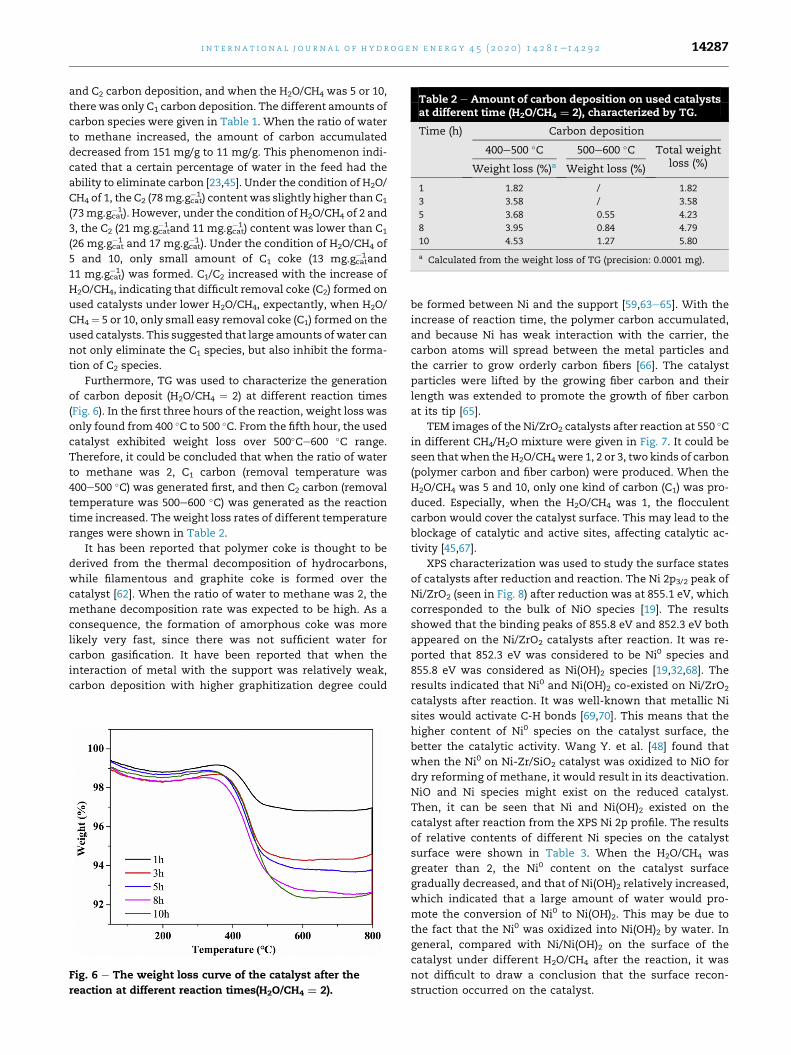
Table 2 e Amount of carbon deposition on used catalystsat different time (H2O/CH4 ¼ 2), characterized by TG.
Time (h) Carbon deposition
400e500 �C 500e600 �C Total weightloss (%)Weight loss (%)a Weight loss (%)
1 1.82 / 1.82
3 3.58 / 3.58
5 3.68 0.55 4.23
8 3.95 0.84 4.79
10 4.53 1.27 5.80
a Calculated from the weight loss of TG (precision: 0.0001 mg).
i n t e r n a t i o n a l j o u r n a l o f h y d r o g e n en e r g y 4 5 ( 2 0 2 0 ) 1 4 2 8 1e1 4 2 9 2 14287
and C2 carbon deposition, and when the H2O/CH4 was 5 or 10,
there was only C1 carbon deposition. The different amounts of
carbon species were given in Table 1. When the ratio of water
to methane increased, the amount of carbon accumulated
decreased from 151 mg/g to 11 mg/g. This phenomenon indi-
cated that a certain percentage of water in the feed had the
ability to eliminate carbon [23,45]. Under the condition of H2O/
CH4 of 1, the C2 (78mg.gcat�1 ) content was slightly higher than C1
(73mg.gcat�1 ). However, under the condition of H2O/CH4 of 2 and
3, the C2 (21 mg.gcat�1and 11 mg.gcat
�1 ) content was lower than C1
(26 mg.gcat�1 and 17 mg.gcat
�1 ). Under the condition of H2O/CH4 of
5 and 10, only small amount of C1 coke (13 mg.gcat�1and
11 mg.gcat�1 ) was formed. C1/C2 increased with the increase of
H2O/CH4, indicating that difficult removal coke (C2) formed on
used catalysts under lower H2O/CH4, expectantly, when H2O/
CH4 ¼ 5 or 10, only small easy removal coke (C1) formed on the
used catalysts. This suggested that large amounts ofwater can
not only eliminate the C1 species, but also inhibit the forma-
tion of C2 species.
Furthermore, TG was used to characterize the generation
of carbon deposit (H2O/CH4 ¼ 2) at different reaction times
(Fig. 6). In the first three hours of the reaction, weight loss was
only found from 400 �C to 500 �C. From the fifth hour, the used
catalyst exhibited weight loss over 500�Ce600 �C range.
Therefore, it could be concluded that when the ratio of water
to methane was 2, C1 carbon (removal temperature was
400e500 �C) was generated first, and then C2 carbon (removal
temperature was 500e600 �C) was generated as the reaction
time increased. The weight loss rates of different temperature
ranges were shown in Table 2.
It has been reported that polymer coke is thought to be
derived from the thermal decomposition of hydrocarbons,
while filamentous and graphite coke is formed over the
catalyst [62]. When the ratio of water to methane was 2, the
methane decomposition rate was expected to be high. As a
consequence, the formation of amorphous coke was more
likely very fast, since there was not sufficient water for
carbon gasification. It have been reported that when the
interaction of metal with the support was relatively weak,
carbon deposition with higher graphitization degree could
Fig. 6 e The weight loss curve of the catalyst after the
reaction at different reaction times(H2O/CH4 ¼ 2).
be formed between Ni and the support [59,63e65]. With the
increase of reaction time, the polymer carbon accumulated,
and because Ni has weak interaction with the carrier, the
carbon atoms will spread between the metal particles and
the carrier to grow orderly carbon fibers [66]. The catalyst
particles were lifted by the growing fiber carbon and their
length was extended to promote the growth of fiber carbon
at its tip [65].
TEM images of the Ni/ZrO2 catalysts after reaction at 550 �Cin different CH4/H2O mixture were given in Fig. 7. It could be
seen that when the H2O/CH4were 1, 2 or 3, two kinds of carbon
(polymer carbon and fiber carbon) were produced. When the
H2O/CH4 was 5 and 10, only one kind of carbon (C1) was pro-
duced. Especially, when the H2O/CH4 was 1, the flocculent
carbon would cover the catalyst surface. This may lead to the
blockage of catalytic and active sites, affecting catalytic ac-
tivity [45,67].
XPS characterization was used to study the surface states
of catalysts after reduction and reaction. The Ni 2p3/2 peak of
Ni/ZrO2 (seen in Fig. 8) after reduction was at 855.1 eV, which
corresponded to the bulk of NiO species [19]. The results
showed that the binding peaks of 855.8 eV and 852.3 eV both
appeared on the Ni/ZrO2 catalysts after reaction. It was re-
ported that 852.3 eV was considered to be Ni0 species and
855.8 eV was considered as Ni(OH)2 species [19,32,68]. The
results indicated that Ni0 and Ni(OH)2 co-existed on Ni/ZrO2
catalysts after reaction. It was well-known that metallic Ni
sites would activate C-H bonds [69,70]. This means that the
higher content of Ni0 species on the catalyst surface, the
better the catalytic activity. Wang Y. et al. [48] found that
when the Ni0 on Ni-Zr/SiO2 catalyst was oxidized to NiO for
dry reforming of methane, it would result in its deactivation.
NiO and Ni species might exist on the reduced catalyst.
Then, it can be seen that Ni and Ni(OH)2 existed on the
catalyst after reaction from the XPS Ni 2p profile. The results
of relative contents of different Ni species on the catalyst
surface were shown in Table 3. When the H2O/CH4 was
greater than 2, the Ni0 content on the catalyst surface
gradually decreased, and that of Ni(OH)2 relatively increased,
which indicated that a large amount of water would pro-
mote the conversion of Ni0 to Ni(OH)2. This may be due to
the fact that the Ni0 was oxidized into Ni(OH)2 by water. In
general, compared with Ni/Ni(OH)2 on the surface of the
catalyst under different H2O/CH4 after the reaction, it was
not difficult to draw a conclusion that the surface recon-
struction occurred on the catalyst.

Fig. 7 e TEM images of the Ni/ZrO2 sample after testing in different CH4/H2O mixture at 550 �C. CH4/H2O¼ (A) 1, (B) 2, (C) 3, (D)
5, (E) 10.
Fig. 8 e Ni 2p binding energy of Ni/ZrO2 (a) after reduction
and after reaction at different H2O/CH4. (b) H2O/CH4 ¼ 1; (c)
H2O/CH4 ¼ 2; (d) H2O/CH4 ¼ 3; (e) H2O/CH4 ¼ 5; (f) H2O/
CH4 ¼ 10.
Table 3 e The XPS data analysis of different nickel and carbon
H2O/CH4 Ni0 Ni(OH)2 or NiO Surface conc. Ni0/N
Area Area
Reduction 1026 3000 0.34
1 930 2570 0.36
2 1076 2843 0.38
3 843 2627 0.32
5 1023 3295 0.31
10 870 3520 0.25
i n t e rn a t i o n a l j o u r n a l o f h y d r o g e n en e r g y 4 5 ( 2 0 2 0 ) 1 4 2 8 1e1 4 2 9 214288
According to the data of C1s XPS (Fig. 9), when the ratio of
water to methane was 1, 2 or 3, there are two different carbon
peaks. Carbon at low binding energy was considered to be
polymer carbon (C1, BE ¼ 284.6eV) overlapped with the
contaminant carbon of the measurement system, while the
carbon at high binding energy was considered to be fiber
carbon (C2, BE ¼ 285.8eV). There were also two kinds of carbon
deposition under the ratio of water to methane below 3 and
there was only polymer carbon with H2O/CH4 ¼ 5, 10 in XPS C
1s results, whichwas consistentwith TG-MS results. In TG-MS
results, the ratio of C1 to C2 increases with the H2O/CH4 ratio
increasing. However, in the XPS results, the ratio of C1 to C2
(see in Table 3) decreased. It could be due to the fact that C1
carbon deposition overlaps with the contaminant carbon
(284.6eV) in XPS instrument, which would greatly affect the
ratio of C1/C2. Thus, the XPS results just give one a qualitative
tendency of carbon species deposited.
The O 1s peak of Ni/ZrO2 (seen in Fig. 10) after reduction
could be deconvoluted to 529.4 eV (lattice oxygen) and 530.8 eV
(surface OH�) [48]. Concerning the Ni/ZrO2 after reaction
under different condition, the peak of Ni(OH)2 (531.2 eV)
species.
i(OH)2 or NiO C2 C1 Surface conc. C1/C2
Area Area
/ / /
2656 6686 2.51
3855 3129 0.82
3654 2802 0.74
3755 / /
3643 / /

Fig. 9 e C 1s binding energy of Ni/ZrO2 (a) after reduction
and after reaction at different H2O/CH4. (b) H2O/CH4 ¼ 1; (c)
H2O/CH4 ¼ 2; (d) H2O/CH4 ¼ 3; (e) H2O/CH4 ¼ 5; (f) H2O/
CH4 ¼ 10.
Fig. 11 e Raman spectra of carbon deposition over the
catalysts used with different H2O/CH4 ratio. (a) H2O/
CH4 ¼ 1, (b) H2O/CH4 ¼ 2, (c) H2O/CH4 ¼ 3, (d) H2O/CH4 ¼ 5,
(e) H2O/CH4 ¼ 10.
i n t e r n a t i o n a l j o u r n a l o f h y d r o g e n en e r g y 4 5 ( 2 0 2 0 ) 1 4 2 8 1e1 4 2 9 2 14289
appeared [71]. Thus it confirmed that Ni combined with water
to form Ni(OH)2 on the surface. When the ratio of water to
methane is less than 2, it is not difficult to find that the content
of lattice oxygen decreases. This may contribute to the pres-
ence of oxygen defects on the surface of the catalyst to
participate in the reaction, thereby facilitating the transfer of
O from ZrO2. When the water content increases, on the one
hand, lattice oxygen is timely supplemented, on the other
hand, excessive H2O will promote the transformation of Ni0 to
Ni(OH)2.
Raman spectroscopy was used to study the graphitization
degree of carbon deposition (Fig. 11). It had been reported that
the four major bands (1348 cm�1, 1578 cm�1, 1604 cm�1 and
2649 cm�1) represented D band, G band, D'band and G'bandrespectively [72]. The D band was mainly regarded as the
structural defects of defective carbonmaterials, whereas the G
band was assigned to well-ordered graphitic carbon. The inte-
grated intensities ratios of the G and D bands (IG/ID) of carbons
Fig. 10 e O 1s binding energy of Ni/ZrO2 (a) after reduction
and after reaction at different H2O/CH4. (b) H2O/CH4 ¼ 1; (c)
H2O/CH4 ¼ 2; (d) H2O/CH4 ¼ 3; (e) H2O/CH4 ¼ 5; (f) H2O/
CH4 ¼ 10.
at different water to methane ratio (H2O ¼ 1, 2, 3, 5, 10) were
0.59, 0.56, 0.53, 0.52 and 0.52, respectively. The carbon graphi-
tization degree decreased gradually when the water to
methane ratio increased. Carbon deposition with higher
graphitization degree could be formed between Ni and the
support [66]. When the amount of water was low, there were
relativelymoreNi0 species on the surfacewhichmight result in
a high methane decomposition rate. Since there was not suf-
ficient water for carbon gasification, the rate of graphitization
of carbon was greater than that of gasification. Thus the
amount of graphitic carbon was relatively higher than that of
polymer carbon.Withhigh concentrationofwater, Ni(OH)2was
formed, which lead to the diminution of the available surface
metallic nickel. Therefore, the first step for coke formation, i.e.,
methane decomposition (CH4/Cþ2H2) would also diminish,
which means that the total carbon deposition decreased.
Furthermore, the high concentration of water also contributed
to coke gasification. And the carbon atoms that spread through
the metal particles to the other side of the fiber did not have
time to grow to form ordered carbon fibers. So the amount of
polymer carbon was greater than fiber carbon. This lead to a
reduction in graphitization. Even at awater tomethane ratio of
5, 10, only had little coke and it was mostly polymer carbon.
Conclusion
The effect of H2O/CH4 on coke type over Ni/ZrO2 for steam
reforming of methane at low temperature was investigated.
WhenH2O to CH4 ratio was 2, the highestmethane conversion
could be achieved at 550 �C. In addition, the difference in H2O/
CH4 produced different forms of deposited carbon on the
catalyst with different removal capacities. When the H2O/CH4
was 1, 2 or 3, polymer carbon (C1) and fiber carbon (C2) were
both formed on the catalyst. Especially, when the ratio was 1,
too much easy to removal polymer carbon(C1) covered the
active site which would reduce the catalytic activity. While

i n t e rn a t i o n a l j o u r n a l o f h y d r o g e n en e r g y 4 5 ( 2 0 2 0 ) 1 4 2 8 1e1 4 2 9 214290
only polymer carbon (C1) formed at high H2O/CH4 ratio(5, 10).
That was due to the fact that the excess water would lead to
the reconstruction of the catalyst surface andmake the active
Ni0 species be transformed to Ni(OH)2. This was also the
reason why the catalyst gradually deactivated completely
under the condition of water-methane ratio of 5, 10.
Acknowledgements
This work financially support from the National Key R&D
Program of China (2018YFB1501404) and the 111 Project
(B17030)and the Fundamental Research Fund for Central
Universities. The characterization of the products from
Analytical and Testing Center of Sichuan University is greatly
acknowledged.
Appendix A. Supplementary data
Supplementary data to this article can be found online at
https://doi.org/10.1016/j.ijhydene.2020.03.112.
r e f e r e n c e s
[1] Kechagiopoulos PN, Angeli SD, Lemonidou AA. Lowtemperature steam reforming of methane: a combinedisotopic and microkinetic study. Appl Catal B Environ2017;205:238e53.
[2] Cheah SK, Massin L, Aouine M, Steil MC, Fouletier J, G�elin P.Methane steam reforming in water deficient conditions on Ir/Ce0.9Gd0.1O2-x catalyst: metal-support interactions andcatalytic activity enhancement. Appl Catal B Environ2018;234:279e89.
[3] Meshksar M, Rahimpour M, Daneshmand-Jahromi S,Hafizi A. Synthesis and application of cerium-incorporatedSBA-16 supported Ni-based oxygen carrier in cyclic chemicallooping steam methane reforming. Catalysts 2018;8:1e17.
[4] Xu J, Froment GF. Methane steam reforming, methanationand water-gas shift: 1. Intrinsic kinetics. AIChE J1989;35:88e96.
[5] Settar A, Abboudi S, Lebaal N. Effect of inert metal foammatrices on hydrogen production intensification of methanesteam reforming process in wall-coated reformer. Int JHydrogen Energy 2018;43:12386e97.
[6] Chang X, Ma T, Wu R. Impact of urban development onresidents' public transportation travel energy consumptionin China: an analysis of hydrogen fuel cell vehiclesalternatives. Int J Hydrogen Energy 2019;44:16015e27.
[7] Kaya Kemal, Hames Yakup. Two new control strategies: Forhydrogen fuelsaving and extend the life cycle in thehydrogenfuel cell vehicles. Int J Hydrogen Energy2019;44:18967e80. https://doi.org/10.1016/j.ijhydene.2018.12.111.
[8] Liu X, Reddi K, Elgowainy A, Lohse-Busch H, Wang M,Neha R. Comparison of well-to-wheels energy use andemissions of a hydrogen fuel cell electric vehicle relative to aconventional gasoline-powered internal combustion enginevehicle. Int J Hydrogen Energy 2020;45:972e83.
[9] El-Emam RS, Ozcan H. Comprehensive review on the techno-economics of sustainable large-scale clean hydrogenproduction. J Clean Prod 2019;220:593e609.
[10] dos Santos KG, Eckert CT, De Rossi E, Bariccatti RA, Frigo EP,Lindino CA, et al. Hydrogen production in the electrolysis ofwater in Brazil, a review. Renew Sustain Energy Rev2017;68:563e71.
[11] Chen YT, Hsu CW. The key factors affecting the strategyplanning of Taiwan's hydrogen economy. Int J HydrogenEnergy 2019;44:3290e305.
[12] Boudries R, Khellaf A, Aliane A, Ihaddaden L, Khida F. PVsystem design for powering an industrial unit for hydrogenproduction. Int J Hydrogen Energy 2014;39:15188e95.
[13] Dawood F, Anda M, Shafiullah GM. Hydrogen production forenergy: an overview. Int J Hydrogen Energy 2020;45:3847e69.
[14] Zakaria K, Thimmappa R, Mamlouk M, Scott K. Hydrogengeneration by alcohol reforming in a tandem cell consistingof a coupled fuel cell and electrolyser. Int J Hydrogen Energy2020;45(15):8107e17. https://doi.org/10.1016/j.ijhydene.2020.01.123.
[15] Sasikumar G, Muthumeenal A, Pethaiah S, Nachiappan N,Balaji R. Aqueous methanol eletrolysis using protonconducting membrane for hydrogen production. Int JHydrogen Energy 2008;33:5905e10.
[16] Barelli L, Bidini G, Gallorini F, Servili S. Hydrogen productionthrough sorption-enhanced steam methane reforming andmembrane technology: a review. Energy 2008;33:554e70.
[17] Abbas SZ, Dupont V, Mahmud T. Modelling of H2 productionin a packed bed reactor via sorption enhanced steammethane reforming process. Int J Hydrogen Energy2017;42:18910e21.
[18] Ding H, Xu Y, Luo C, Wang Q, Shen C, Xu J, Zhang L. A novelcomposite perovskite-based material for chemical-loopingsteam methane reforming to hydrogen and syngas. EnergyConvers Manag 2018;171:12e9.
[19] Wang S, Wang Y, Hu C. The effect of NH3 $H2O addition in Ni/SBA-15 catalyst preparation on its performance for carbondioxide reforming of methane to produce H2. Int J HydrogenEnergy 2018;43:13921e30.
[20] Littlewood P, Xie X, Bernicke M, Thomas A, Schom€acker R.Ni0.05Mn0.95O catalysts for the dry reforming of methane.Catal Today 2015;242:111e8.
[21] Singha RK, Shukla A, Yadav A, Adak S, Iqbal Z, Siddiqui N,Bal R. Energy efficient methane tri-reforming for synthesisgas production over highly coke resistant nanocrystallineNieZrO2 catalyst. Appl Energy 2016;178:110e25.
[22] Moon DJ. Hydrogen production by catalytic reforming ofgaseous hydrocarbons (methane & LPG). Energy ConversManag 2019;193:39e51.
[23] Kho ET, Scott J, Amal R. Ni/TiO2 for low temperature steamreforming of methane. Chem Eng Sci 2016;140:161e70.
[24] Hamid R, Radfarnia MCI. Development of Al-stabilizedCaOenickel hybrid sorbentecatalyst for sorption-enhancedsteam methane reforming. Chem Eng Sci 2014;109:212e9.
[25] Agrafiotis CC, Pagkoura C, Lorentzou S, Kostoglou M,Konstandopoulos AG. Catal Today 2007;127:265e77.
[26] Halabi MH, de Croon MHJM, van der Schaaf J, Cobden PD,Schouten JC. Low temperature catalytic methane steamreforming over ceriaezirconia supported rhodium. ApplCatal A Gen 2010;389:68e79.
[27] Angeli SD, Pilitsis FG, Lemonidou AA. Methane steamreforming at low temperature: effect of light alkanes'presence on coke formation. Catal Today 2015;242:119e28.
[28] Kim HM, Jang WJ, Yoo SY, Shim JO, Jeon KW, Na HS, Lee YL,Jeon BH, Bae JW, Roh HS. Low temperature steam reformingof methane using metal oxide promoted Ni-Ce0.8Zr0.2O2
catalysts in a compact reformer. Int J Hydrogen Energy2018;43:262e70.
[29] Tsang SC, Claridge JB, Green MLH. Recent advances in theconversion of methane to synthesis gas. Catal Today1995;23:3e15.

i n t e r n a t i o n a l j o u r n a l o f h y d r o g e n en e r g y 4 5 ( 2 0 2 0 ) 1 4 2 8 1e1 4 2 9 2 14291
[30] Yu X, Zhang F, Wang N, Hao S, Chu W. Plasma-treatedbimetallic Ni-Pt catalysts derived from hydrotalcites for thecarbon dioxide reforming of methane. Catal Lett2014;144:293e300.
[31] Angeli SD, Pilitsis FG, Lemonidou AA. Methane steamreforming at low temperature: effect of light alkanes'presence on coke formation. Catal Today 2015;242:119e28.
[32] Fang X, Zhang X, Guo Y, Chen M, Liu W, Xu X, Peng H, Gao Z,Wang X, Li C. Highly active and stable Ni/Y2Zr2O7 catalystsfor methane steam reforming: on the nature and effectivepreparation method of the pyrochlore support. Int JHydrogen Energy 2016;41:11141e53.
[33] Rajib KS, Astha S, Aditya Y, Shubhadeep A, Zafar I, Nazia S,Rajaram B. Energy effificient methane tri-reforming forsynthesis gas production over highly coke resistantnanocrystallineNieZrO2 catalyst. Appl Energy 2016;78:110e25.
[34] Wei J, Iglesia E. Isotopic and kinetic assessment of themechanism of reactions of CH4 with CO2 or H2O to formsynthesis gas and carbon on nickel catalysts. J Catal2004;224:370e83.
[35] Jarrah NA, van Ommen JG, Lefferts L. Mechanistic aspects ofthe formation of carbon-nanofibers on the surface of Nifoam: a new microstructured catalyst support. J Catal2006;239:460e9.
[36] Vang RT, Honkala K, Dahal S, Vestergaard EK, Schnadt J,Lægsgaard E, Clausen BS, Nørskov JK, Besenbacher F.Controlling the catalytic bond-breaking selectivity of Nisurfaces by step blocking. Nat Mater 2005;4:160e2.
[37] Dong WS, Roh HS, Jun KW, Park SE, Oh YS. Methanereforming over Ni/Ce-ZrO2 catalysts: effect of nickel content.Appl Catal A 2002;226:63e72.
[38] Roh HS, Eum IH, Jeong DW. Low temperature steamreforming of methane over NieCe(1�x)Zr(x)O2 catalysts undersevere conditions. Renew Energy 2012;42:212e6.
[39] Carvalho LS, Martins AR, Reyes P, Oportus M, Albonoz A,Vicentini V, do Rangel MC. Preparation and characterizationof Ru/MgO-Al2O3 catalysts for methane steam reforming.Catal Today 2009;142:52e60.
[40] Sehested J. Four challenges for nickel steam-reformingcatalysts. Catal Today 2006;111:103e10.
[41] Roy PS, Raju ASK, Kim K. Influence of S/C ratio andtemperature on steam reforming of model biogas over ametal-foam-coated PdeRh/(CeZrO2eAl2O3) catalyst. Fuel2015;139:314e20.
[42] Großmann K, Treiber P, Karl J. Steam methane reforming atlow S/C ratios for power-to-gas applications. Int J HydrogenEnergy 2016;41:17784e92.
[43] Iglesias I, Forti M, Baronetti G, Mari~no F. Zr-enhancedstability of ceria based supports for methane steamreforming at severe reaction conditions. Int J HydrogenEnergy 2019;44:8121e32.
[44] Nieva MA, Villaverde MM, Monz�on A, Garetto TF, Marchi AJ.Steam-methane reforming at low temperature on nickel-based catalysts. Chem Eng J 2014;235:158e66.
[45] Kowit Lertwittayanon WY, Woei JL. Enhanced catalyticperformance of Ni/a-Al2O3 catalyst modified with CaZrO3nanoparticles in steam-methane reforming. Int J HydrogenEnergy 2017;42:28254e65.
[46] Gonzalez-Delacruz VM, Pereneiguez R, Ternero F, Holgado JP,Caballero A. Modifying the size of nickel metallic particles byH2/CO treatment in Ni/ZrO2 methane dry reformingcatalysts. ACS Catal 2011;1:82e8.
[47] Eder D, Kramer R. The stoichiometry of hydrogen reducedzirconia and its influence on catalytic activity. Phys ChemChem Phys 2002;4:795e801.
[48] Wang Y, Yao L, Wang Y, Wang S, Zhao Q, Mao D, Hu C. Low-temperature catalytic CO2 dry reforming of methane on Ni-Si/ZrO2 catalyst. ACS Catal 2018;8:6495e506.
[49] Yao L, Shi J, Xu H, Shen W, Hu C. Low-temperature CO2
reforming of methane on Zr-promoted Ni/SiO2 catalyst. FuelProcess Technol 2016;144:1e7.
[50] Sutthiumporn K, Maneerung T, Kathiraser Y, Kaw S. CO2dry-reforming of methane over La0.8Sr0.2Ni0.8M0.2O3
perovskite (M ¼ Bi, Co, Cr, Cu, Fe): roles of lattice oxygen onC-H activation and carbon suppression. Int J HydrogenEnergy 2012;37:11195e207.
[51] Jia X, Zhang X, Rui N, Hu X, Liu CJ. Structural effect of Ni/ZrO2
catalyst on CO2 methanation with enhanced activity. ApplCatal B Environ 2019;244:159e69.
[52] P�erez-Hern�andez R, Mondrag�on Galicia G, Anaya DM,Palacios J, Angeles-Chavez C, Arenas-Alatorre J. Synthesisand characterization of bimetallic CueNi/ZrO2
nanocatalysts: H2 production by oxidative steam reformingof methanol. Int J Hydrogen Energy 2008;33:4569e76.
[53] Roh HS, Jun KW, Dong WS, Chang JS, Park SE, Joe YI. Highlyactive and stable Ni/CeeZrO2 catalyst for H2 production frommethane. J Mol Catal Chem 2002;81:137e42.
[54] Hu Y, Jin S, Zhang Z, Zhang L, Deng J, Zhang H. One-stepsynthesis of nitriles by the dehydrogenationeamination offatty primary alcohols over Cu/m-ZrO2. Catal Commun2014;54:45e9.
[55] Ainul HK, Sugeng T, Aishah AJ, Hideshi H. WO3 monolayerloaded on ZrO2: propertyeactivity relationship in n-butaneisomerization evidenced by hydrogen adsorption and IRstudies. Appl Catal A Gen 2012;433:49e57.
[56] Ochoa-Fern�andez E, Haugen G, Zhao T, Rønning M, Aartun I,Børresen B, Rytter E, Rønnekleiv M, Chen D. Process designsimulation of H2 production by sorption enhanced steammethane reforming: evaluation of potential CO2 acceptors.Green Chem 2007;9:654e62.
[57] Goncalves JF, Souza MMVM. Effect of doping niobia over Ni/Al2O3 catalysts for methane steam reforming. Catal Lett2018;148:1478e89.
[58] Antonio Ricca VP, Marco M, Eugenio M. Innovative catalystdesign for methane steam reforming intensification. Fuel2017;198:175e82.
[59] Gopalakrishnan S, Faga MG, Miletto, Coluccia S, Caputo,Sau GS, Giaconia A, Berlier G. Unravelling the structure andreactivity of supported Ni particles in Ni-CeZrO2 catalysts.Appl Catal B Environ 2013;138:353e61.
[60] Berman A, Karn RK, Epstein M. Kinetics of steam reformingof methane on Ru/Al2O3 catalyst promoted with Mn oxides.Appl Catal 2005;282:73e83.
[61] Pistonesi C, Juan A, Irigoyen B, Amadeo N. Theoretical andexperimental study of methane steam reforming reactionsover nickel catalyst. Appl Surf Sci 2007;253:4427e37.
[62] Guo J, Lou H, Zheng X. The deposition of coke from methaneon a Ni/MgAl2O4 catalyst. Carbon 2007;45:1314e21.
[63] Jehng JM, Tung WC, Kuo CH. The formation mechanisms ofmulti-wall carbon nanotubes over the Ni modified MCM-41catalysts. J Porous Mater 2008;15(1):43e51.
[64] Lee CJ, Park J. Growth model of bamboo-shaped carbonnanotubes by thermal chemical vapor deposition. Appl PhysLett 2000;77:3397e9.
[65] Saraswat SK, Pant KK. Ni-Cu-Zn/MCM-22 catalysts forsimultaneous production of hydrogen and multiwall carbonnanotubes via thermo-catalytic decomposition of methane.Int J Hydrogen Energy 2011;13:13352e61.
[66] Endo M, Kroto HW. Formation of carbon nanofibers. J PhysChem 1992;96:6941e4.
[67] Aparicio LM. Transient isotopic studies and microkineticmodeling of methane reforming over nickel catalysts. J Catal1997;165:262e74.
[68] N�emeth M, Schay Z, Srank�o D, K�arolyi J, S�afr�an G, Saj�o I,Horv�ath A. Impregnated Ni/ZrO2 and Pt/ZrO2 catalysts in dryreforming of methane: activity tests in excess methane and

i n t e rn a t i o n a l j o u r n a l o f h y d r o g e n en e r g y 4 5 ( 2 0 2 0 ) 1 4 2 8 1e1 4 2 9 214292
mechanistic studies with labeled 13CO2. Appl Catal A Gen2015;504:608e20.
[69] Liu H, Wierzbicki D, Debek R, Motak M, Grzybek T, Costa PD,Galvez ME. La-promoted Ni-hydrotalcite-derived catalystsfor dry reforming of methane at low temperatures. Fuel2016;182:8e16.
[70] Wei J, Iglesia E. Isotopic and kinetic assessment of themechanism of reactions of CH4 with CO2 or H2O to formsynthesis gas and carbon on nickel catalysts. J Catal2004;224:370e83.
[71] Thawatchai M, Kus H, Sibudjing K. Co-production ofhydrogen and carbon nanofibersfrom catalyticdecomposition of methane over LaNi(1-x)MxO3-a perovskite(where M¼ Co, Fe and X¼ 0, 0.2, 0.5, 0.8, 1). Int J HydrogenEnergy 2015;40:13399e411.
[72] Yao L, Shi J, Hu C. The structure, carbon deposition andstability of a ZrOx/NieMnOx/SiO2 catalyst for the CO2
reforming of methane. RSC Adv 2015;5:90168e77.