Occupational Safety and Health for Oil and Gas Well...
60
This document is not an API Standard; it is under consideration within an API technical committee but has not received all approvals required to become an API Standard. It shall not be reproduced or circulated or quoted, in whole or in part, outside of API committee activities except with the approval of the Chairman of the committee having jurisdiction and staff of the API Standards Dept. Copyright API. All rights reserved. 1 Occupational Safety and Health for Oil and Gas Well Drilling and Servicing Operations API RECOMMENDED PRACTICE 54 FOURTH EDITION, [month][year]
Transcript of Occupational Safety and Health for Oil and Gas Well...

This document is not an API Standard; it is under consideration within an API technical committee but has not received all approvals required to become an API Standard. It shall not be reproduced or circulated or quoted, in whole or in part, outside of API committee activities except with the approval of the Chairman of the committee having jurisdiction and staff of the API Standards Dept. Copyright API. All rights reserved.
1
Occupational Safety and Health for Oil and Gas Well Drilling and Servicing Operations API RECOMMENDED PRACTICE 54 FOURTH EDITION, [month][year]

This document is not an API Standard; it is under consideration within an API technical committee but has not received all approvals required to become an API Standard. It shall not be reproduced or circulated or quoted, in whole or in part, outside of API committee activities except with the approval of the Chairman of the committee having jurisdiction and staff of the API Standards Dept. Copyright API. All rights reserved.
2
Special Notes
API publications necessarily address problems of a general nature. With respect to particular circumstances, local, state, and federal laws and regulations should be reviewed. Neither API nor any of API's employees, subcontractors, consultants, committees, or other assignees make any warranty or representation, either express or implied, with respect to the accuracy, completeness, or usefulness of the information contained herein, or assume any liability or responsibility for any use, or the results of such use, of any information or process disclosed in this publication. Neither API nor any of API's employees, subcontractors, consultants, or other assignees represent that use of this publication would not infringe upon privately owned rights. API publications may be used by anyone desiring to do so. Every effort has been made by the Institute to assure the accuracy and reliability of the data contained in them; however, the Institute makes no representation, warranty, or guarantee in connection with this publication and hereby expressly disclaims any liability or responsibility for loss or damage resulting from its use or for the violation of any authorities having jurisdiction with which this publication may conflict. API publications are published to facilitate the broad availability of proven, sound engineering and operating practices. These publications are not intended to obviate the need for applying sound engineering judgment regarding when and where these publications should be utilized. The formulation and publication of API publications is not intended in any way to inhibit anyone from using any other practices. Any manufacturer marking equipment or materials in conformance with the marking requirements of an API standard is solely responsible for complying with all the applicable requirements of that standard. API does not represent, warrant, or guarantee that such products do in fact conform to the applicable API standard. Users of this Recommended Practice should not rely exclusively on the information contained in this document. Sound business, scientific, engineering, and safety judgment should be used in employing the information contained herein.

This document is not an API Standard; it is under consideration within an API technical committee but has not received all approvals required to become an API Standard. It shall not be reproduced or circulated or quoted, in whole or in part, outside of API committee activities except with the approval of the Chairman of the committee having jurisdiction and staff of the API Standards Dept. Copyright API. All rights reserved.
3
Foreword
Nothing contained in any API publication is to be construed as granting any right, by implication or
otherwise, for the manufacture, sale, or use of any method, apparatus, or product covered by letters patent.
Neither should anything contained in the publication be construed as insuring anyone against liability for
infringement of letters patent.
The verbal forms used to express the provisions in this recommended practice are as follows:
— the term “shall” denotes a minimum requirement in order to conform to the recommended practice;
— the term “should” denotes a recommendation or that which is advised but not required in order to
conform to the recommended practice;
— the term “may” is used to express permission or a provision that is optional; and
— the term “can” is used to express possibility or capability.
This document was produced under API standardization procedures that ensure appropriate notification and
participation in the developmental process and is designated as an API standard. Questions concerning the
interpretation of the content of this publication or comments and questions concerning the procedures under
which this publication was developed should be directed in writing to the Director of Standards, American
Petroleum Institute, 1220 L Street, NW, Washington, DC 20005. Requests for permission to reproduce or
translate all or any part of the material published herein should also be addressed to the director.
Generally, API standards are reviewed and revised, reaffirmed, or withdrawn at least every five years. A
one-time extension of up to two years may be added to this review cycle. Status of the publication can be
ascertained from the API Standards Department, telephone (202) 682-8000. A catalog of API publications
and materials is published annually by API, 1220 L Street, NW, Washington, DC 20005.
Suggested revisions are invited and should be submitted to the Standards Department, API, 1220 L Street, NW, Washington, DC 20005, [email protected].

This document is not an API Standard; it is under consideration within an API technical committee but has not received all approvals required to become an API Standard. It shall not be reproduced or circulated or quoted, in whole or in part, outside of API committee activities except with the approval of the Chairman of the committee having jurisdiction and staff of the API Standards Dept. Copyright API. All rights reserved.
4
Contents 1 Scope
1.1 Purpose 1.2 Applicability 1.3 Responsibility
2 Normative References
3 Terms, Definitions, and Abbreviations 3.1 Terms and Definitions 3.2 Abbreviations
4. Safety and Health Management 4.1 Safety and Health Management Systems 4.2 Risk Assessment 4.3 Hazard Communication 4.4 Personal Protective Equipment 4.5 Incident Management
5. Safe Work Practices 5.1 Housekeeping 5.2 Fire Safety 5.3 Flammable Liquids and Gases
6. Operations 6.1 General
6.2 Hot Work, Welding, and Flame Cutting Operations 6.3 Machinery and Tools 6.4 Confined Spaces, Excavations, and Hazardous Environments 6.5 Lock-out/Tag-out 6.6 Work in Proximity to Exposed Energized Power Sources 6.7 Hydrogen Sulfide Environment and Hazardous Atmospheres 6.8 Simultaneous Operations (SIMOPS) 6.9 Hot Tapping and Freezing Operations 6.10 Rig Up Operations 6.11 Rig Down Operations 6.12 Auxiliary Space 6.13 Personnel Hoisting Systems 6.14 Tubular Handling 6.15 Handling Drilling Fluid Chemicals and Additives
7. Drilling and Well Servicing 7.1 General 7.2 Derricks and Masts 7.3 Ladders, Stairways, and Platforms 7.4 Drawworks 7.5 Catheads and Lines Powered by the Cathead Spools 7.6 Hoisting Lines and Other Wire Rope 7.7 Hoisting Tools, Hooks, Elevator Links (bails), Elevators, and Other Related Equipment 7.8 Rotary Table 7.9 Drill String Handling Equipment 7.10 Weight Indicators 7.11 Drilling Fluid Tanks 7.12 Pressure Equipment 7.13 Generators, Motors, and Lighting 7.14 Internal Combustion Engines 7.15 Inspection of Critical Equipment

This document is not an API Standard; it is under consideration within an API technical committee but has not received all approvals required to become an API Standard. It shall not be reproduced or circulated or quoted, in whole or in part, outside of API committee activities except with the approval of the Chairman of the committee having jurisdiction and staff of the API Standards Dept. Copyright API. All rights reserved.
5
8 Well Pumping Units in Well Service Operations
9 Special Service Operations 9.1 General 9.2 Equipment 9.3 Communications 9.4 Discharge Line (temporary treating or cementing lines)
10 Wireline Service 10.1 General 10.2 Placement and Handling of Wireline Service Units 10.3 Wellheads, Wellhead Connections, and Adapters 10.4 Lubricators and Wireline Blowout Preventer Equipment 10.5 Wireline Operations 10.6 Perforating 10.7 Swabbing 10.8 Bailing
11 Stripping and Snubbing 11.1 General 11.2 Operations
12 Drill Stem Testing 12.1 General 12.2 Preliminary to Drill Stem Test 12.3 Performing the Drill Stem Test
13 Acidizing, Fracturing, and Hot Oil Operations 13.1 General 13.2 Pumping Operations
14 Cementing Operations 14.1 General 14.2 Pumping Operations
15 Gas, Air, or Mist Drilling Operations 15.1 General 15.2 Training 15.3 Equipment 15.4 Procedures 15.5 Minimizing Sources of Ignition
16 Flowback Operations

This document is not an API Standard; it is under consideration within an API technical committee but has not received all approvals required to become an API Standard. It shall not be reproduced or circulated or quoted, in whole or in part, outside of API committee activities except with the approval of the Chairman of the committee having jurisdiction and staff of the API Standards Dept. Copyright API. All rights reserved.
6
Information Concerning Use of Asbestos or Alternative Materials
Asbestos is specified or referenced for certain components of the equipment described in some API standards. It has been of extreme usefulness in minimizing fire hazards associated with petroleum processing. It has also been a universal sealing material, compatible with most refining fluid services. Certain serious adverse health effects are associated with asbestos, among them the serious and often fatal diseases of lung cancer, asbestosis, and mesothelioma (a cancer of the chest and abdominal linings). The degree of exposure to asbestos varies with the product and the work practices involved. Consult the most recent edition of the Occupational Safety and Health Administration (OSHA), U.S. Department of Labor, Occupational Safety and Health Standard for Asbestos, Tremolite, Anthophyllite, and Actinolite under the Code of Federal Regulations (CFR) Title 29; the U.S. Environmental Protection Agency, National Emission Standard for Asbestos under CFR Title 40; and the U.S. Environmental Protection Agency (EPA) rules on labeling requirements and phased banning of asbestos products. There are currently in use and under development a number of substitute materials to replace asbestos in certain applications. Manufacturers and users are encouraged to develop and use effective substitute materials that can meet the specifications for, and operating requirements of, the equipment to which they would apply. Safety and health information with respect to particular products or materials can be obtained from the employer, the manufacturer or supplier of that product or material, or the safety data sheet.

This document is not an API Standard; it is under consideration within an API technical committee but has not received all approvals required to become an API Standard. It shall not be reproduced or circulated or quoted, in whole or in part, outside of API committee activities except with the approval of the Chairman of the committee having jurisdiction and staff of the API Standards Dept. Copyright API. All rights reserved.
7
Occupational Safety and Health for Oil and Gas Well Drilling and Servicing Operations
1 Scope
1.1 Coverage The purpose of this document is to recommend practices and procedures for promotion and maintenance of safe and healthful working conditions for personnel engaged in drilling operations and well servicing operations, including special services.
1.2 Applicability These recommendations apply to rotary drilling rigs, well servicing rigs, and special services as they relate to operations on location. The recommendations are not intended to cover seismic drilling or water well drilling operations. These recommendations do not apply to site preparation and site remediation operations.
1.3 Responsibility Employers have the responsibility to identify, communicate, and mitigate hazards at the work site. A process of risk assessment may be an effective method to protect employees at the work site.
2 Normative References The following referenced documents are indispensable for the application of this standard. For dated references, only the edition cited applies. For undated references, the latest edition of the referenced standard applies (including any addenda/errata). API Recommended Practice 500, Classification of Locations for Electrical Installations at Petroleum
Facilities Classified as Class 1, Division 1 and Division 2
API Recommended Practice 505, Classification of Locations for Electrical Installations at Petroleum Facilities Classified as Class 1, Zone 0, Zone 1 and Zone 2
ANSI/ISEA Z87.1, American National Standard for Occupational and Educational Eye and Face Protection Devices
ANSI/ISEA Z89.1, American National Standard for Industrial Head Protection
ANSI/ASSE Z359.1, The Fall Protection Code – Part of the Fall Protection Code
ASTM F2413, Standard Specification for Performance Requirements for Protective (Safety) Toe Cap Footwear
NACE MR0175/ISO 15156-1, Requirements for Sulfide Stress Cracking Resistant Metallic Material for Oil Field Equipment
NFPA 70, National Electrical Code
NFPA 2112, Standard on Flame-Resistant Clothing for Protection of Industrial Personnel Against Short-Duration Thermal Exposures from Fire
NFPA 2113, Standard on Selection, Care, Use, and Maintenance of Flame-Resistant Garments for Protection of Industrial Personnel Against Short-Duration Thermal Exposures from Fire

This document is not an API Standard; it is under consideration within an API technical committee but has not received all approvals required to become an API Standard. It shall not be reproduced or circulated or quoted, in whole or in part, outside of API committee activities except with the approval of the Chairman of the committee having jurisdiction and staff of the API Standards Dept. Copyright API. All rights reserved.
8
3 Terms, Definitions, and Abbreviations
3.1 Terms and Definitions For the purpose of this document, the following terms and definitions apply. 3.1.1 acidizing The act of pumping an acidic solution into a wellbore to remove materials from the perforations, pipe, and walls of the producing formation or pumping the solution into formations to improve permeability. 3.1.2 adequate ventilation Air volume and velocity that is sufficient to dilute, render harmless, and carry away toxic, flammable, or explosive concentrations of gasses, dust or vapors. 3.1.3 annular space Space surrounding pipe in the wellbore. NOTE The outer wall of the annular space may be open hole or pipe.
3.1.4 approved Officially agreed to, or accepted as satisfactory 3.1.5 authorized person A person assigned by an employer to perform or supervise the performance of a specific type of duty or duties at the worksite. 3.1.6 blooey line Return line for air drilling. 3.1.7 blowout An uncontrolled flow of well fluids and/or formation fluids from the wellbore or into lower pressured subsurface zones (underground blowout). 3.1.8 blowout preventer (BOP) A device attached to the wellhead or Christmas tree that allows the well to be closed in with or without a string of pipe or wireline in the borehole. 3.1.9 casing Pipe installed in the wellbore and cemented (or secured by some other means) in place to retain the borehole dimension and seal off hydrocarbon and water-bearing formations. 3.1.10 cathead spool A concave, rotating, pulley-type device mounted on the end of the cat shaft of the drawworks

This document is not an API Standard; it is under consideration within an API technical committee but has not received all approvals required to become an API Standard. It shall not be reproduced or circulated or quoted, in whole or in part, outside of API committee activities except with the approval of the Chairman of the committee having jurisdiction and staff of the API Standards Dept. Copyright API. All rights reserved.
9
3.1.11 catline A line powered by the cathead used to lift or pull equipment around a rig. 3.1.12 catwalk Elongated platform adjacent to the rig floor where pipe is laid out and lifted into the derrick. NOTE The catwalk is connected to the rig floor by a pipe ramp on rigs with a sub-structure; some catwalks include moveable troughs and rams that can elevate and push pipe to the rig floor or lower pipe away from the rig floor without using a winch or cat line to move the pipe.
3.1.13 cellar A stabilized excavation around the wellhead to provide space for equipment at the top of the wellbore. 3.1.14 cementing Making cement into a slurry and pumping it into a wellbore. 3.1.15 christmas tree The valves and fittings assembled at the top of a completed well to control the flow of hydrocarbons and other fluids. 3.1.16 circulate Cycling fluid from the surface through the pipe and back to the surface through the annular space. 3.1.17 combustible liquid A liquid having a flashpoint at or above 100 °F (37.8 °C). NOTE Check with local regulatory or other recognized authority for applicable requirements.
3.1.18 confined space A tank, excavation, or space that meets the following:
is large enough and so configured that personnel can bodily enter and perform assigned work;
has limited or restricted means for entry or exit (e.g. tanks and vessels, storage bins, hoppers, vaults, cellars, excavations, and pits); and
is not designed for or meant to be continuously occupied by personnel. 3.1.19 critical equipment Equipment and other systems determined to be essential in preventing the occurrence of, or mitigating the consequences of an uncontrolled event. NOTE Such equipment may include vessels, machinery, piping, blowout preventers, wellheads and related valving, flares, alarms, interlocks, fire protection equipment, and other monitoring, control, and response systems.
3.1.20 deadline (drilling operations) The end of the drilling line that is not reeled onto the hoisting drum of the rig. NOTE This end of the drilling line is anchored and does not move as the traveling block is hoisted.

This document is not an API Standard; it is under consideration within an API technical committee but has not received all approvals required to become an API Standard. It shall not be reproduced or circulated or quoted, in whole or in part, outside of API committee activities except with the approval of the Chairman of the committee having jurisdiction and staff of the API Standards Dept. Copyright API. All rights reserved.
10
3.1.21 deadline (well servicing operations) The tension line between the crown and mast base used to secure the power swivel stiff-arm. 3.1.22 derrick The fixed tower component of a drilling or well servicing unit. 3.1.23 derrick hand Person whose work assignment is the drilling fluid system on the drilling rig and work station is up in the derrick while pipe or rods are being hoisted or lowered into the hole on a well service rig. 3.1.24 drilling line The wire rope used in the rig’s main hoisting system. NOTE Also known as tubing line in well servicing applications.
3.1.25 drill pipe The seamless tubing used to rotate the drill bit and circulate the drilling fluid. NOTE The joints of drill pipe are coupled together with special threaded connections called tool joints.
3.1.26 drill stem The drilling assembly from the swivel or top drive to the bit composed of the drill string (work string), subs, drill collars and other downhole tools such as stabilizers and reamers. NOTE This assembly is used to rotate the bit and carry the drilling fluid to the bit.
3.1.27 drill stem test (DST) A test taken by means of special testing equipment run into the wellbore on the drill string (work string) to determine the producing characteristics of a formation. 3.1.28 drill string Several sections or joints of drill pipe or tubing joined together used in the well bore. 3.1.29 driller The person responsible for the operation of the drilling and hoisting equipment of the rig under normal conditions. 3.1.30 elevators A device attached to the traveling block that latches around and supports the pipe or rods during hoisting or lowering operations 3.1.31 energy isolation device A mechanical device that physically prevents the transmission or release of energy.

This document is not an API Standard; it is under consideration within an API technical committee but has not received all approvals required to become an API Standard. It shall not be reproduced or circulated or quoted, in whole or in part, outside of API committee activities except with the approval of the Chairman of the committee having jurisdiction and staff of the API Standards Dept. Copyright API. All rights reserved.
11
3.1.32 energy source A source of electrical, mechanical, hydraulic, pneumatic, chemical, thermal, or other energy. 3.1.33 flammable liquid A liquid having a flashpoint below 100 °F (37.8 °C). NOTE Check with local regulatory or other recognized authority for applicable requirements.
3.1.34 flow back operation The process of allowing fluids to flow from the well following a treatment, either in preparation for a subsequent phase of treatment or in preparation for cleanup and returning the well to production. 3.1.35 freezing operation Creation of a plug by freezing a liquid in a pipe or fitting to confine the pressure while removing defective or inadequate equipment downstream of the plug. 3.1.36 full body harness Straps which may be secured about a person in a manner that will distribute the fall arrest forces over at least the thighs, pelvis, waist, chest, and shoulders, with means for attaching it to other components of a personal fall arrest system. 3.1.37 guard Covered, shielded, fenced, enclosed, or otherwise protected by means of suitable covers or casings, barrier rails, or screens to eliminate the possibility of accidental contact. 3.1.38 guyline Wire rope(s) that is attached to elevated structures, such as derricks or mast, and ground anchors for stability. NOTE See API 4F or API 4G for additional information.
3.1.39 hazardous atmosphere Atmosphere that has the potential to expose entrants to the risk of death, incapacitation, impaired ability to self-rescue (e.g. escape unaided from a permit required confined space), injury, or acute illness from one or more of the following causes:
flammable gas, vapor, or mist in excess of 10 % lower explosive limit (LEL)
airborne combustible dust at a concentration that meets or exceeds its LEL
atmospheric oxygen concentrations below 19.5 % and above 23.5 %
atmospheric concentration of a substance for which a dose or permissible exposure limit (PEL) is published in applicable government regulations, safety data sheets (SDS), standards, or other published or internal documents and could result in responder exposure in excess of its dose or PEL
other immediately dangerous to life or health (IDLH) atmospheric conditions 3.1.40 hazardous substance A substance that, by reason of being explosive, flammable, toxic, corrosive, oxidizing, irritating, or otherwise harmful, has the potential to cause injury, illness, or death.
This document is not an API Standard; it is under consideration within an API technical committee but has not received all approvals required to become an API Standard. It shall not be reproduced or circulated or quoted, in whole or in part, outside of API committee activities except with the approval of the Chairman of the committee having jurisdiction and staff of the API Standards Dept. Copyright API. All rights reserved.
12
3.1.41 hot oil operations The act of heating oil (or other fluids) and pumping it into the piping, tubing, casing, or formation to remove paraffin and asphaltines. 3.1.42 hot work An operation that can produce enough heat from flame, spark or other source of ignition, with sufficient energy to ignite flammable vapors, gases, or dust. Hot work includes such things as but not limited to electric arc and gas welding, chipping, flaming, grinding, gas cutting, abrasive blasting, brazing, and soldering. NOTE See API 2009 for additional information.
3.1.43 hot tapping The act of drilling a hole through the wall of pipe that is under pressure. NOTE A special saddle is used to attach a valve and lubricator to the pipe.
3.1.44 hydraulic fracturing The propagation of fractures in a rock layer, as a result of the action utilizing one or more of the following: a pressurized fluid, chemical additives, and physical proppants, in order to release petroleum, natural gas, or other substances to be extracted. NOTE See API 100-1 and API 100-2 for information and guidance.
3.1.45 joint A length of pipe that can be either drill pipe, casing, or tubing. 3.1.46 kelly The square, hexagonal or other shaped steel pipe connecting the swivel to the drill pipe. NOTE The kelly moves through the kelly bushings and rotary table, and rotates the drill string.
3.1.47 lanyard A flexible line of rope, wire rope, or strap which often has a connector at each end for connecting the full body harness to a deceleration device, lifeline, or anchorage. 3.1.48 location (well site or worksite) The place where well servicing or drilling is occurring. 3.1.49 lock-out/tag-out A process to isolate and render inoperable hazardous energy sources. 3.1.50 lubricator A fabricated length of tubular pipe equipped with a pack-off and bleed valve(s) that is installed to provide access while working on a well under pressure with wireline or other tools and equipment.

This document is not an API Standard; it is under consideration within an API technical committee but has not received all approvals required to become an API Standard. It shall not be reproduced or circulated or quoted, in whole or in part, outside of API committee activities except with the approval of the Chairman of the committee having jurisdiction and staff of the API Standards Dept. Copyright API. All rights reserved.
13
3.1.51 making a connection Act of screwing a section of pipe or rods onto the string suspended in the wellbore. 3.1.52 mast The mobile tower component of a drilling or well servicing unit. 3.1.53 mobile offshore drilling unit (MODU) A vessel capable of engaging in drilling or well workover operations for the exploration or exploitation of subsea resources. 3.1.54 monkey (tubing) board The derrick hand’s working platform in the mast. 3.1.55 mud bucket Device used to enclose pipe connections to deflect fluid released when a joint or stand of pipe containing liquid (wet string) is unscrewed. 3.1.56 near miss/hit/loss An unplanned event that did not result in injury, illness or damage, but which had the potential to do so. 3.1.57 open hole Uncased part of the wellbore. 3.1.58 operator Lease owner or their designated agent who is responsible for the overall operation of the lease. 3.1.59 perforating Making holes in pipe, cement, or formation at desired depths performed with an explosive device utilizing shaped charges. 3.1.60 personal fall arrest system (PFAS) A system designed and used to arrest an individual in a fall from a working level. 3.1.61 piping and instrumentation diagram (P&ID) A diagram that shows the details about the piping, vessels, and instrumentation. 3.1.62 pole mast Structure consisting of one or more tubular sections, telescoping or not telescoping, that are the load-bearing members. NOTE The structure, when erected to working position, often requires guylines; it may be attached to a carrier, skid base, or substructure.

This document is not an API Standard; it is under consideration within an API technical committee but has not received all approvals required to become an API Standard. It shall not be reproduced or circulated or quoted, in whole or in part, outside of API committee activities except with the approval of the Chairman of the committee having jurisdiction and staff of the API Standards Dept. Copyright API. All rights reserved.
14
3.1.63 pumping unit Surface equipment used for the purpose of mechanically lifting fluids from a well. 3.1.64 qualified person/personnel A person(s) who, by possession of a recognized degree, certificate, or professional standing, or who by knowledge, training, or experience, can successfully demonstrate the ability to solve or resolve problems relating to the subject matter or the work. 3.1.65 rabbit An instrument or device that is dropped, pulled, or pushed through a section of pipe to ensure that it is free of obstruction. 3.1.66 racking Act of placing stands of rods, tubulars, drill pipe, or drill collars in an orderly arrangement in the derrick. 3.1.67 rated working pressure The maximum internal pressure that equipment is designed to contain and/or control. NOTE Working pressure is not to be confused with test pressure.
3.1.68 rig up/rig down The on-site erection and connection of equipment and components in preparation for drilling or well servicing operations and the taking apart of equipment for storage and portability prior to moving off the rig floor or location. 3.1.69 risk assessment A systematic process to identify the potential causes of harm or hazards, and the precautions that can be taken to prevent or mitigate the hazards. 3.1.70 rod (sucker rod) A length of steel, aluminum, fiberglass, or other suitable material, which are screwed together to make up the mechanical link (rod string) from the surface pumping unit to the pump in the well. 3.1.71 simultaneous operations Two or more independent operations (such as drilling, workover, wireline, facilities construction, and so forth) conducted under common operational control in which the activities of an operation may impact the safety of personnel, equipment and/or the environment of the other(s). NOTE Failure to coordinate can result in the potential clash of activities that can cause an undesired event or set of circumstances.
3.1.72 snubbing Pulling or running pipe under pressure through a sealing element where special equipment is used to apply external force to push the pipe into the well, or to control the pipe movement out of the well.

This document is not an API Standard; it is under consideration within an API technical committee but has not received all approvals required to become an API Standard. It shall not be reproduced or circulated or quoted, in whole or in part, outside of API committee activities except with the approval of the Chairman of the committee having jurisdiction and staff of the API Standards Dept. Copyright API. All rights reserved.
15
3.1.73 special services Those operations utilizing specialized equipment and personnel to perform work processes to support well drilling and servicing operations. 3.1.74 stabbing board A platform in the derrick on which personnel work while casing is being run to aid in guiding a tubular joint into another tubular joint for makeup. 3.1.75 strand Several round or shaped wires helically laid about an axis. 3.1.76 stand of pipe Multiple joints of pipe screwed together positioned within the derrick/mast or mousehole. 3.1.77 substructure Depending on the design of the rig, the structure on which the derrick or mast may sit. NOTE The substructure may provide space for wellhead and well control equipment.
3.1.78 supervisor Person who has been given the control, direction, or supervision of work performed by one or more personnel. NOTE Supervisors may be referred to as rig operators, operators, drillers, rig managers, company men, and others depending on job and area.
3.1.79 swabbing Lifting of well fluids to the surface using a piston-like device installed on a wireline. NOTE Swabbing can inadvertently occur due to piston action as pipe or assemblies are pulled from the well.
3.1.80 swing rope A vertically suspended rope, hung above the boat landing on an offshore platform, and used to facilitate personnel transfer between boat and platform and vice versa. 3.1.81 swivel Device at top of the drill stem that permits simultaneous circulation and rotation. 3.1.82 tour Designates the work period of a rig crew. NOTE Often pronounced as if it were spelled “t-o-w-e-r.”
3.1.83 tripping The process of removing and/or replacing tubulars from the well.

This document is not an API Standard; it is under consideration within an API technical committee but has not received all approvals required to become an API Standard. It shall not be reproduced or circulated or quoted, in whole or in part, outside of API committee activities except with the approval of the Chairman of the committee having jurisdiction and staff of the API Standards Dept. Copyright API. All rights reserved.
16
3.1.84 tubing Pipe installed in the wellbore inside casing strings and extending from the wellhead to a depth below, at, or above a producing, disposal, or injection formation through which the produced or injected fluids flow. 3.1.85 welder, certified A person who is verified, by the issuance of a certificate or card, that the welder is qualified and to what he is qualified. 3.1.86 welder, qualified A person who has demonstrated their performance and testing of a weldment on a specific material using a specific welding process, test position, and so forth, following a welding procedure specification (WPS). 3.1.87 winch (tugger) line Winch (or tugger) line is a wire rope powered by a winch and used for the controlled moving of loads around a rig. 3.1.88 V-door The opening at the rig floor that leads to the catwalk and pipe rack area. 3.1.89 V-door ramp A ramp that extends from the catwalk to the rig floor v-door opening to allow for transfer of pipe and equipment. 3.1.90 well servicing rig Equipment and machinery assembled primarily for the purpose of well work involving pulling or running tubulars or sucker rods, to include but not be limited to re-drilling, completing, recompleting, workover, and abandoning operations. 3.1.91 wire rope Several wire strands helically laid about an axis. 3.1.92 wireline A special wire, or wire rope used to convey a tool(s) into and out of a wellbore.
3.2 Abbreviations BOP blowout preventer DST drill stem test FOSV full-opening safety valve IDLH immediately dangerous to life or health LEL lower explosive limit LNG liquefied natural gas LPG liquefied petroleum gas MODU mobile offshore drilling unit P&ID piping and instrumentation diagram PEL permissible exposure limit
This document is not an API Standard; it is under consideration within an API technical committee but has not received all approvals required to become an API Standard. It shall not be reproduced or circulated or quoted, in whole or in part, outside of API committee activities except with the approval of the Chairman of the committee having jurisdiction and staff of the API Standards Dept. Copyright API. All rights reserved.
17
PFAS personal fall arrest system PPE personal protective equipment SDS safety data sheets
4 Safety and Health Management
4.1 Safety and Health Management Systems 4.1.1 One of the most effective ways to reduce workplace hazards and injuries is through a comprehensive, proactive safety and health management system. The safety and health management system is a systematic approach to minimize the risk of injury and illness that involves identifying, assessing, and controlling risks to workers in all workplace operations. 4.1.2 A safety and health management system may include, but not be limited to, the following:
instruction on job safety analysis and risk assessment
instruction and monitoring of new personnel
instruction of personnel on work procedures, job responsibilities, and managing changes
regularly scheduled safety meetings in which the probable hazards, problems of the job, and related safe practices are emphasized and discussed
a plan to facilitate and organize employer and employee actions during workplace emergencies
safety education through safety meetings, company publications, training, and other media
a shift or personnel changeover process to communicate ongoing operations and potential hazards
good housekeeping practices
4.2 Risk Assessment 4.2.1 Each company should evaluate the workplace hazards and risks, and develop and implement specific components to mitigate identified risks. 4.2.2 Job tasks, including potential simultaneous operations, shall be risk assessed before operations commence. The risk assessment shall be communicated during a pre-job meeting with the crew and other involved personnel. 4.2.3 Each company should determine the best method to conduct a risk assessment appropriate for the task which may include, but are not limited to:
a documented process
a visual or verbal process
a part of the Job Safety Analysis
a part of any other company specific process to recognize risk 4.2.4 A risk assessment should be performed to determine the appropriate safe location and distance from the wellbore, and appropriate safety measures for vehicles and/or housing (areas where personnel can be present).
4.3 Hazard Communication 4.3.1 A hazard communication program that evaluates the presence and potential hazards of chemicals found in the workplace shall be established. Workers shall be provided with information concerning the hazard of chemicals and appropriate measures to protect themselves while working with hazardous chemicals. The program shall be written, and include information about hazard evaluation, labeling, safety data sheets, employee training and methods to review and update changes in the program based on chemical usage.
This document is not an API Standard; it is under consideration within an API technical committee but has not received all approvals required to become an API Standard. It shall not be reproduced or circulated or quoted, in whole or in part, outside of API committee activities except with the approval of the Chairman of the committee having jurisdiction and staff of the API Standards Dept. Copyright API. All rights reserved.
18
4.3.2 Elements of a program include:
a) Hazard Evaluation – An inventory of all the hazardous chemicals in the work area shall be completed.
An evaluation of the potential hazard of a chemical should be conducted before the hazardous chemical is handled. This evaluation may include potential wellbore fluids, drilling fluids, additives/chemicals, and so forth. Generally applicable measures including engineering controls, safe work practices and PPE should be considered for safe handling and use of a hazardous chemical. This information shall be communicated to the worker.
b) Labeling – A labeling system shall be developed that warns of the potential hazards of working with a
hazardous chemical. Hazardous chemical labels shall identify (at a minimum) the material or substance and the physical and health hazards.
c) Safety Data Sheet (SDS) – A SDS shall be available and readily accessible for each hazardous
chemical used in the workplace. A system to collect, maintain, and inform workers about the chemical hazard information found on a SDS shall be part of the program.
d) Training (required) – Personnel shall be provided hazard communication training upon:
1) initial assignment to a work area,
2) when a new chemical has been introduced, and
3) a new physical or health hazard has been identified or a process change has occurred that involves a hazardous chemical.
e) Training (recommended) – Personnel should also be provided with training, as appropriate, that
includes: 1) information regarding the method and observations that can be used to detect the presence of a
release of a hazardous chemical in the work area,
2) physical and health hazard information,
3) measures to protect the worker from harmful exposure, including engineering, safe work practices, emergency procedures, PPE use, and so forth, and
4) specific details on how to recognize and understand labels in the work area, SDS interpretation, and safe procedures when working with hazardous chemicals.
4.4 Personal Protective Equipment 4.4.1 General Personnel shall use personal protective equipment (PPE) at the worksite as determined by the risk assessment. Efforts should be made to eliminate hazards through engineering or administrative controls. a) The safety hard hat shall meet the requirements of ANSI/ISEA Z89.1, or equivalent standards.
b) Eye protection equipment shall meet the requirements of ANSI/ISEA Z87.1, or equivalent standards.
c) Safety shoes, safety boots, or toe guards shall meet the requirements of ASTM F2413, or equivalent
standards.

This document is not an API Standard; it is under consideration within an API technical committee but has not received all approvals required to become an API Standard. It shall not be reproduced or circulated or quoted, in whole or in part, outside of API committee activities except with the approval of the Chairman of the committee having jurisdiction and staff of the API Standards Dept. Copyright API. All rights reserved.
19
d) Fire retardant or fire resistant clothing (FRC) shall meet the requirements of NFPA 2112 and NFPA 2113, or equivalent standards. See API 99 for more information on flash fire risk assessment.
e) Gloves, apron, boots, or other protective equipment, as appropriate, shall be worn by personnel handling chemicals that can irritate or be absorbed through the skin.
f) Hearing protection should be worn, as applicable.
g) Fit-for-purpose gloves should be worn, as applicable.
h) Fit-for-purpose high visibility clothing should be worn, as applicable.
i) Apparel should be appropriately sized and worn in a means to avoid entanglement hazards.
j) Personnel should not work in clothing that is saturated with flammable, hazardous, or irritating substance(s).
4.4.2 Wearing Apparel, Jewelry, and Hair 4.4.2.1 Personnel shall not wear jewelry or other adornments subject to snagging or hanging and causing injury while in the worksite. 4.4.2.2 Personnel with hair of such length as determined to be a hazard in worksites should keep it contained in a suitable manner while performing their duties. 4.4.2.3 Hair (head and facial hair) shall not interfere with the effective functioning of PPE, if such equipment is required at the worksite. 4.4.3 Hearing Protection 4.4.3.1 The risk assessment shall identify and evaluate the noise exposure(s) in the worksite Protection against the effects of noise exposure shall be provided when identified by the risk assessment. For guidance on measuring sound levels, see ANSI/ASA S1.4/IEC 61672-3 and ANSI/ASA S1.13. For guidance on hearing protection equipment, see ANSI/ASA S12.6. 4.4.3.2 Personnel should be trained in the use and operation of hearing protection available at the worksite. Personnel shall be advised of the potential dangers of noise exposure. 4.4.3.3 Noise surveys should be conducted and signage posted to alert employees of high noise areas. 4.4.4 Respiratory Protection 4.4.4.1 The risk assessment shall identify and evaluate the respiratory hazard(s) in the worksite; this assessment shall include potential exposures to respiratory hazard(s) and an identification of the contaminant’s chemical state and physical form. 4.4.4.2 Based on the risk assessment, the appropriate PPE shall be used. For respiratory protection practices, including equipment selection, use, medical history review, fit testing, storage, inspection, maintenance, and training, see ANSI/ASSE Z88.2 or equivalent for reference. 4.4.4.3 Approved self-contained or supplied-air breathing equipment shall be used for those atmospheres where tests indicate toxic or hazardous gases are present in quantities immediately dangerous to life or health (IDLH) or oxygen content is less than necessary to sustain life. 4.4.4.4 Air from the rig utility system shall not be used as the source for breathing air supply.

This document is not an API Standard; it is under consideration within an API technical committee but has not received all approvals required to become an API Standard. It shall not be reproduced or circulated or quoted, in whole or in part, outside of API committee activities except with the approval of the Chairman of the committee having jurisdiction and staff of the API Standards Dept. Copyright API. All rights reserved.
20
4.4.4.5 Personnel shall be advised of the potential dangers of flammable, hazardous, oxygen deficient atmosphere, and toxic or hazardous gases (e.g. hydrogen sulfide, sulfur dioxide, and so forth) environments. See API 49, API 55, and API 68 for additional information. 4.4.5 Fall Protection 4.4.5.1 The risk assessment shall identify and evaluate the fall hazard(s) in the worksite. Personnel, when engaged in work equal to or greater than 4 ft (1.2 m) above the working surface (e.g. rig floor, ground, decking) or when immediate fall hazards are present (e.g. mud pits, cellars), shall be protected from falling by guardrail systems, safety net systems, or personal fall arrest systems (PFAS) that comply with ANSI/ASSE Z359.1 or equivalent. 4.4.5.2 Personnel shall be trained in the use, and inspection, of fall protection provided. 4.4.5.3 Lanyards and other fall protection equipment should be restrained so it cannot be caught in rotating equipment.
4.5 Incident Management 4.5.1 Incident Reporting 4.5.1.1 Occupational fatalities, injuries, illnesses, and near miss incidents shall be reported in accordance with company policy. Additional reports to regulatory agencies and others may be required. 4.5.1.2 The cause of the injury, illness or a near miss event should be investigated and steps taken to prevent a recurrence. Consideration should be given to share lessons learned with company employees and the industry following an incident. 4.5.2 Medical Response 4.5.2.1 Prior to commencement of work in an area, provisions should be made for prompt medical attention in case of serious injury to include, but not be limited to, transportation of the injured person to a medical treatment facility.
4.5.2.2 Posting Guidelines Relevant information such as telephone numbers, and location, pertaining to availability of medical personnel, transportation, and medical facilities shall be available at drilling and well servicing sites.
4.5.2.3 Emergency Eye and Body Wash Stations Where the eyes or body of personnel can be exposed to injurious corrosive materials, suitable facilities for quick drenching or flushing of the eyes and body, shall be readily accessible for emergency use. For information on emergency eyewash and shower equipment, see ANSI/ISEA Z358.1.
4.5.3 First Aid 4.5.3.1 An individual trained in first aid and cardiopulmonary resuscitation (CPR) techniques should be available at the worksite to render aid. This individual(s) should be trained using approved courses (e.g. American Red Cross, American Heart Association, or equivalent training). 4.5.3.2 A first aid kit shall be maintained and available at the worksite. The kit should contain appropriate materials, and should be inspected at frequent intervals and replenished as necessary.

This document is not an API Standard; it is under consideration within an API technical committee but has not received all approvals required to become an API Standard. It shall not be reproduced or circulated or quoted, in whole or in part, outside of API committee activities except with the approval of the Chairman of the committee having jurisdiction and staff of the API Standards Dept. Copyright API. All rights reserved.
21
5 Safe Work Practices
5.1 Housekeeping
5.1.1 Worksites should be kept orderly to minimize hazards. 5.1.2 Care should be taken to leave egress routes open especially around the rig floor 5.1.3 Tools, equipment, and materials should be placed and stored in a secure position or manner so they will not fall. 5.1.4 Fire extinguishing equipment shall be accessible and free of obstructions during operations. 5.1.5 Means should be provided to convey fluids away from the rig floor while pulling wet strings of pipe. 5.1.6 A cellar should be kept clear of water, oil, or drilling fluid accumulation. Loose equipment or materials should not be in the cellar except those in use or about to be used.
5.2 Fire Safety 5.2.1 Fire Prevention 5.2.1.1 A fire risk assessment shall be conducted in accordance with company procedures. The risk assessment shall be reviewed if the fire hazard changes. Results of the risk assessment shall be communicated to the employees and implemented as applicable. 5.2.1.2 The fire risk assessment may include potential fuel, sources of release, and ignition sources. 5.2.1.3 Examples of potential ignition sources include the following, but are not limited to:
open flames
internal combustion engines
lightning
hot surfaces
radiant heat
smoking
portable electronic devices
cutting and welding
spontaneous ignition sources
frictional heat or sparks
static electricity
electrical sparks
stray currents
ovens, furnaces, and heating equipment 5.2.1.4 Examples of potential release sources include the following, but are not limited to:
wellbore, shakers, flow lines, flare lines
tanks (e.g. frac, production, flow back)
chemical storage 5.2.1.5 Combustible and flammable materials shall be stored in accordance with company procedures. See NFPA 30 for information on the proper storage of combustible and flammable materials.
This document is not an API Standard; it is under consideration within an API technical committee but has not received all approvals required to become an API Standard. It shall not be reproduced or circulated or quoted, in whole or in part, outside of API committee activities except with the approval of the Chairman of the committee having jurisdiction and staff of the API Standards Dept. Copyright API. All rights reserved.
22
5.2.1.6 Oily rags and combustible waste should be stored in metal containers with the covers kept in place. 5.2.1.7 A fire risk assessment should be conducted when using material for cleaning with a flash point less than 100 °F (38 °C); refer to the material SDS. 5.2.1.8 Metal or other conductive material containers should be used in handling, storing, or transporting flammable liquids. Metal parts on plastic containers used in such service should be bonded to the fill connection. See NFPA 77 and API 2003 for additional information. 5.2.1.9 Smoking shall be permitted only in designated areas. 5.2.1.10 Only explosion proof and intrinsically safe heaters shall be permitted on or in close proximity to the rig floor, substructure, pits, or cellar (see API 500 or API 505 for additional guidance). The safety features of these heaters shall not be altered. 5.2.1.11 Stoves and heaters used with LPG fuel should only be used in accordance with the manufacturer’s recommendations to prevent buildup of carbon monoxide. 5.2.1.12 Appropriate handling, maintenance, storage, transportation, usage, and disposal of batteries (e.g. lithium, heat tracing, and so forth) used for certain drilling or well servicing operations should follow manufacturer recommendations. NOTE Not intended for “over-the-counter” batteries (i.e. AA, AAA, C, D, and so forth).
5.2.2 Fire Protection/Control
5.2.2.1 Fire extinguishing equipment shall be available, suitably located, readily accessible, and plainly labeled as to their type and method of operation. See 6.2.3 for fire protection provisions during hot work operations. 5.2.2.2 Fire extinguishing equipment shall not be tampered with and shall not be removed (other than during rig moves) for other than fire protection, firefighting purposes, and servicing. A fire protection water system may be used for wash down and other utility purposes so long as its firefighting capability is not compromised. 5.2.2.3 Fire extinguishing equipment shall be periodically inspected and maintained in operating condition. A record of the most recent equipment inspection shall be maintained. 5.2.2.4 Drilling rigs and well servicing units shall have readily accessible fire extinguishers in operating condition with an appropriate class rating for the potential application. See NFPA 10 for additional guidance. 5.2.2.5 Crew members shall be familiarized with the location of fire extinguishing equipment and trained in the use of such equipment, application, and the hazards in accordance with company policy.
5.3 Flammable Liquids and Gases 5.3.1 Containers 5.3.1.1 Hand portable containers for storing flammable liquids should be Underwriters Laboratories (UL) or Factory Mutual (FM) approved, or equivalent. 5.3.1.2 Tanks, drums, and other containers containing flammable liquids should be properly labeled to denote their contents.

This document is not an API Standard; it is under consideration within an API technical committee but has not received all approvals required to become an API Standard. It shall not be reproduced or circulated or quoted, in whole or in part, outside of API committee activities except with the approval of the Chairman of the committee having jurisdiction and staff of the API Standards Dept. Copyright API. All rights reserved.
23
5.3.2 Fuel and Oil Transfers and Refueling
5.3.2.1 A risk assessment should be performed prior to refueling and transfer operations. The risk assessment may include, but is not limited to:
engines running during refueling
grounding and bonding procedures
simultaneous operations
environmental conditions and concerns
potential ignition sources 5.3.2.2 Fuel and oil transfer procedures should be established and followed for transfers or refueling. 5.3.2.3 One person should be designated to gauge or monitor tanks (e.g. fuel, mud, and so forth) while they are being filled to prevent overfill and spillage. 5.3.2.4 Above ground storage tanks and equipment being refueled shall be grounded. Portable containers should be bonded back to the fuel tank during transfer operations. See API 2003 for additional information. 5.3.3 Portable Cylinders Containing Compressed Flammable Gas 5.3.3.1 Portable cylinders in use or in storage shall: a) be secured to prevent them from falling or being knocked over,
b) be transported, stored and used in an appropriate position,
c) use valve protective caps (if designed for) except when being filled or connected for use,
d) comply with the regulations, rules, or code under which the container was fabricated for repairs or
alterations,
e) not be exposed to temperatures exceeding manufacturer’s specifications,
f) not be subjected to heating methods that conflict with manufacturer’s specifications,
g) be removed from service in accordance with the pressure vessel code under which they were manufactured for denting, bulging, gouging, corrosion, or exposure to fire, and
h) be marked or labeled in accordance with the requirements of the appropriate authority having jurisdiction or by agreement where no such authority exists. NOTE You may see Compressed Gas Association (CGA) documents for additional guidance.
5.3.3.2 Only qualified personnel should be allowed to fill portable cylinders. Protective gloves should be worn when refilling or replacing portable cylinders. Warning – There is a possibility of freeze burns if compressed gases come in contact with skin. 5.3.4 Flammable/Combustible Liquids Storage 5.3.4.1 A risk assessment should be performed to determine the appropriate safe location and distance from the wellbore, and appropriate safety measures for storing flammable and combustible liquids.

This document is not an API Standard; it is under consideration within an API technical committee but has not received all approvals required to become an API Standard. It shall not be reproduced or circulated or quoted, in whole or in part, outside of API committee activities except with the approval of the Chairman of the committee having jurisdiction and staff of the API Standards Dept. Copyright API. All rights reserved.
24
5.3.4.2 Enclosed flammable or combustible liquids storage areas shall: a) be adequately ventilated to the outside air or designed to control vapors,
b) have unobstructed exit(s),
c) be maintained with due regard to fire potential with respect to housekeeping and materials storage,
d) be identified as a hazard, and appropriate warning signs posted,
e) have an appropriate fire extinguisher (see NFPA 10 for information) readily available or fixed
extinguishing system installed for the hazard(s) being stored, and
f) be properly classified for electrical installations in accordance with API 500 or API 505; if dispensing is done within the area, it shall be classified Class 1, Division 1 or appropriately zoned area.
5.3.4.3 Containers that are labeled “flammable” or “combustible” should be properly stored when not in use. 5.3.5 Liquefied Petroleum Gases
5.3.5.1 A risk assessment should be performed to determine the appropriate safe location and distance from the wellbore, and appropriate safety measures for storing liquefied petroleum gases. 5.3.5.2 On land locations, liquefied petroleum gas (LPG) tanks larger than or totaling more than 250 gal (0.95 m
3) and liquefied natural gas (LNG) tanks should be placed at least 100 ft (30.5 m) from, and
parallel to the closest side of the rig (as terrain and location configuration permit) or the appropriate distance as determined by the risk assessment. 5.3.5.3 LPG and LNG tanks should be labeled to denote their flammable contents.
6 Operations
6.1 General 6.1.1 The applicable recommendations of other sections of this document, in addition to the practices under this section, apply to operations. 6.1.2 Well control shall be maintained as needed for the type of operation. NOTE See API 16ST, API 53, API 59, API 75, and API 92U for more information on well control operations, procedures, and training.
6.1.3 Job tasks, including potential simultaneous operations, shall be risk assessed before operations commence. The risk assessment shall be communicated during a pre-job meeting with the crew and other involved personnel. 6.1.4 A risk assessment should be performed to determine the appropriate safe location and distance from the wellbore for land operations, to include safe distance for vehicles, housing, and/or areas where personnel gather that are not involved with the current operation being performed. For land operations, a risk assessment should be performed to determine the appropriate safe location and distance from the center of a derrick or mast for vehicles, housing, and/or areas where personnel gather that are not involved with the current operation to minimize the potential of the derrick or mast striking personnel or equipment in the fall zone.

This document is not an API Standard; it is under consideration within an API technical committee but has not received all approvals required to become an API Standard. It shall not be reproduced or circulated or quoted, in whole or in part, outside of API committee activities except with the approval of the Chairman of the committee having jurisdiction and staff of the API Standards Dept. Copyright API. All rights reserved.
25
NOTE The fall zone hazards may be dependent on, but not limited to: environmental conditions, type of rig (carrier mounted rigs warrant special consideration), rig orientation, and current operation(s) (e.g. raising and lowering the derrick/mast).
6.1.5 The rig substructure, derrick, mast, and other equipment as appropriate, shall be grounded while in operation.
6.2 Hot Work, Welding, and Flame Cutting Operations 6.2.1 General 6.2.1.1 The applicable recommendations and requirements of other sections of this document, in addition to the practices under this section, apply to hot work, welding, and flame cutting operations. 6.2.1.2 A risk assessment should be performed and communicated to the crew and other personnel (as appropriate) that determines the appropriate safe location and distance from the wellbore and other potential flammable and combustible sources, appropriate safety measures for hot work, welding, and flame cutting operations, and the requirement for a safe work permit system. See API 2009 for additional information. 6.2.1.3 Depending on the risk assessment, a written safety work permit system covering hot work, welding and flame cutting operations shall be utilized on drilling and service rigs. A safety work permit system should consist of the following if applicable: a) Pre-work stage:
1) Designation of person in charge
2) Communications meetings with the crew and other involved persons regarding:
i. Scope of work
ii. Simultaneous operations
iii. Atmospheric testing
iv. Equipment isolation
v. Equipment preparation
vi. Hazard identification and control
vii. Emergency procedures and response
3) Authorization to perform work
b) Work-in-progress stage: 1) Atmospheric monitoring
2) Personal protective equipment requirements
3) Fire watch and extinguishing equipment
4) Management of changes, including shift changes

This document is not an API Standard; it is under consideration within an API technical committee but has not received all approvals required to become an API Standard. It shall not be reproduced or circulated or quoted, in whole or in part, outside of API committee activities except with the approval of the Chairman of the committee having jurisdiction and staff of the API Standards Dept. Copyright API. All rights reserved.
26
5) Special procedures/precautions
c) Return to service stage: 1) Verification of completion of hot work
2) Authorization and turnover signatures
6.2.1.4 A hot work permit normally is not required for work done in designated hot work areas which are separate from areas where hydrocarbons, flammable, or combustible materials may be present. 6.2.1.5 Qualified welders (certified welders where required) shall perform welding or flame cutting operations on surface facilities, piping, and equipment for which the primary function is to contain hydrocarbons or is designated critical equipment. 6.2.2 Personal Protective Equipment 6.2.2.1 Personnel performing hot work operations shall wear appropriate PPE as required in 4.4 of this document. NOTE For additional information on PPE, see appropriate AWS, ANSI/ISEA, or ASTM documents for additional information (e.g. AWS F2.2, ANSI/ISEA Z49.1, ANSI/ISEA Z87.1, ASTM F2412, ASTM F2413).
6.2.2.2 Fit-for-purpose helmets and face shields, with shade selection, shall be used during all arc welding or arc cutting operations. Proper clear eye protection may be worn for submerged arc welding operations. 6.2.2.3 Fit for purpose goggles or other suitable eye protection shall be used during gas welding, oxygen cutting, or brazing operations. 6.2.2.4 Helpers or attendants shall be provided with and use proper eye protection. 6.2.2.5 Filter lenses and plates used in helmets and goggles shall meet the test for transmission of radiant energy prescribed in ANSI/ISEA Z87.1 and/or applicable regulatory requirements. 6.2.3 Fire Protection 6.2.3.1 Objects to be cut or welded shall be in an area free from combustible or flammable materials. If the object to be cut or welded cannot be moved, then: a) movable fire hazards in the vicinity should be removed from the area, or
b) guards should be used to confine the heat, sparks, and slag to protect the immovable fire hazards. 6.2.3.2 Properly maintained fire extinguishing equipment shall be available for use during hot work unless a variance is granted under the risk assessment. This equipment is in addition to the fire protection equipment already in place. 6.2.3.3 Fire watches with extinguishing equipment shall be required whenever welding or cutting is performed in locations outside of the safe welding area whenever combustibles are located within 35 ft (10.7 m) of the welding or cutting operation. 6.2.3.4 Fire watches shall have no other job duties during the period of their watch and shall be maintained at the job site for at least one-half hour after completion of welding or cutting operations.

This document is not an API Standard; it is under consideration within an API technical committee but has not received all approvals required to become an API Standard. It shall not be reproduced or circulated or quoted, in whole or in part, outside of API committee activities except with the approval of the Chairman of the committee having jurisdiction and staff of the API Standards Dept. Copyright API. All rights reserved.
27
6.2.3.5 Cutting or welding shall not be permitted in the following situations: a) In areas not authorized by the person in charge
b) In the presence of an oxygen deficient, explosive atmosphere or where such atmospheres may
develop. This does not preclude the use of hot tapping when proper precautions are taken. See API 2201 for additional information on hot tapping.
c) In areas of close proximity to the storage of large quantities of exposed readily-ignitable materials. d) Where ignition can be caused by heat conduction, such as on metal walls or pipes in contact with
combustibles on the other side. e) On used containers, such as drums, storage tanks, or cargo tanks without prior atmospheric testing. f) Lack of proper ventilation. 6.2.4 Equipment 6.2.4.1 Apparatus such as torches, regulators, hoses, and arc welding machines shall be in good operating condition and repair. Only approved and certified oxygen and acetylene cylinders shall be used. 6.2.4.2 Oxygen and acetylene torches should be equipped with flash-back arrestors and approved strikers. 6.2.4.3 Valve caps shall be in place except when cylinders are connected for use. 6.2.4.4 Cylinders shall be stored in assigned places away from personnel elevators, stairs, or walkways and shall be secured to prevent overturning. 6.2.4.5 Cylinders shall not be kept in unventilated enclosures, such as lockers and cupboards. 6.2.4.6 Oxygen cylinders in storage shall be separated from fuel gas cylinders or combustible materials a minimum distance of 20 ft (6.1 m) or by a noncombustible barrier at least 5 ft (1.5 m) high having a fire-resistance rating of at least one-half hour. 6.2.4.7 Acetylene and oxygen cylinders shall be stored valve end up with protective caps affixed and properly secured. When a job using acetylene and oxygen devices is completed or prior to transporting cylinders, the valve on the cylinders shall be closed and pressure on the hoses bled to zero. 6.2.4.8 When transporting cylinders by a crane or derrick, a cradle, bin, or other suitable platform shall be used. Slings shall not be used. Cylinders shall not be dropped, struck, or permitted to strike each other. 6.2.4.9 Input power terminals, top charge devices, and electrically energized metal parts shall be completely enclosed and accessible by means of tools. 6.2.4.10 Terminals from welding leads shall be protected from accidental contact by personnel or metal objects. Damaged leads should not be repaired but should be immediately discarded. 6.4.2.11 The frame or case of an electrically driven arc welding machine shall be grounded. 6.2.4.12 Cables with splices within 10 ft (3.1 m) of the holder shall not be used. 6.2.4.13 The welder should not coil or loop welding electrode cables around parts of the person.

This document is not an API Standard; it is under consideration within an API technical committee but has not received all approvals required to become an API Standard. It shall not be reproduced or circulated or quoted, in whole or in part, outside of API committee activities except with the approval of the Chairman of the committee having jurisdiction and staff of the API Standards Dept. Copyright API. All rights reserved.
28
6.2.5 Welding Fumes and Ventilation 6.2.5.1 Toxic fumes can be generated from welding on metals. Persons involved in welding operations should understand the hazards of the materials they are working with.
6.2.5.2 Adequate mechanical ventilation shall be provided when welding is done according to the following. a) In confined spaces or where the welding space contains partitions, balconies, or other structural
barriers to the extent that they obstruct cross ventilation.
b) Where the nature of the welding, cutting, or brazing work or the materials being welded is such that the release of toxic fumes or gases is possible.
c) Respiratory protection may be required if work practices and ventilation do not reduce exposures to safe levels.
6.2.5.3 When torches are not being used (i.e. meal breaks, end of tour, and so forth) the oxygen and acetylene valves shall be turned off at the bottle, the hoses bled down, and torches and hoses removed from an area in which fumes may accumulate.
6.3 Machinery and Tools 6.3.1 Machinery shall be operated by qualified personnel. 6.3.2 Belts, drive chains, gears, and drives (excluding rotary table, catheads, and kelly) shall have guards installed to prevent personnel from coming in contact with moving parts. See ASME B15.1 and ANSI/ASSE B11.19 for additional information on construction specifications and clearances for such equipment guards. 6.3.3 Machinery shall not be operated unless the guards are secured in position and are maintained in a functional condition. During maintenance or repair work limited testing may be performed by qualified personnel without guards in place. 6.3.4 There should be a process in place for the management of maintenance activities on location. The process should include reporting to the supervisor prior to beginning repairs, reporting hazards that may be introduced, and report when repairs are completed. 6.3.5 Personnel shall not clean, lubricate, or repair machinery where there is a hazard of contact with moving parts until such machinery has been stopped, energy isolated and verified, or such parts have been properly guarded. 6.3.6 Hand tools, power tools, and similar equipment, shall be maintained in a safe condition and inspected prior to use. 6.3.7 Electrical hand tools shall be double-insulated or grounded in accordance with NFPA 70. Ground fault circuit interruption protection is recommended. 6.3.8 Manufacturer’s safety features for electric, battery-powered, or pneumatic hand tools shall not be modified or made inoperable. 6.3.9 When personnel are climbing or working at heights, tools shall be secured or the relevant risk be mitigated (barrier or buffer zone). 6.3.10 Temporary lifting and rigging devices in use shall be designed to handle expected load capacity. A risk assessment shall be performed before using these devices.

This document is not an API Standard; it is under consideration within an API technical committee but has not received all approvals required to become an API Standard. It shall not be reproduced or circulated or quoted, in whole or in part, outside of API committee activities except with the approval of the Chairman of the committee having jurisdiction and staff of the API Standards Dept. Copyright API. All rights reserved.
29
6.4 Confined Spaces, Excavations, and Hazardous Environments 6.4.1 Prior to commencing work activities a risk assessment shall be performed to determine if any confined spaces exist or will be created as a result of work at the site. Cellars, excavations, and other confined areas often meet the definition of a confined space (see 3.1.18). 6.4.2 Spaces that are determined to be confined spaces shall be assessed to determine if any of the following hazards exist or have the potential to exist: a) hazardous atmosphere,
b) potential for engulfing an entrant,
c) internal configuration such that an entrant could be trapped or asphyxiated by inwardly converging
walls or by a floor which slopes downward and tapers to a smaller cross-section, and
d) other recognized safety or health hazard(s). When any of these hazards exist or have the potential to exist, the employer shall implement measures necessary to isolate the space(s) and prevent unauthorized entry. NOTE 1 See ANSI/ASSE Z117, API 2015 and API 2016 for additional safety guidelines for working in confined spaces, and refer to jurisdictional regulations for additional requirements.
NOTE 2 Non-permit required confined space means a confined space that does not contain a hazardous or potentially hazardous atmosphere, and where all other hazards have been eliminated.
NOTE 3 Permit required confined space means a confined space that has one or more of the following characteristics:
contains or has a potential to contain a hazardous atmosphere
contains a material that has the potential for engulfing an entrant
has an internal configuration such that an entrant could be trapped or asphyxiated by inwardly converging walls or by a floor which slopes downward and tapers to a smaller cross-section
contains any other recognized serious safety or health hazard 6.4.2 Activation of a confined space entry or other permit system where hazardous atmospheres exist or have the potential to exist. The system should include the following:
a) posting procedures,
b) evaluation of permit space conditions,
c) procedures for safe entry,
d) equipment required (i.e. respiratory protection),
e) assignment of entrants, attendants and entry supervisors,
f) emergency/rescue procedures,
g) permit system,
h) multi-employer coordination,
i) permit cancellation procedures, and
j) review practices.

This document is not an API Standard; it is under consideration within an API technical committee but has not received all approvals required to become an API Standard. It shall not be reproduced or circulated or quoted, in whole or in part, outside of API committee activities except with the approval of the Chairman of the committee having jurisdiction and staff of the API Standards Dept. Copyright API. All rights reserved.
30
6.4.3 Completion of internal atmospheric testing by a qualified person, prior to entry to determine:
a) oxygen content,
b) airborne combustible dust,
c) acceptable level of flammable gases/vapors, and
d) potential toxic air contaminants.
Entry to conduct tests shall comply with atmospheric testing procedures for confined space testing requirements. 6.4.4 Mitigation, elimination, or protection from the following characteristics:
a) hazardous atmosphere, b) a material that has the potential for engulfing an entrant, c) an internal configuration such that an entrant could be trapped or asphyxiated by inwardly converging
walls or by a floor which slopes downward and tapers to a smaller cross-section, and d) other recognized safety or health hazard. 6.4.5 To maintain occupation of confined spaces, the atmosphere within the space shall be monitored continuously and/or in accordance with company operating practices.
6.5 Lock-out/Tag-out 6.5.1 A documented lock-out/tag-out program shall be established and implemented. Personnel shall be trained in the program. 6.5.2 Where locks and tags are utilized: a) Locks and/or tags should be placed on energy isolation devices to plainly identify the equipment or
circuits being worked on. Tags on equipment should include the name of the person(s) installing the lock or tag.
b) The lock or tag should be removed by the person who installed it or by that person’s authorized
replacement. In the event neither individual is available, the lock or tag may be removed by the supervisor after ensuring that no hazard will be created by energizing the locked or tagged equipment or circuit(s).
c) When multiple locks are used, an understanding of the process being utilized shall be communicated
and agreed upon by the users. 6.5.3 Examples of energy isolating devices may include, but not limited to:
manually operated electrical circuit breakers
disconnect switches
double block and bleed valve systems
blanks and blinds
threaded caps and plugs, conduit seals, and so forth
blocks for mechanical linkages
roof drain valves on external floating roof tanks

This document is not an API Standard; it is under consideration within an API technical committee but has not received all approvals required to become an API Standard. It shall not be reproduced or circulated or quoted, in whole or in part, outside of API committee activities except with the approval of the Chairman of the committee having jurisdiction and staff of the API Standards Dept. Copyright API. All rights reserved.
31
6.5.4 Prior to performing work on equipment where energy isolation has been applied, the equipment shall be tested to verify (tryout) that energy isolation is successful and stored energy has been released.
6.6 Work in Proximity to Exposed Energized Power Sources 6.6.1 General 6.6.1.1 A risk assessment should be performed prior to working near, or to moving or placing equipment when there are energized utility line hazards. 6.6.1.2 Equipment or machines should not be operated closer to power lines than the recommended minimum clearances shown in Table 1, except when such lines have been de-energized and visibly grounded or when barriers are present to prevent physical contact with the lines. 6.6.1.3 When moving equipment under power lines and an individual is designated to observe equipment clearance as defined in Table 1, that individual should communicate to the operator when clearance is not maintained. 6.6.1.4 When cage-type boom guards, insulating guylines, insulating links, or proximity warning devices on rigs or guylines are used, the recommendations of Table 1 are applicable. 6.6.1.5 Overhead wires should be considered energized (live) unless either the electrical system owner reports them to be non-energized, or a qualified electrical person tests and finds them to be non-energized.
Table 1—Recommended Minimum Clearances between Power Lines and Derricks, Masts, or Guylines
Equipment Status Line Voltage, volts Minimum Clearance, ft
Operating Rigs All 10 ft (3 m) plus 4 in. for each additional 10 kV over 50 kV
In Transit (lowered mast) Less than or equal to 50 kV 4 ft (1.2 m)
Greater than 50 kV 4 ft (1.2 m) plus 4 in. (10 cm) for each additional 10 kV
6.6.2 Rig Electrical Systems Equipment 6.6.2.1 Electrical equipment used in hazardous locations should be designed for such locations, and approved by a nationally recognized testing laboratory or country equivalent. Wiring components and electrical equipment should be maintained in accordance with the manufacturer’s recommendation. 6.6.2.2 Rig wiring should be protected from abrasion, vehicular and foot traffic, burns, cuts, and damage from other sources. 6.6.2.3 Wiring, including insulation, should be replaced, properly repaired, or sealed as necessary, when damage is detected. 6.6.2.4 Extension cords shall be fit for purpose, properly insulated and in good condition. 6.6.2.5 Wiring on drilling and workover rigs used on platforms in offshore waters should be in accordance with applicable regulations or standards. (e.g. API 14F and API 14FZ)
This document is not an API Standard; it is under consideration within an API technical committee but has not received all approvals required to become an API Standard. It shall not be reproduced or circulated or quoted, in whole or in part, outside of API committee activities except with the approval of the Chairman of the committee having jurisdiction and staff of the API Standards Dept. Copyright API. All rights reserved.
32
6.6.3 Classification of Areas Area classifications determine the type of and maintenance requirements for electrical equipment on drilling and well servicing rigs under normal operating conditions. When special service operations are being performed, the recommendations for electrical installations under the conditions of service should be followed. See API 500 and API 505 for details of various area classifications.
6.7 Hydrogen Sulfide Environment and Hazardous Atmospheres 6.7.1 Safety guidelines and recommendations for use in drilling and well servicing operations where hydrogen sulfide or sulfur dioxide gas may be encountered are contained in API 49. Also see API 55 and API 68 for additional information. These recommended procedures should be utilized, as appropriate, in applicable operations to enhance safety of personnel and the public. 6.7.2 Where hazardous atmospheres are known or suspected to exist, or may be created as a result of operations, the operator shall ensure that personnel are trained and advised of the potential hazards. 6.7.3 When work is to be conducted in areas where hazardous atmospheres are suspected or known based on the risk assessment, atmospheric conditions should be monitored and/or mitigated.
6.8 Simultaneous Operations (SIMOPS) 6.8.1 Each company involved should evaluate the workplace hazards and risks, and develop and implement specific components to mitigate identified risks.
6.8.2 Prior to commencing simultaneous operations, the responsible personnel shall meet with the involved parties to verify the aspects of the operation, confirm emergency procedures, and identify constraints and/or limitations and conflicting activities. 6.8.3 During simultaneous operations, responsible personnel should stop work and reevaluate the operations if conditions vary from the original scope of work.
6.9 Hot Tapping and Freezing Operations 6.9.1 General 6.9.1.1 The applicable recommendations and requirements of other sections of this document, in addition to the practices under this section, apply to hot tapping and freezing operations. 6.9.1.2 A risk assessment should be performed to determine the appropriate safe location and distance from the wellbore, and appropriate safety measures should be taken for hot tapping and freezing operations. 6.9.2 Hot Tapping Operations Hot tapping operation should be conducted in accordance with API 2201. 6.9.3 Freezing Operations Freezing operations should be performed by and supervised under the direct supervision of a qualified person.

This document is not an API Standard; it is under consideration within an API technical committee but has not received all approvals required to become an API Standard. It shall not be reproduced or circulated or quoted, in whole or in part, outside of API committee activities except with the approval of the Chairman of the committee having jurisdiction and staff of the API Standards Dept. Copyright API. All rights reserved.
33
6.10 Rig Up Operations 6.10.1 Prior to commencing rig up operations, a risk assessment should be performed to determine the planned arrangement of equipment to be placed on the location and should also be reviewed to identify and mitigate potentially hazardous conditions. 6.10.2 Drilling and well servicing equipment shall be set up and checked for proper installation prior to commencing work in accordance with company guidelines. NOTE Inspection checklists may be available from: equipment manufacturer, service provider, third-party, company provided, and so forth.
6.10.3 Prior to initiating well servicing operations, the well shall be checked for pressure. If pressure is indicated, the operator’s authorized person should be notified; then proper steps should be taken to remove pressure or to operate safely under pressure before commencing operations.
6.11 Rig Down Operations 6.11.1 Prior to commencing rig down operations, a risk assessment should be performed to identify and mitigate potentially hazardous conditions. 6.11.2 Prior to initiating rig down operations, the lines and equipment shall be checked for pressure. If pressure is indicated, then proper steps should be taken to remove pressure or to operate safely under pressure before commencing rig down operations.
6.12 Auxiliary Escape 6.12.1 The derrick or mast shall have an auxiliary means of escape installed prior to personnel working on elevated fixed platforms in and on the derrick or mast. The auxiliary escape route should use a specially rigged and securely anchored escape line attached to the derrick or mast so as to provide a ready and convenient means of escape from the elevated fixed platform. The escape line route shall be kept clear of obstructions. 6.12.2 Personnel shall not use the escape equipment except during an emergency or for training purposes. Personnel shall be trained in the proper procedure(s) for escaping the derrick or mast. 6.12.3 Auxiliary escape lines and equipment shall be installed in accordance with manufacturer recommendations.
6.13 Personnel Hoisting Systems 6.13.1 Equipment used for the lifting of personnel shall be fit-for-purpose, comply with local regulations, and operated in accordance with the manufacturer’s instructions by trained and authorized personnel. NOTE Hydraulic, electric, or air winches with proper rating capacity, attached to a bosun’s chair (e.g. boatswain’s/man-riding harness) or equivalent are permissible as a personnel lift device.
6.13.2 Before hoisting personnel, an assessment shall be done to determine if other non-hoisting methods are available. 6.13.3 Personnel shall not ride the elevators. Exceptions for extreme emergency conditions, when other alternatives have been exhausted, may be permitted when in the judgment of the supervisor, riding the elevators with appropriate personnel fall

This document is not an API Standard; it is under consideration within an API technical committee but has not received all approvals required to become an API Standard. It shall not be reproduced or circulated or quoted, in whole or in part, outside of API committee activities except with the approval of the Chairman of the committee having jurisdiction and staff of the API Standards Dept. Copyright API. All rights reserved.
34
protection equipment in use is necessary. In this instance, the elevators shall be empty of pipe and other equipment when personnel are riding. 6.13.4 Prior to utilizing equipment for personnel hoisting: a) an appropriate level of risk assessment for the lifting operations and surrounding conditions shall be
conducted,
b) operations that may interfere with personnel hoisting operations shall be suspended, and c) hand signals, when used, should be reviewed and agreed upon.
6.13.5 When hoisting personnel: a) the control lever shall be attended while personnel are suspended,
b) visual contact and communication shall be maintained between the winch operator and the rider; if
the winch operator cannot maintain visual contact, a spotter shall be utilized,
c) the manual brake, if applicable, should be set whenever the rider is not being hoisted. 6.13.6 When utilizing winches for personnel hoisting: a) there shall not be a clutch mechanism or other means for the winch to freewheel,
b) a load limiting mechanism, line speed limiter, automatic secondary brakes along with normal braking
system, and/or controlled descent feature shall be used (if applicable), c) a self-centering control lever, which when released, should return to the neutral position, d) an automatic brake should be installed that will engage when returning the control lever to the neutral
position or upon loss of power, e) the winch should be equipped with an emergency shut off valve within immediate reach of the winch
operator, and f) the winch should be equipped with a drum guard and a mechanism that ensures proper spooling.
6.14 Tubular Handling 6.14.1 Loading and Unloading Tubulars 6.14.1.1 Pipe should be handled at the pipe ends during manual pipe loading and unloading operations, and transfer between pipe racks or pipe tubs. 6.14.1.2 Personnel shall not pass between joints of pipe during loading and unloading operations. 6.14.1.3 Personnel should not stand on, walk on, or roll pipe with their feet. 6.14.1.4 Equipment such as stops, pins, wedges, or chocks should be used to prevent tubulars from accidentally rolling off pipe racks or pipe trucks. Pipe should be loaded and unloaded layer-by-layer, with each completed layer pinned or blocked securely on the four corners of the pipe rack. 6.14.1.5 On pipe racks, layers of tubulars should be separated with boards or equivalent.
This document is not an API Standard; it is under consideration within an API technical committee but has not received all approvals required to become an API Standard. It shall not be reproduced or circulated or quoted, in whole or in part, outside of API committee activities except with the approval of the Chairman of the committee having jurisdiction and staff of the API Standards Dept. Copyright API. All rights reserved.
35
6.14.2 Tripping and Racking 6.14.2.1 In well servicing operations, personnel shall be out of the derrick/mast, and/or cellar, and stand clear when a down hole assembly is being unseated or when initial pull on the tubing or rods is made. 6.14.2.2 Rods, tubulars, drill pipe, and drill collars racked or hung in the derrick or mast should be secured to prevent them from falling across the derrick or mast. 6.14.2.3 Safety clamps (e.g. wedding band, dog collar) shall be removed from drill collars, flush joint pipe, or similar equipment before they become an overhead hazard. 6.14.2.4 When there is a possibility of an ice plug forming in the bottom of racked tubular stands, provisions should be made to allow good drainage from the racked tubulars. Warning – When going in the hole, an unsuspected ice plug in the tubulars can be blown upward and endanger crew members. 6.14.2.5 A rabbit or drift should be used to verify that tubular stands are free of plugs before pipe is run in the hole when appropriate.
6.15 Offshore and Inland Waters Operations 6.15.1 A risk assessment should be performed prior to offshore and inland waters operations. 6.15.2 The applicable recommendations of other sections of this document, in addition to the practices under this section, apply to operations. You should also refer to other applicable requirements and guidance, such as local regulations for onshore, inland waters, and offshore waters. NOTE See API 2D, API 16ST, API 53, API 59, API 65, API 65-2, API 75, API 96, API 97, and API 92U for more information on offshore and inland waters operations, procedures, and training.
6.15.3 When work is to be performed on a barge, work boat, mobile offshore drilling unit (MODU), crew boat, or platform, personnel should be instructed on station bill, abandonment procedures, emergency signals, abandonment stations, water entry procedures, and muster list as appropriate. 6.15.4 A minimum of two emergency escape means should be provided. 6.15.5 Personnel working over water or where the potential to fall into the water exists, shall be provided with approved personal flotation devices in serviceable condition. 6.15.6 An overboard emergency rescue plan shall be established and the required equipment be readily available. 6.15.7 Each continuously manned platform shall be provided with appropriate means of evacuation with the sufficient capacity to accommodate each person present in accordance with regulatory requirements. 6.15.8 In accordance with the appropriate regulatory requirements, approved survival suits should be provided and crew members should be instructed in the proper use of this equipment when operations are conducted in cold water areas. 6.15.9 When a crane is being used to transfer personnel over water, personnel shall wear approved personal flotation devices and should not ride on anything other than a device designed for that purpose. The crane operator should avoid lifting or lowering personnel directly over a vessel, except to clear or

This document is not an API Standard; it is under consideration within an API technical committee but has not received all approvals required to become an API Standard. It shall not be reproduced or circulated or quoted, in whole or in part, outside of API committee activities except with the approval of the Chairman of the committee having jurisdiction and staff of the API Standards Dept. Copyright API. All rights reserved.
36
land personnel. Load shall not exceed basket manufacturer’s specifications. Personnel baskets shall be inspected prior to use and at frequent intervals. Personnel baskets should be used only for the transfer of personnel. 6.15.10 When personnel use a swing rope for transferring from boat to landing platform and vice versa, they shall wear approved personal flotation devices during such transfer operations.
7 Drilling and Well Servicing
7.1 General The applicable recommendations and requirements of other sections of this document, in addition to the practices under this section, apply to drilling and well servicing rig equipment.
7.2 Derricks and Masts 7.2.1 Derricks, masts, and their auxiliary parts shall be constructed to conform to good engineering practices and maintained in a safe condition. See API 4F and API 4G for additional information. 7.2.2 Derricks and masts should have a permanent name plate attached to the structure indicating the following: a) name of manufacturer,
b) model number and serial number, c) rating including static hook load capacity with number of lines, and d) whether guying is applicable and the recommended guying pattern; if the manufacturer’s guying
requirements are not denoted on the name plate, the derrick or mast should be guyed in conformance with recommendations of API 4G.
7.2.3 Carrier-mounted masts should not be moved while in a raised position. This does not apply to skidding of a drilling rig or pole mast well-servicing rig. 7.2.4 A person qualified in procedures for raising and lowering the mast shall be in charge of raising or lowering operations. 7.2.5 A visual inspection of the raising and lowering mechanism shall be made by the qualified person prior to raising or lowering the mast. 7.2.6 Prior to raising or lowering a mast, tools and materials not secured shall be removed from the mast. 7.2.7 The mast base should be level and properly positioned before raising, lowering, or telescoping the mast structure, and before tightening guylines. 7.2.8 Properly designed sub structures and base beams should be designed and installed according to manufacturer’s recommendations. See API 4G and 4F for additional information. 7.2.9 During raising, lowering, or telescoping operations, checks shall be made to assure that wire rope does not hang up on the braces or other portion of the mast. 7.2.10 No personnel shall be allowed in or under the mast unless it is in the fully raised or lowered position.

This document is not an API Standard; it is under consideration within an API technical committee but has not received all approvals required to become an API Standard. It shall not be reproduced or circulated or quoted, in whole or in part, outside of API committee activities except with the approval of the Chairman of the committee having jurisdiction and staff of the API Standards Dept. Copyright API. All rights reserved.
37
7.2.11 Only essential personnel should be allowed on the carrier platform, in or under the mast until fully scoped, raised, or lowered. 7.2.12 Prior to imposing a load on a derrick or mast, required guylines shall be tensioned in accordance with manufacturer’s guidelines. 7.2.13 Derrick and mast platforms above the rig floor shall be constructed, maintained, and secured to the structure to withstand the weight of personnel and other forces which may be applied. 7.2.14 To prevent dropped object hazards: a) tools, parts, and other materials:
1) should be secured/tethered when working in the mast or derrick,
2) shall not be kept in the derrick or mast above the rig floor unless they are in use and measures
are taken to prevent them from falling,
3) should be inventoried to ensure that they are not left in the derrick and/or mast at the completion of the work
b) a periodic inspection program should be in-place to ensure that there are no unsecured items in the derrick or mast,
c) personnel should not be under suspended loads, and
d) personnel should not be under work being performed overhead without additional safeguards in place.
7.2.15 Crown mounted bumper blocks should be adequately secured and protections in place to prevent a dropped object event. 7.2.16 Counterweights above the rig floor, if not fully encased or running in permanent guides, should have a safety chain or wire rope safety line anchored to the derrick or mast. 7.2.17 Load-bearing, hydraulic-leveling jacks shall have a safety lock device, double valves, or equivalent.
7.3 Ladders, Stairways, and Platforms 7.3.1 Each derrick/mast shall be equipped with a fixed ladder(s) providing access from the rig floor to the crown block platform and access to each intermediate platform. 7.3.2 Permanent ladders fastened to a derrick or mast should remain securely held in place in accordance with manufacturer’s specifications. 7.3.3 The distance from the centerline of fixed ladder rungs, cleats, or steps to the closest object behind the ladder should not be less than 7 in. (17.8 cm). The distance between ladder rungs should be uniform throughout the length of the ladder including the landing(s) and no more than 12 in. (30.5 cm). The minimum rung clear length should be 16 in. (40.6 cm). When unavoidable obstructions are encountered, minimum clearances for the two rungs on either side of the obstruction should be measured vertically from the obstruction no less than 1.5 in. (3.8 cm) to the upper rung, and 4.5 in. (11.4 cm) to the lower rung.
This document is not an API Standard; it is under consideration within an API technical committee but has not received all approvals required to become an API Standard. It shall not be reproduced or circulated or quoted, in whole or in part, outside of API committee activities except with the approval of the Chairman of the committee having jurisdiction and staff of the API Standards Dept. Copyright API. All rights reserved.
38
7.3.4 Side rails of fixed ladders should extend a minimum of 42 in. (106.7 cm) above the platform or landing. 7.3.5 Cages and landing platforms are not necessary where a personal fall arrest system is used. 7.3.6 Platforms shall be provided wherever fixed ladders are offset laterally, unless a personal fall arrest system is utilized. 7.3.7 Open stairways of four or more risers should be securely fastened and equipped with handrails and midrails extending the entire length of the stairway. 7.3.8 The width of tread and height of rise should be uniform throughout the length of a stairway and the treads should be level. 7.3.9 A minimum of two unobstructed stairways shall be installed on drilling rigs to provide alternate exits from the rig floor during operations. During rig up and rig down operations, one unobstructed stairway may be installed. 7.3.10 Stairways, ladders, ramps, runways, and platforms (including rig floor, and so forth) should be kept free of objects and substances that may create a slipping or tripping hazard and hinder or prevent emergency egress of personnel. 7.3.11 Derrick, mast, or other platforms shall be adequately secured, inset, or otherwise appropriately protected against accidental dislodging during operations. 7.3.12 When personnel cannot perform necessary duties from ground level, well servicing rigs should use a working platform around the wellhead. The platform should be of sufficient size and be so constructed to support the maximum working load and the number of personnel. 7.3.13 When a wellhead level working platform is in the folded (storage) position, the platform shall be secured with no less than two fasteners of a positive locking or double locking device. 7.3.14 The stabbing board and each finger shall either be bolted, welded, hinged-and-pinned, or attached by other equivalent means to its support beam. A secondary retention means should be utilized to secure each of the fingers and the stabbing board. 7.3.15 Guardrails, consisting of 42 in. (106.7 cm) high (nominal) top rail, midrail, toe boards and posts, should be installed at the outer edge of a floor, platform, or walkway, that is 4 ft (1.2 m) or more above ground level or another floor or working level. A runway of 4 ft (1.2 m) or more above ground level should be equipped with a guardrail. Exceptions are as follows:
personnel egress (exit and entrance) openings
catwalk, false floor, and V-door opening when being used
work station being used to rack tubulars
alternate arrangements providing equivalent safety are acceptable The V-door opening should be secured when not being used to avoid personnel falling down the V-door ramp. See ANSI/ASSE A1264.1 for additional information on wall opening, stairs, and railing systems. 7.3.16 Standard toe boards should be a minimum of 4 in. (10.2 cm) in vertical height from the top edge to the level of the floor, platform, walkway, or runway. Toe boards should be securely fastened in place and have not more than
1/4 in. (0.64 cm) vertical clearance between the bottom of the toe board and the
floor level. They may be constructed of a substantial material, either solid or with openings not to exceed 1 in. (2.54 cm) in greatest dimension.

This document is not an API Standard; it is under consideration within an API technical committee but has not received all approvals required to become an API Standard. It shall not be reproduced or circulated or quoted, in whole or in part, outside of API committee activities except with the approval of the Chairman of the committee having jurisdiction and staff of the API Standards Dept. Copyright API. All rights reserved.
39
7.3.17 Floor opening’s into which persons might accidentally walk should be protected by a cover, a physical barrier, or a constant attendant.
7.4 Drawworks 7.4.1 A visual inspection of the drawworks and its visible moving parts should be made at least once each day. 7.4.2 Drawworks guards should remain in place and in good condition when in operation. 7.4.3 The equipment operator shall not leave the drawworks brake unattended on a lever activated brake system without tying down the brake or securing it with a catch lock, unless the drawworks is equipped with an automated control system. 7.4.4 Shut-down switches for drawworks or devices that power the drawworks should be installed at the operator’s control console. 7.4.5 Brake systems on the drawworks should be inspected and maintained according to the manufacturer's recommendations. 7.4.6 An auxiliary braking system should be installed on the drawworks of lever activated brake system drilling rigs. 7.4.7 Drilling rig drawworks should be equipped with a safety device which is designed to prevent the traveling block from striking the crown block. The device should be function tested at least once per tour/shift or when moved or altered. Results of the function test shall be documented.
7.5 Cathead Spools and Lines Powered by the Cathead Spools 7.5.1 Catlines shall not be used for hoisting personnel. 7.5.2 Alternative methods of hoisting or moving equipment should be used if possible. 7.5.3 Only qualified personnel shall be permitted to operate the cathead spool or lines powered by the cathead spool. 7.5.4 If a cathead spool is used: a) If a cathead spool is mounted on the end of a shaft that projects beyond the guard for other moving
parts of machinery, the shaft end, key, or other device for securing the cathead to the shaft shall be covered with a smooth thimble. The thimble cover shall be of such design to prevent accidental entanglement.
b) A cathead spool on which a rope is manually operated shall have a rope guide to hold the on-running rope in alignment with its normal running position against the inner flange. Clearance of the rope guide from the cathead spool should be based on size of the rope in use. Consult the equipment manufacturer for recommended rope guide clearance for the specific rope size being used.
c) Cathead spools shall be checked for grooves and rebuilt and turned when necessary to prevent fouling. Cathead spool groove depth should not exceed
1/4 in. (0.64 cm).
d) Precautions shall be taken to prevent entanglement of other lines with a line in use on the cathead
spool.

This document is not an API Standard; it is under consideration within an API technical committee but has not received all approvals required to become an API Standard. It shall not be reproduced or circulated or quoted, in whole or in part, outside of API committee activities except with the approval of the Chairman of the committee having jurisdiction and staff of the API Standards Dept. Copyright API. All rights reserved.
40
e) When a cathead spool is unattended, rope or line shall not remain wrapped on or in contact with the cathead spool.
f) The drawworks control shall be attended while a manually operated cathead spool is in use.
g) Rope splicing shall not be allowed to contact the cathead spool friction surface, with the exception of endless rope properly spliced.
h) A headache post or guard shall be provided for protection of the personnel at the drawworks control when the line is in close proximity to the operator during operation of lines powered by the cathead spool.
i) Lines powered by the cathead spool should be of proper length and maintained in safe working condition.
7.6 Hoisting Lines and Other Wire Rope 7.6.1 Hoisting lines should be visually inspected at least once each day when in use. Hoisting lines should be thoroughly inspected once each month and a record made of the monthly inspection, designating noted defects. See API 9B for additional guidance on application, care, and use of wire rope. 7.6.2 Wire rope used as running ropes (hoisting or hauling) should be removed from service when either of the following conditions exist: a) Three broken wires are found within one lay length of 6 x 7 wire rope.
b) In other six and eight strand constructions:
1) six randomly distributed broken wires are found within one lay length, or
2) three broken wires are found in one strand within one lay length. c) In rotation-resistant constructions:
1) four randomly distributed broken wires are found within one lay length, or 2) two broken wires are found in one strand within one lay length.
7.6.3 Wire rope used as standing ropes, such as guylines, escape lines, and pendant lines should be removed from service when either of the following conditions exist: a) three broken wires are found within one lay length, or
b) one broken wire are found at the end connection in the strand valley. 7.6.4 Other conditions you can consider for removal of wire rope from service are, for example and not limited to:
marked corrosion appears
corroded wires are observed at end connections
end connections are corroded, cracked, bent, worn, deformed, or improperly applied
evidence of kinking, crushing, cutting, cold working (peening), or bird-caging is observed 7.6.5 When the hoisting line is wrapped on the hoisting drum, the end shall be securely fastened and there should be a sufficient number of line wraps remaining on the drum to eliminate strain on the fastening devices.

This document is not an API Standard; it is under consideration within an API technical committee but has not received all approvals required to become an API Standard. It shall not be reproduced or circulated or quoted, in whole or in part, outside of API committee activities except with the approval of the Chairman of the committee having jurisdiction and staff of the API Standards Dept. Copyright API. All rights reserved.
41
7.6.6 Deadline anchors for hoisting lines should be so constructed, installed and maintained that their strength equals or exceeds the working strength of the hoisting line. 7.6.7 When calculations indicate ton-mile limits have been reached, or visual inspection shows breaks, crushing, or damage, the wire rope should be slipped, cut, or replaced. See API 9B, or the manufacturer’s cutoff system for computation procedures. 7.6.8 A moving hoisting line (drilling line/tubing line) under load should not be allowed to come in contact with the derrick or mast or other stationary equipment except at the crown block sheaves and traveling block sheaves. 7.6.9 The hoisting line should not be removed from the hoisting drum until the traveling block is rested on the rig floor or held suspended by a separate purpose-built, support device. 7.6.10 Slings should have permanently affixed durable, legible identification stating size, grade, rated capacity, and reach. 7.6.11 Tag lines or other hands off devices should be used to guide and steady loads being lifted or lowered.
7.7 Hoisting Tools, Hooks, Elevator Links (bails), Elevators, and Other Related Equipment 7.7.1 Hoisting tools and their component parts shall be constructed to conform with good engineering practice and maintained in safe condition. Equipment specifications are contained in API 8A and API 8C. Suggested inspection and maintenance procedures for hoisting tools are contained in API 8B. Equipment manufacturers’ specifications and recommended maintenance procedures should be consulted. 7.7.2 No element in the hoisting tool system should be subjected to a load in excess of its design limitations. 7.7.3 The block hook assembly shall be equipped with a safety latch or other equivalent device to prevent accidental release of the load being hoisted or lowered. 7.7.4 Traveling blocks should have line guides and should not be operated unless guides are in place to keep lines from jumping sheaves in accordance with the manufacturer’s recommendations. 7.7.5 Traveling blocks shall not be moved while the crown block is being lubricated. Drawworks should be locked out/tagged out while lubricating the crown block. 7.7.6 The pump end of the rotary hose should be securely fastened to the derrick or mast by a cable or by a chain clamped to the hose and to the derrick or mast leg. The swivel end of the hose should be secured by a similar cable or chain, with the other end of the cable or chain affixed to the swivel. Clamps and cables or chains should be used in accordance with the manufacturer’s recommendations. 7.7.7 Elevators, latches, latch locks, pins, and springs should be carefully inspected by rig crews. Worn or damaged parts should be replaced. See API 8B for recommendations on inspection and maintenance of hoisting tools. 7.7.8 Field welding shall not be permitted on elevators, elevator links (bails), or other heat treated hoisting equipment.

This document is not an API Standard; it is under consideration within an API technical committee but has not received all approvals required to become an API Standard. It shall not be reproduced or circulated or quoted, in whole or in part, outside of API committee activities except with the approval of the Chairman of the committee having jurisdiction and staff of the API Standards Dept. Copyright API. All rights reserved.
42
7.8 Rotary Table 7.8.1 The operator shall not engage the power to begin rotation until the rotary table is clear of personnel and materials. 7.8.2 Rotary table power shall not be used to accomplish initial breakout of tool joints. The rotary table can be used for spinning out joints once initial breakout is affected. 7.8.3 The kelly bushing shall be of smooth design to prevent catching or snagging of personnel, clothing, fall arrest lanyards, or other material. 7.8.4 Openings in the rotary table, rathole, and mousehole should be kept covered or an appropriate barrier in-place when not in use.
7.9 Drill String Handling Equipment 7.9.1 Appropriate sized elevators (inserts), wire rope line(s) or sling(s) should be used when lifting tubulars. 7.9.2 Manual drill pipe slip handles and drill collar slip handles should be the original manufacturer’s handles or equivalent engineered equipment. 7.9.3 The tapered side of drill pipe slips should be maintained in accordance with the manufacturer’s recommendations. Slip dies should be clean and sharp with retainers installed. 7.9.4 Slips should not be kicked into place. 7.9.5 Fittings snub-line/stiff arm, and anchor points shall have a minimum working load limit greater than the load to be applied. 7.9.6 Tong safety lines should be of sufficient length to obtain full benefit of the pull from the breakout/makeup device, but short enough to prevent complete rotation of the tongs. Tong snub lines should be of such length that when securing pipe in the rotary table, a 90-degree angle is formed between the tong body and the snub line.
7.9.7 Tongs should be properly maintained. Tongs and tong heads including dies should be inspected for size and condition before use according to manufacturer’s recommendation. 7.9.8 Tongs and tong heads should be greased prior to each trip or according to conditions and amount of use. Tong dies should be clean and sharp with retainers installed. 7.9.9 Power tongs shall have safety devices in proper working order in accordance with the manufacturer’s recommendations. 7.9.10 Power tong pressure systems (hydraulic or air) should be operated according to and equipped with a safety relief valve in accordance with the manufacturer’s specifications. 7.9.11 Tong jaw handles should be fitted with bumper guards and with colored handles (dumb bells) to properly identify hand placement to minimize instances of hand and finger injuries.
7.10 Weight Indicators 7.10.1 A weight indicator should be installed and used on operating drilling rigs and well servicing rigs intended to manipulate tubulars. The indicator should be so constructed, installed, and maintained that it will register a close indication of the hook load suspended (within 5 % of the maximum hook loading).
This document is not an API Standard; it is under consideration within an API technical committee but has not received all approvals required to become an API Standard. It shall not be reproduced or circulated or quoted, in whole or in part, outside of API committee activities except with the approval of the Chairman of the committee having jurisdiction and staff of the API Standards Dept. Copyright API. All rights reserved.
43
If the weight indicator becomes inoperable and for rigs where a weight indicator is not installed, an alternative method to limit maximum load shall be utilized. 7.10.2 The weight indicator system should be checked periodically for calibration by comparing its reading with the calculated drill string or tubing string weight, with adjustments made as necessary. 7.10.3 The weight indicator should be mounted so that the gauge is easily visible to the operator standing at the brake position. 7.10.4 When the weight indicator is installed above the rig floor, it should be securely fastened to prevent it from falling. The load cell should be secured to the drill line by a secondary safety device.
7.11 Drilling Fluid Tanks 7.11.1 A risk assessment on land locations should be performed to determine the appropriate safe location and distance from the wellbore for pits and tanks, used to circulate flammable materials. Safety measures should be considered where terrain, location, rig configuration, or other conditions do not permit this spacing. 7.11.2 Mud guns used for jetting should be secured when in use or unattended. 7.11.3 When necessary for personnel to enter a drilling fluid tank that may contain hazardous or toxic substances, applicable provisions for entering confined space shall be followed. 7.11.4 Electric motor driven blowers used for ventilation should be of an appropriate electrical classification for the area in which they are located (see 7.14.8, API 500 and API 505). 7.11.5 Appropriate precautions should be taken to prevent personnel from falling through open holes on walking surfaces of drilling fluid tanks (see 7.3.17).
7.12 Pressure Equipment 7.12.1 Air receivers should have the ASME pressure vessel marking and be installed by authorized
personnel (for additional information see ASME BPVCSection VIII). 7.12.2 Pressure relief valve discharges should be located and secured so as to prevent a hazardous condition due to sudden discharge or piping movement. 7.12.3 Based on a risk assessment, lines and hoses should be secured using appropriate means to restrict unsafe movement that could cause serious injury or death. Other suspended hydraulic and, air lines should be appropriately secured. A buffer zone based on the risk assessment is recommended to limit injury exposure. 7.12.4 Pumps, piping, hoses, valves, and other fittings shall not be operated at pressures greater than their rated working pressure and shall be maintained in good operating condition. Test pressures shall not exceed the design test pressure. Pumps, piping, hoses, and pressure relief devices shall be designed to meet the requirements of the operating conditions to be encountered and should be adequately identified. 7.12.5 Hammer unions shall be made up of like halves with the same pressure ratings and thread type. Many connecting threads look alike, but will fail under working conditions. “Go/No Go” rings should be used whenever there is a potential for connecting mismatched two inch 602/1502-style hammer unions. CAUTION – Check clearance for the hammer’s swing path when making/breaking hammer unions and inspect piping if accidently hit.

This document is not an API Standard; it is under consideration within an API technical committee but has not received all approvals required to become an API Standard. It shall not be reproduced or circulated or quoted, in whole or in part, outside of API committee activities except with the approval of the Chairman of the committee having jurisdiction and staff of the API Standards Dept. Copyright API. All rights reserved.
44
7.12.6 Pressure relief devices shall be set to discharge at a pressure equal to or less than the rated working pressure of the pump, piping, hose, or fitting that the devices protect. 7.12.7 The inside diameter of piping on the pressure and discharge side of pressure relief devices shall at least equal the ID of the pressure relief devices. The piping shall be such as to prevent obstructions and minimize restrictions to flow. 7.12.8 Positive displacement pumps should be equipped with pressure relief devices that discharge to the circulation system or other acceptable location. 7.12.9 Shear-pin pressure relief valves shall have the valve stem and shear pin enclosed to prevent accidental contact and to prevent the shear pin from flying when sheared. The enclosure shall be so designed and attached that it cannot fly off. Only the correct shear pin shall be used when replacement is necessary.
7.13 Generators, Motors, and Lighting 7.13.1 Electrical conductors and switch gear shall be sized and installed in accordance with NFPA 70 or equivalent regulatory requirements. 7.13.2 A risk assessment on land locations should be performed to determine the appropriate safe location and distance from the wellbore for rig generators. Safety measures should be considered where terrain, location, rig configuration, or other conditions do not permit this spacing (see API 500). 7.13.3 Generators should have an overload safety device that will provide protection from shorting and burnout. 7.13.4 Light fixtures should be placed and maintained to provide illumination for worksites. 7.13.5 Rig lighting and fixtures shall be of appropriate electrical classification for the area in which they are located (for additional information see API 500 and API 505). 7.13.6 Rig lighting equipment in the derrick or mast, tanks, and on the rig floor, not specifically addressed in API 500 or API 505 should be enclosed and gasketed. 7.13.7 Electrical repairs to equipment shall not be performed unless the power source has been isolated, the isolation device has been locked out/tagged out (see 6.5), and verified; and the person
making the repairs is qualified and authorized to do so. 7.13.8 Electric motors, and generators, shall be bonded or grounded when in use.
7.14 Internal Combustion Engines 7.14.1 Emergency shut-down devices that will close off the combustion air should be installed on rig and skid-mounted diesel engines. 7.14.2 Rig power emergency shutdown devices on each engine should, as operations allow, be function tested without load in accordance with company procedure to determine that they are in proper working condition. The testing frequency may be prescribed by manufacturer or regulatory requirements. 7.14.3 Spark arrestors or equivalent equipment should be provided on internal combustion engine exhausts.

This document is not an API Standard; it is under consideration within an API technical committee but has not received all approvals required to become an API Standard. It shall not be reproduced or circulated or quoted, in whole or in part, outside of API committee activities except with the approval of the Chairman of the committee having jurisdiction and staff of the API Standards Dept. Copyright API. All rights reserved.
45
7.15 Inspection of Critical Equipment Critical equipment (see 3.1.21) should be periodically inspected as recommended by the manufacturer or in accordance with recognized engineering practices.
8 Well Pumping Units in Well Service Operations 8.1 The applicable recommendations and requirements of other sections of this document, in addition to the practices under this section, apply to well pumping units in well service operations. 8.2 A risk assessment, including a review of manufacturer’s guidelines, should be conducted prior to commencing work on well pumping units. 8.3 Electric power to the pumping unit should be de-energized a sufficient distance from the wellhead to eliminate potential electrical hazards during service rig operations as determined by the risk assessment. In confined locations, overhead electric power to the pumping unit control panel should be deenergized. Where necessary, electric power service should be de-energized while moving the rig in or out and during rig up and rig down operations. 8.4 Brake systems on pumping units in service should be maintained in safe working order. 8.5 When well servicing operations require the pumping unit to be offline (i.e. wireline, service rigs, coiled tubing, and so forth), the pumping unit should be turned off, the brake set, and where applicable, the power source locked out/tagged out. 8.6 If the pumping unit is stopped with counterweights in other than the down position, additional means to secure the beam to a fixed member of the pumping unit should be used to prevent unintended movement of the counterweights or beam. 8.7 An appropriately rated lifting chain or wire rope sling should be used to handle the horsehead if removal or installation operations are necessary. On installation, the horsehead should be bolted or latched in accordance with the manufacturer’s specifications.
8.8 Upon completion of well servicing operations and before energizing the power source, clear personnel and equipment of the weight and beam movement. 8.9 After well servicing operations are completed, guards need not be in place until final adjustments (pump, spacing, and so forth) are made, so long as the safety of personnel is not compromised. Pumping unit guards and enclosure guards (belt and motor sheaves) or other appropriate barriers shall be in place prior to placing the unit in full operation.
9 Special Service Operations
9.1 General 9.1.1 The applicable recommendations and requirements of other sections of this document, in addition to the practices under this section, apply to special service operations. 9.1.2 On multiple-completion wellheads, extreme caution should be taken to eliminate the chances of errors in opening and closing valves. Each tubing string of multiple completion wellheads shall be identified by marking. 9.1.3 Wherever possible, the service unit(s) should be located on the upwind side of the wellhead and spotted where the crew has optimum visibility and can work unobstructed.
This document is not an API Standard; it is under consideration within an API technical committee but has not received all approvals required to become an API Standard. It shall not be reproduced or circulated or quoted, in whole or in part, outside of API committee activities except with the approval of the Chairman of the committee having jurisdiction and staff of the API Standards Dept. Copyright API. All rights reserved.
46
9.1.4 A risk assessment on land locations should be performed to determine the appropriate safe location and distance from the wellbore for discharges of oil or gas to the atmosphere. Safety measures should be considered where terrain, location, rig configuration, or other conditions do not permit this spacing 9.1.5 A frozen, plugged, or pressurized flow line should not be flexed or hit. 9.1.6 When tubing is being hydrostatically tested above the rig floor, slips should be set and personnel should stand clear while pressure is applied.
9.2 Equipment 9.2.1 Service unit engines should be equipped with an emergency shutdown device that is conspicuously labeled and easily accessible. 9.2.2 Unit operators should be trained on the proper use of emergency shutdown devices.
9.3 Communications 9.3.1 Equipment should be located so that equipment operators can see the personnel involved in the operation; or alternate specific arrangements should be made to assure adequate communication. 9.3.2 Signals between supervisors, personnel, and other involved persons should be agreed upon and fully understood prior to initiation of operations. 9.3.3 Communications equipment should be in good working order before commencing operations. 9.3.4 Ensure that communication equipment is appropriate for the respective area(s) in which they are being used (see 6.6.3). In perforating operations, refer to API 67 for additional communication equipment recommendations.
9.4 Discharge Line (temporary treating or cementing lines) 9.4.1 Discharge lines should not be placed under mobile equipment. 9.4.2 Discharge lines (pressure lines) should include sufficient flexible joints to avoid line rigidity and minimize vibration at the wellhead. 9.4.3 When using an open-ended flow line to flow or bleed-off a well, the line should be secured at the wellhead, at the end of the flow line, and at intermediate intervals along the line. The flow line should be secured prior to opening the wellhead control valve. 9.4.4 Pressure shall be bled from line(s) prior to breaking out or rigging down the line(s). 9.4.5 After hazardous substances have been pumped, prior to rigging down, lines should be flushed.
10 Wireline Service Operations
10.1 General The applicable recommendations and requirements of other sections of this document, in addition to the practices under this section, apply to wireline service operations.
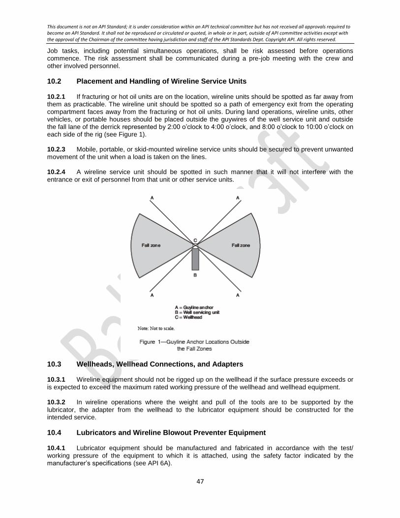
This document is not an API Standard; it is under consideration within an API technical committee but has not received all approvals required to become an API Standard. It shall not be reproduced or circulated or quoted, in whole or in part, outside of API committee activities except with the approval of the Chairman of the committee having jurisdiction and staff of the API Standards Dept. Copyright API. All rights reserved.
47
Job tasks, including potential simultaneous operations, shall be risk assessed before operations commence. The risk assessment shall be communicated during a pre-job meeting with the crew and other involved personnel.
10.2 Placement and Handling of Wireline Service Units 10.2.1 If fracturing or hot oil units are on the location, wireline units should be spotted as far away from them as practicable. The wireline unit should be spotted so a path of emergency exit from the operating compartment faces away from the fracturing or hot oil units. During land operations, wireline units, other vehicles, or portable houses should be placed outside the guywires of the well service unit and outside the fall lane of the derrick represented by 2:00 o’clock to 4:00 o’clock, and 8:00 o’clock to 10:00 o’clock on each side of the rig (see Figure 1). 10.2.3 Mobile, portable, or skid-mounted wireline service units should be secured to prevent unwanted movement of the unit when a load is taken on the lines. 10.2.4 A wireline service unit should be spotted in such manner that it will not interfere with the entrance or exit of personnel from that unit or other service units.
10.3 Wellheads, Wellhead Connections, and Adapters 10.3.1 Wireline equipment should not be rigged up on the wellhead if the surface pressure exceeds or is expected to exceed the maximum rated working pressure of the wellhead and wellhead equipment. 10.3.2 In wireline operations where the weight and pull of the tools are to be supported by the lubricator, the adapter from the wellhead to the lubricator equipment should be constructed for the intended service.
10.4 Lubricators and Wireline Blowout Preventer Equipment 10.4.1 Lubricator equipment should be manufactured and fabricated in accordance with the test/ working pressure of the equipment to which it is attached, using the safety factor indicated by the manufacturer’s specifications (see API 6A).
This document is not an API Standard; it is under consideration within an API technical committee but has not received all approvals required to become an API Standard. It shall not be reproduced or circulated or quoted, in whole or in part, outside of API committee activities except with the approval of the Chairman of the committee having jurisdiction and staff of the API Standards Dept. Copyright API. All rights reserved.
48
10.4.2 Lubricator and wireline blowout preventer equipment should be pressure tested in accordance with manufacturer’s guidelines. 10.4.3 The rated working pressure of the sections of the lubricator, including stuffing box, wireline valve connections, and adapters should not be exceeded. 10.4.4 A lubricator of sufficient pressure rating should be used whenever pressure at the wellhead may be anticipated. The lubricator shall allow removal of the wireline downhole equipment when the master valve or blowout preventer is closed. 10.4.5 Materials to be used in a service that could cause sulfide stress cracking shall meet the requirements of NACE MR0175/ISO15156-1. 10.4.6 Lubricators, swages, and unions shall be visually inspected for defects prior to use. Defects that may affect safe operations (i.e. cuts, corrosion, thread damage) shall be corrected prior to installation. 10.4.7 Check lubricator assembly for pressure, isolate the equipment from the well bore and bleed pressure before working on or breaking a connection. 10.4.8 When a lubricator is installed on a wellhead, a well bore connection (kill line) below the lubricator should be provided for well control operations. 10.4.9 Hammering or otherwise striking a lubricator or connection should not be permitted while they are subjected to pressure. 10.4.10 Threaded connections or unions on lubricators should not be loosened or tightened while they are subjected to pressure. 10.4.11 Due to the nature of wireline operations and where the lubricator shall support the wireline load, relatively high loads can be placed on an unsupported (free standing) lubricator assembly. The stress resulting from side loading is normally highest at the point where the lubricator assembly is connected to the well. The lubricator assembly should be adequately supported and/or properly guyed to reduce the side loading effect of wireline operations.
10.5 Wireline Operations 10.5.1 When handling a wireline that will recoil when released, the loose end should not be left unsecured. 10.5.2 If slack line occurs while tools are in the hole, the wireline should be clamped off at the wellhead prior to working with the slack line. Wire rope or chain should be used to tie off the wireline clamp. The clamp should be held with a device capable of withstanding the loads to which it may be subjected. 10.5.4 Hands, loose clothing, and other objects should be kept clear of sheaves while the line is in motion. 10.5.5 Mast and cranes used in wireline operations should be moved from one location to another, and driven with the mast stored and properly secured. 10.5.6 Use, storage, and transportation of radioactive materials shall comply with applicable standards and regulations. During wireline operations, non-essential personnel should stay clear from radioactive materials.
This document is not an API Standard; it is under consideration within an API technical committee but has not received all approvals required to become an API Standard. It shall not be reproduced or circulated or quoted, in whole or in part, outside of API committee activities except with the approval of the Chairman of the committee having jurisdiction and staff of the API Standards Dept. Copyright API. All rights reserved.
49
10.5.7 Welding operations should not be performed in the immediate wellhead area during wireline operations. 10.5.8 Precaution(s) shall be taken to prevent personnel or vehicles from crossing under or over wirelines or pressurized lines. 10.5.9 Personnel should observe a safe buffer zone on either side of the wireline between the wireline unit and the wellhead when the wireline is in tension or moving. 10.5.10 Wireline wipers should be adequately secured. 10.5.11 Oil savers should be adjusted only by remote control while the wireline is in motion.
10.6 Perforating The wireline supervisor should hold a pre-job meeting with personnel on location to review responsibilities for the operation(s) to be performed. See API 67 for additional information.
10.7 Swabbing 10.7.1 While swabbing operations are being conducted, engines, motors, and other possible sources of ignition not essential to the operation should be shut down. 10.7.2 When swabbing, the swabbing line should be packed off at the surface and have sufficient lubricator length so that fluids are routed through a closed flow system to the maximum extent possible. 10.7.3 Swabbing operations should be conducted during daylight hours or if adequate lighting is provided. 10.7.4 The swabbing unit should be positioned upwind of the swab tanks or pit. 10.7.5 Swab return lines should not be placed under mobile equipment. 10.7.6 When using an open-ended flow line to flow the swabbed well to a pit, the lines should be adequately secured. 10.7.7 Pressure shall be bled from line(s) prior to breaking out or rigging down the line(s). 10.7.8 After hazardous substances have been swabbed, prior to rigging down, lines should be cleared and, if possible, flushed.
10.8 Bailing 10.8.1 Hydrostatic bailers should be secured prior to dumping. Sudden release of high pressure may cause the bailer to whip. 10.8.2 Hydrostatic bailers should not be opened until personnel are clear of the discharge orifice. 10.8.3 Use a hose and flush nozzle to attempt to clear a blocked bailer. Warning – Do not use your fingers when clearing a blocked bailer. 10.8.4 Use of PPE, including slicker and face shield, is recommended to protect against pressurized fluids and solids when clearing a bailer.

This document is not an API Standard; it is under consideration within an API technical committee but has not received all approvals required to become an API Standard. It shall not be reproduced or circulated or quoted, in whole or in part, outside of API committee activities except with the approval of the Chairman of the committee having jurisdiction and staff of the API Standards Dept. Copyright API. All rights reserved.
50
11 Stripping and Snubbing Operations
11.1 General The applicable recommendations and requirements of other sections of this document, in addition to the practices under this section, apply to stripping and snubbing operations.
11.2 Operations 11.2.1 The stripping and snubbing supervisor should hold a pre-job meeting with the stripping and snubbing crew and other involved persons to review responsibilities for the operation(s) to be performed. Personnel involved in the job task(s) should be made aware of the established maximum pressure limit under which safe stripping procedures are permissible. 11.2.2 The snubbing operator and rig operator shall calculate the pipe-heavy or pipe-light point before beginning snubbing operations into or out of the well bore. 11.2.3 An individual emergency escape line shall be available for each person when working atop hydraulic snubbing equipment. 11.2.4 A risk assessment should be performed to determine the appropriate safe location and distance from the wellbore, and appropriate safety measures for the operation and for the location of personnel, engines and other possible sources of ignition. 11.2.5 Prior to commencing snubbing operations, the snubbing work platform shall be guyed if not otherwise supported. 11.2.6 Pumps, power packs, tool boxes, doghouses, and so forth, should be located away from flow lines or bleed-off lines in the event one of these lines should burst. 11.2.7 Pump units should be located where the pump operator can be seen by the snubbing operator. When this is impossible, two-way voice communications with equipment rated for the hazardous location, should be established. 11.2.8 Well pressure should be continuously monitored. 11.2.9 Pipe snubbed into the wellbore should have at least one back pressure valve or blanking plug installed in the pipe string. A back pressure valve or blanking plug installed in a landing nipple, preferably located closest to the lower end of the pipe string, is one means of meeting this practice.
11.2.10 Snubbing operations should not be performed while welding is being done in the immediate vicinity of the wellhead. 11.2.11 The volume(s) of fluids pumped into or bled from the well during snubbing or stripping operations should be measured. 11.2.12 Tool joints or other connections should be lubricated as they go into the hole.
12 Drill Stem Testing
12.1 General The applicable recommendations and requirements of other sections of this document, in addition to the practices under this section, apply to drill stem testing operations.
This document is not an API Standard; it is under consideration within an API technical committee but has not received all approvals required to become an API Standard. It shall not be reproduced or circulated or quoted, in whole or in part, outside of API committee activities except with the approval of the Chairman of the committee having jurisdiction and staff of the API Standards Dept. Copyright API. All rights reserved.
51
12.2 Preliminary to Drill Stem Test 12.2.1 The operator’s representative in charge should hold a pre-job meeting with the crew and other involved personnel to review responsibilities for the operations to be performed. 12.2.2 A risk assessment should be performed to determine the appropriate safe location and distance from the wellbore, and appropriate safety measures for engines during the drill stem testing operations. 12.2.3 Measures should be taken to exclude unauthorized personnel from the area during drill stem testing operations. 12.2.4 Drilling fluid density and viscosity should be checked and maintained within specified limits to minimize blowout possibilities. 12.2.5 A fill-up line should be installed to keep the casing full of drilling fluid, and should be used only for this purpose. Provisions for the kill line should be made separately. 12.2.6 Test line connections to the control head should be secured. 12.2.7 Each test head used above the rig floor should be attached to the elevator links by safety cable or chain. 12.2.8 One or more reversing valve(s) should be incorporated in the test tool assembly. 12.2.9 The swivel/top drive and kelly hose should not be used as part of the test line. 12.2.10 A safety valve of proper size and thread configuration to fit the test string and a properly sized wrench should be readily available on the rig floor for emergency use. A safety valve should not be used in the test string as a pressure control device. 12.2.11 A test line should be laid to a reserve pit or test tank and anchored. If the drill stem test recovery is to be flared as produced, more than one pilot light may be needed to assure that ignition is achieved under both high velocity and low velocity discharge conditions. 12.2.12 If hydrogen sulfide is suspected or known to be present in the area, the applicable recommendations of API 49 and API 68 should be referenced. 12.2.13 For offshore operations and applicable onshore operations, the complete gas detection system and safety equipment including emergency shutdown systems, fire-fighting systems, alarms and communication systems, shall be verified as fully operational prior to the commencement of testing operations. 12.2.14 The service partner provider should develop a diagram of the lines in the well test system, including the flow paths from the drill stem through the well test equipment, bleed off points, and emergency shutdown system. 12.2.15 Connections on pressurized lines shall be secured with adequate means to prevent them from swinging or kicking in case of sudden release of pressure or rupture of the line and shall be suitable for the pressure intended. 12.2.16 Adequate volumes of kill weight fluid shall be on location prior to flowing the well. 12.2.17 Surface well testing and completion equipment shall be pressure tested with water to a set point above the maximum anticipated surface pressure prior to being exposed to the well bore pressure. A full function test of the valves and automatic systems shall be conducted and the well test / DST emergency shutdown system operation verified as applicable.

This document is not an API Standard; it is under consideration within an API technical committee but has not received all approvals required to become an API Standard. It shall not be reproduced or circulated or quoted, in whole or in part, outside of API committee activities except with the approval of the Chairman of the committee having jurisdiction and staff of the API Standards Dept. Copyright API. All rights reserved.
52
12.2.18 Air lines to burners shall be fitted with non-return valves. The air supply shall be independent of the rig’s air supply system.
12.3 Performing the Drill Stem Test 12.3.1 Fluid volume in the casing should be monitored while going in and coming out of the hole to assure that the well remains under hydrostatic control. 12.3.2 The mud bucket should be hooked up and ready for use before the drill stem test tool is pulled out of the hole. 12.3.3 The rig floor should not be left unattended during the drill stem test. 12.3.4 Test tools should be initially opened only in daylight hours or where adequate lighting is provided. 12.3.5 For offshore operations, support vessels and helicopters in the vicinity shall be informed of the time of commencement of testing. 12.3.6 The maximum anticipated temperature during the well test shall not exceed the continuous temperature rating of the BOP elastomers. 12.3.7 The well test tree control station shall be continuously manned. 12.3.8 For offshore operations, prior to installation and subsequent use of the burner/flare boom system, a risk assessment shall be performed to assess hazards. A permit-to-work system can be used to manage its operation thereafter.
13 Acidizing, Fracturing, and Hot Oil Operations
13.1 General 13.1.1 The applicable recommendations and requirements of other sections of this document, in addition to the practices under this section, apply to acidizing, fracturing, and hot oil operations. 13.1.2 The operator’s representative in charge should hold a pre-job meeting with the crew and other involved personnel to review the operations to be performed. 13.1.3 A risk assessment should be performed to determine the appropriate safe location and distance from the wellbore, and appropriate safety measures for trucks and tanks on location. NOTE The risk assessment may include reassessing the location when there are changes in environmental conditions or potential exposure to airborne contaminants (e.g. silica, diesel particulates, caustic and hydrocarbon volatile organic compounds).
13.1.4 Lines connected from the pumping equipment to the Christmas tree or wellhead should have a check valve installed as close to the well as practicable. In addition, when a multi-pump manifold is used, a check valve should be placed in each discharge line as close to the manifold as possible. 13.1.5 All flowlines and relief lines should be restrained to prevent potential “whipping” of these lines or a designated buffer zone established. 13.1.6 When pumping flammable fluids, the blending equipment used shall be grounded. 13.1.7 Equipment unloading sand into the hopper should be bonded or grounded.

This document is not an API Standard; it is under consideration within an API technical committee but has not received all approvals required to become an API Standard. It shall not be reproduced or circulated or quoted, in whole or in part, outside of API committee activities except with the approval of the Chairman of the committee having jurisdiction and staff of the API Standards Dept. Copyright API. All rights reserved.
53
13.1.8 Lines containing flammable fluids shall not be laid under vehicles. 13.1.9 A pre-treatment pressure test on the pump and discharge lines should be made at a pressure no less than the maximum expected treating pressure specified by the operator, but not to exceed the rated working pressure of the equipment with the lowest rated working pressure. 13.1.10 Personnel not directly involved in the operations should remain beyond a designated minimum distance during pressure testing and pumping operations. 13.1.11 The pumping supervisor or the person designated should check to see that valves in discharge lines are open prior to pumping. 13.1.12 Unguarded openings in the top of covered frac tanks or other covered service tanks should be too small to allow personnel entry. An opening large enough to permit personnel entry should be covered by a hatch or bars mechanically secured to prevent personnel entry while the tank is on location. If securing the opening is not feasible, appropriate warning signs shall be prominently posted in close proximity to the tank opening. 13.1.13 Engineering controls and PPE shall be used to protect personnel from silica exposure.
13.2 Pumping Operations 13.2.1 The equipment operator should remain at the controlling station while the equipment is in operation, unless relieved as directed by the pumping supervisor. Equipment operators should remain alert for communications from the pumping supervisor. 13.2.2 While pumping flammable fluids, electrical equipment and internal combustion equipment not used in performance of the job should be shut down or shut off and fires should be extinguished. At locations where this recommendation may be impractical, appropriate safety measures should be implemented. 13.2.3 Flammable fluids should not be bled back into open measuring tanks on equipment designed for pumping. 13.2.4 Control measures should be in place to prevent spills or accidental releases on location. 13.2.5 For additional information to consider in the planning and operating of hydraulic fracturing, see API 100-1 and API 100-2.
14 Cementing Operations
14.1 General 14.1.1 The applicable recommendations and requirements of other sections of this document, in addition to the practices under this section, apply to cementing operations. A risk assessment should be performed to determine the appropriate safe location and distance from the wellbore, and appropriate safety measures for trucks and tanks on location. 14.1.2 The cementing supervisor should hold a pre-job meeting with the cementing crew and other involved persons to review responsibilities for the operation(s) to be performed. 14.1.3 Personnel not directly involved in the operations should remain beyond a designated minimum distance during pressure testing and pumping operations.

This document is not an API Standard; it is under consideration within an API technical committee but has not received all approvals required to become an API Standard. It shall not be reproduced or circulated or quoted, in whole or in part, outside of API committee activities except with the approval of the Chairman of the committee having jurisdiction and staff of the API Standards Dept. Copyright API. All rights reserved.
54
14.1.4 Prior to commencing operations, the pump and discharge lines should be tested to a pressure no less than the maximum cementing pressure specified by the operator, but not exceeding the rated working pressure of the equipment. 14.1.5 The cementing supervisor or the person designated should check to see that the valves in the pump discharge lines are open prior to pumping. 14.1.6 The lead-off connection to the cementing head should be secured prior to pumping operations. 14.1.7 The valves and sections of cementing lines left after completion of cementing operations should be secured to prevent whipping when pressure is bled off. 14.1.8 All flowlines and relief lines should be restrained to prevent potential “whipping” of these lines or a designated buffer zone established. 14.1.9 Consideration should be given to personnel safety when releasing cement wiper plugs under pressure. 14.1.10 When cementing at shallow depths, the casing should be secured to prevent pumping the casing from the hole. 14.1.11 Engineering controls and PPE shall be used to protect personnel from silica exposure.
14.2 Pumping Operations Pump operators should remain at the controls while the pump is in operation, unless relieved as directed by the cementing supervisor.
15 Gas, Air, or Mist Drilling Operations
15.1 General 15.1.1 The applicable recommendations and requirements of other sections of this document, in addition to the practices under this section, apply to gas, air, or mist drilling operations. 15.1.2 A risk assessment should be performed to determine the appropriate safe location and distance from the wellbore, and appropriate safety measures for compressors.
15.2 Training 15.2.1 Personnel directly involved in gas, air, or mist drilling operations should be trained in the use of emergency shutoff, blowout preventer, and fire-fighting equipment. 15.2.2 Personnel should be familiarized with the air or gas supply and circulating system.
15.3 Equipment 15.3.1 If practicable, compressors should be placed so as to be visible from the driller’s position. 15.3.2 Compressors should have such safety features as pressure relief valves, discharge temperature and pressure gauges, engine governors, and engine shut off valves. 15.3.3 Kill switches should be provided for the drilling engines and should be mounted in close proximity to the driller’s console for immediate emergency use.

This document is not an API Standard; it is under consideration within an API technical committee but has not received all approvals required to become an API Standard. It shall not be reproduced or circulated or quoted, in whole or in part, outside of API committee activities except with the approval of the Chairman of the committee having jurisdiction and staff of the API Standards Dept. Copyright API. All rights reserved.
55
15.3.4 All surface lines should be rated for the maximum anticipated pressure. 15.3.4 The discharge line from each compressor should be equipped with a check valve and a block valve. 15.3.5 To minimize the possibility of explosion that could result from accumulation of air cylinder lubricants in the air supply line, it is important that proper lubricants be used. Additionally, for this reason, scrubbers should be used after each stage of compression to remove entrained oil. 15.3.6 Compressors should be equipped with after-coolers designed to maintain temperatures within the limitations of the downstream piping system. 15.3.7 A rotating head may be used on the blowout preventer assembly with appropriate working pressure. 15.3.8 The blooey and bleed-off lines should be a minimum of 150 ft (45.8 m) in length or equivalent safety measures shall be taken. The blooey and bleed-off line should be located downwind of the rig for the prevailing wind direction at the location. Equivalent safety measures should be taken for other wind conditions. These lines should be laid from the wellbore as straight and free of sags as practicable and be securely anchored. 15.3.9 The blooey line should be as large as or larger than the rotating head outlet into the blooey line. 15.3.10 The blooey and bleed-off lines should be securely anchored to prevent movement when pressure surges occur. This is particularly applicable in mist drilling. 15.3.11 A full-opening, quick-closing valve (stopcock) should be installed at the top of the kelly to contain formation pressures in the drill string. 15.3.12 There should be two valves installed in the standpipe, one accessible on the rig floor and one at ground level below the rig floor, to control the air or gas supply to the borehole. 15.3.13 In gas drilling operations, a shutoff valve should be installed on the main feeder line a minimum of 150 ft (45.8 m) from the wellhead. In air drilling operations, the shut-off valve should be installed in the main feeder line closest to the compressors. 15.3.14 Geological sample catchers attached to the blooey line should be of design to protect personnel from deflected solids in the air or gas flow (see Figure 2).
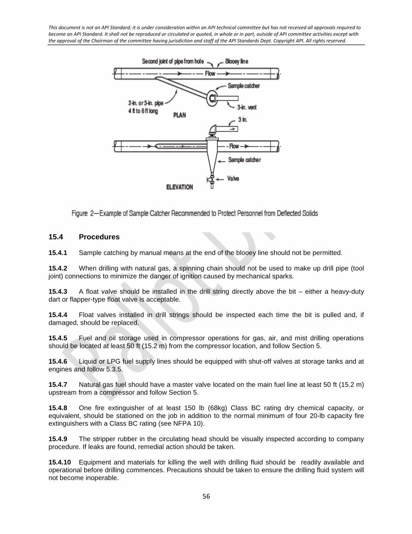
This document is not an API Standard; it is under consideration within an API technical committee but has not received all approvals required to become an API Standard. It shall not be reproduced or circulated or quoted, in whole or in part, outside of API committee activities except with the approval of the Chairman of the committee having jurisdiction and staff of the API Standards Dept. Copyright API. All rights reserved.
56
15.4 Procedures 15.4.1 Sample catching by manual means at the end of the blooey line should not be permitted. 15.4.2 When drilling with natural gas, a spinning chain should not be used to make up drill pipe (tool joint) connections to minimize the danger of ignition caused by mechanical sparks. 15.4.3 A float valve should be installed in the drill string directly above the bit – either a heavy-duty dart or flapper-type float valve is acceptable. 15.4.4 Float valves installed in drill strings should be inspected each time the bit is pulled and, if damaged, should be replaced. 15.4.5 Fuel and oil storage used in compressor operations for gas, air, and mist drilling operations should be located at least 50 ft (15.2 m) from the compressor location, and follow Section 5. 15.4.6 Liquid or LPG fuel supply lines should be equipped with shut-off valves at storage tanks and at engines and follow 5.3.5. 15.4.7 Natural gas fuel should have a master valve located on the main fuel line at least 50 ft (15.2 m) upstream from a compressor and follow Section 5. 15.4.8 One fire extinguisher of at least 150 lb (68kg) Class BC rating dry chemical capacity, or equivalent, should be stationed on the job in addition to the normal minimum of four 20-lb capacity fire extinguishers with a Class BC rating (see NFPA 10). 15.4.9 The stripper rubber in the circulating head should be visually inspected according to company procedure. If leaks are found, remedial action should be taken. 15.4.10 Equipment and materials for killing the well with drilling fluid should be readily available and operational before drilling commences. Precautions should be taken to ensure the drilling fluid system will not become inoperable.

This document is not an API Standard; it is under consideration within an API technical committee but has not received all approvals required to become an API Standard. It shall not be reproduced or circulated or quoted, in whole or in part, outside of API committee activities except with the approval of the Chairman of the committee having jurisdiction and staff of the API Standards Dept. Copyright API. All rights reserved.
57
15.4.11 A dedicated hydrocarbon ignition source shall be kept operational at the end of the flow line, except when the stripper rubber is being removed 15.4.12 For air drilling operations, an air compressor should be kept operating during trips with a discharge of air through the blooey line. 15.4.13 When making a connection, the standpipe valve should be closed and the bleed-off line should be opened prior to breaking out the tool joint. 15.4.14 Upon returning to the bottom of the hole at the conclusion of a trip in gas drilling operations, gas should be circulated to assure that air is out of the circulating system prior to lighting the flare.
15.5 Minimizing Sources of Ignition 15.5.1 To prevent or minimize objectionable quantities of dust permeating areas surrounding the blooey line discharge, an appropriate amount of water should be introduced into the blooey line to wet cuttings. 15.5.2 The rig substructure should have appropriate measures to prevent or mitigate the accumulation of hydrocarbon gases.
16 Flowback Operations
16.1 The applicable recommendations and requirements of other sections of this document, in addition to the practices under this section, apply to flowback operations. 16.2 A risk assessment should be performed to determine the appropriate safe location and distance from the wellbore, and appropriate safety measures for trucks, tanks, and other flowback equipment on location. The assessment should include the piping and instrumentation diagram. 16.3 A meeting with involved personnel should be conducted to review the operations to be
performed before starting work, anytime equipment is reconfigured and/or when there are significant
operational changes.
16.4 Personnel involved in the operations shall perform routine equipment checks throughout the shift. These checks will involve audio, visual and olfactory observations. 16.5 Engineering controls and PPE shall be used to protect personnel from hydrocarbon and/or H2S vapor exposure. 16.6 All enclosed gas busters/separators should relieve to applicable venting and/or flaring options depending on local or other regulatory requirements. 16.7 All flare lines, when in use, should have flame arrestors placed as close to the flare as possible. 16.8 All wells equipped with remote shut-off devices (hydraulic or pneumatic operating) should have the emergency shutdown system located along the path of egress and be tested prior to commencing flowback operations. 16.9 All flowlines and relief lines should be restrained to prevent potential “whipping” of these lines or a designated buffer zone established. 16.10 All equipment should be pressure tested before use.

This document is not an API Standard; it is under consideration within an API technical committee but has not received all approvals required to become an API Standard. It shall not be reproduced or circulated or quoted, in whole or in part, outside of API committee activities except with the approval of the Chairman of the committee having jurisdiction and staff of the API Standards Dept. Copyright API. All rights reserved.
58
16.11 All flowback iron shall be certified/recertified annually using nondestructive testing. Banding is required to show the test date for all iron to ensure compliance. Any iron with missing or illegible bands will be taken out of service immediately and sent in for certification. The bands shall be visible after rig-up. NOTE See manufacturer’s information or recommendations on banding.
16.12 All equipment shall be bonded and grounded when in use. 16.13 All tanks should have internal grounding using a static drain line for static dissipation for the incoming fluids. 16.14 Non-metallic containers should not be used to drain or sample hydrocarbon fluids.
This document is not an API Standard; it is under consideration within an API technical committee but has not received all approvals required to become an API Standard. It shall not be reproduced or circulated or quoted, in whole or in part, outside of API committee activities except with the approval of the Chairman of the committee having jurisdiction and staff of the API Standards Dept. Copyright API. All rights reserved.
59
Bibliography
[1] API Bulletin 97, Well Construction Interface Document Guidelines
[2] API Bulletin 100-3, Community Engagement Guidelines
[3] API Recommended Practice 2D, Operation and Maintenance of Offshore Cranes
[4] API Recommended Practice 4G, Operation, Inspection, Maintenance, and Repair of Drilling and Well Servicing Structures
[5] API Recommended Practice 8B, Procedures for Inspection, Maintenance, Repair, and Remanufacture of Hoisting Equipment
[6] API Recommended Practice 9B, Application, Care, and Use of Wire Rope for Oilfield Service
[7] API Recommended Practice 14F, Design, Installation, and Maintenance of Electrical Systems for Fixed and Floating Offshore Petroleum Facilities for Unclassified and Class 1, Division 1 and Division 2 Locations
[8] API Recommended Practice 14FZ, Design, Installation, and Maintenance of Electrical Systems for Fixed and Floating Offshore Petroleum Facilities for Unclassified and Class 1, Zone 0, Zone 1, and Zone 2 Locations
[9] API Recommended Practice 16ST, Coiled Tubing Well Control Equipment Systems
[10] API Recommended Practice 49, Drilling and Well Servicing Operations Involving Hydrogen Sulfide
[11] API Recommended Practice 55, Oil and Gas Producing and Gas Processing Plant Operations Involving Hydrogen Sulfide
[12] API Recommended Practice 59, Well Control Operations
[13] API Recommended Practice 67, Oilfield Explosives Safety
[14] API Recommended Practice 68, Oil and Gas Well Servicing and Workover Operations Involving Hydrogen Sulfide
[15] API Recommended Practice 92U, Underbalanced Drilling Operations
[16] API Recommended Practice 65, Cementing Shallow Water Flow Zones in Deepwater Wells
[17] API Recommended Practice 96, Deepwater Well Design and Construction
[18] API Recommended Practice 99, Flash Fire Risk Assessment for the Upstream Oil and Gas Industry
[19] API Recommended Practice 100-1, Hydraulic FracturingWell Integrity and Fracture Containment
[20] API Recommended Practice 100-2, Managing Environmental Aspects Associated with Exploration and Production Operations Including Hydraulic Fracturing
[21] API Recommended Practice 510, Pressure Vessel Inspection Code: In-service Inspection, Rating, Repair and Alteration
[22] API Recommended Practice 2003, Protection Against Ignitions Arising Out of Static, Lightning, and Stray Currents
[23] API Recommended Practice 2009, Safe Welding, Cutting, and Hot Work Practices in the Petroleum and Petrochemical Industries
[24] API Recommended Practice 2016, Guidelines and Procedures for Entering and Cleaning Petroleum Storage Tanks

This document is not an API Standard; it is under consideration within an API technical committee but has not received all approvals required to become an API Standard. It shall not be reproduced or circulated or quoted, in whole or in part, outside of API committee activities except with the approval of the Chairman of the committee having jurisdiction and staff of the API Standards Dept. Copyright API. All rights reserved.
60
[25] API Recommended Practice 2201, Safe Hot Tapping Practices in the Petroleum and Petrochemical Industries
[26] API Specification 4F, Drilling and Well Servicing Structures
[27] API Specification 6A, Wellhead and Christmas Tree Equipment
[28] API Specification 8A, Drilling and Production Hoisting Equipment
[29] API Specification 8C, Drilling and Production Hoisting Equipment (PSL 1 and PSL 2)
[30] API Standard 53, Blowout Prevention Equipment Systems for Drilling Operations
[31] API Standard 65-2, Isolating Potential Flow Zones During Well Construction
[32] API Standard 2015, Safe Entry and Cleaning of Petroleum Storage Tanks
[33] ACGIH, Industrial Ventilation, A Manual of Recommended Practice for Design
[34] ACGIH, Documentation of the Threshold Limit Values for Chemical Substances
[35] ANSI/ASA S1.4/IEC 61672-3, Electroacoustics–Sound Level Meters–Part 3: Period Tests
[36] ANSI/ASA S1.13, Measurement of Sound Pressure Levels in Air
[37] ANSI/ASA S12.6, Methods for Measuring the Real-Ear Attenuation of Hearing Protectors
[38] ANSI/ASSE A1264.1, Safety Requirements for Workplace Walking/Working Surfaces and Their Access; Workplace, Floor, Wall and Roof Openings; Stairs and Guardrail/Handrail Systems
[39] ANSI/ASSE B11.19, Performance Requirements for Safeguarding
[40] ANSI/ASSE Z88.2, Practices for Respiratory Protection
[41] ANSI/ASSE Z117, Safety Requirements for Entering Confined Space
[42] ANSI/IES RP-7, Recommended Practice for Lighting Industrial Facilities
[43] ANSI/ISEA Z358.1, Emergency Eyewash and Shower Equipment
[44] ASME B15.1, Safety Standard for Mechanical Power Transmission Apparatus
[45] ASME Boiler and Pressure Vessel Code (BPVC)Section VIII, Pressure Vessels
[46] ASME Boiler and Pressure Vessel Code (BPVC)Section IX, Welding and Brazing Qualifications
[47] ASNT Recommended Practice No. ASNT-TC-1A, Personnel Qualification and Certification in Nondestructive Testing
[48] ASTM F2412, Standard Test Methods for Foot Protection
[49] CGA C7, Guide to Classification and Labeling of Compressed Gases
[50] IME Safety Library Publications 20, Safety Guide for the Prevention of Radio Frequency Radiation Hazards in the Use of Commercial Electrical Detonators (Blasting Caps)
[51] Institute of Petroleum (IP), Recommended Practices for Radio Silence When Conducting Wireline Services Involving the Use of Explosives, December 19
th 1984
[52] NFPA 10, Standard for Portable Fire Extinguishers
[53] NFPA 30, Flammable and Combustible Liquids Code
[54] NFPA 77, Recommended Practice on Static Electricity