oc1 o 4 zorn - nrc.gov · Charles R. Pierce Regulatory Affairs Director oc1 o 4 zorn Docket Nos.:...
101
Charles R. Pierce Regulatory Affairs Director oc1 o4 zorn Docket Nos.: 50-348 50-364 Southern Nuclear Operating Company, Inc. 40 Inverness Center Parkway Post Office Box 1295 Birmingham, AL 35242 Tel 205.992.7872 Fax 205.992.7601 Southern Nuclear NL-16-1128 U. S. Nuclear Regulatory Commission ATTN: Document Control Desk Washington, D.C. 20555-0001 Southern Nuclear Operating Company Joseph M. Farley Nuclear Plant Units 1 and 2; License Amendment Request to Revise Technical Specification Section 5.5.17 for Permanent Extension of Type A and Type C Leak Rate Test Frequencies Ladies and Gentlemen: Pursuant to 10 CFR 50.90, Southern Nuclear Operating Company (SNC) requests an amendment to the Joseph M. Farley Nuclear Plant (FNP) Unit 1, Renewed Facility Operating License (NPF-2), and Unit 2, Renewed Facility Operating License (NPF-8), by incorporating the attached proposed change into the Unit 1 and Unit 2 Technical Specifications (TS). Specifically, the proposed change is a request to revise TS 5.5.17 "Containment Leakage Rate Testing Program" to allow the following: • Increase in the existing Type A integrated leakage rate test (ILRT) program test interval from 1 O years to 15 years in accordance with Nuclear Energy Institute (NEI) Topical Report NEI 94-01, Revision 3-A and the conditions and limitations specified in NEI 94- 01, Revision 2-A. • Adopt an extension of the containment isolation valve (CIV) leakage testing (Type C) frequency from the 60 months currently permitted by 1 O CFR 50, Appendix J, Option B, to a 75-month frequency for Type C leakage rate testing of selected components, in accordance with NEI 94-01, Revision 3-A. • Adopt the use of American National Standards Institute/American Nuclear Society (ANSI/ANS) 56.8-2002, Containment System Leakage Testing Requirements. • Adopt a more conservative grace interval of 9 months, for Type A, Type B and Type C leakage tests in accordance with NEI 94-01, Revision 3-A. The proposed change to the TS contained herein would revise FNP TS 5.5.17, by replacing the references to Regulatory Guide (RG) 1.163, Performance-Based Containment Leak-Test Program and 1 O CFR 50, Appendix J, Option B with a reference to NEI topical report NEI 94-01, Revision 3-A (Reference 2), dated July 2012, and the conditions and limitations specified in NEI 94-01, Revision 2-A dated October 2008, as the documents used by FNP to implement the O () [ fr
Transcript of oc1 o 4 zorn - nrc.gov · Charles R. Pierce Regulatory Affairs Director oc1 o 4 zorn Docket Nos.:...

Charles R. Pierce Regulatory Affairs Director
oc1 o 4 zorn Docket Nos.: 50-348
50-364
Southern Nuclear Operating Company, Inc. 40 Inverness Center Parkway Post Office Box 1295 Birmingham, AL 35242
Tel 205.992.7872 Fax 205.992.7601
.~ Southern Nuclear
NL-16-1128
U. S. Nuclear Regulatory Commission ATTN: Document Control Desk Washington, D.C. 20555-0001
Southern Nuclear Operating Company Joseph M. Farley Nuclear Plant Units 1 and 2;
License Amendment Request to Revise Technical Specification Section 5.5.17 for Permanent
Extension of Type A and Type C Leak Rate Test Frequencies
Ladies and Gentlemen:
Pursuant to 10 CFR 50.90, Southern Nuclear Operating Company (SNC) requests an amendment to the Joseph M. Farley Nuclear Plant (FNP) Unit 1, Renewed Facility Operating License (NPF-2), and Unit 2, Renewed Facility Operating License (NPF-8), by incorporating the attached proposed change into the Unit 1 and Unit 2 Technical Specifications (TS). Specifically, the proposed change is a request to revise TS 5.5.17 "Containment Leakage Rate Testing Program" to allow the following:
• Increase in the existing Type A integrated leakage rate test (ILRT) program test interval from 1 O years to 15 years in accordance with Nuclear Energy Institute (NEI) Topical Report NEI 94-01, Revision 3-A and the conditions and limitations specified in NEI 94-01, Revision 2-A.
• Adopt an extension of the containment isolation valve (CIV) leakage testing (Type C) frequency from the 60 months currently permitted by 1 O CFR 50, Appendix J, Option B, to a 75-month frequency for Type C leakage rate testing of selected components, in accordance with NEI 94-01, Revision 3-A.
• Adopt the use of American National Standards Institute/American Nuclear Society (ANSI/ANS) 56.8-2002, Containment System Leakage Testing Requirements.
• Adopt a more conservative grace interval of 9 months, for Type A, Type B and Type C leakage tests in accordance with NEI 94-01, Revision 3-A.
The proposed change to the TS contained herein would revise FNP TS 5.5.17, by replacing the references to Regulatory Guide (RG) 1.163, Performance-Based Containment Leak-Test Program and 1 O CFR 50, Appendix J, Option B with a reference to NEI topical report NEI 94-01, Revision 3-A (Reference 2), dated July 2012, and the conditions and limitations specified in NEI 94-01, Revision 2-A dated October 2008, as the documents used by FNP to implement the O () [
fr ~t~

U.S. Nuclear Regulatory Commission NL-16-1128 . Page2
performance-based leakage testing program in accordance with Option B of 1 O CFR 50, Appendix J. This license amendment request (LAR) also proposes the following administrative changes to TS 5.5.12:
• Deleting the information regarding the performance of the next FNP Unit 1 and Unit 2 Type A test to be performed during refueling outage R22 for Unit 1 and refueling outage R20 for Unit 2, as both Type A tests have already occurred.
SNC requests approval within 12 months. The proposed changes will be implemented within six months of issuance of the amendment.
The Enclosure provides the evaluation of the proposed change and includes attachments with the risk assessment supporting the proposed amendment along with mark-ups of the TS pages and re-typed TS pages.
This letter contains no NRG commitments. If you have any questions, please contact Ken McElroy at 205.992.7369.
Mr. C. R. Pierce states he is the Regulatory Affairs Director for Southern Nuclear Operating Company, is authorized to execute this oath on behalf of Southern Nuclear Operating Company and, to the best of his knowledge and belief, the facts set forth in this letter are true.
Respectfully s~ted, c 1<-~~ .-/' .,,. C. R. Pierce ·.·
.·_:
Regulatory Affairs Director . _;-
crp/efb/lac ~ ' -, :
efore me this 4 t::!:- day of GJcJo k '2016.
Notary Public
My commission expires: /7J -"% -d..D f /}
_ ...... -

U.S. Nuclear Regulatory Commission NL-16-1128 Page3
Enclosure: 1. Evaluation of Proposed Change
cc: Southern Nuclear Operating Company Mr. S. E. Kuczynski, Chairman, President & CEO Mr. D. G. Bost, Executive Vice President & Chief Nuclear Officer Ms. C. A. Gayheart, Vice President...,.. Farley Mr. M. D. Meier, Vice President - Regulatory Affairs Mr. R J. Adams, Vice President- Engineering Mr. Mitch Etten-Bohm, Senior Engineer
·Ms. B. L. Taylor, Regulatory Affairs Manager - Farley RType: Farley=CFA04.054
U. S. Nuclear Regulatory Commission Ms. C. Haney, Regional Administrator Mr. S. A. Williams, NRR Senior Project Manager - Farley Mr. P. K. Niebaum, Senior Resident Inspector- Farley
Alabama Department of Public Health Dr. T. M. Miller, MD, State Health Officer
Southern Nuclear Operating Company Joseph M. Farley Nuclear Plant Units 1 and 2; License Amendment Request for Changes to
License Amendment Request to Revise Technical Specification Section 5.5.12 for Permanent
Extension of Type A and Type C Leak Rate Test Frequencies
Enclosure
Evaluation of Proposed Change

Southern Nuclear Operating Company
Joseph M. Farley Nuclear Plant Units 1 and 2;
License Amendment Request for Changes to
License Amendment Request to Revise
Technical Specification Section 5.5.12 for Permanent
Extension of Type A and Type C Leak Rate Test Frequencies
1 of 173

EVALUATION OF PROPOSED CHANGE
SUBJECT: Revise Technical Specification 5.5.17 for Permanent Extension of Type A and Type C Leak Rate Test Frequencies
1.0 SUMMARY DESCRIPTION
2.0 DETAILED DESCRIPTION
3.0 TECHNICAL EVALUATION
4.0 REGULATORY EVALUATION
4.1 Applicable Regulatory Requirements/Criteria 4.2 Precedent 4.3 No Significant Hazards Consideration 4.4 Conclusion
5.0 ENVIRONMENTAL CONSIDERATION
6.0 REFERENCES
Attachments: 1. Permanent ILRT Interval Extension Risk Impact Assessment 2. Proposed Technical Specification 5.5.17 (Markup) 3. Re-Typed (Clean-copy) TS page (TS 5.5.17)
Joseph M. Farley Nuclear Plant, Units 1 and 2 2of173

1.0 SUMMARY DESCRIPTION
In accordance with 10 CFR 50.90, "Application for amendment of license, construction permit, or early site permit," Southern Nuclear Company (SNC) requests an amendment to Facility Operating License NPF-2 and NPF-8 for Joseph M. Farley Nuclear Plant (FNP), Units 1 and 2, respectively. The proposed change revises Technical Specification (TS) 5.5.17, "Primary Containment Leakage Rate Testing Program," to allow the following:
• Increase the existing Type A integrated leakage rate test (ILRT) program test interval from 1 O years to 15 years in accordance with Nuclear Energy Institute (NEI) Topical Report (TR) NEI 94-01, "Industry Guideline for Implementing Performance-Based Option of 1 O CFR 50, Appendix J," Revision 3-A (Reference 1) and the conditions and limitations specified in NEI 94-01, Revision 2-A (Reference 2).
• Adopt an extension of the containment isolation valve (CIV) leakage rate testing (Type C) frequency from the 60 months currently permitted by 10 CFR 50, Appendix J, "Primary Reactor Containment Leakage Testing for Water-Cooled Power Reactors," Option B, to a 75-month frequency for Type C leakage rate testing of selected components, in accordance with NEI 94-01, Revision 3-A.
• Adopt the use of American National Standards Institute/American Nuclear Society (ANSI/ANS) 56.8-2002, "Containment System Leakage Testing Requirements" (Reference 4).
• Adopt a more conservative allowable test interval extension of nine months, for Type A, Type Band Type C leakage rate tests in accordance with NEI 94-01, Revision 3-A.
Specifically, the proposed change contained herein revises FNP TS 5.5.17, by replacing the references to Regulatory Guide (RG) 1.1.63, "Performance-Based Containment Leak-Test Program," (Reference 1) and 10 CFR Part 50, Appendix J, Option B with a reference to NEI 94-01, Revision 3-A (Reference 2), and the conditions and limitations specified in NEI 94-01, Revision 2-A (Reference 3), as the documents used by FNP to implement the performance-based leakage testing program in accordance with Option B of 10 CFR 50, Appendix J.
This LAR also proposes administrative changes to the exceptions in TS 5.5.17. The exception regarding the performance of the next FNP Type A test, at each unit, to be performed during refueling outage R22 (Spring 2009) for Unit 1 and during refueling outage R20 (Spring 2010) for Unit 2 will be deleted as these Type A tests have already occurred.
2.0 DETAILED DESCRIPTION
FNP TS 5.5.17, "Primary Containment Leakage Rate Testing Program," currently states, in part:
"A program shall be established to implement the leakage rate testing of containment as required by 10 CFR 50.54(0) and 10 CFR 50, Appendix J, Option B, as modified by approved exemptions. This program shall be in accordance with the guidelines contained in Regulatory Guide 1.163, "Performance Based Containment Leak Test Program," dated September 1995, as modified by the following exception to NEI 94-01, Rev. 0, "Industry Guidelines for Implementing Performance Based Option of 1 O CFR 50, Appendix J":
3of173

Section 9.2.3: The next Type A test, after the March 1994 test for Unit 1 and the March 1995 test for Unit 2, shall be performed during refueling outage R22 (Spring 2009) for Unit 1 and during refueling outage R20 (Spring 2010) for Unit 2. This is a one-time exception."
The proposed changes to FNP TS 5.5.17 will replace the reference to RG 1.163 with a reference to NEI TR 94-01, Revisions 2-A and 3-A. This LAR also proposes an administrative change to the exception in TS 5.5.17. The exception regarding the performance of the next FNP Type A test, at each unit, to be performed during refueling outage R22 (Spring 2009) for Unit 1 and during refueling outage R20 (Spring 2010) for Unit 2 will be deleted as these Type A tests have already occurred.
The proposed change will revise TS 5.5.17 to state, in part:
"A program shall be established to implement the leakage rate testing of containment as required by 10 CFR 50.54(0) and 10 CFR 50, Appendix J, Option B, as modified by approved exemptions. This program shall be in accordance with the guidelines contained in NEI 94-01, "Industry Guideline for Implementing Performance-Based Option of 10 CFR Part 50, Appendix J," Revision 3-A, dated July 2012, and the conditions and limitations specified in NEI 94-01, Revision 2-A, dated October 2008.
A markup of the proposed change to TS 5.5.17 is provided in Attachment 2. Attachment 3 provides the "clean" retyped TS 5.5.17.
Attachment 1 contains the plant specific risk assessment conducted to support this proposed change. This risk assessment followed the guidelines of NRC RG 1.174, Revision 2 (Reference 6) and NRC RG 1.200, Revision 2 (Reference 7). The risk assessment concluded that the increase in risk as a result of this proposed change is small and is well within established guidelines.
3.0 TECHNICAL EVALUATION
3.1 Description of Primary Containment System
The containment is a pre-stressed, reinforced concrete cylindrical structure with a shallow domed roof and a reinforced concrete foundation slab with provision for a reactor cavity at the center. The cylindrical portion of the containment is pre-stressed by a post-tensioning system composed of horizontal and vertical tendons. The horizontal tendons are placed in three 240-degree segments using three buttresses spaced 120 degrees apart as supports for the anchorages. The dome has a three-way tendon pattern in which groups of tendons intersect at 120 degrees. The concrete foundation is a conventionally reinforced mat. A continuous access gallery is provided beneath the base slab for installation and inspection of the vertical tendons.
A 1 /4-inch-thick welded steel liner is attached to the inside face of the concrete. The floor liner is installed on top of the foundation slab and is then covered with concrete. The steel liner plate and penetrations are designed to serve as the leakage barrier for the containment. The design of the liner plate considers the composite action of the liner and the concrete structure and includes the transient effects on the liner due to temperature changes during construction, normal operation, and the loss-of-coolant accident. The changes in strains to be experienced by the liner due to these effects, and those at the pressure testing of the containment, are considered. The
4of173

stability of the liner is achieved by anchoring it to the concrete structure. At all penetrations, the liner is thickened to reduce stress concentration. The thickened plate is also anchored to the concrete.
3.1.1 Containment Isolation System
The containment isolation system is in conformance with the NRC acceptance criteria contained in General Design Criteria (GDC) 54, 55, 56, and 57 and RG 1.11 (Reference 8). The general design basis governing isolation valve requirements is as follows:
Leakage through all fluid penetrations not serving accident consequence limiting systems is minimized by a double barrier so that no single credible failure or malfunction of an active component results in loss of isolation or intolerable leakage. The installed double barriers take the form of closed piping systems, both inside and outside the containment, and various types of isolation valves.
Containment isolation in nonessential process lines occurs coincident with the safety injection (SI) actuation signal. Valves, which isolate penetrations that are directly open to the containment, such as the purge valves and sump drain valves, are included in this group. Isolation of valves in essential process lines, such as reactor coolant pump (RCP) cooling, occurs coincident with containment spray (CS) actuation signal.
In accordance with GDC 54, fluid lines penetrating the containment are provided with isolation capability as follows:
Type I
Type II
Type Ill
Each line connecting directly to the reactor coolant systems (RCSs) has two CIVs. One valve is located inside the containment and is either an automatic valve, locked closed, or a check valve depending on the direction of normal flow. The second valve is located outside the containment and is either an automatic valve or is locked closed.
Each line connecting directly to the containment atmosphere has two CIVs. One valve is located inside the containment and is either an automatic valve, is locked closed, or is a check valve, depending on the direction of normal flow. The second valve is located outside the containment and is either an automatic valve or is locked closed.
Each line that is not directly connected to the RCS nor is open to the containment atmosphere has at least one CIV located outside the containment. This valve is either an automatic valve or is locked closed, or is capable of remote manual operation.
The above isolation valve arrangements have been established to conform to GDC 55, 56, and 57. Fluid instrument lines have been classified in accordance with the design basis given above. Simple check valves are not used as isolation valves outside containment.
3.1.2 Containment Post-Tensioning System
The pre-stressed, post-tensioning system is a low relaxation Inland-Ryerson BBRV button head system using 170 wires of 1 /4-in. diameter per tendon. The tendons are installed in metal sheaths, which form ducts through the concrete between anchorage points. Trumpets, which are
5of173

enlarged ducts attached to the bearing plate, allow the wires to spread out at the anchorage to suit washer hole spacing and facilitate field button heading of wires. Sheaths are provided with a valved vent at the highest points of curvature to permit release of pockets of entrapped air during greasing operations. Drains are provided at the lowest points of curvature to remove accumulated water prior to installing tendons. In the process of greasing operations, the vents and drains are closed and sealed.
The pre-stressing wire is protected against atmospheric corrosion during its shipment and installation, and during the life of the containment. Prior to shipment, the wire is coated with a thin film of petrolatum containing rust inhibitors. The interior surface of the sheathing is coated with a suitable material during manufacture to minimize removal of the petrolatum from the tendon wires during pulling through the sheathing. The sheathing filler material used for permanent corrosion protection is a modified, refined petroleum oil base product. The material is pumped into the sheathing after stressing. The vertical tendons are anchored at the top of the ring girder and at the bottom of the foundation slab. The hoop tendons are anchored at buttresses 240 degrees apart, bypassing an intermediate buttress. The anchorages of each successive hoop tendon are progressively offset 120 degrees from the one beneath it. The three-way dome tendons are anchored at the side of the ring girder.
3.1.3 Containment Overpressure on Emergency Core Cooling System (ECCS) Performance
The ECCS is designed so that adequate net positive suction head (NPSH) is provided to system pumps. In addition to considering static head, suction line pressure drop, and debris head loss, the calculation of available NPSH in the recirculation mode assumes that the containment pressure is equal to the TS minimum operating containment pressure prior to the accident (-1.5 pounds per square inch gauge (psig)) for sump temperatures below 206.6 °Fahrenheit (F) (saturation temperature at the minimum TS containment pressure prior to the accident, -1.5 psig or 13.2 psia). Above 206.6 °F, the containment pressure is assumed to be equal to the vapor pressure of the liquid in the sump. These assumptions assure that the actual available NPSH is always greater than the pump required NPSH.
Adequate NPSH is shown to be available for all pumps: Residual Heat Removal (RHR) and Centrifugal Charging Pumps.
Testing has determined that strainer head loss (including debris) decreases as sump temperature increases. The sump fluid is assumed saturated for sump temperatures above the saturation temperature at the TS minimum containment pressure prior to the accident (-1.5 psig). The vapor pressure of the sump inventory decreases significantly as the sump inventory cools below 206.6 °F, while the containment pressure remains in the least margin between available and required NPSH. Therefore, the case which results in the least margin between available and required NPSH for Farley occurs at a sump temperature of approximately 212 °F. There is a negligible difference in NPSH margin at sump temperatures ranging from 206.6 °F to 212 °F. Increased sump temperatures above 212 °F will result in slightly greater NPSH margins based on the strainer head loss testing and constant containment pressure. Strainer head loss is reduced due to the decreased viscosity of water as temperature increases. Above 206.6 °F, NPSH margin will increase due to increased containment pressure and decreased water viscosity.
6of173
3.2 Justification for the Technical Specification Change
3.2.1 Chronology of Testing Requirements of 10 CFR Part 50, Appendix J
The testing requirements of 10 CFR Part 50, Appendix J, provide assurance that leakage from the containment, including systems and components that penetrate the containment, does not exceed the allowable leakage values specified in the TS. Title 10 CFR Part 50, Appendix J also ensures that periodic surveillance of reactor containment penetrations and isolation valves is performed so that proper maintenance and repairs are made during the service life of the containment and the systems and components penetrating primary containment. The limitation on containment leakage provides assurance that the containment would perform its design function following an accident up to and including the plant design basis accident (OBA). Appendix J identifies three types of required tests: 1) Type A tests, intended to measure the primary containment overall integrated leakage rate; 2) Type B tests, intended to detect local leaks and to measure leakage across pressure-containing or leakage limiting boundaries (other than valves) for primary containment penetrations, and; 3) Type C tests, intended to measure containment isolation valve leakage rates. Types B and C tests identify the vast majority of potential containment leakage paths. Type A tests identify the overall (integrated) containment leakage rate and serve to ensure continued leakage integrity of the containment structure by evaluating those structural parts of the containment not covered by Types B and C testing.
In 1995, 1 O CFR 50, Appendix J, "Primary Reactor Containment Leakage Testing for WaterCooled Power Reactors," was amended to provide a performance-based Option B for the containment leakage testing requirements. Option B requires that test intervals for Type A, Type B, and Type C testing be determined by using a performance-based approach. Performancebased test intervals are based on consideration of the operating history of the component and resulting risk from its failure. The use of the term "performance-based" in 1 O CFR 50, Appendix J refers to both the performance history necessary to extend test intervals as well as to the criteria necessary to meet the requirements of Option B.
Also in 1995, RG 1.163 (Reference 1) was issued. The RG endorsed NEI 94-01, Revision O (Reference 5), with certain modifications and additions. Option B, in concert with RG 1.163 and NEI 94-01, Revision 0, allows licensees with a satisfactory ILRT performance history (i.e., two consecutive, successful Type A tests) to reduce the test frequency for the containment Type A (ILRT) test from three tests in 10 years to one test in 10 years. This relaxation was based on an NRC risk assessment contained in NUREG-1493, (Reference 8) and Electric Power Research Institute (EPRI) TR-104285 (Reference 9) both of which showed that the risk increase associated with extending the ILRT surveillance interval was very small. In addition to the 10-year ILRT interval, provisions for extending the test interval an additional 15 months were considered in the establishment of the intervals allowed by RG 1.163 and NEI 94-01, but that this "should be used only in cases where refueling schedules have been changed to accommodate other factors."
In 2008, NEI 94-01, Revision 2-A (Reference 3), was issued. This document describes an acceptable approach for implementing the optional performance-based requirements of Option B to 10 CFR 50, Appendix J, subject to the limitations and conditions noted in Section 4.0 of the NRC Safety Evaluation Report (SER) on NEI 94-01 (Reference 10). The NRC SER was included in the front matter of this NEI report. NEI 94-01, Revision 2-A, includes provisions for extending Type A ILRT intervals to up to 15 years and incorporates the regulatory positions stated in RG 1.163 (September 1995). It delineates a performance-based approach for determining Type A, Type B, and Type C containment leakage rate surveillance testing
7of173

frequencies. Justification for extending test intervals is based on the performance history and risk insights.
In 2012, NEI 94-01, Revision 3-A (Reference 2), was issued. This document describes an acceptable approach for implementing the optional performance-based requirements of Option B to 10 CFR 50, Appendix J and includes provisions for extending Type A ILRT intervals to up to 15 years. NEI 94-01 has been endorsed as an acceptable methodology for complying with the provisions of 1 O CFR 50, Appendix J, Option B by RG 1.163 and NRC SERs dated June 25, 2008, and June 8, 2012 (References 1, 10 and 11, respectively). The regulatory positions stated in RG 1.163, as modified by NRC SERs of June 25, 2008, and June 8, 2012, are incorporated in this document. It delineates a performance-based approach for determining Type A, Type B, and Type C containment leakage rate surveillance testing frequencies. Justification of extending test intervals is based on the performance history and risk insights. Extensions of Type B and Type C test intervals are allowed based upon completion of two consecutive periodic as-found tests where the results of each test are within a licensee's allowable administrative limits. Intervals may be increased from 30 months up to a maximum of 120 months for Type B tests (except for containment airlocks) and up to a maximum of 75 months for Type C tests. If a licensee considers extended test intervals of greater than 60 months for Type B or Type C tested components, the review should include the additional considerations of as-found tests, schedule and review as described in NEI 94-01, Revision 3-A, Section 11.3.2.
The NRC has provided the following concerning the use of test interval extensions in the deferral of ILRTs past the 15-year interval in NEI 94-01, Revision 2-A, NRC SER Section 3.1.1.2:
"As noted above, Section 9.2.3, NEI TR 94-01, Revision 2, states, "Type A testing shall be performed during a period of reactor shutdown at a frequency of at least once per 15 years based on acceptable performance history." However, Section 9.1 states that the "required surveillance intervals for recommended Type A testing given in this section may be extended by up to 9 months to accommodate unforeseen emergent conditions but should not be used for routine scheduling and planning purposes." The NRC staff believes that extensions of the performance-based Type A test interval beyond the required 15 years should be infrequent and used only for compelling reasons. Therefore, if a licensee wants to use the provisions of Section 9.1 in TR NEI 94-01, Revision 2, the licensee will have to demonstrate to the NRC staff that an unforeseen emergent condition exists."
NEI 94-01, Revision 3-A, Section 10.1, Introduction, concerning the use of test interval extensions in the deferral of Type B and Type C LLRTs, based on performance, states, in part,
"Consistent with standard scheduling practices for Technical Specifications Required Surveillances, intervals of up to 120 months for the recommended surveillance frequency for Type B testing and up to 75 months for Type C testing given in this section may be extended by up to 25% of the test interval, not to exceed nine months. ·
Notes: For routine scheduling of tests at intervals over 60 months, refer to the additional requirements of Section 11.3.2.
Extensions of up to nine months (total maximum interval of 84 months for Type C tests) are permissible only for non-routine emergent conditions. This provision (nine month extension) does not apply to valves that are restricted and/or limited to 30 month intervals in
8of173

Section 10.2 (such as [boiling water reactor] BWR [main steam isolation valves] MSIVs) or to valves held to the base interval (30 months) due to unsatisfactory LLRT performance."
The NRC has also provided the following concerning the extension of ILRT intervals to 15 years in NEI 94-01, Revision 3-A, NRC SER Section 4.0:
"The basis for acceptability of extending the ILRT interval out to once per 15 years was the enhanced and robust primary containment inspection program and the local leakage rate testing of penetrations. Most of the primary containment leakage experienced has been attributed to penetration leakage and penetrations are thought to be the most likely location of most containment leakage at any time."
3.2.2 Current FNP Primary Containment Leakage Rate Testing Program Requirements
1 O CFR 50, Appendix J was revised, effective October 26, 1995, to allow licensees to choose containment leakage testing under either Option A, "Prescriptive Requirements," or Option B, "Performance-Based Requirements." On September 3, 1996, the NRC approved License Amendment Nos. 122 (Unit 1) and 114 (Unit 2) for FNP (Reference 12) authorizing the implementation of 1 O CFR 50, Appendix J, Option B for Types A, 8 and C tests. Currently, TS 5.5.17 requires that a program be established to comply with the containment leakage rate testing requirements of 10 CFR 50.54(0) and 10 CFR 50, Appendix J, Option 8, as modified by approved exemptions. The program is required to be in accordance with the guidelines contained in RG 1.163. RG 1.163 endorses, with certain exceptions, NEI 94-01, Revision 0, as an acceptable method for complying with the provisions of Appendix J, Option B.
RG 1.163, Section C.1 states that licensees intending to comply with 10 CFR 50, Appendix J, Option B, should establish test intervals based upon the criteria in Section 11.0 of NEI 94-01 (Reference 5) rather than using test intervals specified in American National Standards Institute (ANSl)/American Nuclear Society (ANS) 56.8-1994. NEI 94-01, Section 11.0 refers to Section 9, which states that Type A testing shall be performed during a period of reactor shutdown at a frequency of at least once per ten years based on acceptable performance history. Acceptable performance history is defined as completion of two consecutive periodic Type A tests where the calculated performance leakage was less than 1.0La (where L2 is the maximum allowable leakage rate at design pressure). Elapsed time between the first and last tests in a series of consecutive satisfactory tests used to determine performance shall be at least 24 months.
Adoption of the Option 8 performance-based containment leakage rate testing program altered the frequency of measuring primary containment leakage in Types A, 8, and C tests but did not alter the basic.method by which Appendix J leakage testing is performed. The test frequency is based on an evaluation of the "as found" leakage history to determine a frequency for leakage testing which provides assurance that leakage limits will not be exceeded. The allowed frequency for Type A testing as documented in NEI 94-01 is based, in part, upon a generic evaluation documented in NUREG-1493. The evaluation documented in NUREG-1493 includes a study of the dependence or reactor accident risks on containment leak tightness for differing types of containment types, similar to the Westinghouse-designed containment at FNP. NUREG-1493 concludes in Section 10.1.2 that reducing the frequency of Type A tests (ILRT) from the original three tests per ten years to one test per 20 years was found to lead to an imperceptible increase in risk. The estimated increase in risk is very small because ILRTs identify only a few potential containment leakage paths that cannot be identified by Types 8 and C testing, and the leaks that have been found by Type A tests have been only marginally above existing requirements. Given the insensitivity of risk to containment leakage rate and the small fraction of
9of173

leakage paths detected solely by Type A testing, NUREG-1493 concludes that increasing the interval between ILRTs is possible with minimal impact on public risk.
3.2.3 FNP 10 CFR 50, Appendix J, Option B Licensing History
September 3, 1996 - License Amendment Nos. 122 and 114
The NRG issued Amendment Nos. 122 (FNP-1) and 114 (FNP-2), which modified the TS to reflect the implementation of 1 O CFR 50, Appendix J, Option B. (Reference 12)
March 21, 2003 - License Amendment Nos. 159 and 150
The NRG issued Amendment Nos. 159 (FNP-1) and 150 (FNP-2), which revised TS 5.5.17, "Containment Leakage Rate Testing Program." The amendments reflected a one-time deferral of the FNP, Units 1 and 2, Type A Containment ILRT. The 10-year interval between ILRTs was extended to a one-time 15-year interval. (ML030800326) (Reference 13)
3.2.4 Integrated Leakage Rate Testing History (ILRT)
As previously noted, FNP TS 5.5.17 currently requires Types A, B, and C testing in accordance with RG 1.163, which endorses the methodology for complying with Option B. Since the adoption of Option B, the performance leakage rates are calculated in accordance with NEI 94-01, Section 9.1.1 for .Type A testing. Tables 3.2.4-1 and 3.2.4-2 list the past FNP-1 and -2 Type A ILRT results.
Table 3.2.4-1, FNP-1 Type A ILRT History
Test Results Acceptance Limit
Test Date Weight Percent Per Day (wt% I day)
(wt% I day)
February, 1977 0.085 0.15 January, 1981 0.054 0.15
April, 1984 · 0.088 0.15 November, 1986 0.042 0.15
Mav, 1991 0.055 0.15 March, 1994 0.048 0.15 April, 2009 0.049 0.15
Table 3.2.4-2, FNP-2 Type A ILRT History
Test Date Test Results Acceptance Limit
(%Weight per Day) (% Weight per Day)
June, 1980 0.061 0.15 March, 1985 0.053 0.15
November, 1987 0.064 0.15 December, 1990 0.048 0.15
March, 1995 0.111 0.15 April, 2010 0.024 0.15
The Type A test acceptance criteria is as follows in accordance with TS 5.5.17:
10of173
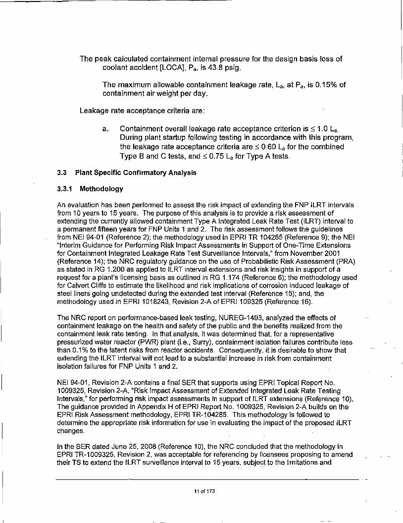
The peak calculated containment internal pressure for the design basis loss of coolant accident [LOCA], Pa, is 43.8 psig.
The maximum allowable containment leakage rate, La, at Pa, is 0.15% of containment air weight per day.
Leakage rate acceptance criteria are:
a. Containment overall leakage rate acceptance criterion is~ 1.0 La. During plant startup following testing in accordance with this program, the leakage rate acceptance criteria are ~ 0.60 La for the combined Type B and C tests, and ~ 0. 75 La for Type A tests.
3.3 Plant Specific Confirmatory Analysis
3.3.1 Methodology
An evaluation has been performed to assess the risk impact of extending the FNP ILRT intervals from 10 years to 15 years. The purpose of this analysis is to provide a risk assessment of extending the currently allowed containment Type A Integrated Leak Rate Test (ILRT) interval to a permanent fifteen years for FNP Units 1 and 2. The risk assessment follows the guidelines from NEI 94-01 (Reference 2); the methodology used in EPRI TR 104285 (Reference 9); the NEI "Interim Guidance for Performing Risk Impact Assessments in Support of One-Time Extensions for Containment Integrated Leakage Rate Test Surveillance Intervals," from November 2001 (Reference 14); the NRC regulatory guidance on the use of Probabilistic Risk Assessment (PRA) as stated in RG 1.200 as applied to ILRT interval extensions and risk insights in support of a request for a plant's licensing basis as outlined in RG 1.174 (Reference 6); the methodology used for Calvert Cliffs to estimate the likelihood and risk implications of corrosion induced leakage of steel liners going undetected during the extended test interval (Reference 15); and, the methodology used in EPRI 1018243, Revision 2-A of EPRI 109325 (Reference 16).
The NRC report on performance-based leak testing, NUREG-1493, analyzed the effects of containment leakage on the health and safety of the public and the benefits realized from the containment leak rate testing. In that analysis, it was determined that, for a representative pressurized water reactor (PWR) plant (i.e., Surry), containment isolation failures contribute less than 0.1 % to the latent risks from reactor accidents. Consequently, it is desirable to show that extending the ILRT interval will not lead to a substantial increase in risk from containment isolation failures for FNP Units 1 and 2.
NEI 94-01, Revision 2-A contains a final SER that supports using EPRI Topical Report No. 1009325, Revision 2-A, "Risk Impact Assessment of Extended Integrated Leak Rate Testing Intervals," for performing risk impact assessments in support of ILRT extensions (Reference 10). The guidance provided in Appendix H of EPRI Report No. 1009325, Revision 2-A builds on the EPRI Risk Assessment methodology, EPRI TR-104285. This methodology is followed to determine the appropriate risk information for use in evaluating the impact of the proposed ILRT changes.
In the SER dated June 25, 2008 (Reference 10), the NRC concluded that the methodology in EPRI TR-1009325, Revision 2, was acceptable for referencing by licensees proposing to amend their TS to extend the ILRT surveillance interval to 15 years, subjec~to the limitations and -
11 of173

conditions noted in Section 4.0 of the Safety Evaluation (SE). Table 3.3.1-1 addresses each of the four limitations and conditions for the use of EPRI 1009325, Revision 2.
Table 3.3.1-1, EPRI Report No. 1009325 Revision 2 Limitations and Conditions Limitation/Condition
(From Section 4.2 of SE) FNP Resconse 1. The licensee submits documentation indicating FNP PRA technical adequacy is addressed in
that the technical adequacy of their PRA is Section 3.3.2 of this submittal and Attachment 1, consistent with the requirements of RG 1.200 "Permanent ILRT Interval Extension Risk Impact relevant to the ILRT extension. Assessment," which addresses the Technical
Adequacy of the PRA modeling. 2.a The licensee submits documentation Since the ILRT does not impact core damage
indicating that the estimated risk increase frequency (GDF), the relevant criterion is large associated with permanently extending the early release frequency (LERF). The increase in ILRT surveillance interval to 15 years is small, LERF based on the internal events PRA, resulting and consistent with the clarification provided in from a change in the Type A ILRT test interval Section 3.2.4.5 of this SE. from three-in-ten years to one-in-fifteen years, is
conservatively estimated as 1. 75E-07 /year for Unit 1 and 1.60E-07/year for Unit 2, using the EPRI guidance. These estimated changes in LERF for FNP Units 1 and 2, while not "very small," are still determined to be within the acceptance guidelines of RG 1.174. [See Attachment 1, Section 7.0 of this submittal].
2.b Specifically, a small increase in population The change in Type A test frequency to once per dose should be defined as an increase in fifteen years, measured as an increase to the total population dose of less than or equal to either integrated plant risk for those accident sequences 1.0 person-rem per year or 1 % of the total influenced by Type A testing, based on the population dose, whichever is less restrictive. internal events PRA is 1.0BE-02 person-rem/year
for Unit 1 and 9.89E-03 person-rem/year for Unit 2. EPRI Report No. 1'009325, Revision 2-A, states that a very small population dose is defined as an increase of s 1.0 person-rem/year ors 1 % of the total population dose, whichever is less restrictive for the risk impact assessment of the extended ILRT intervals. This is consistent with the NRG Final SE for NEI 94-01 and EPRI Report No. 1009325 (Reference 10). Moreover, the risk impact when compared to other severe accident risks is negligible. [See Attachment 1, Section 7.0 of this submittal].
2.c In addition, a small increase in GGFP should The increase in the conditional containment failure be defined as a value marginally greater than probability from the three in ten year interval to a that accepted in a previous one-time 15-year permanent one time in fifteen-year interval is ILRT extension requests. This would require 0.92% for Unit 1 and 0.92% for Unit 2. EPRI that the increase in GGFP be less than or Report No. 1009325, Revision 2-A states that equal to 1.5 percentage point. increases in GGFP of
s 1.5 percentage points are very small. This is consistent with the NRG Final SE for NEI 94-01 and EPRI Report No. 1009325. Therefore, this increase is judged to be very small. [See Attachment 1 Section 7.0].
12of173

Table 3.3.1-1, EPRI Report No. 1009325 Revision 2 Limitations and Conditions Limitation/Condition
(from Section 4.2 of SEl FNP Resoonse 3. The methodology in EPRI Report No. The representative containment leakage for Class
1009325, Revision 2, is acceptable except for 3b sequences used by FNP is 100 La, based on the calculation of the increase in expected the recommendations in the latest EPRI report population dose (per year of reactor (Reference 20) and as recommended in the NRC operation). In order to make the methodology SE on this topic (Reference 9). It should be noted acceptable, the average leak rate accident that this is more conservative than the earlier case (accident case 3b) used by the licensees previous industry ILRT extension requests, which shall be 100 La instead of 35 La. utilized 35 La for the Class 3b sequences. [See
Attachment 1, Section 3.01 4. A licensee amendment request (LAR) is Adequate NPSH is available to the ECCS pumps
required in instances where containment over- assuming the maximum long-term suppression pressure is relied upon for ~mergency core pool temperature with no increase in containment cooling system (ECCS) performance pressure above that present prior to the
postulated LOCA. Refer to Section 3.1.3 of this submittal.
3.3.2 Technical Adequacy of the PRA
Technical adequacy of the PRA, synonymous with Probabilistic Safety Assessment (PSA) is presented in Attachment 1, Appendix A, of this submittal.
Internal Events PRA Quality Statement for Permanent 15-Year ILRT Extension
The FNP PRA modeling is highly detailed, including a wide variety of initiating events, modeled systems, operator actions, and common cause failure events. The PRA model quantification process used for the FNP PRA is based on the event tree and fault tree methodology, which is a well-known methodology in the industry.
The FNP PRA model is controlled in accordance with SNC procedure RIE-001, "Generation and Maintenance of Probabilistic Risk Assessment Models and Associated Updates, (Reference 29)" and associated guidelines. This procedure defines the process for implementing regularly scheduled and interim PRA model updates, for tracking issues identified as potentially affecting the PRA models (e.g., due to changes in the plant, errors or limitations identified in the model, industry operating experience, etc.), and for controlling the model and associated computer files. To ensure that the current PRA model remains an accurate reflection of the as-built, as-operated plants, RIE-001 requires that the following activities outlined in the procedure be routinely performed:
• Design changes and procedure changes are reviewed for their impact on the PRA model on an on-going basis
• Reliability data, unavailability data, initiating events frequency data, human reliability data, and other such PRA inputs shall be reviewed approximately every two fuel cycles and updated as necessary to maintain the PRA consistent with the as-operated plant.
Plant Changes Not Yet Incorporated into the PRA Model
As part of the PRA model configuration control, SNC maintains a PRA model maintenance database that tracks all issues that have been identified that could impact the FNP PRA model. The significance of the pending items in the database is evaluated to determine the impact on
13of173

model results. Each pending item is prioritized for future model updates according to its significance to model results.
Parts of the PRA Used
The ILRT risk assessment utilizes the overall Level 1 and Level 2 results from Reference 17, as noted in the main report of the ILRT risk assessment. Section 3.2.4.1 of the NRC final SE (Reference 10) of the EPRI ILRT risk assessment methodology documents that Capability Category I is appropriate since approximate values of Core Damage Frequency (CDF) and Large Early Release Frequency (LERF) and their distribution among release categories are sufficient for use in the EPRI methodology.
Risk Assessment Methodology Summary
The ILRT risk assessment methodology is based on EPRI TR-1018243 (Reference 16). The methodology as applied for FNP is fully described in the main report of the ILRT risk assessment.
PRA Key Assumptions and Approximations
For this application, the EPRI methodology involves a bounding approach to estimate the change in LERF for extending the ILRT interval. Rather than exercising the PRA model itself, the methodology involves the establishment of separate calculations that are linearly related to the plant CDF contribution that is not already LERF. The ILRT risk assessment methodology incorporates various assumptions and approximations identified in the main report of the ILRT risk assessment. Key EPRI methodology assumptions and approximations are addressed via sensitivity studies. Any assumptions and approximations utilized in the PRA are judged to have negligible impacts compared to those utilized in the EPRI methodology for the purposes of this application. Assessment of PRA model Technical Adequacy
Several assessments of technical capability have been made for the FNP Internal Events PRA models:
• An independent PRA peer review was conducted under the auspices of the Westinghouse Owners Group (WOG) in 2001, following the Industry PRA Review process.
• In 2005, a gap analysis was performed against the available version of the ASME PRA Standard (Reference 18) and RG 1.200, Revision 0.
The Farley Unit 1 Probabilistic Risk Assessment (PRA) Peer Review was performed in March of 201 O at the Southern Nuclear offices in Birmingham, AL, using the NEI 05-04 process (Reference 19), the 2009 version of the ASME/ANS PRA Standard (Reference 20), and RG 1.200, Revision 2 (Reference 7). The purpose of this review was to provide a method or establishing the technical adequacy of the PRA for the spectrum of potential risk-informed plant licensing applications for which the PRA may be used.
The 201 O FNP Unit 1 PRA Peer Review was a full-scope review of the Technical Elements of the internals events (including internal flooding), at-power PRA. The PRA reviewed for this Peer Review was the Revision 9 Version 1 of the FNP Unit 1 PRA model.
A summary of the peer review is described in the following information.
14 of173

• The ASME PRA Standard contains a total of 326 numbered supporting requirements in 14 technical elements and the configuration control element. Of the 326 SRs, eight (8) were determined to be not applicable to the FNP Unit 1 PRA.
• 17 "SR Not Met" have been addressed and closed. Table 1, "Resolution of the Farley PRA Peer Review F&Os Associated with the 17 Not Met SRs," of Attachment 1 of this submittal shows details of the 17 "SR Not Met" findings and resolutions after the peer review.
Conclusion:
The FNP Units 1 and 2 Internal Events PRA model is judged sufficient for the ILRT interval riskinformed application in accordance with RG 1.200, Revision 2.
External Events PRA Quality Statement for Permanent 15-Year ILRT Extension
In addition to the Internal Events PRA models used for this ILRT Risk Assessment, FNP has Fire PRA models for Units 1 and 2, which were developed for Risk Informed applications including National Fire Protection Association Standard 805 (NFPA 805), "Performance-Based Standard for Fire Protection for Light Water Reactor Electric Generating Plants, 2001 Edition."
The FNP Fire PRA models underwent a RG 1.200, Revision 2, peer review against the ASME PRA Standard, conducted by the Pressurized Water Reactor Owner's Group (PWROG) in October 2011 in accordance with NEI 07-12. The peer review concluded that the methodologies used in development of the FNP Fire PRA models were appropriate and sufficient to satisfy ASME/ANS PRA Standard RA-Sa-2009. The results of the Fire PRA peer review were included in the LAR submitted to the NRC for approval to transition to NFPA 805 (Reference 21).
In addition to the PWROG peer review, the NRC extensively reviewed the FNP Fire PRA as part of their review and audit of the FNP NFPA 805 LAR submittal. Following their review and approval of the license amendment, the NRC issued an SER (Reference 22), which noted that the disposition and closure of the Fire PRA peer review findings and observations (F&Os) are acceptable.
Based on the results of these reviews, the FNP Fire PRA meets the requirements of the AMSE PRA Standard and therefore is technically adequate and of sufficient quality for use in riskinformed applications. Although not used in the quantitative ILRT Risk Assessment, the Fire PRA CDF and LERF values for Units 1 and 2 are shown in Table 6.2 of Attachment 1 of this submittal, which provides a summary of the contributions of the FNP Internal Events, Fire Events and other External Events models to the total CDF and LERF for each unit.
3.3.3 Summary of Plant-Specific Risk Assessment Results
The findings of the FNP Risk Assessment contained in Attachment 1 confirm the general findings of previous studies that the risk impact associated with extending the ILRT interval from three-inten years to one-in-15 years is small. The FNP plant-specific results for extending ILRT interval from the current 1 O years to 15 years are summarized below:
Based on the results from Attachment 1 of this submittal, Section 5, "Results," and the sensitivity calculations presented in Attachment 1, Section 6, "Sensitivities," the following conclusions
15 of173

regarding the assessment of the plant risk associated with permanently extending the Type A ILRT test frequency to fifteen years are:
• RG 1.17 4, (Reference 6) provides acceptance criteria for increase in CDF and LERF resulting from a risk-informed application. Since the ILRT does not impact CDF, the relevant criterion for this application is LERF. When the calculated increase in LERF is "very small," which is taken as being less than 1.0E-7 per reactor-year, the change will be generally considered acceptable irrespective of the plant's LERF value. When the calculated increase in LERF is in the range of 1.0E-7 per reactor-year to 1.0E-6 per reactor-year, the applications will be considered acceptable only if the total plant LERF is less than 1.0E-5 per reactor-year. The increase in LERF based on the internal events PRA, resulting from a change in the Type A ILRT test interval from three-in-ten years to one-in-fifteen years, is conservatively estimated as 1.75E-07/yr for Unit 1 and 1.60E-07/yr for Unit 2, using the EPRI guidance as written. These estimated changes in LERF for FNP Units 1 and 2, while not "very small," are still determined to be within the acceptance guidelines of RG 1.17 4, since the plants' LERF values from the internals events PRA are below 1.0E-5 per reactor-year.
• A sensitivity analysis was performed to evaluate the impact of the ILRT application on both internal and external events PRA results. RG 1.17 4 (Reference 6) states that applications that result in increases to LERF above 1.0E-6 per reactor-year would not normally be considered. Both these values are slightly over the RG 1.17 4 acceptance criteria value of 1.0E-6. However. as explained in Section 6.3. When the PRA is revised later in 2016 taking credit for the Generation Ill RCP shutdown seals which are already installed, the plant CDF and LERF values are expected to be significantly lower and similarly the increase in LERF values attributable to ILRT will be considerably lower and below the 1.0E-6 threshold, thus meeting the RG 1.174 criteria.
• According to RG 1.17 4, although the proposed changes to ILRT do not change the CDF values, no changes would be permitted per this RG if the plant CDF exceeds 1.0E-4 per year. For the sensitivity case of the examination of the impact of external events. the calculated CDF. with the external events included. the CDF for Unit 2 is 1.02E-4 per year. which is slightly higher than this value. However. as explained in Section 6.3. when the PRA is revised later in 2016 taking credit for the Generation Ill RCP shutdown seals, which are already installed, the plant CDF is expected to be significantly below the 1.0E-4 per year threshold.
• The change in Type A test frequency to once-per-fifteen years, measured as an increase to the total integrated plant risk for those accident sequences influenced by Type A testing, based on the internal events PRA, is 1.0BE-02 person-rem/yr for Unit 1 and 9.89E-03 person-rem/yr for Unit 2. EPRI Report No. 1009325, Revision 2-A states that a very small population dose is defined as an increase of ::;; 1.0 person-rem per year or ::;; 1 % of the total population dose, whichever is less restrictive for the risk impact assessment of the extended ILRT intervals. This is consistent with the NRC Final Safety Evaluation for NEI 94-01 and EPRI Report No. 1009325 (Reference 16). Moreover, the risk impact when compared to other severe accident risks is negligible.
• The increase in the conditional containment failure probability from the three-in- ten-year interval to a permanent one time in fifteen-year interval is 0.92% for Unit 1 and 0.92% for Unit 2. EPRI Report No. 1009325, Revision 2-A, states that increases in CCFP of ::;; 1.5 percentage points are very small. This is consistent with the NRC Final SE for NEI 94-01
16of173

and EPRI Report No. 1009325 (Reference 16). Therefore, this increase is judged to be very small.
Therefore, permanently increasing the ILRT interval to fifteen years is considered to be a very small change to the FNP Units 1 and 2 risk profiles.
3.3.4 Previous Assessments
The NRG in NUREG-1493 (Reference 8) has previously concluded the following:
• Reducing the frequency of Type A tests (ILRTs) from three per ten years to one per twenty years was found to lead to an imperceptible increase in risk. The estimated increase in risk is very small because ILRTs identify only a few potential containment leakage paths that cannot be identified by Types B and C testing, and the leaks that have been found by Type A tests have been only marginally above existing requirements.
• Given the insensitivity of risk to containment leakage rate and the small fraction of leakage paths detected solely by Type A testing, increasing the interval between integrated leakage rate tests is possible with minimal impact on public risk. Beyond testing the performance of containment penetrations, ILRTs also test the integrity of the containment structure.
The findings for FNP confirm these general findings on a plant specific basis considering the severe accidents evaluated for Farley Units 1 and 2, the Farley Units 1 and 2 containment failure modes, and the local population surrounding Farley Units 1 and 2.
Details of the FNP risk assessment are contained in Attachment 1 of this submittal.
3.4 Non-Risk Based Assessment
Consistent with the defense-in-depth philosophy discussed in RG 1.174, FNP has assessed other non-risk based considerations relevant to the proposed amendment. FNP has multiple inspection and testing programs that ensure the containment structure remains capable of meeting its· design functions and that are design to identify any degrading conditions that might affect that capability. These programs are discussed below.
3.4.1 Nuclear Coatings Program
The FNP Nuclear Coatings Program performs inspections on coatings in areas inside the reactor containment where coating failure could adversely affect the operation of post-accident fluid systems and, thereby, impair safe shutdown.
The general containment walk-down is performed every outage and completed as soon as possible in the beginning of the outage to ensure that deficient coating areas can be repaired or left in a safe condition prior to start up. After the walk-down, thorough visual inspections are carried out on previously designated areas and on areas noted as deficient during the last inspection. During the inspection, coated surfaces are visually examined for any visible conditions such as blistering, cracking, flaking/peeling, rusting and physical damage. For coating surfaces determined to be suspect, defective or deficient, physical tests such as dry film thickness and adhesion testing may be performed when directed by the evaluator, program engineer/nuclear specialist or program owner.
17of173
Unqualified or degraded coatings found during an inspection are documented in the site Unqualified/Degraded Coating Log, which is maintained as a quality record. Areas removed from the Unqualified/Degraded Coating Log will be documented with the reason for removal along with an associated Condition Report or work order (WO).
Unqualified I Degraded Coatings in Containment
The FNP Nuclear Coatings Program requires a log of the amount of unqualified coatings within containment to be maintained. During the most recent FNP-1 coatings inspections performed during the 1 R26 refueling outage, the current amount of unqualified coatings reported in the Unqualified Coatings Log is 51.5 square ft against a margin of 856.5 square ft. During the most recent FNP-2 coatings inspections performed during the 2R24 refueling outage, the current amount of unqualified coatings reported in the Unqualified Coatings Log is 13.5 square ft against a margin of 812 square ft.
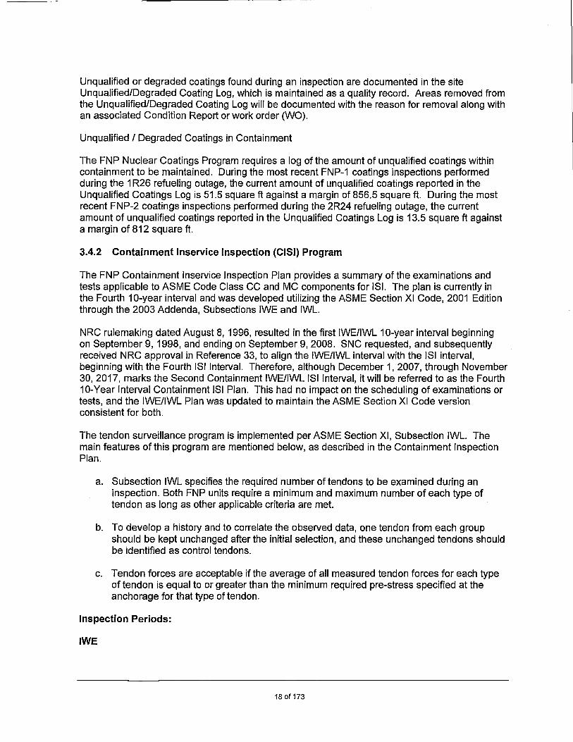
3.4.2 Containment lnservice Inspection (CISI) Program
The FNP Containment lnservice Inspection Plan provides a summary of the examinations and tests applicable to ASME Code Class CC and MC components for ISi. The plan is currently in the Fourth 10-year interval and was developed utilizing the ASME Section XI Code, 2001 Edition through the 2003 Addenda, Subsections IWE and IWL.
NRG rulemaking dated August 8, 1996, resulted in the first IWE/IWL 10-year interval beginning on September 9, 1998, and ending on September 9, 2008. SNC requested, and subsequently received NRG approval in Reference 33, to align the IWE/IWL interval with the ISi interval, beginning with the Fourth ISi Interval. Therefore, although December 1, 2007, through November 30, 2017, marks the Second Containment IWE/IWL ISi Interval, it will be referred to as the Fourth 10-Year Interval Containment ISi Plan. This had no impact on the scheduling of examinations or tests, and the IWE/IWL Plan was updated to maintain the ASME Section XI Code version consistent for both.
The tendon surveillance program is implemented per ASME Section XI, Subsection IWL. The main features of this program are mentioned below, as described in the Containment Inspection Plan.
a. Subsection IWL specifies the required number of tendons to be examined during an inspection. Both FNP units require a minimum and maximum number of each type of tendon as long as other applicable criteria are met.
b. To develop a history and to correlate the observed data, one tendon from each group should be kept unchanged after the initial selection, and these unchanged tendons should be identified as control tendons.
c. Tendon forces are acceptable if the average of all measured tendon forces for each type of tendon is equal to or greater than the minimum required pre-stress specified at the anchorage for that type of tendon.
Inspection Periods:
IWE
18of173

The examinations and tests required by IWA and IWE will be completed during each inspection interval for the service lifetime of the plant. In accordance with ASME Section XI, IWA-2400, FNP has elected to perform these examinations under Inspection Program 8 of IWA-2400 and IWE-2400. This inspection program is defined as:
• Expedited Examination Period (pre-service/first period of the first interval) from September 9, 1996, to September 8, 2001
• First Containment Inspection Interval - End date modified for the First Containment Inspection Interval to coincide with the end date for the third ISi interval, i.e., November 30, 2007
• Fourth Inspection ISi Interval -The 10 years following the 1st Containment Inspection Interval, i.e., December 1, 2007, to November 30, 2017
• Fifth Inspection Interval - The 10 years following the Second Containment inspection Interval, i.e., December 1, 2017, to November 30, 2027, and
• Sixth Inspection Interval - The 10 years following the Third Containment inspection Interval, i.e., December 1, 2027, to November 30, 2037
NOTE: The first containment inspection interval was to end on September 8, 2008; however, SNC was granted approval to align the containment inspection interval with the ISi interval (Reference 33). The ISi interval and the containment inspection interval were updated and began on December 1, 2007, and the containment interval is now referred to as the Fourth 10-Year Interval Containment ISi Plan.
Reportability Summary:
The following conditions are required to be reported in the ISi Summary Report required by IWA-6000 (Form NIS-1):
• Reference: 10 CFR 50.55a(b)(2)(ix)(A) - If a condition exists in an accessible area for Class MC that could indicate the presence of, or result in, degradation to inaccessible areas, then the report must address: (1) a description of the type and estimated extent of degradation, and the conditions that led to the degradation; (2) an evaluation of each area, and the result of the evaluation, and; (3) a description of necessary corrective actions.
• Reference: 1 O CFR 50.55a(b)(2)(viii)(E) - If a condition exists in an accessible area for Class CC that could indicate the presence of, or result in, degradation to inaccessible areas then the report must address: (1) a description of the type and estimated extent of degradation, and the conditions that led to the degradation; (2) an evaluation of each area, and the result of the evaluation, and; (3) a description of necessary corrective actions.
The ISi Summary Report (NIS-1 or OAR-1) is required to be submitted to the NRC within 90-days of the end of each RFO. IWL examinations are typically not performed during RFOs. Therefore, any report required by IWL will be included in the ISi Summary Report for the RFO following completion of the IWL examinations.
19of173

IWL
The examinations and tests required by IWA and IWL will be completed during each inspection interval for the service lifetime of the plant. The frequency of the concrete containment examination for a particular unit is every 5 years in accordance with IWL-2410(a). The examinations required by IWL-2524 and IWL-2525 shall be performed on a 5-year frequency (±1 year) for the service lifetime of the plant. The examinations required by IWL-2522 and IWL-2523 for a particular unit will be every 1 O years.
IWE Components Subject to Examination:
The scope of examinations is based on ASME Section XI, Table IWE-2500-1 and contains the examination category E-A, Containment Surfaces, and E-C, Containment Surfaces Requiring Augmented Examination.
Category E-A, Item E1.10 - Containment Vessel Pressure Retaining Boundary
Components utilized in the design of FNP's Containment are scoped into the IWE Program under item E1.10, which are the accessible surface of the liner and pressure-retaining bolting. These items have been listed out in Tables 3.4.2-1 and 3.4.2-2. Beginning with the 2R21 and the 1 R24 outages, FNP included the reactor cavity as part of the IWE scope. Until the spring of 2011, FNP did not include this area in its scope of examinations since it was not understood to be a part of the examination scope. This is discussed in further detail in Section 3.6 of this submittal.
Category E-A, Item E1 .30 - Moisture Barriers
Components considered to be part of the moisture barrier are materials that are intended to prevent intrusion of moisture against in accessible areas of the liner plate. The FNP moisture barrier is located along the periphery of containment where the vertical portion of the liner and the concrete fill slab meet on the 105 ft elevation. The moisture barrier is also provided on both sides along the periphery of the secondary shield wall, radially between the outer containment wall and the reactor vessel shield wall, and expansion joints between the fill slab and footings for equipment like the steam generators and RCPs.
Beginning with the 2R23 and 1 R26 outages, FNP included the leak chase test connections (LCTCs) as part of the IWE scope. Prior to the spring of 2012, FNP did not have these items scoped under the IWE Program or the Containment Inspection Program; essentially these items were not recognized as a potential location for moisture intrusion to the inaccessible portions of the liner plate. Following the 1 R24 outage in spring 2012, the LCTCs were added to the Containment Inspection Plan as an Augmented Examination for both units. Subsequent to the issuance of IN 2014-07 in May 2014, FNP added the LCTCs to the IWE Program as moisture barriers.
, Beginning with the 2R23 and 1 R26 outages, FNP has scoped in a section of the moisture barrier that was previously excluded from the Containment Inspection Program, but was recognized as a "generic" moisture barrier not under the scope of Subsection IWE. This section of the moisture barrier is sealant that prevents moisture intrusion to inaccessible portions of the liner plate at concrete-to-concrete interfaces. During 2R23, an evaluation was performed to document the need to include this moisture barrier under the scope of IWE. Prior to 2R23 and 1 R26, FNP began inclusion of the concrete-to-concrete interfaces under an owner-elected scope based on results of a review performed under a technical evaluation. The review of the containment design
20of173

for areas where moisture could make its way to the inaccessible portions of the liner plate failed to identify these concrete-to-concrete expansion joints as potential locations. Additionally, the design drawings for the moisture barrier do not identify a sealant material. A replacement material for the moisture barrier was identified when a section of the moisture barrier needed to be replaced due to damage found during examination. The replacement material was indicated to be Thiokol T-2282.
21 of 173

Unit 1 Containment Inspection Schedule Table 3.4.2-1 Unit 1 IWE Examination Schedule
December 1, 2007 - December 1, 2010 • December 1, 2014 -
Examination Area November 30, 2010 November 30, 2014 November 30, 2017 First Period of the 4th Second Period of the 4th Third Period of the 4th
ISi Interval 1R22/1R23 ISi Interval 1 R24 / 1 R25 ISi Interval 1 R26 / 1 R27 Reactor Cavity Area'"' (Containment 1R24!5l!5l x liner in the reactor cavity) 105' Elevation 0° - go 0
'"1 1R221
"1 1 R251
"1
x
105' Elevation go0 - 180°'-' 1R22'' 1R25'-' x
105' Elevation 180° - 270°'-' 1R22 ., 1R25'-' x
Item E1.11 105' Elevation 210° • 360°'"1 1R22 "1 1R25'" x
(ASME Table 12g• Elevation 0° - go 0'"
1 1R22'"1 1R25'"1 x
IWE-2500-1) 12g• Elevation go 0 - 180°1
•1 1R221
"1 1R251
"1
x
Accessible 12g• Elevation 180° - 210°1•
1 1R22 ., 1R251"
1 x
Surface Areas 12g• Elevation 270° - 360°'-' 1R22"' 1R25'-' x
(Refer to Note 155' Elevation 0° - go 0'"' 1R22 ., 1R25'"' x
1 of Table 155' Elevation go0 - 180°'"' 1R22 "1 1R25'"1
x
3.4.2-3, 155' Elevation 180° - 270°'"1 1R221"
1 1R25'"1 x
Category E-A) 155' Elevation 270° - 360°'"1 1R221"
1 1R25'"1 x
Above 155' Elevation 0° .go 01• 1 1R221
"1 1 R241
"1
x
Above 155' Elevation go 0 - 180°'"' 1R22 ., 1 R24'"' x
Above 155' Elevation 180° - 270°'"' 1R22 ., 1R24'"' x
Above 155' Elevation 270° - 360°'"' 1R22'1 1R24'"1 x
Item E1.11 (ASME Table IWE-2500-1) Pressure VT-3, VT-1 of any bolted VT-3, VT-1 of any bolted VT-3, VT-1 of any bolted Retaining Bolting connection disassembled connection disassembled connection disassembled
Electrical Penetration Q1T52-Boog-A x1•1
Electrical Penetration Q1152-8011-B x,-,
Penetration-14 X'"' Penetration-71 X'"' Penetration-72 X'"' Penetration-go x1·1
Penetration-g2 x1·1
Notes: In addition to the periodic examination required by Item E1.11,100% of accessible bolted connections must be VT-3 examined, once each interval, per 1 OCFR50.55a(b)(2)(ix)(G). Flaws or degradation identified during the performance of the VT-3 examination must be examined in accordance with the VT-1 examination method. Examinations are to be performed when the connection is disassembled but may be performed in place, under tension when disassembly is not otherwise reauired durina the insoection interval. Examination of the boltina for each connection is required onlv once each inspection interval.
22of173

Unit 1 Containment Inspection Schedule Table 3.4.2-1 Unit 1 IWE Examination Schedule
uecemoer 1, 2007 - December 1, 2010 - December 1, 2014 -Examination Area November 30, 2010 First November 30, 2014 November 30, 2017 Third
Period of the 4th ISi Second Period of the 4th Period of the 4th ISi Interval 1 R22 / 1 R23 ISi Interval 1 R24 / 1 R25 Interval 1R26/1R27
Moisture Barrier 0°-360° (Caulking, Flashim:i and other Sealant)
1R22(4) x x Leak Chase Test Connection - 1 1 R25101 x Leak Chase Test Connection - 2 1 R25101 x Leak Chase Test Connection - 3 1R24 1R25'"' x Leak Chase Test Connection - 4 1R25'"' x Leak Chase Test Connection - 5 1R24 1 R251
"1 x
Leak Chase Test Connection - 6 1 R25101 x Leak Chase Test Connection - 7 1R25'01 x Leak Chase Test Connection - 8 1R25'01 x Leak Chase Test Connection - 9 1R25'01 x Leak Chase Test Connection - 10 1 R25'01 x
Item E1.30 Leak Chase Test Connection - 11 1 R25'01 x Leak Chase Test Connection - 12 1 R25'01 x
~ASME Table Leak Chase Test Connection - 13 1R25101 x WE-2500-1) Leak Chase Test Connection - 14 1 R25'01 x Moisture
Barriers (Refer Leak Chase Test Connection -15 1 R25'"' x to Note 3 of Leak Chase Test Connection - 16 1 R25'"1 x
Table 3.4.2-3 Leak Chase Test Connection - 17 1 R25'"' x Category E-A) Leak Chase Test Connection -18 1 R25101 x
(Refer to - Leak Chase Test Connection - 19 1 R25101 x Appendix B for Leak Chase Test Connection - 20 1 R25101 x information on Leak Chase Test Connection - 21 1 R25'01 x
LCTC Leak Chase Test Connection - 22 1 R25'"' x location) Leak Chase Test Connection - 23 1 R25'01 x Leak Chase Test Connection - 24 1 R25'01 x Leak Chase Test Connection - 25 1 R25'01 x Leak Chase Test Connection - 26 1 R25'01 x Leak Chase Test Connection - 27 1 R25'01 x Leak Chase Test Connection - 28 1 R25'"' x Leak Chase Test Connection - 29 1R25'"' x Leak Chase Test Connection - 30 1 R25101 x Leak Chase Test Connection - 31 1 R25'01 x Leak Chase Test Connection - 32 1 R25'"' x Leak Chase Test Connection - 33 1 R251
"1 x
Leak Chase Test Connection - 34 1 R25101 x Leak Chase Test Connection - 35 1 R25101 x
23of173

Unit 1 Containment Inspection Schedule Table 3.4.2-1 Unit 1 IWE Examination Schedule
uecember 1, 2007 - December 1, 2010 - December 1, 2014 -
Examination Area November 30, 2010 First November 30, 2014 November 30, 2017 Third Period of the 4th ISi Second Period of the 4th Period of the 4th ISi Interval 1R22/1 R23 ISi Interval 1 R24 / 1 R25 Interval 1R26/1R27
Leak Chase Test Connection - 36 1R25''' x Leak Chase Test Connection - 37 1 R25'"' x Leak Chase Test Connection - 38 1R24 1 R25''' x Leak Chase Test Connection - 39 1 R25''1 x Leak Chase Test Connection - 40 1R24 1R25''' x
Item E1.30 Leak Chase Test Connection -41 1 R25''1 x Leak Chase Test Connection - 42 1 R25'"' x (ASMETable Leak Chase Test Connection - 43 1R25''' x IWE-2500-1) Leak Chase Test Connection - 44 1R25'"' x Moisture
Barriers (Refer Leak Chase Test Connection - 45 1R25''' x to Note 3 of Leak Chase Test Connection - 46 1 R25''' x Table 2.1 Leak Chase Test Connection - 47 1R25''' x
Category E-A) Leak Chase Test Connection - 48 1R25''1 x (Refer to- Leak Chase Test Connection - 49 1R25''' x
Appendix B for Leak Chase Test Connection - 50 1 R25''1 x information on Leak Chase Test Connection - 51 1 R25'"' x
LCTC Leak Chase Test Connection - 52 1R25'"' x location) Leak Chase Test Connection - 53 1R25'"' x Leak Chase Test Connection - 54 1 R25''' x Leak Chase Test Connection - 55 1R25 "' x Leak Chase Test Connection - 56 1R25''1 x Leak Chase Test Connection - 57 1R25''' x Leak Chase Test Connection - 58 1 R25''' x
NOTES:
(1) Deleted (2) Scheduled during the last outage of this interval if it has not previously been performed during the interval. Examinations are
to be performed when the connection is disassembled; however, they may be performed in place, under tension, when disassembly is not otherwise required during the inspection interval. The VT-3 examination of the bolting is required only once each inspection interval.
(3) Bolted connections that are disassembled during the scheduled General Visual Examinations, must be examined using the VT-3 method. Flaws or degradation identified via the VT-3 examinations must also be examined using the VT-1 method. Material specifications IWB-3517-1 must be used to evaluate the flaws or degradation.
(4) WO 1090680901 provides the full report for the 1 R22 IWE evaluations.
24Of173

(5) WO SNC64083 provides the 1 R24 exams. (6) Perform the General Visual examination of the cavity liner in the RPV sump as proposed by CR 201103645. (7) Perform the General Visual examination of the Containment leak chase test connections as part of the moisture barrier as
required by CAR194863. Examination shall be conducted in accordance with Table IWE-2500-1. (8) The General Visual of the liner plate in the reactor cavity should be performed at the same time the BM ls of the RPV are
performed. (9) Refer to WO SNC 435880 I SNC 503935 for the full 1 R25 IWE report.
25of173

Unit 2 Containment Inspection Schedule Table 3.4.2-2 Unit 2 IWE Examination Schedule
December 1, 2007- December 1, 2010 - December 1, 2014 -November 30, 2010 November 30, 2014 November 30, 2017
Examination Area First Period of the 4th Second Period of the 4th Third Period of the 4•h ISi intervai 151 Interval 151 Interval 2R19/2R20 2R21/2R22/2R23 2R24/2R25
Reactor Cavity Area "'"' (CO!Jtaiflb'il~~\ liner in the reactor 2R21 x cavitvl' 105' Elevation 0° - go 0
" 2R20'"' 2R23 ., x 105' Elevation go 0
- 1 B0° '""' 2R20'"' 2R23 '' x 105' Elevation 1 B0° - 210° .,.. 2R20'"' 2R23' '' x
Item E1.11 105' Elevation 270° - 360°"""' 2R20'"' 2R23' '' x (ASMETable 12g• Elevation 0° - go 0
.,.., 2R20'"' 2R23 ., x IWE-2500-1) 12g• Elevation go 0
- 180° 2R20'"' 2R23 ., x Accessible 12g• Elevation 1 B0° - 270° '""' 2R20'"' 2R23 ., x
Surface Areas 12g• Elevation 270° - 360° '""' 2R20'"' 2R23 ''' x (Refer to Note 155' Elevation 0° - go 0
' '""' 2R20'"' 2R23' '' x 1 of Table 2.1, 155' Elevation go0
- 1 B0°''""' 2R20'"' 2R23' ' x Category E-A) 155' Elevation 1 B0° - 270° 2R20'"' 2R23' ., x
155' Elevation 270° - 360° 2R20'"' 2R23 ., x Above 155' Elevation 0° .go 0
'""' 2R20'"' 2R23 ., x Above 155' Elevation go 0
- 1 B0° " 2R20'"' 2R23 ., x Above 155' Elevation 180° - 270°'·· 2R20'"' 2R23 '' x Above 155' Elevation 270° - 360°'·"' 2R20'"' 2R23' '' x
Item E1 .11 (ASME Table IWE-2500-1) Pressure VT-3, VT-1 of any bolted VT-3, VT-1 of any bolted VT-3, VT-1 of any bolted Retaininq Boltinq connection disassembled connection disassembled connection disassembled
Electrical Penetration Q2T52-BOOg-A x·-· Electrical Penetration Q2T52-B011-B X'"'
Penetration-14 X'"' Penetration-71 X'"' Penetration-72 X'"' Penetration-go x·-· Penetration-g2 X'"'
Notes: In addition to the periodic examination required by Item E1 .11, 100% of accessible bolted connections must be VT-3 examined, once each interval, per 1DCFR50.55a(b)(2)(ix)(G). Flaws or degradation identified during the performance of the VT-3 examination must be examined in accordance with the VT-1 examination method.
Examinations are to be performed when the connection is disassembled but may be performed in place, under tension when disassembly is not otherwise required during the inspection interval. Examination of the bolting for each connection is required only once each inspection interval.
26of173

unit 2 Containment Inspection Scneaule Table 3.4.2-3 Unit 2 IWE Examination Schedule
uecemoer 1, ..::uu1 - uecemoer 1, :lU1 u - uecemoer 1, .:u , .. -
Examination Area November 30, 201~ November 30, 2014 November 30 2017 First Period of the 4 h Second Period of the 4lh Third Period o# the 4•h
ISi Interval 2R19 / 2R20 ISi Interval 2R21/2R22/2R23 ISi Interval 2R24/2R25 Moisture Barrier 0°-360° (Caulking, 2R20<5l 2R22<10l x Flashina and other Sealant) Leak Chase Test Connection - 1 2R22''ul x Leak Chase Test Connection - 2 2R221 'ul x Leak Chase Test Connection - 3 2R22 OV/ x Leak Chase Test Connection - 4 2R221'uJ x Leak Chase Test Connection - 5 2R22 OV/ x Leak Chase Test Connection - 6 2R22''ul x Leak Chase Test Connection - 7 2R22''v' x Leak Chase Test Connection - 8 2R22 OV/ x Leak Chase Test Connection - 9 2R221 'vl x Leak Chase Test Connection - 10 2R22 OV/ x
Item E1.30 Leak Chase Test Connection - 11 2R22"u' x Leak Chase Test Connection - 12 2R22 Ovi x (ASME Table Leak Chase Test Connection - 13 2R22''u1 x IWE-2500-1) Leak Chase Test Connection - 14 2R22 OV/ x Moisture
Barriers (Refer Leak Chase Test Connection -15 2R22''uJ x to Note 3 of Leak Chase Test Connection - 16 2R22''v' x Table 2.1 Leak Chase Test Connection -17 , 2R221 'u1 x
Category E-A) Leak Chase Test Connection - 18 2R22''v' x (Refer to - Leak Chase Test Connection - 19 2R22' UJ x
Appendix B for Leak Chase Test Connection - 20 2R22''v' x information on Leak Chase Test Connection - 21 2R221 'v' x
LCTC Leak Chase Test Connection - 22 2R22''v' x location) Leak Chase Test Connection - 23 2R22 ovJ x Leak Chase Test Connection - 24 2R22' U/ x Leak Chase Test Connection - 25 2R22''v' x Leak Chase Test Connection - 26 2R22''v' x Leak Chase Test Connection - 27 2R221 'v' x Leak Chase Test Connection - 28 2R22 OV/ x Leak Chase Test Connection - 29 2R22''ul x Leak Chase Test Connection - 30 2R22 OV/ x Leak Chase Test Connection - 31 2R221 'ul x Leak Chase Test Connection - 32 2R22''vJ x Leak Chase Test Connection - 33 2R22 •vi x Leak Chase Test Connection - 34 2R22''vl x Leak Chase Test Connection - 35 2R22''v' x
27of173

Umt 2 Containment Inspection ~cneaule Table 3.4.2-3 Unit 2 IWE Examination Schedule
Examination Area uecemoer 1, "uu1 -November 30, 201~
First Period of the 4 h
uecemoer 1, 2010 -November 30, 2014
Second Period of the 4th
uecemoer 1, "u-14 -November 30 2017
Third Period ol the 4•h ISi Interval 2R19 / 2R20 ISi Interval 2R21/2R22/2R23 ISi Interval 2R24/2R25
Leak Chase Test Connection - 36 2R22 ,_, x Leak Chase Test Connection - 37 2R22\'"I x Leak Chase Test Connection - 38 2R22\'UJ x Leak Chase Test Connection - 39 2R22'' 01 x Leak Chase Test Connection - 40 - - 2R22 'ul - x
Item E1.30 Leak Chase Test Connection - 41 2R221'01 x (ASME Table Leak Chase Test Connection - 42 2R22''"1 x IWE-2500-1)
Leak Chase Test Connection - 43 2R22''u1 x Moisture Barriers (Refer ·Leak Chase Test Connection - 44 2R22''ul x
to Note 3 of Leak Chase Test Connection - 45 2R22 '"' x Table 2.1 Leak Chase Test Connection - 46 2R22' UJ x
Category E-A) Leak Chase Test Connection - 47 2R22''u1 x (Refer to - Leak Chase Test Connection - 48 2R22' UJ x
Appendix B for Leak Chase Test Connection - 49 2R22''ul x information on Leak Chase Test Connection - 50 2R22''ul x
leak chase Leak Chase Test Connection - 51 2R22''"1 x test Leak Chase Test Connection - 52 2R22''ul x connection location) Leak Chase Test Connection - 53 2R22'' I x
Leak Chase Test Connection - 54 2R22' UJ x Leak Chase Test Connection - 55 2R22''ul x Leak Chase Test Connection - 56 2R22''ul x Leak Chase Test Connection - 57 2R22'' 01 x Leak Chase Test Connection - 58 2R22 'ul x
28of173

--------------- ---- -
l'IU I t.::i: (1l Deleted. (2 Scheduled during the last outage of this interval if it has not previously been performed during the interval. Examinations are to be
performed when the connection is disassembled; however, they may be performed in place, under tension, when disassembly is not otherwise required during the inspection interval. The Vf-3 examination of the bolting is required only once each inspection interval.
(3) Bolted connections that are disassembled during the scheduled General Visual Examinations, must tle examined using the Vf-3 method. Flaws or degradation identified via the Vf-3 examinations must also be examined using the Vf-1 method. Material specifications IWB-3517/1 must be used to evaluate the flaws or degradation. Deleted. WO 2090232401 provides the full report for 2R20 IWE evaluations. Perform the General Visual examination of the cavity liner in the RPV sump as proposed by CR 201103645. Perform the General Visual examination of the Containment leak chase test connections as part of the moisture barrier as required by CAR 194863. Examination shall be conducted in accordance with Table IWE-2500-1.
r8l Repaired via WO 2053128401 during 2R19. 9 The General Visual of the liner plate m the reactor cavity should be performed at the same time the BM ls of the RPV are performed. 11 o1n Refer to WO SNC344240 for 2R22 exams. I) Refer to WO SNC390115 for exams performed in 2R23.
29Of173

IWE Exemption Criteria
Certain Class MC components are exempt from examination. The following criteria will be applied to components exempt from visual and volumetric examination and testing in accordance with ASME Section XI:
Table 3.4.2-4 Exemption Criteria Reference
Vessels (including RHR and CS encapsulation vessels), parts and appurtenances outside the boundaries of the containment system as defined IWE-1220 in the Design Specifications.
Embedded or inaccessible portions of containment vessels, parts and IWE-1220
appurtenances that met the requirements of the original Construction Code.
Portions of the containment vessels, parts, and appurtenances that become embedded or inaccessible as a result of vessel repair/replacement activities IWE-1220 if the conditions of IWE-1232(a) and (b) and IWE-5220 are met.
Piping, pumps and valves that are part of the containment system, or which - -IWE-1220---penetrate-or-are-attached to the-containment vesse1.--- -- -- - - - --- -
General Visual Examinations
General visual examinations shall be performed either directly or remotely by line of sight from available viewing angles from floors, platforms, walkways, ladders or other permanent plant vantage points, unless temporary access is required by the inspection plan. The visual examinations shall be performed with adequate illumination sufficient to detect evidence of degradation. Unless otherwise specified, resolution of the VT-2 character card height (0.158 in.) is considered sufficient.
It is SNC's position that a VT-3 visual examination can be performed in lieu of a general visual examination since the criteria for VT-3 are more stringent.
Detailed Visual Examinations
It is SNC's position that a VT-1 visual examination will be performed for a detailed visual examination since the Code is silent on the requirements and allows the Responsible Individual to determine what criteria should be met.
Augmented Examination and Supplemental Examinations
Areas meeting the selection criteria of IWE-1240 will receive augmented examination. Areas may be added as conditions warrant and also may be removed from Augmented Examination status as permitted by IWE-2420(c). Results of augmented examinations in accessible areas will be evaluated for their potential to affect inaccessible areas. The results of this evaluation will determine the scope and extent of augmented examinations in the inaccessible areas.
IWE-1241 requires areas likely to experience accelerated degradation and aging to be subject to the augmented examinations specified in Table IWE-2500-1, Category E-C. Item E4.10 requires detailed visual examination (VT-1) and volumetric examination (UT) of areas exhibiting signs of accelerated degradation of areas having conditions, which could cause accelerated degradation. Currently, there are no areas exhibiting these conditions.
30of173

Owner Elected Examinations
No examinations have been identified at this time.
IWL Components Subject to Examination
The scope of examinations is based on ASME Section XI, Table IWL-2500-1 and contains examination categories L-A, Concrete, and L-B, Unbonded Post-Tensioning System.
·This testing plan satisfies the programmatic requirements of the following section of the FNP TS:
• 5.5.6, Pre-stressed Concrete Containment Tendon Surveillance Program
L-A Concrete
_ . -----· -· ·---· ltem_L 1--11-requires_a_GeneraLVisual Examination.of-the-accessible exterior concrete-surface-of--~-· ·- ---- --the containment building. This examination is required once every five years per IWL-2410.
Accessible grease caps will be inspected during this concrete exam to detect grease leakage or grease cap deformation. In accordance with 1 O CFR 50.55a(b)(viii)(A), grease caps will be removed for this examination when there is evidence of tendon and grease cap deformation that indicate deterioration of anchorage hardware.
Item L 1.12 requires a detailed visual examination, at the discretion of the Responsible Engineer, of suspect areas that were identified during the general visual examination.
Item L 1.12 includes concrete surfaces at tendon anchorage areas.
NOTE: Concrete is pressure tested only after repair and replacement activities (IWL-5210). When pressure tested, it follows the rules of subsection IWE (see IWL-5230).
L-B Unbonded Post-Tensioning System
Item L2.10 requires measurement of the tendon pre-stressing force. Item L2.20 requires removal of a single wire from one tendon of each type for testing. Item L2.30 requires a detailed visual (VT-1) examination of the tendon anchorage components. Items L2.40 and L2.50 require laboratory analysis of the corrosion protection medium including any free water found.
Additional requirements for the post-tensioning system are specified in 1 O CFR 50.55a(b)(2)(viii)(E) through (G). Requirements include evaluations of inaccessible areas for degradation when degradation is found in accessible areas that could indicate the presence of degradation in those inaccessible areas. Also, it is indicated that the "owner-identified" qualification provisions in IWL-2310(d) are not approved.
Corrosion protection material must be restored following concrete containment post tensioning system repair and replacement activities in accordance with the quality assurance requirements specified in IWA-1400.
31 of 173

Frequency of 10 years ±1 year Tendons (Item L2.10) Tendon wire or strands (Item L2.20)
Frequency of 5 years ±1 year Tendon anchorages hardware (Item L2.30) Tendon corrosion protection medium (Item L2.40) Free Water (L2.50)
Table 3.4.2-5UNIT1 ASME IWL EXAMINATION SCHEDULE
REQUIRED EXAMINATIONS CATEGORY 25-YEAR 30-YEAR 35-YEAR 40-YEAR
(2002) (07/2006) (07/2011) (07/2016) L 1.11 Accessible Concrete Surface Exams Aug-02 Jun-12 x L2.10 and L2.20 Tendon Exams Mar-06 x L2.30, L2.40 and L2.50 Anchorage Hardware,
Aug-02 Mar-06 Jun-12 x Corrosion Protection and Free Water Exams
Table 3.4.2-6 UNIT 1 ASME IWL AUGMENTED EXAMINATION SCHEDULE - -
1 YEAR REQUIRED EXAMINATIONS CATEGORY (2016)
5-YEAR 10-YEAR 15-YEAR
Note 3 (2021) (2026) (2031)
L2.10 and L2.20 Tendon Exams x x x x L2.30, L2.40 and L2.50 Anchorage Hardware, x x x x Corrosion Protection and Free Water Exams
Table 3.4.2-7 UNIT 2 ASME IWL EXAMINATION SCHEDULE
20-YEAR 25-YEAR
30-YEAR 35-YEAR REQUIRED EXAMINATIONS CATEGORY
(2000) (07/2006)
(07/2011) (07/2016) Note 1, 2
L 1.11 Accessible Concrete Surface Exams Jun-00 Apr-06 Jun-12 x L2.10 and L2.20 Tendon Exams Apr-06 x L2.30, L2.40 and L2.50 Anchorage Hardware,
Jun-00 Apr-06 Jun-12 x Corrosion Protection and Free Water Exams
Notes: 1. In lieu of using the original Structural Integrity Test date to determine when future
IWL examinations are required, FNP will utilize a common containment administrative date of July 2006 for both units. The 12-month grace period specified by IWL-2420(c) will be applied to this new common administrative date. (Ref: 3rd 10-Year ISi Interval Relief Request RR-58)
2. FNP committed to complete the Unit 1 30-Year and Unit 2 25-Year IWL Exams by the end of 2006. LC #14422 I LC #14432
3. The 1 Year Exam was permitted to be performed with the Unit 1, 40-Year Exam under NRC SER for FNP-ISl-ALT-14(ML14169A195).
The 35th and 40th Tendon Surveillance for Farley Unit 1&2 will occur in March 2017. Per ASME Code Subsection IWL-2420(c), the 10 year and subsequent examinations shall commence not more than 1 year prior to the specified dates and shall be completed not more than 1 year after such dates. The Farley tendon surveillance occurs every 5 years in July with a grace period of +/- 1 year which means Farley is abiding with ASME Code Section XI 2001 edition through 2003 addenda, Subsection IWL.
32of173

Table 3.4.2-8 Unit 1 Surveillance Tendon Selection I Prior to ASME IWL Reauirementsl
Surveillance Date Vertical Dome Tendons Hoop Tendons Tendons V16 D114 D202 D309 H1AB H29BC H25CA V39 D123 D230 D317 H6AB H39BC H36CA
ONE YEAR Jun-78 V66 H12AB V95 H17AB
V116 H24AB H32AB
V16 D107 D227 D309 H6AB H36BC H25CA V27 D122 D231 D324 H12AB H39BC H30CA
THREE-YEAR Aug-80 V86 H26AB H36CA V105 H29AB V126 H39AB V16 D107 D227 D309 H6AB H36BC H25CA
THREE-YEAR V27 D122 D231 D324 H12AB H39BC H30CA
(RESURVEILLANCE) Jun-82 V86 H26AB H36CA V105 H29AB V126 H39AB
V5 D110 D203 D303 H8AB H25BC H18CA V18 D119 D229 D319 H14AB H33BC H20CA
FIVE-YEAR Jun-82 V60 H36AB H40BC H38CA V100 H44CA V128 V14 D121 D228 D320 H2AB H44BC H26CA V31
TEN-YEAR Sep-87 V72 V109 V120 V61 D110 D201 D318 H42AB H18BC H27CA
FIFTEEN-YEAR Jul-92 V99 V113
V1 D102 D311 H3AB H26BC H42CA TWENTY-YEAR May-97 V43 D118
V80
33of173

Table 3.4.2-9 Unit 1 Surveillance Tendon Selection IASME IWL Reauirements1
Surveillance Date Vertical Dome Tendons Hoop Tendons Tendons V1* D111 D202 D322 H41AB H26BC H13CA
TWENTY FIVE-YEAR Aug-02 V47 V101 V1* 0116 0202* D313 H33BA H26BC* H35CA
THIRTY-YEAR Mar-06 V70 V104
-- V1* D118 0202* 0321 H4AC H26BC* H3_5BA
THIRTY FIVE YEAR Jun-12 V54 H39BC V115 V104
FORTY-YEAR
FORTY FIVE-YEAR
FIFTY-YEAR
FIFTY FIVE-YEAR
34of173

Table 3.4.2-10 Unit 2 Surveillance Tendon Selection !Prior to ASME IWL Reauirementsl
Surveillance Date Vertical Dome Tendons Hoop Tendons Tendons V16 D114 D202 D308 H12DE H2FD H2EF V39 D123 D229 D309 H33DE H8FD H7EF
ONE YEAR Aug-81 V66 D230 D310 H43DE H18FD H18EF V95 D231 D317 H24FD
V116 -- V20 D107 D225 D302 H4DE H1FD H19EF
V27 D130 D227 D322 H9DE H14FD H25EF THREE-YEAR Sep-83 V76 H44DE H34FD H29EF
V103 H39EF V127
V4 D109 D227 D307 H1DE H13FD H3EF V28 D117 D319 H21DE H26FD H17EF
FIVE-YEAR Sep-85 V52 D119 H28DE H42FD H31EF V79 H45DE
V100 V28 D102 D217 D327 H16DE H10FD H35EF V55
TEN-YEAR Jul-90 V71 V92 V11 V36 D104 D220 D312 H5DE H37FD H27EF
FIFTEEN-YEAR Aug-95 V60 D122 D231 V119
35of173

Table 3.4.2-11 Unit 2 Surveillance Tendon Selection (ASME IWL Requirements)
Surveillance Date Vertical Dome Tendons Hoop Tendons Tendons
V16* 0114* 0124 0304 400E 15EF 24FO* TWENTY-YEAR Jun-00 V63
V108 V16* 0114* 0201 0318 BOE 30EF 24FO*
TWENTY FIVE-YEAR Apr-06 V61 0113** V118 0115** V16* 0114* 0226 0316 H180E H34EF H24FO*
THIRTY-YEAR Jun-12 V57 H39BC V121
THIRTY FIVE-YEAR FORTY-YEAR
FORTY FIVE-YEAR FIFTY-YEAR
FIFTY FIVE-YEAR
36of173

Table 3.4.2-12Unit1 IWL Surveillance Record
ITEM CAT. EXAM DESCRIPTION METHOD1 INITIAL 25-YEAR 30-YEAR
35-YEAR• 40-YEAR• NO. NO (2011) (2016)
L 1.11 L-A Room 241- 155' Elevation VT-3C Jun-00 Auaust-02 F ebruarv-06 June-12 Room 429 - 155' Elevation VT-3C Jun-00 Auaust-02 F ebruarv-06 June-12 Room 409 - 155' Elevation VT-3C Jun-00 Auaust-02 Februarv-06 June-12 Room 418-155' Elevation VT-3C Jun-00 Auaust-02 Februarv-06 June-12 Room 478 - 155' Elevation VT-3C Jun-00 August-02 February-06 June-12 Room 241 - 139' Elevation VT-3C Jun-00 Auaust-02 Februarv-06 June-12 Room 334 - 139' Elevation VT-3C Jun-00 August-02 F ebruary-06 June-12 Room 333 - 139' Elevation VT-3C Jun-00 August-02 Februarv-06 June-12 Room 347 - 139' Elevation VT-3C Jun-00 Auaust-02 Februarv-06 June-12 Room 332 - 139' Elevation VT-3C Jun-00 August-02 February-06 June-12 Room 241 - 121' Elevation VT-3C Jun-00 August-02 February-06 June-12 Room 223 - 121' Elevation VT-3C Jun-00 August-02 February-06 June-12 Room 237 - 121' Elevation VT-3C Jun-00 August-02 February-06 June-12 Room 194 - 100' Elevation VT-3C Jun-00 August-02 February-06 June-12 Room 189 - 100' Elevation VT-3C Jun-00 Auaust-02 Februarv-06 June-12 Room 184 - 100' Elevation VT-3C Jun-00 August-02 Februarv-06 June-12 Room 183 - 100' Elevation VT-3C Jun-00 August-02 February-06 June-12 Room 182 - 100' Elevation VT-3C Jun-00 August-02 Februarv-06 June-12 Room 172 -100' Elevation VT-3C Jun-00 August-02 Februarv-06 June-12 Room 186 - 100' Elevation VT-3C Jun-00 August-02 February-06 June-12 Room 131 - 77' & 83' Elevation VT-3C Jun-00 August-02 Februarv-06 June-12 Room 129 - 77' & 83' Elevation VT-3C Jun-00 August-02 February-06 June-12 Room 125 - 77' & 83' Elevation VT-3C Jun-00 Auaust-02 Februarv-06 June-12 Room 111 - 77' & 83' Elevation VT-3C Jun-00 August-02 F ebruary-06 June-12
L1.11 L-A Containment Outside Surfaces 0°
VT-3C Jun-00 August-02 February-06 June-12 to 90' Containment Outside Surfaces 90' VT-3C Jun-00 August-02 February-06 June-12 to 180° Containment Outside Surfaces
VT-3C Jun-00 August-02 February-06 June-12 180' to 270' Containment Outside Surfaces
VT-3C Jun-00 August-02 February-06 June-12 270' to 360' Tendon Access Gallery 0° to 90' VT-3C Jun-00 August-02 February-06 June-12
37of173

ITEM CAT. EXAM DESCRIPTION METHOD1 INITIAL 25-YEAR 30-YEAR
35-YEAR, 40-YEAR" NO. NO (20111 (2016)
Tendon Access Gallery 90° to VT-3C Jun-00 August-02 February-06 June-12
180° Tendon Access Gallery 180° to VT-3C Jun-00 August-02 February-06 June-12 270° Tendon Access Gallery 270° to
VT-3C Jun-00 August-02 February-06 June-12 360°
_ Containment Dome -- VT-3C Jun-00 _ August-02 . _ February-06 _ June-12
ITEM CAT. EXAM DESCRIPTION METHOD1 20-YEAR 25-YEAR 30-YEAR
35-YEAR• 40-YEAR' NO. NO (2011) (2016)
L2.10 L-B Tendon IWL-2522 Jun-97 March-06 x L2.20 Wire IWL-2523.2 Jun-97 March-06 x L2.30
Anchorage Hardware and Detailed Exam Jun-97 August-02 March-06 Jun-12 x Surrounding Concrete VT-1 & VT-1C
L2.40 Corrosion Protection Medium IWL-2525.2(a) Jun-97 August-02 March-06 Jun-12 x L2.50 Free Water IWL-2525.2(b) Jun-97 August-02 March-06 Jun-12 x
38of173

ITEM CAT. EXAM DESCRIPTION METHOD'
1 YEAR1 S-YEAR1 10-YEAR1
15-YEAR3
(2031) 20-YEAR3 (2036) NO. NO (2016) (2021) (2026)
L2.10 L-B Tendon IWL-2522 x x x x x
L2.20 Wire IWL-2523.2 x x x x x
Anchorage Hardware and Detailed
L2:30 - - Exam VT-r&- -- x -- x -- x x -- - --- - -
Surrounding Concrete x
VT-1C
L2.40 Corrosion Protection Medium IWL- x x x x x
2525.2(a)
L2.50 Free Water IWL- x x x x x
2525.2(b)
39of173

Exemption Criteria
Certain Class CC components are exempt from IWL-2000 examinations, however, 10 CFR 50.55a(b)(2)(viii)(E) may require additional evaluation and reporting. The following criteria will be applied to exempt components from examination in accordance with ASME Section XI:
Table 3.4.2-13 Exemption Criteria Reference Tendon end anchorages that are inaccessible. However, these IWL-1220(a) applicable anchorai:ies are still subject to requirements of IWL-2521.1 Portions of the concrete surface that are covered by the liner, foundation material, or backfill, or are otherwise obstructed by adjacent structures, IWL-1220(b) components, parts or appurtenances.
Technical Specification Requirements
This testing plan satisfies the programmatic requirements of the following section of the FNP TS:
• 5.5.6, Pre-stressed Concrete Containment Tendon Surveillance Program
Augmented Examination Requirements Following Post-Tensioning System Repair/Replacement Activities
On May 3, 2012, Farley experienced a catastrophic failure on the field end anchor head of horizontal tendon H7 AB. A root cause investigation occurred and attributed the failure to Hydrogen Stress Cracking (HSC). The actual root cause was identified as being a lack of monitoring additional tendon grease parameters beyond the current ASME Section XI IWL Code required parameters, which were adhered to by FNP, in order to identify adverse conditions that could lead to anchor head failure.
Actions stemming from the root cause involved sampling tendon anchorages for deficient grease, which resulted in the need to perform magnetic particle testing on some anchor heads and anchor head replacement for some tendons. As a result of the root cause investigation, several anchor heads were replaced due to the potential for similar tendon failure occurring on all three categories of tendons, those being hoop, dome and vertical. Anchor head replacements were required to be performed under a Design Change since a slightly different material with a lower Rockwell C (Re) hardness number was chosen for the replacement anchor heads. The replacement anchor heads are identical in design to the previously installed anchor heads, except that the replacement anchor heads were manufactured with a lower RG hardness number to provide improved resistance to hydrogen embrittlement failure. A total of fifteen different tendons from Units 1 and 2 were affected by the anchor head replacement activities. The failed tendon, H7 AB on Unit 1, was completely replaced. The other fourteen tendons were temporarily de-tensioned, the field end anchor head replaced, and subsequently re-tensioned.
Long-term actions stemming from the root cause involved monitoring additional parameters during grease sampling, which was incorporate into the Farley Tendon Surveillance procedures. In addition, a one-time monitoring requirement for the grease must be performed during the Unit 1 401h year and Unit 2 35th year surveillances, which were also added to the Farley Tendon Surveillance procedures.
The following tendons were affected by the repair/replacement activity.
40of173
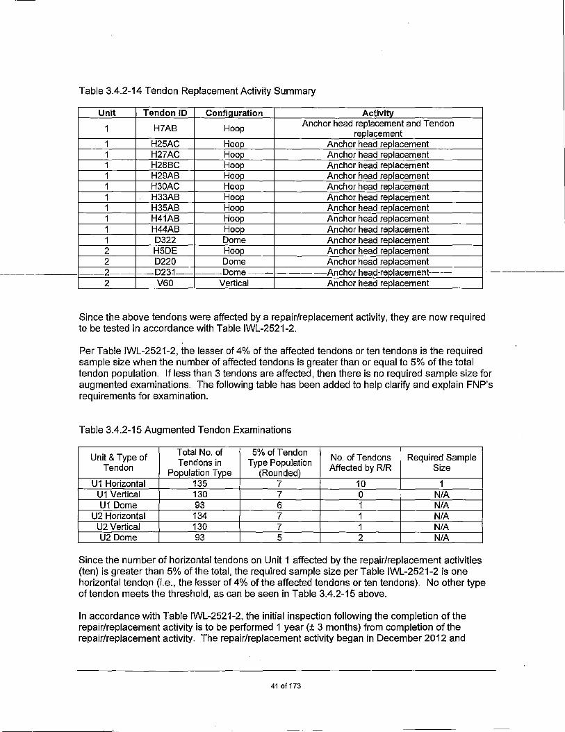
Table 3.4.2-14 Tendon Replacement Activity Summary
Unit Tendon ID Confiauration Activitv
1 H?AB Hoop Anchor head replacement and Tendon replacement
1 H25AC Hoop Anchor head replacement 1 H27AC Hoop Anchor head replacement 1 H28BC Hoop Anchor head replacement 1 H29AB Hoop Anchor head replacement 1 H30AC Hoop Anchor head replacement 1 H33AB Hoop Anchor head replacement 1 H35AB Hoop Anchor head replacement 1 H41AB Hoop Anchor head replacement 1 H44AB Hoop Anchor head replacement 1 D322 Dome Anchor head replacement 2 H5DE Hoop Anchor head replacement 2 D220 Dome Anchor head replacement
----2-- ---D23:1--- -----Dome --------- ---Ancher-head-replaeement-- ---- -----2 V60 Vertical Anchor head replacement
Since the above tendons were affected by a repair/replacement activity, they are now required to be tested in accordance with Table IWL-2521-2.
Per Table IWL-2521-2, the lesser of 4% of the affected tendons or ten tendons is the required sample size when the number of affected tendons is greater than or equal to 5% of the total tendon population. If fess than 3 tendons are affected, then there is no required sample size for augmented examinations. The following table has been added to hef p clarify and explain FNP's requirements for examination.
Table 3.4.2-15 Augmented Tendon Examinations
Unit & Type of Total No. of 5% of Tendon No. of Tendons Required Sample Tendons in Type Population Tendon Population Tvpe (Rounded) Affected by R/R Size
U1 Horizontal 135 7 10 1 U1 Vertical 130 7 0 N/A U1 Dome 93 6 1 N/A
U2 Horizontal 134 7 1 N/A U2 Vertical 130 7 1 N/A U2 Dome 93 5 2 N/A
Since the number of horizontal tendons on Unit 1 affected by the repair/replacement activities (ten) is greater than 5% of the total, the required sample size per Table IWL-2521-2 is one horizontal tendon (i.e., the lesser of 4% of the affected tendons or ten tendons). No other type of tendon meets the threshold, as can be seen in Table 3.4.2-15 above.
In accordance with Table IWL-2521-2, the initial inspection following the completion of the repair/replacement activity is to be performed 1 year (± 3 months) from completion of the repair/replacement activity. The repair/replacement activity began in December 2012 and
41 of 173

concluded in September 2013. Since only 1 of the affected tendons actually requires examination in the following year, FNP requested an alternative to delay examination of the 1 tendon. This alternative was submitted to the NRC under FNP-ISl-ALT-14, "Joseph M. Farley Nuclear Plant Unit 1, Proposed Alternative for the Fourth Interval lnservice Inspection (FNP-ISlAL T-14, Version 1.0," (ML 14050A382) (Reference 30). SNC requested that the examination of the Unit 1 tendons, be deferred to the next regularly scheduled examination, which is currently planned for 2016. After some additional questions from the NRC, the alternative was approved as documented in the NRC SER, "Joseph M. Farley, Unit 1 Alternative Request Regarding Containment Building Tendon Examination Schedule (TAC No. MF3488)," dated July 11, 2014 (ML 14169A195) (Reference 31).
During the Forty-Year Tendon Surveillance, currently scheduled to occur during 2016, one of ten horizontal Unit 1 tendons affected by the repair/replacement activity will need to be examined along with the normal scope of tendon examinations. As in accordance with Table IWL-2521-2, once the initial inspection following the repair/replacement activity has occurred, examination of the tendons affected by the repair/replacement activity will be examined in a schedule to coincide with the remaining population.
3.4.3 Supplemental Inspection Requirements
With the implementation of the proposed change, TS 5.5.17 will be revised by replacing the reference to RG 1.163 (Reference 1) with reference to NEI 94-01, Revision 3-A (Reference 2). This will require that a general visual examination of accessible interior and exterior surfaces of the containment for structural deterioration that may affect the containment leak-tight integrity be conducted. This inspection must be conducted prior to each Type A test and during at least three other outages before the next Type A test if the interval for the Type A test has been extended to 15 years in accordance with the following sections of NEI 94-01, Revision 3-A:
• Section 9.2.1, "Pretest Inspection and Test Methodology" • Section 9.2.3.2, "Supplemental Inspection Requirements"
In addition to the IWE examinations scheduled in accordance with the Containment lnservice Inspection Program, the performance of inspections per the Containment Leakage Rate Testing Program, will be utilized to ensure compliance with the visual inspection requirements of TS SR 3.6.1.1, SR 3.6.1.2 and NEI 94-01, Revision 3-A.
3.4.4 Results of Recent Containment Examinations
Results of Recent IWE Examinations
1 R25 Refueling Outage
1 R25 examinations were performed under the direct supervision of responsible IWE engineering personnel. Most of the areas had been observed, noted and evaluated in previous general and VT-3 examinations.
The following were the reported conditions and engineering recommendations:
Indication 1 noted approximately 29 inches of intermittent scratches with some gouges 1/2 in. to 314 in. long x 1/8 in. wide. The gouges were all 1/16 in. deep or less, located near 195 degrees at 159 ft elevation. Engineering analysis of the degraded liner plate showed a
42of173

minimum thickness of 1/32 in. is acceptable as long as it serves the function of a leak tight barrier. Therefore, the conditions identified were determined to not have any adverse affect on the performance of the liner membrane. The indications were recoated during the 1 R26 refueling outage.
Indication 2 noted tack welds on liner plate to support test bars, located near 270 degrees at 160 ft elevation. There is no rust on the tack welds. The exposed welds were recoated during 1R26.
Indication 3 noted approximately 30 inches of intermittent scratches with some gouges 1/2 in. to 3/4 in. long x 1/8 in. wide. The gouges were all 1/32 in. deep or less, located near 195 degrees at 159 ft elevation. Engineering analysis of the degraded liner plate showed a minimum thickness of 1/32 in. is acceptable as long as it serves the function of a leak tight barrier. Therefore, the conditions identified were determined to not have any adverse affect on the performance of the liner membrane. The indications were recoated during the 1 R26 refueling outage .
. __ Indication 8_noted_miscellaneous-scratches,-with .. bare metal exposed. There.was-no rust- on-the- - - - -- ··-------~ scratches. The scratches were approximately 12 in. long and 3/8 in. wide, with no measurable depth. This indication is located on the east side of containment, 4 ft. to the left of the polar crane ladder and 12 ft below the polar crane. The identified areas were recoated during 1 R26.
Indication 11 noted scratches on the liner approximately 30 in. long by 3/4 in. wide, exposing the bare metal liner. The scratches are located at 38 degrees and 146 ft elevation. There was no rust. The identified areas were recoated during 1 R26.
Indication 12 noted a scratch 8 in. long by 1 in. wide, exposing bare metal. There is no rust. The scratch is located at 35 degrees and 130 ft elevation. The identified areas were recoated during 1 R26.
Indication 13 noted a small gouge approximately 2 in. long and 1/32 in. deep. The gouge is located near 140 degrees at elevation 106 ft. Engineering analysis of the degraded liner plate showed a minimum thickness of 1/32 in. is acceptable as long as it serves the function of a leak tight barrier. Therefore, the conditions identified were determined to not have any adverse affect on the performance of the liner membrane. The indications were recoated during the 1 R26 refueling outage.
Indication 14 noted moisture barrier functional, but degraded at the intersection of the floor and the liner plate, near leak chase port #55 on the 105 ft elevation. There is no evidence of moisture penetration. A new section of moisture barrier was installed at Indication 14 during 1R26.
Indication 15 noted a 3 ft section of moisture barrier that is functional, but degraded, located at 163 degrees, elevation 105 ft. There is no evidence of moisture penetration. A new section of moisture barrier was installed at Indication 15 during 1 R26.
Indication 16 noted an area of moisture barrier that is functional, but degraded, located at between 250 degrees to 272 degrees. There is no evidence of moisture penetration. A new section of moisture barrier was installed at Indication 16 during 1 R26.
43of173
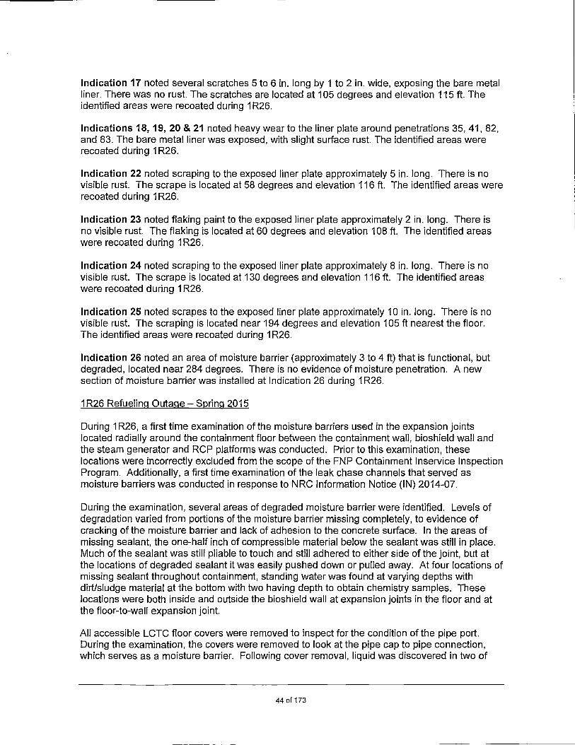
Indication 17 noted several scratches 5 to 6 in. long by 1 to 2 in. wide, exposing the bare metal liner. There was no rust. The scratches are located at 105 degrees and elevation 115 ft. The identified areas were recoated during 1 R26.
Indications 18, 19, 20 & 21 noted heavy wear to the liner plate around penetrations 35, 41, 82, and 83. The bare metal liner was exposed, with slight surface rust. The identified areas were recoated during 1 R26.
Indication 22 noted scraping to the exposed liner plate approximately 5 in. long. There is no visible rust. The scrape is located at 58 degrees and elevation 116 ft. The identified areas were recoated during 1 R26.
Indication 23 noted flaking paint to the exposed liner plate approximately 2 in. long. There is no visible rust. The flaking is located at 60 degrees and elevation 108 ft. The identified areas were recoated during 1 R26.
Indication 24 noted scraping to the exposed liner plate approximately 8 in. long. There is no visible rust. The scrape is located at 130 degrees and elevation 116 ft. The identified areas were recoated during 1 R26.
Indication 25 noted scrapes to the exposed liner plate approximately 10 in. long. There is no visible rust. The scraping is located near 194 degrees and elevation 105 ft nearest the floor. The identified areas were recoated during 1 R26.
Indication 26 noted an area of moisture barrier (approximately 3 to 4 ft) that is functional, but degraded, located near 284 degrees. There is no evidence of moisture penetration. A new section of moisture barrier was installed at Indication 26 during 1 R26.
1 R26 Refueling Outage- Spring 2015
During 1 R26, a first time examination of the moisture barriers used in the expansion joints located radially around the containment floor between the containment wall, bioshield wall and the steam generator and RCP platforms was conducted. Prior to this examination, these locations were incorrectly excluded from the scope of the FNP Containment lnservice Inspection Program. Additionally, a first time examination of the leak chase channels that served as moisture barriers was conducted in response to NRC Information Notice (IN) 2014-07.
During the examination, several areas of degraded moisture barrier were identified. Levels of degradation varied from portions of the moisture barrier missing completely, to evidence of cracking of the moisture barrier and lack of adhesion to the concrete surface. In the areas of missing sealant, the one-half inch of compressible material below the sealant was still in place. Much of the sealant was still pliable to touch and still adhered to either side of the joint, but at the locations of degraded sealant it was easily pushed down or pulled away. At four locations of missing sealant throughout containment, standing water was found at varying depths with dirt/sludge material at the bottom with two having depth to obtain chemistry samples. These locations were both inside and outside the bioshield wall at expansion joints in the floor and at the floor-to-wall expansion joint.
All accessible LCTC floor covers were removed to inspect for the condition of the pipe port. During the examination, the covers were removed to look at the pipe cap to pipe connection, which serves as a moisture barrier. Following cover removal, liquid was discovered in two of
44of173

the recessed portions of the LCTCs (Nos. 4 and 23). Two LCTCs' pipes and pipe caps were completely corroded through (Nos. 10 and 52). The conditions observed prompted pipe cap removal on forty-seven additional locations, of which thirty-one locations were noted to have varying levels of moisture in the pipe.
UT measurements were performed on the inaccessible portion of the containment liner plate. One UT location was on a portion of the liner plate located in one of the wetted expansion joints, the other two locations were underneath leak chase channels at LCTC Nos. 6 and 45. All three examinations were performed with results that were repeatable and acceptable. Nominal liner plate thickness at these locations is 1/4-inch. The three locations examined had thickness measurements of 0.25 inches, 0.30-0.32 inches, and 0.35 inches, respectively.
In addition to the ultrasonic (UT) examinations, numerous visual inspections were performed. All locations with missing expansion joint sealing were visually inspected for evidence of liquid and to inspect the bottom of the expansion joints. However, the inability to completely remove the liquid, grit and silt in the joint resulted in the inability to perform a qualified or unqualified visual examination of the liner.
2R23 IWE Examination Results
Liner Examination
All accessible surfaces in all four containment liner quadrants were examined during 2R23. The following conditions were noted:
The liner at elevation 105 ft was examined from the south wall of the fuel transfer canal around to the north wall of the fuel transfer canal. Three areas of interest were noted. Disposition of the areas showed the results of the examination to be acceptable.
The liner at elevation 129 ft was examined from the south wall of the fuel transfer canal around to the north wall of the fuel transfer canal. Two areas of interest were noted. Disposition of the areas showed the results of the examination to be acceptable.
Three areas were observed where the paint was flaking and/or cracking. Additionally, one area was observed approximately 9 ft to the right of the equipment hatch. The area was 8 to 1 O ft above the 155 ft elevation and had scraped paint. The area of interest was approximately 18 inches square. No rust or pitting was observed.
A piece of metal, which appeared to be previously welded to the liner plate, was dil?covered at the 333 azimuth location just behind the polar crane platform rail and above the operator's platform. This was identified in the initial IWE inspection. Engineering indicated that this is a known defect with no concern for degradation of the liner integrity.
Moisture Barrier Examination
During 2R23, several areas of degraded moisture barrier were identified. Levels of degradation varied from portions of the moisture barrier missing completely, cracking of the moisture barrier and a lack of adhesion to the concrete surface. Much of the sealant was still pliable to the touch and still adhered to either side of the joint. However, at locations where the sealant was degraded, the sealant was easily pushed down or pulled away. At twelve locations of missing sealant throughout containment, standing water was found at varying depths with dirt/sludge
45of173
material at the bottom. These locations were both inside and outside the bioshield wall at expansion joints in the floor and at the floor to wall expansion joint (not including the periphery of containment).
As a result of the identified degradation of the moisture barrier, the provisions of ASME Section XI, Subsection IWE were invoked to assess the condition of the inaccessible portion of the liner plate to ensure containment integrity had been maintained. UT thickness examinations at three locations on the containment liner plate showed no evidence of loss of material. An engineering evaluation was completed prior to the conclusion of the 2R23 RFO that evaluated the UT thickness data and determined the containment liner's leak-tight integrity was still intact and acceptable for at least one more operating cycle.
In addition to the moisture barrier examinations, all LCTC floor covers were removed to inspect the condition of the port. During the examination of the LCTCs, the covers for the LCTCs were removed to look at the pipe cap to pipe connection (moisture barrier). Liquid was discovered in two of the recessed portions of the LCTC. One LCTC did not have a pipe cap installed and another LCTC's pipe and pipe cap were completely corroded through. The conditions were
_______ assessed-after all initiaL examinations were-performed. -Eurther: investigation-into-the LCTC--- - ---- - - - --- ----resulted in the removal of the pipe cap on 51 locations of which 20 locations were noted to have varying levels of moisture in them. The remaining locations were noted as being dry. In addition, when the pipe cap on LCTC 50 was removed, liquid was observed flowing out of the pipe for a short time. A video probe was utilized to look inside the LCTCs that had their pipe caps removed.
2R24 IWE Examination Results
During 2R24, an examination was performed on the containment moisture barrier along with the reactor pressure vessel sump liner. The examination found various areas of staining throughout the examination area. Two areas of flaking coatings were observed which were previously identified during the 2R21 RFO and have not changed. Various areas of minor blistered and chipped coatings were observed. No corrosion or degradation was observed on uncoated areas of liner plate. One unidentified leak chase port was observed.
Results of Recent IWL Examinations
Unit 1 35th Year I Unit 2 30th Year Examination - Containment Structure Post Tensioning System
The 2012 tendon surveillance at Farley Nuclear Plant began on April 30, 2012 and was completed on June 7, 2012. This examination satisfied the requirements for the Unit 1 35th Year and Unit 2 301h Year examinations of the Containment Structure Post Tensioning System. The tendon surveillance program consists of a periodic inspection of the condition of a selected group of tendons. This surveillance period consisted of a visual inspection of the post tensioning system. A visual tendon surveillance consists of: sheathing filler inspection and testing,-inspection for water, anchorage inspection, concrete inspection around tendons, and replacement of grease after completion of all inspections. Ten (10) tendons on Unit 1 and nine (9) tendons on Unit 2 were selected for inspection during the tendon surveillance. These tendons are termed "Original Scope Tendons."
The results of the examinations were as follows:
46of173

IWL-3221 Acceptance by Examination
IWL-3221.3 Tendon Anchorage Areas: The condition of tendon anchorage areas is acceptable if:
(a) there is no evidence of cracking in anchor heads, shims or bearing plates
Results: Detailed inspections did not reveal any cracks in the anchorage components for any inspected tendon end.
(b) there is no evidence of active corrosion;
Results: The field end of Unit 1 hoop tendon H35AB revealed corrosion Level C. This was reported in NCR FN1078-002. No other tendon end inspected revealed active corrosion on the anchorage components.
(c) broken on unseated wires; broken strands, and detached buttonheads were documented and accepted during a pre-seNice examination or during a previous inseNice examination;
Results: During the examination of surveillance tendon ends, missing or protruding wires/buttonheads were discovered on three (3) tendons on Unit 1 and three (3) tendons on Unit 2 that were not previously reported.
(d) cracks in the concrete adjacent to the bearing plates do not exceed 0.01 in (3mm) in width;
Results: No cracks exceeding 0.010 in. were detected in the 24 in. of concrete adjacent to the bearing plates of the tendon ends inspected.
(e) there is no evidence of free water
Results: No water was observed during the cap removal of any inspected tendon.
IWL-3222 Acceptance by Evaluation. Items with examination results that do not meet the acceptance standards of IWL-3221 shall be evaluated as required by IWL-3300.
Results: All conditions that did not meet the corresponding inspection criteria were documented, evaluated and deemed acceptable via Farley Plant Action Report process.
--,
Based upon the evaluation of the ISi results for the 2012 Farley Nuclear Plant Containment Building Tendon Surveillance report, the containment structures have experienced no abnormal degradation of their post-tensioning system.
2012 Containment Concrete General Visual Examination
During the 2012 containment structure post tensioning systems tendon surveillance, the general visual examination of the FNP-1 and FNP-2 concrete surfaces was performed in accordance with ASME Section XI, Subsection IWL. The results are as follows:
47of173

Unit 1 Tendon Gallery
Information Only Indications: Water leakage into tunnel at tunnel wall exterior below containment basemat; oil seeping around grease caps and inlet plugs.
Reportable Indications: Surface rusting of grease cap bolts
Disposition by Responsible Engineer: Conditions are acceptable. Similar conditions recorded during 2006 IWL Inspection.
Unit 1 Containment Dome
Reportable Indications: Concrete spalling greater than 8 in.; passive cracks greater than 0.030 in.; rail embeds rusting and staining concrete, form tie grout patches
Disposition by Responsible Engineer: Conditions are acceptable. Similar conditions recorded during 2006 IWL Inspection.
Unit 1 Buttress A Face
Information Only Indications: Small cracks greater than 0.010 in.; small bug holes
Reportable Indications: Small spalls greater than 6 in.; form tie grout patches
Disposition by Responsible Engineer: Conditions are acceptable. Similar conditions recorded during 2006 IWL Inspection.
Unit 1 Buttress B Face
Information Only Indications: Small cracks greater than 0.010 in.; small bug holes
Reportable Indications: Small spalls greater than 6 in.; form tie grout patches; spall on edge of buttress with dimensions 18 by 18 by 2 in. deep, grout patch observed to be loose
Disposition by Responsible Engineer: Conditions are acceptable. Similar conditions recorded during 2006 IWL Inspection. Grout patch is scheduled to be repaired by December 2017.
Unit 1 Buttress C Face
Information Only Indications: Small cracks greater than 0.010 in.; small bug holes; small spalls; form tie grout patches
Disposition by Responsible Engineer: Conditions are acceptable. Similar conditions recorded during 2006 IWL Inspection.
Unit 1 Between Buttress A and Buttress B
Information Only Indications: Small bug holes; form tie grout patches; cracks greater than 0.010 in.
Reportable Indications: Grease leak out of crack in construction pour line greater than 0.01 O in.
48of173

Disposition by Responsible Engineer: Conditions are acceptable. Similar conditions recorded during 2006 IWL Inspection.
Unit 1 Between Buttress B and Buttress C
Information Only Indications: Small bug holes; form tie grout patches; cracks greater than 0.010 in.
Reportable Indications: Grease leak out of crack in construction pour line greater than 0.01 O in., 4 ft from buttress B between tendons H17BC and H16BC, grease leak was active though minimal; grease leak out of crack in construction pour line greater than 0.010 in., 2 ft from buttress C by tendon H43CB, appears to be inactive; grease leak out of grease inlet plug in concrete above bearing plate of H27BC at buttress B, old grease running down buttress to bottom, inactive leak; grease leak out of grease cap inlet plug (old, inactive) on tendon H44CB at buttress C and running down to H41 CB at buttress C
_________ Disp_osition_by_Responsible-Enginee~:-Conditions-are-acceptable.-Similar-conditions-reeorded---· -------during 2006 IWL Inspection.
Unit 1 Between Buttress C and Buttress A
Information Only Indications: Small bug holes; form tie grout patches; cracks greater than 0.010 in.
Reportable Indications: Grease leaking out of crack in construction pour line greater than 0.010 in. 25 ft from buttress A and 25 ft up from roof, old grease, inactive; grease leak out of crack in construction pour line greater than 0.01 O in. 35 ft. from buttress A and 35 ft up from roof, old grease, inactive; grease leak out of crack in construction pour line greater than 0.010 in., 20 ft from buttress C and 25 ft up from roof, old grease, inactive
Disposition by Responsible Engineer: Conditions are acceptable. Similar conditions recorded during 2006 IWL Inspection.
Unit 1 Ring Girder - Buttress B to Buttress C
Information Only Indications: Small bug holes; form tie grout patches;
Reportable Indications: Passive cracks greater than 0.030 in.; efflorescence from rail anchor pads; small spalls around dome tendon pocket edges greater than 6 in.
Disposition by Responsible Engineer: Conditions are acceptable. Similar conditions recorded during 2006 IWL Inspection.
Unit 1 Ring Girder - Buttress A to Buttress B
Information Only Indications: Small bug holes; form tie grout patches
Reportable Indications: Passive cracks greater than 0.030 in.; efflorescence from rail tie anchor pads; small spalls around dome tendon pocket edges greater than 6 in.
49of173

Disposition by Responsible Engineer: Conditions are acceptable. Similar conditions recorded during 2006 IWL Inspection.
Unit 1 Ring Girder - Buttress C to Buttress A
Information Only Indications: Small bug holes; form tie grout patches;
Reportable Indications: Passive cracks greater than 0.030 in.; efflorescence from rail tie anchor pads; small spalls greater than 6 in. around dome tie tendon pocket edges
Disposition by Responsible Engineer: Conditions are acceptable. Similar conditions recorded during 2006 IWL Inspection.
Unit 1 Room 184 - 100 ft Elevation
Reportable Indications: Grease leaking out of inlet plug in concrete above HSBC C Buttress running down to bottom of buttress
Disposition by Responsible Engineer: Plug scheduled to be tightened by December 2017.
Unit 1 Room 332 - 139 ft Elevation
Reportable Indications: Grease leaking out of inlet plug on K22AB A Buttress running down to bottom of buttress
Disposition by Respo·nsible Engineer: Plug scheduled to be tightened by December 2017.
Unit 2 Tendon Gallery
Information Only Indications: Water leaking into tunnel at tunnel interior wall below basemat
Reportable Indications: Oil seepage around grease inlet plugs; grease cap bolts show surface rust
Disposition by Responsible Engineer: Conditions are acceptable. Similar conditions recorded in prior IWL inspection (2006).
Unit 2 Dome
Reportable Indications: Small spalls greater than 6 in.; passive cracks greater than 0.030 in.; form tie grout patches; rail embeds rusting and staining concrete
Disposition by Responsible Engineer: Conditions are acceptable. Similar conditions recorded in prior IWL inspection (2006). Dome coating and rail system scheduled to be repaired by December 2017.
Unit 2 Buttress D Face
Information Only Indications: Small cracks greater than 0.010 in.; small bug holes
Reportable Indications: Small spalls; form tie grout patches
50 of173

Disposition by Responsible Engineer: Conditions are acceptable. Similar conditions recorded in prior IWL inspection (2006).
Unit 2 Buttress E Face
Information Only Indications: Small cracks greater than 0.010 in.; small bug holes
Reportable Indications: Small spalls greater than 6 in.; form tie grout patches
Disposition by Responsible Engineer: Conditions are acceptable. Similar conditions recorded in prior IWL inspection (2006).
Unit 2 Buttress F
Information Only Indications: Small cracks greater than 0.010 in.; small bug holes
-- -------- ------Repertable-lmficatiens: Smallspalls-greater than-6-in.-;-form-tiegrout-patches-- -
Disposition by Responsible Engineer: Conditions are acceptable. Similar conditions recorded in prior IWL inspection (2006).
Unit 2 Between Buttress D and E
Information Only Indications: Small bug holes; small cracks greater than 0.010 in.
Reportable Indications: Form tie grout patches; grease leak out of crack greater than 0.010 in. in construction pour line, active through minimal above top left corner of equipment hatch
Disposition by Responsible Engineer: Conditions are acceptable. Similar conditions recorded in prior IWL inspection (2006).
Unit 2 Between Buttress E and Buttress F
Information Only Indications: Small bug holes; small cracks greater than 0.010 in.
Reportable Indications: Form tie grout patches
Disposition by Responsible Engineer: Conditions are acceptable. Similar conditions recorded in prior IWL inspection (2006).
Unit 2 Between Buttress F and Buttress D
Information Only Indications: Small bug holes; small cracks greater than 0.01 O in.
Reportable Indications: Form tie grout patches
Disposition by Responsible Engineer: Conditions are acceptable. Similar conditions recorded in prior IWL inspection (2006).
Unit 2 Ring Girder - Buttress D to Buttress E
51 of 173

Information Only Indications: Small bug holes; form tie grout patches
Reportable Indications: Passive cracks greater than 0.030 in.; efflorescence from rail anchor pads; small spalls greater than 6 in. around dome tendon pocket edges
Disposition by Responsible Engineer: Conditions are acceptable. Similar to conditions recorded in prior IWL inspection (2006).
Unit 2 Ring Girder - Buttress E to Buttress F
Information Only Indications: Small bug holes; form tie grout patches
Reportable Indications: Passive cracks greater than 0.030 in.; efflorescence from rail anchor pads; small spalls greater than 6 in. around dome tendon pocket edges
Disposition by Responsible Engineer: Conditions are acceptable. Similar to conditions ----- recorded in-prior IWb-inspection (2006)~-- -- --- ---- ----------- - --- ----- - ------- - __ ---------- __ _
Unit 2 Ring Girder - Buttress F to Buttress D
Information Only Indications: Small bug holes; form tie grout patches
Reportable Indications: Passive cracks greater than 0.030 in.; efflorescence from rail anchor pads; small spalls greater than 6 in. around dome tendon pocket edges
Disposition by Responsible Engineer: Conditions are acceptable. Similar conditions recorded in prior IWL inspection (2006).
Unit 2 Room 2429 - Elevation 155 ft
Surface of concrete painted - no indications noted
Reportable Indications: Grease leaking out of H21 EF inlet grease plug in concrete. Grease running down buttress to H17EF.
Disposition by Responsible Engineer: Conditions are acceptable. Similar conditions recorded in prior IWL inspection (2006).
Unit 2 Room 2184 - Elevation 100 ft
Reportable Indication: Grease leaking through concrete crack greater than 0.01 O in. in line with M1 FE, 1 ft from buttress (active leak)
Disposition by Responsible Engineer: Conditions are acceptable. Similar to conditions recorded in prior IWL inspection (2006).
Containment Coating Assessments
1 R25 Containment Coatings Assessment
52of173

The 1 R25 Containment Coatings Assessment was performed between March 30 through April 21, 2015. The following results were documented.
Coating identification and resolution are those that appear in Section 3.4.4, Results of Recent IWE Examinations - 1 R25 Refueling Outage.
2R24 Containment Coatings Assessment
During 2R24, an assessment of the containment coatings was performed. The following results were documented.
Flaking paint found on liner wall of containment at 155 ft elevation, azimuth 236 approximately 12 inches by 18 inches. This location was recoated during 2R24 with Amercoat 90N coating.
3.4.5 Containment Leakage Rate Testing Program - Type B and Type C Testing Program
---- -- --- - --- -- ---------- --- --- -- ---- ------ -- -- ----- -- ----- ----- -- -------- ---------------- -- ----------
FNP Types B and C testing program requires testing of electrical penetrations, airlocks, hatches, flanges and CIVs in accordance with 10 CFR 50, Appendix J, Option B and RG 1.163 (Reference 1). The results of the test program are used to demonstrate that proper maintenance and repairs are made on these components throughout their service life. The Types B and C testing program provides a means to protect the health and safety of plant personnel and the public by maintaining leakage from these components below appropriate limits. In accordance with TS 5.5.17, the allowable maximum pathway total Types Band C leakage is 0.6 La (140,862 standard cubic centimeters per minute (seem)) where La equals approximately 234,771 seem.
As discussed in NUREG-1493 (Reference 8), Type Band Type C tests can identify the vast majority of all potential containment leakage paths. Type B and Type C testing will continue to provide a high degree of assurance that containment integrity is maintained.
A review of the As-Found (AF) I As-Left (AL) test values for FNP Unit 1 and Unit 2 can be summarized as:
FNP Unit 1 As-Found minimum pathway leak rate shows an average of 11.33% of 0.6 La with a high of 14.68% of 0.6La.
FNP Unit 1 As-Left maximum pathway leak rate shows an average of 14.31% of 0.6 La with a high of 26.55% of 0.6 La.
• FNP Unit 2 As-Found minimum pathway leak rate shows an average of 13.42% of 0.6 La with a high of 22.31 % of 0.6La.
FNP Unit 2 As-Left maximum pathway leak rate shows an average of 22.12% of 0.6 La with a high of 41.08% of 0.6 La.
Tables 3.4.5-1 and 3.4.5-2 provide local leak rate test (LLRT) data trend summaries for FNP Units 1 and 2 since 2006. This summary demonstrates a history of satisfactory Type B and Type C tested component performance from the Spring of 2006 through the Spring of 2015,
53of173
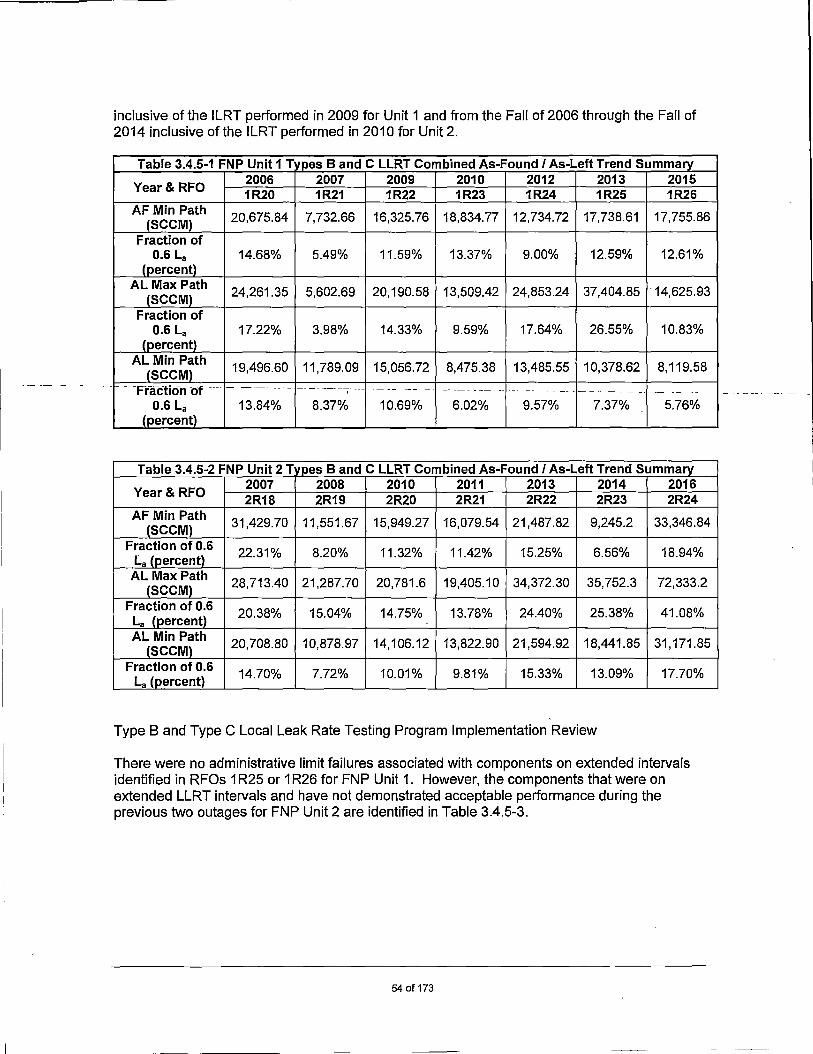
I_
inclusive of the ILRT performed in 2009 for Unit 1 and from the Fall of 2006 through the Fall of 2014 inclusive of the ILRT performed in 2010 for Unit 2.
Table 3.4.5-1 FNP Unit 1 T fpes B and C LLRT Combined As-Found I As-Left Trend Summarv
Year& RFO 2006 2007 2009 2010 2012 2013 2015 1R20 1R21 1R22 1R23 1R24 1R25 1R26
AF Min Path 20,675.84 7,732.66 16,325.76 18,834.77 12,734.72 17,738.61 17,755.86 (SCCM)
Fraction of 0.6 La 14.68% 5.49% 11.59% 13.37% 9.00% 12.59% 12.61%
(percent) AL Max Path
24,261.35 5,602.69 20,190.58 13,509.42 24,853.24 37,404.85 · 14,625.93 (SCCM)
Fraction of 0.6 La 17.22% 3.98% 14.33% 9.59% 17.64% 26.55% 10.83%
(percent) AL Min Path
19,496.60 11,789.09 15,056.72 8,475.38 13,485.55 10,378.62 8, 119.58 (SCCM)
- - ·Fractio-n ·or --- - --------· -- -- --- --- --- ---- --- -- ------- - -- - - -- - --- -- --- - - -- ---- -- --- --
0.6 La 13.84% 8.37% 10.69% 6.02% 9.57% 7.37% 5.76% (percent)
Table 3.4.5-2 FNP Unit 2 Tvpes Band C LLRT Combined As-Found I As-Left Trend Summary
Year & RFO 2007 2008 2010 2011. 2013 2014 2016 2R18 2R19 2R20 2R21 2R22 2R23 2R24
AF Min Path 31,429.70 11,551.67 15,949.27 16,079.54 21,487.82 9,245.2 33,346.84
(SCCM) Fraction of 0.6
22.31% 8.20% 11.32% 11.42% 15.25% 6.56% 18.94% La (percent) AL Max Path
28,713.40 21,287.70 20,781.6 19,405.10 34,372.30 35,752.3 72,333.2 (SCCM)
Fraction of 0.6 20.38% 15.04% 14.75% 13.78% 24.40% 25.38% 41.08%
La (percent) AL Min Path
20,708.80 10,878.97 14,106.12 13,822.90 21,594.92 18,441.85 31, 171.85 (SCCM)
Fraction of 0.6 14.70% 7.72% 10.01% 9.81% 15.33% 13.09% 17.70%
La (percent)
Type Band Type C Local Leak Rate Testing Program Implementation Review
There were no administrative limit failures associated with components on extended intervals identified in RFOs 1 R25 or 1 R26 for FNP Unit 1. However, the components that were on extended LLRT intervals and have not demonstrated acceptable performance during the previous two outages for FNP Unit 2 are identified in Table 3.4.5-3.
54of173

-- ----------
Table 3 lamentation Review 2R23 - Fall 2014
Component As-Found SCCM
Admin Limit SCCM
As-Left SCCM
Cause of Failure
Corrective Action
Scheduled Interval
Q2G21HV337 870 800 870 Note 1 Note 1 30 Months 2R24 - S rin 2016
Component As-Found SCCM
Admin Limit As-Left SCCM SCCM
Cause of Failure
Corrective Action
Scheduled Interval
Q2P16V081 1695 1410 1695 Note 2 Note 2 30 Months
Note 1:
Note 2:
This co total con
mponent was accepted for continued service without rework or repair. The tribution of the As-Left Penetration 78 maximum pathway leakage is 4.26% of
Overall, there was approximately a 75% margin between the As-Left maximum totals and 0.6 La during 2R23. Q2G21 HV337 is scheduled for replacement
0.6 La. pathway during th e 2R25 RFO.
This co mponent was accepted for continued service without rework or repair. ··-· -- ---~ -- Q2P.16\/ Offns the inl5oarcrc1v fo(FNP-ZPer1etration-J2.--Measurecr1eakage ·an tne- - · --- - ---- ·
outboard CIVs 2QP16V072 and 2QP16V203 had observed leakage at 516 seem. A maxi mu m pathway leakage rate of 516 seem was assigned to the penetration. Q2P16V 081 is scheduled for repair during the 2R25 RFO.
Statistics on Nu mber of Components on Extended Intervals
Unit 1:
The percentage o f the total number of FNP-1 Appendix J Type B tested components that are on ed performance-based test intervals is approximately 83%. 120-month extend
The percentage o f the total number of FNP-1 Appendix J Type C tested components that are on d performance-based test intervals is approximately 83%. 60-month extende
Unit 2:
The percentage o f the total number of FNP-2 Appendix J Type B tested components that are on ed performance-based test intervals is approximately 88%. 120-month extend
The percentage o f the total number of FNP-2 Appendix J Type C tested components that are on d performance-based test intervals is approximately 90%. 60-month extende
3.5 Operating Experience
During the conduc t of the various examinations and tests conducted in support of the containment relat or that provide ind
ed programs previously mentioned, issues that do not meet established criteria ication of degradation, are identified, placed into the site's corrective action ective actions are planned and performed. program, and corr
For the FNP Prim ary Containment, the following site specific and related industry events have r impact on the FNP Primary containment: been evaluated fo
55of173

• IN 89-79, "Degraded Coatings and Corrosion of Steel Containment Liners"
• IN 92-20, "Inadequate Local Leak Rate Testing"
• IN 96-13, "Potential Containment Leak Paths Through Hydrogen Analyzers"
• IN 99-10, "Degradation of Pre-stressing Tendon Systems in Pre-stressed Concrete Containments"
• IN 2004-09, "Corrosion of Steel Containment and Containment Liner"
• IN 2010-12, "Containment Liner Corrosion"
• IN 2014-07, "Degradation of Leak-Chase Channel Systems for Floor Welds of Metal Containment Shell and Concrete Containment Metallic Liner"
__ _ ___ __ __ _ __ • ____ R~gµl~1ory_lss_!!_~ ~-l:!lllOJ?ry_(~I§) 2016-07, "Containment Shell or Liner Moisture Barrier Inspection" - -- -- ----- ---- -- - -- - -- ------ ------ --- ---- - - ---
• Operating Experience Report (OER) OE32389, "Containment Liner Through-Wall Degradation at Turkey Point-3 in.
• OER OE31696, "Concrete Containment Delamination Exposed during Steam Generator Replacement (SGR) Hydro-Excavation at Crystal River 3 in.
Each of these areas is discussed in detail in Sections 3.5.1 through 3.5.10, respectively.
3.5.1 IN 89-79, "Degraded Coatings and Corrosion of Steel Containment Liners"
NRC IN 89-79 and Supplement 1 address coating damage and corrosion of the steel ice condenser containment vessels at two BWR facilities. Ice condenser-type containment vessels consist of a freestanding steel shell surrounded by a concrete shield building. Between the steel shell and the concrete shell there is an annular air space. Coating damage and corrosion occurred on the outer surface of the steel shell and was caused by boric acid and collected condensation on the floor of the annular space between the steel shell and the surrounding concrete shield building. Coating damage and corrosion also occurred on the inside surface at the floor level in a 2-inch floor gap filled with cork that interfaces with the coated steel containment. The cork contains moisture originating from the ice condenser or from condensation.
Discussion
FNP has a post-tensioned concrete containment structure. The FNP containment structures do not have an annulus such as described in this IN. Even though _the FNP containment structures have an interior steel liner, there is no space between the liner and the concrete. The accessible portions of this linear are visually inspected every 40 months in conjunction with the containment integrated leak rate test and no corrosion problems have been found. Therefore, no further action is required with regard to this notice.
56of173

3.5.2 IN 92-20, "Inadequate Local Leak Rate Testing"
The NRC issued IN 92-20 to alert licensees of problems with local leak rate testing of two-ply stainless steel bellows used on piping penetrations at four different plants: Quad Cities, Dresden Nuclear Station, Perry Nuclear Plant, and the Clinton Station. Specifically, LLRTs could not be relied upon to accurately measure the leakage rate that would occur under accident conditions, since, during testing, the two plies in the bellows were in contact with each other, restricting the flow of the test medium to the crack locations. Any two-ply bellows of similar construction may be susceptible to the problem. The common issue in the four events was the failure to adequately perform local leak rate testing on different penetration configurations leading to problems that were discovered during ILRT tests in the first three cases.
In the event at Quad Cities, the two-ply bellows design was not properly subjected to LLRT pressure and the conclusion of the utility was that the two-ply bellows design could not be Type B LLRT tested as configured.
---In-the-events at-both-Dresden-andf2erry, flanges-were not considered a leakage-path when-the--- -Type C LLRT test was designed. This omission led to a leakage path that was not discovered until the plant performed an ILRT test.
In the event at Clinton, relief valve discharge lines that were assumed to terminate below the suppression pool minimum drawdown level were discovered to terminate at a level above that datum. These lines needed to be reconfigured and the valves should have been Type C LLRT tested.
Discussion
The event at Quad Cities Station, Unit 1 involved LLRT testing of two-ply steel expansion bellows used on piping penetrations. It was discovered by the licensee that it is not possible to perform a valid Type B LLRT on this type of bellows assembly. The single ply steel bellows assembly used at FNP is not similar in design or construction and is tested in accordance with 1 O CFR 50, Appendix J.
The Dresden Nuclear Power Station, Unit 2 event involved LLRT testing of the Containment Purge valve flanges. It was found that the LLRT procedure did not challenge all possible leakage paths. The test procedure used at FNP challenges all applicable Containment Purge valve flanges. The mini purge valves on Unit 1 were inspected during the Unit 1 RF11. The mini purge exhaust valve (Q1 P12V204) inside containment was discovered installed in the reverse direction. The mini-purge testing procedures were revised to test the 8-inch mini-purge valves inside containment in the accident direction. The results of the tests were satisfactory and comparable to the quarterly test method. Based on the results, the test method was changed to the reverse methodology for the RFO test, only. The quarterly test will not include reverse testing since the TS Bases state that the quarterly tests are not subject to the requirements of 1 O CFR 50, Appendix J.
The event at Perry Nuclear Plant, Unit 1 involved the improper testing of relief valve flanges. The LLRT procedure tested the relief valve flanges in the reverse direction, which did not challenge the correct flanges. All CIVs included in the LLRT program at FNP are tested in accordance with 10 CFR 50, Appendix J which states, "The pressure shall be applied in the direction as that when the valve would be required to perform its safety related function, unless
57of173

it can be determined that the results from the tests for a pressure applied in a different direction will provide equivalent or more conservative results."
The Clinton Power Station, Unit 1 is a BWR and the event involved equipment not applicable to FNP.
3.5.3 IN 96-13, "Potential Containment Leak Paths Through Hydrogen Analyzers"
IN 96-13 was issued to alert addressees to the potential for containment leak paths through hydrogen analyzers either through a failure to test or a failure to restore the system after testing. Catawba Nuclear Station determined that leakage from an internal component in a hydrogen analyzer panel exceeded the containment bypass leakage limits specified in their TS. Tests showed that the source of the bypass leakage was a defective pump shaft seal on a sample pump located inside the hydrogen analyzer cabinet. Braidwood completed a containment ILRT and left the sensing lines inside the hydrogen monitor disconnected resulting in an unfiltered release path from containment to the auxiliary building in the event of an accident.
--------Giscussion-- --- --- - ---- ---- - - -- -- --- ---- -
FNP's post accident hydrogen analyzer system (PAHA) is similar to the system in use at Catawba in that testing is performed on the containment isolation valves only and not through the hydrogen analyzer itself. There are three significant differences, however, between the Catawba and the FNP hydrogen analyzers, which are as follows:
1. Unlike the Catawba installation, the FNP CIVs do close on a containment isolation signal and therefore isolate the PAHAs should a design basis accident occur.
2. Unlike the Catawba installation, the FNP PAHAs are located in the 139 ft electrical penetration room. This room is part of the penetration room filtration system, which is designed to maintain a negative pressure (in the room) and limit the release of radioisotopes to the environment in the event of a LOCA.
3. Significant leakage from the FNP PAHA would result in local radiation alarms and increasing vent stack radiation readings and/or alarms. Operations at FNP would then have the option to discontinue hydrogen monitoring on the affected unit by closing the CIVs if the source of leakage is PAHA.
The post accident combustible gas sample system (PAHA) CIVs at Plant Farley are pressure tested as part of the LLRT program during each RFO. The PAHA CIVs will close on a containment isolation signal even if the system is sampling the containment atmosphere at the time the isolation signal is received. Therefore, although functional test and calibration activities may be in progress, they will not prevent the primary containment isolation from occurring. As part of the IN response, FNP created a procedure to perform a qualitative assessment of potential radioactive leakage outside containment from the PAHA and Post Accident Containment Vent Piping.
The operability of each post accident combustible gas sample system (PAHA) is verified by a quarterly surveillance program, to satisfy TS. A yearly P.M. is performed on each PAHA. These include a pressure test of the PAHA's entries, exits and internals to completely verify the leak integrity of the tubing and components. In addition, whenever maintenance activities breach any of the PAHA's pressure boundaries, the WO planning sequence requires a pressure test. This effectively leak checks the primary components of the PAHA, which are located outboard of the CIVs and are not leak tested by the LLRT Test Program.
58of173

A review of the systems similar to the post accident combustible gas sampling system (PAHAs) was made and is contained in the discussion. The conclusions are as follows:
• The H2 recombiner and the post LOCA air mixing systems are both located inside containment and therefore no further actions are required.
• The post accident sampling system (PASS) has been discussed. Supplemental (visual) procedures are in existence to perform a quantitative assessment of potentially radioactive leakage during each outage. By procedure, a continuous sample flow is routed through the PASS. This sample flow would quickly expose most forms of leakage. In addition, a procedure is performed every 6 months and includes a pressure verification of the system at 10 psig and a vacuum verification of the system at approximately 25 inches of vacuum.
• The containment atmosphere sample systems (RE-11 / RE-12 & RE-67) have been discussed. A unit specific procedure pressurizes the RE-67 system to approximately 6 psig, performs a visual evaluation of the systems and/or system components while pressurized, and performs a leak rate measurement. This pressure test does not
---include the-RE-11--/-RE-1-2-elements-or-inboard/outboard-pumps;-- -- --- - --- --- - --- ----- -
• The RE-11 I RE-12 portion of the containment atmospheric sample system is not required during accident conditions.
• The post accident containment venting system has been discussed. As part of the IN response, FNP created a procedure to perform a qualitative assessment of potential radioactive leakage outside containment from the PAHA and Post Accident Containment Vent Piping.
The maintenance planning work sequences for 1) the post accident combustible pump sample system (PAHA), 2) the post accident sampling system (PASS) 3) the containment atmospheric sample systems, and 4) the post accident containment venting system specifies certain
1 instructions for reassembly. This maintenance planning work sequence modification specifies that whenever any of these system's pressure boundaries are "breached," a pressure test of the system and adjacent piping/ tubing must be performed. This pressure test will verify the reassembled integrity of the components, fittings, piping/tubing for appropriate portions of the systems which had been breached.
FNP's containment integrated leak rate test is similar to the Braidwood Station, in that, the containment penetration hydrogen sensing lines for one train ~re disconnected at the "sample bomb". Unlike the Braidwood Station, however, the FNP connections are self sealing quick disconnect fittings, and if they were left disconnected (as in the case of Braidwood) there would not be a leakage path. The ILRT procedure provides restoration steps and verification steps to ensure that the "sample bomb" has been replaced/restored to the proper configuration. In addition, FNP administrative procedures provide detailed guidance and controls for releasing work and functionally accepting work to insure all equipment is properly returned to service after testing or maintenance.
3.5.4 IN 99-10, "Degradation of Pre-stressing Tendon Systems in Pre-stressed Concrete Containments"
The NRC issued IN 99-1 Oto alert nuclear power plants to degradation of pre-stressing systems components of pre-stressed concrete containments (PCCs). The specific items addressed are
59of173
(1) pre-stressing tendon wire breakage, (2) the effects of high temperature on the pre-stressing forces in tendons, and (3) trend analysis of pre-stressing forces.
Discussion
FNP has not seen any indication of wire breakage or any of the effects from high temperature around tendons that are discussed in IN 99-10. The current FNP procedures cover all the areas discussed as probable causes for wire breakage. High temperature around tendons has not caused any low pre-stress forces during testing at FNP. In addition, the Maintenance Rule Structural Monitoring Program looks for areas of degradation to the containment pre-stressing system. Actual lift-off forces have not been used for trending of tendon forces, although FNP shows no trend of going below the minimum required pre-stress.
Based on the NRC's recommendation, recommendations were made to verify that each tendon surveillance report include trend data using actual lift-off forces in the future. Accordingly, paragraph 9 of procedures FNP-1 / 2-STP-609.0 was modified to require that future final reports include trend data using actual lift-off data.
RevisiOn-rfolN !~r9:=-fo correds-theol>servatlons maC:teliy-theNRC-sfaff con-cer-nin-g tile-6th-- -- - -- --- - ------ -tendon surveillance performed at Oconee Unit 3 in the summer of 1995 and provides other editorial and clarifying changes.
In the original IN, it was reported that Oconee Unit 3 had experienced tendon lift-off forces, which fell below the acceptable range. The cause of the reduced lift-off forces was concluded to be tendon wire breakage. Revision 1 revises this conclusion as it states that the cause of the unacceptable lift-off forces was that Oconee had used the same tendon selection each time the lift-off forces were measured. This practice subjected those tendons to additional cyclic loadings causing a weakening of the wires. Part of the corrective action for Oconee was to commit to a random tendon selection process for future surveillances. FNP has always employed a random selection process for tendon surveillance.
Revision 1 to IN 99-1 O did not change any of the conclusions or recommendations that were made as a result of the review of the original IN, as delineated in the above discussion.
3.5.5 IN 2004-09, "Corrosion of Steel Containment and Containment Liner"
The NRC issued IN 2004-09 to alert addressees to recent occurrences of corrosion in freestanding metallic containments and in liner plates of reinforced and pre-stressed concrete containments. Any corrosion (metal thinning) of the liner plate or freestanding metallic containment could change the failure threshold of the containment under a challenging environmental or accident condition. Thinning changes the geometry of the containment shell or lin_er plate, which may reduce the design margin of safety against postulated accident and environmental loads. Recent experience has shown that the integrity of the moisture barrier seal at the floor-to-liner or floor-to containment junction is important in avoiding conditions favorable to corrosion and thinning of the containment liner plate material. Inspections of containment at the floor level, as well as at higher elevations, have identified various degrees of corrosion and containment plate thinning.
Discussion
The FNP Containment Inspection Plan requires the inspection of the liner plate and moisture barrier seal on regular intervals. This procedure is written to comply with the examination
60of173
requirements of 10 CFR 50.SSa as detailed in ASME Code Section XI, Subsections IWE and IWL or the 1992 Edition with 1992 Addenda.
The inspections of the moisture barrier seal and the liner plate have been carried out on the required scheduled intervals by registered professional civil engineers certified to IWE/IWL inspection requirements. Reports for inspection have been prepared and issued to document the inspection results. To date, no inspections have identified any adverse corrosion of the liner or excessive deterioration of the moisture barrier seal. Some areas of the moisture barrier seal have been noted for future repair to prevent any corrosion from initiating. To further enhance the inspection results, UT measurements of the liner have been performed at any suspect areas of the liner plate.
All thickness measurements taken to date show that the liner plate has deteriorated and the thickness is at or above the required design thickness.
FNP considers the current procedures with the use of certified registered professional engineers to perform the inspections adequate to meet the required inspections and detect any potential
-- --- ---- --- - ---aBverse-eorrosien--preblems-of the-liner-or deterioration -of-tt-le-moisture barrier seal-.-- - ---- --- -- ---- --- ---- ------- -
3.5.6 IN 2010-12, "Containment Liner Corrosion"
IN 2010-12 was issued to alert plant operators to three events that occurred where the steel liner of the containment building was corroded and degraded. At the Beaver Valley and Brunswick plants, material had been found in the concrete, which trapped moisture against the liner plant and corroded the steel. In one case, it was material intentionally placed in the building and in the other case it was foreign material, which had inadvertently been left in the form when the wall was poured. But the result in both cases was that the material trapped moisture against the steel liner plate leading to corrosion. In the third case, Salem, an insulating material placed between the concrete floor and the steel liner plate adsorbed moisture and led to corrosion of the liner plate.
Discussion:
FNP Units 1 and 2 have a containment structure as described in the IN. The containment is a concrete structure with a steel liner.
The FNP liner requires inspection for corrosion and there could be legacy items imbedded from construction or inside containment that could rub against and degrade the surface of the containment. These effects could be determined through current testing. FNP IWE/IWL inspections are scheduled per repetitive tasks at the ASME code required frequency. Inspections include random UT measurements to test for liner thinning as well as visuals for corrosion.
3.5.7 NRC Information Notice 2014-07, "Degradation of Leak-Chase Channel Systems for Floor Welds of Metal Containment Shell and Concrete Containment Metallic Liner"
The NRC issued IN 2014-07 to inform the industry of issues concerning degradation of floor weld leak-chase channel systems of steel containment shell and concrete containment metallic liner that could affect leak-tightness and aging management of containment structures. Specifically, this IN provides examples of operating experience at some plants of water
61 of 173

accumulation and corrosion degradation in the leak-chase channel system that has the potential to affect the leak-tight integrity of the containment shell or liner plate. In each of the examples, the plant had no provisions in its ISi plan to inspect any portion of the leak-chase channel system for evidence of moisture intrusion and degradation of the containment metallic shell or liner within it. Therefore, these cases involved the failure to perform required visual examinations of the containment shell or liner plate leak-chase systems in accordance with the ASME Code, Section XI, Subsection IWE, as required by 10 CFR 50.55a(g)(4).
Discussion:
The issue identified in the IN concerns the degradation or potential degradation of the inaccessible portions of the containment liner by moisture intrusion through the floor mounted LCTCs. This issue was identified at FNP during the 1 R24 RFO; at that time walk downs and inspections were conducted to determine the extent of condition for all the LCTCs. As indicated in the IN, some issues were found but they were evaluated to be acceptable. The following Unit 2 outage, 2R22, walk downs and inspections were performed to determine the extent of condition and no issues were identified during those inspections. It is important to mention
----- - --- --- - -through that these-examinations did not-remove the-covers.and--only.fooked for-conditions.in ____________________ _ which it was believed moisture could have intruded through the floor covers.
Degradation of the containment liner due to moisture intrusion in this case would be a long-term degradation mechanism and not something that would be expected to occur over one operating cycle. With that in mind, the last Appendix J ILRT conducted on both units was Spring 2009 for Unit 1 and Fall 2008 for Unit 2, which verified the integrity/leak-tightness of containment. It is not expected that compromise of the leak-tightness of containment has occurred since the previous ILRTs due to moisture intrusion, since the degradation that would be expected is long term.
Due to this issue being identified during 1 R24 at FNP, corrective actions have occurred such as inspections of the covers, but no covers were removed on either unit since initial inspection. The only two covers found missing in 1 R24 were the LCTCs examined without the covers installed.
Beginning with the 2R23 and 1 R26 outages, FNP included the LCTCs as part of the IWE scope. Prior to the spring of 2012, FNP did not have these items scoped under the IWE Program or the Containment Inspection Program; essentially, these items were not recognized as a potential location for moisture intrusion to the inaccessible portions of the liner plate. Following the 1 R24 outage in the spring of 2012, the LCTCs were added to the Containment Inspection Plan as an Augmented Examination for both units. Subsequent to the issuance of IN 2014-07 in May 2014, FNP added the LCTCs to the IWE Program as moisture barriers.
3.5.8 RIS 2016-07, "Containment Shell or Liner Moisture Barrier Inspection"
The NRC staff identified several instances in which containment shell or liner moisture barrier materials were not properly inspected in accordance with ASME Code Section XI, Table IWE-2500-1, Item E1 .30. Note 4 (Note 3 in editions before 2013) for Item E1 .30 under the "Parts Examined" column states, "Examination shall include moisture barrier materials intended to prevent intrusion of moisture against inaccessible areas of the pressure-retaining metal containment shell or liner at concrete-to-metal interfaces and at metal-to-metal interfaces which are not seal welded. Containment moisture barrier materials include caulking, flashing and other sealants used for this application."
62of173

Discussion
The Section XI Rules and Code were reviewed against the Farley and Southern Nuclear procedures. Changes were made to inspect the Liner Moisture Barrier tp the standards and requirements as identified in RIS 2016-07. Upcoming current and future inspections meet this standard.
3.5.9 Operating Experience Report OE32389, "Containment Liner Through-Wall Degradation at Turkey Point-3," dated November 24, 201 O
This OE describes an area in the reactor cavity pit room of Turkey Point 3 with through-wall degradation. OE was issued to inform other plants of the lessons learned from the event investigation. Lesson learned were that occasional flooding with borated water led to corrosion, and that the original coating systems used in the area was not designed for immersion. This area was not identified as a containment leak barrier until 2005 and was thought to be inaccessible due to high radiation and access difficulties.
Discussion
During review of the OE, FNP determined that formal VT-3 and General Visual examinations in accordance with ASME Section XI Table IWE-2500 had not been performed or documented for a portion of the reactor cavity area. FNP documented the lack of a previous examination in the plant's Corrective Action Program. The investigation recommended examinations be performed during the FNP-1 1 R24 RFO and FNP-2 2R21 RFO. Additionally, recommendations were made to enhance the program procedures to properly document the inspection.
VT-2 examinations of the reactor vessel sump area are conducted each RFO as part of the Class 1 leakage test. It was thought that liner plate inspections in this area were conducted at the same time. It was verified that examinations in accordance with ASME Section XI Subsection IWE were not performed. No evidence of degradation of the cavity liner was identified during the VT-2 visual examinations or ILRTs during previous outages.
During the 1 R24 RFO, a general visual examination was performed on the cavity liner of the reactor pressure vessel sump. Conditions of paint blistering, peeling, chipping and discoloration were noted. Engineering evaluations determined the cause of the indications were inadequate application of the top coat in the blistered area. Other damage noted appeared to be due to contact from personnel or equipment traversing the area. Recommendations were made to remove the loose paint and scale on the reactor cavity sump line to allow for follow-up UT thickness and VT-1 visual examination.
A WO was executed for painters to remove the loose paint and scale on the reactor cavity sump liner for follow-up UT thickness and VT-1 visual examinations. The completed work included removing blistered coatings and cleaning corrosion. The Coatings Program Owner performed a visual inspection and NOE personnel performed the VT-1 visual examination along with the UT thickn~ss examination. All results were satisfactory.
Corrective Actions initiated to prevent recurrence from this event including application of approved coatings only in the area of the vertical shaft that allows access to the Reactor Cavity. Additionally, approved coatings were applied during the FNP-1 1 R25 RFO in the areas which were removed during 1 R24.
63of173

During the 2R21 RFO, a general visual examination was performed on the cavity liner of the reactor pressure vessel sump. Conditions of spalling, minor cracking and surface staining were noted. Review of the general visual datasheet and photos from the inspection determined no degradation of the liner plate; however, recommendations were made to include the deficient coatings in the Unqualified/Degraded Coatings Log. Coating repairs were determined to be best suited for completion during 2R22. Total deficient coatings found during the general visual examination equaled 2-square ft. The addition of the 2-square did not affect the margin within the sump screen calculation.
3.5.10 Operating Experience Report OE31696, "Concrete Containment Delamination Exposed during Steam Generator Replacement (SGR) Hydro-Excavation at Crystal River 3," August 24, 2010
This OE describes an issue during the Crystal River 3 steam generator replacement outage when a temporary opening was created to permit entry for the replacement steam generators. As part of the FNP SGR project, a series of horizontal and vertical tendons were de-tensioned in
___ b~y ~ll:. __ ~Q_r_tbe partlculal tendon _de.::tensioning_sequence_selectedJor CR3_SGR opening,-__ - ----- -tensile stress is created at the interface between tensioned and de-tensioned tendons and increases with the number of de-tensioned tendons involved. At the number of de-tensioned horizontal tendons increased the tensile stress was amplified until it exceeded the tensile capacity of the concrete and cracking developed between the horizontal tendons. Continued de-tensioning and concrete removal exacerbated the cracking so severely that the cracks began to propagate spontaneously, growing together to form a delaminated sheet.
The evaluation also pointed out that four factors were required for the delamination to occur. All four are necessary and none of the contributing factors is sufficient to cause delamination. The factors are:
• Lack of radial enforcement (no radial) • High stress peaks due to large tendons and wall design • Certain material characteristics (material) • Large tensile stresses - typically associated with the interface between several
tensioned tendons and several de-tensioned tendons (typically during steam generator replacement) (De-tensioning)
A comparison was made between Crystal River-3 and other plants and only Crystal River had all four factors.
FNP has a pre-stressed, post tensioned concrete PWR containment with steam generators. The steam generator replacement at FNP was performed without cutting open the concrete, the steam generators were brought into containment through the containment equipment hatches. The FNP containment has reinforcing steel on both faces (minimum #18 @18 in. C/C) and radial reinforcement (#8 @12 in. C/C). Other factors include the good quality concrete used and no de-tensioning of tendons was involved.
3.6 Primary Containment Operating Experience Since Completion of Last ILRT in 2009 (FNP-1 1 R22) and 2010 (FNP-2 2R20)
Root Cause Investigation for FNP Unit 1 Containment Tendon Failure:
64of173

On May 3, 2012, the FNP control room received reports of a loud noise within the radiation area of FNP-1. System operators found a tendon cable ejected from the tendon conduit into the stairwell near the FNP Unit 1 121 ft elevation batching area. Hoop tendon H7AB's field end anchor head had failed resulting in the shop end propelling the grease cover can approximately 12 ft of tendon, shims and the shop anchor head into the stairwell.
The failed hoop tendon field anchor head (H7 AB) is part of the post-tensioning system for the FNP-1 reactor containment building. The post-tensioning system consists of horizontal (hoop), dome and vertical tendons based on the spatial orientation around the containment building. A total of one-hundred thirty-five (135) hoop tendons are anchored at three vertical buttresses. Three groups of dome tendons, for a total of ninety-three (93) tendons, are anchored at the vertical face of the dome ring girder. One-hundred thirty (130) vertical tendons are anchored at the top surface of the ring girder and at the bottom of the base slab.
The root cause of the FNP Unit 1 Hoop Tendon 7 AB anchor head failure was the lack of monitoring additional tendon grease parameters beyond the current ASME Section XI IWL Code
__r~guir~g Rarar_n~t~~ __ (\/Vbic;:I) were__§trtctly_ adhem_dJo _by_ FNI?.) in_order to identify._adverse -conditions that could lead to anchor head failure.
Apparent Cause Investigation for the Containment Liner Moisture Barriers:
During the 2R23 RFO, FNP discovered that it was not meeting the intent of ASME Section XI, Subsection IWE, Category E-A, Item E1 .30. Item E1 .30 requires that 100 percent of the containment moisture barrier be examined each inspection period. The FNP Containment lnservice Inspection Plan only scoped the moisture barrier along the outer periphery of containment and did not scope in the moisture barriers that are used in the expansion joints that are located radially around the containment floor between the containment wall, bioshield wall and reactor vessel shield wall. In addition, the moisture barriers located around the bioshield wall, the steam generator platforms and RCP platforms were not included in the plan.
The justification for not originally including these locations in the Containment lnservice Inspection Program was due to an incorrect interpretation that they were not part of the containment pressure boundary. ASME Section XI requires the examination include moisture barrier materials intended to prevent intrusion of moisture against inaccessible areas of the pressure retaining metal containment shell or liner at the concrete to metal interfaces and at metal to metal interfaces which are not seal welded. Farley's containment liner is not a pressure retaining shell, but rather a leak-tight liner to prevent fission products from leaving containment. Therefore, the cause of the omission of the moisture barriers from the program is a misinterpretation of ASME Section XI.
Following the discovery that a portion of the moisture barrier had not been previously examined in accordance with ASME Section XI, Subsection IWE requirements, FNP performed an examination during the 1 R26 and 2R23 RFOs to meet the Code requirements.
In addition to the degraded moisture barrier examinations, examinations of the LCTCs were being performed to address IN 2014-07, "Degradation of Leak Chase Channel Systems for Floor Welds of Metal Containment Shell and Concrete Containment Metallic Liner. IN 2014-07 documents the NRC position that the LCTCs were functioning as moisture barriers, although this was not their intended function. 2R23 Examination Results
65of173

During the examination, several areas of degraded moisture barrier were identified. Levels of degradation varied from portions of the moisture barrier missing completely, cracking of the moisture barrier and a lack of adhesion to the concrete surface. Much of the sealant was still pliable to the touch and still adhered to either side of the joint. However, at locations where the sealant was degraded, the sealant was easily pushed down or pulled away. At twelve locations of missing sealant throughout containment, standing water was found at varying depths with dirUsludge material at the bottom. These locations were both inside and outside the bioshield wall at expansion joints in the floor and at the floor to wall expansion joint (not including the periphery of containment).
As a result of the identified degradation of the moisture barrier, the provisions of ASME Section XI, Subsection IWE were invoked to assess the condition of the inaccessible portion of the liner plate to ensure containment integrity had been maintained. UT thickness examinations at three locations on the containment liner plate showed no evidence of loss of material. An engineering evaluation was completed prior to the conclusion of the 2R23 RFO that evaluated the UT thickness data and determined the containment liner's leak-tight integrity was still intact and _ac_c_eptable for_ at least one more_operating _cycle. _ _ __ _ _ _ ____ __ _ _ _ _ __ _ _ _ - -- ---- - - -- - - --- - - --
In addition to the moisture barrier examinations, all LCTC floor covers were removed to inspect the condition of the port. During the examination of the LCTCs, the covers for the LCTCs were removed to look at the pipe cap to pipe connection (moisture barrier). Liquid was discovered in two of the recessed portions of the LCTC. One LCTC did not have a pipe cap installed and another LCTC's pipe and pipe cap were completely corroded through. After all initial examinations were performed, the conditions were assessed. Further investigation into the LCTC resulted in the removal of the pipe cap on 51 locations of which 20 locations were noted to have varying levels of moisture in them. The remaining locations were noted as being dry. In addition, when the pipe cap on LCTC 50 was removed, liquid was observed flowing out of the pipe for a short time. A video probe was utilized to look inside the LCTC that had their pipe caps removed.
Two issues were discovered during the 2R23 RFO that were evaluated: the discovery of a degraded moisture barrier in several locations and evidence of liquid on the accessible portions of the liner plate. The following information was used as the Engineering Evaluation to show the inaccessible portions of the liner plate have maintained and will continue to maintain their specified design function.
Several factors were considered in the evaluation of the integrity of the liner plate since a qualified NOE examination of the liner plate could not be performed at all locations were the degraded moisture barrier was identified. Therefore, a combination of qualitative and quantitative data was utilized to ensure the integrity of the liner plate was maintained.
Quantitative Examination Results
Three locations of the inaccessible portion of the liner plate were examined utilizing UT thickness measurements. Two UT locations were on a portion of the liner plate located in two of the wetted expansion joints, the third location was underneath a leak chase channel at LCTC 49. All three examinations were performed and results were repeatable and acceptable. Nominal liner plate thickness is 1/4 in. and the three readings were as follows: 0.25 in., 0.25 in., and 0.26 in., respectively. The 0.26 in. reading was from LCTC 49 and the higher than nominal thickness reading could be attributed to the edge of the weld crown adjoining two seams of the
66of173

liner plate. The weld crown is not viewed as providing inflated data since the UT signal strength indicated good contact under the transducer.
Additional attempts were made at performing UT thickness measurements, but those attempts were unsuccessful due to inability to achieve adequate surface preparation in the expansion joints and LCTC 50. No other quantitative examinations could be performed. Attempts were made to perform a qualified IWE visual examination of the liner at several of the expansion joints and through the LCTCs, but those attempts were unsuccessful due to the amount of sludge and grit inside the locations. Attempts were made to remove the sludge and grit utilizing wet vacuums, small water pumps, and physical agitation. Qualified visual examinations were unsuccessful as well since there was a fine layer of silt and grit on the liner plate. Multiple attempts at removing the grit and silt were unsuccessful.
Qualitative Examination Results
During the investigation process numerous unqualified visual examinations were performed. All locations with missing expansion joint seal areas were visually inspected for evidence of liquid.
----- - -- -- -- -- -In addition-to lookin§-for liquid, attempts-were being made to-perform-a-visual-of the liner at-the-bottom of the expansion joints. As indicated above, the inability to fully remove the grit and silt in the joint resulted in the inability to perform a qualified or unqualified visual of the liner.
During examination of the LCTCs required by IWED2500D1, Category EDA, Item E1.30 as moisture barriers, evidence of degradation to the moisture barrier was identified, which required an expanded scope of examinations. During the expanded scope of examinations, various locations were noted as having evidence of moisture inside the pipe. Nineteen locations were identified as having moisture or water present in the pipe. Visual examinations could not be performed past the inspection port pipe due to the channel inlet hole (1/4 in.) made into the channel not being large enough to permit the video probe to gain access. Two LCTCs were chosen for further examination, which involved enlarging the hole at the bottom of the pipe to gain access to the channel. A third was chosen as a location to enlarge the hole, but due to piping located directly above the connection, enlarging the hole could not be performed.
As indicated in the Quantitative Examination Results section, a successful UT thickness reading was obtained in LCTC 49 of the liner plate. Several attempts were made to perform a UT in LCTC 50, but all attempts were unsuccessful. An unqualified visual examination was performed utilizing a video probe down LCTC 49 and 50. Although an IWE qualified individual did not perform the examination, the video resolution on the inspection was of very good quality. The liner plate could not be seen though due to the layer of silt and grit in the channel, but no gross degradation of the liner was identified. Evidence of degradation to the leak chase channel itself was apparent from the unqualified visual and after reviewing the video. LCTC 49 and 50 were chosen because they were considered the worst-case scenario. LCTC 50 had water overflowing from it when the pipe cap was removed. LCTC 49 was found to be completely corroded through when the LCTC cover was removed. With these two being considered the worst-case scenario, examination and evaluation results will be correlated out to the other LCTCs that were not examined down past the channel for the condition of the liner. In other words, this evaluation will encompass the condition of the liner plate under the leak chase channels.
Due to the nature of the examinations performed on the LCTC channels during 2R23, there was no confirmation that the leak chase channels are free of water (exams were not adequate to ensure free of water). However, the evaluation assumed that water was left in the leak chase
67of173
J

channels and was acceptable until the next RFO (2R24). A supplemental inspection program will be required to identify leak chase connections with evidence of water, removal of liquid from those leak chase connections, and NDE (as required) to ensure that minimum liner plate wall will continue to be maintained. Locations remaining open to water intrusion at the moisture barrier will be required to be categorized as ASME Category EDC; therefore, requiring augmented examinations, as required by ASME Section XI.
Basis for Containment Integrity
Containment integrity was assumed to be maintained, despite the discovery of water in the expansion joint areas as evidenced by the results of the most recent ILRT. The ILRT verifies leak tightness by pressurizing containment to 43.8 psig and determining if the leakage rate is within acceptable limits. The acceptance criterion for the ILRT is s; 0. 75 La. The last ILRT performed on Unit 2 was during the 2R20 RFO in April 2010.
The Calculated Leakage Rate Lam during the test was 0.0230 wt. %/day. The resulting calculated value is 6.5 times less the Maximum Allowable Leakage Rate, La and is 4.8 times
_______________ lessJhe_acceptance_criteriaJor_theJLRI._The resulting_calculated leakage-indicates-that-a- _______ ------ __ _ significant margin is left between the actual leakage and the allowable values. Acceptable results from the ILRT indicate that Unit 2 containment integrity is maintained. The basis for utilizing the most recent ILRT results to show containment integrity was maintained is that the test was performed approximately six years prior to the discovery of the water and the expected low corrosion rate in the six-year time period since the test.
Water Sampling
Samples of liquid from the five locations with missing sealant were taken in order to determine the liquid composition and to determine the liquid's origin.
For the locations where samples were taken from the expansion joint, in each instance, chemical analysis indicates the liquid was from recent RCS water. Radionuclide species indicate the liquid was not from a leak at power, but water processed during the outage. The boric acid concentrations were 1244 ppm, 1284 ppm and 769 ppm. The iron content was relatively low from samples taken from the expansion joints. This correlates to acceptable UT thickness readings taken at Expansion Joints 10 and 11.
The analysis performed on the samples from LCTC 49 and 50 indicated recent RCS activity. The iron content on LCTC 49 was expected due to the as-found condition of the LCTC underneath the cover; however, no boron was detected. No sampling for iron content or boron was performed on the liquid discovered in LCTC 50.
Analysis for chloride was performed at one expansion joint and LCTC 49. Two analysis methods were used for the expansion joint. The analyses revealed chloride content with values of 28 ppm, 15.6 ppm and 15.8 ppm.
To address any possible concerns that the liquid could be from groundwater intrusion, a review of containment design drawings was performed. The review confirmed that groundwater intrusion, which could affect the containment liner plate, is prevented by water stops embedded in the concrete pours and a waterproof membrane between the soil and concrete interface.
Design Considerations
68of173
After discovering that several of the expansion joints contained liquid and/or sludge of variety of materials, an investigation was performed to determine the source of the liquid. The investigation identified the octagonal shaped trench that surrounds the reactor vessel shield wall, which is used as a drain path during the outage, had degraded joints and corners that could potentially permit liquid to enter the expansion joints. This trench has two drain pipes that discharge to it; these drain pipes are fed from other drains located throughout containment. Further investigation was performed on the joints throughout the trench to gain a better understanding as to how the trench interacts with the expansion joint and to determine the extent or degree of damage. From this, it was observed that the trench contained expansion joints in the same location as the floor slab.
As stated previously, liquid was originally identified in numerous degraded expansion joints; however, further investigation resulted in drawing a conclusion that all the expansion joints had liquid in them. This liquid was believed to primarily originate from the trench. Reasoning that the trench was the primary origin for the majority of the liquid is discussed below.
1-; · Chemistry-analyzed-the-two samples-taken-from an expansion-joint for.chloride. content... _ __ _ _______ _ During the analysis, process bubbles were noted in both samples. Chemistry personnel concluded that the sample contained a cleaning solution. A cleaning solution is used with water to control contamination throughout the outage. This cleaning water is sent to the sump via the trench from various locations throughout containment. Degraded portions of the expansion joints that intersect the trench provided the path for the liquid to leak into the expansion joint.
2. Chemistry analyzed samples for RCS activity; those results came back with the identification of short-lived isotopes, which would indicate that the liquid was not old. It is believed the liquid was drained to the trench at some point early in the outage.
3. Actions to remove the liquid found in the trench have been performed in several expansion joints with the missing sealant. Repairs to the degraded portions of the trench were performed during the outage as well. During subsequent investigations into the condition of the expansion joints that had liquid removed after the repairs to the trench were made, it was noted that the liquid had returned, though not to the extent that it was originally identified. The level of liquid in most of the expansion joints has decreased significantly. In some locations, all that remained in the trench is the sludge of debris that could not be removed by the pumps.
Based on the amount of liquid found in the expansion joints after repairing the trench and removing the liquid, a strong correlation existed that the trench was the source for the liquid in the expansion joint.
4. Based on the observations and investigation made during the removal of liquid from the expansion joints, the rate at which liquid flowed back into the expansion joint, the height at which the liquid was identified, and the amount of water absorbing material (e.g., silt and compressible material in the expansion joint), it is believed that the trench is the primary origin for the liquid in the expansion joint. An additional observation made was that the level of liquid in the trench never got above the floor elevation. The liquid will never rise in the joints enough to get onto the top of the fill slab at the 105 ft -6 in. elevation because it should not rise above the elevation of the bottom of the trench. The
69of173

natural tendency is for water to seek its own level; meaning the water would tend to drain back into the trench rather than rising to an elevation higher than the trench.
Potential Sources of Liquid
A review of the RCS unidentified leak rate was performed to see if any action levels may have been reached through the past two cycles. For Unit 2, no instances in which the first action level was ever reached was identified; unidentified leak rate for the 7-day rolling average never got above 0.1 gallons per minute (gpm). In addition, no instances were identified in which the daily Unidentified RCS leak rate got above 0.5 gpm.
The investigation included a review to determine if the water could be coming from the refueling cavity when the cavity was flooded for fuel movement. A search of the Corrective Action Program database was performed and found no instances of potential reactor refueling water cavity leaks. In addition, Operations personnel were interviewed to determine if they had to make-up to the refueling cavity during the outage. FNP does not have a history of having to make-up to the refueling cavity. Operations had not had to add water for makeup during 2R23.
__ IhewaterJevel issetatthe beginning oftheREO_prioLto_moving fuel and_doesnothave_to_be _____________ _ altered unless plant operations or plant functions require it.
Potential for Future Corrosion
Addressing the potential for future corrosion concerns was considered to ensure the integrity of the liner is maintained over the next cycle, at which point additional verification of the liner plate's integrity can be performed. One of the most significant potential sources for future corrosion would be due to boric acid leaks or residue. The worst-case scenario was believed to be a situation in which the leak source was not identified and leakage would be assumed to be coming from the RCS. Assumptions for this scenario are indicated below.
Leak Source: RCS Boric Acid Concentration: 2600 parts per million (ppm) Temperature of Liquid: 600°F or 200°F Temperature of Liner Plate: - 120°F
Condition: It was assumed that the liquid would be in contact with the liner for the duration of the cycle and would exist in the expansion joints. Temperatures were assumed to be at the highest operating temperature of the RCS at power. However, if a leak occurred from the RCS with a temperature at 600°F, it would be expected to flash to steam once it left the confines of the piping. Another assumption that was made would be that a leak from a system that operates around 200°F occurred. This scenario would be of more concern since the EPRI Corrosion Guidebook indicates boric acid leaks around the boiling point of water would be of more concern. It was assumed that the temperature of the liner plate would be around 120°F. The temperature of the liner plate should be negligible since it was well below the boiling point of water.
Utilizing the above stated conditions and using EPRI Test Reference "A" from the EPRI Corrosion Guidebook, it was assumed that a corrosion rate of 0.24 in/year could be expected. EPRI Test Reference "A" was chosen since it appeared to be the closest condition to the scenario FNP had encountered. Conditions under Test Reference "A" involve a 2500 ppm boric acid concentration and a liquid temperature of 500°F.
70of173

This high of a corrosion rate was not anticipated though because from the liquid samples collected, the highest boron concentration was around 1200 ppm. In addition, it was expected that the liquid came from the trench and was not a continuous leak from a system during operation. Based on observations made during and after liquid removal from the expansion joints, the liquid levels have subsided in the expansion joints. If the liquid was coming from a system leak, it was expected that evidence of other leaks would be detected through the RCS Unidentified Leakrate Surveillance; evidence of leakage would be discovered during the initial containment inspection; or during the Boric Acid Corrosion Control Program Walkdown.
Review of NRG NUREG/CR-7153, Volume 4, "Aging of Concrete and Civil Structures (Reference 34)," was performed to determine if there were any expected corrosion rates that could be conservatively applied to ensure all potential issues were addressed. What was identified as applicable was that local attack may result due to accumulation of moisture in an area experiencing loss of coating integrity, or failure of adjoining floor liner sealant. The rate of attack may be rapid based on the aggressiveness of the environment. Corrosion data for an industrial environment showed the atmospheric corrosion rates were found to be 0.02 to 0.04 mm/year (0.0008 - 0.0016 in/year). A more aggressive environment for carbon steel was
-- --- considered-and showed corrosion_rates_of 0.056rnm/year (0.0022 in/year)._ Ihe_FNP_condition _____________ _ was believed to be bounded by these two environments, as the current chemistry samples did not indicate a corrosive environment.
Should this corrosion rate occur over the next operating cycle, based on evaluation discussed later and assuming the liner has little to no degradation because of the examination evaluation, a corrosion rate of 0.0022 in/year would not degrade the liner to an unacceptable level over an operating cycle.
The other potential source for corrosion would be as a result of chlorides in contact with the liner. The low concentration of chlorides in the samples would not initiate degradation of the carbon steel liner plate.
For normal operating conditions, the RCS Leakage Program and monitoring conditions inside containment ensure that no major leakage occurs during normal plant operation.
Requirements to Maintain Specified Design Function of Liner
FNP is a concrete containment with a metallic liner, and by design the liner plate on the bottom of containment does not serve any structural purpose. In areas where the liner serves no structural function, its function is to perform as a leak tight membrane. This function was used to evaluate potential degradation.
If the liner plate thickness is measured to have reduced in thickness by greater than 10% of nominal thickness, which is the acceptance standard in IWE-3122.3, it can be shown through analysis that a minimum thickness of 1/32 in. is acceptable as long as it is leaktight. An evaluation was performed by FNP after the NRG required utilities to implement examination of the containment liner plate through the use of Subsection IWE of ASME Section XI. The evaluation was performed to support the examination of the containment liner plates. The evaluation concluded that the %" liner plate had no structural function since it was backed up by the concrete base slab.
In addition the FNP FSAR credits the liner plate as a leaktight membrane and serves no structural function. FSAR Section 3.1.44 states, "The ferritic material of the containment liner
71 of 173

plate is designed to function as a leaktight membrane only." FSAR Section 3.8.1.6.4 supports that conclusion further as it indicates the liner plate is not a pressure vessel and its function is to serve as a leaktight membrane.
Conclusion:
Based on the information and data obtained, it was evident that the inaccessible portions of the liner plate have maintained their specified design function as a leaktight membrane.
Although a qualified NOE method could not be performed on the liner plate in all locations where missing or degraded sections of the moisture barrier was identified, the body of information included in the evaluation support that the inaccessible portion of the liner plate had not experienced any appreciable loss of material that would compromise the liner plate's ability to perform its specified design function.
The following summarizes the information collected supporting the conclusion that the liner plate had maintained its ability to perform its specified design function.
• The UT measurements for three locations were taken in areas where degradation would have been anticipated and the results of those examinations indicate that no appreciable loss of liner plate thickness had occurred.
• In 2010, an ILRT was performed on the containment structure and the results of that test showed that the containment structure was performing its specified design function as well.
• Chemistry analysis indicated that the liquid in the expansion joints was from recent RCS water.
• The qualitative visual examinations performed did not show any gross degradation of the liner plate under the leak chase channels, which would have been expected.
• Rate of corrosion for one outage is minimal (0.0022 in/year).
• Design analysis supports a minimal thickness of 1/32 in. for the liner plate under the fill slab. Observations performed during the investigation process, and during and after the repair to the trench, support the conclusion that the liquid seen occurs during the RFO, which aids to the expectation that minimal if any corrosion would occur during the operating cycle.
• Examination results indicate that no appreciable corrosion has occurred since the last ILRT in 2010, so there is no reason to expect the liner plate has degraded to a point in which it can no longer perform its intended design function since the 2010 ILRT.
In summary, based on the examinations, chemistry analysis, design, and the corrosion assessment, reasonable assurance exists to conclude that the liner had maintained the ability to perform its specified design function and that the liner plate is capable of performing its specified design function for the next operating cycle.
Future 2R25 Examination Activities
72of173

The Farley lnservice Inspection Engineer will be performing leak-chase channel examinations consistent with the requirements of NRC Information Notice 2014-07 during the 2R25 refueling outage in Fall 2017.
1 R26 Examination Results
During the examination, several areas of degraded moisture barrier were identified. Levels of degradation varied from portions of the moisture barrier missing completely, cracking of the moisture barrier, and lack of adhesion to the concrete surface. In the areas with the missing sealant, the %'' compressible material below the sealant was still in place. Much of the sealant was still pliable to touch and still adhered to either side of the joint, but at the locations of degraded sealant, it was easily pushed down or pulled away. At four locations of missing sealant throughout containment, standing water was found at varying depths with dirt/sludge material at the bottom with two having depth to obtain chemistry samples. These locations were both inside and outside the bioshield wall at expansion joints in the floor and at the floor-to-wall
--- -- ------- --- -expansion-joint (not-including the-periphecy.-of containment).- __ ___ _ __ _ ___ _ ________ --·--
As a result of the identified degradation of the moisture barrier, an investigation to the condition of the inaccessible portion of the liner plate was performed in accordance with ASME Section XI, Subsection IWE to ensure the integrity of the liner plate had been maintained. Although the 2001 Edition through 2003 Addenda of ASME Section XI does not specifically mention the requirement to evaluate the liner plate due to moisture barrier degradation, it is a standard industry practice to evaluate the condition of the inaccessible portion of the liner when a condition, such as the one identified, occurs. 10 CFR 50.55a(b)(2)(ix)(A) states, "the licensee shall evaluate the acceptability of inaccessible areas when conditions exist in accessible areas that could indicate the presence of or result in degradation to such inaccessible areas." Furthermore, in the 2013 Edition of ASME Section XI, wording was added under paragraph IWE-3512 that supports performing an investigation to ensure the integrity of the inaccessible liner.
Quantitative Examination Results
Because several sections of the moisture barrier were degraded, limiting access to the liner, the method used to support the evaluation was to sample accessible areas to evaluate the overall integrity of the liner plate beneath the fill slab on the 104 ft -0 in. elevation. Ultrasonic thickness readings were taken on a portion of the liner plate located in one of the wetted expansion joints. Nominal liner plate thickness for this area is W'. Readings taken during the UT thickness examination measured 0.25 in.
Additional attempts were made at performing UT thickness measurements, but those attempts were unsuccessful due to the inability to achieve adequate surface preparation in the expansion joints. Attempts were also made to perform a qualified IWE visual examination of the liner at several of the expansion joints, but those attempts were unsuccessful due to the amount of sludge and grit inside the locations. Attempts were made to remove the sludge and grit using vacuums and physical agitation. All attempts at removing the liquid, grit and silt were unsuccessful, resulting in an unsuccessful performance of a qualified visual examination.
Qualitative Examination Results
73of173
During the investigation process, numerous visual inspections were performed. All locations with missing expansion joint seal areas were visually inspected for evidence of liquid. In addition to looking for liquid, an attempt was made to perform a visual examination of the liner at the bottom of the expansion joints. As indicated above, the inability to fully remove the liquid, grit, and silt in the joint resulted in the inability to perform a qualified or unqualified visual inspection of the liner.
Basis for Containment Integrity
Maintenance of containment integrity was assumed, despite the discovery of water in the expansion joint areas as evidenced by the results of the most recent ILRT. The ILRT verifies leak tightness by pressurizing containment to 43.8 psig and determining if the leakage rate is within acceptable limits. The acceptance criterion for the ILRT is:::;; 0.75 La. The last ILRT performed on Unit 1 was during the 1 R22 RFO in April 2009.
The Calculated Leakage Rate Lam during the test was 0.0473 wt. %/day. The resulting calculated value is 3 times less the Maximum Allowable Leakage Rate, La and is 2.4 times less the acceptance criteria for the ILRT. The resulting calculated leakage indicates that a significant margin is left between the actual leakage and the allowable values. Acceptable results from the ILRT indicate that Unit 1 containment integrity is maintained. The basis for utilizing the most recent ILRT results to show containment integrity was maintained is that the test was performed approximately six years prior to the discovery of the water and the expected low corrosion rate in the six-year time period since the test.
Water Sampling
An attempt at sampling water from many locations was performed; however, only five had substantial amounts of water. The locations sampled included expansion joints 6 and 10 along with LCTCs 4, 27 and 33. Sample results in expansion joints 6 and 10 resulted in analyses that appear to be RCS water that is older than one fuel cycle. Both locations' samples had high amounts of radioactivity, but lacked short-lived isotopes. LCTC 33 also came back without any short-lived isotopes. LCTC came back without any radionuclides. LCTC 4 had water on the top of its cover, in the port, and on the liner. Samples from in the port and on the liner were taken. These were the only two locations that had a sufficient sample to perform full chemistry analyses. In both samples, the longest living isotopes are Cesium-137 and Europium-152. These isotopes have half-lives of 30.06 years and 13.55 years, respectively. The water found outside of the leak chase test channel pipe had much higher levels of both isotopes as well as 1 O times the total activity. It was believed that the water on the outside of the pipe cap was from a recent RCS spill during draining while the internal water was mostly older. The results indicate that the majority of the water found in the channel was older and the installed pipe cap served some function as a moisture barrier.
The sample taken from the liner on LCTC 4 was sampled for iron, chlorides, boron and pH. The iron analysis came out to .204 parts per million (ppm). The value was considered to be relatively low and indicated a lost rate of past corrosion. The chloride content results were 63.5 ppm, boron at 173 ppm and pH at 9.01. These results indicate an environment with low corrosion rates despite the addition of the more recent RCS water.
To address any possible concerns that the liquid could have originated as groundwater intrusion, a review of containment design drawings was performed. The review confirmed that groundwater intrusion, which could affect the containment liner plate, is prevented by water
74of173
stops embedded in the concrete pours and a waterproof membrane between the soil and concrete interface.
Design Considerations
After discovering that several of the expansion joints contained liquid and/or sludge comprised of a variety of materials in 2R23, an investigation was performed to determine the source of the liquid. The results of the investigation showed the octagonal shaped trench that surrounds the reactor vessel shield wall, which is used as a drain path during the outage, had degraded joints and corners that could potentially permit liquid to enter the expansion joints. This trench has two drainpipes that discharge to it, which are fed from other drains located throughout containment. During the review it was observed that the trench contains expansion in the same location as the floor slab.
As stated previously, liquid was originally identified in numerous degraded expansion joints during 2R23; further investigation resulted in drawing a conclusion that all expansion joints contained some liquid. It is believed that this liquid primarily originated from the trench. Based on the·findings during 2R23, it was decided to reseal any portions of the Unit 1 trench during 1 R26 that showed degradation to prevent exacerbation of the issue. Additional conclusions showing the trench was the primary origin for the majority of the liquid are provided below:
1. During 2R23, chemistry analyzed the two samples taken from two expansion joints for chloride content. During analysis process bubbles were noted in both samples. Chemistry personnel concluded that the sample contained cleaning solution. A cleaning solution is used with water to control contamination throughout the outage. This cleaning water is sent to the sump via the trench from various locations throughout containment. Degraded portions of the expansion joints that intersect the trench provided the path for the liquid to leak into the expansion joint. There was an insufficient amount of water at the investigated liner during 1 R26 to repeat the same sampling and evaluation. The lack of water volume is believed to be due to resealing the trough prior to draining to it.
2. The water samples were analyzed for RCS Activity. During 2R23, those results came back with the identification of short-lived isotopes, which would indicate that the liquid was not old. It is believed the liquid was drained to the trench at some point early in the outage. For 1 R26, no isotopes with half-lives shorter than 1000 days were found. It was concluded that no new RCS water was found during 1 R26.
3. During 2R23, actions to remove the liquid found in the trench were performed in several expansion joints with the missing sealant. Repairs to the degraded portions of the trench were performed during that outage as well. During subsequent investigations into the condition of the expansion joints that had liquid removed after repairs to the trench were made, it was noted that the liquid had returned, but not to the extent it was originally identified. The level of liquid in most of the expansion joints decreased significantly. In some locations, all that was left of the sludge of debris that could not be removed by the pumps. Based on the amount of liquid found in the Unit 2 expansion joints after repairing the trench is the source for the liquid in the expansion joints.
4. Based on observations and investigation made during removal of the liquid from the expansion joints during 2R23, the rate at which liquid flowed back into the expansion joint, the height at which the liquid was identified, and the amount of water absorbing
75of173
material, e.g., silt and compressible material in the expansion joint, it is believed that the trench is the primary origin for the liquid in the expansion joints. An additional observation made is that the level of liquid in the trench never got above the floor elevation. The liquid will never rise in the joints enough to get onto the top of the fill slab at the 105 ft -6 in. elevation because it should not rise above the elevation of the bottom of the trench. The natural tendency is for water to seek its own level; meaning the water would tend to drain back into the trench rather than rising to an elevation higher than the trench.
Potential Sources of Liquid
A review of cycle operating experience was performed to ensure all potential sources of liquid were considered that could have contributed to the liquid in the expansion joints and leak chases. The three locations that resulted in enough of a sample to evaluate were 4, 27 and 33.
Samples taken from the expansion joints came back with results indicating it was RCS water, older than one cycle; therefore, no leak was thought to be actively draining to the expansion
-------~--_.Joints.- The_water-found can_mostJikely be linkedJowater coming-from the-unsealed expansion joints in the trough during RFO draining. Since this is considered the primary source of water in these locations, it was assumed that the most water was drained there early in an RFO. Boron concentrations are low at the end of a cycle; therefore, the corrosivity of the water that would have been present would be low. Since the expansion joints in the trough have been repaired, this source of liquid will be eradicated. This is an item that should be walked down early each outage to ensure integrity.
Two component cooling water (CCW) leakages were identified during the latest refueling cycle. The lack of nuclides in the sample discovered in LCTC 27 indicates that the moisture of locations near this could be a result from the pair of leaks. FNP keeps chromates in their CCW; therefore, this moisture would not increase corrosion of the liner in these areas.
Leak chase 4 had standing water on top of it with very short-lived isotopes. It had a strong presence from Krypton-90 and Europium-152M which have half-lives of 32.2 seconds and 9.31 seconds, respectively. This is indicative of new RCS water. Given that this leak chase is a low point, it is believed that some RCS water was spilt during draining to the trough and settled at this location. Water that gathers in leak chases in this manner would have low boric acid concentrations (173 ppm inside LCTC 4). The potential for future corrosion is addressed in the next section and for situations like these it is expected to be around 0.0008 to 0.0016 inches per year based on the boron concentrations expected.
The final leak chase with enough water to perform a gamma spectroscopy was number 33. This location only reported Cobalt-60. Cobalt-60 has a half-life of 5.27 years and decays to the stable Nickel-60. Being that this is the only nuclide that was found, it could be determined that this is old RCS water. The vast majority of corrosion that would have occurred would have occurred prior to the most recent ILRT.
A review of RCS unidentified leak rate was performed to see if any action levels may have been reached through the past two cycles. For Unit 1, no instance in which the first action level was ever reached was identified; unidentified leak rate for the 7-day rolling average never got above 0.04 gallons per minute (gpm). In addition, no instances were identified in which the daily unidentified RCS leak rate got above 0.14 gpm.
76of173

Potential for Future Corrosion
Addressing the potential for future corrosion concerns was considered to ensure the integrity of the liner is maintained over the next cycle, at which point additional verification of the liner plate's integrity has been maintained can be performed. One of the most significant potential sources for future corrosion would be due to boric acid leaks or residue. The worst-case scenario is believed to be a situation in which the leak source was not identified and leakage would be assumed to be coming from the RCS. Assumptions for this scenario are indicated below.
Leak Source: RCS Boric Acid Concentration: 2600 ppm Temperature of Liquid: 600 F or 200°F Temperature of Liner Plate: Approximately 120°F
Condition: It is assumed that the liquid will be in contact with the liner for the duration of the cycle and would exist in the expansion joints. Temperatures are assumed to be at the highest
! 01::>erating tem1::>erature Qf__RG_S_QtJ~_owfil._l:loweJLe(,_if_aJeak_o_ccurs_frnm_the_HGS_with_a _____________ --;---- -------tem-perature at 600°F it would be expected to flash to steam once it left the confines of the
piping. Another assumption that could be made would be that a leak from a system that operates around 200°F occurs. This scenario could be of more concern since the EPRI Corrosion Guidebook indicates boric acid leaks around the boiling point of water would be of more concern. It is assumed that the temperature of the liner plate would be around 120°F. The temperature of the liner plate should be negligible since it is well below the boiling point of water.
Utilizing the above conditions and using EPRI Test Reference "A" from the EPRI Corrosion Guidebook, it is assumed that a corrosion rate of 0.24 in/year can be expected. EPRI Test Reference "A" was chosen since it appears to be the closest condition to the scenario FNP has encountered. Conditions under Test Reference "A" involve a boric acid concentration of 2500 ppm and a liquid temperature of 500°F.
This high of a corrosion rate is not expected to be seen because of the low boron concentrations found from sampling, the highest being 173 ppm. The highest boron concentration observed during 2R23 was around 1200 ppm. It is reasonable to assume that liquid that could come in contact with the FNP-1 containment liner could have a boron concentration of 1200 ppm based on the result_s from 2R23. Nonetheless, the conclusions drawn on the integrity of the liner plate due to potential for corrosion would still remain valid. In addition, it is expected that the liquid comes from the trench and is not a continuous leak from a system during operation. Based on the observations made during 2R23 during and after liquid removal from the expansion joints, liquid levels have subsided in the expansion joints. If the liquid was coming from a system leak, it would be expected that evidence of other leaks would be detected through the RCS Unidentified Leakrate Surveillance or evidence of leakage would be discovered during the initial containment inspection or during the Boric Acid Corrosion Control Program Walkdown.
A review of NRC NUREG/CR-7153, Volume 4, "Aging of Concrete and Civil Structures" (Reference 34) was performed to determine if there were any expected corrosion rates that could be conservatively applied to ensure all potential issues were addressed. What was identified as applicable is that local attack may result due to accumulation of moisture in an area experiencing loss of coating integrity, or failure of adjoining floor liner sealant. The rate of attack
77of173

may be rapid based on the aggressiveness of the environment. Corrosion data for an industrial environment, the atmospheric corrosion rates were found to be 0.02 to 0.04 mm/year (0.0008 to 0.0016 in/year). A more aggressive environment for carbon steel was considered and showed corrosion rates of 0.056 mm/year (0.0022 in/year). The FNP condition was believed to be bounded by these two environments, as the chemistry samples did not indicate a corrosive environment.
Should this corrosion rate occur over the next operating cycle, based on an evaluation discussed later and assuming the liner has little to no degradation because of our examination evaluation, a corrosion rate of 0.0022 in/year would not degrade the liner to an unacceptable level over the next operating cycle.
The other potential source for corrosion would be as a result of chlorides in contact with the liner. The low concentration of chlorides in the samples would not initiate degradation of the carbon steel liner plate.
For normal operating conditions, the RCS Leakage Program and monitoring conditions inside _______________ cootainme_nt en_s_ure that.no.majorJeakage_o_ccurs _during normal.plant operation.
Requirements to Maintain Specified Design Function of Liner
FNP is a concrete containment with a metallic liner, and by design the liner plate on the bottom of containment does not serve any structural purpose. In areas where the liner serves no structural function; its function is to perform as a leak tight membrane. This function was used to evaluate potential degradation.
If the liner plate thickness is measured to have reduced in thickness greater than 10% of nominal thickness, which is the acceptance standard in IWE-3122.3, it can be shown through analysis that a minimum thickness of 1/32 in. is acceptable as long as it is leaktight. An evaluation was performed by FNP after the NRC required utilities to implement examination of the containment liner plate through the use of Subsection IWE of ASME Section XI. The evaluation was performed to support the examination of the containment liner plates. The evaluation concluded that the %" liner plate had no structural function since it was backed up by the concrete base slab.
In addition the FNP FSAR credits the liner plate as a leaktight membrane and serves no structural function. FSAR Section 3.1.44 states, ''The ferritic material of the containment liner plate is designed to function as a leaktight membrane only." FSAR Section 3.8.1.6.4 supports that conclusion further as it indicates the liner plate is not a pressure vessel and its function is to serve as a leaktight membrane.
Conclusion:
Based on the information and data obtained, it was evident that the inaccessible portions of the liner plate had maintained their specific design function as a leaktight membrane.
Although a qualified NOE method could not be performed on the liner plate in all locations where missing or degraded sections of the moisture barrier was identified, the body of information included in the evaluation supported the conclusion that the inaccessible portions of the liner plate had not experienced any appreciable loss of material that would compromise the liner plate's ability to perform its specified design function.
78of173
The following summarizes the information collected that support the conclusion the liner plate has maintained its ability to perform its specified design function.
• The UT thickness measurements for the three locations were taken in areas where degradation would be anticipated and the results of those examinations indicate that no appreciable loss of liner plate thickness has occurred.
• In 2009, an ILRT was performed on the containment structure and the results of that test showed that the containment structure was performing its specified design function as well.
• The qualitative visual inspections performed did not show any significant degradation of the liner plate directly below the test connections, which would have expected to be observed.
• Rate of corrosion for one outage is minimal (0.0022 in./year). ----- ------- - -- ---------- - - ------------------------ -- - ----------------------------- --------
• Design analysis supports a minimal thickness of 1/32 in. for the liner plate under the fill slab.
• Observations performed during the investigation process and during and after the repair to the trench support the conclusion that the liquid seen occurs during the RFO, which aids to the expectation that minimal, if any corrosion would occur during the operation cycle.
• Examination results indicate that no appreciable corrosion has occurred since the last ILRT in 2009, so there is no reason to expect the liner plate has degraded to a point in which it can no longer perform its intended design function since the 2009 ILRT.
In summary, based on the examinations, chemistry analysis, design and the corrosion assessment, reasonable assurance exists to conclude that the liner has maintained the ability to perform its specified design function and that the liner plate is capable of performing its specified design function for the next operating cycle.
Future 1 R27 Examination Activities
The Farley lnservice Inspection Engineer will be performing leak-chase channel examinations consistent with the requirements of NRC Information Notice 2014-07 during the 1 R27 refueling outage in Fall 2016.
3.7 License Renewal Aging Management
Renewed operating licenses for FNP Units 1 and 2 were issued on May 12, 2005, under NUREG-1825, "Safety Evaluation Report Related to the License Renewal of the Joseph M. Farley Nuclear Plant, Units 1 and 2," (ML050630571) (Reference 32), extending the original licensed operating term by 20 years. FNP Units 1 and 2 will enter the period of extended operation on June 26, 2017, and April 1, 2021, for Units 1 and 2, respectively. The following
79of173

programs, which are part of the supporting basis of this LAR, are also Aging Management Programs at FNP.
3.7.1 Aging Management Programs
lnservice Inspection (ISi) Program
The lnservice Inspection Program will be implemented during the period of extended operation in accordance with 10 CFR 50.55a, which imposes the inservice inspection requirements of the American Society of Mechanical Engineers (ASME) Boiler and Pressure Vessel Code, Section XI, for Class 1, 2, and 3 (Subsections IWB/IWC/IWD) pressure-retaining components and their integral attachments, containment and integral attachments (Subsections IWE/IWL), and the applicable component supports (Subsection IWF). In addition, FNP Classes 1 and 2 piping weld examinations will be performed per an NRC staff-approved risk-informed ISi program (Examination Categories 8-F, 8-J, C-F-1 and C-F-2).
The continued implementation of applicable 10 CFR 50.55a requirements, with approved ------alternatives-and relief requests, wilLprovidereasonable_assurancethaUhe aging effects will_b_e_ __ __ _ ___ __ _
managed such that the systems and components within the scope of the program will continue to perform their intended functions consistent with the current licensing basis for the period of extended operation.
This program is consistent with 1 O attributes of the collection of acceptable programs described in NUREG-1801, Sections Xl.M1, Xl.M12, Xl.S1, Xl.S2, Xl.S3 and Xl.S4 with the clarification that exceptions to ASME Code requirements granted by approved alternatives or relief requests are not considered to be exceptions to the NUREG-1801 aging management program criteria.
Appendix J
FNP uses the 10 CFR 50, Appendix J, Option 8 program to monitor the leakage through primary containment. The Appendix J program scope will include all leakage paths including containment welds, valves fittings and components that penetrate containment. The leakagelimiting boundaries for these containment penetrations are also monitored.
The Appendix J Program along with the ASME Section XI, IWE and IWL programs are used to detect initiation of aging degradation of containment. Methods used to detect aging effects of containment will be implemented consistent with GALL Section Xl.S1, S2 and S4 in that the methods used will be aimed at detecting aging and enhanced leakage detection methods are in place.
3.8 NRC SER Limitations and Conditions
3.8.1 Limitations and Conditions Applicable to NEI 94-01 Revision 2-A
The NRC staff found that the use of NEI TR 94-01, Revision 2, was acceptable for referencing by licensees proposing to amend their TS to permanently extend the ILRT surveillance interval to 15 years, provided the following conditions, as listed in Table 3.8.1-1, are satisfied:
Table 3.8.1-1, NEI 94-01 Revision 2-A Limitations and Conditions Limitation/Condition
From Section 4.0 of SE FNP Res onse
80of173

Table 3.8.1-1, NEI 94-01 Revision 2-A Limitations and Conditions Limitation/Condition
<From Section 4.0 of SE) FNP Resaonse For calculating the Type A leakage rate, the FNP will utilize the definition in NEI 94-01 licensee should use the definition in the NEI TR Revision 3-A, Section 5.0. This definition has 94-01, Revision 2, in lieu of that in ANSI/ANS- remained unchanged from Revision 2-A to 56.8-2002. (Refer to SE Section 3.1.1.1.) Revision 3-A of NEI 94-01.
The licensee submits a schedule of containment Reference Section 3.4.2 of this submittal. inspections to be performed prior to and between Type A tests. (Refer to SE Section 3.1.1.3.)
The licensee addresses the areas of the Reference Sections 3.4.2, 3.5 and 3.6 of this containment structure potentially subjected to submittal. degradation. (Refer to SE Section 3.1.3.)
The licensee addresses any tests and inspections There are no major modifications planned. performed following major modifications to the containment structure, as applicable. (Refer to SE Section 3.1.4.)
The normal Type A test interval should be less FNP will follow the requirements of NEI 94-01 than 15 years. If a licensee has to utilize the Revision 3-A, Section 9.1. This requirement has provision of Section 9.1 of NEI TR 94-01, Revision remained unchanged from Revision 2-A to 2, related to extending the ILRT interval beyond Revision 3-A of NEI 94-01. 15 years, the licensee must demonstrate to the NRC staff that it is an unforeseen emergent In accordance with the requirements of 94-01 condition. (Refer to SE Section 3.1.1.2.) Revision 2-A, SER Section 3.1.1.2, FNP will also
demonstrate to the NRC staff that an unforeseen emergent condition exists in the event an extension beyond the 15-year interval is required.
For plants licensed under 10 CFR Part 52, Not applicable. FNP was not licensed under 10 applications requesting a permanent extension of CFR Part 52. the ILRT surveillance interval to 15 years should be deferred until after the construction and testing of containments for that design have been completed and applicants have confirmed the applicability of NEI 94-01, Revision 2, and EPRI Report No. 1009325, Revision 2, including the use of past containment ILRT data.
3.8.2 Limitations and Conditions Applicable to NEI 94-01 Revision 3-A
The NRC staff found that the guidance in NEI TR 94-01, Revision 3, was acceptable for referencing by licensees in the implementation for the optional performance-based requirements of Option B to 10 CFR Part 50, Appendix J. However, the NRC staff identified two conditions on the use of NEI TR 94-01, Revision 3 (Reference NEI 94-01 Revision 3-A, NRC SER 4.0, Limitations and Conditions):
Topical Report Condition 1
NEI TR 94-01, Revision 3, is requesting that the allowable extended interval for Type C LLRTs be increased to 75 months, with a permissible extension (for non-routine emergent conditions)
81 of 173

of nine months (84 months total). The staff is allowing the extended interval for Type C LLRTs be increased to 75 months with the requirement that a licensee's post-outage report include the margin between the Type Band Type C leakage rate summation and its regulatory limit. In addition, a corrective action plan shall be developed to restore the margin to an acceptable level. The staff is also allowing the non-routine emergent extension out to 84-months as applied to Type C valves at a site, with some exceptions that must be detailed in NEI TR 94-01, Revision 3. At no time shall an extension be allowed for Type C valves that are restricted categorically (e.g., BWR MSIVs), and those valves with a history of leakage, or any valves held to either a less than maximum interval or to the base refueling cycle interval. Only non-routine emergent conditions allow an extension to 84 months.
Response to Condition 1
Condition 1 presents three (3) separate issues that are required to be addressed. They are as follows:
• ISSUE 1 - The allowance of an extended interval for Type C LLRTs of 75 months carries ---the requirement that-a-licensee's post-outage-report- include the margin between-the Type-B
and Type C leakage rate summation and its regulatory limit.
• ISSUE 2 - In addition, a corrective action plan shall be developed to restore the margin to an acceptable level.
• ISSUE 3 - Use of the allowed 9-month extension for eligible Type C valves is only authorized for non-routine emergent conditions.
Response to Condition 1, Issue 1
The post-outage report shall include the margin between the Type B and Type C Minimum Pathway Leak Rate (MNPLR) summation value, as adjusted to include the estimate of applicable Type C leakage understatement, and its regulatory limit of 0.60 La.
Response to Condition 1, Issue 2
When the potential leakage understatement adjusted Type B and C MNPLR total is greater than the FNP leakage summation limit of 0.50 La, but less than the regulatory limit of 0.6 La, then an analysis and determination of a corrective action plan shall be prepared to restore the leakage summation margin to less than the FNP leakage limit. The corrective action plan shall focus on those components which have contributed the most to the increase in the leakage summation value and what manner of timely corrective action, as deemed appropriate, best focuses on the prevention of future component leakage performance issues so as to maintain an acceptable level of margin.
Response to Condition 1, Issue 3
FNP will apply the 9-month allowable interval extension period only to eligible Type C components and only for non-routine emergent conditions. Such occurrences will be documented in the record of tests.
Topical Report Condition 2
82of173

The basis for acceptability of extending the ILRT interval out to once per 15 years was the enhanced and robust primary containment inspection program and the local leakage rate testing of penetrations. Most of the primary containment leakage experienced has been attributed to penetration leakage and penetrations are thought to be the most likely location of most containment leakage at any time. The containment leakage condition monitoring regime involves a portion of the penetrations being tested each refueling outage, nearly all LLRTs being performed during plant outages. For the purposes of assessing and monitoring or trending overall containment leakage potential, the as-found minimum pathway leakage rates for the just tested penetrations are summed with the as-left minimum pathway leakage rates for penetrations tested during the previous 1 or 2 or even 3 refueling outages. Type C tests involve valves, which in the aggregate, will show increasing leakage potential due to normal wear and tear, some predictable and some not so predictable. Routine and appropriate maintenance may extend this increasing leakage potential. Allowing for longer intervals between LLRTs means that more leakage rate test results from farther back in time are summed with fewer just tested penetrations and that total used to assess the current containment leakage potential. This leads to the possibility that the LLRT totals calculated understate the actual leakage potential of the penetrations. Given the required margin included with the performance criterion and the
_~---considerable extra margin_most plants consistently_show_with their testing, any __ understatement ____________ _ of the LLRT total using a 5-year test frequency is thought to be conservatively accounted for. Extending the LLRT intervals beyond 5 years to a 75-month interval should be similarly conservative provided an estimate is made of the potential understatement and its acceptability determined as part of the trending specified in NEI TR 94-01, Revision 3, Section 12.1.
When routinely scheduling any LLRT valve interval beyond 60-months and up to 75-months, the primary containment leakage rate testing program trending or monitoring must include an estimate of the amount of understatement in the Type B and C total, and must be included in a licensee's post-outage report. The report must include the reasoning and determination of the acceptability of the extension, demonstrating that the LLRT totals calculated represent the actual leakage potential of the penetrations.
Response to Condition 2
Condition 2 presents two (2) separate issues that'are addressed, as follows:
• ISSUE 1 - Extending the LLRT intervals beyond 5 years to a 75-month interval should be similarly conservative provided an estimate is made of the potential understatement and its acceptability determined as part of the trending specified in NEI TR 94-01, Revision 3, Section 12.1.
• ISSUE 2 - When routinely scheduling any LLRT valve interval beyond 60 months and up to 75 months, the primary containment leakage rate testing program trending or monitoring must include an estimate of the amount of understatement in the Type B and C total, and must be included in a licensee's post-outage report. The report must include the reasoning and determination of the acceptability of the extension, demonstrating that the LLRT totals calculated represent the actual leakage potential of the penetrations.
Response to Condition 2, Issue 1
The change in going from a 60-month extended test interval for Type C tested components to a 75-month interval, as authorized under NEI 94-01, Revision 3-A, represents an increase of 25% in the LLRT periodicity. As such, FNP, Units 1 and 2 will conservatively apply a potential
83of173

leakage understatement adjustment factor of 1.25 to the actual As-Left leak rate, which will increase the As-Left leakage total for each Type C component currently on greater than a 60-month test interval up to the 75-month extended test interval. This will result in a combined conservative Type C total for all 75-month LLRTs being "carried forward" and will be included whenever the total leakage summation is required to be updated (either while on line or following an outage).
When the potential leakage understatement adjusted leak rate total for those Type C components being tested on greater than a 60-month test interval up to the 75-month extended test interval is summed with the non-adjusted total of those Type C components being tested at less than or equal to a 60-month test interval, and the total of the Type B tested components, results in the MNPLR being greater than the FNP leakage summation limit of 0.50 La, but less than the regulatory limit of 0:6 La, then an analysis and corrective action plan shall be prepared to restore the leakage summation value to less than the FNP leakage limit. The corrective action plan shall focus on those components which have contributed the most to the increase in the leakage summation value and what manner of timely corrective action, as deemed appropriate, best focuses on the prevention of future component leakage performance issues.
Response to Condition 2, Issue 2
If the potential leakage understatement adjusted leak rate MNPLR is less than the FNP leakage summation limit of 0.50 La, then the acceptability of the greater than a 60-month test interval up to the 75-month LLRT extension for all affected Type C components has been adequately demonstrated and the calculated local leak rate total represents the actual leakage potential of the penetrations.
In addition to Condition 1, ISSUES 1 and 2, which deal with the MNPLR Type Band C summation margin, NEI 94-01, Revision 3-A also has a margin related requirement as contained in Section 12.1, Report Requirements.
A post-outage report shall be prepared presenting results of the previous cycle's Type B and Type C tests, and Type A, Type B and Type C tests, if performed during that outage. The technical contents of the report are generally described in ANSl/ANS-56.8-2002 and shall be available on-site for NRC review. The report shall show that the applicable performance criteria are met, and serve as a record that continuing performance is acceptable. The report shall also include the combined Type Band Type C leakage summation, and the margin between the Type B and Type C leakage rate summation and its regulatory limit. Adverse trends in the Type B and Type C leakage rate summation shall be identified in the report and a corrective action plan developed to restore the margin to an acceptable level.
At FNP, in the event an adverse trend in the aforementioned potential leakage understatement adjusted Type Band C summation is identified, then an analysis and determination of a corrective action plan shall be prepared to restore the trend and associated margin to an acceptable level. The corrective action plan shall focus on those components which have contributed the most to the adverse trend in the leakage summation value and what manner of timely corrective action, as deemed appropriate, best focuses on the prevention of future component leakage performance issues.
At FNP, an adverse trend is defined as three (3) consecutive increases in the final pre-RCS Mode Change Types B and C MNPLR leakage summation values, as adjusted to include the estimate of applicable Type C leakage understatement, as expressed in terms of La.
84of173

3.9 Conclusion
NEI 94-01, Revision 3-A, dated July 2012, and the conditions and limitations specified in NEI 94-01, Revision 2-A, dated October 2008, describes an NRG-accepted approach for implementing the performance-based requirements of 10 CFR 50, Appendix J, Option B. It incorporates the regulatory positions stated in RG 1.163 and includes provisions for extending Type A intervals to 15 years and Type C test intervals to 75 months. NEI 94-01, Revision 3-A delineates a performance-based approach for determining Type A, Type B, and Type C containment leakage rate surveillance test frequencies. FNP is adopting the guidance of NEI 94-01, Revision 3-A, and the conditions and limitations specified in NEI 94-01, Revision 2-A, for the FNP 1 O CFR 50, Appendix J testing program plan.
Based on the previous ILRTs conducted at FNP, Units 1 and 2, it may be concluded that the permanent extension of the containment ILRT interval from 10 to 15 years represents minimal risk to increased leakage. The risk is minimized by: continued Type B and Type C testing performed in accordance with Option B of 10 CFR 50, Appendix J and the overlapping inspection activities performed as part of the following FNP inspection programs:
• Containment lnservice Inspection Program (IWE and IWL)
• Containment Inspections per TS SR 3.6.1.1 and SR 3.6.1.2
• Inspection of Primary Containment Coatings
This experience is supplemented by risk analysis studies, including the FNP risk analysis provided in Attachment (1). The risk assessment concludes that increasing the ILRT interval on a permanent basis to a one-in-fifteen year frequency is not considered to be significant since it represents only a small change in the FNP risk profile.
4.0 REGULATORY EVALUATION
4.1 Applicable Regulatory Requirements/Criteria
The proposed change has been evaluated to determine whether applicable regulations and requirements continue to be met.
10 CFR 50.54(0) requires primary reactor containments for water-cooled power reactors to be subject to the requirements of Appendix J to 1 O CFR 50, "Primary Reactor Containment Leakage Testing for Water-Cooled Power Reactors." Appendix J specifies containment leakage testing requirements, including the types required to ensure the leak-tight integrity of the primary reactor containment and systems and components which penetrate the containment. In addition, Appendix J discusses leakage rate acceptance criteria, test methodology, frequency of testing and reporting requirements for each type of test.
The adoption of the Option B performance-based containment leakage rate testing for Type A, Type B and Type C testing did not alter the basic method by which Appendix J leakage rate testing is performed; however, it did alter the frequency at which Type A, Type B, an(j Type C containment leakage tests must be performed. Under the performance-based option of 10 CFR 50, Appendix J, the test frequency is based upon an evaluation that reviewed "as-found" leakage history to determine the frequency for leakage testing which provides assurance that
85of173

leakage limits will be maintained. The change to the Type A test frequency did not directly result in an increase in containment leakage. Similarly, the proposed change to the Type C test frequency will not directly result in an increase in containment leakage.
EPRI TR-1009325, Revision 2, provides a risk impact assessment for optimized ILRT intervals up to 15 years, utilizing current industry performance data and risk informed guidance. NEI 94-01, Revision 3-A, Section 9.2.3.1 states that Type A ILRT intervals of up to 15 years are allowed by this guideline. The Risk Impact Assessment of Extended Integrated Leak Rate Testing Intervals, EPRI Report 1018243 (formerly TR-1009325, Revision 2) indicates that, in general, the risk impact associated with ILRT interval extensions for intervals up to 15 years is small. However, plant-specific confirmatory analyses are required.
The NRC staff reviewed NEI TR 94-01, Revision 2, and EPRI Report No. 1009325, Revision 2. For NEI TR 94-01, Revision 2, the NRC staff determined that it described an acceptable approach for implementing the optional performance-based requirements of Option B to 1 O CFR 50, Appendix J. This guidance includes provisions for extending Type A ILRT intervals up to 15 years and incorporates the regulatory positions stated in RG 1.163. The NRC staff finds that the Type A testing methodology as described in ANSl/ANS-56.8-2002, and the modified testing frequencies recommended by NEI TR 94-01, Revision 2, serve to ensure continued leakage integrity of the containment structure. Type B and Type C testing ensures that individual penetrations are essentially leak tight. In addition, aggregate Type Band Type C leakage rates support the leakage tightness of primary containment by minimizing potential leakage paths.
For EPRI Report No. 1009325, Revision 2 (Reference 16), a risk-informed methodology using plant-specific risk insights and industry ILRT performance data to revise ILRT surveillance frequencies, the NRC staff finds that the proposed methodology satisfies the key principles of risk-informed decision-making applied to changes to TSs as delineated in RG 1.177 and RG 1.174. The NRC staff, therefore, found that this guidance was acceptable for referencing by licensees proposing to amend their TS in regards to containment leakage rate testing, subject to the limitations and conditions noted in Section 4.0 of the SER.
The NRC staff reviewed NEI TR 94-01, Revision 3, and determined that it described an acceptable approach for implementing the optional performance-based requirements of Option B to 1 O CFR 50, Appendix J, as modified by the conditions and limitations summarized in Section 4.0 of the associated SE. This guidance included provisions for extending Type C LLRT intervals up to 75 months. Type C testing ensures that individual CIVs are essentially leaktight. In addition, aggregate Type C leakage rates support the leakage tightness of primary containment by minimizing potential leakage paths.
The NRC staff, therefore, found that this guidance, as modified to include two limitations and conditions, was acceptable for referencing by licensees proposing to amend their TS in regards to containment leakage rate testing. Any applicant may reference NEI TR 94-01, Revision 3, as modified by the associated SER and approved by the NRc,· and the conditions and limitations specified in NEI 94-01, Revision 2-A, dated October 2008, in a licensing action to satisfy the requirements of Option B to 10 CFR 50, Appendix J.
4.2 Precedent
This license amendment request is similar in nature to the following license amendments previously authorized by the NRC to extend the Type A test frequency to 15 years and the Type C test frequency to 75 months:
86of173
• Surry Power Station, Units 1 and 2 (Reference 23) • Donald C. Cook Nuclear Plant, Units 1 and 2 (Reference 24) • Beaver Valley Power Station, Unit Nos. 1 and 2 (Reference 25) • Calvert Cliffs Nuclear Power Plant, Unit Nos. 1 and 2 (Reference 26) • Peach Bottom Atomic Power Station, Units 2 and 3 (Reference 27) • Comanche Peak Nuclear Power Plant, Units 1 and 2 (Reference 28)
4.3 No Significant Hazards Consideration
Southern Nuclear Operating Company (SNC) has evaluated whether or not a significant hazards consideration is involved with the proposed amendment by focusing on the three standards set forth in 10 CFR 50.92, "Issuance of amendment," as discussed below:
1. Does the proposed amendment involve a significant increase in the probability or consequences of an accident previously evaluated?
Response: No.
The proposed activity involves the revision of Joseph M. Farley Nuclear Plant (FNP), Units 1 and 2, Technical Specification (TS) 5.5.17, "Primary Containment Leakage Rate Testing Program," to allow the extension of the Type A integrated leakage rate test (ILRT) containment test interval to 15 years, and the extension of the Type C local leakage rate test (LLRT) interval to 75 months. The current Type A test interval of 120 months (10 years) would be extended on a permanent basis to no longer than 15 years from the last Type A test. The current Type C test interval of 60 months for selected components would be extended on a performance basis to no longer than 75 months. Extensions of up to nine months (total maximum interval of 84 months for Type C tests) are permissible only for nonroutine emergent conditions.
The proposed extensions do not involve 'either a physical change to the plant or a change in the manner in which the plant is operated or controlled. The containment is designed to provide an essentially leak tight barrier against the uncontrolled release of radioactivity to the environment for postulated accidents. As such, the containment and the testing requirements invoked to periodically demonstrate the integrity of the containment exist to ensure the plant's ability to mitigate the consequences of an accident, and do not involve the prevention or identification of any precursors of an accident.
The change in Type A test frequency to once-per-fifteen years, measured as an increase to the total integrated plant risk for those accident sequences influenced by Type A testing, based on the internal events probabilistic risk analysis (PRA) is 1.08E-02 person-rem/year for Unit 1 and 9.89 E-03 person-rem/year for Unit 2. Electric Power Research Institute (EPRI) Report No. 1009325, Revision 2-A states that a very small population is defined as an increase of :5 1.0 person-rem per year or :5 1 % of the total population dose, whichever is less restrictive for the risk impact assessment of the extended ILRT intervals. This is consistent with the Nuclear Regulatory Commission (NRC) Final Safety Evaluation for Nuclear Energy Institute (NEI) 94-01 and EPRI Report No. 1009325. Moreover, the risk impact when compared to other severe accident risks is negligible. Therefore, this proposed extension does not involve a significant increase in the probability of an accident previously evaluated.
87of173

In addition, as documented in NUREG-1493, "Performance-Based Containment Leak-Test Program," dated January 1995, Types Band C tests have identified a very large percentage of containment leakage paths, and the percentage of containment leakage paths that are detected only by Type A testing is very small. The FNP Type A test history supports this conclusion.
The integrity of the containment is subject to two types of failure mechanisms that can be categorized as: (1) activity based, and (2) time based. Activity-based failure mechanisms are defined as degradation due to system and/or component modifications or maintenance. The LLRT requirements and administrative controls such as configuration management and procedural requirements for system restoration ensure that containment integrity is not degraded by plant modifications or maintenance activities. The design and construction requirements of the containment combined with the containment inspections performed in accordance with American Society of Mechanical Engineers (ASME) Section XI, and TS requirements serve to provide a high degree of assurance that the containment would not degrade in a manner that is detectable only by a Type A test. Based on the above, the proposed test interval extensions do not significantly increase the consequences of an accident previously evaluated.
The proposed amendment also deletes exceptions previously granted under TS Amendments 159 (FNP Unit 1) and 150 (FNP Unit 2) to allow one-time extensions of the ILRT test frequency for FNP. These exceptions were for activities that would have already taken place by the time this amendment is approved; therefore, their deletion is solely an administrative action that has no effect on any component and no impact on how the unit is operated.
Therefore, the proposed change does not result in a significant increase in the probability or consequences of an accident previously evaluated.
2. Does the proposed change create the possibility of a new or different kind of accident from any accident previously evaluated?
Response: No.
The proposed amendment to the TS 5.5.17, "Containment Leakage Rate Testing Program," involves the extension of the FNP Type A containment test interval to 15 years and the extension of the Type C test interval to 75 months. The containment and the testing requirements to periodically demonstrate the integrity of the containment exist to ensure the plant's ability to mitigate the consequences of an accident do not involve any accident precursors or initiators. The proposed change does not involve a physical change to the plant (i.e., no new or different type of equipment will be installed) or a change to the manner in which the plant is operated or controlled.
The proposed amendment also deletes exceptions previously granted under TS Amendments 159 (FNP Unit 1) and 150 (FNP Unit 2) to allow one-time extensions of the ILRT test frequency for FNP. These exceptions were for activities that would have already taken place by the time this amendment is approved; therefore, their deletion is solely an administrative action that does not result in any change in how the unit is operated.
88of173

Therefore, the proposed change does not create the possibility of a new or different kind of accident from any previously evaluated.
3. Does the proposed change involve a significant reduction in a margin of safety?
Response: No.
The proposed amendment to TS 5.5.17 involves the extension of the FNP Type A containment test interval to 15 years and the extension of the Type C test interval to 75 months for selected components. This amendment does not alter the manner in which safety limits, limiting safety system set points, or limiting conditions for operation are determined. The specific requirements and conditions of the TS Containment Leak Rate Testing Program exist to ensure that the degree of containment structural integrity and leaktightness that is considered in the plant safety analysis is maintained. The overall containment leak rate limit specified by TS is maintained.
The proposed change involves only the extension of the interval between Type A containment leak rate tests and Type C tests for FNP. The proposed surveillance interval extension is bounded by the 15-year ILRT interval and the 75-month Type C test interval currently authorized within NEI 94-01, Revision 3-A. Industry experience supports the conclusions that Type B and C testing detects a large percentage of containment leakage paths and that the percentage of containment leakage paths that are detected only by Type A testing is small. The containment inspections performed in accordance with ASME Section XI and Technical Specifications serve to provide a high degree of assurance that the containment would not degrade in a manner that is detectable only by Type A testing. The combination of these factors ensures that the margin of safety in the plant safety analysis is maintained. The design, operation, testing methods and acceptance criteria for Types A, B, and C containment leakage tests specified in applicable codes and standards would continue to be met, with the acceptance of this proposed change, since these are not affected by changes to the Type A and Type C test intervals.
The proposed amendment also deletes an exception previously granted under TS Amendments 159 (FNP Unit 1) and 150 (FNP Unit 2) to allow one-time extensions of the ILRT test frequency for FNP. This exception was for an activity that would have already taken place by the time this amendment is approved; therefore, the deletion is solely an administrative action and does not change how the unit is operated and maintained. Thus, there is no reduction in any margin of safety.
Therefore, the proposed change does not involve a significant reduction in a margin of safety.
Based on the above, Southern Nuclear concludes that the proposed amendment does not involve a significant hazards consideration under the standards set forth in 1 O CFR 50.92(c), and, accordingly, a finding of no significant hazards consideration is justified.
4.4 Conclusion
In conclusion, based on the considerations discussed above, (1) there is reasonable assurance that the health and safety of the public will not be endangered by operation in the proposed manner, (2) such activities will be conducted in compliance with the Commission's regulations,
89of173

and (3) the issuance of the amendment will not be inimical to the common defense and security or to the health and safety of the public.
5.0 ENVIRONMENTAL CONSIDERATION
A review has determined that the proposed amendment would change a requirement with respect to installation or use of a facility component located within the restricted area, as defined in 10 CFR 20, or would change an inspection or surveillance requirement. However, the proposed amendment does not involve (i) a significant hazards consideration, (ii) a significant change in the types or significant increase in the amounts of any effluent that may be released offsite, or (iii) a significant increase in individual or cumulative occupational radiation exposure. Accordingly, the proposed amendment meets the eligibility criterion for categorical exclusion set forth in 1 O CFR 51.22(c)(9). Therefore, pursuant to 1 O CFR 51.22(b), no environmental impact statement or environmental assessment need be prepared in connection with the proposed amendment.
6.0 REFERENCES
1. Regulatory Guide 1.163, Performance-Based Containment Leak-Test Program, September 1995
2. NEI 94-01, Revision 3-A, "Industry Guideline for Implementing Performance-Based Option of 10 CFR Part 50, Appendix J," July 2012
3. NEI 94-01, Revision 2-A, "Industry Guideline for Implementing Performance-Based Option of 10 CFR Part 50, Appendix J," October 2008
4. ANSl/ANS-56.8-2002, "Containment System Leakage Testing Requirements," November 2002
5. NEI 94-01, Revision 0, "Industry Guideline for Implementing Performance-Based Option of 10 CFR Part 50, Appendix J," July 1995
6. An Approach for Using Probabilistic Risk Assessment in Risk-Informed Decisions on Plant-Specific Changes to the Licensing Basis, Regulatory Guide 1.174, May 2011
7. An Approach for Determining the Technical Adequacy of Probabilistic Risk Assessment Results for Risk-Informed Activities, Regulatory Guide 1.200, Revision 2, March 2009
8. NUREG-1493, "Performance-Based Containment Leak-Test Program," July 1995
9. EPRI TR 104285, "Risk Impact Assessment of Revised Containment Leak Rate Testing Intervals," August 1994
10. Letter from NRC (M. J. Maxin) to NEI (J.C. Butler), 'Final Safety Evaluation for Nuclear Energy Institute (NEI) Topical Report (TR) 94-01, Revision 2, "Industry Guideline for Implementing Performance-Based Option of 1 O CFR Part 50, Appendix J" and Electric Power Research Institute (EPRI) Report No. 1009325, Revision 2, August 2007, "Risk Impact Assessment of Extended Integrated Leak Rate Testing Intervals" (TAC No. MC9663),' dated June 25, 2008 (ML081140105)
90of173

11. Letter from NRC (S. Bahadur) to NEI (B. Bradley), Final Safety Evaluation of Nuclear Energy Institute (NEI) Report 94-01, Revision 3, "Industry Guideline for Implementing Performance-Based Option of 10 CFR Part 50, Appendix J (TAC No. ME2164)," dated June 8, 2012
12. Letter from NRC (J. I. Zimmermann) to SNC (D. N. Morey), "Issuance of Amendments -Joseph M. Farley Nuclear Plant, Units 1 and 2 (TAC Nos. M95774 and M95775)," dated September 3, 1996
13. Letter from NRC (F. Rinaldi) to SNC (J.B. Beasley, Jr.), "Joseph M. Farley Nuclear Plant, Units 1 and 2 Re: Issuance of Amendments (TAC Nos. MB4756 and MB4757)," dated March 21, 2003
14. Interim Guidance for Performing Risk Impact Assessments in Support of One-Time Extensions for Containment Integrated Leakage Rate Test Surveillance Intervals, Revision 4, developed for NEI by EPRI and Data Systems and Solutions, November 2001
15. Letter from Calvert Cliffs Nuclear Power Plant (C. H. Cruse) to NRC (Document Control Desk), "Response to Request for Additional Information Concerning the License Amendment Request for a One-Time Integrated Leakage Rate Test Extension," Docket No. 50-317, dated March 27, 2002
16. Risk Impact Assessment of Extended Integrated Leak Rate Testing Intervals, Revision 2-A of 1009325, EPRI, Palo Alto, CA. 1018243, October 2008
17. Westinghouse Letter L TR-RAM-1-13-064, Revision 0-A, Transmittal of Farley Internal Events PRA Model for Units 1 and 2 - Revision 9, Version 3 (SNC Calculation PRA-BCF-14-001, Version 1, dated January 28, 2014)
18. American Society of Mechanical Engineers, Standard for Probabilistic Risk Assessment for Nuclear Power Plant Applications, (ASME RA-S-2002), Addenda RA-Sb-2005, December 2005
19. Process for Performing Internal Events PRA Peer Reviews Using the ASME/ANS PRA Standard, NEI 05-04, Revision 2, November 2008
20. ASME/ANS RA-Sa-2009, "Addenda to ASME/ANS RA-S-2008 Standard for Level 1 I Large Early Release Frequency Probabilistic Risk Assessment for Nuclear Power Plant Applications," American Society of Mechanical Engineers and American Nuclear Society, 2009
21. Letter from SNC (M.J. Ailuni) to NRC (Document Control Desk), "Joseph M. Farley Nuclear Plant License Amendment Request to Adopt NFPA 805 Performance Based Standard for Fire Protection for Light Water Reactor Electric Generating Plants," dated September 25, 2012 (NL-12-1893)
22. Letter from NRC (S. Williams) to SNC (C. R. Pierce), "Joseph M. Farley Nuclear Plant, Units 1 and 2 - Issuance of Amendment Regarding Transition to a Risk-Informed, Performance-Based Fire Protection Program in Accordance with 10 CFR 50.48(c) (TAC Nos. ME9741 and ME9742)," Enclosure 3, "Safety Evaluation by the Office of Nuclear
91 of173

Reactor Regulation," "Transition to a Risk-Informed Performance-Based Fire Protection Program in Accordance with 10 CFR 50.48(c)," dated March 10, 2015(ML14308A048)
23. Letter from NRC (S. Williams) to Virginia Electric Power Company (D. A. Heacock), "Surry Power Station, Units 1 and 2 - Issuance of Amendment Regarding the Containment Type A and Type C Leak Rate Tests (TAC Nos. MF2612 and MF2613)," dated July 3, 2014(ML14148A235)
24. Letter from NRC (A. W. Dietrich) to Indiana Michigan Power Company (L. J. Weber), "Donald C. Cook Nuclear Plant, Units 1 and 2 - Issuance of Amendments Re: Containment Leakage Rate Testing Program, (TAC Nos. MF3568 and MF3569)," dated March 30, 2015(ML15072A264)
25. Letter from NRC (T. A. Lamb) to First Energy Nuclear Operating Company (E. A. Larson), "Beaver Valley Power Station, Unit Nos. 1 and 2 - Issuance of Amendment Re: License Amendment Request to Extend Containment Leakage Rate Test Frequency (TAC Nos. MF3985 and MF3986)," dated April 8, 2015(ML15078A058)
26. Letter from NRG (A. N. Chereskin) to Exelon Generation Company (G. H. Gellrich), "Calvert Cliffs Nuclear Power Plant, Unit Nos. 1 and 2 - Issuance of Amendments Re: Extension of Containment Leakage Rate Testing Frequency (TAC Nos. MF4898 and MF4899)," dated July 16, 2015(ML15154A661)
27. Letter from NRG (R. Ennis) to Exelon Nuclear (B. C. Hanson), "Peach Bottom Atomic Power Station, Units 2 and 3 - Issuance of Amendments Re: Extension of Type A and Type C Leak Rate Test Frequencies (TAC Nos. MF5172 and MF5173)," dated September 8, 2015 (ML 15196A559)
28. Letter from NRC (B. Singal) to R. Flores (Luminant), "Comanche Peak Nuclear Power Plant, Units 1 and 2 - Issuance of Amendments Re: Technical Specification Change for Extension of the Integrated Leak Rate Test Frequency from 10 to 15 Years (TAC Nos. MF5621 and MF5622)," dated December 30, 2015
29. Southern Nuclear Procedure: RIE-001, "Generation and Maintenance of Probabilistic Risk Assessment Models and Associated Updates"
30. Letter from SNC (C. R. Pierce) to NRG (Document Control Desk), "Joseph M. Farley Nuclear Plant - Unit 1, Proposed Alternative for the Fourth Interval lnservice Inspection (FNP-ISl-ALT-14, Version 1.0)," dated February 18, 2014(ML14050A382)
31. Letter from NRG (R. J. Pascarelli) to SNC (C. R. Pierce), "Joseph M. Farley, Unit 1 -Alternative Request Regarding Containment Building Tendon Examination Schedule (TAC No. MF3488)," dated July 11, 2014(ML14169A195)
32. NUREG-1825, "Safety Evaluation Report Related to the License Renewal of the Joseph M. Farley Nuclear Plant, Units 1 and 2, Docket Nos. 50-348 and 50-364," dated March
. 2005 (ML050630571)
33. Letter from NRC (J. A. Nakoski) to Southern Nuclear Operating Company (J. T. Gasser), "Joseph M. Farley Nuclear Plant, Units 1 and 2, Edwin I. Hatch Nuclear Plant, Units 1 and 2, and Vogtle Electric Generating Plant, Units 1 and 2 Re: Request for Alternative
92of173

Alignment of IWE/IWL Inspection Program Interval with Corresponding Plant ISi Program Intervals (TAC Nos. MC4870, MC4871, MC4872, MC4873, MC4874, and MC4875)," dated April 25, 2005 (ML051030199)
34. NUREG/CR-7153 Volume 4, Expanded Materials Degradation Assessment (EMDA): Aging of Concrete and Civil Structures, October 2004
93of173

Attachment 2
Marked-Up TS Page
TS 5.5.17
Page 5.5-14
170of173

Programs and Manuals 5.5
5.5 Programs and Manuals
5.5.17 Containment Leakage Rate Testing Program (continued)
NEI 94-01, Option B, as modified by approved exemptions. This program shall be in "Industry Guideline accordance with the guidelines contained in Regulatory Guide 1.163, for Implementing "Performance Based Containment Leak Test Program," dated September 1995, p rfor as modified by the following exception to NEI 94 01, Rev. 0, "Industry Guidelines s:sed m;;~:~ of 10 I fo~mplementing Performance Based Option of 10 CfR 50, Appendix J":
CFR Part 50, V Section 9.2.3: The next Type/\ test, after the March 1994 test for Unit 1 Appendix J," and the March 1995 test for Unit 2, shall be performed during Revision 3-A, dated refueling outage R22 (Spring 2009) for Unit 1 and during July 2012, and the refueling outage R20 (Spring 2010) for Unit 2. This is a one conditions and time exception.
limitations specified in NEI 94-01, Revision 2-A, dated October 2008.
The peak calculated containment internal pressure for the design basis loss of coolant accident, Pa, is 43.8 psig.
The maximum allowable containment leakage rate, La, at Pa, is 0.15% of ....._ ______ ___,containment air weight per day.
Leakage rate acceptance criteria are:
a. Containment overall leakage rate acceptance criterion is s 1.0 La. During plant startup following testing in accordance with this program, the leakage rate acceptance criteria are s 0.60 La for the combined Type B and C tests, and s 0.75 La for Type A tests;
b. Air lock testing acceptance criteria are:
1. Overall air lock leakage rate is s 0.05 La when tested at :2: Pa.
2. For each door, leakage rate is s 0.01 La when pressurized to :2: 10 psig.
c. During plant startup following testing in accordance with this program, the leakage rate acceptance criterion for each containment purge penetration flowpath is s 0.05 La.
The provisions of SR 3.0.2 do not apply to the test frequencies specified in the Containment Leakage Rate Testing Program.
The provisions of SR 3.0.3 are applicable to the Containment Leakage Rate Testing Program.
Farley Units 1 and 2 5.5-14
171 of 173
(continued)
Amendment No. ~ (Unit 1) Amendment No.~ (Unit 2)

Attachment 3
Retyped (Clean-Copies) TS Page
TS 5.5.17
Page 5.5-14
172of173
Programs and Manuals 5.5
5.5 Programs and Manuals
5.5.17 Containment Leakage Rate Testing Program (continued)
Option B, as modified by approved exemptions. This program shall be in accordance with the guidelines contained in NEl-94-01, "Industry Guideline for Implementing Performance-Based Option of 1 O CFR 50 Appendix J," Revision 3-A, dated July 2012, and the conditions and limitations specified in NEI 94-01, Revision 2-A, dated October 2008.
The peak calculated containment internal pressure for the design basis loss of coolant accident, Pa, is 43.8 psig.
The maximum allowable containment leakage rate, La, at Pa, is 0.15% of containment air weight per day.
Leakage rate acceptance criteria are:
a. Containment overall leakage rate acceptance criterion is :s:; 1.0 La. During plant startup following testing in accordance with this program, the leakage rate acceptance criteria are :s:; 0.60 La for the combined Type B and C tests, and :s:; 0.75 La for Type A tests;
b. Air lock testing acceptance criteria are:
1. Overall air lock leakage rate is :s:; 0.05 La when tested at~ Pa.
2. For each door, leakage rate is :s:; 0.01 La when pressurized to~ 1 O psig.
c. During plant startup following testing in accordance with this program, the leakage rate acceptance criterion for each containment purge penetration flowpath is 5 0.05 La.
The provisions of SR 3.0.2 do not apply to the test frequencies specified in the Containment Leakage Rate Testing Program.
The provisions of SR 3.0.3 are applicable to the Containment Leakage Rate Testing Program.
(continued)
Farley Units 1 and 2 5.5-16 Amendment No. Amendment No.
(Unit 1) (Unit 2)
173of173