Observations of behaviour of oxide inclusions at molten ... · observations of behaviour of oxide...
6
OBSERVATIONS OF BEHAVIOUR OF OXIDE INCLUSIONS AT MOLTEN SLAG / STEEL INTERFACES 571 Introduction Clean steel is a goal of many industry practices and much research. Non-metallic inclusions, often oxides, are naturally present, and can form as a result of de-oxidation in the ladle or unwanted re-oxidation between the steel and its environment (containers, slag or atmosphere). These inclusions can degrade mechanical and surface properties. In industry practices, more uniform solidification of steel is often encouraged by the addition of aluminum. The aluminum ‘kills’ the steel by joining with oxygen in the melt. While this leads to a more homogeneous steel less prone to aging, alumina particles are formed in the steel. Because these particles are irregular and solid at typical steel-making temperatures, they can clog nozzles and gates. To solve this problem, calcium (often in the form of CaSi or CaAl) is added to the melt to modify the solid alumina inclusions. Al 2 O 3 and CaO mix, forming lower temperature eutectic mixtures–thus forming liquid inclusions, which reduce nozzle and gate clogging. These inclusions, because they are liquid, become spherical. The layer of slag over the molten steel acts as a barrier to oxidation at the high temperatures required. The slag often consists of Al 2 O 3 -CaO-MgO mixtures. Ideally, the interface between the two materials is static, to prevent the oxides in the slag from entering the steel. However, motion involved in pouring and casting can disturb the steel-slag interface. This can lead to slag globules entrapped in the bulk steel. These new inclusions–as well as inclusions already present –can remain in the steel unless they return to the slag/steel interface and are, in some manner, introduced back into the slag 1 . Fortunately, the interface can also accept moving inclusions from the steel into the slag 1, 2 . Since these inclusions are buoyant in steel due to density differences, and are often oxides similar to the slag, they can be absorbed into the slag. This process involves the balance of forces as the particle (assumed to be spherical) reaches the steel-slag interface, as described in Bouris et al. 3 Calculation of these forces–interfacial rebound, buoyancy, drag, and mass force–allows determination of inclusion motion, that is, whether the particle completely enters the slag, whether it lingers at the interface, or whether it remains in the steel. Schematically, the particle must approach the interface, which deforms according to the inclusion motion. A steel film forms between the pushing particle and the deformed interface, which must be drained before the steel can enter the liquid slag. Once sufficiently drained, the film breaks, and slag wets the particle. At this point, depending on the surface energies and impact force, the particle can oscillate at the interface or continue being absorbed by the slag, eventually being fully wetted. At this point, the inclusion is considered to be in the bulk of the slag. This step-by-step process is schematically shown in Figure 1. This model is described mathematically and numerically by Bouris et al . 3 Use of the Confocal Scanning Laser Microscope allows for the interface to be observed experimentally and will eventually help to verify the analysis by Bouris et al . The goal of using such a SHANNON, G., WANG, Y., VANTILT, S., COLETTI, B., BLANPAIN, B. and SRIDHAR, S. Observations of behavior of oxide inclusions at molten slag/steel interfaces VII International Conference on Molten Slags Fluxes and Salts, The South African Institute of Mining and Metallurgy, 2004. Observations of behaviour of oxide inclusions at molten slag/steel interfaces G. N. SHANNON * , Y WANG * , S. VANTILT †,‡ , B. COLETTI † , B. BLANPAIN † and S. SRIDHAR * * Carnegie Mellon University, Department of Materials Science and Engineering, Pittsburgh, USA † K.U.Leuven, Department of Metallurgy and Materials Engineering, Heverlee, Belgium ‡ Ugine & ALZ, 3600 Genk, Belgium The final removal of inclusions in the ladle, tundish, and mold in a continuous casting process involves the kinetic steps of liquid film drainage, interface rupture, and absorption of the inclusion into the overlaying molten slag. During this process, oxide inclusions can undergo chemical reactions with the slag. This paper presents recent results on imaging the slag/steel interface and elucidates the evolution of Al 2 O 3 and Al 2 O 3 -CaO inclusions during their separation from the steel and on their incorporation into the slag. Experimental results, obtained through a Confocal Scanning Laser Microscope, are compared with thermodynamic predictions. Figure 1. Inclusion removal through slag absorption. Figures from left to right illustrate: flotation, film drainage, rupture and dissolution in the slag
Transcript of Observations of behaviour of oxide inclusions at molten ... · observations of behaviour of oxide...
OBSERVATIONS OF BEHAVIOUR OF OXIDE INCLUSIONS AT MOLTEN SLAG / STEEL INTERFACES 571
IntroductionClean steel is a goal of many industry practices and muchresearch. Non-metallic inclusions, often oxides, arenaturally present, and can form as a result of de-oxidationin the ladle or unwanted re-oxidation between the steel andits environment (containers, slag or atmosphere). Theseinclusions can degrade mechanical and surface properties.
In industry practices, more uniform solidification of steelis often encouraged by the addition of aluminum. Thealuminum ‘kills’ the steel by joining with oxygen in themelt. While this leads to a more homogeneous steel lessprone to aging, alumina particles are formed in the steel.Because these particles are irregular and solid at typicalsteel-making temperatures, they can clog nozzles and gates.To solve this problem, calcium (often in the form of CaSi orCaAl) is added to the melt to modify the solid aluminainclusions. Al2O3 and CaO mix, forming lower temperatureeutectic mixtures–thus forming liquid inclusions, whichreduce nozzle and gate clogging. These inclusions, becausethey are liquid, become spherical.
The layer of slag over the molten steel acts as a barrier tooxidation at the high temperatures required. The slag oftenconsists of Al2O3-CaO-MgO mixtures. Ideally, the interface
between the two materials is static, to prevent the oxides inthe slag from entering the steel. However, motion involvedin pouring and casting can disturb the steel-slag interface.This can lead to slag globules entrapped in the bulk steel.These new inclusions–as well as inclusions already present–can remain in the steel unless they return to the slag/steelinterface and are, in some manner, introduced back into theslag 1.
Fortunately, the interface can also accept movinginclusions from the steel into the slag1, 2. Since theseinclusions are buoyant in steel due to density differences,and are often oxides similar to the slag, they can beabsorbed into the slag. This process involves the balance offorces as the particle (assumed to be spherical) reaches thesteel-slag interface, as described in Bouris et al.3
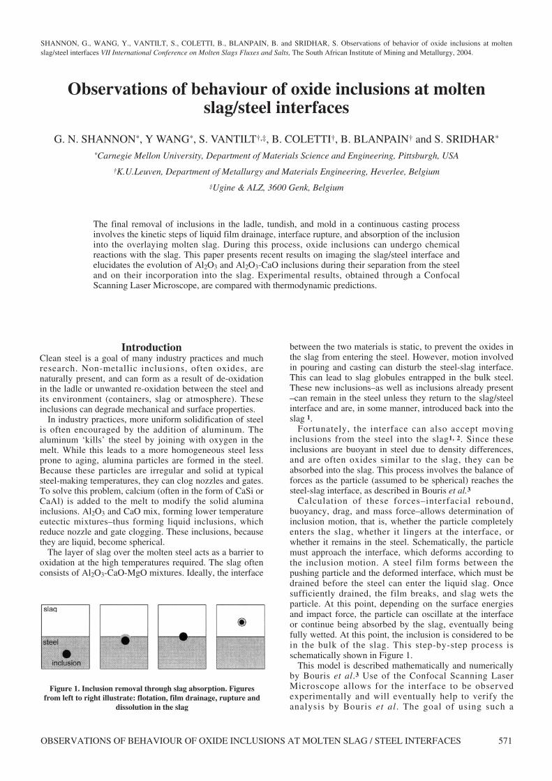
Calculation of these forces–interfacial rebound,buoyancy, drag, and mass force–allows determination ofinclusion motion, that is, whether the particle completelyenters the slag, whether it lingers at the interface, orwhether it remains in the steel. Schematically, the particlemust approach the interface, which deforms according tothe inclusion motion. A steel film forms between thepushing particle and the deformed interface, which must bedrained before the steel can enter the liquid slag. Oncesufficiently drained, the film breaks, and slag wets theparticle. At this point, depending on the surface energiesand impact force, the particle can oscillate at the interfaceor continue being absorbed by the slag, eventually beingfully wetted. At this point, the inclusion is considered to bein the bulk of the slag. This step-by-step process isschematically shown in Figure 1.
This model is described mathematically and numericallyby Bouris et al.3 Use of the Confocal Scanning LaserMicroscope allows for the interface to be observedexperimentally and will eventually help to verify theanalysis by Bouris et al. The goal of using such a
SHANNON, G., WANG, Y., VANTILT, S., COLETTI, B., BLANPAIN, B. and SRIDHAR, S. Observations of behavior of oxide inclusions at moltenslag/steel interfaces VII International Conference on Molten Slags Fluxes and Salts, The South African Institute of Mining and Metallurgy, 2004.
Observations of behaviour of oxide inclusions at moltenslag/steel interfaces
G. N. SHANNON*, Y WANG*, S. VANTILT†,‡, B. COLETTI†, B. BLANPAIN† and S. SRIDHAR*
*Carnegie Mellon University, Department of Materials Science and Engineering, Pittsburgh, USA
†K.U.Leuven, Department of Metallurgy and Materials Engineering, Heverlee, Belgium
‡Ugine & ALZ, 3600 Genk, Belgium
The final removal of inclusions in the ladle, tundish, and mold in a continuous casting processinvolves the kinetic steps of liquid film drainage, interface rupture, and absorption of the inclusioninto the overlaying molten slag. During this process, oxide inclusions can undergo chemicalreactions with the slag. This paper presents recent results on imaging the slag/steel interface andelucidates the evolution of Al2O3 and Al2O3-CaO inclusions during their separation from the steeland on their incorporation into the slag. Experimental results, obtained through a ConfocalScanning Laser Microscope, are compared with thermodynamic predictions.
Figure 1. Inclusion removal through slag absorption. Figuresfrom left to right illustrate: flotation, film drainage, rupture and
dissolution in the slag

MOLTEN SLAGS FLUXES AND SALTS572
microscope is to observe the motion of particles as theyinitially emerge from the slag/steel interface, and anyrelated phenomenon–shape change, size change, etc.
Because these forces can become quite complex,particularly if flow is assumed to exist in the steel or slag, amulti-physics computational model may better describe there-entrainment of inclusions into the slag. The model usedin Bouris et al. 3 does not take into account electrostaticforces, which may be present in this situation, since theliquid oxides consist of free ions. This force may affect thebreaking of the steel film, a process which should beinvestigated. Furthermore, if the slag contains oxides thatare less stable than alloying elements in the steel melts, re-oxidation might result in changes in the inclusion chemistryand morphology.
Materials and experimental procedureThe primary method of investigation of this process is theConfocal Scanning Laser Microscope (CSLM). Due to the
emission of radiation at visible wavelengths and to theirregularity of the surface, viewing a molten steel surfacethrough conventional optical microscopy or electronmicroscopy is difficult. CSLM provides sharp images ofuneven surfaces through its confocal optics and real timeimaging1. The laser light source enhances thesignal/background radiation ratio. The CLSM is positionedabove an insulated chamber where the sample is melted bymeans of radiation through gold mirrors reflecting lightfrom a halogen bulb. The CSLM scans the molten slag/steelinterface with a laser, and the resulting image iscontinuously exported to a super-VHS video recorder. Themicroscope setup is shown in Figure 2, with the sampleholder and specimen chamber shown in Figure 3. As shownin Figure 3, the system is equipped with a gas purificationtrain consisting of dryerite, and heated Mg and Cu chips,and the oxygen content in the off gas is monitored with asolid state ceramic oxygen sensor. Ultrapure argon gas wasused to purge the specimen chamber.
The experimental procedure included a pre-melting andhomogenization of the slag powder within a 5 mm Al2O3crucible, held for about ten minutes at 1600ºC, after whichthe sample was cooled to room temperature. Subsequently,a small disk of steel was added on top of the slag. Theslag/steel sample was then heated and behaviour of the steeland steel-slag interface was observed. The laser-scannedimages were recorded onto VHS, along with information onsample magnification, temperature, and relative time. Thesemovies were exported and examined in a software package,MGI Videowave, which allows capture of individualframes. Study of these frames provided information oninclusion size, shape, separation distance, and movement. Aplot of the separation distance versus time for two particlesis shown in Figure 11.
Once cooled, the samples are mounted, then ground andpolished by hand. Enough grinding is done in order toobtain a cross-section of the final state of the steel and slag.This scheme allows for easy observation of several featuresand important areas–the bulk steel, the bulk slag, and thefinal steel-slag interface. An example is shown in Figure 4.
Figure 2. Confocal laser scanning microscope setup
Figure 3. Sample holder (a) and specimen chamber on CSLM (b)
(a) (b)
Table IInitial inclusions in steel (from EDS)
CaO Al2O3 MgO43% 55% 2%

OBSERVATIONS OF BEHAVIOUR OF OXIDE INCLUSIONS AT MOLTEN SLAG / STEEL INTERFACES 573
In addition to this regular procedure for using the CSLM,a verification run was done using identical slag powderwith a small amount of calcia-alumina powder to simulatesteel inclusions without steel. Its composition is: 50.18 at%CaO, 49.63 at% Al2O3, plus trace elements. An additionalpoint for this simulated inclusion is added to Figure 5a, aphase diagram showing compositions for inclusions foundin the steel using chemical analysis. Otherwise, the CSLMwas run using steps and parameters identical to the otherexperiments. The surface of the sample was observed to seeif and when the substitute inclusions dissolved in the bulkslag.
Scanning electron microscopy (SEM), using a PhilipsXL-30, was carried out to characterize the samples. Areasof interest included inclusions in the bulk steel and the slag-steel interface. This allowed a post-melt view of the sample,and hopefully of the remaining inclusions–their shape,distribution, and relation to the slag/steel interface. In orderto determine the compositions in various areas of thesample, energy dispersive spectroscopy (EDS) is used. TheEDS device is attached to the Philips XL-30. Areas ofinterest included the bulk steel, bulk slag, and anyinclusions found within those phases and at the slag/steelinterface. Comparing these compositions with the initialcompositions of the steel, inclusions, and slag can provideinformation on how each of these phases changed throughthe experiment. EDS was also used to determine thestarting compositions of the inclusions in the steel, which islisted in Table I.
The steel used in these experiments is a low-carbon,aluminum-killed and calcium-treated steel provided bySiderar (San Nicholas, Argentina). The steel samples weretaken after the ladle treatment. Their chemical compositionhas been verified previously 4, and is described in Table II.Inclusion analysis of the steel samples is shown in Figure5a (composition) and Figure 5b (size distribution). The slagused in this experiment is a calcia-alumina-silica-magnesia
mixture. Its composition, from previous chemical analysis,is listed in Table III.
Results and discussionsWhen a top-covering slag was not used, the inclusions onthe surface of molten steel were spherical inclusions ofsizes similar to those found in the starting sample (Figure5b). A typical example is shown in Figure 6a. In thepresence of a slag the inclusions were remarkably different.
Figure 4. Photograph of a cross-section of a sampleFigure 5a. Initial inclusion composition (♦ denotes composition of
substituted calcia-alumina inclusions)
Figure 5b - Initial inclusion size distribution
Table IISteel composition, weight percent (ODIS is dissolved oxygen, OTOT is total oxygen)
Nº
incl
usio
ns /
mm
2
Equivalent diameter (�m)
Table IIIInitial slag composition (from EDS)
C S Al Ca Si Mn P ODIS OTOT
0.062 0.014 0.027 0.002 0.033 0.33 0.013 0.0002 0.003
SiO2 CaO Al2O3 MgO39.5% 33.4% 19.5% 7.3%

MOLTEN SLAGS FLUXES AND SALTS574
The inclusions that were seen to emerge from the steel intothe slag side were irregular to start with, as shown in Figure6b. Separation into the slag side occurred in less than asecond but far longer than a micro-second predicted bypublished models3. The inclusions varied in size, fromroughly 5 microns to 30 microns. The inclusions evolved intwo ways. Firstly, the irregular inclusions were found tochange into spherical shapes as shown in Figure 7. Thisspheroidization process would take a few seconds tocomplete as shown. Secondly, inclusions were found toagglomerate and form clusters as shown in Figure 8.Typically, the fully spherical particles did not join together.
SEM-EDS analysis of inclusions found near the slag/steelinterface revealed that the inclusions consisted of 41.7 wt%SiO2, 22.3 wt% CaO, 30.5 wt% Al2O3 and 5.5 wt% MgO. Itis of course difficult to assess how/if the inclusionsobserved at high temperatures changed during cooling andsolidification, but the results indicate that the originalinclusions have significantly gained SiO2 from the slag butlost CaO.
It is noteworthy that the absorption of particles into theslag was not observed and yet the inclusions observed havea distinctly different chemistry from the slags. This couldbe caused if a solid reaction layer existed at theinclusion/slag interface that did not allow for a directdissolution but rather a reaction between the slag andinclusion that was limited by solid state diffusion. Such asolid film could be formed on the surface of the inclusionsduring the separation process of the inclusion across theslag metal interface. The separation process is thought toinvolve the kinetic steps of steel film drainage and rupture.It should furthermore be noted that the slag phase is
saturated with respect to Al2O3 due to the container andthus the dissolution of Al2O3 expected to be slow. A similarphenomenon, where inclusions did not dissolve afterseparation into the slag, was recently observed for severalother slag/steel systems5.
This appears to contradict the verification experiment, inwhich calcia-alumina powder, to simulate inclusions similarto composition to those in the steel used above, and theoriginal slag material were melted together. In thisexperiment, the substitute inclusions dissolvedimmediately, and no definite presence of opaque particlescould be seen afterwards. Because the slags, in bothexperiments, were homogenized for several minutes at1600ºC in an alumina crucible, they should contain asoluble limit of alumina, and the particles should notdissolve as readily as they appear to.
While the compositions of the steel inclusions and thesubstitute inclusions are similar, there are enoughdifferences that there may be some important experimentaldifference that causes this apparently contradictory result.The presence of the slag/steel interface may, as mentionedabove, form a solid reaction layer that assists in preventingsteel inclusions from dissolving, at least for the timesobserved. This would not be so using substitute inclusions,thus allowing their ready dissolution.
Yin et al. found that an alumina inclusion is partiallyimmersed at the surface of liquid steel and that a singleparticle will depress the liquid level around it6, 7. If twoparticles approach one another, the meniscus in between isfurther depressed. This leads to a difference in capillarypressure between the area outside and between theinclusions. If the pressure is lower in the zone between the
Figure 6. Typical inclusions observed through CSLM at (a) a molten steel surface and (b) a molten steel/slag interface
Figure 7. Transformation of solid, irregular inclusion to spherical
(a) (b)

OBSERVATIONS OF BEHAVIOUR OF OXIDE INCLUSIONS AT MOLTEN SLAG / STEEL INTERFACES 575
inclusions, both particles are pushed together. Thismechanism of capillary interaction is believed to be thesource of the attraction between alumina inclusions at thesurface and the bulk of liquid steel. In the case of liquidinclusions, however, it was found that the depression wastoo small to cause a sufficiently large force for clustering.The spherical inclusions that emerge at the interface likelycontained significant amounts of liquid at the experimentaltemperatures. The fact that no clustering is observed forspherical inclusions is thus in agreement with earlierobservations. Capillary depression is, however, unlikely tohave a significant role in the clustering at the slag/steelinterface since oxide inclusions are likely to wet the moltenoxide slag layer rather than depress the steel meniscus.
For the cases where inclusion clustering occurred at theslag/steel interfaces, the particle-cluster distance as afunction of time was determined for the cluster-formingsteel-slag systems. Clustering was observed betweenparticles and clusters but not between 2 individual particles.It was found that the initial velocity was high but eventuallythe inclusion slowed down as it approached the cluster.
This is in contradiction to capillary depression drivenclustering where the force would increase as the distancebetween particles became smaller. The inclusions movetowards each other, initially at high velocity, slow downand stabilize at a certain distance from one another. Thus, itseems that an attractive force works at longer distance but arepulsive force counteracts it at shorter distance. It is likelythat the inclusions float up along the surface of the steelcaused by their lower density in comparison with steel.
During the steel-slag experiments the steel forms adroplet immersed into slag and the inclusions rise to the
highest point of the steel droplet due to buoyancy forces.This cannot be observed in the experiments in the absenceof slag because the steel surface is almost flat during thosetests. After the inclusions are brought together some effectprevents them from making contact. If the particles movetowards each other, the steel layer in between has to bedrained. Hydrodynamic forces are important during thisprocess and the closer the inclusions get, the slower theremoval of the steel goes. The drainage of the steel film canslow down the moving inclusions significantly.
On cooling, near the slag solidification temperature, itwas sometimes seen that a large number of irregular, 5micron particles spread over the surface andagglomerated. These particles have a flower-likemorphology. These agglomerations, both just before andjust after freezing, are shown in Figure 9.
An example of an inclusion under SEM is shown inFigure 10. In this image, the sample had been broken toremove the solidified steel, and this inclusion was foundwhere the steel had been removed from the slag. Becausethe sample must be either broken or cross-sectioned inorder to view it under SEM, it is difficult to properly findinclusions that sett led at the slag/steel interface.However, this particle seems likely to be a clusteredinclusion, possibly the agglomerated ones mentionedabove. An EDS scan of the particle showed it to besimilar to the original inclusion composition. Smaller,non-agglomerated inclusions were spherical or nearlyspherical within the steel, while others were largelyirregular. Because the steel solidified before theinclusions inside the steel solidified (because of the
a) (b)
a) (b)
Figure 8. Joining of particles
Figure 9. Flower-like agglomerations on the steel/slag surface during cooling

MOLTEN SLAGS FLUXES AND SALTS576
calcium treatment, they should be l iquid at thetemperature reached), the inclusions had to assume theshape imposed by the solid steel, and thus were spherical.As stated previously, inclusions can undergo manypossible reactions once outside the bulk steel, so theirshape can be due to a number of different forces.
SummaryThe behavior of Al2O3-CaO inclusions at a molten Alkilled, Ca-treated steel/Al2O3-CaO-MgO-SiO2 interfacewas visualized through a Confocal Scanning LaserMicroscope equipped with a gold image furnace. It wasfound that:
(i) Upon separation into the slag, the inclusions didnot readily dissolve in the slag upon separation
(ii) The separated inclusions were irregular andenriched in SiO2 but depleted in CaO due toreactions with the slag phase
(iii) Irregular inclusions did undergo agglomerationdriven by hydrodynamic forces.
AcknowledgementsFinancial support from NSF (DMR 0112792) and costsharing from Carnegie Mellon University are greatlyacknowledged. Technical support and experimentalfacilities of the Center for Iron and Steelmaking Researchwas used to carry out parts of the experimental work.
References1. MISRA, P., CHEVRIER, V., SRIDHAR, S., and
CRAMB, A.W. In Situ Observations of Inclusions at the(Mn, Si)-Killed Steel / CaO-Al2O3Interface.Metallurgical and Materials Transactions B,vol. 31B, October, 2000. pp. 1135–1139.
2. ROCABOIS, P., LEHMANN, J., GATELLIER, C., andTERES, J.P. Non-metallic Inclusion Entrapment bySlags: Laboratory Investigation. Ironmaking andSteelmaking, vol. 30, no. 2. 2003. pp. 95–100.
3. BOURIS, D., and BERGELES, G. Investigation ofInclusion Re-Entrainment from the Steel-Slag Interface.Metallurgical and Materials Transactions B, vol. 29B,June, 1998. pp. 641–649.
4. WANG, Y., VALDEZ, M., and SRIDHAR, S.Formation of CaS on Al2O3-CaO Inclusions duringSolidification of Steels. Metallurgical and MaterialsTransactions B, vol. 33B, August, 2002. pp. 625–632.
5. COLETTI, B., VANTILT, S., BLANPAIN, B.,SRIDHAR, S. Observation of calcium aluminateinclusions at interfaces of Ca-treated, Al-killed steelsand slags, in press Metallurgical and MaterialsTransactions B.
6. YIN, H., SHIBATA, H., EMI, T., and SUZUKI, M. Insitu observation of collision, agglomeration and clusterformation of alumina inclusion particles on steel melts.ISIJ Int., vol. 37, no. 10, 1997. pp. 936–945
7. H. YIN, H. SHIBATA, T. EMI and M. SUZUKI.Characteristics of agglomeration of various inclusionparticles on molten steel surface. ISIJ Int., vol. 37, no.10. 1997. pp. 946–955.
Figure 10. Clustered inclusions from separated steel/slaginterface
time (sec.)
sepe
ratio
n di
stan
ce (
mic
rons
)
Figure 11. Seperation distance between inclusions