Molten Salts and Applications III: Worldwide Molten Salt … · 2019-02-22 · Molten Salts and...
12
Journal of Energy and Power Engineering 12 (2018) 533-544 doi: 10.17265/1934-8975/2018.11.003 Molten Salts and Applications III: Worldwide Molten Salt Technology Developments in Energy Production and Storage Samaan Ladkany, William Culbreth and Nathan Loyd Howard Hughes College of Engineering, University of Nevada, Las Vegas, Las Vegas, NV 89154, USA Abstract: Supported by Office of Naval Research (ONR), this paper presents a survey of molten salt technology used in solar power storage. Excess energy from solar power stations and other baseline power production methods can be stored in molten salts (MS) in the 565°C range, therefore allowing the use of large containers to store energy for up to a week and generate eight hours of electricity or more to be used during peak demand hours, at night, or adverse weather conditions, depending on the container size. The technology could also be used to conserve the spin off energy in the grids from nuclear or coal power production. Real life examples of concentrating solar power (CSP) plants, both domestically and worldwide, are presented with details about the type of solar collection, capacity, and energy production. Commercial solar power stations have been constructed in the United States and overseas, particularly in Spain, with molten salt being considered for use in these facilities. Some facilities use a field of flat mirrors and collection towers while others use parabolic troughs. Key words: Molten salts, molten salt storage systems, molten salt developments, molten salt applications, energy storage, solar energy. 1. Introduction Molten solar salts have considerable heat storage capacities, and as such, they are an effective way to store excess generated energy for later use. These salts are contained by storing the solar salts in a closed system that includes large insulated tanks. This paper examines the current methods of using insulated stainless steel cylindrical shells to store molten salt. A catalogue of past and present solar power plants in the U.S. that have employed Molten Salt (MS) for electric power production is presented. The material presented in this paper has been collected by the researchers in the UNLV Molten Salt Project and information provided by Dr. Craig Tyner in a report to the project [1, 2]. This is the third paper in a series on Molten Salt Research, preceded by “Molten Salt History, Types, Corresponding author: Dr. Craig Tyner, Ph.D. in Chemical Engineering, consultant and former CEO of Halotechnics, research fields: concentrating solar power and molten salts. Thermodynamic and Physical Properties, and Cost” [3] and “565 °C Molten Salt Solar Energy Storage Design, Corrosion, and Insulation” [4]. 2. High Temperature Systems All solar salt systems discussed in this paper are based on nitrate salts or thermal oils and have an upper temperature limit of about 565 ºC or less. Because the efficiency of power cycles increases with increasing temperature gradients, there have long been efforts to develop higher temperature systems. Pushing temperatures above 600-650 ºC, for example, would allow use of the more efficient modern steam turbines than the ones operating at 585 ºC or so. Temperatures up to 800 ºC would allow use of Stirling engines (typically in parabolic dish systems), and temperatures above 900-1,000 ºC could theoretically allow use of Brayton or combined cycles. Working fluids considered have included air, steam, and other molten salts. Several issues have kept these efforts from commercial success, however. First, D DAVID PUBLISHING
Transcript of Molten Salts and Applications III: Worldwide Molten Salt … · 2019-02-22 · Molten Salts and...
Journal of Energy and Power Engineering 12 (2018) 533-544 doi: 10.17265/1934-8975/2018.11.003
Molten Salts and Applications III: Worldwide Molten Salt Technology Developments in Energy Production and
Storage
Samaan Ladkany, William Culbreth and Nathan Loyd
Howard Hughes College of Engineering, University of Nevada, Las Vegas, Las Vegas, NV 89154, USA Abstract: Supported by Office of Naval Research (ONR), this paper presents a survey of molten salt technology used in solar power storage. Excess energy from solar power stations and other baseline power production methods can be stored in molten salts (MS) in the 565°C range, therefore allowing the use of large containers to store energy for up to a week and generate eight hours of electricity or more to be used during peak demand hours, at night, or adverse weather conditions, depending on the container size. The technology could also be used to conserve the spin off energy in the grids from nuclear or coal power production. Real life examples of concentrating solar power (CSP) plants, both domestically and worldwide, are presented with details about the type of solar collection, capacity, and energy production. Commercial solar power stations have been constructed in the United States and overseas, particularly in Spain, with molten salt being considered for use in these facilities. Some facilities use a field of flat mirrors and collection towers while others use parabolic troughs. Key words: Molten salts, molten salt storage systems, molten salt developments, molten salt applications, energy storage, solar energy.
1. Introduction
Molten solar salts have considerable heat storage capacities, and as such, they are an effective way to store excess generated energy for later use. These salts are contained by storing the solar salts in a closed system that includes large insulated tanks. This paper examines the current methods of using insulated stainless steel cylindrical shells to store molten salt. A catalogue of past and present solar power plants in the U.S. that have employed Molten Salt (MS) for electric power production is presented. The material presented in this paper has been collected by the researchers in the UNLV Molten Salt Project and information provided by Dr. Craig Tyner in a report to the project [1, 2].
This is the third paper in a series on Molten Salt Research, preceded by “Molten Salt History, Types,
Corresponding author: Dr. Craig Tyner, Ph.D. in Chemical
Engineering, consultant and former CEO of Halotechnics, research fields: concentrating solar power and molten salts.
Thermodynamic and Physical Properties, and Cost” [3] and “565 °C Molten Salt Solar Energy Storage Design, Corrosion, and Insulation” [4].
2. High Temperature Systems
All solar salt systems discussed in this paper are based on nitrate salts or thermal oils and have an upper temperature limit of about 565 ºC or less. Because the efficiency of power cycles increases with increasing temperature gradients, there have long been efforts to develop higher temperature systems. Pushing temperatures above 600-650 ºC, for example, would allow use of the more efficient modern steam turbines than the ones operating at 585 ºC or so. Temperatures up to 800 ºC would allow use of Stirling engines (typically in parabolic dish systems), and temperatures above 900-1,000 ºC could theoretically allow use of Brayton or combined cycles.
Working fluids considered have included air, steam, and other molten salts. Several issues have kept these efforts from commercial success, however. First,
D DAVID PUBLISHING

Molten Salts and Applications III: Worldwide Molten Salt Technology Developments in Energy Production and Storage
534
higher working solar temperatures generally mean higher radiative and convective thermal losses, offsetting some of the gains of the higher efficiency cycles. Very high solar concentration ratios combined with volumetric air receivers and/or thermally selective coatings, such as cermaics and sintered metals (cermets), can mitigate this effect by significantly reducing radiative losses at any given temperature to some extent, but large-scale success at high temperature has been limited.
Secondly, materials limitations at higher temperatures have been difficult to overcome. While ceramics are useful at very high temperatures, there has been very limited success incorporating them in solar receivers due to joining and brittleness issues. While some metals can operate beyond the 670-700 ºC wall temperatures of today’s power tower receivers, those receivers are generally already designed at the material limits of the most promising alloys (e.g., Inconels and Haynes materials) due to the high thermal stresses induced at high solar fluxes and to potential corrosion issues.
Finally, working and storage fluids themselves have various limitations. Nitrate salts (< 600 ºC) and thermal oils (< 400 ºC) decompose, while carbonates (600-900 ºC) tend to be extremely corrosive. Chloride-based salts (< 700 ºC) and molten glasses (< 1,200 ºC) are being considered, but they remain largely unproven in solar applications. Ceramics, rocks, and concrete have all been demonstrated successfully as storage materials up to about 1,000 ºC (usually with air as the working fluid), but air receivers and systems issues have prevented commercialization.
3. Solar Salt Technology
Power tower and parabolic trough plants share many common characteristics, but have some significant differences, as well. Molten Salt Electrical Storage Systems (MS-ESS) are available with either technology, although via different routes.
In a power tower configuration, the molten salt
serves as both the working fluid and the storage fluid. Solar salt liquefies between 225 °C and 240 °C, then the “Cold” salt at about 285 ºC is pumped from the cold storage tank to the receiver, where it is heated to about 565 ºC. This “hot” salt is then returned to the hot storage tank. When needed for power production, hot salt is then pumped to the MS steam generator, producing 550 ºC steam to drive a conventional reheat steam turbine. The cold salt is returned to the cold tank to repeat the process.
In commercial parabolic trough systems, MS is used only as a storage fluid. Synthetic oil is circulated through the solar field, typically being heated to about 400 ºC, a limit imposed by a variety of factors including thermal stability of the oil, vapor pressure of oil at high temperatures, and the relatively low (80-100) sun concentration ratios of troughs which results in correspondingly higher thermal losses. The hot oil is then used in a steam generator to produce steam for the reheat steam turbine. In a trough plant with MS storage, excess solar thermal capacity (beyond what the turbine can use directly) is transferred from the oil to molten salt in conventional heat exchangers. Hot salt (at close to 400 ºC) is then stored until needed, at which time the same heat exchangers are used to heat cold oil back to 400 ºC, to be used in the steam generators. Cold salt at about 285 ºC is then returned to the cold storage tank. Note that the temperature differential (the “ΔT”) between hot and cold salt for trough systems is limited to about 115 ºC compared to the power tower ΔT of about 280 ºC. Thus, significantly more salt is required for the same amount of storage in trough systems, resulting in higher storage costs. This increase is only minimally offset by less expensive containment materials for 400 ºC hot salt, as discussed below.
Both of the above mentioned approaches utilize two separate tanks, a “cold” tank and a “hot” tank. Some work has been done on an alternative approach using a single “thermocline” tank, as a possible approach to cost reduction. Pacheco et al. [5] discussed the concept and the related testing done at Sandia. In a thermocline
Molten Salts and Applications III: Worldwide Molten Salt Technology Developments in Energy Production and Storage
535
system, a single large tank is filled with some type of ceramic material (a mixture of quartzite and filter silica sand was used in testing by Sandia) which is less expensive than solar salt, and then filled with solar salt. In operation, cold salt (which is denser than hot salt) is drawn off the bottom of the tank to be heated in the receiver and returned to the top of the tank. To generate steam, hot salt is pumped from the top of the tank and returned cold to the bottom. The relative volumes of hot and cold salt vary, with the hot zone on top expanding downward to fill the tank during charging, and the cold salt expanding upward during power generation. The filler material serves to minimize the salt required, while still maintaining the thermal storage capacity of a salt-filled tank. In theory, this approach results in savings of the cost of building a cold tank (the thermocline tank must hold hot salt, and thus requires hot salt design and materials) and the cost differential between filler and salt (assuming filler is cheaper than salt).
There are, however, two significant disadvantages to the thermocline approach. First, the demarcation between cold and hot salt is never sharp, meaning there is a zone of intermediate temperature between the hot and cold that serves to decrease system capacity and efficiency somewhat. Second, the entire tank cycles between hot and cold every day, perhaps impacting tank life to some extent, but more importantly, allowing the filler to settle when the tank is hot (and expanded). When returned to the cold state, the filler cannot reestablish its original packing density, but rather become more densely packed with each cycle. Ultimately, this ratcheting can crush the filler particles and/or plastically deform the tank, perhaps ultimately to the point of failure. Thus, despite its promise and some significant interest in its use, thermocline storage has yet to be demonstrated on a commercial scale.
An interesting “cascading tank” alternative to the two-tank and thermocline approaches, is discussed in more detail below, under Off-Grid Applications. This system has yet to be built and tested.
4. Off Grid Applications
To date, successful commercial concentrating solar power plant (CSP) systems have been limited essentially exclusively to large, grid-connected plants. While smaller, off-grid applications (OGAs) have long been considered for military, village power, mining, or other industrial applications (using primarily dish/engine or small parabolic trough systems), the dramatic reductions in photovoltaic system cost over the past decade have largely eliminated this option—with one notable exception: off-grid systems requiring storage. Batteries can provide limited (and to date very expensive) storage for PV in a range of situations, but cannot yet provide cost-competitive storage for larger systems.
Off-grid and remote applications with MS storage for military use are, of course, possible, although a number of hurdles would have to be overcome. While conventional (fossil fuel-powered) OGAs can be very expensive on a per kWh basis (depending on fuel transportation and operations and maintenance (O&M) costs), the leveled cost of energy (LCOE) tends to increase rapidly in smaller CSP systems. For example, a 10- MWe plant would likely have twice the LCOE of a 100-MWe plant, even with comparable solar and storage technologies. In addition to the simple economies-of-scale effects, this cost issue is exacerbated by inherently lower efficiencies of turbines commercially available in smaller sizes (relative, for example, to the 42-43% overall efficiencies of modern 100-MWe reheat steam turbines).
With MS-ESSs, a second issue has to do with salt freezing during any extended plant outage. With large grid-connected systems, salt in large tanks can go for weeks (or even months) without worries about freezing, and piping can be kept above salt freezing temperatures with electric heat trace. Off-grid, however, without inexpensive back up power and with potentially much smaller tanks, salt freezing is a serious and potentially costly issue to deal with during plant outages.
Molten Salts and Applications III: Worldwide Molten Salt Technology Developments in Energy Production and Storage
536
Finally, even with storage, CSP is not always available on demand. In a typical “maximum storage” (75% capacity factor) design, power can be available 24/7 during summer months, as long as the sun is shining consistently. With cloudy weather, availability is of course lessened (and even the best sites have a significant amount of poor solar availability), and typically drops to 50% or less in winter months because of the shorter days. Bottom line: MS-ESSs can provide hours of storage, but not enough to get through significant weather outages and certainly not seasonal storage.
That said, small OGAs based on CSP and MS-ESS are still possible. Trough systems can be scaled down to nearly any size (remembering the cost and efficiency penalties, of course). Tower systems generally scale less effectively, with eSolar’s modular design being somewhat of an exception. eSolar’s base module is 50 MWt, meaning a single module plant could be as small as about 8-10 MWe with an annual capacity factor of 45-50%. Storage systems themselves can also scale over this range, remembering again the economies-of-scale and salt freezing issues.
5. Performance of Molten Salt Systems
Large two-tank molten salt storage systems have consistently demonstrated average annual thermal efficiencies of about 99%. This is largely because the design temperatures of the storage system were chosen to match very closely the requirements of steam needed for modern steam turbines. Because of the very large sizes of these systems, losses are limited to the relatively very small thermal losses associated with the tank walls and related system piping and pumping losses associated with pumping salt into and out of the tanks.
For example, a 50% capacity factor, 100-MWe power tower plant would require roughly 15,000 to 20,000 metric tonnes of salt, a 75% capacity factor plant up to 35,000 tonnes. To accommodate this much salt, the hot and cold storage tanks at Crescent Dunes
are, for example, each over 12 m tall and over 40 m in diameter. Tanks at Andasol are similar in size, although they hold fewer MWh because of the lower temperature differential available in trough systems. At Abengoa’s Solana plant, there are 6 each hot and cold tanks instead of a single tank for each temperature.
Effects of Heat Losses: When considering thermal losses for storage tanks, the largest contributor of heat loss is contact with the ground. However, the shape of the storage tank can provide some differences in heat losses. For example, thermal losses in theory could be reduced with large spherical tanks, when compared to large cylindrical tanks. Another factor would be the wind effect on heat losses from an MS tank, thus other factors, such as tank exterior insulation being equal, research into an aerodynamic tank shape that reduces the wind chill factor and minimizing the heat losses through contact with ground, may be worthy topics to investigate [1, 6].
6. Worldwide Molten Salt Installations
After the development of Solar Two in 1993, MS-ESS technology has evolved and accelerated worldwide, as there are currently 44 MS-ESS plants either operational or under construction, as well as 24 more plants in the planning stages. The success of Solar Two led to two development paths: power towers based directly on the Solar Two design and the addition of MS-based storage to commercially proven parabolic trough plants. Table 1 lists all U.S. CSP plants in operation or construction.
The first near-commercial power tower plant utilizing MS storage was the 20-MWe Gemasolar plant developed by Sener/Torresol in Andalucía, Spain. The original Gemasolar concept (dubbed Solar Tres) involved participation of U.S. companies which had been suppliers for Solar Two (Boeing/Rocketdyne (receiver supplier) and Bechtel/Nexant (EPC)), although Gemasolar was ultimately built without any U.S. involvement. Gemasolar is roughly a factor of 3 scale-up of Solar Two (120 MW thermal (MWt) vs. 43
Molten Salts and Applications III: Worldwide Molten Salt Technology Developments in Energy Production and Storage
537
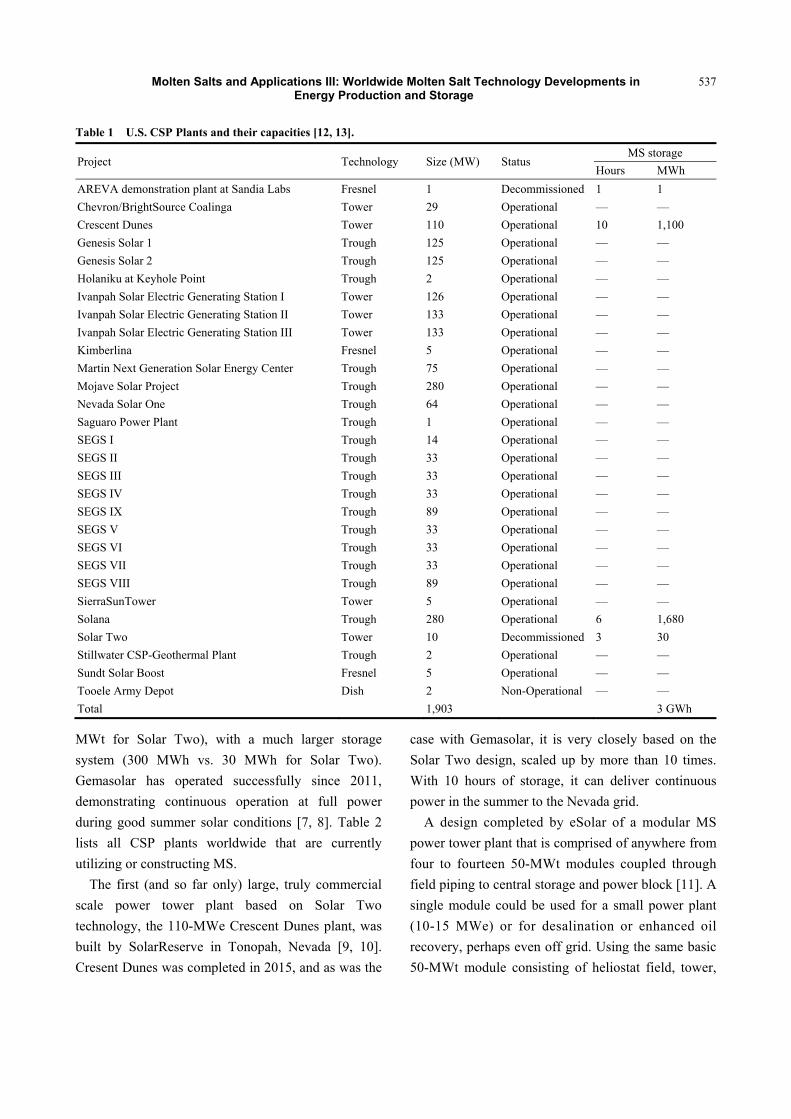
Table 1 U.S. CSP Plants and their capacities [12, 13].
Project Technology Size (MW) Status MS storage
Hours MWh AREVA demonstration plant at Sandia Labs Fresnel 1 Decommissioned 1 1 Chevron/BrightSource Coalinga Tower 29 Operational — — Crescent Dunes Tower 110 Operational 10 1,100 Genesis Solar 1 Trough 125 Operational — — Genesis Solar 2 Trough 125 Operational — — Holaniku at Keyhole Point Trough 2 Operational — — Ivanpah Solar Electric Generating Station I Tower 126 Operational — — Ivanpah Solar Electric Generating Station II Tower 133 Operational — — Ivanpah Solar Electric Generating Station III Tower 133 Operational — — Kimberlina Fresnel 5 Operational — — Martin Next Generation Solar Energy Center Trough 75 Operational — — Mojave Solar Project Trough 280 Operational — — Nevada Solar One Trough 64 Operational — — Saguaro Power Plant Trough 1 Operational — — SEGS I Trough 14 Operational — — SEGS II Trough 33 Operational — — SEGS III Trough 33 Operational — — SEGS IV Trough 33 Operational — — SEGS IX Trough 89 Operational — — SEGS V Trough 33 Operational — — SEGS VI Trough 33 Operational — — SEGS VII Trough 33 Operational — — SEGS VIII Trough 89 Operational — — SierraSunTower Tower 5 Operational — — Solana Trough 280 Operational 6 1,680 Solar Two Tower 10 Decommissioned 3 30 Stillwater CSP-Geothermal Plant Trough 2 Operational — — Sundt Solar Boost Fresnel 5 Operational — — Tooele Army Depot Dish 2 Non-Operational — — Total 1,903 3 GWh
MWt for Solar Two), with a much larger storage system (300 MWh vs. 30 MWh for Solar Two). Gemasolar has operated successfully since 2011, demonstrating continuous operation at full power during good summer solar conditions [7, 8]. Table 2 lists all CSP plants worldwide that are currently utilizing or constructing MS.
The first (and so far only) large, truly commercial scale power tower plant based on Solar Two technology, the 110-MWe Crescent Dunes plant, was built by SolarReserve in Tonopah, Nevada [9, 10]. Cresent Dunes was completed in 2015, and as was the
case with Gemasolar, it is very closely based on the Solar Two design, scaled up by more than 10 times. With 10 hours of storage, it can deliver continuous power in the summer to the Nevada grid.
A design completed by eSolar of a modular MS power tower plant that is comprised of anywhere from four to fourteen 50-MWt modules coupled through field piping to central storage and power block [11]. A single module could be used for a small power plant (10-15 MWe) or for desalination or enhanced oil recovery, perhaps even off grid. Using the same basic 50-MWt module consisting of heliostat field, tower,

Molten Salts and Applications III: Worldwide Molten Salt Technology Developments in Energy Production and Storage
538
Table 2 Current worldwide molten salt CSP Plants and their capacities [12, 13].
Project Country Technology Size (MW) Status MS storage Hours MWh
Atacama-1 Tower Chile 110 Construction 17.5 1,925 Golmud Tower China 200 Construction 15.0 3,000 Hami Tower China 50 Construction 8.0 400 Huanghe Qinghai Delingha Tower China 135 Construction 3.7 500 Qinghai Delingha Trough China 50 Construction 9.0 450 Rayspower Yumen Trough China 50 Construction 7.0 350 SunCan Dunhuang Phase I Tower China 10 Operational 15.0 150 SunCan Dunhuang Phase II Tower China 100 Construction 11.0 1,100 Supcon Tower China 50 Construction 2.5 125 Urat Middle Banner Trough China 100 Construction 4.0 400 Yumen 50 MW Tower Tower China 50 Construction 9.0 450 Archimede Trough Italy 5 Operational 8.0 40 ASE Demo Plant Trough Italy 2 Operational 1.0 2 Noor I Trough Morocco 160 Operational 3.0 480 Noor II Trough Morocco 200 Operational 7.0 1,400 Noor III Trough Morocco 150 Construction 7.0 1,050 Bokpoort Trough South Africa 50 Operational 9.3 465 Kathu Solar Park Trough South Africa 100 Operational 4.5 450 KaXu Solar One Trough South Africa 100 Operational 2.5 250 Xina Solar One Trough South Africa 100 Operational 5.5 550 Andasol 1 Trough Spain 50 Operational 7.5 375 Andasol 2 Trough Spain 50 Operational 7.5 375 Andasol 3 Trough Spain 50 Operational 7.5 375 ASTE - 1A Trough Spain 50 Operational 8.0 400 ASTE - 1B Trough Spain 50 Operational 8.0 400 Arenales Trough Spain 50 Operational 7.0 350 Astexol-2 Trough Spain 50 Operational 7.5 375 Casablanca Trough Spain 50 Operational 7.5 375 Extresol 1 Trough Spain 50 Operational 7.5 375 Extresol 2 Trough Spain 50 Operational 7.5 375 Extresol 3 Trough Spain 50 Operational 7.5 375 Gemasolar Tower Spain 20 Operational 15.0 300 La Africana Trough Spain 50 Operational 7.5 375 La Dehesa Trough Spain 50 Operational 7.5 375 La Florida Trough Spain 50 Operational 7.5 375 Manchasol 1 Trough Spain 50 Operational 7.5 375 Manchasol 2 Trough Spain 50 Operational 7.5 375 Termosol 1 Trough Spain 50 Operational 9.0 450 Termosol 2 Trough Spain 50 Operational 9.0 450 Valle 1 Trough Spain 50 Operational 7.5 375 Valle 2 Trough Spain 50 Operational 7.5 375 Greenway CSP Tower Turkey 5 Operational 1.0 5 AREVA demonstration plant Fresnel USA 1 Decommissioned 1 1 Crescent Dunes Tower USA 110 Operational 10.0 1,100 Solar Two Tower USA 10 Decommissioned 3.0 30 Solana Trough USA 280 Operational 6.0 1,680 Total 3,198 24 GWh
Molten Salts and Applications III: Worldwide Molten Salt Technology Developments in Energy Production and Storage
539
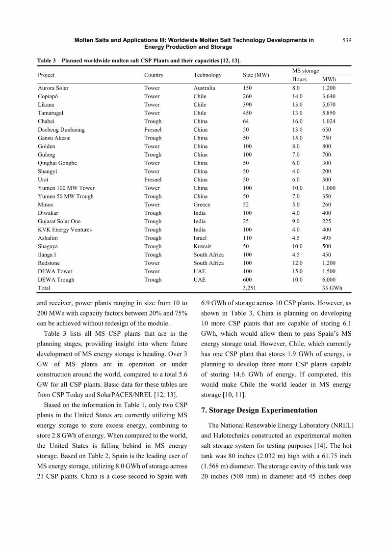
Table 3 Planned worldwide molten salt CSP Plants and their capacities [12, 13].
Project Country Technology Size (MW) MS storage Hours MWh
Aurora Solar Tower Australia 150 8.0 1,200 Copiapó Tower Chile 260 14.0 3,640 Likana Tower Chile 390 13.0 5,070 Tamarugal Tower Chile 450 13.0 5,850 Chabei Trough China 64 16.0 1,024 Dacheng Dunhuang Fresnel China 50 13.0 650 Gansu Akesai Trough China 50 15.0 750 Golden Tower China 100 8.0 800 Gulang Trough China 100 7.0 700 Qinghai Gonghe Tower China 50 6.0 300 Shangyi Tower China 50 4.0 200 Urat Fresnel China 50 6.0 300 Yumen 100 MW Tower Tower China 100 10.0 1,000 Yumen 50 MW Trough Trough China 50 7.0 350 Minos Tower Greece 52 5.0 260 Diwakar Trough India 100 4.0 400 Gujarat Solar One Trough India 25 9.0 225 KVK Energy Ventures Trough India 100 4.0 400 Ashalim Trough Israel 110 4.5 495 Shagaya Trough Kuwait 50 10.0 500 Ilanga I Trough South Africa 100 4.5 450 Redstone Tower South Africa 100 12.0 1,200 DEWA Tower Tower UAE 100 15.0 1,500 DEWA Trough Trough UAE 600 10.0 6,000 Total 3,251 33 GWh
and receiver, power plants ranging in size from 10 to 200 MWe with capacity factors between 20% and 75% can be achieved without redesign of the module.
Table 3 lists all MS CSP plants that are in the planning stages, providing insight into where future development of MS energy storage is heading. Over 3 GW of MS plants are in operation or under construction around the world, compared to a total 5.6 GW for all CSP plants. Basic data for these tables are from CSP Today and SolarPACES/NREL [12, 13].
Based on the information in Table 1, only two CSP plants in the United States are currently utilizing MS energy storage to store excess energy, combining to store 2.8 GWh of energy. When compared to the world, the United States is falling behind in MS energy storage. Based on Table 2, Spain is the leading user of MS energy storage, utilizing 8.0 GWh of storage across 21 CSP plants. China is a close second to Spain with
6.9 GWh of storage across 10 CSP plants. However, as shown in Table 3, China is planning on developing 10 more CSP plants that are capable of storing 6.1 GWh, which would allow them to pass Spain’s MS energy storage total. However, Chile, which currently has one CSP plant that stores 1.9 GWh of energy, is planning to develop three more CSP plants capable of storing 14.6 GWh of energy. If completed, this would make Chile the world leader in MS energy storage [10, 11].
7. Storage Design Experimentation
The National Renewable Energy Laboratory (NREL) and Halotechnics constructed an experimental molten salt storage system for testing purposes [14]. The hot tank was 80 inches (2.032 m) high with a 61.75 inch (1.568 m) diameter. The storage cavity of this tank was 20 inches (508 mm) in diameter and 45 inches deep
Molten Salts and Applications III: Worldwide Molten Salt Technology Developments in Energy Production and Storage
540
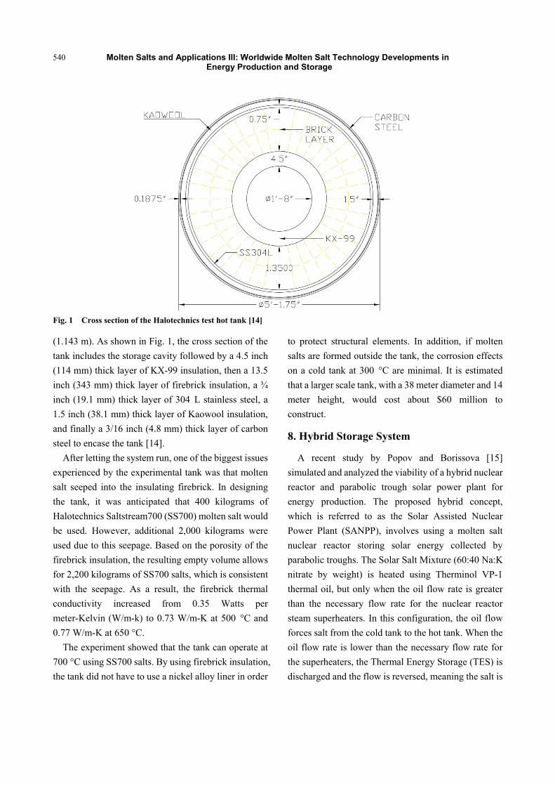
Fig. 1 Cross section of the Halotechnics test hot tank [14]
(1.143 m). As shown in Fig. 1, the cross section of the tank includes the storage cavity followed by a 4.5 inch (114 mm) thick layer of KX-99 insulation, then a 13.5 inch (343 mm) thick layer of firebrick insulation, a ¾ inch (19.1 mm) thick layer of 304 L stainless steel, a 1.5 inch (38.1 mm) thick layer of Kaowool insulation, and finally a 3/16 inch (4.8 mm) thick layer of carbon steel to encase the tank [14].
After letting the system run, one of the biggest issues experienced by the experimental tank was that molten salt seeped into the insulating firebrick. In designing the tank, it was anticipated that 400 kilograms of Halotechnics Saltstream700 (SS700) molten salt would be used. However, additional 2,000 kilograms were used due to this seepage. Based on the porosity of the firebrick insulation, the resulting empty volume allows for 2,200 kilograms of SS700 salts, which is consistent with the seepage. As a result, the firebrick thermal conductivity increased from 0.35 Watts per meter-Kelvin (W/m-k) to 0.73 W/m-K at 500 °C and 0.77 W/m-K at 650 °C.
The experiment showed that the tank can operate at 700 °C using SS700 salts. By using firebrick insulation, the tank did not have to use a nickel alloy liner in order
to protect structural elements. In addition, if molten salts are formed outside the tank, the corrosion effects on a cold tank at 300 °C are minimal. It is estimated that a larger scale tank, with a 38 meter diameter and 14 meter height, would cost about $60 million to construct.
8. Hybrid Storage System
A recent study by Popov and Borissova [15] simulated and analyzed the viability of a hybrid nuclear reactor and parabolic trough solar power plant for energy production. The proposed hybrid concept, which is referred to as the Solar Assisted Nuclear Power Plant (SANPP), involves using a molten salt nuclear reactor storing solar energy collected by parabolic troughs. The Solar Salt Mixture (60:40 Na:K nitrate by weight) is heated using Therminol VP-1 thermal oil, but only when the oil flow rate is greater than the necessary flow rate for the nuclear reactor steam superheaters. In this configuration, the oil flow forces salt from the cold tank to the hot tank. When the oil flow rate is lower than the necessary flow rate for the superheaters, the Thermal Energy Storage (TES) is discharged and the flow is reversed, meaning the salt is
Molten Salts and Applications III: Worldwide Molten Salt Technology Developments in Energy Production and Storage
541
forced from the hot tank to the cold tank. The Andasol Power Plants in Spain were used as a reference design for some of the components of the hybrid system, since 18 power plants in the United States, Spain, and Morocco, have used the Andasol model in their designs [12, 13].
Under this configuration, a software simulation using Thermoflex 25.0 was used to analyze the performance of the SANPP system. Both systems were required to produce the same net electricity attributed to solar heat, which was 25,390 kilowatts (kW), as well as use the same turbine inlet temperature (381 °C) and heat transfer fluid solar field outlet temperature (395 °C). Both systems were also required to provide 15 hours of thermal storage. The SANPP system produced a solar heat to an electrical efficiency of 51.9%, requiring 48,924 kW of solar heat input to achieve the specified electrical demand. This efficiency is significantly larger than the 35.9% efficiency of the power tower, requiring 70,727 kW of solar heat input to achieve the specified electrical demand. Compared to a Solar Power Tower system, the SANPP system has a lower levelized cost of energy (LCOE), costing only 13.45 cents per kilowatt-hour for the SANPP system compared to 17.74 cents per kilowatt-hour for the tower. In addition, the SANPP
system was also compared against a nuclear power plant in the simulation. Both concepts were configured to intake 160,000 kW of nuclear heat that would be used to produce electricity. However, the SANPP system was also allowed to use the intake of 48,924 kW of solar heat from the previous simulation as well as to produce electricity. The nuclear power plant produced 43,911 kW of electricity, resulting in an efficiency of 27.44%. The SANPP system produced 69,302 kW of electricity, resulting in an efficiency of 33.17% [15].
These simulations suggest that the SANPP system is viable when compared to traditional systems such as a power tower or nuclear power plant. The last major considerations of these simulations are the installation costs for these systems. When compared to the power tower, the cost of installing a solar field for the SANPP system is $154,577,000, which is significantly less than the $204,690,000 cost of a solar field for a power tower. This can be attributed to the smaller solar field required by the SANPP system, which requires less solar heat than the power tower to produce electricity. When compared to the nuclear power plant, the cost of installing a steam turbine for the SANPP system is $21,197,000, which is significantly more than the $14,057,000 cost of a steam turbine for a nuclear power plant. This can be attributed to the fact that the SANPP
Fig. 2 Compressibility factor envelopes for CO2 near the critical point [19].
0.000
0.100
0.200
0.300
0.400
0.500
0.600
30.0 30.5 31.0 31.5 32.0 32.5 33.0 33.5 34.0 34.5 35.0
Com
pres
sibi
lity
Fact
or (Z
)
Temperature (°C)
CO2 Compressibility Factor near Critical Point
Molten Salts and Applications III: Worldwide Molten Salt Technology Developments in Energy Production and Storage
542
system uses more heat than the traditional nuclear reactor to produce electricity, and as such, requires a larger turbine [15].
9. Solar Salt Stability
High temperature stability of the salt is important in matching the high temperature of the power cycle used. The 565 ºC bulk temperature limit on solar salt, for example, is a good match to all but the most state-of-the art reheat steam turbines, although 600-620 ºC would be slightly better for the newest 585 ºC steam turbines. Neither calcium nitrate ternaries nor nitrite-containing materials offer a high enough upper limit for these steam turbines, although perhaps good enough for turbines used in trough systems. If the two 700-series chloride-based salts with stability up to 700 ºC, although it is not clear what advantages that could provide without matching the temperature range to an appropriate power cycle and appropriate containment materials such as a Brayton cycle and use of inconels. Additional information on salt development can be found in [16-18].
In order to significantly improve the efficiency of thermal-to-electric energy conversion over the steam Rankine cycle, supercritical CO2 is being considered as an operating fluid at various laboratories, including Sandia National Laboratory, the Korean Advanced Institute of Science and Technology, and the Korean Atomic Energy Research Institute [19].
The technology is also being considered for solar thermal energy production. When supercritical carbon dioxide is held above its critical pressure and temperature in a fluid state, it significantly reduces the pumping power and increases the efficiency of the thermal-to-electric energy conversion while also producing less corrosion [19].
Shown in Fig. 2 is the range for the compressibility factor (Z) of CO2 near its critical point, which is the space between the blue curves. The vertical black line in the figure represents the approximate critical temperature of 32.5 °C. The critical pressure at this
temperature is between 7.3 and 7.5 MPa. The compressibility factor is calculated in Eq. (1) shown below [19].
(1)
In Eq. (1), P is the pressure of the fluid, M is the mass of the fluid, is the density of the fluid, R is the gas constant, and T is the temperature of the fluid. The possible range for Z is between 0, which means the fluid is incompressible, and 1, which means the fluid is almost an ideal gas. For supercritical CO2 near its critical point, Z ranges between 0.2 and 0.5 [19].
As for the practical benefits of supercritical CO2 cycles, the turbo machinery used in SCO2 is one-fourth the size of the turbo machinery used in a steam Rankine cycle. In addition, printed circuit heat exchangers (PCHE), which are used in SCO2 cycles, are one-tenth the size of traditional shell and tube heat exchangers (STHE) [19].
Power towers typically operate with an upper (bulk salt) temperature limit of 565 ºC, based on salt stability in air. Peak, short-term salt film temperatures in the receiver of up to 600 ºC are typically allowed, without negative effects. Higher temperatures can in the long term lead to salt decomposition and significantly accelerate corrosion of materials, as nitrates decompose (reversibly) to nitrites, but then irreversibly to extremely corrosive oxides. Recent work by Kruizenga et al. [20] tested operation at higher temperatures of 670 ºC, and bulk temperatures of 600 ºC, which would have the advantage of allowing generation of 585 ºC steam, for use in state-of-the-art high-efficiency steam turbines and found increases in corrosion rates of up to a factor of ten. However, with an oxygen environment in the tank ullage, or perhaps oxygen bubbled through the salt appropriately, the nitrate-to-nitrite transition can be minimized, thus allowing modest increases in temperature above 600 ºC [21].
Effects of Humidity: Nitrate salts do not need to be protected from humidity, even though water or humidity can harden prilled solid materials before
Molten Salts and Applications III: Worldwide Molten Salt Technology Developments in Energy Production and Storage
543
initial melting, making them more difficult to handle than in their prilled delivery state, or an oxygen environment. In molten state, any water simply boils off because the melting temperature of water is less than the melting point of nitrate salts. Air is the preferred ullage gas, as the oxygen inhibits the transition to nitrites.
Salts containing some percentage of lithium nitrate are probably as stable as sodium and potassium nitrates although their cost is significantly higher and less extensively tested [14]. Calcium nitrates, however, become unstable at lower temperatures (< 500 ºC), as do the mixtures containing significant percentages of NaNO2. Calcium nitrate mixtures also tend to become highly viscous (even gel-like) at temperatures well above their melting point. Thus, while these salts offer the potential of reduced freezing temperatures, they either limit high temperature operation or are uneconomical.
10. Conclusions
Currently, all solar salt systems operate at temperatures of 565 ºC or less and operate with nitrate salts or thermal oils. However, efforts are being made to create systems that can operate at either 585 ºC for more efficient steam engines, 800 ºC for Stirling engines, or above 900 ºC for Brayton cycles. One issue with higher molten salt systems has been the efforts to combat excess thermal losses, which have had mixed results. Another issue with MS storage is limitations presented by material use. In addition, there are efforts to address the decomposition and corrosiveness of molten salts. Decomposition can affect nitrate salts and thermal oils. Carbonates tend to be extremely corrosive. Two alternatives being considered are chloride-based salts and molten glasses. Also, efforts are being made to address safety concerns associated with MS storage, including salt leaks. Ultimately, any leaks from an MS storage tank can be contained within a perimeter wall. Lastly, while MS storage is starting to become available in the United States, it is proving successful
internationally, especially Spain, where many MS storage facilities are currently running and providing substantial storage capabilities.
11. Future Research
The main focus in this field in terms of future research is to determine whether there are better ways to store molten salt. One aspect of this research is exploring structural shapes used in designing the storage shells. While the heat loss is minimal in large MS tanks, it is of importance in small tanks, such as those serving 10 MWt plants or smaller, since the heat loss is proportional to the surface area of the shell over its volume. For all tank sizes, MS tank shell design should minimize the requirements for building materials, especially stainless steel, thus alternative MS shell designs are being investigated. From this research, there are two alternatives beyond the cylindrical shells, which include drop shell tanks and partially buried spherical tanks. With both shapes, reinforced concrete and steel designs will be explored [6].
Compared to the cylindrical shells, drop shells have lower MS hydrostatic pressures on the shell walls, allowing for thinner structures which can reduce the amount of steel used. In addition, drop shells have lower heat loss because of their better surface to volume ratios and having aerodynamic shape, which reduces their wind resistance, thus their heat loss. The design concept being used is a modified constant stress liquid storage tank shell design, which uses two smoothly joined toroidal shells of two different radii. This differs from a true drop shell because the shell does not have a continuously variable meridional radius, as in the nonlinear theory of liquid tanks of constant stress [22]. This simplification is being done for constructability purposes. A future paper will further explore these shell shapes and properties.
Funding Source
Our funding for this research came from the Office of Naval Research (ONR).
Molten Salts and Applications III: Worldwide Molten Salt Technology Developments in Energy Production and Storage
544
References [1] Ladkany, S., Culbreth W., and Loyd, N. 2016.
“Characteristics of Molten Salts and Recommendations for Use in Solar Power Stations.” ISEC Press.
[2] Tyner, C. 2015. “Concentrating Solar Power and Molten Salt Energy Storage Systems Background, Survey Report Presented to Molten Salt Project at UNLV.” Tyner Consulting.
[3] Ladkany, S., Culbreth, W., and Loyd, N. 2018. “Molten Salt History, Types, Thermodynamic and Physical Properties, and Cost.” Journal of Energy and Power Engineering. David Publishing Company.
[4] Ladkany, S., Culbreth, W., and Loyd, N. 2018. “565 °C Molten Salt Solar Energy Storage Design, Corrosion, and Insulation.” Journal of Energy and Power Engineering. David Publishing Company.
[5] Pacheco, J. E., and Showalter, S. K., and Kolb, W. J. 2002. “Development of a Molten-Salt Thermocline Thermal Storage System for Parabolic Trough Plants.” Journal of Solar Energy Engineering, May 2002.
[6] Loyd, N. 2016. “Solar Energy Storage in Molten Salt Shell Structures.” University of Nevada, Las Vegas.
[7] Burgaleta, J. I., Arias, S., Ramirez, D., and Gemasolar. 2011. “The First Tower Thermosolar Commercial Plant with Molten Salt Storage.” 17th SolarPACES Conference, Granada.
[8] Torresol Energy. 2011. Gemasolar Fact Sheet. [9] SolarReserve. 2013. Crescent Dunes Factsheet. [10] SolarReserve. 2014. Crescent Dunes Brochure. [11] Tyner, C., and Wasyluk, D. 2013. “eSolar’s Modular,
Scalable Molten Salt Power Tower Reference Plant Design.” 19th SolarPACES Conference, Las Vegas, NV.
[12] “CSP Today Global Tracker.” New Energy Update. Retrieved from http://tracker.newenergyupdate.com/tracker/projects.
[13] “Concentrating Solar Power Projects by Country.”
National Renewable Energy Laboratory. Retrieved from http://www.nrel.gov/csp/solarpaces/by_country.cfm.
[14] Jonemann, M. 2013. Advanced Thermal Storage System with Novel Molten Salt, National Renewable Energy Laboratory Report, NREL/SR-5200-58595.
[15] Popov, D., and Borissova, A. 2018. “Innovative Configuration of a Hybrid Nuclear Parabolic Trough Solar Power Plant.” International Journal of Sustainable Energy 37 (7): 616-39.
[16] Raade, J., Roark, T., Vaughn, J., and Bradshaw, R. 2013. Deep Eutectic Salt Formulations Suitable as Advanced Heat Transfer Fluids, Halotechnics Report DE-FG36-08GO18144.
[17] Raade, J., and Padowitz, D. 2010. “Development of Molten Salt Heat Transfer Fluid with Low Melting Point and High Thermal Stability.” 16th SolarPACES Conference, Perpignan.
[18] Raade, J., Padowitz, D., and Vaughn, J. 2011. “Low Melting Point Molten Salt Heat Transfer Fluid with Reduced Cost.” 17th SolarPACES Conference, Granada.
[19] Ahn, Y., Bae, S. J., Kim, M., Cho, S. K., Baik, S., Lee, J., and Cha, J. E. 2015. “Review of Supercritical CO2 Power Cycle Technology and Current Status of Research and Development.” Journal of Nuclear Engineering and Technology.
[20] Kruizenga, A., et al. 2014. Loop for the Observation of Film Temperature Effects on Decomposition (LOFTED), Sandia National Laboratories Report, SAND2014-18103.
[21] Bradshaw, R. W., and Goods, S. H. 2003. Corrosion of Alloys and Metals by Molten Nitrates, Sandia National Laboratories Report, SAND2000-8727, 2001 (same material available in High Temperature Corrosion in Molten Salts, Cesar A. C. Sequeira, Ed. ISBN 0-87849-917-2).
[22] Flugge, W. 1960. Stresses in Shells. Berlin: Springer Verlag Publishing Co.


![Interactions between molten salts and ash components ...sklccyao.energy.hust.edu.cn/__local/4/3C/D3/332D7FDE414095BC1D8EF32EC... · fuels [3]. In the process, molten salts act as](https://static.fdocuments.in/doc/165x107/5e254db3d17fb21844378afc/interactions-between-molten-salts-and-ash-components-fuels-3-in-the-process.jpg)