Benchmarking and Objective Selection of Technologies for ...
Application Note
Introduction KLA 3D optical profilers provide three-dimensional measurements of a wide range of surface topographies. Key attributes include non-contact and simultaneous measurement of all points in the viewing area. The Zeta™ series of 3D optical measurement tools is multifunctional, providing film thickness, device and feature topography, and defect analysis using several measurement modes. Zeta-Series profilers accurately measure depth using the proprietary Zeta ZDot™ technology that maximizes signal strength at each focal position, enabling measurement of roughness, surface height at the top surface, interface(s), and at the bottom surface of devices. The Zeta-Series family provides complementary measurement modes including structured illumination using ZDot technology, white light interferometry (WLI), phase shifting interferometry (PSI), and shearing interferometry. Interferometry provides 3D scans of the sample surface with nanometer or angstrom scale vertical resolution (depending upon the measurement mode). ZDot measurements utilize brightfield objective lenses and interferometric measurements utilize Mirau or Michelson interferometric objective lenses. The Zeta tools allow both types of objective lenses to coexist in the lens turret, enabling ZDot and interferometric sample measurement requirements to be optimized within one tool. Filmetrics® Profilm3D® tools are designed specifically for WLI and PSI interferometry-based surface topography measurements using interferometric objective lenses. Selection of the microscope objective is key to maximizing measurement performance. KLA offers a range of objectives for both the Zeta and Profilm3D optical profilers to suit different applications. This application note discusses the choice of objectives relative to the requirements of specific applications. Background Magnification, Numerical Aperture (NA) and Working Distance (WD) are intrinsic properties of objective lenses. Optical Resolution and Depth of Field (DOF) of the objective lenses depend strongly on the wavelength of illumination. The Field of
View (FOV), which is the lateral sample area captured by the camera, depends on additional optics in the optical path to the detector. The Zeta-Series tools have interchangeable coupler optics, which allow for customization of large, medium, or small FOV at a given magnification. The following properties should be considered when selecting the appropriate objective for the measurement application:
• Objective lens magnification • Objective type (geometry) • Numerical aperture (NA) • Working distance (WD) • Field of view (FOV) • Coupler magnification • Optical resolution • Depth of field (DOF)
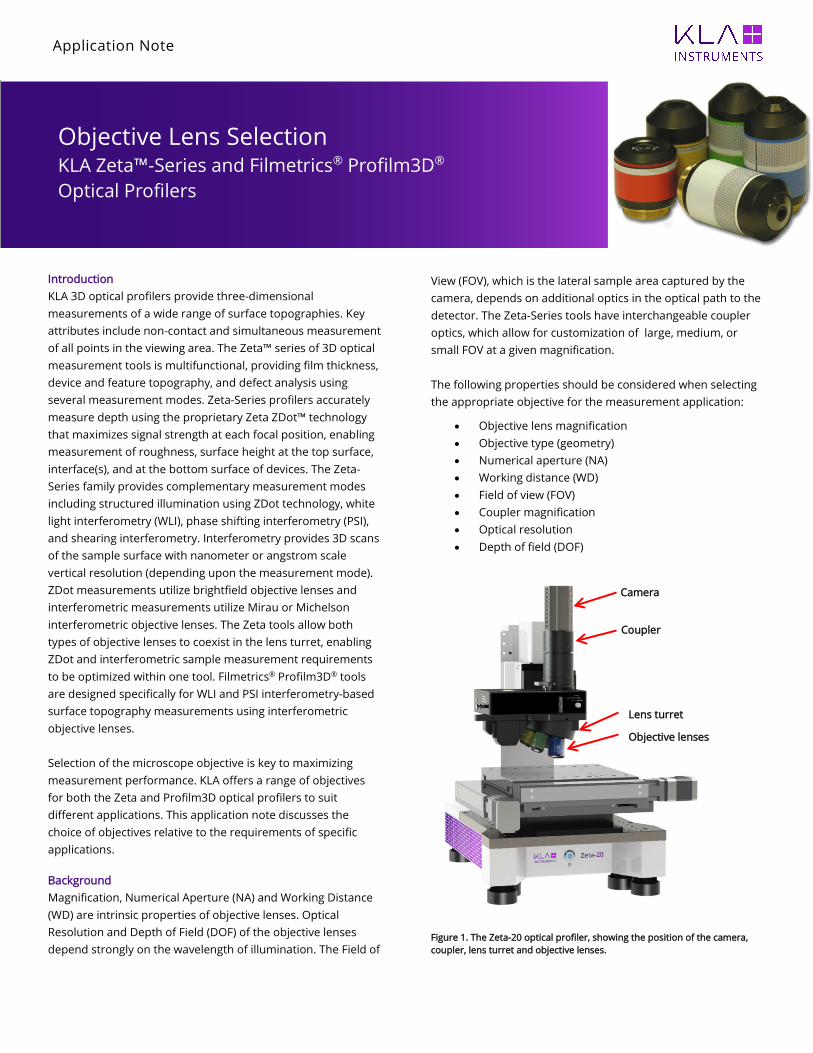
Figure 1. The Zeta-20 optical profiler, showing the position of the camera, coupler, lens turret and objective lenses.
Objective Lens Selection KLA Zeta™-Series and Filmetrics® Profilm3D® Optical Profilers
Camera
Coupler
Lens turret
Objective lenses
Application Note
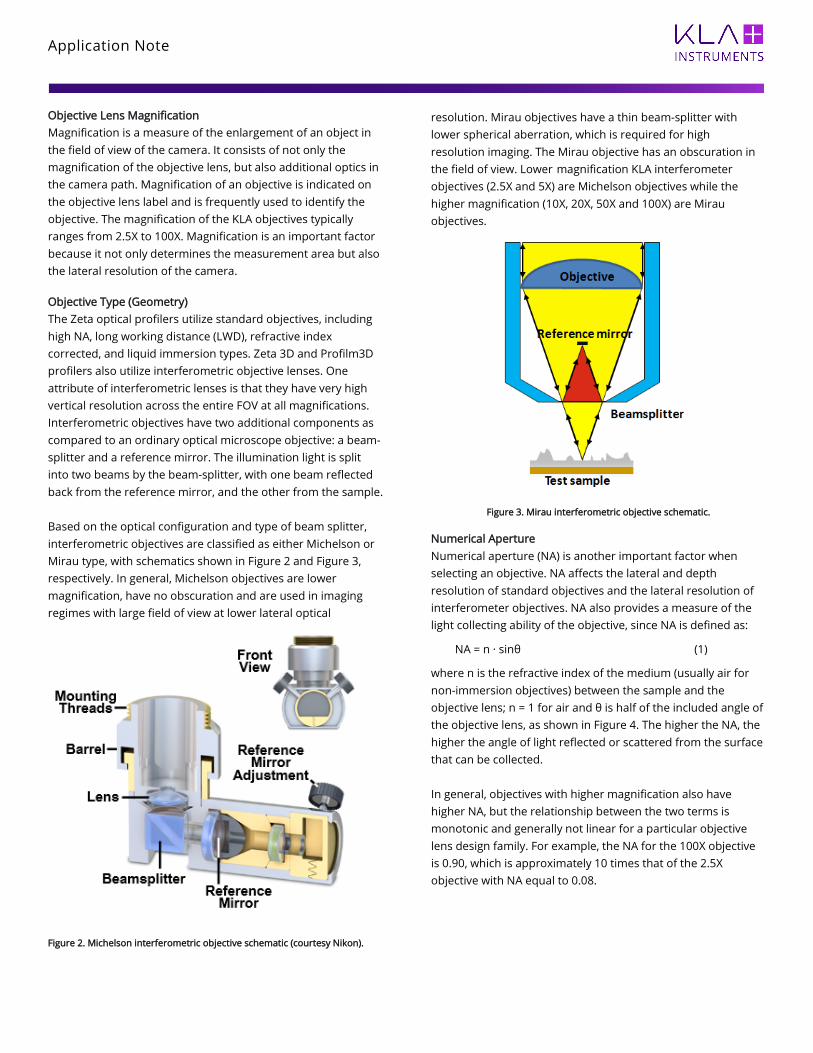
Objective Lens Magnification Magnification is a measure of the enlargement of an object in the field of view of the camera. It consists of not only the magnification of the objective lens, but also additional optics in the camera path. Magnification of an objective is indicated on the objective lens label and is frequently used to identify the objective. The magnification of the KLA objectives typically ranges from 2.5X to 100X. Magnification is an important factor because it not only determines the measurement area but also the lateral resolution of the camera. Objective Type (Geometry) The Zeta optical profilers utilize standard objectives, including high NA, long working distance (LWD), refractive index corrected, and liquid immersion types. Zeta 3D and Profilm3D profilers also utilize interferometric objective lenses. One attribute of interferometric lenses is that they have very high vertical resolution across the entire FOV at all magnifications. Interferometric objectives have two additional components as compared to an ordinary optical microscope objective: a beam-splitter and a reference mirror. The illumination light is split into two beams by the beam-splitter, with one beam reflected back from the reference mirror, and the other from the sample. Based on the optical configuration and type of beam splitter, interferometric objectives are classified as either Michelson or Mirau type, with schematics shown in Figure 2 and Figure 3, respectively. In general, Michelson objectives are lower magnification, have no obscuration and are used in imaging regimes with large field of view at lower lateral optical
Figure 2. Michelson interferometric objective schematic (courtesy Nikon).
resolution. Mirau objectives have a thin beam-splitter with lower spherical aberration, which is required for high resolution imaging. The Mirau objective has an obscuration in the field of view. Lower magnification KLA interferometer objectives (2.5X and 5X) are Michelson objectives while the higher magnification (10X, 20X, 50X and 100X) are Mirau objectives.
Figure 3. Mirau interferometric objective schematic.
Numerical Aperture Numerical aperture (NA) is another important factor when selecting an objective. NA affects the lateral and depth resolution of standard objectives and the lateral resolution of interferometer objectives. NA also provides a measure of the light collecting ability of the objective, since NA is defined as:
NA = n · sinθ (1)
where n is the refractive index of the medium (usually air for non-immersion objectives) between the sample and the objective lens; n = 1 for air and θ is half of the included angle of the objective lens, as shown in Figure 4. The higher the NA, the higher the angle of light reflected or scattered from the surface that can be collected. In general, objectives with higher magnification also have higher NA, but the relationship between the two terms is monotonic and generally not linear for a particular objective lens design family. For example, the NA for the 100X objective is 0.90, which is approximately 10 times that of the 2.5X objective with NA equal to 0.08.

Application Note
Working Distance Working distance is the distance between the bottom of the objective lens and the sample when the sample is in focus on the top surface of the sample. Working distance is indicated by dimension D in Figure 4 and varies from 2mm for the 100X objective up to 2cm for the 5X objective. For objectives with small working distances, such as 100X and 50X, it is important to pay attention to the distance between the sample and the objective to avoid crashing the objective into the sample when focusing on the sample surface.
Figure 4. Sinθ and D define the numerical aperture and working distance, respectively.
Field of View and Coupler Field of view is defined by the maximum width and length dimensions that the optical profiler can image with an objective. Although field of view is not an intrinsic property of the objective itself, it strongly depends on the specific objective that is selected. The field of view also depends on the camera and the optics of the profiler. For different profilers, the field of view may be different, even when using the same objective. However, for a given profiler, the field of view is inversely related to the magnification of the selected objective. Field of view determines the lateral extent of the captured image. Assuming the camera has N pixels along one dimension and the field of view along one axis is x microns, then the lateral pixel resolution of the camera, δc, is given by:
δc = x/N (2)
A coupler is used in the optical path after the microscope objective to help form the image on the camera by optically adjusting the effective pixel size. When using a demagnification coupler where Mc < 1.0X, the effective field of view, x’, is increased, and the effective magnification is decreased, which
changes the lateral resolution of the camera and coupler as follows:
δcc = x’/N, where x’ = x/Mc (3)
Four different coupler options are available for the Zeta 3D optical profiler to meet different application needs. The Profilm3D optical profiler uses a fixed coupler and applies a digital zoom of 1X, 2X, and 4X. At 1X, such that the entire camera field is imaged, but with reduced resolution. At 4X, 1/16 of the camera field is imaged, but at full resolution. Optical Resolution The lateral optical resolution or diffraction limited spot size is the lateral distance between two points that the objective can resolve as two distinct points. It is determined by the numerical aperture and the illumination wavelength λ. The lateral optical resolution, δ, is given approximately by:
𝛿𝛿 = 0.61𝜆𝜆/𝑁𝑁𝑁𝑁 ≈ 𝜆𝜆/2𝑁𝑁𝑁𝑁 (4)
The optical resolution calculated from Equation 4 is the optimum value the objective can achieve. When the feature dimension is smaller than δ, the image will not be able to resolve details due to the diffraction limited imaging of the optics. Instead, the feature is blurred as a circular shape with diameter δ. For example, if the optical resolution with an objective lens is 500nm when the light wavelength is 550nm, then for a triangle-shaped feature with dimension of 200nm, the feature will simply be blurred as if it were a 500nm circle. For two features separated by a lateral distance smaller than the optical resolution, the objective will have trouble identifying the individual features. With higher optical resolution objectives, 3D microscopes can capture more details of the feature of interest. This usually requires using a higher magnification objective lens, which tends to reduce the FOV. For measuring larger lateral areas with high lateral optical resolution, image stitching can be used, which is available for both Zeta 3D and Profilm3D tools. In stitching, multiple adjacent images are captured covering the full area of the region of interest and the software then combines the multiple images into one large image. Depth of Field Depth of Field (DOF) is the distance tolerance of the objective lens to achieve good focus. The microscope can still image the sample clearly when the sample is shifted slightly vertically from perfect focus, as long as the difference is smaller than the depth of field. With large depth of field, it is usually easier to find and focus on the sample. Depth of field is determined by

Application Note
the NA of the objective and the illumination light wavelength, and is given approximately by:
DOF ≈ 0.61λ/(NA2) (5)
Summary of Properties For the properties discussed above, the optical resolution (or numerical aperture) is a strict requirement for measuring small features. Field of view (or magnification) is a less strict requirement and can be compensated for by using image stitching. The working distance needs also to be considered to avoid contacting the sample surface with the objective lens, and the depth of field is mostly used to locate the sample focus plane. Measurement Examples This section shows examples of common aspects of objective lens selection for the KLA 3D optical profilers, using Apex image analysis software for generating the images.
Figure 5. The measured image of a grid with 430nm pitch with two different objectives: lower NA (top) and higher NA (bottom).
Optical Resolution When measuring very small features, the first consideration is whether the optical resolution of the objective is sufficient relative to the feature size. For example, to measure a set of features spaced equally apart on a grid with 430nm spacing, then according to Table 1, at least the 50X standard objective is required, which, with NA = 0.8, will have a resolution of 345nm; objectives with a NA < 0.64 will not be able to resolve the grid structure with good fidelity. Figure 5 shows the result of measuring the same grid with two different microscope objectives. The image from the low NA objective (top) is noisier and cannot be used to measure the lateral spacing of the grid, but the higher NA objective can clearly resolve the periodicity of the grid (bottom). Slope Measurement The profiler uses the collected reflected or scattered light from the sample to determine the height value at each lateral position. The collection ability of the optical system is dependent on the numerical aperture.
Figure 6. Schematic of measuring a sloped surface with the optical profiler. The specularly reflected light is outside the collection angle of the microscope objective.
When the optical profiler is used to measure a smooth surface with a slope, the numerical aperture of the objective needs to be large enough to capture the reflected light from the sample; otherwise, the profiler will collect only scattered light, but not the specularly reflected light from the sample, as shown in Figure 6. For a perfectly smooth sample, the maximal measurable angle of a tilted surface is θ, half of the included cone angle shown in Figure 4. In practice, surfaces have roughness, so in many cases it is possible to measure surfaces that have higher slopes than the collection angle of the

Application Note
objective lens. This is accomplished by sensing changes due to scattered light. Zeta ZDot detection is sensitive to surface roughness.
Figure 7. Interferometrically measured height data from a ball bearing using a 10X objective (top) and 20X objective (bottom).
In Figure 7, two objectives of 10X (left) and 20X (right) were used to measure the top surface of a ball bearing with a diameter of 1.59mm using interferometry. When observed from above, the slope of the ball continuously and symmetrically increases with distance from the apex point (maximum height), which is approximately at the center of the FOV of each image. The field of view from the 10X objective is ~471µm, but most of the pixels are non-measured points because the sample surface slope is too large for the objective to collect light reflected from those points. The measured area is shown in Figure 7 (top) and cropped from the original image. For the 20X objective lens, although the field of view is smaller, it has a larger numerical aperture and can measure all the
points in the smaller field of view, as shown in Figure 7 (bottom). Zeta Objective Lenses and Couplers The Zeta-Series 3D optical profilers typically use standard brightfield objective lenses for ZDot measurements. For applications involving interferometry, cover slip correction, liquid immersion, etc., additional objective lens options are available. The Zeta optical profilers can also be equipped with a diamond scribe that is mountable into the lens turret. This diamond scribe is used to mark a specific point on the sample surface to facilitate feature location for further analysis by SEM, AFM, and other analytical and sample preparation techniques. Table 1 lists the available lenses and couplers for the Zeta tools.
Table 1. Available objectives for Zeta-Series 3D optical profilers
Type Magnification Numerical Aperture
Working Distance (mm)
Standard 2.5X 0.08 10.7 Standard 5X 0.15 20.0 Standard 10X 0.3 11.0 Standard 20X 0.45 3.10 Standard 50X 0.8 1.0 Standard 100X 0.9 1.0 Standard 150X 0.9 1.0 LWD 20X 0.4 12.0
LWD 50X 0.5 10.6
LWD 100X 0.8 3.4
SLWD 50X 0.35 18.0
Glass Corrected 20X 0.45 6.4 - 7.6
Glass Corrected 40X 0.6 2.7 – 4.0
Glass Corrected 60X 0.7 1.5 – 2.2
High NA 50X 0.95 0.35
High NA 100X 0.95 0.35 Interferometer (Michelson)
5X 0.15 10.0
Interferometer (Mirau)
10X 0.3 7.4
Interferometer (Mirau)
20X 0.4 4.7
Interferometer (Mirau)
50X 0.55 3.4
Interferometer (Mirau)
100X 0.8 1.0
Liquid Immersion 20X 0.5 3.3
Liquid Immersion 60X 1.0 2.0

Application Note
Figure 8. Couplers for the Zeta profiler include the 0.35X (left), 0.5X (middle), 0.63X (right) and 1.0X (not shown).
Zeta-Series 3D optical profilers may be used with either 0.35X, 0.5X, 0.63X or 1.0X couplers, which can readily be changed by the customer to accommodate different measurement needs. The lower magnification couplers provide a larger lateral field of view and larger lateral dimensions for each camera pixel. The larger magnification couplers provide a smaller FOV, but the lateral pixel resolution is higher. Profilm3D Objective Lenses The Profilm3D optical profiler, shown in Figure 9, uses interferometric objective lenses and a camera with digital zoom. Table 2 lists the available lenses for the Profilm3D tools.
Table 2. Available objectives for Profilm3D optical profilers
Type Magnification Numerical Aperture
Working Distance (mm)
Interferometer (Michelson)
5X 0.13 9.3
Interferometer (Mirau)
10X 0.3 7.4
Interferometer (Mirau)
20X 0.4 4.7
Interferometer (Mirau)
50X 0.55 3.4
Interferometer (Mirau)
100X 0.7 2.2
Conclusion In summary, it is important to select the appropriate objective lens when using an optical profiler, with numerical aperture being a key parameter. When measuring very small features or a sample surface with large slope, the numerical aperture must be large enough so that it can resolve the features and collect enough light. Magnification is another very important parameter, because it determines the measurement area and the lateral resolution of the camera. Other objective lens parameters also need to be well understood for each specific measurement application.
Figure 9. The Filmetrics Profilm3D optical profiler, showing the position of the camera, lens turret and objective lenses.
KLA Corporation One Technology Drive Milpitas, CA 95035 Printed in the USA Rev 13 2021-07-28
KLA SUPPORT Maintaining system productivity is an integral part of KLA’s yield optimization solution. Efforts in this area include system maintenance, global supply chain management, cost reduction and obsolescence mitigation, system relocation, performance and productivity enhancements, and certified tool resale. © 2021 KLA Corporation. All brands or product names may be trademarks of their respective companies. KLA reserves the right to change the hardware and/or software specifications without notice.
Camera
Lens turret
Objective lenses