Object Oriented Design Jerry KotubaSYST39409- Object Oriented Methodologies1.
Upload
truongtuyenCategory
view
216download
2
1
Object-Oriented Design for Distributed Systems: The OSI Directory Example
Gregor v. Bochmann, St�phane Poirier and Pierre Mondain-Monval
D�partement I.R.O, Universit� de Montr�al, CP 6128, Succursale A, Montr�al, Qu�bec,Canada, H3C 3J7
Abstract
For an object-oriented design methodology to be effective, it is important to providemethods and tools for validating the design specification before going into theimplementation phase. The paper proposes a design methodology and a related object-oriented specification language which allows the validation of specifications throughsimulated execution, or through automatic exhaustive simulation for a certain subset of thelanguage. The paper also discusses the relation of this design methodology and language toother design methodologies which are in wide use, such as the entity-relationship model fordatabases, the ASN.1 notation used for Open Systems Interconnection (OSI)communication protocols, as well as methodologies used in the standardization committeesfor the elaboration and description of various kinds of distributed systems standards. It isshown how these different approaches can be integrated into a single methodology andlanguage, using the OSI Directory System as an example, which is explained in certaindetail.
1. Introduction
The goal of a design methodology is to provide simple, efficient means to structurethe process leading from an informal application description to a precise designspecification. Using an object-oriented approach, one applies the principle of aggregatingdata items together with operations performed on them, calling the whole an "object". Anapplication can be seen as a composition of such objects. One of the advantages of thisapproach is the information hiding principle, which is naturally supported. Anotheradvantage is the fact that at the informal level of description, the concept of an "object" isvery common; therefore a design and implementation framework directly supporting thisconcept leads to more readable specifications. A third important property, usuallyassociated with the object-oriented approach, is "inheritance" which, at the specificationlevel, should mean the inheritance of properties [Amer 89]. Properties defined for somemore general type of objects will be inherited by objects belonging to a more specializedtype of object, sometimes called "subclass".
Although these principles of object-oriented design are well known, it still remainsa very informal, intuitive process based on human expertise. Within a joint industry-university research project we have developed a specific methodology [Mond 90a], and arelated object-oriented specification language, MONDEL [Boch 89] which have beenapplied to a number of examples (e.g. [Mond 90]). Although our main interest has been inthe area of distributed system management and communication protocols, we believe thatour approach is general enough to be applied to many other areas.

2
For applications relating to communications and other standards, it is important toinclude, within the system design cycle, the integration of the relevant standards. Theamount of information available in these documents is generally huge, and they are mostlywritten in natural language. In the area of OSI, the standardization groups have developed acertain number of specification practices, guidelines, and more or less formal descriptiontechniques and languages (for an overview, see for instance [Boch 90b]). It is importantthat a design methodology used in this area be able to naturally integrate these existingspecification elements into the overall system description.
The purpose of this paper is to demonstrate these issues by explaining ourexperience with a particular example, namely the OSI directory system [X.500 88] . InSection 2, we give an overview of our design methodology and the MONDEL language.Section 3 describes the application of this methodology and language to the description ofthe OSI directory system. In Section 4, we discuss how our design methodology andspecification language relate to various other description techniques used for the directorystandard and in other areas. Based on these relationships, it is possible to derive certainparts of the design specification from the existing partially formalized documents.
2. Object-oriented design methodology and specification language
2.1. Design methodology
Our design methodology [Mond 90a] acknowledges the need to relate object-oriented concepts to more classical, function oriented, design practices [Ward 89] , [Bois89] . Thus our methodology uses some Entity-Relationship concepts [Chen 76] , [ISO 89]already widely applied to database and software design. In the area of distributed systems,it is also important that the design methodology relates to existing documentation, such asstandardization documents or other existing requirements. These issues are furtherdiscussed in Section 4.
Current object-oriented design methods usually comprise a certain number ofdesign steps. Though not all practitioners agree on the number and the denomination ofthese steps, they all come up with approximately the same philosophy [Booc 86] , [Meye87] , [Jalo 89] , [Bail 89]. We identified the following four major steps, which can beiterated until a satisfactory design is obtained:
1. A preliminary step first consists of the identification of the general problem area, ofthe specific aspects to be handled, and also on the aim of the expected design; thisstep is an informal one, but it should lead the designer to separate the differentaspects included in the application, and also to precisely define the intendedpurposes of the model to be elaborated.
2. Step 1: The first step of the design development consists of the identification of thekey components of the so-called application domain; this step takes as input anyinformation describing the functionalities to be provided, and should produce as aresult a set of so-called entities, together with relationships among them, which canbe easily mapped onto object-oriented languages constructs, as discussed in Section4.1.
3. Step 2: A subsequent step is concerned with the allocation of the functions asoperations offered by objects identified in the previous step; some functions willalso uncover some new objects which must be integrated in the application domain.

3
4. Step 2: The last step is concerned with the definition of the behaviors of theobjects; these behaviors consider the possible sequences of operations calls as wellas the necessary processing associated with each operation; complex objects can bespecified as smaller "applications" i.e., the entire design process can be applied toeach individual object as it is applied to the global application.
2.2. The specification language MONDEL
We have developed an object-oriented specification language called MONDEL[Boch 90l] which supports the development methodology mentioned above. In manyrespects, MONDEL resembles other existing object-oriented languages. It has, however,certain properties which make it particularly suitable for describing real-time distributedsystems, such as the example described in Section 3.
In MONDEL, everything is an object. Therefore the entities, their attributes and therelationships identified during Step 1 of the methodology are represented in MONDEL astypes, as further discussed in Section 4.1. The multiple inheritance scheme of MONDELsupports in a direct manner the "is-a" relations identified in the design.
In contrast to many other object-oriented languages, MONDEL distinguishesbetween persistent and non-persistent objects. Persistent objects are like entries in a database; they remain present until they are explicitly deleted, and they can be interrogated bydatabase-oriented statements which identify the object instances in the database whichbelong to a given class and have specified properties. Entities and relationships identifiedduring Step 1 are usually represented as persistent objects.
Concerning the design information related to Step 2 of the methodology, MONDELhas the well-known concept of operations (sometimes called "methods") which are definedfor a given object class, and are provided by each instance of that class to be called by otherobject instances. In order to call an operation, the calling object has to know the identity ofthe called object. The type checking feature of MONDEL is able to detect many designerrors related to the parameters of the called operations and the returned results.
In contrast to many object-oriented languages, communication between objects issynchronous, that is, a calling object is blocked until the called object executes a RETURNstatement, which may include the delivery of a result. Synchronous communication isbetter suited for specifications at higher level of abstraction, since cross-over of messagesat interfaces can be largely avoided [Boch 90b].
Concerning Step 3 of the methodology, MONDEL provides a number of statementsto express the order in which the operations can be accepted by an object, or for specifyingthe actions to be performed when an operation call is accepted by the object. The concept ofan ATOMIC operation is introduced which represents a "transaction" in the sense ofdatabases, that is, it represents a set of actions which are either all performed withoutinterference from other "transactions", or undone if an exception condition is encountered.The language has exception handling similar to ADA. The actions of different objects areusually performed in parallel; it is also possible to define several parallel activities within asingle object.
The statements of the language have the flavor of a high-level programminglanguage, except for the database-oriented statements mentioned above. However, it is alsopossible to write assertional specifications by defining input and output assertions foroperations, or by defining INVARIANT assertions which must be satisfied at the end each"transaction".

4
2.3. Use of specifications and related development tools
Formal, as well as informal, specifications are used in various ways. Thespecification of a system is the basis for the implementation. It is also the basis for theselection of test cases and the reference for the analysis of test results. But first of all, thespecification itself must be validated, possibly against a more abstract specification and arequirements document. In the case of protocol specifications, these issues are furtherdiscussed in [Boch 90b].
In order to partially automate the above development activities, various supporttools can be used. It is important to note, however, that specification languages without aformal definition (in particular, natural language) make the construction of automatedsupport tools very difficult. A survey of tools developed for use with protocolspecifications can be found in [Boch 87c]. Many of these tools are intended forspecifications written in one of the so-called Formal Description Techniques (FDT's). Forthe MONDEL language, a formal language syntax and semantics has been developed and isthe basis for several development tools which are shortly described below.
A MONDEL compiler verifies the syntax and static semantics of MONDELspecifications, including the type checking rules. It also translates the specification into anintermediate form which can be used for the execution by an interpreter written in Prolog[will 90] . This allows a user-guided or automatic execution of MONDEL specifications ina simulated environment which is very useful for interactively validating specifications.
While simulated executions of specifications are helpful for finding errors, they arenot able to show the absence of errors. A complementary approach of exhaustive validationmay prove the absence of errors, but is usually much more difficult to realize. Work onexhaustive validation of MONDEL specifications is in progress [barb 90d]. It is restrictedto a (useful) subset of the language and exploits the fact that this subset can be translatedinto Petri nets. The validation methods and algorithms available for Petri nets can thereforebe used on the translated specifications, or be adapted to operate directly on the MONDELspecifications.
3. An example: The OSI directory system
After an overview description of the Directory, we discuss in this section the design stepsintroduced in Section 2.1 in more detail. For each step, we first characterize the issues to beaddressed in the step in general, and then discuss the particular case of the Directoryexample. Thus we proceed through the different steps of the design methodology.
3.1. Overview of the OSI directory system
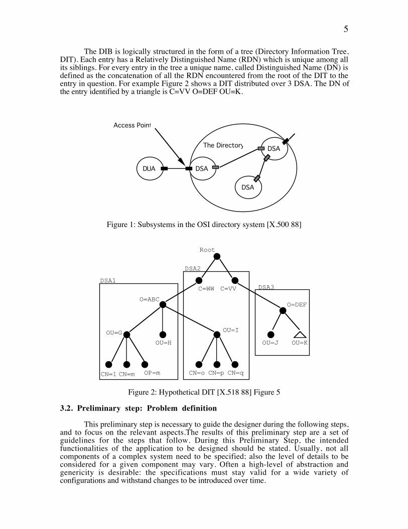
The OSI Directory system (DS) [X.500 88] is a collection of cooperating systemswhich provide information and manage a distributed database, the co-called DirectoryInformation Base (DIB). The information contained in the database is used to facilitate thecommunication with and about objects in a distributed environment, such as ApplicationEntities, people, terminals, distribution lists etc.. Although the user of the directory isunaware of it, the DIB is distributed over many sites called Directory Service Agents(DSA). The directory is accessed through user processes, called Directory User Agents(DUA), as shown in Figure 1.
The directory service is provided through a set of operation calls, which aregrouped into three service classes: The Read class allows the interrogation of theinformation contained in a particular entry of the DIB, the Search class permits theexploration of the DIB, and the Modify class permits the modification of the data in theDIB.
5
The DIB is logically structured in the form of a tree (Directory Information Tree,DIT). Each entry has a Relatively Distinguished Name (RDN) which is unique among allits siblings. For every entry in the tree a unique name, called Distinguished Name (DN) isdefined as the concatenation of all the RDN encountered from the root of the DIT to theentry in question. For example Figure 2 shows a DIT distributed over 3 DSA. The DN ofthe entry identified by a triangle is C=VV O=DEF OU=K.
DUA
Access Point
DSA
DSA
DSA
The Directory
Figure 1: Subsystems in the OSI directory system [X.500 88]
Root
DSA2
DSA1DSA3
CN=1 CN=m OP=m CN=o CN=qCN=p
OU=G
OU=H
OU=I
OU=J OU=K
O=DEFO=ABC
C=VVC=WW
Figure 2: Hypothetical DIT [X.518 88] Figure 5
3.2. Preliminary step: Problem definition
This preliminary step is necessary to guide the designer during the following steps,and to focus on the relevant aspects.The results of this preliminary step are a set ofguidelines for the steps that follow. During this Preliminary Step, the intendedfunctionalities of the application to be designed should be stated. Usually, not allcomponents of a complex system need to be specified; also the level of details to beconsidered for a given component may vary. Often a high-level of abstraction andgenericity is desirable: the specifications must stay valid for a wide variety ofconfigurations and withstand changes to be introduced over time.

6
The application to be specified may concern an existing domain. For instance,network management applications are usually defined for existing networks. Therefore, theapplication domain already exists and the new functions must cope, at the appropriateabstraction level, with existing components. Generally, the design of an application startswith a (possibly empty) given domain, and new components are to be added. Such anapproach promotes re-use of specifications since it does not isolate a given application fromexisting and future ones.
Finally, the intended purpose of the specification must be considered. Thespecification may be used for various purposes:
¥ design validation (internal consistency and relation to requirements);¥ documentation for some hardware and/or software architecture;¥ simulation, for user training, for future system development analysis, or as a
prototype before building a larger scale system;¥ performance analysis;¥ (automated) software production.
In the case of the directory system, a relatively detailed system design was alreadygiven in the form of the standard [X.518 88] . The purpose of our directory project [poir91] was to study how easy this design could be represented using the MONDEL languageand the object-oriented design methodology discussed here. We were therefore alsoconcerned with the translation of certain formalized notations used in the OSI standard intoMONDEL, as discussed in Section 4. The second purpose was to obtain an executableMONDEL specification of the directory which could be used for the validation of thedesign or as a prototype.
3.3. Design Step 1: Domain definition
The domain definition step is intended to capture the relevant elements of theexisting or foreseen domain, together with their essential characteristics. The result shouldbe a description of the domain as a set of entities together with the various relationshipsamong them that are relevant to the functionalities and purpose of the model. This step canbe decomposed into the following sub-steps:
1. The first substep is to identify entities of interest, together with their specificcharacteristics (attributes).
2. A second sub-step is to identify the various relationships existing among theseentities. They usually cover different aspects of the application to be specified, suchas:
¥ specialization of object types, represented by the inheritance relationship, oftenwritten "is-a"; different entities in the domain may share some commoncharacteristics which can be specified as a general class (or type), called"superclass", which may be inherited by more specialized subclasses
¥ structuring aspects, represented by the aggregation relationship, often stated as"is-part-of" or "is-made-of" relationships
¥ functional aspects: many identified relationships stem from the functionalitiesthe designer intends to specify

7
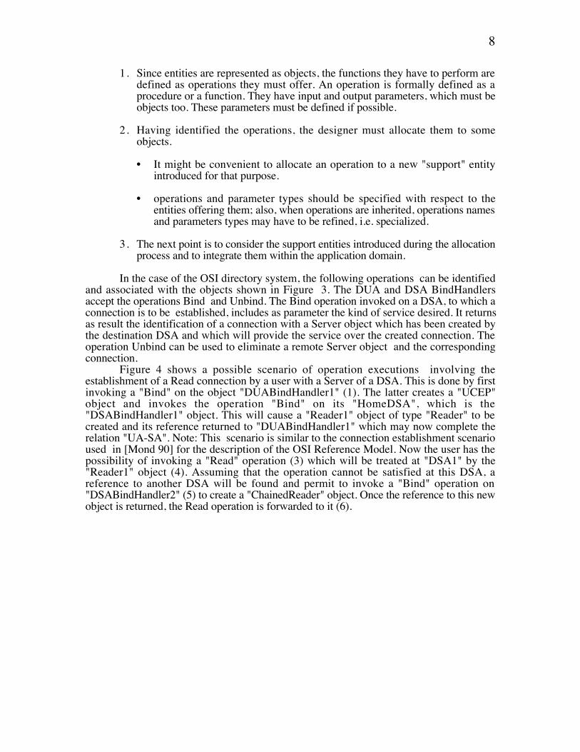
In the case of the OSI directory system, we can identify the entities and relationsshown in Figure 3, using a common graphic notation. A DSA is composed of a singleconnection handler (called Bind Handler) and a DIBFragment, and a varying number ofServer objects. A new Server object is created for each connection which is establishedwith the DSA by a DUA or another DSA. Different specializations of server objects existwhich provide the Read, Search, and Modify operations, respectively. Similarly, a DUAconsists of a single connection handler and a user connection end point (UCEP) for eachconnection established with a DSA.
DUABindHandler UCEP Server
Reader Searcher Modifier
UA-SAConnection
SA-SAConnection
DIBFragment
Bind
Unbind
DSA
Compare
Abandon
Read AddEntry
RemoveEntry
ModifyRDN
List
Search
ModifyEntry
DUAHomeDSA
DSABindHandler
Bind
Unbind
"is part of" relationship
specialization
Entity Type
operation
attribute
111
Notation
maxServer
relationship
Figure 3: Entity Relationship Diagram of the Directory System
During the domain definition, object attributes may be identified. These attributes mayrepresent specific characteristics of an object, such as the attribute "maxServer" of the typeDSA which represents the maximum number of "Server" objects that can be supported atany time. Trying to bind to a DSA once this maximum is exceeded would result in an errorcondition.
3.4. Design Step 2: Functions definition
The function allocation step intends to distribute the required functionalities amongthe identified entities. There are several important aspects to this process:
8
1. Since entities are represented as objects, the functions they have to perform aredefined as operations they must offer. An operation is formally defined as aprocedure or a function. They have input and output parameters, which must beobjects too. These parameters must be defined if possible.
2. Having identified the operations, the designer must allocate them to someobjects.
¥ It might be convenient to allocate an operation to a new "support" entityintroduced for that purpose.
¥ operations and parameter types should be specified with respect to theentities offering them; also, when operations are inherited, operations namesand parameters types may have to be refined, i.e. specialized.
3. The next point is to consider the support entities introduced during the allocationprocess and to integrate them within the application domain.
In the case of the OSI directory system, the following operations can be identifiedand associated with the objects shown in Figure 3. The DUA and DSA BindHandlersaccept the operations Bind and Unbind. The Bind operation invoked on a DSA, to which aconnection is to be established, includes as parameter the kind of service desired. It returnsas result the identification of a connection with a Server object which has been created bythe destination DSA and which will provide the service over the created connection. Theoperation Unbind can be used to eliminate a remote Server object and the correspondingconnection.
Figure 4 shows a possible scenario of operation executions involving theestablishment of a Read connection by a user with a Server of a DSA. This is done by firstinvoking a "Bind" on the object "DUABindHandler1" (1). The latter creates a "UCEP"object and invokes the operation "Bind" on its "HomeDSA", which is the"DSABindHandler1" object. This will cause a "Reader1" object of type "Reader" to becreated and its reference returned to "DUABindHandler1" which may now complete therelation "UA-SA". Note: This scenario is similar to the connection establishment scenarioused in [Mond 90] for the description of the OSI Reference Model. Now the user has thepossibility of invoking a "Read" operation (3) which will be treated at "DSA1" by the"Reader1" object (4). Assuming that the operation cannot be satisfied at this DSA, areference to another DSA will be found and permit to invoke a "Bind" operation on"DSABindHandler2" (5) to create a "ChainedReader" object. Once the reference to this newobject is returned, the Read operation is forwarded to it (6).

9
UCEP
DUA
UA-SA SA-SA
DSA1
User Reader1
Compare
Abandon
Read
DUABindHandler1DirectoryBind
DirectoryUnbind
1
2
34
5
6
DSABindHandler1DirectoryBind
DirectoryUnbind
DSA2
ChainedReader
Compare
Abandon
Read
DSABindHandler2DirectoryBind
DirectoryUnbind
HomeDSA
= operation cal
Figure 4: Object Instances in the Directory System
It is important to note that, in contrast to Figure 3 which shows the classes ofobjects in the directory system, Figure 4 shows instances of such objects and instances oftheir relations.
The Server objects accept the Read, Search or Modify operations, depending ontheir specialization. The corresponding operations of a chained Server are conceptually thesame, differing in the fact that the parameter and result types of the chained operations arerefinements of the corresponding types for the non-chained operations.
3.5. Design Step 3: Behaviors definition
This last step consists of the definition of the behaviors of the various entities forthe allocated operations. This process mainly depends on the knowledge and expertise ofthe designer in the specific field. However, some general principles can be applied:
1. For each object, it is first necessary to define the acceptable sequences ofoperations. For sequential systems, as characterized by most existing object-oriented languages, the operations are executed in the order in which they are called;in this case, any sequence would be acceptable. For concurrent systems, however,it is often important to impose ordering constraints. They may be described in asuitable formalism, such as finite state machines, Petri nets, or some concurrentspecification language, such as LOTOS [Loto 89] or MONDEL.
2. For each operation offered by a given object, there are two possibilities:
¥ the behavior for that operation is simple enough so it can be easily specifiedwith the language statements; the necessary processing is described in terms ofstate changes, attributes modifications, and interactions with other objects,which may lead to new "acquaintances".

10
¥ the behavior is complex, and a refinement process can be applied to it; thetechnique is to consider the processing to be performed as a restrictedapplication which can be specified by applying the design process fromPreliminary step to Step 3, until all components are fully specified.
In the case of the OSI directory system, we have to describe the behavior of theDUA and DSA connection handler and the different specializations of the Server class.Each operations of the Server classes is executed sequentially, as indicated in Figure 5. Theoperation dispatcher and name resolution procedure are the same for all classes, while theevaluation procedure depends on the operation.
Operation Dispatcher
Name Resolution Evaluation Results Merging
DSA
FindNamingContext
LocalName
Resolution
Figure 5: DSA Behavior - Internal View [X.518 88] Figure 10
The first phase of the execution consist of finding a target object in the DIT fromwhich the evaluation will proceed. This search for the target object may traverse more thanone DSA and is done by the NameResolution operation. It may involve forwarding therequest to several remote DSA's in parallel. The NameResolution is subdivided into twosubtasks: (1) FindNamingContext looks for a matching subtree of the DIT , which is calledthe NamingContext. The LocalNameResolution traverses the identified subtree . Theevaluation phase depends on the operation invoked. In the case of a subsequent simpleRead operation, for instance, all the information required is contained in the current DSA.In the case of more complex inquiries the evaluation might require information contained inother DSA; in such case, the merging phase is required. The Dispatcher procedure controlsthe sequential ordering of these phases for the various Directory operations. Its operation isillustrated in the standard [X.518 88] by a flow chart which, however, does not show thedistribution of these actions over the different DSA's.
The NameResolution procedure returns either a reference to some entry contained inthe DIBFragment, if the target is found locally, or a reference to another DSA, if the entryis not found locally. We therefore must introduce the concept of a DSA reference whichleads to an iteration of the design steps, and a more detailed design as discussed in thefollowing subsection.
3.6. Additional object types in relation with the behavior definition
When the local DIBfragment does not contain the entry which is required, the DSAmust be able to identify another DSA that should be able to supply additional information.To this end, a DSA must contain a set of references to other DSA.

11
The different types of references that may exist are the following:
- Superior reference : reference to the DSA which contains Directory informationimmediately superior, within the global DIT, to the information contained in the currentDSA.
- Non specific subordinate reference (NSSR) : The referred DSA is known to containinformation which is subordinate. The exact nature of the information is unknown.
- Cross reference : The purpose of this type of reference is to accelerate a search. It refersto information not related to the local DIB fragment.
The DIT structure is represented by the Node entity type and a recursive "Parent"relation, as shown in Figure 6. The DIBFragment of the DSA contains one or more so-called naming contexts which are subtrees of the DIT structure. For example DSA2 inFigure 2 has three Naming contexts which are identified by their respective context prefixesC=WW, C=VV and C=WW O=ABC OU=I. A node of the subtree is either the root node,a data node or a specific subordinate reference node. A data or root node is actual data inthe DIB. A reference node contains what is called a subordinate reference, which is areference to a DSA which contains the naming context equivalent to the DN of that node. InFigure 2 each edge which leads from one DSA to another DSA represents a subordinatereference.
For the execution of the NameResolution procedure in the distributed context, weneed to find the naming context whose prefix most closely matches the DN of the entry weare looking for. This is done by the internal procedure "FindNamingContext" shown inFigure 6. Similarly, the procedure "FindCrossRef" finds the closest match among theavailable cross references. Once we have found a matching naming context we must thensearch the nodes of the subtree for an entry which will satisfy the query or for asubordinate reference. This is done recursively by the operation "NodeSearch" associatedwith each Node of the DIT (see Figure 6).

12
NameResolution
SuperiorRefCrossRef NSSRef
DIBFragment
FindNamingContext
RootNode
ContextPrefix
DataNode
Entry
Node
RDN
ReferenceNode
SubordinateRef
ParentNodeSearch
1
FindCrossRef
Figure 6: Information Held in a DSA
This discussion completes the design for the behavior of the operations provided by theDIBFragment object. It is an example of a recursive refinement process which introducesnew object types, and therefore to the related design steps 2 and 3 for these objects. In thisexample, this process stops after one iteration.
Because of space limitations, only certain aspects of our Directory design [poir 91]could bedescibed here. The annex contains a listing of a complete MONDEL specification of asimplified Directory system.
4. Discussion of various description formalisms
For applications, such as the directory system discussed in this paper, where manystandards and other documents must be considered during the system design, it isimportant to find a common description formalism which is suitable to express all relevantdesign issues, is close to the formalism used in the standard and other documents, andformal enough to allow computer-aided design tools. We have tried to make MONDELcompatible with several notations used in the context of OSI standardization and otherareas, such as explained in the following subsections (see [Boch 90z] for further details).
13
4.1. The entity-relational model and object-oriented specifications
We discuss in this subsection how the concepts of the entity-relationship (ER)approach [Chen 76] relates to the object-oriented approach, and how these concepts can berepresented using the MONDEL specification language. It is assumed that the reader isfamiliar with the ER approach.
4.1.1. Classes, objects and inheritance
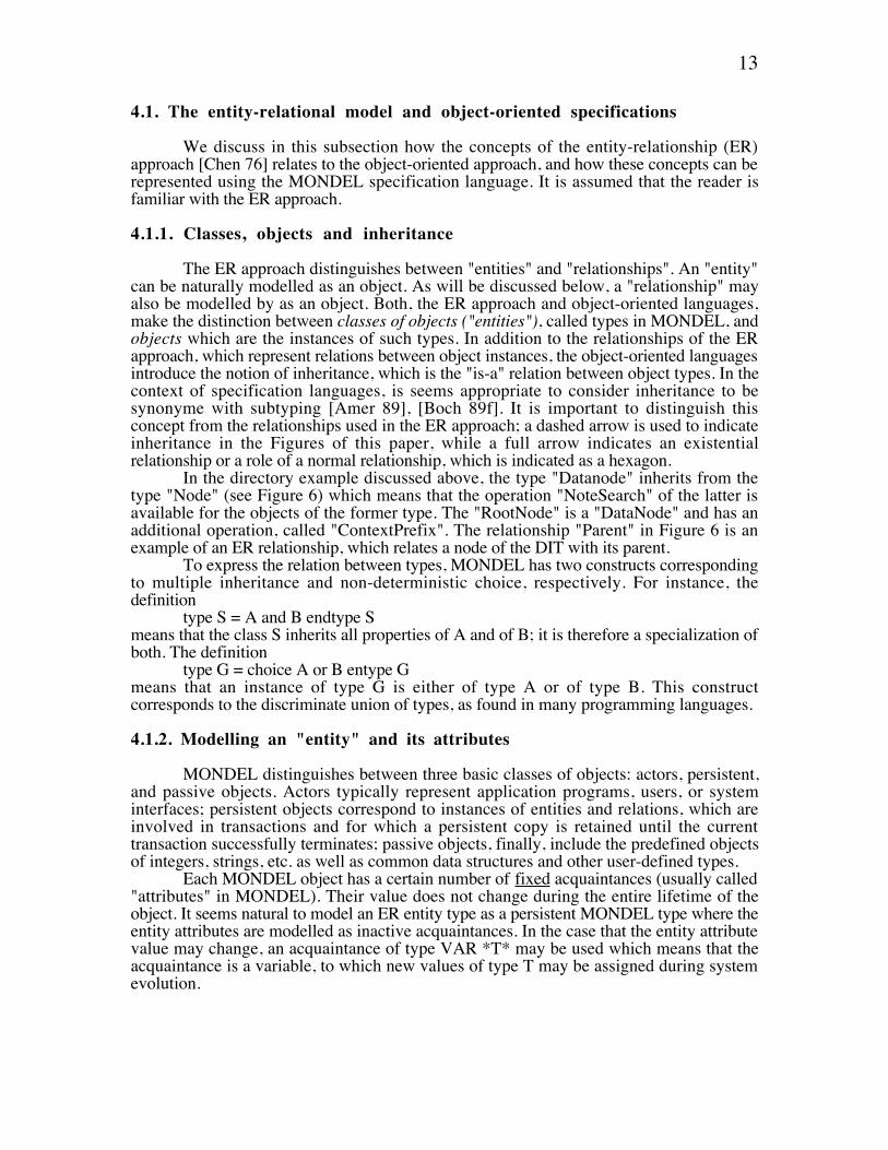
The ER approach distinguishes between "entities" and "relationships". An "entity"can be naturally modelled as an object. As will be discussed below, a "relationship" mayalso be modelled by as an object. Both, the ER approach and object-oriented languages,make the distinction between classes of objects ("entities"), called types in MONDEL, andobjects which are the instances of such types. In addition to the relationships of the ERapproach, which represent relations between object instances, the object-oriented languagesintroduce the notion of inheritance, which is the "is-a" relation between object types. In thecontext of specification languages, is seems appropriate to consider inheritance to besynonyme with subtyping [Amer 89], [Boch 89f]. It is important to distinguish thisconcept from the relationships used in the ER approach; a dashed arrow is used to indicateinheritance in the Figures of this paper, while a full arrow indicates an existentialrelationship or a role of a normal relationship, which is indicated as a hexagon.
In the directory example discussed above, the type "Datanode" inherits from thetype "Node" (see Figure 6) which means that the operation "NoteSearch" of the latter isavailable for the objects of the former type. The "RootNode" is a "DataNode" and has anadditional operation, called "ContextPrefix". The relationship "Parent" in Figure 6 is anexample of an ER relationship, which relates a node of the DIT with its parent.
To express the relation between types, MONDEL has two constructs correspondingto multiple inheritance and non-deterministic choice, respectively. For instance, thedefinition
type S = A and B endtype Smeans that the class S inherits all properties of A and of B; it is therefore a specialization ofboth. The definition
type G = choice A or B entype Gmeans that an instance of type G is either of type A or of type B. This constructcorresponds to the discriminate union of types, as found in many programming languages.
4.1.2. Modelling an "entity" and its attributes
MONDEL distinguishes between three basic classes of objects: actors, persistent,and passive objects. Actors typically represent application programs, users, or systeminterfaces; persistent objects correspond to instances of entities and relations, which areinvolved in transactions and for which a persistent copy is retained until the currenttransaction successfully terminates; passive objects, finally, include the predefined objectsof integers, strings, etc. as well as common data structures and other user-defined types.
Each MONDEL object has a certain number of fixed acquaintances (usually called"attributes" in MONDEL). Their value does not change during the entire lifetime of theobject. It seems natural to model an ER entity type as a persistent MONDEL type where theentity attributes are modelled as inactive acquaintances. In the case that the entity attributevalue may change, an acquaintance of type VAR *T* may be used which means that theacquaintance is a variable, to which new values of type T may be assigned during systemevolution.

14
For example, the following definitiontype RootNode = DataNode with
contextPrefix : contextPrefixendtype RootNode
describes the entity "RootNode" of Figure 6. "contextPrefix" is its specific attribute, it alsoinherits the attributes "Entry" and "RDN" from its superclasses.
4.1.3. Modelling relationships using the "database approach"
A relationship between object instances can be directly modelled in MONDEL as anobject type which has an acquaintance for each role of the relation. For instance, thedefinition
type UA-SA = persistent with ucep : UCEP server : Serverendtype UA-SA
describes a relationship between the "UCEP" and "Server" types of Figure 3.
This approach of modelling relationships has the following properties:
(1) Referential integrity (i): An instance of a relationship can not be created without theexistence of the related entity instances.
(2) Referential integrity (ii): If one of the related entities is deleted, the correspondinginstance(s) of a relationship is (are) also deleted.
(3) Dynamic relationship: The creation and deletion of instances of a relationship donot affect the existence of the related entities.
(4) Independence: The relationship and the related entities are specified as separatetypes.
(5) Specialization and relationship attributes: A basic relationship (as exemplifiedabove) may be refined by adding attributes or other pertinent information to thedefinition of the relation type. For instance, it is possible to specify furtherproperties by defining a subset of the acquaintances to form a key, or by adding aninvariant condition which must be satisfied during the creation of each occurrenceof the type. An example is shown in Section 4.1.5 below.
4.1.4. Modelling relationships using the "data structure approach"
In the context of high-level programming languages, relationships may berepresented using various data structures. MONDEL provides certain predefined structures,such as VAR, SET, BAG, and SEQUENCE, which may be used for this purpose.However, the symmetry between the different roles of the relationship is lost in theserepresentations.
For example, the first relationship "is part of" in Figure 6 could be represented byan acquaintance (of the DIBFragment) which is of type SET *CrossRef*, which means thata zero or more cross references, in no particular order, may be contained in a DIBFragment. With this approach, the aspects (2), (4) and (5) of Section 4.1.3 are lost. In the case thatat most one reference exists for each instance of DIBFragment, the acquaintance may be oftype VAR *CrossRef*, instead of a SET *CrossRef*, which simplifies its use andimplementation; the value NIL can be used to indicate the absense of a related reference.The same representation may be used for entity attributes.

15
In the above cases, the "is-part-of" relationship was represented by an acquaintanceof the composed object. Inversely, if the "is part of" relationship is fixed for eachcomponent, the relationship may be represented by a fixed acquaintance of the component.For example, the above relationship could be represented by an acquaintance (of the"CrossRef" entity) which is of type "DIBFragment". In MONDEL, this representation alsoimplies referencial integrity, that is, if a "DIBFragment" is deleted then all "CrossRef",related to it, will also be deleted.
4.1.5. Modelling aggregation relationships
An aggregation relationship, such as "an entity instance of type AType is composedof entities of type BType", is a particular case of a functional relation from BType toAType, and can be modelled as explained above. For example, the relation that a "Node" ofthe DIB may be (recursively) composed of several subnodes may be described as
type Node = persistent with superior : Node OPT; {or "superior : VAR*Node* ;" }endtype Node
The superior acquaintance assumes the value NIL if the Node instance is the rootnode. This condition may be formalized by the use of the MONDEL invariant clause asfollows:
type RootNode = DataNode with contextPrefix : DistinguishedName invariant
superior = nilendtype RootNode
4.2. Standard data structure definitions in ASN.1
This notation is used mainly for the definition of the messages exchanged betweenapplication protocol entities of systems following the OSI communication standards.However, it could also be used for other purposes. The notation [ASN1 ] allows thedefinition of data types, similar to the data type definitions available in programminglanguages such as Pascal or ADA. The notation includes a number of predefined types suchas integers, reals, booleans, bit strings etc ... It also allows the definition of composedtypes, such as groups of elements (called SEQUENCE, corresponding to the PascalRECORD), lists of elements of the same type (called SEQUENCE OF), a list of alternativetypes (called CHOICE, corresponding to Pascal's variant records) etc... An associatedcoding/decoding scheme [ASN1 C] defines the data transmission format forcommunication between different OSI systems.
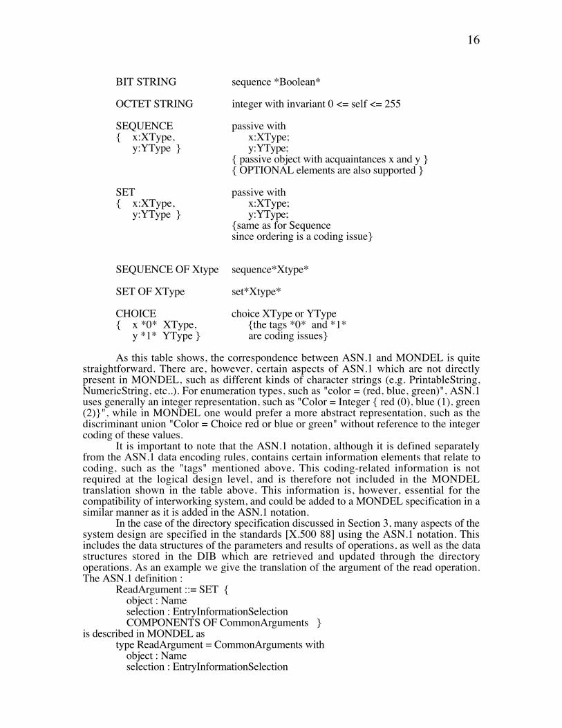
The predefined data types and structuring facilities defined in ASN.1 are similar towhat can be found in many programming and specification languages. Some systematictranslations from ASN.1 to data structures in specification languages, such as Estelle andLOTOS, or implementation languages, such a C (see for instance [Boch 89h]) have beendefined. A similar translation can be defined into MONDEL, as shown in the table below:
ASN.1 types MONDEL types ��
INTEGER integer
BOOLEAN boolean
NULL none {the only value is NIL}
ANY object {the most general type of object}
16
BIT STRING sequence *Boolean*
OCTET STRING integer with invariant 0 <= self <= 255
SEQUENCE passive with{ x:XType, x:XType;
y:YType } y:YType;{ passive object with acquaintances x and y }{ OPTIONAL elements are also supported }
SET passive with{ x:XType, x:XType;
y:YType } y:YType;{same as for Sequencesince ordering is a coding issue}
SEQUENCE OF Xtype sequence*Xtype*
SET OF XType set*Xtype*
CHOICE choice XType or YType{ x *0* XType, {the tags *0* and *1*
y *1* YType } are coding issues}
As this table shows, the correspondence between ASN.1 and MONDEL is quitestraightforward. There are, however, certain aspects of ASN.1 which are not directlypresent in MONDEL, such as different kinds of character strings (e.g. PrintableString,NumericString, etc..). For enumeration types, such as "color = (red, blue, green)", ASN.1uses generally an integer representation, such as "Color = Integer { red (0), blue (1), green(2)}", while in MONDEL one would prefer a more abstract representation, such as thediscriminant union "Color = Choice red or blue or green" without reference to the integercoding of these values.
It is important to note that the ASN.1 notation, although it is defined separatelyfrom the ASN.1 data encoding rules, contains certain information elements that relate tocoding, such as the "tags" mentioned above. This coding-related information is notrequired at the logical design level, and is therefore not included in the MONDELtranslation shown in the table above. This information is, however, essential for thecompatibility of interworking system, and could be added to a MONDEL specification in asimilar manner as it is added in the ASN.1 notation.
In the case of the directory specification discussed in Section 3, many aspects of thesystem design are specified in the standards [X.500 88] using the ASN.1 notation. Thisincludes the data structures of the parameters and results of operations, as well as the datastructures stored in the DIB which are retrieved and updated through the directoryoperations. As an example we give the translation of the argument of the read operation.The ASN.1 definition :
ReadArgument ::= SET { object : Name selection : EntryInformationSelection COMPONENTS OF CommonArguments }is described in MONDEL as
type ReadArgument = CommonArguments with object : Name selection : EntryInformationSelection

17
endtype ReadArgument;The ASN.1 notation COMPONENTS OF has the meaning of "includes the elements of anamed SET (CommmonArguments). This is equivalent to these inheritance of theattributes; hence the MONDEL notation above.
4.3. Remote Operations and other object-oriented notations
Various extensions to ASN.1 have been developed within the OSI standardizationcommunity for describing such issues as:
(a) "Remote Operations" [OSI RO] which correspond to the well-known concept ofremote procedure calls,
(b) ports through which application layer service connections can be defined [X.407 ] ;and
(c) object classes with attribute and inheritance relations [ISO 89].The latter notation supports concepts similar to those discussed here (see [Boch 90z] for amore detailed comparison). However, it is not used for the description of the OSI directorystandard. The ports described in the directory standard [X.500 88] have been representedin our object-oriented description in the form of objects. That is, the concepts of port andconsumer or supplier of an operation have been joined into a single type. For example, the"Server" type is called upon to act as both supplier port and supplier of the operation.
A "remote operation" can be modelled naturally in MONDEL in the form of anoperation call. In MONDEL, as in any object-oriented language, all communicationbetween objects proceeds through the call of operations. An operation is associated with anobject, which must be known to the object that executes the call. In MONDEL, the callingobject has to wait for the return of the operation, which may include the result of theoperation, or may occur immediately after the acceptance of the operation by the calledobject. This allows the modelling, in MONDEL, of the synchronous and asynchronouscommunication foreseen for "remote operations" (see [Boch 90z] for more details).
An example is shown below in the form of the Read of the OSI Directory which is asynchronous remote operation. The example makes use of MONDEL exception handling: ifduring the execution of the Read, the Reader encounters an error situation, a RAISEstatement will automatically return an exceptional result to the calling procedure.The X.500definition, using the ROSE notation [OSI RO]Read ::= ABSTRACT-OPERATION
ARGUMENT ReadArgumentRESULT ReadResultERROR {Referal,AttributeError,NameError,ServiceError}
may be represented by the MONDEL operation declaration below(using explicit declarationof exceptions as in Modula 3 [Card 88b] )
type Reader = Server with
operation Read (ReadArgument) : ReadResult raises Referal,AttributeError, NameError, ServiceError ;
behavior accept r : Read {operation treated as an object, not supported by [Boch 90l]}
return dispatch(r); end; {accept}
endtype Reader

18
We have included above the behavior definition of the "Read" operation and thetype definition that supports this operation. The dispatch function is the same for allServers (Readers, Searchers and Modifiers, see Figure 3) and is detailed in the nextsection. The Read operation could be called from a UCEP object through the execution ofthe following statement. ... try result := reader!Read(readArg); except of type AttributeError => ... {error handling} type NameError => ... {error handling} type ServiceError => ... {error handling} end { try }
4.4. The description of object behavior
For the description of the behavior of operations, one may use algorithmicspecifications based on a high-level programming language (an approach taken forMONDEL) or based on graphic notations, such as Nassy-Shneiderman diagrams. In analternate approach, the specifier defines input and output assertions for the operations.These approaches are sufficient in the case of "sequential" objects, that is, for objects thataccept one operation call after another, in an arbitrary order.
In the context of distributed systems, however, the order of execution of differentoperations is often of prime importance. In order to specify the allowed sequences ofoperation executions, there are a number of approaches, varying between algorithmicspecifications (e.g. LOTOS [Loto 89] or MONDEL) defining directly the possibleexecution orders, and assertional methods imposing constraints on the allowed executionsequences and their parameters (e.g. [Hoff 88] ).
A finite state machine (FSM) model is often used for the specification of orderingconstraints for communication protocols and other applications, however, it usually onlyprovides for a simplified model of the specified system. This model is directly supportedby certain description techniques (e.g. Estelle [Este 89] and SDL [SDL 87] ), and can alsobe translated in a straightforward manner into an algorithmic form. One translation schemeforesees one procedure per state; it models the FSM in a direct manner. Another translationscheme tries to obtain an algorithmic description which follows, as much as possible, thestyle of structured programming [Boch 87g] .
All these approaches are characterized by the fact that a single FSM is representedby a single object instance. Analogous translation schemes also exist for Petri nets.However, in this case a single Petri net gives rise to several objects; in one case [barb 90d],each token of the Petri net corresponds to an object in the object-oriented description.
In the case of the directory system, the behavior of the objects are essentiallysequential. They execute one operation after the other. This simplifies the specification. Thestandard provides a few flowcharts which define the actions which must be performed forthe execution of an operation. However, this description does not take explicitly intoaccount the fact that some of these actions may have to be performed in a distributedfashion. For writing an object-oriented specification, it is therefore necessary to explicitlydistribute these actions over the different objects involved. The resulting specification forthe dispatch function is shown here as an example.
type Server = persistent with part_of : DSA hide fragment : DIBFragment {the DIBFragment of the DSA}where
function dispatch(op:ServerOperation) : ResultType raises Referal =

19
case result = fragment!NameResolution(op) of
type Entry => { entry found in this DSA} return Evaluation(op,result);
{evaluation depends on specialization of the server type, eg: Reader }
type Reference=> {this will trap all references, i.e. the target entry is not in this DSA} if op.arg.InteractionModeIsChain = false
then Raise(new Referal(result)) {sending an error message including a reference } else { loop avoidance } op.arg.traceInformation!updateTraceInfo;
{Set up an chained association with a DSA} define server = result.remoteDSA!Bind(Selftype,new BindArgument()).server in server!op {Send the operation call to the next server}
{ no compile type checking } end; {define} end; { if } end; { do case }
endproc dispatcherendtype Server
It is to be noted that the dispatch function above is used by all operations of adirectory "Server" object (reading, searching, modifying). The function first calls theNameResolution function which attempts to find a match, within the DIBFragment of thecurrent DSA, for the target RDN of the operation. If a match is found (case "Entry"), theentry is passed to the "Evaluation" function (which represents the evaluation phasementioned in Section 3.5), which is defined in each "Server" subclass, since it is particularclass of operation. In the case that not an entry, but a reference is found (case "Reference"),the dispatch function establishes a connection with the DSA identified by the reference andchains the operation to this DSA where the previous steps are repeated.
5. Conclusions
We have presented in this paper an object-oriented design and formal specificationof the OSI Directory System. This specification was developed using an object-orienteddesign methodology and related specification language, called MONDEL. Since the OSIDirectory standard includes already most of the design choices included in ourspecification, the main interest of this work is to demonstrate how various different designparadigms and description techniques can be integrated into an object-oriented approachand supported by a single object-oriented specification language.
Most of these paradigms and description techniques address one of the following aspects:
(a) The identification of entity types and relationships within the application domain, at anearly phase within the design process. This is related closely to the entity-relationshipmodel for databases, and some description standards and design methodologies fordistributed systems [ODP 88].
(b) Specialization of object classes, a concept called inheritance in many object-orientedlanguages.

20
(c) The description of operations that may be invoked on objects, and of data structuresthat may be used as parameters or result types. This relates to the ASN.1 notation usedin the OSI standardization context, and corresponding notations used in manyprogramming languages.
(d) The description of the behavior of objects, which should determine the effect andresults of operations and any constraints on the order and/or parameter values ofoperation invokations. This relates to various description paradigms, such as finite statemachines (or extensions, such as SDL or Estelle), structured programming notationsand flowcharts (such as Nassy-Sheiderman), or assertional methods using input/outputassertions. This aspect is the most difficult one for any system description.
The integration of these different aspects into a single design methodology,supported by a suitable specification language, and associated with suitable tools for thevalidation of design specifications, the development of implementations from the design,and the generation and management of appropriate test cases, is clearly a desirable goal.However, it is not clear how best to develop an overall system/application developmentenvironment which makes the development process more efficient and reliable. We thinkthat the here described example of the OSI Directory System demonstrates that the first partof the goal, namely the integration of existing design paradigms and description techniquesinto a single object-oriented methodology and specification language, may be feasable.
Acknowledgements
The here described methodology and specification language was developed within ajoint research project on "Object-oriented databases: application modelling and specifcationfor telecommunications network management" by Bell-Northern-Research and theComputer Research Institute of Montreal (CRIM). The authors thank all members of thisresearch group for many fruitful discussions. The work on the Directory System wassupported by the IDACOM-NSERC-CWARC Industrial Research Chair onCommunication Protocols at the Universit� de Montr�al.

21
References
[Amer 89] P. America, A behavioural approach to subtyping in object-orientedprogramming languages, Philips J. Res. (Netherlands), Vol. 44, Nos. 2-3,pp.365-383, 1989.
[Bail 89] S. C. Bailin, An object-oriented requirements specification method,Communication of the ACM, Vol. 32, No. 5, May 1989. Proceedings of thefifth Washington Ada Symposium, June 1988. Report Document N 11 forCRIM/BNR project, June 1990.
[barb 90d] M. Barbeau and G. v. Bochmann, Formal Verification of Object-OrientedSpecifications in Mondel Using a Coloured Petri Net Based Technique,submitted for publication.
[Boch 89] G. Bochmann and e. al., The specification language Mondel, CRIM/BNRProject.
[Boch 87c] G. v. Bochmann, Usage of protocol development tools: the results of asurvey, (invited paper), 7-th IFIP Symposium on Protocol Specification,Testing and Verification, Zurich, May 1987, pp.139-161.
[Boch 89f] G. v. Bochmann, Inheritance for objects with concurrency, submitted forpubl.
[Boch 90z] G. v. Bochmann and e. al., System specification with MONDEL and relationwith other formalisms, Progress Report No. 13 for CRIM/BNR project, June1990.
[Boch 90l] G. v. Bochmann, M. Barbeau, M. Erradi, L. Lecomte, P. Mondain-Monvaland N. Williams, Mondel: An Object-Oriented Specification Language,submitted for publication.
[Boch 89h] G. v. Bochmann and M. Deslauriers, Combining ASN1 support with theLOTOS language, Proc. IFIP Symp. on Protocol Specification, Testing andVerification IX, June 1989, North Holland Publ., pp.175-186.
[Boch 90b] G. v. Bochmann and P. Mondain-Monval, Design Principles forcommunication gateways, IEEE Tr. on Selected Areas in Communications,Vol.8, 1 (Jan. 1990), pp. 12-21.
[Boch 87g] G. v. Bochmann and J. P. Verjus, Some comments on, transition-oriented"vs. "structured" specification of distributed algorithms and protocols", IEEETrans. on SE Vol SE-13, No 4, April 1987, pp. 501-505.
[Bois 89] H. Bois, Une m�thode de d�veloppement de logiciels fond�e sur le conceptd'objet et exploitant le langage ADA Universit� Paul Sabatier, ToulouseFrance, October 1989,
[Booc 86] G. Booch, Object-oriented development, IEEE Transactions on SoftwareEngineering, February 1986.
[Card 88b] L. Cardelli, J. Donahue, L. Glassman, M. Jordan, B. Kalsow and G.Nelson, Modula 3 Report, DEC, 1988.
[X.407 CCITT, X.407 / ISO 8505-4, Message Handling Systems Abstract Servicedefintion Conventions, 1988.
[Chen 76] P. P. Chen, The Entity-Relationship model - Toward a unified view of data,ACM Trans. on Database Systems, Vol. 1, No. 1, March 1976, pp.9-36.
[Hoff 88] D. Hoffman and R. Snodgrass, Trace specifications: Methodology andmodels, IEEE Tr. SE 14, No. 9 (Sept. 1988), pp. 1243-1252.
[ISO 89] ISO, DIS 9595 Common Management Information Service Definition, 1989,[Loto 89] ISO, IS8807 (1989), LOTOS: a formal description technique,[Este 89] ISO, IS9074 (1989), Estelle: A formal description technique based on an
extended state transition model,[ASN1 C] I. 8. ISO, Information Processing - Open systems Interconnection - Basic
Encoding Rules for Abstract Syntax Notation One (ASN.1),[OSI RO] I. 9. ISO, Remote Operations, IS 9072.

22
[Jalo 89] P. Jalotte, Functional refienement and nested objects for object-orienteddesign, IEEE Transactions on Software Engineering, Vol. 15, no. 3,March1989.
[Meye 87] B. Meyer, Reusability: the case for object-oriented design, IEEE Software,March 1987.
[Mond 90a] P. Mondain-Monval, An object-oriented software design methodology,Progress Report Document no.7 for CRIM/BNR project, June 1990.
[Mond 90] P. Mondain-Monval and G. v. Bochmann, Object-oriented Model for the OSIReference Model, submitted for publication.
[ODP 88] ODP, Modeling techniques and their use in ODP ISO/IEC JTC1/SC21 N3196, Working Document on Topiic 6.1, December 1988.
[poir 91] S. Poirier, �valuation du langage de sp�cification Mondel � la description deprotocoles de communication, MSc thesis, Universit� de Montr�al, enpr�paration.
[SDL 87] SDL, CCITT SG XI, Recommendation Z.100, 1987,[Ward 89] P. T. Ward, How to integrate Object-oriented with structured analysis and
design, IEEE Software, March 1989.[will 90] N. Williams, Un simulateur pour un langage de sp�cification orient�-objet,
MSc thesis, Universit� de Montr�al.[X.500 88] X.500, CCITT, ISO 9594 The Directory - Overview of concepts, Models and
Services, 88,[X.518 88] X.518, CCITT, ISO 9594-4 The Directory - Procedures for Distributed
Operation, 1988,

23
Annex
This annex is an incomplete specification of the directory in MONDEL. It includes thoseaspects of the directory that are discussed in Sections 3.3 through 3.5 in the paper. It isstructured according to the three design steps. The type definitions in the design steps 2and 3 are refinements of the corresponding definitions in the steps 1 and 2, respectively.
Design Step 1 :
unit DesignStep1 use predefined
type DUA1 = object withhomeDSA : DSA
duaBindHandler : DUABindHandlerucep : UCEP
endtype DUA1
type DUABindHandler1 = objectendtype DUABindHandler1
type UCEP1 = object withremote : Server1
endtype UCEP
type Server1= objectremote : Server1
endtype Server1
type DSA1 = object withdIBFragment : DIBFragment
server : Server1dsaBindHandler : DSABindHandler
maxServer : Integerendtype DSA1
type DSABindHandler1 = objectendtype DSABindHandler1
endunit DesignStep1
Desing Step 2:
unit DesignStep2 use DesignStep1
type DUABindHandler2 = DUABindHandler1 withoperations
Bind(DirectoryBindArgument):DirectoryBindResultUnbind:(DirectoryUnBindArgument)
endtype DUABindHandler2
type Reader2 = Server1 withoperation
Read(ReadArgument):ReadResult; raises Referal, AttributeError, NameError, ServiceError;
Compare(CompareArgument):CompareResult; raises Referal, AttributeError, NameError, ServiceError;
Abandon(AbandonArgument):AbandonResult; raises Referal, AttributeError, NameError, ServiceError;endtype Reader2
type DSABindHandler2 = DSABindHandler1 withoperations
Bind(ServerType,DirectoryBindArgument) : DirectoryBindResult;Unbind(Server1);

24
endtype DSABindHandler2
endunit DesignStep2
Design Step 3 :
unit DesignStep3 use DesignStep2
type DUABindHandler3 = DUABindHandler2 withbehavior loop accept Bind(dirBindArg:DirBindArg) do define ucep := EstablishAssociation(dirBindArg.serverType); in return (new DirBindResult(ucep)); end; or Unbind(ucep) do DestroyAssociation(ucep); return; end; end; { accept } end; { loop }
where
procedure EstablishAssociation(serverType : Type):UCEP=
{ Requesting the creation of a distant server }
try dirBindResult := dSAHandler!DirectoryBind(serverType,dirBindArg); except DirectoryBindError(directoryBindError); { connection refused } do raise (new DirectoryBindError()); end;end { try }
{ connection accepted }define ucep = new UCEP; {Creating a local connection end point } in ucep.remote = dirBindResult.remoteServer
{associating distant server with local ucep } return ucep;end; {define }endproc EstablishAssociation;
procedure DestroyAssociation(ucep : UCEP1) = dSAHandler!Unbind(ucep.remote); {send Unbind to DSA} ucep!dispose; { this connection is closed }endproc DestroyAssociation;
endtype DUABindHandler3
type DSABindHandler = DSA2 with
behavior
loop accept Bind(dirBindArg:DirBindArg): DirBindResult do

25
define server = new dirBindArg.serverType in return (dirBindResult(server)); end; { define} end;
or Unbind(server) do DestroyAssociation(server); return; end;
end; { accept }
end; { loop }
where
proccedure DestroyAssociation(server : Server1) =
if server.remote <> nil then server.dSAHandler!Unbind(server.remote); { The operation has been propagated to other DSA and we must } { therefore send a DSAUnbind to the remote server's Hander }end;server!dispose
endproc DestroyAssociation
endtype DSABindHandler
type Reader3 = Reader2, Server3 with
behavior
accept r:Read do TraceCheck(r.readArgument) Dispacher(r.readArgument) return(readResult); end or c:Compare do TraceCheck(c.compareArgument) Dispacher(c.compareArgument) return(compareResult); or a:Abandon ...
endtype Reader3
type Server3 = Server2 with
attribute
private dSADATA : DSAData = { connue locallement }
where
procedure dispatch(arg:Argument)
{ Upon reception of an operation it is the "dispatch" that checks the current progress of the operation andcontinues the processing from that point }

26
define dSAData = DSA.dibFragment in
case reference = dSAData!NameResolution(arg) of
type InternalReference: { entry found in this DSA} Evaluation(arg) { this procedure is a defered procedure to be later inherited from
{ an object XEvaluation where X is server type specified} type Reference {D4}
{ This will trap all references except Internal }{ references ie: The target entry is not in this DSA }
if arg.InteractionModeIsChain = false { determine interaction mode with directory }then Raise(new Referal(reference))
{ return the r�f�rence }else
{ chaining mode } { execute loop avoidance }
arg.traceInformation!updateTraceInfo arg.traceInformation!checkTraceInfo SetUpAssociation(reference);
PropagateOperation; end; { if }
end; { do case }
end; {define}
endproc dispatch
procedure SetUpAssociation(reference : Reference) =
remoteDSA := reference.accessPoint try dSABindResult := remoteDSA!DSABind(new DSABindArgument(seltype))
{ selftype represents the type of server we wish to be connected to } except DSABindError do {undefined;} end; {do} end; {try}end; { define }
remote := dSABindResult.remoteServer;
endproc SetUpAssociation;
PropagateOperation (arg:Argument) : Result =
case arg of
type ReadArgument : try readResult = remote!Read(readArgument) except of type Referal => Choice SetupAssociation(reference); retry; or raise new(Referal(reference)) end; { choice } type AttributeError => type NameError => type ServiceError => type Abandoned => end {try} return readResult;
endunit DesignStep3