CiAO/IP: A Highly Configurable Aspect-Oriented IP Stack - DanceOS
The Final Report on:
Development of a Dynamically Configurable, Object-Oriented Framework for Distributed, Multi-modal Computational Aerospace Systems Simulation
Funded by
NASA Langley Resarch Center NASA Information Technology (IT) Program grant number NAG- 1-2244
Abdollah A. Afjeh, Ph.D. John A. Reed. Ph.D.
Department of ,Mechanical, Industrial and Manufacturing Engineering The University of Toledo October 30,2003
Summary
This report describes the progress made in the first two years (Sept. 1. 1999 to Aug. 31, 2001) of work at The University of Toledo under the NASA Information Technology (IT) Program grant number NAG-1-2244. This research was aimed at developing a new and advanced simulation framework that will significantly improve the overall efficiency of aerospace systems design and development. The project was originally a three-year project with specific tasks to be completed in each of the three years. However, the project was funded only for two years and the third year‘s funding was thus unavailable to complete the tasks planned in the original proposal. At the end of each year, a progress report was sent to the Grant Monitor, Mr. Wayne Gerdes. The reports are reproduced in Appendix A. The work accomplished under the grant is already described in the progress reports and accordingly will not be repeated here. Four papers, two journal papers and two conference papers were published primarily based on the work done on this project. Three of these publications occurred after the second year report had been submitted; hence a copy of these papers is provided for completeness in Appendix B. The second journal paper entitled “On XML-based Integrated Database Model for Multidisciplinary Aircraft Design” is accepted for publication and is scheduled to appear in AIAA Journal of Aerospace Computing, Information, and Communication in 2004.
https://ntrs.nasa.gov/search.jsp?R=20040015201 2018-08-30T01:20:43+00:00Z
APPENDIX A: Reports
1. Year 1 Progress Report
2. Year 2 Progress Report
A first year progress report on:
Development of a Dynamically Configurable, Object-Oriented Framework for Distributed, Multi-modal Computational Aerospace Systems Simulation
Abdollah A. Afjeh, Ph.D. John A. Reed, Ph.D.
Department of Mechanical. Industrial and Manufacturing Engineering The University of Toledo
October 30,2000
Summary This report describes the progress made in the first year (Sept. 1, 1999 LO Aug. 3 1,2000) of work at The University of Toledo under the NASA Information Technology (IT) Program grant number NAG-1-2244. This research is aimed at developing a neiv and advanced simulation framework that will significantly improve the overall efficiency of aerospace systems design and development. This objective will be accomplished through an innovative integration of object-oriented and Web-based technologies ivith both new and proven simulation methodologies. The basic approach involves Ihree major areas of research:
Aerospace system and component representation using a hierarchical object-oriented component model which enables the use of multimodels and enforces component interoperability.
Collaborative software environment that streamlines the process of developing, sharing and integrating aerospace design and analysis models.
. Development of a distributed infrastructure which enables Web-based exchange of models to simplify the collaborative design process, and to support computationally intensive aerospace design and analysis processes.
Research for the first year dealt with the design of the basic architecture and supporting infrastructure, an initial implementation of that design, and a demonstration of its application to an example aircraft engine system simulation.
NAG-1-2244 1st Year Report I October 30, 2000
Year 1 Accomplishments Work was begun in several areas during the first year of this three year grant. LIajor results are summarized below. A more comprehensive description of the methodology and initial accomplishments, along with an overall vision statement of our long term research goals, was published in Ref. 1.
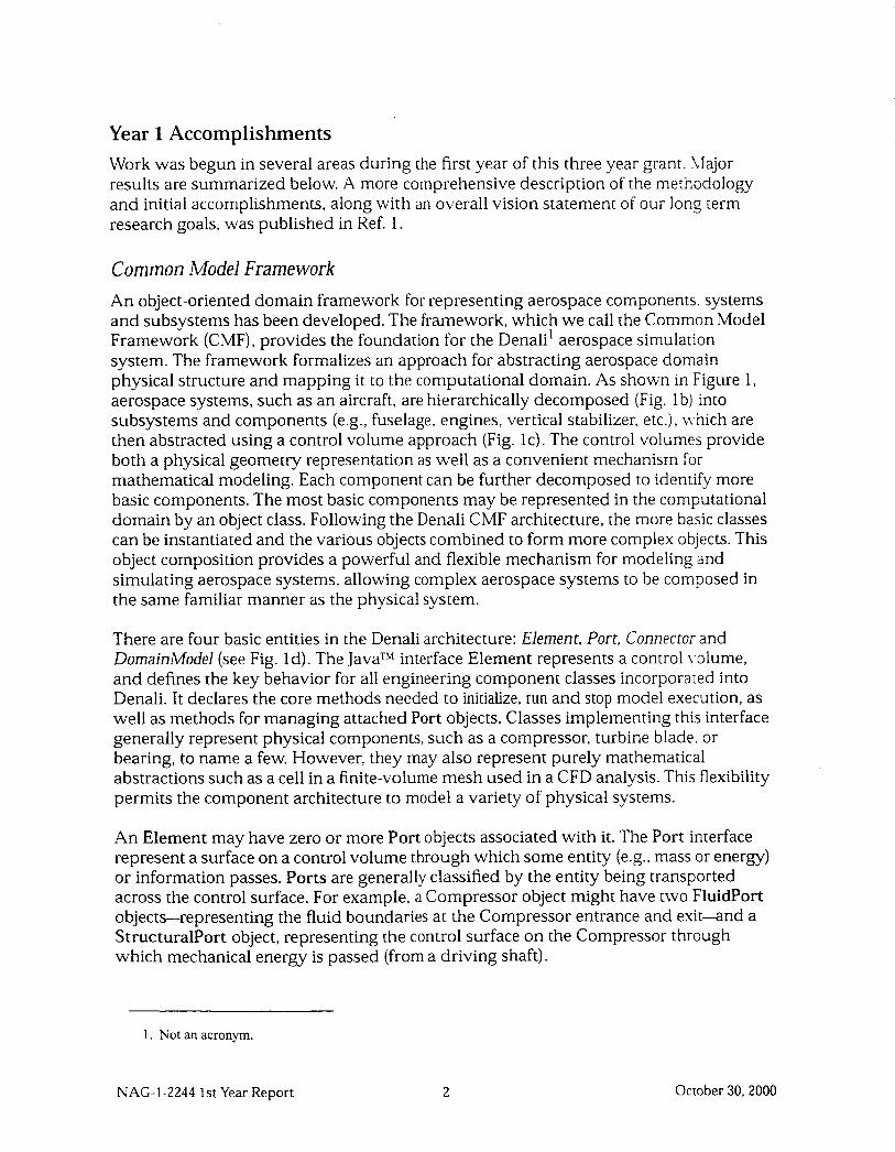
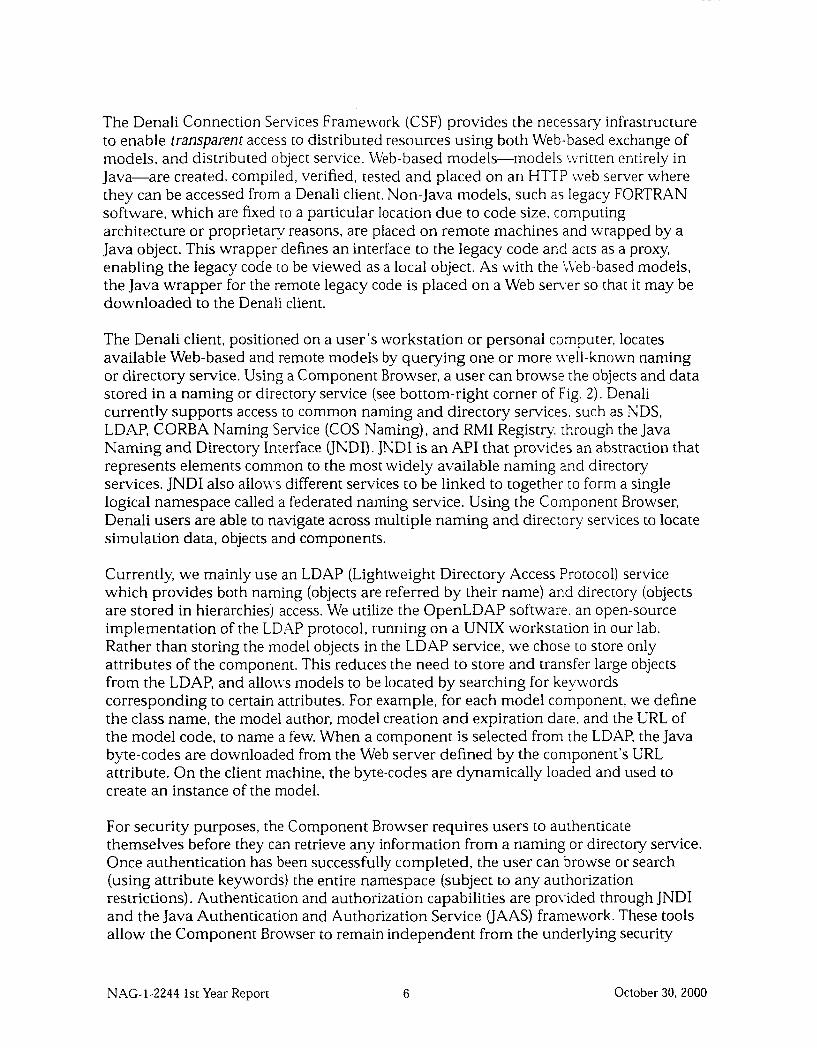
Common Model Framework An object-oriented domain framework for representing aerospace components. systems and subsystems has been developed. The framework, which we call the Common Model Framework (CMF) , provides the foundation for the Denali' aerospace simulation system. The framework formalizes an approach for abstracting aerospace domain physical structure and mapping it to the computational domain. As shown in Figure 1, aerospace systems, such as an aircraft, are hierarchically decomposed (Fig. lb) into subsystems and components (e.g., fuselage, engines, vertical stabilizer, etc.), Lvhich are then abstracted using a control volume approach (Fig. IC). The control volumes provide both a physical geometry representation as well as a convenient mechanism for mathematical modeling. Each component can be further decomposed to identiify more basic components. The most basic components may be represented in the computational domain by an object class. Following the Denali CMF architecture, the more basic classes can be instantiated and the various objects combined to form more complex objects. This object composition provides a powerful and flexible mechanism for modeling and simulating aerospace systems, allowing complex aerospace systems to be composed in the same familiar manner as the physical system.
There are four basic entities in the Denali architecture: Element, Port, Connector and DomainModel (see Fig. Id). The JavaTM interface Element represents a control \.olume, and defines the key behavior for all engineering component classes incorporated into Denali. It declares the core methods needed to initialize, run and stop model execution, as well as methods for managing attached Port objects. Classes implementing this interface generally represent physical components, such as a compressor, turbine blade. or bearing, to name a few. However, they may also represent purely mathematical abstractions such as a cell in a finite-volume mesh used in a CFD analysis. This flexibility permits the component architecture to model a variety of physical systems.
An Element may have zero or more Port objects associated with it. The Port interface represent a surface on a control volume through which some entity (e.g., mass or energy) or information passes. Ports are generally classified by the entity being transported across the control surface. For example, a Compressor object might have two FluidPort objects-representing the fluid boundaries at the Compressor entrance and exit-and a StructuralPort object, representing the control surface on the Compressor through which mechanical energy is passed (from a driving shaft).
1. Not an acronym.
NAG-1-2244 1st Year Report 2 October 30.2000
Control Volume /
J Control k . _.- . - _ _ _ Volume
" I
_- -
/
Structural Port
4 : 1
I : Fluid Element : Port
Figure 1: Mapping of aerospace physical domain to computational framework.
NAG-1-2244 1st Year Report 3 October 30, 2000
The common boundary between consecutive control volumes is represented by a Connector object. The interface Connector permits two Element objects to communicate by passing information between connected Port objects (see Fig. ld). It is also responsible for data transformation and mapping in situations where the data being passed from Ports is of different type. The need for such data transformation can range from simple situations, such as conversion of data units, to very complex ones involving a mismatch in model fidelity (e.g., connecting a 2-D fluid model to a 3-D fluid model) or disciplinary coupling (e.g. mapping structural analysis results from a finite-element mesh to a finite-volume mesh used for aerodynamic analysis). For all but the simplest cases, the algorithms needed to perform the data transformation or mapping will tend to be very complex. To improve reusability, Connector delegates transformation/mapping responsibilities to a separate Transform object (see Fig. Id) which encapsulates the necessary intelligence to expand/contract data and map data across disciplines.
The DomainModel represents the mathematical model used to define component behavior. During component design and analysis, many different models (i.e., multimodels) are used. During preliminary design the models are relatively simple and may be solved analytically or using basic numerical methods. However, models used in latter phases of design can be quite complicated. In these cases, approximate solutions are obtained by discretization of the equations on a geometrical mesh and applying highly specialized numerical solvers. The presence of these complex mathematical models and the numerical tools needed to solve them suggest that it is desirable to encapsulate these features and remove them from the Element structure. This enhances the modularity of Element, allowing new Element classes to be added without regard to the mathematical model used, and conversely to add new models without affecting the Element class. To achieve this, Denali utilizes the Strategy design pattern-to encapsulate the mathematical model in a separate object. The benefit of this pattern is that families of similar algorithms become interchangeable, allowing the algorithm-in this case the DomainModel-to vary independently from the Elements that use it. This admits the possibility of run-time selection of an appropriate DomainModel for a given Element: however, this is currently not used in Denali. Furthermore, encapsulating the DomainModel in a separate object also encourages the “wrapping” of pre-existing, external software packages. For example, the Fan DomainModel in Fig. Id might “wrap” a pre-existing three-dimensional Navier-Stokes or Euler flow solver to provide steady- state aerodynamic analysis of fluid flow within the Fan. This approach allows proven functionality of existing software analysis packages to be easily integrated within an Element.
The standard object interfaces of the Denali CMF ensure that each component object interoperates with other component objects. This is essential for providing a stable modeling environment which allows complex models to be developed using object composition and class inheritance. Furthermore, the standard interfaces of the CMF architecture provide a “pluggable” architecture wherein new components can be added at runtime.
NAG-1-2244 1st Year Report 4 October 30,2000
As an example application of the CMF, a model of a the NASA/GE Energy Efficient Engine (EEE) gas turbine aircraft engine was created. Elements representing the inlet, fan, compressor, combustor, shafts, turbines, nozzle and ducts in a turbofan engine were developed. The DomainModel for each Element was developed using a zero- dimensional mathematical treatment. Furthermore, only an aerothermodynamic disciplinary analysis was used. At this level of fidelity and discipline, component behavior was defined by the unsteady, space-averaged forms of the aerothermodynamic conservation equations. Empirical data, in the form of performance maps, were used to define operating behavior for rotating components, such as Compressors and Turbines. The component objects were combined using appropriate zero-dimensional fluid and mechanical Port and Connector objects. A Newton-Raphson numerical execution scheme (also provided as part of the Denali system) was used to sole the model equations and simulate both steady and unsteady engine operation. Results of the tests were validated against other existing FORTRAN gas turbine engine simulation programs.
Connection Services Frame work Aerospace design and analysis requires the interaction of many people at different geographic locations. Even if these individuals are part of the same company, today’s increasingly international business environment and corporate structures requires us to assume that the participants may not be at the same location. Moreover, strategic partnerships between companies (even those competing in the same business domain) are becoming more common place requiring additional interaction across company boundaries. As a result, it is important that our simulation framework enable users to collaborate by sharing models and data in a heterogeneous Lvork environment.
Denali supports the exchange of models through the use of mobile code. Mobile code is defined as program code which can be transferred from one computer to another and executed (without recompilation) on the receiving computer. An example of this is the Java byte-code which is executed on the receiving machine by a Java Virtual Machine interpreter. Denali utilizes this feature to allow designers to create, compile, verify and share Java-based component models. Following the design guidelines specified by the CMF, aerospace components are created, placed on a Web-server and downloaded to a Denali client. Once loaded to the client, the model can be combined without additional programming effort to form a new model.
In aerospace design and analysis, as in many other engineering domains, access to distributed resources is critical. The computationally intensive nature of higher fidelity analysis codes (such as Computational Fluid Dynamics) require access to high performance supercomputers or networks of workstations. Furthermore, the use of legacy code in aerospace design and analysis often require access to codes that are constrained to run on specific architectures or operating systems. As a result, it is important that our simulation framework enable users to access the appropriate computing resources for the target application.
NAG-1-2244 1st Year Report 5 October 30. 2000
The Denali Connection Services Framecvork (CSF) provides the necessary infrastructure to enable transparent access to distributed resources using both Web-based exchange of models, and distributed object service. Web-based models-models ivritten entirely in Java-are created, compiled, verified, tested and placed on an HT’TP web server where they can be accessed from a Denali client. Non-Java models, such as legacy FORTRAN software, which are fixed to a particular location due to code size, computing architecture or proprietary reasons, are placed on remote machines and wrapped by a Java object. This wrapper defines an interface to the legacy code and acts as a proxy, enabling the legacy code to be viewed as a local object. As with the ICeb-based models, the Java wrapper for the remote legacy code is placed on a Web sener so that it may be downloaded to the Denali client.
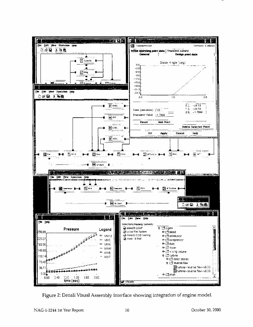
The Denali client, positioned on a user’s workstation or personal computer, locates available Web-based and remote models by querying one or more n.ell-known naming or directory service. Using a Component Browser, a user can browse the objects and data stored in a naming or directory service (see bottom-right corner of Fig. 2). Denali currently supports access to common naming and directory services. such as NDS, LDAP, CORBA Naming Service (COS Naming), and RMI Registry. through the Java Naming and Directory Interface UNDI). JNDI is an API that provides an abstraction that represents elements common to the most widely available naming and directory services. JNDI also alloLvs different services to be linked to together to form a single logical namespace called a federated naming service. Using the Component Browser, Denali users are able to navigate across multiple naming and direcrory services to locate simulation data, objects and components.
Currently, we mainly use an LDAP (Lightweight Directory Access Protocol) service which provides both naming (objects are referred by their name) and directory (objects are stored in hierarchies) access. We utilize the OpenLDAP software. an open-source implementation of the LDAP protocol, running on a UNIX workstation in our lab. Rather than storing the model objects in the LDAP service, we chose to store only attributes of the component. This reduces the need to store and transfer large objects from the LDAP, and allo\vs models to be located by searching for ke_ywords corresponding to certain attributes. For example, for each model component, we define the class name, the model author, model creation and expiration date, and the LRL of the model code, to name a few. When a component is selected from the LDAP, the Java byte-codes are downloaded from the Web server defined by the component’s LRL attribute. On the client machine, the byte-codes are dynamically loaded and used to create an instance of the model.
For security purposes, the Component Browser requires users to authenticate themselves before they can retrieve any information from a naming or directory service. Once authentication has been successfully completed, the user can browse or search (using attribute keywords) the entire namespace (subject to any authorization restrictions). Authentication and authorization capabilities are provided through JNDI and the Java Authentication and Authorization Service UAAS) framework. These tools allow the Component Browser to remain independent from the underlying security
NAG-1-2244 1st Year Report 6 October 30, 2000
services, which is an important concern when working in a heterogeneous computing environment such as the Web.
Access and utilization of both Web-based and remote legacy models ha\.e been tested successfully using the Denali CSF. Component models for the EEE gas [urbine engine model were placed on a Web server (rnimel) located in our lab. Each component model, with the exception of the Combustor, was defined as a Web-based model (i.e., written in Java). For this test, a FORTRAN Combustor model, representing non-Java legacy codes, was written, compiled and placed on a second machine (mime2). A Java ivrapper, acting as a proxy for the Combustor model, was written, compiled and placed on the Web server (mime 1). Deployment of each component also included registering component attributes with the LDAP service running on a third machine (mime3). A Denali client, operating on a fourth machine (mime4), was then used to access and construct the EEE engine system model using the Denali Visual Assembly Framework, Lvhich is described below.
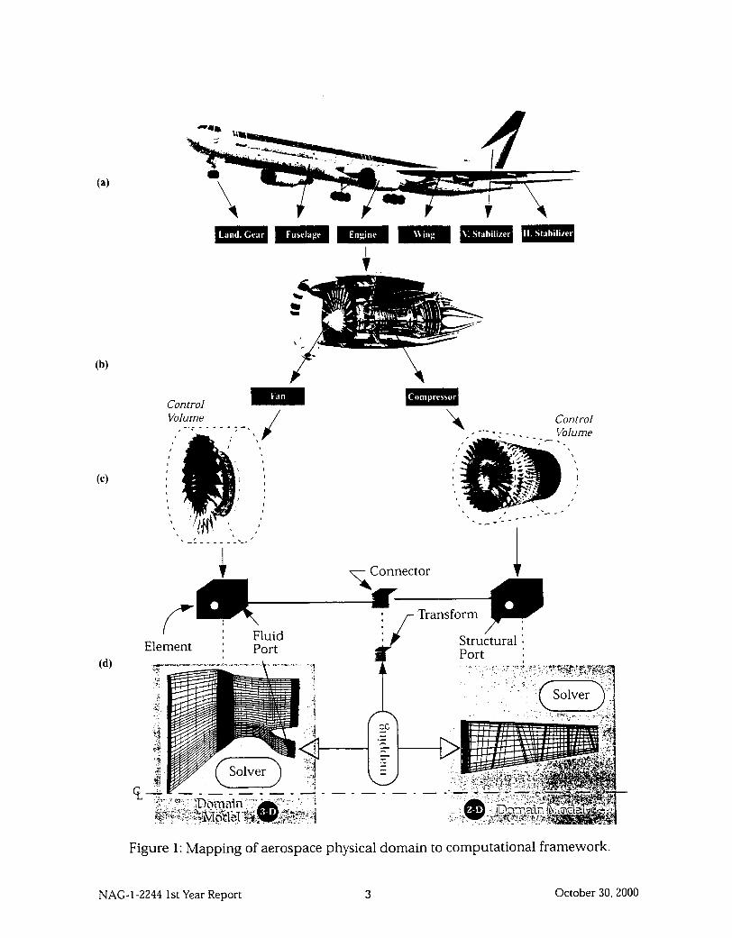
Visual Assembly Framework The Visual Assembly Frameic-ork (VAF) provides a configurable, extensible graphical interface for constructing and editing Denali component and system models. Aerospace component objects, placed on Web servers and registered in the LDAP service are graphically manipulated in the VAF to create new models, or edit existing models. Icons, representing individual engine components (i.e., Elements), are selected from the Component Browser, dragged into a workspace window, and interconnected to form a schematic diagram (see Fig. 2). Dragging an icon from the Component 3rowser to the workspace window causes the selected software component to be doimloaded from the Web server to the client machine. Components comprised entirely of Ja\.a classes are downloaded from a Web server to the local file system where the byte-codes are extracted from the JAR file, loaded into the Java Virtual Machine and insIantiated for use in Denali. Components developed in other programming languages are not downloaded, but remain on the server. Instead, the proxy object, representing the component, is downloaded and used to connect to the remote component using the Java Remote Method Invocation (RMI) substrate.
Denali supports the creation of hierarchical component models, and an icon can represent both a single component or an assembly of components. A component with subcomponents is called a composite or structured component. Components that are not structured are called primitive components, since they are typically defined in terms of primitives such as variables and equations. Composite components are represented by a CompositeElement class, which is part of the Element hierarchy. The class structure, based on the Composite design pattern, effectively captures the part-ivhole hierarchical structure of the component models, and allows the uniform treatment of both individual objects and compositions of objects. Such treatment is essential for pro\-iding the object interoperability needed to perform Web-based model construction by composition.
NAG-1-2244 1st Year Report 7 October 30,2000
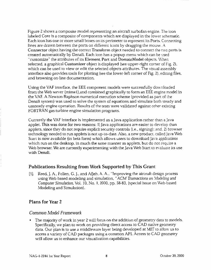
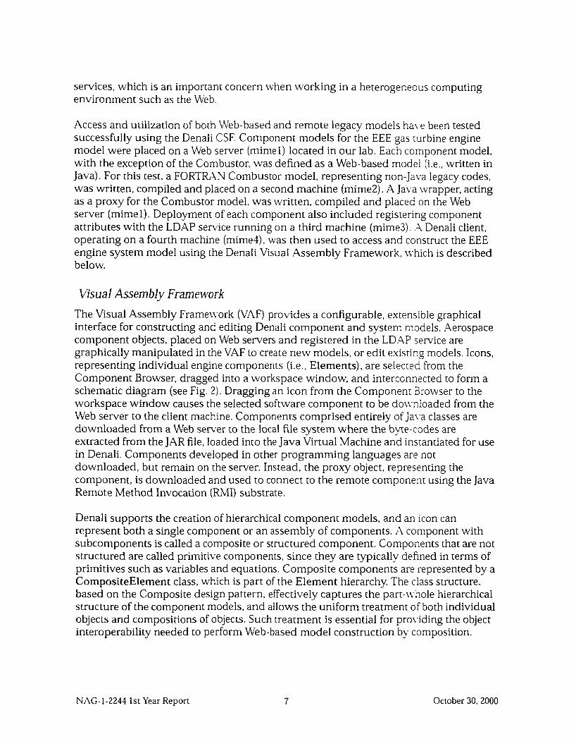
Figure 2 shows a composite model representing an aircraft turbofan engine. The icon labeled Core is a composite of components which are displayed in the lower schematic. Each icon has one or more small boxes on its perimeter to represent its Ports. Connecting lines are drawn between the ports on different icons by dragging the mouse. A Connector object having the correct Transform object needed to connect the two ports is created automatically by Denali. Each icon has a popup menu which can be used “customize” the attributes of its Element, Port and DomainModel objects. LVhen selected, a graphical Customizer object is displayed (see upper-right corner of Fig. 2), which can be used to view or edit the selected objects attributes. The visual assembly interface also provides tools for plotting (see the lower-left corner of Fig. 2), editing files, and browsing on-line documentation.
Using the VAF interface, the EEE component models were successfully downloaded from the Web server (mimel),and combined graphically to form an EEE engine model in the VAF. A Newton-Raphson numerical execution scheme (provided as parr of the Denali system) was used to solve the system of equations and simulate both steady and unsteady engine operation. Results of the tests were validated against other exis[ing FORTRAN gas turbine engine simulation programs.
Currently the VAF interface is implemented as a Java application rather than a Java applet. This was done for two reasons: 1) Java applications are easier to develop [han applets, since they do not require explicit security controls (i.e., signing) : and. 2) browser technology needed to run applets is not up-to-date. Also, a new product. called Java Web Start is now available (in beta form) which allows users to download Java applicarions which run on the desktop, in much the same manner as applets, but do not require a Web browser. We are currently experimenting with the Java Web Start to evaluate its use with Denali.
Publications Resulting from Work Supported by This Grant [l] Reed, J. A., Follen, G. J., and Afjeh, A. A., “Improving the aircraft design process
using Web-based modeling and simulation, “ ACM Transactions on Modeling and Computer Simulation, Vol. 10, No. 1,2000, pp. 58-83, (special issue on Web-based Modeling and Simulation).
Plans for Year 2
Common Model Framework The majority of work in year 2 will focus on the addition of geometry data to models. Specifically, we plan to work on providing direct access to CAD native geometry data. Our plan is to use a middleware layer being developed at MIT to alloiv us to access a variety of CAD packages using a common API. Access to CAD geometry will allow us to enhance our visualization capabilities.
NAG-1-2244 1st Year Report 8 October 30, 2000
We plan to test integration of several database management systems with Denali. This had been slated for yr. 1, but was postponed until yr. 2 to more fully explore the use of new approaches to saving models, such as using XML.
We also plan to obtain existing airframe models for study. These will be integrated within the Denali simulation system in year 3.
Connection Services Frame work We will continue to improve non-mobile code services. Specifically, we are working on developing generalized specifications for wrapping legacy codes common in the aerospace domain. These include CFD and FEA tools, as well as numerical solvers and optimizers.
Visual Assembly Framework We will work on integration of CFD and geometry visualization. We will examine the possibility of integrating an existing visualization tool, or creating a new Java-based visualization tool to display geometry and flow data.
We \vi11 continue to enhance and refine our VAF design to make it more intuitive and easier to use. We hope to provide a beta version of the Denali system to users at aerospace companies and NASA centers for evaluation. Feedback from these beta testers will be used to enhance the Denali VAF (and other parts of Denali).
NAG-1-2244 1st Year Report 9 October 30, 2000
.I I I--- I I
Stator lng le ‘3eg) 0 0 -_ - __
-3 0 - ,. -6 0 - -9 0 - /
-120. I
-15 0 - /’ -18 0 - -21 0 . -24 0 ,’
/
, 0 0 1 0 2 0
0 0 , - 2 4 9 9 1 3 -2499 20, - 1 7004 I lime (seconds) 2 00
Transient Value - 1 7004
--_-A Reset Add Point I
Figure 2: Denali Visual Assembly interface showing integration of engine model.
October 30.2000 NAG-1-2244 1st Year Report 10
A second year progress report on:
Development of a Dynamically Configurable, Object-Oriented Framework for Distributed, Multi-modal Computational Aerospace Systems Simulation
Abdollah A. Afjeh, Ph.D. John A. Reed, Ph.D.
Department of Mechanical, Industrial and Manufacturing Engineering The University of Toledo
September 7,2001
Summary This report describes the progress made in the second year (Sept. 1,2000 to Aug. 31,2001) of work at The University of Toledo under the NASA Information Technology (IT) Program grant number NAG-1-2244. This research is aimed at developing a new and advanced simulation framework that will significantly improve the overall efficiency of aerospace systems design and development. This objective will be accomplished through an innovative integration of object-oriented and Web-based technologies with both new and proven simulation methodologies. The basic approach involves three major areas of research:
Aerospace system and component representation using a hierarchical object-oriented component model which enables the use of multimodels and enforces component interoperability.
Collaborative software environment that streamlines the process of developing, sharing and integrating aerospace design and analysis models.
Development of a distributed infrastructure which enables Web-based exchange of models to simplify the collaborative design process, and to support computationally intensive aerospace design and analysis processes.
Research for the second year focused on enabling models developed in the Dennli software environment to directly access CAD native geometry. Access to CAD geometry is essential to generate mesh for use in fluid and structural analysis of aerospace systems, as well as visualization of analysis results. Furthermore, a geometry-centric modeling approach, as employed in this work, simplifies use of these and other tools in a multidisciplinary design process. Finally, direct access to CAD native geometry, compared to geometry described in intermediate forms (e.g., IGES['I* STEP[*], STL13], etc.), is more robust.
NAG-1-2244 2nd Year Report 1 September 7,2001
Year 2 Accomplishments
CAD
In trod iiction Computational simulation plays an essential role in the aerospace design process. Computer-aided design (CAD) methods are the basic tool for definition and control of the configuration, ard CAD solid modeling capabilities enable designers to create virtual mockups of system to verify that no .nterferences exist in part layouts. Similarly, structural analysis is almost entirely performed using con;xtational tools employing finite element methods. Computational simulation is also employed :c model fluid dynamics. However, computation fluid dynamic (CFD) tools are not as widely applied in the zesign process as either CAD or structural analysis tools due, in part, to the long set-up times and high COS:^ (both human and computational) associated with complex fluid flow.[']
' * Meshing + Solving I + Iisualization
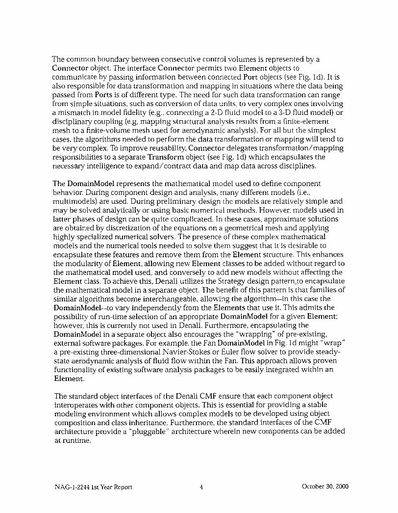
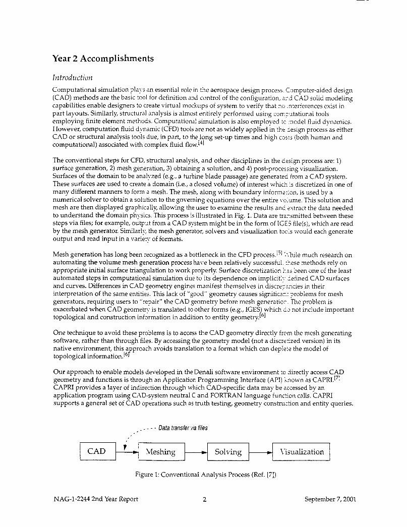
The conventional steps for CFD, structural analysis, and other disciplines in the design process are: 1) surface generation, 2) mesh generation, 3) obtaining a solution, and 4) post-processing visualization. Surfaces of the domain to be analyzed (e.g., a turbine blade passage) are generated from a CAD system. These surfaces are used to create a domain (i.e., a closed volume) of interest which is discretized in one of many different manners to form a mesh. The mesh, along with boundary informZ?on, is used by a numerical solver to obtain a solution to the governing equations over the entire 1-c:ilme. This solution and mesh are then displayed graphically, allowing the user to examine the results ani: 2xtract the data needed to understand the domain physics. This process is illustrated in Fig. 1. Data are trznsmitted between these steps via files; for example, output from a CAD system might be in the form of I G E file(s), which are read by the mesh generator. Similarly, the mesh generator, solvers and visualization took would each generate output and read input in a variev of formats.
Mesh generation has long been recognized as a bottleneck in the CFD process.['; :?lule much research on automating the volume mesh generation process have been relatively successful. r5ese methods rely on appropriate initial surface triangulation to work properly. Surface discretization ;7'j been one of the least automated steps in computational simulation due to its dependence on implicitl:: iefined CAD surfaces and curves. Differences in CAD peometry engines manifest themselves in discrerzcies in their interpretation of the same entities. This lack of "good" geometry causes signific2.r.r ?roblems for mesh generators, requiring users to "repair" the CAD geometry before mesh generatior.. The problem is exacerbated when CAD geomem is translated to other forms (e.g., IGES which La not include important topological and construction information in addition to entity geometry. t61
One technique to avoid these problems is to access the CAD geometry directly frcm the mesh generating software, rather than through files. By accessing the geometry model (not a discrefzed version) in its native environment, t h s a proach avoids translation to a format which can deplere the model of topological information. [ 6 f
Our approach to enable models developed in the Denali software environment to iirectly access CAD geometry and functions is through an Application Programming Interface (API) h o w n as CAPRI.171 CAPRI provides a layer of indirection through which CAD-specific data may be accessed by an application program using CAD-system neutral C and FORTRAN language funceon calls. CAPRI supports a general set of CAD operations such as truth testing, geometry construction and entity queries.
- - - - Data transfer via files
Figure 1: Conventional Analysis Process (Ref. [7])
NAG-1-2244 2nd Year Report 2 September 7,2001
CAD L
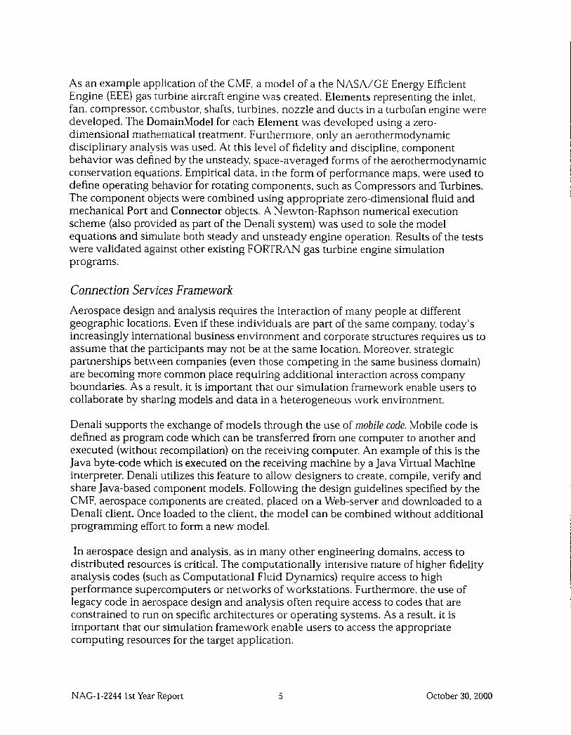
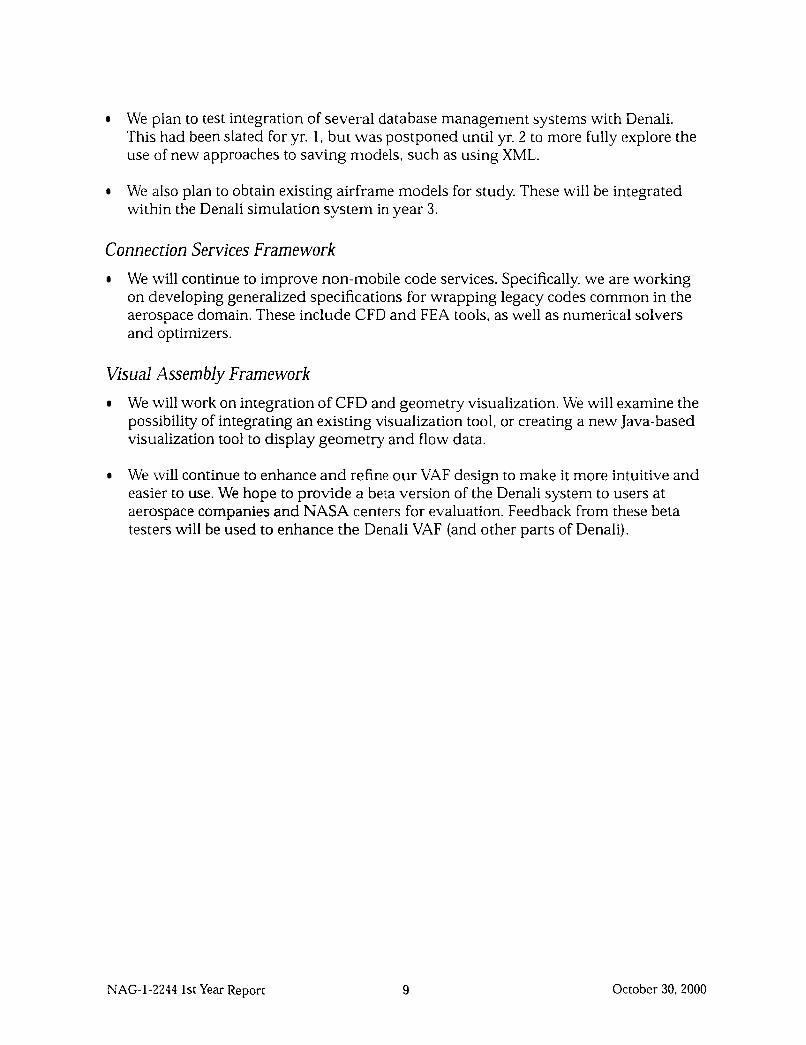
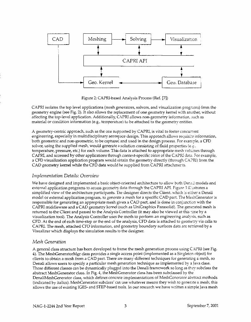
Figure 2: CAPRI-based Analysis Process (Ref. [7])
Meshing w Solving Visualization
CAPRI isolates the top level applications (mesh generators, solvers, and visualization programs) from the geometry engine (see Fig. 2) . It also allows the replacement of one geometry kernel with another, without affecting the top-level application. Additionally, CAPRI allows non-geometry information, such as material or condition information (e.g., temperature) to be attached to the geometry entities.
i A I
CAPRI API 4 7 I - Geo. Kernel t * Geo. Database
A geometry-centric approach, such as the one supported by CAPRI, is vital to foster concurrent engineering, especially in multidisciplinary aerospace design. This approach allows requisi:? information, both geometric and non-geometric, to be captured and used in the design process. For exam?le, a CFD solver, using the supplied mesh, would generate a solution consisting of fluid properties (e.g., temperature, pressure, etc.) for each volume. Ths data is attached to appropriate mesh vol.;nes through CAPRI, and accessed by other applications through context-specific views of the CAPRI data. For example, a CFD visualization application program would obtain the geometry directly (through CAPRI) from the CAD geometry kernel while the CFD data would be supplied from CAPRI attachments.
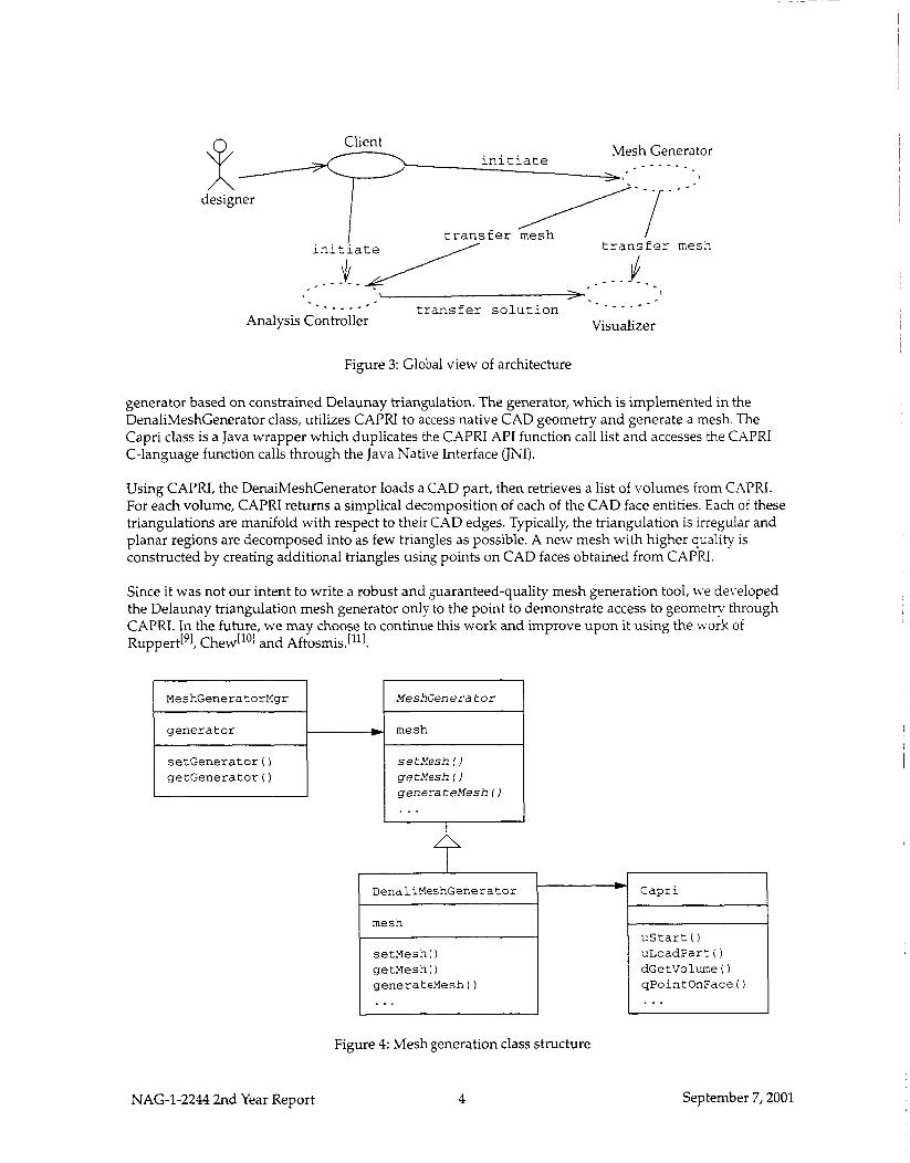
Implementation Details: Overviezo We have designed and implemented a basic object-oriented architecture to allow both Der.2-i models and external application programs to access geometry data through the CAPRI API. Figure 3 ii:,strates a simplified view of the architecture participants. The designer directs the Client, which is eiri.,er a Denali model or external application program, to generate a mesh for a specific CAD part. The MeshGenerator is responsible for generating an appropriate mesh given a CAD part, and is done in conjuncEcn with the CAPRI middleware and a CAD geometry kernel (such as UniGraphics Parasolid). The generated mesh is returned to the Client and passed to the Analysis Controller (it may also be viewed at this !me by a visualization tool). The Analysis Controller uses the mesh to perform an engineering analJ-sis, such as CFD. At the end of each time-step or the end of the analysis, CFD data is attached to geomerry via calls to CAPRI. The mesh, attached CFD information, and geometry boundary surfaces data are retrieved by a Visualizer which displays the simulation results to the designer.
Mesh Generation A general class structure has been developed to frame the mesh generation process using C.\PRI (see Fig. 4). The MeshGeneratorMgr class provides a single access point (implemented as a Singleton object) for clients to obtain a mesh from a CAD part. There are many different techniques for generating a mesh, so Denali allows users to specify a particular mesh generation technique as implemented by a lava class. These different classes can be dynamically plugged into the Denali framework so long as they subclass the abstract MeshGenerator class. In Fig. 4, the MeshGenerator class has been subclassed by the DenaliMeshGenerator class, which defines concrete implementations of MeshGenerator abstract methods (indicated by italics). MeshGenerator subclass’ can use whatever means they wish to generate a mesh; this allows the use of existing IGES- and STEP-based tools. In our research we have written a simple Java mesh
NAG-1-2244 2nd Year Report 3 September 7,2001
Client Mesh Generator initiate _ - - - _
1 1.'
MeshGeneratorMgr
generator
setGenerator ( )
getGenerator ( 1
A designer
MeshGenera t o r
mesh
se tMesh ( )
ge tMesh I ) genera teMesh ( I
i
DenaliMeshGenerator -
/ - -7 * - - .
Capri
transfer mesh I / transfer mesh I
initiate
- - _ _ _ - - transfer solution - - _ _ _ - - Analysis Controller Visualizer
Figure 3: Global view of architecture
generator based on constrained Delaunay triangulation. The generator, which is implemented in the DenaliMeshGenerator class, utilizes CAPRI to access native CAD geometry and generate a mesh. The Capri class is a Java wrapper which duplicates the CAPRI API function call list and accesses the CAPRI C-language function calls through the Java Native Interface (JNI).
Using CAPRI, the DenaiMeshGenerator loads a CAD part, then retrieves a list of volumes from CAPRI. For each volume, CAPRI returns a simplical decomposition of each of the CAD face entities. Each of these triangulations are manifold with respect to their CAD edges. Typically, the triangulation is irregular and planar regions are decomposed into as few triangles as possible. A new mesh with higher quality is constructed by creating additional triangles using points on CAD faces obtained from CAPRI.
Since it was not our intent to write a robust and guaranteed-quality mesh generation tool, lve developed the Delaunay triangulation mesh generator only to the point to demonstrate access to geometrl; through CAPRI. In the future, we may choose to continue this work and improve upon it using the work ot' Ruppert['I, Chew["] and Aftosmis.["].
NAG-1-2244 2nd Year Report
setMeshl) getMesh ( )
generateMesh ( )
Figure 4: Mesh generation class structure
4
uStart t ) uLoadParz ( )
dGetVolune ( ) qPointOnFace ( )
September 7,2001
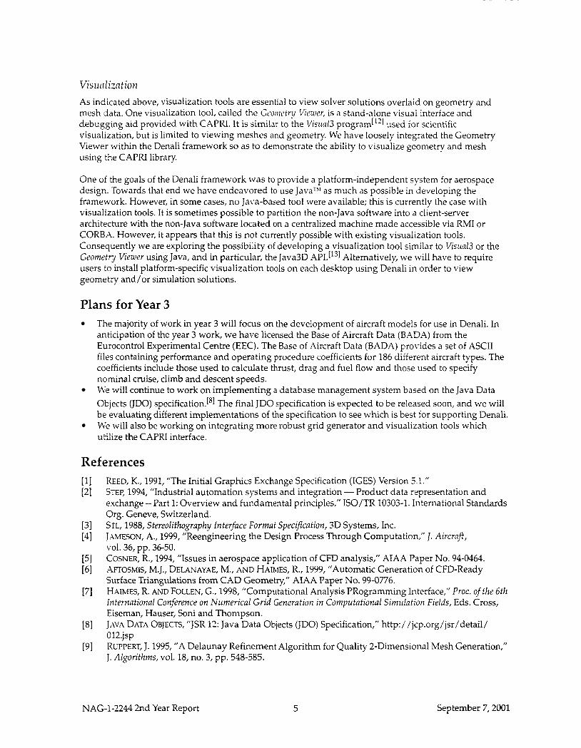
Visirdization As indicated above, visualization tools are essential to view solver solutions overlaid on geometry and mesh data. One visualization tool, called the Gcornctry Viezorr, is a stand-alone visual interface and debugging aid provided with CAPRI. It is similar to the Visual3 program[”] used for scientific visualization, but is limited to viewing meshes and geometry. We have loosely integrated the Geometry Viewer withn the Denali framework so as to demonstrate the ability to visualize geometry and mesh using the CAPRI library.
One of the goals of the Denali framework was to provide a platform-independent system for aerospace design. Towards that end we have endeavored to use JavaTh’ as much as possible in developing the framework. However, in some cases, no Java-based tool were available; this is currently the case with visualization tools. It is sometimes possible to partition the non-Java software into a client-server architecture with the non-Java software located on a centralized machine made accessible via RMI or CORBX. However, it appears that this is not currently possible with existing visualization tools. Consequently we are exploring the possibility of developing a visualization tool similar to Visital3 or the Geometry Viewer using Java, and in particular, the Java3D users to install platform-specific visualization tools on each desktop using Denali in order to view geometry and/or simulation solutions.
Alternatively, we will have to require
Plans for Year 3 The majority of work in year 3 will focus on the development of aircraft models for use in Denali. In anticipation of the year 3 work, we have licensed the Base of Aircraft Data (BADA) from the Eurocontrol Experimental Centre (EEC). The Base of Aircraft Data (BADA) provides a set of ASCII files containing performance and operating procedure coefficients for 186 different aircraft types. The coefficients include those used to calculate thrust, drag and fuel flow and those used to specify nominal cruise, climb and descent speeds. We will continue to work on implementing a database management system based on the Java Data Objects (JDO) specification.[’] The final JDO specification is expected to be released soon, and we will be evaluating different implementations of the specification to see which is best for supporting Denali. We will also be working on integrating more robust grid generator and visualization tools which utilize the CAPRI interface.
References REED, K., 1991, ”The Initial Graphics Exchange Specification (IGES) Version 5.1.” STEP, 1994, “Industrial automation systems and integration - Product data representation and exchange -- Part 1: Overview and fundamental principles,” ISO/TR 10303-1. International Standards Org. Geneve, Switzerland. STL, 1988, Stereolithography Interface Format Specification, 3D Systems, Inc. JAMESON, A., 1999, “Reengineering the Design Process Through Computation,” I. Aircraft,
COSNER, R., 1994, “Issues in aerospace application of CFD analysis,” AIAA Paper No. 94-0464. AFTOSMIS, M.J., DELANAYAE, M., AND HAIMES, R., 1999, “Automatic Generation of CFD-Ready Surface Triangulations from CAD Geometry,” AIAA Paper No. 99-0776. HAIMES, R. AND FOLLEN, G., 1998, “Computational Analysis PRogramming Interface,” Proc. of the 6th ltiternational Conference on Numerical Grid Generation in Computational Sitnillation Fields, Eds. Cross, Eiseman, Hauser, Soni and Thompson. JAVA DATA OBJECTS, “JSR 12: Java Data Objects (JDO) Specification,” http:/ /jcp.org/jsr/detail/ 012.jsp RUPPERT, J. 1995, “A Delaunay Refinement Algorithm for Quality 2-Dimensional Mesh Generation,” J. Algorithms, vol. 18, no. 3, pp. 548-585.
V O ~ . 36, pp. 36-50.
NAG-1-2244 2nd Year Report 5 September 7,2001
[lo]
[ll]
[12]
[13]
CHEW, L. P., 1993, ”Guaranteed-quality mesh generation for curved surfaces,” Proc. of the Ninth Annual Symposium on Computational Geometry, pp. 274-280, ACM. AFTOSMIS, M.J., 1999, “On the Use of CAD-Native Predicates and Geometry in Surface Meshing,”
HAIMES, R., 1991, “Visual3: Interactive Unsteady Unstructured 3D Visualization,” AIAA Paper No.
SOWIZRAL, H., RUSHFORTH, K., AND DEERING, M., 2000, The Java 3DTM API Specification, Second Edition, Addison Wesley Longman, Inc. ISBN: 0-201-71041-2
NASA TM-1999-208782.
91-0794.
NAG-1-2244 2nd Year Report 6 September 7,2001
APPENDIX B: Publications
Conference Publications
1. Lin, Risheng and Afjeh, A. A., “An Extensible, Interchangeable and Sharable Database Model for Improving Multidisciplinary Aircraft Design,” AlAA 2002- 561 3, 9th AIANISSMO Symposium on Multidisciplinary Analysis and Optimization, 4 - 6 September 2002, Atlanta, Georgia.
2. Lin, Risheng and Afjeh, A. A., “Interactive, Secure Web-enabled Aircraft Engine Simulation Using XML Databinding Integration,” AlAA 2002- 4058, 38th AIANASME/SAE/ASEE Joint Propulsion Conference & Exhibit, 7 - 10 July 2002, Indianapolis, Indiana.
Journal Articles
3. Reed, J. A., Follen, G. J., and Afjeh, A. A., “Improving the aircraft design process using Web-based modeling and simulation, “ACM Transactions on Modeling and Computer Simulation, Vol. 10, No. 1,2000, pp. 58-83, (special issue on Web-based Modeling and Simulation).
4. Lin, Risheng and Afjeh, A. A., “On XML-based Integrated Database Model for Multidisciplinary Aircraft Design,” AlAA Journal of Aerospace Computing, Information, and Communication, To appear in 2004.
A I M 2002- 5613
An Extensible, Interchangeable and Sharable Database Model for Improving Multidisciplinary Aircraft Design Risheng Lin and Abdollah A. Afjeh The University of Toledo Toledo, Ohio
9th AlAAllSSMO Symposium on Multidisciplinary Analysis and Optimization 4 - 6 September 2002
Atlanta, Georgia
For permission to copy or to republish, contact the copyright owner named on the first page. For AIM-held copyright, write to A I M Permissiorts Department,
1801 Alexander Bell Drive, Suite 500, Reston, VA, 201914344.
A1.A 1-2002-5613
AN EXTENSIBLE, INTERCHANGEABLE AND SHARABLE D-ATABASE MODEL FOR IMPROVI3G MULTIDISCIPLINARY AIRCRAFT DESIGN
Risheng Lin' and Xbdollah A. Afjeh' The University of Toledo 2801 West Bancroft Street Toledo, Ohio 43606. USA
ABSTRACT
Advances in computer capacity and speed together with increasing demands on efficiency of aircraft design process have intensified the use of simulation-based analysis tools to explore design alternatives both at the component and system levels. High fidelity engineering simulation, typically needed for aircraft design, will require extensive computational resources and database support for the purposes of design optimization as many disciplines are necessarily involved. Even relatively simplified models require exchange of large amounts of data among various disciplinary analyses. Crucial to an efficient aircraft simulation-based design therefore is a robust data modeling methodology for both recording the information and providing data transfer readily and reliably. To meet this goal, data modeling issues involved in the aircraft multidisciplinary design are first analyzed in this study. Next, an XML-based. extensible data object model for multidisciplinary aircraft design is constructed and implemented. The implementation of the model through aircraft databinding allows the design applications to access and manipulate any disciplinary data with a lightweight and easy-to-use API. In addition, language independent representation of aircraft disciplinary data in the model fosters interoperability amongst heterogeneous systems thereby facilitating data sharing and exchange between various design tools and systems.
INTRODUCTION
Improvement in aircraft design involves research into many distinct disciplines: aerodynamics, structures. propulsion, noise, controls, and others. Due to the inherent complexity and coupling of the disciplinary design issues, simulation-based analyses of aircraft design will naturally evolve to complex assemblies of dynamically interacting disciplines where each of the
* Rcsearch Associate, Student Member AIAA. Dcpanment of Mcchanicai. Industrial and Manufacturing Engincering. E-mail: rlin Scng.utolcdo.cdu + Profcssor and Chair, Department of Mechanical. Industrial and Manufacturing Engineering. Member AIAA. E-mail: aaijeh~.cng.utoledo.cdu Copyright ? 2007 by Risheng Lin. Published by the Amencan Institute of Acronautics and Astronautics, Inc.. with permission.
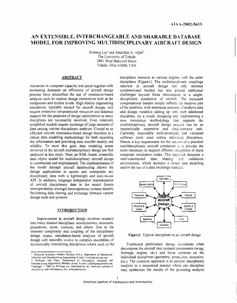
disciplines interacts to various degrees x i th the other disciplines (Figurel). The multidisciplinary couplings inherent in aircraft design not snly increase computational burden but also piesent additional challenges beyond those encountertd in a single- disciplinary simulation of aircraft. The increased computational burden simply reflects :it massive size of the problem, with enormous amounts zfanalysis data and design variables adding up with :ach additional discipline. As a result, designing and xplementing a new simulation methodology that jupports the multidisciplinary aircraft design prostjj can be an impractically expensive and timc-:r,vnsive task. Currently reasonably well-developed and validated software tools exist within ind iv icd disciplines. Hence, a key requirement for the S U C C ' t - j of a practical multidisciplinary aircraft simulation is :a provide the tools necessary to support efficient im=nt ion of these computer simulation codes. This appr,-:sh demands a well-constructed data sharing xi validation environment, which includes a robusr iata modeling andlor the use of a data exchange standz-d.
...I Geometry 1.
Materials
Acoustics
Figurel. Typical disciplines in an xcraf t design
Traditional preliminary design 7rscedures often decompose the aircraft into isolated components (wing, fuselage, engine, etc.) and focus ancntion on the individual disciplines (geometry. propulsion, acoustics, etc.). The common approach is to perform disciplinary analysis in a sequential manner Lvhert one discipline may synthesize the results of the preceding analysis
1 American Institute of Aeronautics and Astronautics
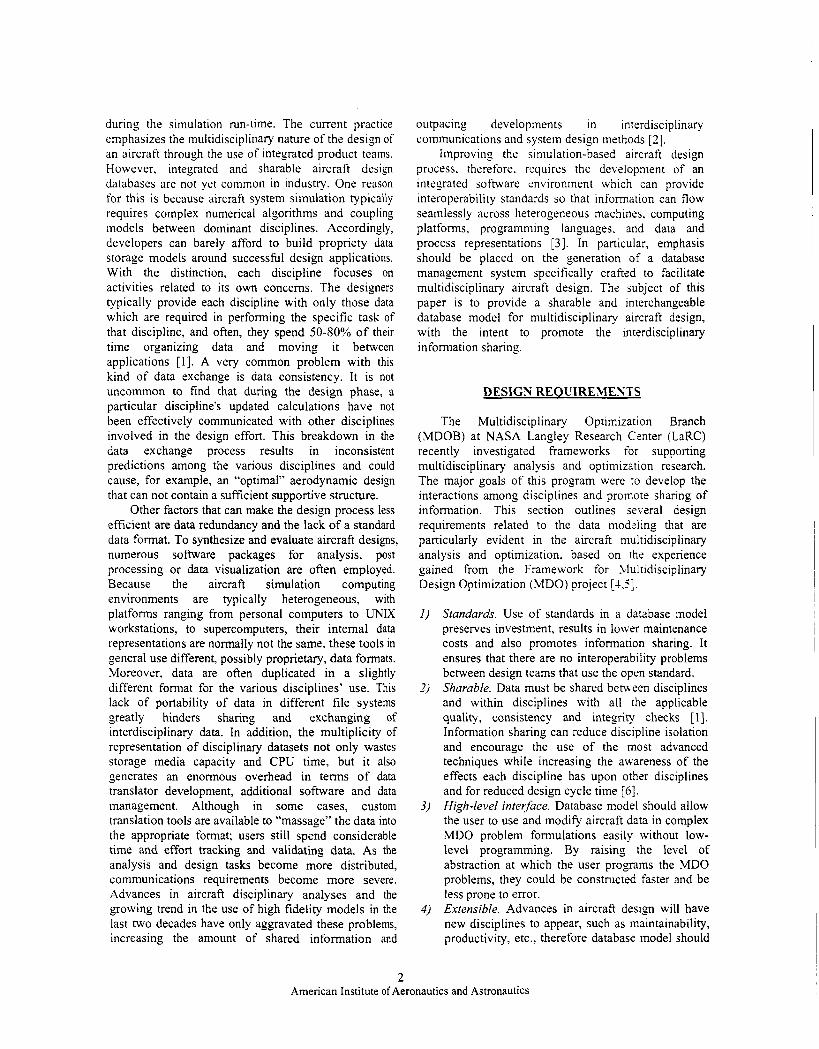
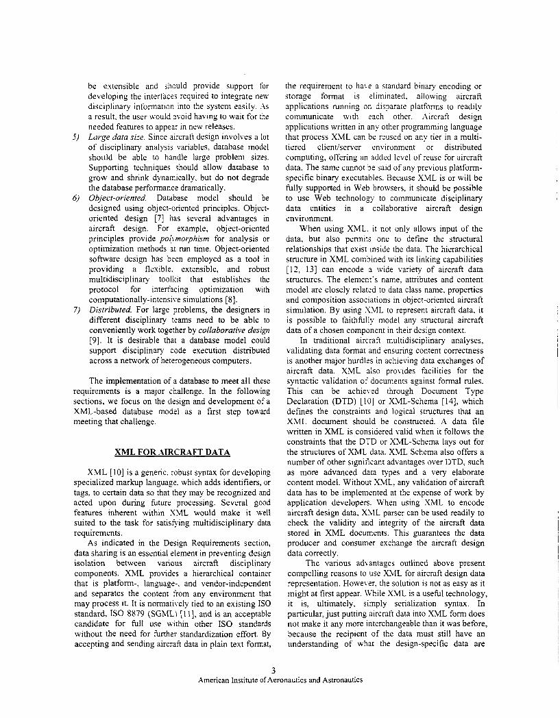
during the simulation run-time. The current practice emphasizes the multidisciplinary nature of the design of an aircraft through the use of integrated product teams. However, integrated and sharable aircraft design databases arc not yet common in industry. One reason for this is because aircraft system simulation typically requires complex numerical algorithms and coupling models between dominant disciplines. Accordingly, developers can barely afford to build propriety data storage models around successful design applications. With the distinction, each discipline focuses on activities related to its own concerns. The designers typically provide each discipline with only those data which are required in performing the specific task of that discipline, and often, they spend 5040% of their time organizing data and moving it between applications [I] . A very common problem with this kind of data exchange is data consistency. It is not uncommon to find that during the design phase, a particular discipline’s updated calculations have not been effectively communicated with other disciplines involved in the design effort. This breakdown in the data exchange process results in inconsistent predictions among the various disciplines and could cause, for example, an “optimal” aerodynamic design that can not contain a sufficient supportive structure.
Other factors that can make the design process less efficient are data redundancy and the lack of a standard data format. To synthesize and evaluate aircraft designs, numerous software packages for analysis, post processing or data visualization are often employed. Because the aircraft simulation computing environments are typically heterogeneous, with platforms ranging from personal computers to UNIX workstations, to supercomputers, their internal data representations are normally not the same, these tools in general use different, possibly proprietary, data formats. Moreover, data are often duplicated in a slightly different format for the various disciplines’ use. This lack of portability of data in different file systems greatly hinders sharing and exchanging of interdisciplinary data. In addition, the multiplicity of representation of disciplinary datasets not only wastes storage media capacity and CPU time, but it also generates an enormous overhead in terms of data translator development, additional software and data management. Although in some cases, custom translation tools are available to “massage” the data into the appropriate format; users still spend considerable time and effort tracking and validating data. As the analysis and design tasks become more distributed, communications requirements become more severe. Advances in aircraft disciplinary analyses and the growing trend in the use of high fidelity models in the last two decades have only aggravated these problems, increasing the amount of shared information and
outpacing developments in interdisciplinary communications and system design methods [ 2 ] .
Improving the stmulation-based aircraft design process. therefore, requires the development of an integrated software environment which can provide interoperability standards so that information can flow seamlessly across heterogeneous machines. computing platforms, programming languages. and data and process representations [3]. In particular, emphasis should be placed on the generation of a database management system specifically crafted to facilitate multidisciplinary aircraft design. The subject of this paper is to provide a sharable and interchangeable database model for multidisciplinary aircraft design, with the intent to promote the interdisciplinary information sharing.
DESIGN REOUIREMESTS
The Multidisciplinary Optimization Branch (MDOB) at NASA Langley Research Cmter (LaRC) recently investigated frameworks for supporting multidisciplinary analysis and optimization research. The major goals of this program were to develop the interactions among disciplines and promote sharing of information. This section outlines several design requirements related to the data modeling that are particularly evident in the aircraft multidisciplinary analysis and optimization. based on the experience gained from the Framework for Multidisciplinary Design Optimization (MDO) project [-l.i].
Standards. Use of standards in a database model preserves investment, results in lower maintenance costs and also promotes information sharing. It ensures that there are no interoperability problems between design teams that use the open standard. Sharable. Data must be shared benveen disciplines and within disciplines with all the applicable quality, consistency and integrity checks [ 11. Information sharing can reduce discipline isolation and encourage the use of the most advanced techniques while increasing the awareness of the effects each discipline has upon other disciplines and for reduced design cycle time [ 6 ] . High-level interface. Database model should allow the user to use and modify aircraft data in complex MDO problem formulations easily without low- level programming. By raising the level of abstraction at which the user programs the MDO problems, they could be constructed faster and be less prone to error. Extensible. Advances in aircraft design will have new disciplines to appear, such as maintainability, productivity, etc., therefore database model should
2 American Institute of Aeronautics and Astronautics
be extensible and should provide support for developing the interfaces required to integrate new disciplinary information into the system easily. . is a result, the user a.ould svoid having to wait for the needed features to appear in new releases. Lurge data size. Since aircraft design involves a lot of disciplinary analysis variables, database model should be able to handle large problem sizes. Supporting techniques should allow database to grow and shrink dynamically, but do not degrade the database performance dramatically. Object-oriented. Database model should be designed using object-oriented principles. Object- oriented design [7] has several advantages in aircraft design. For example, object-oriented principles provide polvmorphisrn for analysis or optimization methods at run time. Object-oriented software design has been employed as a tool in providing a flexible. extensible, and robust multidisciplinary toolkit that establishes the protocol for interfacing optimization with computationally-intensive simulations [8]. Distributed. For large problems, the designers in different disciplinary teams need to be able to conveniently work together by collaborative design [9]. It is desirable that a database model could support disciplinary code execution distributed across a network of heterogeneous computers.
The implementation of a database to meet all these requirements is a major challenge. In the following sections. we focus on the design and development of a XML-based database model as a first step toward meeting that challenge.
XML FOR AIRCRAFT DATA
XML [ I O ] is a generic. robust syntax for developing specialized markup language. which adds identifiers, or tags, to certain data so that they may be recognized and acted upon during future processing. Several good features inherent within XML would make it well suited to the task for satiseing multidisciplinary data requirements.
As indicated in the Design Requirements section, data sharing is an essential element in preventing design isolation between various aircraft disciplinary components. XML provides a hierarchical container that is platform-, language-. and vendor-independent and separates the content from any environment that may process it. It is normatively tied to an existing IS0 standard, IS0 8879 (SGMLI [ 1 I], and is an acceptable candidate for full use within other IS0 standards without the need for further standardization effort. By accepting and sending aircraft data in plain text format,
the requirement to hai.e a standard binary encoding or storage format is eliminated, allowing aircraft applications running on disparate platforms to readily communicate with each other. Aircraft design applications written in any other programming language that process XML can be reused on any tier in a multi- tiered client/server environment or distributed computing, offering an added level of reuse for aircraft data. The same cannot be said of any previous platform- specific binary executables. Because XML is or will be fully supported in Web browsers, it should be possible to use Web technology to communicate disciplinary data entities in a collaborative aircraft design environment.
When using XML. it not only allows input of the data, but also permits one to define the structural relationships that exist inside the data. The hierarchical structure in XML combined with its linking capabilities [ l?, 131 can encode s wide variety of aircraft data structures. The element's name. attributes and content model are closely related to data class name, properties and composition associations in object-oriented aircraft simulation. By using XML to represent aircraft data, it is possible to faithfully model any structural aircraft data of a chosen component in their design context.
In traditional aircraft multidisciplinary analyses, validating data format and ensuring content correctness is another major hurdles in achieving data exchanges of aircraft data. XML also provides facilities for the syntactic validation of documents against formal rules. This can be achieved through Document Type Declaration (DTD) [ I O ] or XML-Schema [14], which defines the constraints and logical structures that an XML document should be constructed. A data file written in XML is considered valid when it follows the constraints that the DTD or XML-Schema lays out for the structures of XML data. XML Schema also offers a number of other significant advantages over DTD, such as more advanced data types and a very elaborate content model. Without XML. any validation of aircraft data has to be implemented at the expense of work by application developers. When using XML to encode aircraft design data, X4IL parser can be used readily to check the validity and integrity of the aircraft data stored in XML documents. This guarantees the data producer and consumer exchange the aircraft design data correctly.
The various ad\-antages outlined above present compelling reasons to use XML for aircraft design data representation. However. the solution is not as easy as it might at first appear. IVhile XML is a useful technology, it is, ultimately. simply serialization syntax. In particular, just putting aircraft data into XML form does not make it any more interchangeable than it was before, because the recipient of the data must still have an understanding of what the design-specific data are
3 American Institute of Aeronautics and Astronautics
inside XML file .semuntical(v in order to process them correctly. Semantic interoperability is of vital importance between different aircraft disciplines and simulation components. as it enables them to agree on how to use aircraft data and how to interpret application data for different disciplinary designs. In addition. there are still several other requirements (for example. large datasets, object-oriented, high-level interface, etc.) to meet in order to use XML to communicate aircraft design data between disciplines efficiently.
In the next section. we will provide the design of an extensible aircraft data object model. This model will be used to interpret aircraft design data between design disciplines, and sene as a foundation to implement a XML-based aircraft database to meet all the design requirements.
DAT.4 OBJECT MODEL
The aircraft design process [ 151 can be divided into three phases: conc2pptual design, preliminary design, and detailed design. Since aircraft design by its nature is a very complicated process and involves vast amounts of data, for the purposes of this paper, we will only demonstrate the data model in the aircraft conceptual design. Conceptual design involves the exploration of alternate concepts for satisfying aircraft design requirements. Trade-off studies between aircraft conceptual designs are made with system synthesis tools, which encompass most of aircraft components and a broad range of disciplinary interactions.
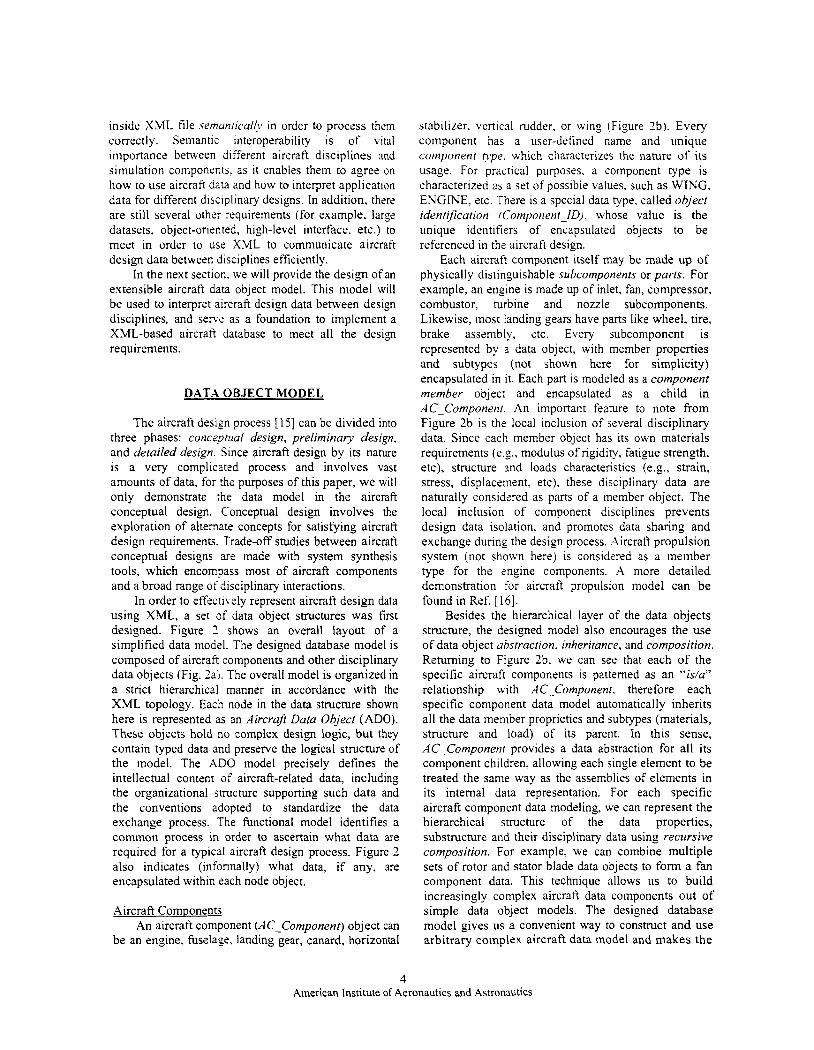
In order to effectively represent aircraft design data using XML, a set of data object structures was first designed. Figure 2 shows an overall layout of a simplified data model. The designed database model is composed of aircraft components and other disciplinary data objects (Fig. ’ai. The overall model is organized in a strict hierarchical manner in accordance with the XML topology. Each node in the data structure shown here is represented as an Aircrafl Data Object (ADO). These objects hold no complex design logic, but they contain typed data and preserve the logical structure of the model. The ADO model precisely defines the intellectual content of aircraft-related data, including the organizational structure supporting such data and the conventions adopted to standardize the data exchange process. The functional model identifies a common process in order to ascertain what data are required for a typical aircraft design process. Figure 2 also indicates (informally) what data, if any, are encapsulated within tach node object.
Aircraft Components An aircraft component (AC-Component) object can
be an engine, fuselage, landing gear, canard, horizontal
stabilizer, vertical rudder, or wing (Figure 2b). Every component has a user-defined name and unique Component Qpe. which characterizes the nature of its usage. For practical purposes, a Component type is characterized as a set of possible values, such as WING. ENGINE. etc. There is a special data type. called object identification tComponent-ID), whose value is the unique identifiers of encapsulated objects to be referenced in the aircraft design.
Each aircraft component itself may be made up of physically distinguishable subcomponents or parts. For example, an engine is made up of inlet, fan, compressor, combustor, turbine and nozzle subcomponents. Likewise, most landing gears have parts like wheel, tire, brake assembly, etc. Every subcomponent is represented by a data object, with member properties and subtypes (not shown here for simplicity) encapsulated in it. Each part is modeled as a component member object and encapsulated as a child in AC-Component. An important feature to note from Figure 2b is the local inclusion of several disciplinary data. Since each member object has its own materials requirements (e.g., modulus of rigidity, fatigue strength. etc), structure and loads characteristics (e.g., strain, stress, displacement, etc), these disciplinary data are naturally considered as parts of a member object. The local inclusion of component disciplines prevents design data isolation. and promotes data sharing and exchange during the design process. Aircraft propulsion system (not shown here) is considered as a member type for the engine components. A more detailed demonstration for aircraft propulsion model can be found in Ref. [ 161.
Besides the hierarchical layer of the data objects structure, the designed model also encourages the use of data object abstraction, inheritance, and composition. Returning to Figure 2b, we can see that each of the specific aircraft components is patterned as an “is/u” relationship with AC-Component. therefore each specific component data model automatically inherits all the data member proprieties and subtypes (materials, structure and load) of its parent. In this sense, AC-Component provides a data abstraction for all its component children, allowing each single element to be treated the same way as the assemblies of elements in its internal data representation. For each specific aircraft component data modeling, we can represent the hierarchical structure of the data properties, substructure and their disciplinary data using recursive composition. For example, we can combine multiple sets of rotor and stator blade data objects to form a fan component data. This technique allows us to build increasingly complex aircraft data Components out of simple data object models. The designed database model gives us a convenient way to construct and use arbitrary complex aircraft data model and makes the
4 American Institute of Aeronautics and Astronautics
ADO MODEL A
4C COMPONENT
C CUPONENT-NAME C SMPONENT-TYPE
m AC-COMPONENT
MATERIALS I V
m GLOBAL DISCIPLINES
.---TENSOR.STRENGTH :2MPRESS_YIELD -EUS LEY EL0 EeUIR_iROP.LMIT 3 4 A R - Y ELRSTREN Z r C W - Y ELD.POINT S&AR.bTL_STRENGTH S T C-'A00 I.IOD-RG L X Y =rTGU€_STRENGTH 3XROSON-RESIST '?ACTURE_TOUGHNES I9ESS. HTEN-COEFF :?ACK_GROWTH.RATE -3PERATURE '-ERMAL.EXPAN.COEFF
(a) Top level children of ADO model
1 GEAR H . STABILIZER
TI.]. ... ... .... ....
ENGINE COM Em GEOMETRY ck
WEIGHT-TOTAL '%' STRUCTURE-LOAD
EPS-X-STRAIN EPSY-STRAIN €PSI-STRAIN F-X-FORCE F-Y-FORCE F-2-FORCE M-X-MOMENT M-Y-MOMENT MI-MOMENT THETA-X-ROTATION THETA-Y-ROTATION THETA_Z.ROTATION U_X_DEFLECTION U-Y-DEFLECTION Y_Z_MFLECTION S.X_SHEAR S-Y-SHEAR S-Z-SHEAR
(b) Aircraft components data object model
WEIGHT
MISSION.WGT
AERODYNAMICS
I 1 1 -
4 FUEL.SYS.WGT 3 1 I (c) GlobalDisciplines data object model
Figure 2. Aircraft data object model
5 American Institute of Aeronautics and Astronautics
Lc__7 ROLL-PITCHJAW
model totally cxtcnsible for future enhanccments.
Geometrv Modeling Component geometry modeling is somewhat
unique in aircraft design. All disciplines share the same geometry. Strong interactions benveen the disciplines are very common and complicated. For example. during operation, the geometry of a flexible structure (e.g.. wing) may change due to the aeroelastic effects. Geometry modeling must, therefore. be accurate and suitable for various disciplines (e.g. deflection and load). For a multidisciplinary optimization problem, the application must also use a consistent parameterization across all disciplines. Thus, an application requires a common geometry dataset that can be manipulated and shared among various disciplines [ 171.
STEP Application Protocol AP 203 - Configuration Controlled 3D Designs of Mechanical Parts and Assemblies [18] - is a set of standards that defines the CAD geometry, topology. and configuration management data of solid models for mechanical parts. AP203 supports wireframe. surfaces, solids, configuration management, and assemblies. The STEP modelers have undertaken the very difficult job of defining mappings between the different representations of the same information. For example, a curve on the surface of fuselage can be represented as a B-spline, as a list of curve segments. or as NURBs. In our aircraft database, a placeholder has been designed to support various aircraft components’ geometry disciplinary data that conform to the STEP-based model. Because different components normally have very different geometry requirements. the geometry disciplinary data are considered local to every concrete component. Different fidelity geometry models can be chosen for use in the design process.
Global DisciDlines Other disciplinary data, such as stability and
control, aerodynamic, performance. cost, and weight data, are currently modeled as global objects (and grouped together as GlobalDisciplines) of the aircraft database (Figure 2c). This seems a little unnatural, however, these calculations have been traditionally grouped by discipline in aircraft design, and they probably will continue to be associated in this manner for some time to come. The relationship between these disciplinary data and aircraft database is also modeled as parent to child. For example. one of the relative important design parameters on the conceptual vehicle design is system performance. This disciplinary category in our design is currently made up of different criteria data objects, such as distance, speeds, limits, measures, etc., as shown in Figure 9c. The figure also gives the sampIe data that may be included in the discipline. New data will be added in as the data object
model evolves in thc future.
SCHEMA DESIGS
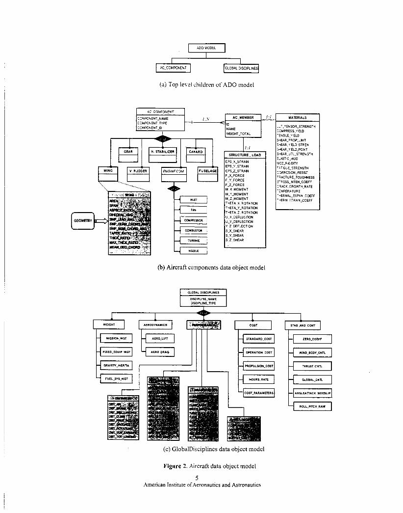
Aircraft Schema establish25 a bridge between XML-based description of a k a 3 data and the ADO model. A set of aircraft Schemz has been designed in XML Schema language thar specifies how the constituents of the ADO objez are mapped to an underlying XML structure. It associates each piece of information defined in ADO to a ?recise location in the XML structure.
Each aircraft data object 2efined in ADO is mapped to one or more nodes. For the most part, the aircraft Schema closely f 0 l l O t i - j the ADO model. Aircraft-schema file must be ADO-compliant in order for other applications to be abk ;o properly interpret aircraft data. This is particularly nportant when trying to transfer data between difzent disciplines and different storage models. as the:: must be agreed-upon data structure and syntax for iifferent systems to understand each other. The rules in ADO model will guarantee that the schema descr,srion of aircraft data is syntactically correct and follows :he grammar defined within it. An important feature of rhe ADO data model is the hierarchical structure. w k c h allows the aircraft data file to be structured as a roord directed graph, so it is necessary to map the directed s a p h of aircraft data in XML onto a tree of aircraft da:: objects specified ic ADO. However, when a given 3:ece of information is listed as being “under” a node. :here are actually two possibilities: the information can be stored as data in the current node, or it can be srored as data under a separate child node. The aiicraft schema also determines which of these two possibilities are best for each situation.
An example of aircrafi schema design is demonstrated in Figure 3. Based c7n the ADO model, an aircraft database model incluics several kinds of component data objects (such as b h g . Fuselage etc.), which can be contained in an aircraft, and a GobalDisciplines data object. To create aircraft component constructs, we stan by creating a basic
type7 aircraft component complex Aircraf tComponent-t, which contains a single AircraftMember ekment. An .l.:rzraftMember iS
constrained by its complexType .l.:rzzaftMenber-t, where AircraftMember-: irjelf contains Name Totalweight, Materials, 2nd SzructureLoad elements, and in turn, are constrained by their corresponding built-in string ppe. double type and similarly-defined complexTypes separately.
An aircraft component also contains a set of desired data attributes - componentType. name. identification - that are encapsulated in the AircrqfiCoinponent object.
6 American Institute of Aeronautics and Astronautics
c'k-i :yrc.or=' ' ;-"> <xsd.scherna ir:c?.:-es;a: ;='http://mernst ni.utoledo eduiaircraft'
1- -s='http.//rnemst ni.UtOied0 eddaircraft' w . w 3 org12001/XMLScherna'
-='materials.xsd" .> =%uctureload.xsd" >
<xsd.cornplexType -a~.d='AircraflComponent_t"> <xsd:sequence>
<xsd:element -aTa="AircraflMember' .:pe='AircraflMember_t" laxCcc-ij='unbounded"is
</xsd:sequence> <xsd:attributeGrouo ,4-"CornponentAttributes?s
</xsd:complexType>
<xsd:attnbuleGroup -3rE='ComponentAttnbules'> <wsd.attribute -arre='cornponentType" ,se='requred">
<xsd:sirnpleType>
</xsd.simpleType> </xsd:aflribute> <xsd attribute -are='narne' -~e="xsd:stnng" 2j+="required'/s <xsd.attribute -~r='idetificabon" 'ipe='xsd:ID' .se="required'!>
<ixsd:attributeGroup>
<xsd:complexType . -are=' AircraflMember -I">
<xsd:element -a-+StructureLoad' ':.:e="StNCtureLoad-t" 9 </xsd.sequence> <rsd:attribute -arc='rnernberlD" '!,pe="xsd:ID".'>
</xsd:complexType>
<xsd:complexType -aw= 'Wingt"> <xsd:complexContent>
<xsd:extension ~.3s.="AircraflComponent_t">
<lxsd:extension> <ixsd:cornpiexCon:en:>
<xsd:element ?rre='Aircraft'>
<!xsd.complexType>
<xsd:complexType> < xsd:sequence>
s are ;ei,:ec -era -> <xsd:element -a-.="GlobalDisciplines'
.I :;.="GlobalDisciplines_t'i> <ixsd:sequence>
</xsd:complexType> </xsd:element>
</xsd:schema>
Figure 3. A sample aircraft schema
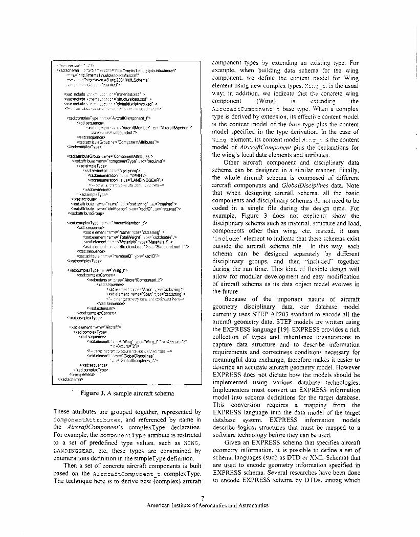
These attributes are grouped together, represented by ComponentAttribures, and referenced by name in the AircraftComponent's complexType declaration. For example, the componentType attribute is restricted to a set of predefined type values. such as WING, LANDINGGEAR, etc, these types are constrained by enumerations definition in the simpleType definition.
Then a set of concrete aircraft components is built based on the AircraftComponent-t complexType. The technique here is to derive new (complex) aircraft
componcnt types by extending an existing type. For example, when building data schema for the wing component. we define the content model for Wing element using new complex types. :I:.?-:. in the usual Lvay: in addition, we indicate that the concrete wing component (Wing) is extending the ~ircraftcomponent-~ base type. When a complex F p e is derived by extension, its effective content model is the content model of the base type plus the content model specified in the type derivation. In the case of x i n g element, its content model 5~:r;-: is the content model of AircrafiComponenf plus the declarations for the wing's local data elements and attributes.
Other aircraft component and disciplinary data schema can be designed in a similar manner. Finally, the whole aircraft schema is composed of different aircraft components and GlobalDisciplines data. Note that when designing aircraft schema. all the basic components and disciplinary schemas do not need to be coded in a single file during the design time. For example, Figure 3 does not explicitly show the disciplinary schema such as material. stmcmre and load, components other than wing, etc. instead. it uses ‘include' element to indicate that these schemas exist outside the aircraft schema file. In this way, each schema can be designed separately by different disciplinary groups, and then "included" together during the run time. This kind of flexible design will allow for modular development and easy modification of aircraft schema as its data object model evolves in the future.
Because of the important nature of aircraft geometry disciplinary data. our database model currently uses STEP AP203 standard to encode all the aircraft geometry data. STEP models are n-ritten using the EXPRESS language [19]. EXPRESS provides a rich collection of types and inheritance organizations to capture data structure and to describe information requirements and correctness conditions necessary for meaningful data exchange, therefore makss it easier to describe an accurate aircraft geometry model. However EXPRESS does not dictate how the models should be implemented using various database technologies. Implementers must convert an EXPRESS information model into schema definitions for the target database. This conversion requires a mapping from the EXPRESS language into the data model of the target database system. EXPRESS information models describe logical structures that must be mapped to a software technology before they can be used.
Given an EXPRESS schema that specifies aircraft geometry information, it is possible to define a set of schema languages (such as DTD or XML-Schema) that are used to encode geometry information specified in EXPRESS schema. Several researches have been done to encode EXPRESS schema by DTDs. among which
7 American Institute of Aeronautics and Astronautics
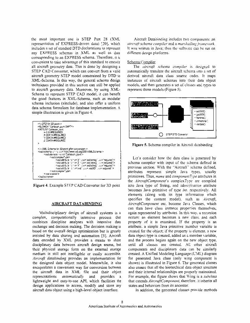
the most important one is STEP Part 18 (XML representation of EXPRESS-driven data) [ZO], which includes a set of standard DTD declarations to represent any EXPRESS schemas in XML as well as data corresponding to an EXPRESS schema. Therefore, it IS
convenient to take advantage of this standard to encode all aircraft geometry data. This is done by designing a STEP CAD Conventer, which can convert from a valid aircraft geometry STEP model constrained by DTD to XML-Schema. In this way, the general schema design techniques provided in this section can still be applied to aircraft geometry data. Moreover, by using XML- Schema to represent STEP CAD model, it can benefit the good features in XML-Schema, such as modular schema inclusion (xinclude), and also offer a uniform data schema formalism for database implementation. A simple illustration is given in Figure 4.
<'-DTD for 3D point--> <[ELEMENT Cartesian_po~nr EUPTY, C'ATTLIST Canestan tom1
x-ad ID #REQUIRED X CDATA :REQUIRED Y CDATA #REQUIRED 2 CDATA $REQUIRED
>
<'-XMl Schema for 3D-point after convemon--> cxsd:schema <,- - 5 <jz= h~p:/lwww.w3.org/200liXMLSchema >
<xsd:element -..-?='Cattesian30int"> <xsd:complexType>
<xsd:annbule " i - + X 'p='xsd:string 2ia='required''/> <xsd:aflnbule -a-?= 2 ',.;e='xsd:string .s?='required":> <xsd:aflnbute -'2-f= Y 'me= xsd:sb.ing ~a='required"'> <xsd:aflnbute -?-e= x-id .)pe='xsd:ID .sd= required :>
<, xsd'compIex>fpe> <:xsd:element>
<ixsd.schema>
Figure 4. Example STEP CAD Converter for 3D point
AIRCRAFT DATABINDING
Multidisciplinary design of aircraft systems is a complex, computationally intensive process that combines discipline analyses with intensive data exchange and decision making. The decision making is based on the overall design optimization but is greatly assisted by data sharing and automation [SI. Aircraft data encoded by XML provides a means to share disciplinary data between aircraft design teams, but their physical storage form on the external storage medium is still not intelligible or easily accessible. Aircraft databinding provides an implementation for the designed data object model. Meanwhile, it also encapsulates a convenient way for conversion between the aircraft data in XML file and their object representations automatically and provides a lightweight and easy-to-use API, which facilities the design applications to access, modify and store any aircraft data object using a high-level object interface.
Aircraft Databinding includes tWo components: an uircruji schema conipiler and a tnur.shul1ing /runiework. I t was written in Java: thus the software can be run on different design platforms.
Schema Compiler The uircrujt .schemu compiler is designed to
automatically translate the aircraft schema into a set of derived aircraft data class source codes. I t maps instances of aircraft schemas into their data object models, and then generates a set of classes and types to represent those models (Figure 5)
0 STEP DTD Converter I ~ ___ ~~
Figure 5. Schema compiler in Aircraft databinding
Let's consider how the data class is generated by schema compiler with input of the schema defined in previous section. With the "Aircraft" schema defined, attributes represent simple Java types. usually primitives. Thus, name and componenr~~pe attributes in the AircruftComponent's complexTye are compiled into Java type of String, and idenrjficarion attribute becomes Java primitive of type inr. respectively. All elements (along with its type information which specifies the content model), such as .4ircrajl, Aircl-ajKomponent etc, become Java Classes. which can then have class instance properties themselves, again represented by attributes. In this way. a recursion occurs: an element becomes a new class, and each property of it is examined. If the property is an attribute, a simple Java primitive member variable is created for the object; if the property is element. a new data object type is created, added as a member variable, and the process begins again on the new object type, until all classes are created. All other aircraft components and disciplinary data can be similarly created. A Unified Modeling Language (UML) diagram for generated Java class (only wing component is shown) is illustrated in Figure 6. The generated classes also ensure that all the hierarchical data object structure and their internal relationships are properly maintained. For example, the figure shows that LVing is a subclass that extends AircrajtCornponent, therefore. it inherits all states and behaviors from its ancestor.
In addition, the generated classes provide methods
8 American Institute of Aeronautics and Astronautics
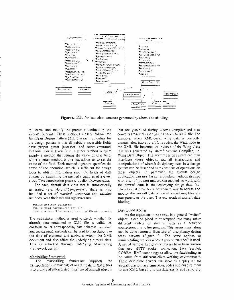
1
Figure 6. LTfL for Data class structure generated by aircraft databixding
to access and modify the properties defined in the aircraft Schema. These methods closely follow the JavaBean Design Pattern [21]. The main guideline for the design pattern is that all publicly accessible fields have proper getter (accessor) and setter (mutator) methods. For a given field. a gener method is quite simply a method that returns the value of that field, while a setter method is one that allows us to set the value of the field. Each method signature specifies the name of the operation, Lvhich is sufficient for design tools to obtain information about the fields of data classes by examining the method Signatures of a given class. This examination process is zalled Introspection.
For each aircraft data class that is automatically generated (e.g. AircrafrComponent) , there is also included a set of marshal. zrnniarshal and validate methods, with their method signatures like:
p ~ b l i c boolean vali5ateO
F.Jb;ic AircraftConFone:: ur,rsrsha? (Reader reader) F J b l l c vold marshal (iJz::tr c
The validate method is used to check whether the aircraft data contained in XML file is valid. i.e. conform to its corresponding data schema; marshal and unmarshal methods can be used to map directly to the data of elements and attributss within the XML document and also affect the underlying aircraft data. This is achieved through underlying Marshalling Framework design.
Marshalling Framework The marshalling frameLvork supports the
transportation (unmarshal) of aircraft data in XML files into graphs of interrelated instances of aircraft objects
that are generated during <;:lema complier and also converts (marshal) such grz??.s back into XML file. For example, when XML-bas:: wing data is correctly unmarshaled into aircraft JL..-L codes. the Wing node in the XML file becomes ar, ::stance of the Wing class that was generated by a i r z 5 Schema Compiler, i.e. Wing Data Object. The a i r zx l design system can then interfaces those objects. 2nd all interactions and manipulations of aircraft 2:s;iplinary data in a design system can be described as ::.vocations of operations on those objects. In partiz2L.r. the aircraft design application can use the corxqonding methods devised with a set of mutator and ai';?sor methods to work with the aircraft data in the urtkrlying design data file. Therefore, it provides a comenient way to access and modify the aircraft data n-tere all underlying files are transparent to the user. The end result is aircraft data binding.
Distributed Access As the argument in ~.zr:?.a: is a general "writer"
object, it can be piped to a; wrapped into many other different writers or streams. such as a network connection, or another progrzm. This means marshaling can be done remotely f r o r iircraft disciplinary design team servers (Figure - 1 . The same applies to unmarshaling process whe:: 3 general "Reader" is used. A set of sample disciplinap drivers have been written that use HTTP socket annection, Java Servlet, CORBA, RMI technology 13 allow the databinding to be called from different client working environments. These discipline drivers can serve as a 'plug-in' for aircraft disciplinary simulation codes and enables them to use XML-based aircraft data easily and remotely.
9 American Institute of Aeronautics and Astronautics
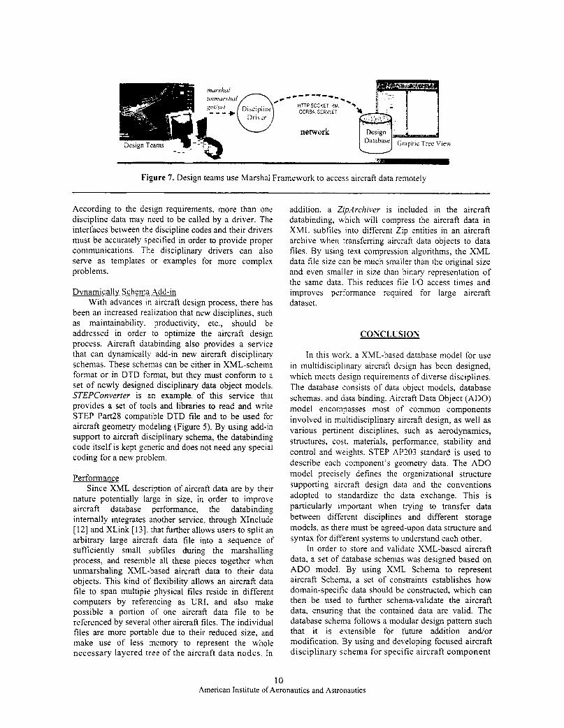
Graphic Tree Vie\+
Figure 7. Design teams use Marshal Framework to access aircraft data remotely
According to the design requirements. more than one discipline data may need to be called by a driver. The interfaces between the discipline codes and their drivers must be accurately specified in order to provide proper communications. The disciplinary drivers can also serve as templates or examples for more complex problems.
Dvnamicallv Schema .Add-in With advances in aircraft design process, there has
been an increased realization that new disciplines, such as maintainability. productivity, etc., should be addressed in order to optimize the aircraft design process. Aircraft databinding also provides a service that can dynamically add-in new aircraft disciplinary schemas. These schernas can be either in XML-schema format or in DTD format, but they must conform to a set of newly designed disciplinary data object models. STEPConverter is an example of this service that provides a set of tools and libraries to read and w i t t STEP Part28 compatible DTD file and to be used for aircraft geometry modeling (Figure 5) . By using add-in support to aircraft disciplinary schema, the databinding code itself is kept generic and does not need any special coding for a new problem.
Performance Since XML description of aircraft data are by their
nature potentially large in size, in order to improve aircraft database performance, the databinding internally integrates another service, through XInclude [ 121 and XLink [13]. that further allows users to split an arbitrary large aircraft data file into a sequence of sufficiently small subfiles during the marshalling process, and resemble all these pieces together when unmarshaling XML-based aircraft data to their data objects. This kind of flexibility allows an aircraft data file to span multiple physical files reside in different computers by referencing as URI, and also make possible a portion of one aircraft data file to be referenced by several other aircraft tiles. The individual files are more portable due to their reduced size, and make use of less memory to represent the whole necessary layered tree of the aircraft data nodes. In
addition. a Ziptrchiver is included in the aircraft databinding, which will compress the aircraft data in XML subfiles into different Zip entities in an aircraft archive when transferring aircraft data objects to data tiles. By using text compression algorithms, the XML data file size can be much smaller than the original size and even smaller in size than binary representation of the same data. This reduces file I/O access times and improves performance required for large aircraft dataset.
CONCLUSION
In this work. a XML-based database model for use in multidisciplinary aircraft design has been designed. which meets design requirements of diverse disciplines. The database consists of data object models, database schemas. and data binding. .4ircraft Data Object (ADO) model encompasses most of common components involved in multidisciplinary aircraft design, as well as various pertinent disciplines. such as aerodynamics, structures, cost. materials, performance, stability and control and weights. STEP AP203 standard is used to describe each component’s geometry data. The ADO model precisely defines the organizational structure supporting aircraft design data and the conventions adopted to standardize the data exchange. This is particularly important when trying to transfer data between different disciplines and different storage models. as there must be agreed-upon data structure and syntax for different systems to understand each other.
In order to store and validate XML-based aircraft data, a set of database schemas was designed based on ADO model. By using XML Schema to represent aircraft Schema, a set of constraints establishes how domain-specific data should be constructed, which can then be used to further schema-validate the aircraft data, ensuring that the contained data are valid. The database schema follows a modular design pattern such that it is extensible for future addition and/or modification. By using and developing focused aircraft disciplinary schema for specific aircraft component
10 American Institute of Aeronautics and Astronautics
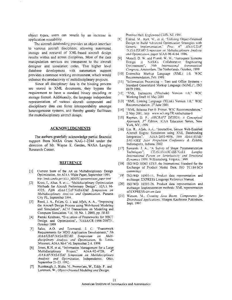
object types, users can jenefit by an increase in application reusability.
The aircraft databinding provides an object interface to various aircraft disci?lines, allowing autotnated storage and retrieval of XML-based aircraft design results within and across iisciplines. Most o f the data manipulation services are transparent to the aircraft designer and simulation codes. This higher level database development Lvith automation support provides a common working environment, which would enhance the productivity of multidisciplinary projects.
Since all disciplinary data in the binding process are stored in XML documents, they bypass the requirement to have a standard binary encoding or storage format. Additionally, the language independent representation of various aircraft component and disciplinary data can f0jt:r interoperability amongst heterogeneous systems, ar,d thereby greatly facilitates the multidisciplinary aircraft design.
ACKNOWLEDGMENTS
The authors gratefully acknowledge partial financial support from NASA Grant NAG-1-2244 under the direction of Mr. Wayne K. Gerdes, NASA Langley Research Center.
REFERENCE
Current State of the .Art on Multidisciplinary Design Optimization, An A1X.A White Paper, September 1991.
Kroo. I., Altus. S. et 3:. "Multidisciplinary Optimization Methods for Aircraft Treliminary Design", A1A.A 94- 4325, Fifth AIAAI LT.-1F/.VASA/OAI Svmposiirm on Multidisciplinan Ano.>;sis and Optimization, Panama City FL, September 1391. Reed, J. A.. Follen. G. J. and Afjeh, A. A.. "Improving the Aircraft Design Process using Web-based Modeling and Simulation". ACJI Transactions on Modeling and Computer Simulation. 1-01. 10, No. 1,2000. pp. 58-83 Ramki Krishnan, "E\ ahation of Frameworks for HSCT Design and Optimization", NASNCR- 1998-20873 1. October 1998 Salas, A.O. and Townsend. J. C. "Framework Requirements for MDO Application Development." 7th AIAA/USAF~~ASA/ISS.~lO Svmposium on .Cfulti- disciplinary Analysis and Optimization. St. Louis. Missouri. AIAA 98-1-40. September 2-4, I998 Jones, K.H. et al. "Inionnation Management for a Large Multidisciplinary P:oject." AIAA-92-4720. +'Ih
AIAA/AF/NASA/OAI Srmposiirm on Miiltidisciplinay Ana!vsis and Optimization, Independence, Ohio, September 21-23. 1993. Rumbaugh, J.. Blaha. SI.. Premerlani, W., Eddy, F., and Lorensen, W., Object-Oriented Modeling and Design,
http:~/endo.sandiu.~o~ /AI.<: -41DOTC.~ponsorediorau~aper html
Prentice Hall. Englewood Cliffs. NJ. 1991. Eldrcd. M., Hart. LV., c't al. "Ltiliring Object-Oriented Design to Build ,lJ\anced Optimization Strategies with Generic Implementation." Pruc. 6'" . . I I .~II /LS~F ~.\'..IS.4/lSS.CIO St.mpo.srzrm on .~~irltidi.sciplinrt~ .-l nulJ,sis irnd Optimiztrrion. paper AIAA-96-4 161. 1996. Monell. D. W. and Piland. W. M., "Aerospace Systems Design in SXSA's Collaborative Engineering Environment". 50th lnterntitionul ;Istronuiitical Congress. Amsterdam. The Netherlands. October. 1999
[ I O ] Extensible Markup Language (XML) 1.0. W3C Recommendation. Feb. 1998
[ 1 I] "Information Processing -- Text and Office Systems - Standard Generalized Markup Language (SGML)", IS0 8879: 1986.
[ 121 "XML Inclusions (XInclude) Version 1 .O." W3C Working Draft 16 May 2001
[ 131 "XML Linking Language (XLink) Version 1.0." W3C Recommendation. 27 June 2001
[ 111 "XML Schema Part 0: Primer, W3C Recommendation." 2 May 200 1, http: www.w3.orgTR umlschema-0
[I51 Raymer. D. P.. .-IIRCR4FT DES1G.V: .4 Conceptiial Approach. 3'" Edition, AIAA Education Series, Kew York, NY. 1999
[ 161 Lin, R.. Afjeh. X.Z.. "Interactive. Secure Web-Enabled Aircraft Engine Simulation using XML Databinding Integration". AIAA-2002-4058. 38/17 AIAA/..IS.LE/ SAE/ASEE Joint Propulsion Conference & Exhibit. Indianapolis, Indiana. 2002
[ 171 Samareh. J. A, . "A Suney of Shape Parameterization Techniques". C E . . I S / , - I I . ~ A / I C , ~ S E I ~ ~ ~ S . ~ Langley International Forirni on .leroelasricih, and Stnrctirral Qnumics 1999. Williamsburg, Virginia. 1999
[18] ISO/WD I0303 STEP. the International Standard for the Exchange of Product Model Data. I S 0 TC181iSC-1 committee
[ 191 ISO/WD 10303-1 1. Product data representation and exchange: EXPRESS Language Reference Manual
[ lo] ISOiWD 10303-28. Product data representation and exchange: Implementation methods: XML representation of EXPRESS-driven data
[21] Watson. M.. Creating Java Beans: Components for Distributed ,4pplications. Morgon Kaufmann Publishers. Sept, 1997
[SI
[9]
11 American Institute of Aeronautics and Astronautics
AlAA 2002- 4058 I nteractive, Secure We b-ena bled Aircraft Engine Simulation Using XML Databinding Integration Risheng Lin and Abdollah A. Afjeh The University of Toledo Toledo, Ohio
38th AlAAlASMElSAElASEE Joint Propulsion Conference & Exhibit
Indianapolis, Indiana 7 - 10 July 2002
For permission to copy or to republish, contact the copyright owner named on the first page. For AIM-held copyright, write to A I M Permissions Department,
1801 Alexander Bell Drive, Suite 500, Reston, VA, 201914344.
INTERACTIVE, SECURE WEB-ENABLED AIRCRAFT ENGINE SIMULATION USING XML DATABINDING INTEGRATION
Risheng Lin' and Xbdollah A. Afjeh' The University of Toledo 7801 West Bancroft Street Toledo. Ohio 13606. USA
ABSTRACT
This paper discusses the detailed design of an XML databinding framework for aircraft engine simulation. The framework provides an object interface to access and use engine data. while at the same time preserving the meaning of the original data. The Language independent representation of engine component data enables users to move around XML data using HTTP through disparate networks. The application of this framework is demonstrated via a web-based turbofan propulsion system simulation using the World Wide Web (WWW). A Java Servlet based web component architecture is used for rendering XML engine data into HTML format and dealing with input events from the user, which allows users to interact with simulation data from a web browser. The simulation data can also be saved to a local disk for archiving or to restart the simulation at a later time.
INTRODUCTION
Computer programs capable of simulating the operation of aircraft engines are useful tools that can help reduce the time, cost and risk of product design and development and facilitate learning about the complex interactions between jet engine components. However, the strongly-coupled nature of the components' flow physics and the large number of operating and design parameters needed for simulation of the aircraft engine system present a challenge to developers who aim at designing an easy-to-use and effective engine simulation program for users. Most of the aircraft engine simulation software currently available have limitations primarily in the presentation of the simulation input and output data, due to the use of text-based interfaces, and the lack of data validation methods. As a result, engine simulation results could be overwhelming and difficult to interpret without a
* Research Associate, Student Mcmber AIAA. Departmcnt of Mcchanicai. Industrial and Manufacturing Enginccring. E-mail: [email protected] t Professor and Chair, Departmcnt of Mechanical. Industrial and Manufacturing Enginccring. Mcmbcr AIAA. E-mall: [email protected] cdu Copyright 7 2002 by Rishcng Lin. Published by the Amcricon Institute of Aeronautics and Astronautics, Inc., with permission.
significant effort. Moreover, traditional sirnulation data are, in general, stored in proprietary data formats and constrained by hardware and operating system platform differences. Thus, developers are hicdered in their efforts to synthesize simulation data in their design unless a clearly defined and interoperable data interface exists. The bottlenecks caused by iata handling, heterogeneous computing enviroments and geographically separated design teams. continue to restrict the use of these tools [ l ] .
Web-based simulation, due to its accessibility, convenience and emphasis on collaborative composition of simulation models. distributed heterogeneous execution, and dynarr-ic multimedia documentation, has the potential to hriamentally alter the practice of simulation [ 2 ] . Presentl?. :he majority of work in web-based simulation has xntzred on re- implementation of existing distributed 2nd standalone simulation logics within Java Applets :?.-!I. Applets are quite popular because they are suppocd by common browsers and are safe to execute on ciient computers. However. with the whole simulation c c 2 iight(v-bozind to an Applet, it may take a long time for the rich engine simulation code to load within a clierT's browser. In addition, it is often not efficient to execute complicated simulation logic at the client side. ivhere a high performance computer is generally not available. Applets' security model, arguably one si its strengths, also creates obstacles for post-processiq of simulation data beyond what applets provide since it inhibits creation of data files on the host machine.
This paper describes a web-based sircraft engine simulation system, called X-Jgrs. through dynamic XML databinding framework which permits data communication with ease. XML [ 5 ] . due to its structured, platform and language independent, highly extensible and web-enabled nature. has rapidly become an emerging standard to represent data between diverse applications. XML can represent both structured and unstructured data, along with its rich descriptive delimiters. By using XML to represent engine data in high performance propulsion system simulation, it is possible to faithfully model the structural elements of a chosen component in an interoperable fashion that is natural in their simulation context. Since HTTP (Hyper Text Transfer Protocol) already s\pports transmission
1 American Institute of Aeronautics and Astronautics
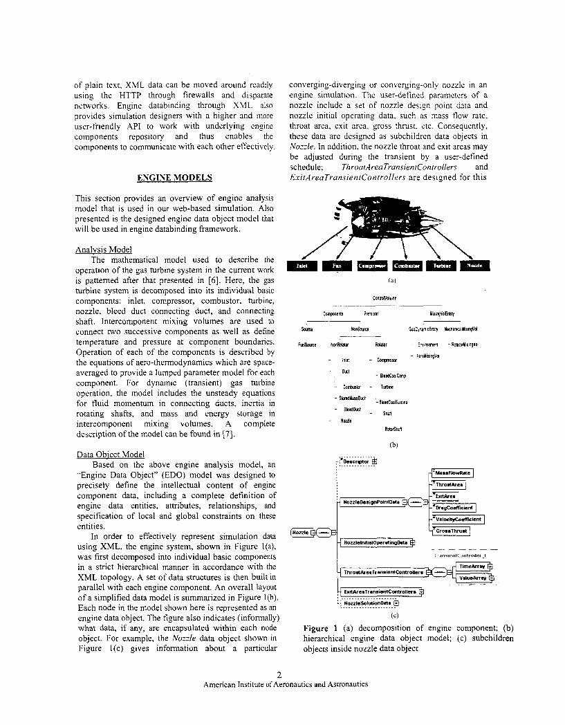
of plain text, XML data can be moved around readily using the HTTP through firewalls and disparate networks. Engine databinding through XML also provides simulation designers with a higher and more user-friendly API to work with underlying engine components repository and thus enables the components to communicate with each other effectively.
ENGINE MODELS
This section provides an overview of engine analysis model that is used in our web-based simulation. Also presented is the designed engine data object model that will be used in engine databinding framework.
Analysis Model The mathematical model used to describe the
operation of the gas turbine system in the current work is patterned after that presented in [ 6 ] . Here, the gas turbine system is decomposed into its individual basic components: inlet, compressor, combustor, turbine, nozzle, bleed duct connecting duct, and connecting shaft. Intercomponent mixing volumes are used to connect two successive components as well as define temperature and pressure at component boundaries. Operation of each of the components is described by the equations of aero-thermodynamics which are space- averaged to provide a lumped parameter model for each component. For dynamic (transient) gas turbine operation, the model includes the unsteady equations for fluid momentum in connecting ducts, inertia in rotating shafts, and mass and energy storage in intercomponent mixing volumes. A complete description of the model can be found in [7].
Data Obiect Model Based on the above engine analysis model, an
"Engine Data Object" (EDO) model was designed to precisely define the intellectual content of engine component data, including a complete definition of engine data entities, attributes, relationships, and specification of local and global constraints on these entities.
In order to effectively represent simulation data using XML, the engine system, shown in Figure l(a), was first decomposed into individual basic components in a strict hierarchical manner in accordance with the XML topology. A set of data structures is then built in parallel with each engine component. An overall layout of a simplified data model is summarized in Figure l(b). Each node in the model shown here is represented as an engine data object. The figure also indicates (informally) what data, if any, are encapsulated within each node object. For example, the N o d e data object shown in Figure l(c) gives information about a particular
converging-diverging or converging-only nozzle in an engine simulation. The user-defined parameters of a nozzle includc a set of nozzle design point data and nozzle initial operating data, such as mass flow rate, throat area, exit area. gross thrust. etc. Consequently, these data are designcd as subchildren data objects in Nozzle. In addition. the nozzle throat and exit areas may be adjusted during the transient by a user-defined schedule; ThroatAreaTransienrControllers and E.rit..lreaTransientControllers are designed for this
ConholVoluen
- Duct - EleedCwlCmp
r Cornburtor - Tuhne
L SloleduarrDuct
- BleedOuct - BleedcwlT*rbloc
- shin - Noule
- RotorShri?
(b) ,i_. .......... :'Descriptor a ..............
NozzleOesignPointDaia -
. .
4 ..................... i NozzleSolutionDais @ ..................... (C)
Figure 1 (a) decomposition of engine component; (b) hierarchical engine data object model; (c) subchildren objects inside nozzle data object
2 American Institute of Aeronautics and Astronautics
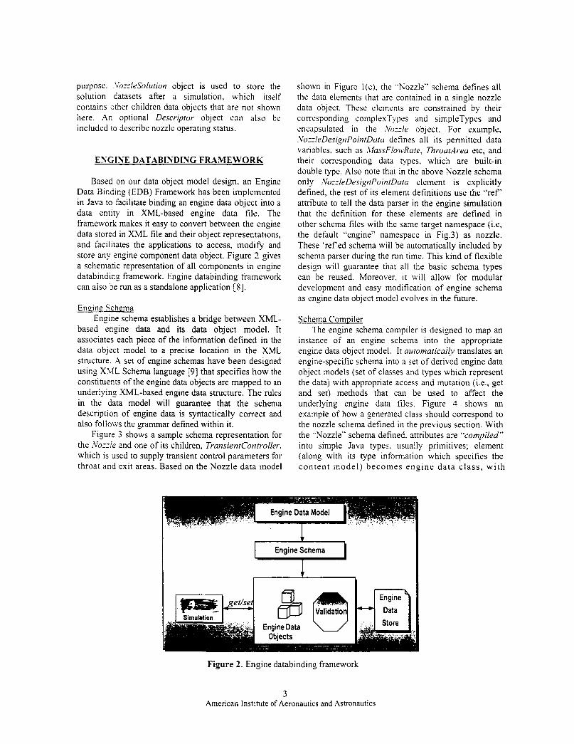
purpose. Lh-IeSolution object is used to store the solution datasets after a simulation, which itself contains other children data objects that are not shown here. An optional Descriptor object can also be included to describe nozzle operating status.
ESCINE DATABINDING FRAMEWORK
Based on our data object model design. an Engine Data Binding (EDB) Framework has been implemented in Java to facilitate binding an engine data object into a data entity in XML-based engine data file. The framework makes it easy to convert between the engine data stored in XML file and their object representations, and facilitates the applications to access, modify and store any engine component data object. Figure 2 gives a schematic representation of all components in engine databinding framework. Engine databinding framework can also be run as a standalone application [8].
Engine Schema Engine schema establishes a bridge between XML-
based engine data and its data object model. It associates each piece of the information defined in the data object model to a precise location in the XML structure. .A set of engine schemas have been designed using X\lL Schema language [9] that specifies how the constituents of the engine data objects are mapped to an underlying XML-based engine data structure. The rules in the data model will guarantee that the schema description of engine data is syntactically correct and also folloivs the grammar defined within it.
Figure 3 shows a sample schema representation for the .Voz:!e and one of its children, TransientController, which is used to supply transient control parameters for throat and exit areas. Based on the Nozzle data model
shown in Figure l(c), the “Nozzle” schema defines all the data elements that are contained in a single nozzle data object. These elements are constrained by their corresponding complexTypes and simpleTypes and encapsulated in the ~Vozzle object. For example. .VozzleDesi,SriPointDclltr defines all its permitted data variables. such as ,Clas.sFloivRuie, ThroatArea etc, and their corresponding data types. which are built-in double type. Also note that in the above Nozzle schema only ,VozleDesignPointData element is explicitly defined, the rest of its element definitions use the “ref’ attribute to tell the data parser in the engine simulation that the definition for these elements are defined in other schema files with the same target namespace (Le, the default “engine” namespace in Fig.3) as nozzle. These ‘ref ed schema will be automatically included by schema parser during the run time. This kind of flexible design will guarantee that all the basic schema types can be reused. Moreover. it will allow for modular development and easy modification of engine schema as engine data object model evolves in the future.
Schema Compiler The engine schema compiler is designed to map an
instance of an engine schema into the appropriate engine data object model. It aziiomatically translates an engine-specific schema into a set of derived engine data object models (set of classes and types which represent the data) with appropriate access and mutation (Le., get and set) methods that can be used to affect the underlying engine data files. Figure 4 shows an example of how a generated class should correspond to the nozzle schema defined in the previous section. With the “Nozzle” schema defined. attributes are “compiled” into simple Java types, usually primitives; element (along with its type information which specifies the conten t model) becomes engine da ta class, with
Engine Data Model
Engine Schema
I ,
Figure 2. Engine databinding framework
3 American Institute of Aeronautics and Astronautics
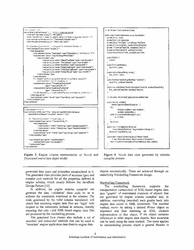
' y - , e r s G - j ' s ;'-s
sa scnema !arge!Naresoace=
:.,eng ne' eie.rentForrrDefajl:="qr;ai,fiec' vemn:" 2') r = TransientController xsd":> cxsd include s
<xsd-include s r = 'Descriptor.xsd":>
Cxsd complexType name='Voule-t"> <xsd.sequence>
<xsd element name='DescnptoC type="Descnptor-t" rninOccurs=*O"'> <xsd element name='NouleDesignPoinfData">
Cxsd cornplexT,pe> <xsd'aUr:cute name="MassFlowRate" type="xsd:double"P cxsd.an: cute name="ThroatArea" type="xsd:double" > cxsd anrcute name="ExitArea" type="xsd:double"i> Cxsd anntute name="DragCoefficient" type="xsd:double"b <xsd .an rn te name="VelocityCoefcient" type="xsd:double"l> <xsd-anrcute name="GrossThrust" type="xsd:double"'>
4 x s d cornplexTjpe> <ixsd:element> <I-- NozzlelnitralC,-s~~ringDala element IS simiianly oesigned
and ommilfez -$'e 'or simplicity--> <xsd'element name= ThroatAreaTransCntl"
type='TransientCntI-t"b <xsd.element name='ExitAreaTransCntl"
type='TransientCntl-t"l> <!-AN NorzieSc'; 7-Dara elements and ornmitted ior s !~p l iC ! r j ' - -~
</xsd'sequence> <xsd'attribute name='Vame" type="xsd.string" use="requiredl>
<lxsd.complexType> lxsd schema>
'xml version=": C"7s csd'schema xmlns xsd="hnp ."ww.w3.org/2001/XMLSchema"
elementForrnDeiault="quairfied" version="l .O">
< I - - TransierirCor:rroils~ r r -oexType --> <xsd:complexType narre= TransientCntl-t">
<xsdsequence> <xsd elemerr -ame="TimeArray" type="doubleDatalist"i> <xsd elemer l -ame="ValueArray" type="doubIeDatalist":>
4 x s d sequence> <xsd:attribute nane='name' type="xsd:string" use="optional"i>
<lxsd.complexType>
<xsd,simpleType name='$oubleDatalist">
<Ixsd:simpleType> <xsd:list itemType='xsd:double'*l>
xsd-schema>
I- all the Java -,port statements here
iublic class F:cu:e implements java.io Senalizable { private Str1r.G _lame; pnvate Cescrstor descriptor; private Ces,q?ointData _nouleDesignPointCa': pnvate In!tC:eratingData _noulelnit05eratingC3ia; pnvate Thrca~kaTransCntl -throatAreaTransCn:l: pnvate ExitAreaTransCntl _exitAreaTransCntl: pnvate NozzeSolutionData -nouleSolbtionData.
public Nowe!) ( super();
public StnnG setName() ( return this -name;
1
1
public void serName(Stnng name) ( this.-nar;e =name;
public ExitAreaTransCntl getExitAreaTransCntlli {
i return in's -exiIAreaTransCntl;
public doid setExitAreaTransCntl(ExitAreaTransCntl exitAreaTransCntl) (
1 :his _exitAreaTransCntl = exitAreairansCntl,
I / - the same .wth ail other rypes and are ornineo here
public woiean validate() throws ~ngineValidationExceprion { i
'lalidator validator = new Validatori;: ialidator.validate(this); )
catch iE'SineValidationException vex) { rer.:n ialse:
return :?de;
1 puolic VO!G -arshalfiava.io.Writer out)
thrcws MarshalException, EngineValida:,onException ( Marsha,,er marshal(this. out);
} public sta:c houle bnmarshalijava.~o.i?eader ?eader)
!hrows LlarshalExcepfion. EngineVa1ida;onExceDtion { return i~uouie)Unmarshaller.unmarshal(Nou.e.class, xader):
!
Figure 3. Engine schema representation of Nozzle and TransientControl data object model
Figure 4. Yozzle data class generated by schema compiler process
generated data types and properties encapsulated in it. The generated class provides pairs of accessor (get) and mutator (set) methods for all the properties defined in
objects automatically. These are achieved through an underlying Marshalling Framework design.
engine schema, which closely follows the JavaBean Design Pattern [ 101.
In addition, the engine schema compiler can generate the data 'validation' class code so as to enforce the constraints expressed in the schema. The code generated by the valid schema translation will check that incoming engine data files are 'legal' with respect to the constraints defined in schema, thereby ensuring that only valid XML-based engine data files are produced by the marshalling process.
The generated Java classes also include a set of marshal, and iinmarshal methods that can be used to "translate" engine application data f r o d t o engine data
Marshalling Framework The marshalling framework supports the
transportation (immarshal) of XML-based engine data into "graphs" of interrelated instances of objects that are generated by engine schema complier and, in addition, converting (marshal) such graphs back into engine data stored in XML documents. The marshal method works by taking a desired Writer object as argument and then returning an XML element representation of that object. If the object contains references to other engine data objects, then recursion can be used. using the same method. The same applies to unmarshaling process where a general Reader is
4 American Institute of Aeronautics and Astronautics
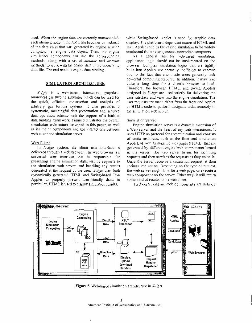
used. When the engine data are correctly unmarshakd, each element node in the XML file becomes an instance of the data class that was generated by engine schema compiler, i.e. engine data object. Then. the engine simulation components can use the corresporiding methods, along with a set of miitator and occesor methods, to work with the engine data in the underlying data file. The end result is engine data binding.
SIMULATION ARCHITECTURE
X-Jgts is a web-based. interactive, graphical, numerical gas turbine simulator which can be used for the quick, efficient construction and analysis of arbitrary gas turbine systems. It also provides a systematic, meaningful data presentation and secured data operation scheme with the support of a built-in data binding framework. Figure 5 illustrates the overall simulation architecture described in this paper, as well as its major components and the interactions between web client and simulation server.
Web Client In X-Jgts system, the client user interface is
delivered through a web browser. The web browser is a universal user interface that is responsible for presenting engine simulation data, issuing requests to the simulation web sener. and handling any results generated at the request of the user. X-Jgrs uses both dynamically generated HTML and Swing-based Java Applet to properly present user-friendly data; in particular, HTML is used to display simulation results,
while Swing-based Applet is used for graphic data display. The platform-independent nature of HTML and Java Applet enables the mgine simulation to be widely conducted from heterogeneous, networked computers.
A s a general rule for web-based simulation, application logic should not be implemented on the browser. Complex simulation logics that are tightly built into Applets are normally inefficient to execute due to the fact that client side users generally lack powerful computing resource. In addition, it may take quite a long time for a client’s browser to load. Therefore, the browser. HTML, and Swing Applets designed in X-Jgts are used strictly for delivering the user interface and view into the engine simulation. The user requests are made either from the front-end Applet or HTML code to perform designate tasks remotely in the simulation web sener.
Simulation Server Engine simulation sener is a dynamic extension of
a Web server and the heart of any web interactions. It uses HTTP as protocol for communication and consists of static resources, such as the front end simulation Applet, as well as dynamic web pages (HTML) that are generated by different mgine web components hosted in the server. The wzb server listens for incoming requests and then senices the requests as they come in. Once the server receiles a simulation request, it then springs into action. Depending on the type of request, the web server might look for a web page, or execute a web component on the si!n er. Either lvay, it will return some kind of results to the web client.
In X-Jgts, engine web components are sets o f
Engine Simulation Computing
Databinding I Engine I Result
Conf.
Downloa Data
Figure 5. Web-based simulation architecture in X-Jgts
5 American Institute of Aeronautics and Astronautics
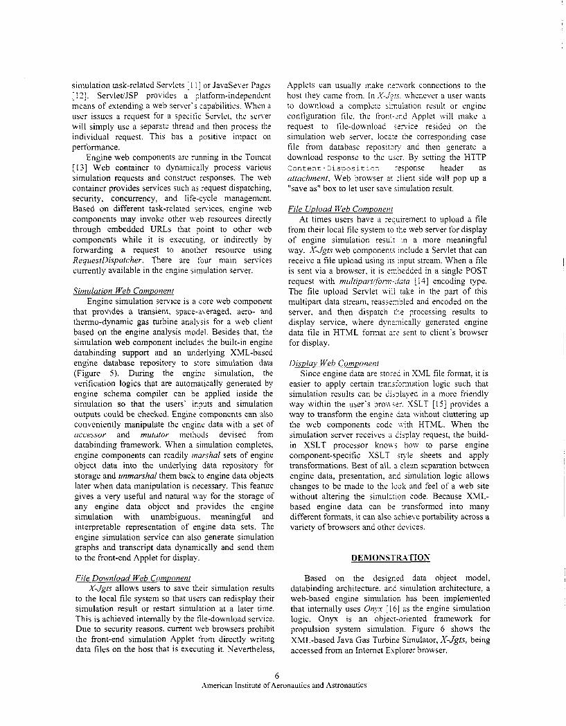
simulation task-related Servlets [ 1 11 or JavaSevsr Pages [ I ? ] . ServletiJSP provides a platform-independent means of extending a web server’s capabilities. When a user issues a request for a specitic Servlet. the server will simply use a separate thread and then process the individual request. This has a positive impact on performance.
Engine web components are running in the Tomcat [ I33 Web container to dynamically process various simulation requests and construct responses. The web container provides services such as request dispatching, security, concurrency, and life-cycle management. Based on different task-related services, engine web components may invoke other web resources directly through embedded URLs that point to other web components while it is executing. or indirectly by forwarding a request to another resource using RequestDispatcher. There are four main services currently available in the engine simulation server.
Simulation Web Component Engine simulation service is a core web component
that provides a transient, space-averaged. aero- and thermo-dynamic gas turbine analysis for a web client based on the engine analysis model. Besides that, the simulation web component includes the built-in engine databinding support and an underlying XML-based engine database repository to store simulation data (Figure 5). During the engine simulation, the verification logics that are automatically generated by engine schema compiler can be applied inside the simulation so that the users’ inputs and simulation outputs could be checked. Engine components can also conveniently manipulate the engine data with a set of accessor and mutator methods devised from databinding framework. When a simulation completes, engine components can readily marshal sets of engine object data into the underlying data repository for storage and unmarshal them back to engine data objects later when data manipulation is necessary. This feature gives a very useful and natural n-ay for the storage of any engine data object and provides the engine simulation with unambiguous. meaningful and interpretable representation of engine data sets. The engine simulation service can also generate simulation graphs and transcript data dynamically and send them to the front-end Applet for display.
File Download Web Component X-Jgts allows users to save their simulation results
to the local file system so that users can redisplay their simulation result or restart simulation at a later time. This is achieved internally by the file-download service. Due to security reasons. current web browsers prohibit the front-end simulation Applet from directly writing data files on the host that is executing it. Nevertheless,
Applets can usually make nenvork connections to the host they came from. In X - J ~ K . whenever a user wants to download a complete sixulation result or engine configuration file, the front-snd Applet will make a request to tile-download semice resided on the simulation web server, loczrc the corresponding case file from database repositon- and then generate a download response to the ujsr. By setting the HTTP Con t e n t - Di s p o s L t 1s” response header as attachment, Web browser at 2lient side will pop up a ”save as” box to let user save simulation result.
File Upload Feb Comuonent At times users have a requirement to upload a file
from their local file system to the web server for display of engine simulation resulr in a more meaningful way. X-Jgts web components include a Servlet that can receive a file upload using its input stream. When a file is sent via a browser, it is exbedded in a single POST request with multipart/form-data [ 141 encoding type. The file upload Servlet .rsill rake in the part of this multipart data stream, reassexbled and encoded on the server, and then dispatch rhe processing results to display service, where dyczmically generated engine data file in HTML format a x sent to client’s browser for display.
Displav Web Component Since engine data are stored in XML file format. it is
easier to apply certain transfarmation logic such that simulation results can be dis3layed in a more friendly way within the user’s bron 527. XSLT [ I j] provides a way to transform the engine Sata without cluttering up the web components code ivith HTML. When the simulation server receives ii Lisplay request, the build- in XSLT processor kno\\j how to parse engine component-specific XSLT style sheets and apply transformations. Best of all. 3. clean separation between engine data, presentation, acd simulation logic allows changes to be made to the look and feel of a web site without altering the simulation code. Because XML- based engine data can b t transformed into many different formats, it can also achieve portability across a variety of browsers and other devices.
DEMONSTR-\TTON
Based on the designed data object model, databinding architecture. ana simulation architecture, a web-based engine simulation has been implemented that internally uses Onyx [ 161 as the engine simulation logic. Onyx is an objecr-oriented framework for propulsion system simulation. Figure 6 shows the XML-based Java Gas Turbine Simulator, X-Jgrs, being accessed from an Internet Explorer browser.
6 American Institute of Aeronautics and Astronautics
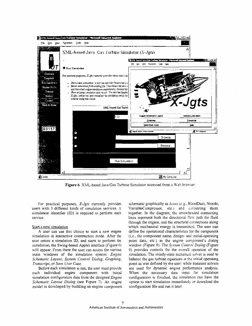
Figure 6 . XML-based Java Gas Turbine Simulator accessed from a Web bro\vs::
For practical purposes, X-Jgts currently provides users with 3 different kinds of simulation services. A simulation identifier (ID) is required to perfom each service.
Start a new simulation A user can use this choice to start a new engine
simulation in interactive construction mode. After the user enters a simulation ID, and starts to perform the simulation, the Swing-based Applet interface (Figure 6) will appear. From there the user can access the various main windows of the simulation system: Engine Schematic Layout, System Control Dialog, Graphing, Transcript, or Save User Case.
Before each simulation is run, the user must provide each individual engine component with initial simulation configuration data from the designed Engine Schematic Layout Dialog (see Figure 7). An engine model is developed by building an engine component
schematic graphically as Icons (e.g.. BktdDuct, Nozzle, VariableCompressor. etc.) and connecting them together. In the diagram, the arrowhesded connecting lines represent both the directional t'lon- path for fluid through the engine, and the structural connections along which mechanical energy is transmitted. The user can define the operational characteristics for the component (i.e., the component name, design- and initial-operating point data, etc.) in the engine component's dialog window (Figure 8). The $.stern Contrai Dialog (Figure 9) provides controls for the overall operation of the simulation. The steady-state numerical solver is used to balance the gas turbine equations at the initial operating point as was defined by the user: while transient solvers are used for dynamic engine perforniance analysis. When the necessary data input for simulation configuration is finished, the simulation can have the option to start simulation immediately or download the configuration file and run it later.
7 American Institute of Aeronautics and Astronautics
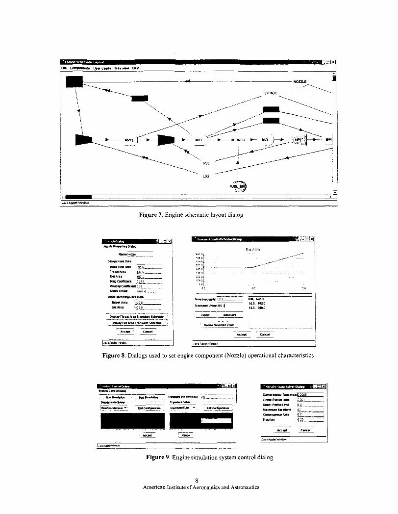
Figure 7. Engine schematic layout dialog
Figure 8. Dialogs used to set engine component (Nozzle) operational characteristics
Figure 9. Engine simulation system control dialog
8 American Institute of Aeronautics and Astronautics
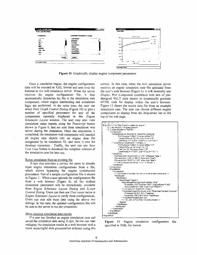
Figure 10. Graphically display engine component parameters
Once a simulation begins, the engine configuration data will be encoded in XML format and sent over the Internet to the web simulation server. When the server receives the engine configuration file, it then automatically dispatches the file to the simulation web component. where engine databinding and simulation logic are performed. At the same time, the user can select from Graph Control Dialog (Figure 10) to plot a number of specified parameters for any of the components currently displayed in the Engine Schematic Layout window. The user may also view simulation status reports, using the Transcript button shown in Figure 6, that are sent from simulation web server during the simulation. Once the simulation is completed, the simulation web component will marshal all engine data objects into an engine data file designated by its simulation ID, and store it into the database repository. Finally, the user can use Save User Case button to download the complete solution of the simulation case for later use.
Rerun simulation from an existing file X-Jgts also provides a service for users to directly
input engine simulation configurations from a file, which allows bypassing the engine construction procedures. Part of a sample configuration file is shown in Figure 11. When a user uploads the configuration file from a web browser (Figure 6), all the defined simulation parameters will be immediately available from Engine Schematic Layout Dialog and System Control Dialog. Users can then use User cases menu in Engine Schematic Layout to verify these configurations. Users can also edit these data using the above two dialogs. In this case, the updated configuration file will be sent to the server to run the simulation.
Show existing simulation data results If a user has finished an engine simulation case and
saved the simulation data using X-Jgts, heishe can later redisplay the simulation results in a web browser with a more meaningful data presentation scheme using this
service. In this case, when the web simulation server receives an engine simulation case file uploaded from the user's web browser (Figure 6), it will internally use Displaj. Web Component (combined with sets of pre- designed XSLT style sheets) to dynamically generate HTML code for display within the user's browser. Figure 12 shows the nozzle data file from an example simulation case. The user can choose different engine components to display from the drop-down list at the top of the web page.
<S:eaayStateSolver SioverNane. NewtoniiarisonSolve< ErorToierance- '5.OE-i ~Cswer~e*ceRate="0.7" literal1onToFa1lure="50 2eV':rsa: e-3 ze='O 25 LowerPacfalLlr,:='O 001C' 1;me+-a L ~ I F " O 01"')
ErrorToierance='5 OEd ' C~iv_e.gecceRale="O 7" In:erat,onToFali~re='50' 2e:al r e . : 2' FinaIT.,re='Z 0 Pend?a:oaSlze=': 25 LowerPan8aiL.mli='0 001C LisxrFar afL,mlt="O.O1" :>
<Connector :mm= Envimnmeni' :o= LPC' rieeaback="false',> <Connector frorr='LPC' :o='MVl3' sFeeoack="alse':> <Connector f,om="MV13" to= 'HPC' sFeemack="false'l> <I-. 3her connectors are defrreo 10 a s r a' vannar -->
<TpansfeniSoiver S:overName= I-~ovecE. e'
<Connec:on>
<,Connec!on> I- Conf.guration, +qneMoaeP
<Comwnents> <'-only Nozzle is illustrateo "ere the s3re wnh all other cornpnenrs -> <NonSource,
CNonRatator, CNozzie Name=~Nozzle">
<NozzleDesignPointDala Masr i owRa!e="195.0" TiroatArea-"430 0 Ex:Area='492.0" OragCoefheni="O 952 VelocltyCoeffc ew'0.98' G~ossThrus1-''9400 O?>
<'-lhe same with Noznelni!F-.~fDafa-~ <ThroatAreaTransienlontml,en qame=7hmat Area Transient Contmller"
<T,meArray> 0 0 10 0 13 C < TmeArray, 'VaiueAnay, 430 0 430 0 EiC 0 <,'ValueArray>
<I- :he same Nifh ix ; tArea~a~~ientContmi lers -> 'ThroatAreaTransienConuo eo>
<,Nozzle> <,NonRatalw>
<,NonSource> <.Comwnents
c EngineMwei> EPgineBase,
EngineRooP
Figure 11. Engine simulation configuration file specified in XML file format
9 American Institute of Aeronautics and Astronautics
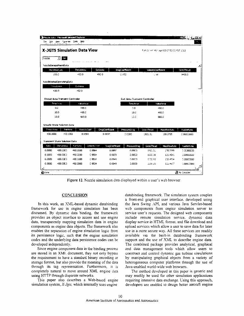
X-JGTS Simulation Data View
1-m . . . ~ _ _
1’3s 0 430 0 492 0 J ?52
N o z z l e l r n t k l l O p e r a t d t a
-mw#m 430 0 492 0
Throat Area Transtent Controller Exit Area Transient Controller
0.0 430.0
10.0 430.0
13.0 660.0
0.0
10.0
13 0
492 0
492.0
880.0
430 0000 ‘52 X O 0.9564 0 8897 0 0000 1921 3: 100 3765 0 00000000
Trdnsient S ta te Sdutm Data BmwB OoooO 430CoC; 4 9 2 W 09564 0 E097 0 0000 192: 31 io0 3765 C OOJOMOC
oim 43oca: 4920003 09554 0 E872 0 ooco 1922 3 io: 404: c wocmnc o:om 43ocit; w o o 0 0 cs37 0 iB43 0 ooco 2125 23 ;m 4554 5 oo0cmoc 03oOo 430cOCj 492oooO 09534 0 E843 0 0000 22% 23 :03 4b77 c MOOOOOC
I
4 Done ;i3 MY ComDuter
Figure 12. Nozzle simulation data displayed within a user’s web browser
COXCLUSION
In this work, an XML-based dynamic databinding framework for use in engine simulation has been discussed. By dynamic data binding, the framework provides an object interface to access and use engine data, transparently mapping simulation data in engine components as engine data objects. The framework also enables the separation of engine simulation logic from its persistence logic. such that the engine simulation codes and the underlying data persistence codes can be developed independently.
Since engine component data in the binding process are stored in an XML document, they not only bypass the requirement to have a standard binary encoding or storage format, but also provide the meaning of the data through its tag representation. Furthermore, it is completely natural to move around XML engine data using HTTP through disparate networks.
This paper also describes a Web-based engine simulation system, X-Jgfs, which internally uses engine
databinding framework. The simulation system couples a front-end graphical user interface. developed using the Java Swing API, and various Java Servlet-based web components from engine simulation server to service user’s requests. The designed web components include remote simulation service, dynamic data display service in HTML format. and file download and upload services which allow a user to save data for later use in a more secure way. All these services are readily available via the built-in databinding framework support and the use of XML to describe engine data. The combined package provides analytical, graphical and data management tools which allow users to construct and control dynamic gas turbine simulations by manipulating graphical objects from a variety of heterogeneous computer platforms through the use of Java-enabled world-wide web browsers.
The method developed in this paper is generic and may readily be used for other simulation applications requiring intensive data exchange. Using this approach, developers are enabled to design better aircraft engine
10 American Institute of Aeronautics and Astronautics
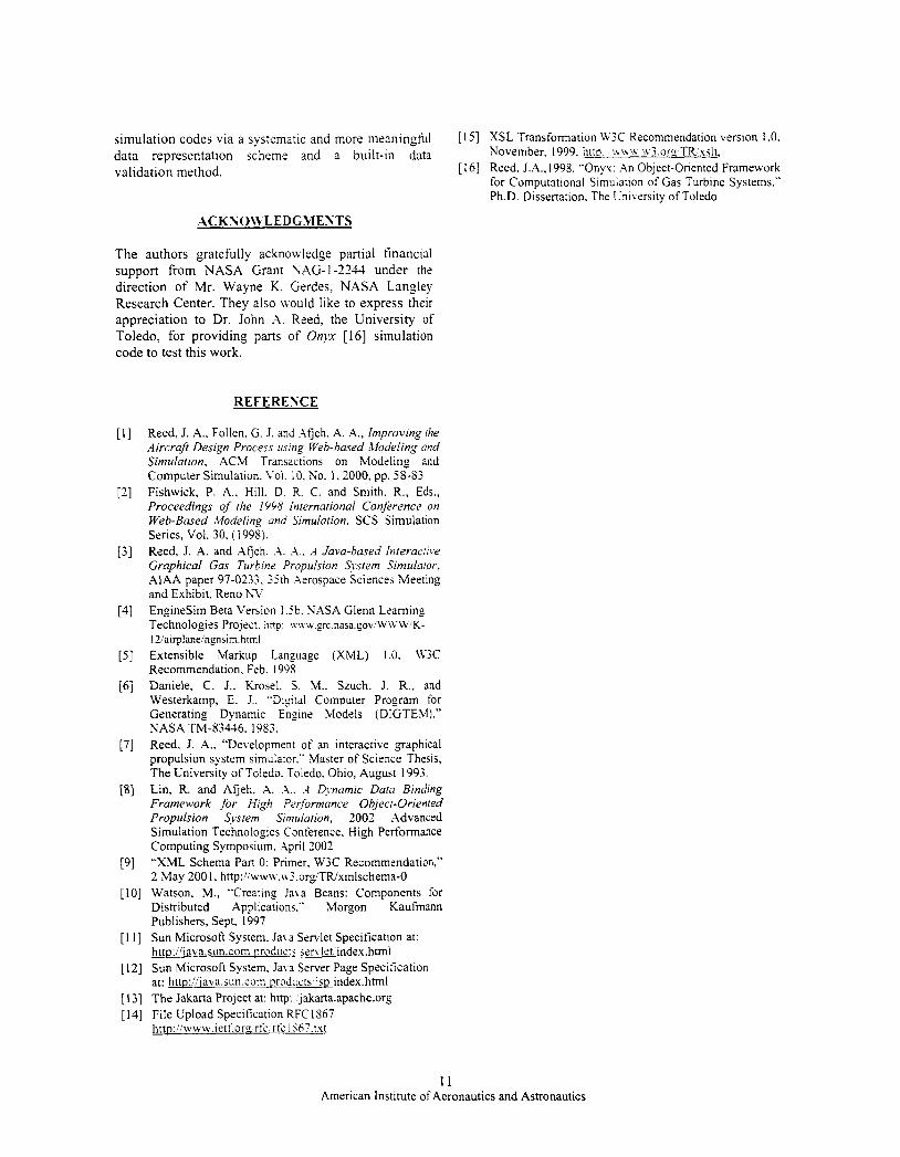
simulation codes via data representation validation method.
a systematic and more iiicaiiingh[ [ 151 XSL Transformation W3C Recommendation version 1.0.
[ 161 Reed, J.A.. 1998. "Onyx: A n Object-Oriented Framework for Computational Simulation of Gas Turbine Systems." Ph.D. Dissertation. The Cniversity of Toledo
scheme and a built-in data. November. 1999. hiiu: v.\\\\ .i.v3.orc TR.'xslt,
ACKSON'LEDGM ENTS
The authors gratefully acknoxvledge partial financial support from NASA Grant NAG-1-2234 under the direction of Mr. Wayne K. Gerdes, NASA Langley Research Center. They also n.ould like to express their appreciation to Dr. John A. Reed, the University of Toledo, for providing parts of 0nJ.K [I61 simulation code to test this work.
REFERESCE
Reed, J. A,, Follen. G. J. and Atjeh. A. A,, Improving the Aircraft Design Process using Web-based Modeling and Simulation, ACM Transactions on Modeling and Computer Simulation. Vol. 10. KO. 1.2000, pp. 58-S3 Fishwick, P. A,. Hill. D. R. C. and Smith. R., Eds., Proceedings of the I558 International Conference on Web-Based Modeling and Simulation. SCS Simulation Series, Vol. 30. ( 1998). Reed, J. A. and Xfjeh. A. A,. d Java-based Interactive Graphical Gas Turbine Propulsion S w e m Sirnzilator, AIAA paper 97-0233. 35th .\erospace Sciences Meeting and Exhibit. Reno h T EngineSim Beta Version l . ib. NASA Glenn Learning Technologies Project. hnp: n\% w . _ e r c . n a s a . g o v ' w \ ~ ~ V ~ K - I Z/airplaneinpsim.hrml Extensible Markup Language (XML) 1 .O. lV3C Recommendation. Feb. 1993 Daniele, C . J., Krosel. S. M.. Szuch. J. R., and Westerkamp, E. J.. "Dig:tal Computer Program for Generating Dynamic Engine Models (DIGTEM)."
Reed, J. A., "Development of an interactive graphical propulsion system simulator." Master of Science Thesis, The University of Toledo. Toledo. Ohio, August 1993. Lin, R. and Afieh, A. .i.. .-1 Diwamic Data Binding Framework for High Pz$ormance Object-Oriented Propulsion Svstem Similarion, 2002 Advanced Simulation Technologies Conference. High Performance Computing Symposium. April 2002 "XML Schema Part 0: Primer. W3C Recommendation," 2 May 2001. http:!iww\v.\\3,org/TIUxmlschema-0
NASA TM-83446. 1983.
[ I O ] Watson, M., "Creating Java Beans: Components for Distributed Applications." Morgon Kaufmann Publishers, Sept. 1997
[ 1 I ] Sun Microsoft System. Jat a Servlet Specification at: httu://iava.stm.com nrodiic:s servlet index.html
[ 121 Sun Microsoft System. Java Server Page Specification at: httu::'iava.sun.com m x i x i s , isp index.html
[ I 31 The Jakarta Project at: http: jakarta.apache.org [I41 File Upload Specification RFC1867
http:!./www.ietf.orc rfc ric I867.txt
11 American Institute of Aeronautics and Astronautics
Reed. J . ; I . . Fdiet7, G. .j. unci AJjeh. ‘-1. ,-I
Improving the Aircraft Design Process Using Web-based Modeling and Simulation
John A. Reed?, Gregory J. Follenz, and Abdollah A. Afjeht
tThe University of Toledo
2801 West Bancroft Street
Toledo, Ohio 43606
:NASA John H. Glenn Research Center
2 1000 Brookpark Road
Cleveland, Ohio 44135
Keywords: Web-based simulation, aircraft design, distributed simulation, JavaTM, object-oriented
~~ ~ ~ ~~
Supported by the High Performance Computing and Communication Project (HPCCP) at the NASA Glenn Research Center.
Page 1 of35
Abstract
Designing and developing new aircraft systems is time-consuming and expensive.
Computational simulation is a promising means for reducing design cycle times, but requires a
flexible software environment capable of integrating advanced multidisciplinary and muitifidelity
analysis methods, dynamically managing data across heterogeneous computing platforms, and
distributing computationally complex tasks. Web-based simulation, with its emphasis on
collaborative composition of simulation models, distributed heterogeneous execution, and
dynamic multimedia documentation, has the potential to meet these requirements. This paper
outlines the current aircraft design process, highlighting its problems and complexities, and
presents our vision of an aircraft design process using Web-based modeling and simulation.
Page 2 of 35
1 Introduction
Intensive competition in the commercial aviation industry is placing increasing pressure on
aircraft manufacturers to reduce the time, cost and risk of product development. To compete
effectively in today’s global marketplace, innovative approaches to reducing aircraft design-cycle
times are needed. Computational simulation, such as computational fluid dynamics (CFD) and
finite element analysis (FEA), has the potential to compress design-cycle times due to the
flexibility it provides for rapid and relatively inexpensive evaluation of alternative designs and
because it can be used to integrate multidisciplinary analysis earlier in the design process [ 171.
Unfortunately, bottlenecks caused by data handling, heterogeneous computing environments and
geographically separated design teams, continue to restrict the use of these tools. In order to fully
realize the potential of computational simulation, improved integration in the overall design
process must be made. The opportunity now exists to take advantage of recent developments in
information technology to streamline the design process so that information can flow seamlessly
between applications, across heterogeneous operating systems, computing architectures
programming languages, and data and process representations.
The World Wide Web has emerged as a powerful mechanism for distributing information on a
very large scale. In its current form, it provides a simple and effective means for users to search,
browse, and retrieve information, as well as to publish their own information. The Web continues
to evolve from its limited role as a provider of static document-based information to that of a
platform for supporting complex services. Much of this transformation is due to the introduction
of object technologies, such as Java and CORBA (Common Object Request Broker Architecture)
[36] within the Web. The integration of object technology represents a fundamental (some would
say, revolutionary) advancement in web-technology. The web is no longer simply a document
access system supported by the somewhat limited protocols. Rather, it is a distributed object
system with which one can build general, multi-tiered enterprise intranet and internet
applications.
Page 3 of 35
The integration of the Web and object technology enables a fbndamentally new approach to
simulation: Meb-based simulation. A Web populated with digital objects - models of physical
counterparts - will lead to model development by composition using collaborative Web-based
environments [9 ] . Model execution will occur across networks using Web-based technologies
(e.g., Java) and distributed simulation techniques (e.g., COMA). Finally, simulation execution,
models, and other related data will be documented using forms of hypermedia (hypertext, video,
virtual models, etc.).
Web-based simulation has the potential to provide the necessary tools to improve the aircraft
design process through integration and support for collaborative modeling and distributed model
execution. In the remainder of this paper, we examine how this might be achieved. In Section 2,
we provide a brief overview of the aircraft design process, drawing attention to the complexities
of the process and its inherent problems. Section 3 provides a review of the area of Web-based
simulation, and singles out several principles of Web-based simulation that we believe are
important in the aircraft design process. In Section 4, we present an example scenario illustrating
how Web-based modeling and simulation might be used in that process, and discuss aircraft
model development and distribution using the Onyx simulation framework. Onyx's object-
oriented component model, visual environment for model assembly, and support for both Web-
based and distributed object execution are explained in context of the integration of a jet engine
within the aircraft. Lastly, in Section 5 , the relationships to the Web-based simulation principles
outlined in Section 3 are identified and discussed, as are general implications of Web-based
simulation on the design process.
2 The Aircraft Design Process
The aircraft design process can be divided into three phases: conceptual design, preliminary
design, and detailed design. The conceptual design phase identifies the various conditions of the
mission, and synthesizes a set of initial aircraft configurations capable of performing the mission.
For commercial aircraft, the mission is defined by airline company demands, which typically
Page 4 of 35
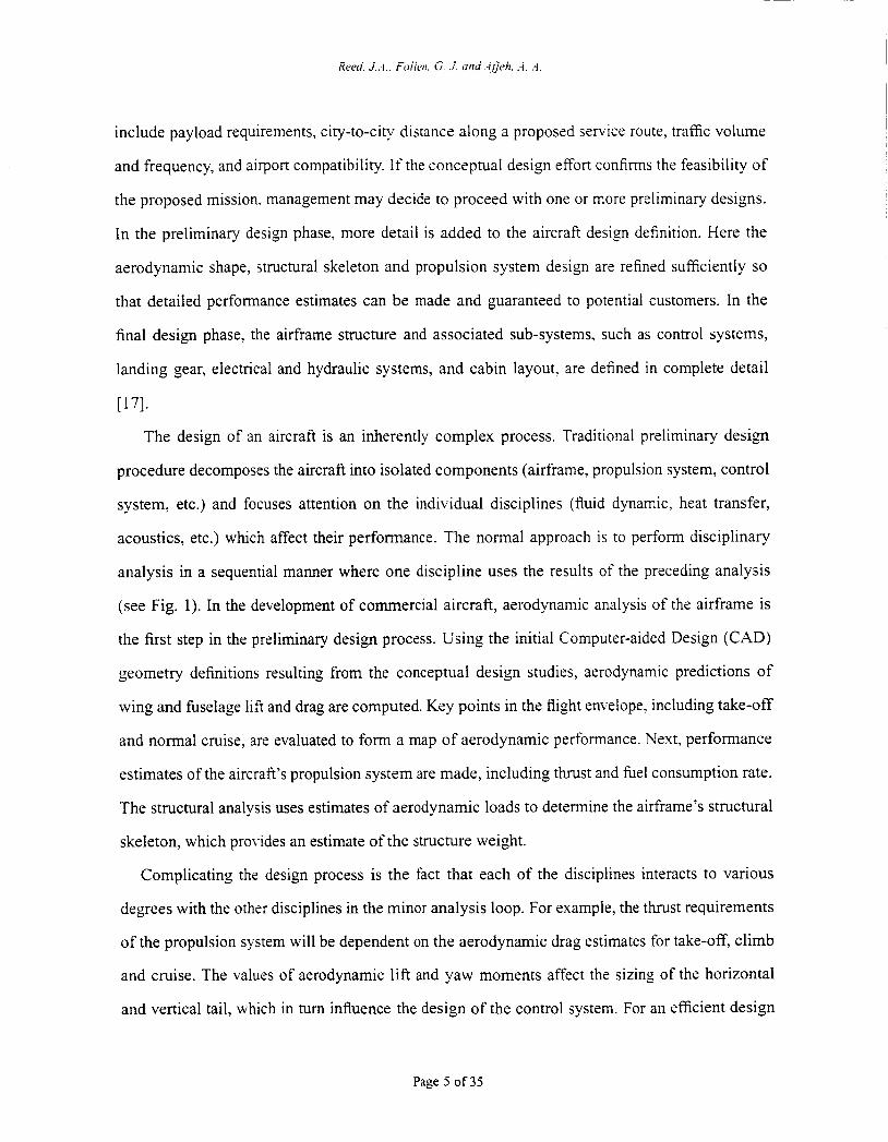
include payload requirements, city-to-city distance along a proposed service route, traffic volume
and frequency, and airport compatibility. If the conceptual design effort confirms the feasibility of
the proposed mission. management may decide to proceed with one or more preliminary designs.
In the preliminary design phase. more detail is added to the aircraft design definition. Here the
aerodynamic shape, structural skeleton and propulsion system design are refined sufficiently so
that detailed performance estimates can be made and guaranteed to potential customers. In the
final design phase, the airframe structure and associated sub-systems, such as control systems,
landing gear, electrical and hydraulic systems, and cabin layout, are defined in complete detail
~ 7 1 .
The design of an aircraft is an inherently complex process. Traditional preliminary design
procedure decomposes the aircraft into isolated components (airframe, propulsion system, control
system, etc.) and focuses attention on the individual disciplines (fluid dynamic, heat transfer,
acoustics, etc.) which affect their performance. The normal approach is to perform disciplinary
analysis in a sequential manner where one discipline uses the results of the preceding analysis
(see Fig. 1). In the development of commercial aircraft, aerodynamic analysis of the airframe is
the first step in the preliminary design process. Using the initial Computer-aided Design (CAD)
geometry definitions resulting from the conceptual design studies, aerodynamic predictions of
wing and fbselage lift and drag are computed. Key points in the flight envelope. including take-off
and normal cruise, are evaluated to form a map of aerodynamic performance. Next, performance
estimates of the aircraft’s propulsion system are made, including thrust and fuel consumption rate.
The structural analysis uses estimates of aerodynamic loads to determine the airframe’s structural
skeleton, which provides an estimate of the structure weight.
Complicating the design process is the fact that each of the disciplines interacts to various
degrees with the other disciplines in the minor analysis loop. For example, the thrust requirements
of the propulsion system will be dependent on the aerodynamic drag estimates for take-off, climb
and cruise. The values of aerodynamic lift and yaw moments affect the sizing of the horizontal
and vertical tail, which in turn influence the design of the control system. For an efficient design
Page 5 of 35
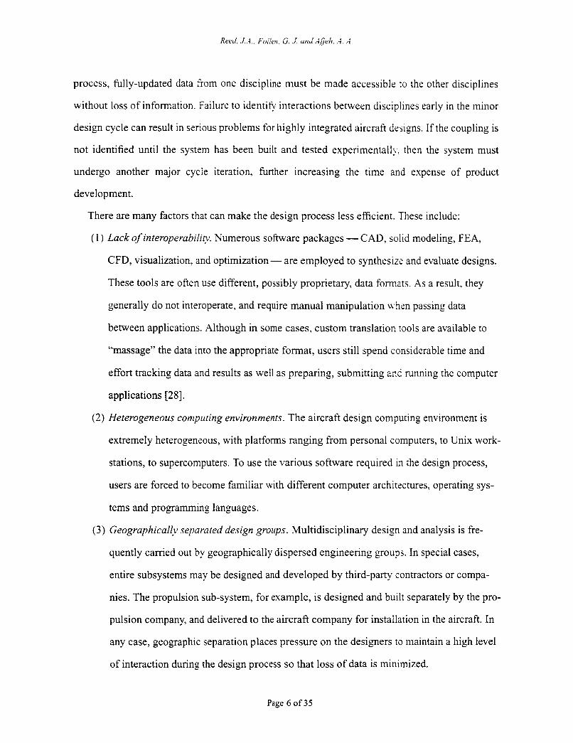
process, fully-updated data from one discipline must be made accessible to the other disciplines
without loss of information. Failure to identify interactions between disciplines early in the minor
design cycle can result in serious problems for highly integrated aircraft designs. If the coupling is
not identified until the system has been built and tested experimentally. then the system must
undergo another major cycle iteration, further increasing the time and expense of product
development.
There are many factors that can make the design process less efficient. These include:
(1) Lack of interoperability. Numerous software packages - CAD, solid modeling, FEA,
CFD, visualization, and optimization - are employed to synthesizs and evaluate designs.
These tools are often use different, possibly proprietary, data formats. As a result, they
generally do not interoperate, and require manual manipulation Lvha passing data
between applications. Although in some cases, custom translation tools are available to
“massage” the data into the appropriate format, users still spend considerable time and
effort tracking data and results as well as preparing, submitting and running the computer
applications [28].
( 2 ) Heterogeneous conzpriting environments. The aircraft design computing environment is
extremely heterogeneous, with platforms ranging from personal computers, to Unix work-
stations, to supercomputers. To use the various software required in the design process,
users are forced to become familiar with different computer architectures, operating sys-
tems and programming languages.
(3) Geographically separated design groirps. Multidisciplinary design and analysis is fie-
quently carried out by geographically dispersed engineering groups. In special cases,
entire subsystems may be designed and developed by third-party contractors or compa-
nies. The propulsion sub-system, for example, is designed and built separately by the pro-
pulsion company, and delivered to the aircraft company for installation in the aircraft. In
any case, geographic separation places pressure on the designers to maintain a high level
of interaction during the design process so that loss of data is minimized.
Page 6 of 35
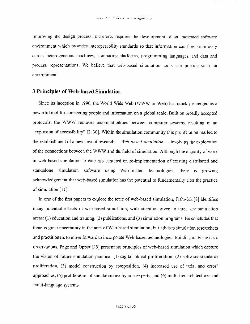
Improving the design process. therefore, requires the development of an integrated software
environment which provides interoperability standards so that information can flow seamlessly
across heterogeneous machines, computing platforms, programming languages. and data and
process representations. We believe that web-based simulation tools can provide such an
environment.
3 Principles of Web-based Simulation
Since its inception in 1990, the World Wide Web (WWW or Web) has quickly emerged as a
powerful tool for connecting people and information on a global scale. Built on broadly accepted
protocols, the WWW removes incompatibilities between computer systems. resulting in an
“explosion of accessibility” [2. 301. Within the simulation community this proliferation has led to
the establishment of a new area of research - Web-based simulation - involving the exploration
of the connections between the WWW and the field of simulation. Although the majority of work
in web-based simulation to date has centered on re-implementation of existing distributed and
standalone simulation software using Web-related technologies, there is growing
acknowledgement that web-based simulation has the potential to fundamentally alter the practice
of simulation [ 1 11.
In one of the first papers to explore the topic of web-based simulation, Fishwick [8] identifies
many potential effects of web-based simulation, with attention given to three key simulation
areas: (1) education and training, (2) publications, and (3) simulation programs. He concludes that
there is great uncertainty in the area of Web-based simulation, but advises simulation researchers
and practitioners to move forward to incorporate Web-based technologies. Building on Fishwick’s
observations, Page and Opper [25] present six principles of web-based simulation which capture
the vision of future simulation practice: (1) digital object proliferation, (2) software standards
proliferation, (3) model construction by composition, (4) increased use of -’mal and error”
approaches, (5) proliferation of simulation use by non-experts, and (6) multi-tier architectures and
multi-language systems.
Page 7 of 35
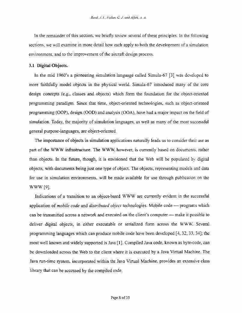
In the remainder of this section, we briefly review several of these principles. In the following
sections, we will examine in more detail how each apply to both the development of a simulation
environment, and to the improvement of the aircraft design process.
3.1 Digital Objects.
In the mid 1960’s a pioneering simulation language called Simula-67 [3] was developed to
more faithfully model objects in the physical world. Simula-67 introduced many of the core
design concepts (e.g., classes and objects) which form the foundation for the object-oriented
programming paradigm. Since that time, object-oriented technologies, such as object-oriented
programming (OOP), design (OOD) and analysis (OOA), have had a major impact on the field of
simulation. Today, the majority of simulation languages, as well as many of the most successful
general purpose-languages, are object-oriented.
The importance of objects in simulation applications naturally leads us to consider their use as
part of the WWW infrastructure. The WWW, however, is currently based on documents. rather
than objects. In the future, though, it is envisioned that the Web will be populated by digital
objects, with documents being just one type of object. The objects, representing models and data
for use in simulation environments, will be made available for use through publication on the
WWW [9].
Indications of a transition to an object-based WWW are currently evident in the successful
application of mobile code and distributed object technologies. Mobile code - programs which
can be transmitted across a network and executed on the client’s computer - make it possible to
deliver digital objects, in either executable or serialized form across the WWW. Several
programming languages which can produce mobile code have been developed [3,32,33.34]; the
most well known and widely supported is Java [ 11. Compiled Java code, known as byte-code, can
be downloaded across the Web to the client where it is executed by a Java Virtual Machine. The
Java run-time system, incorporated within the Java Virtual Machine, provides an extensive class
library that can be accessed by the compiled code.
Page 8 of 35
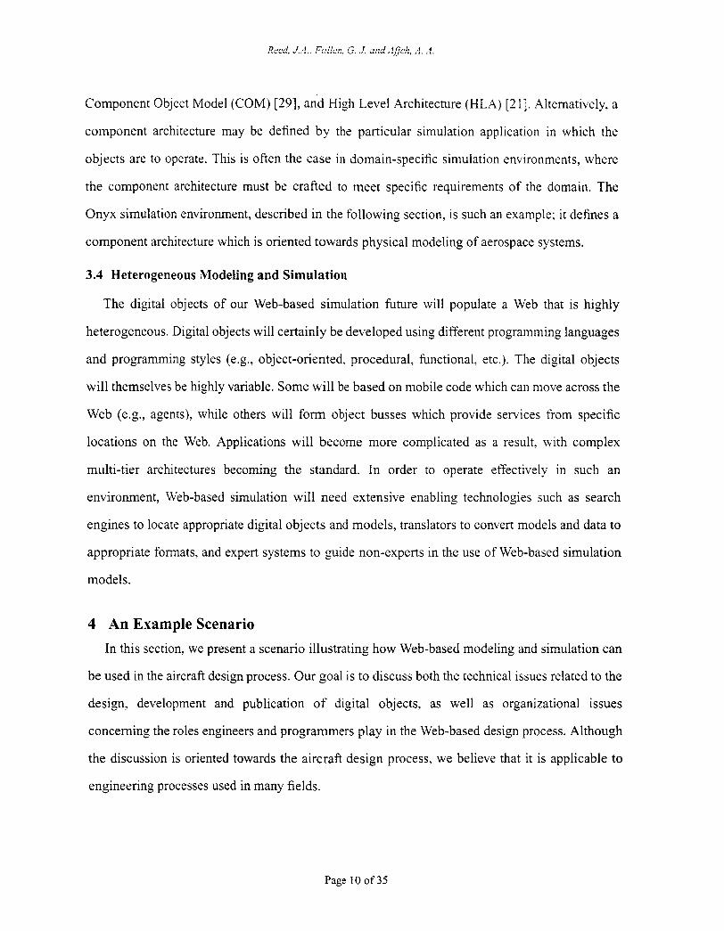
Component Object Model (COM) [29], and High Level Architecture (HLA) [2 11. Alternatively, a
component architecture may be defined by the particular simulation application in which the
objects are to operate. This is often the case in domain-specific simulation environments, where
the component architecture must be crafted to meet specific requirements of the domain. The
Onyx simulation environment, described in the following section, is such an example; it defines a
component architecture which is oriented towards physical modeling of aerospace systems.
3.4 Heterogeneous Modeling and Simulation
The digital objects of our Web-based simulation future will populate a Web that is highly
heterogeneous. Digital objects will certainly be developed using different programming languages
and programming styles (e.g., object-oriented, procedural, functional, etc.). The digital objects
will themselves be highly variable. Some will be based on mobile code which can move across the
Web (e.g., agents), while others will form object busses which provide services from specific
locations on the Web. Applications will become more complicated as a result, with complex
multi-tier architectures becoming the standard. In order to operate effectively in such an
environment, Web-based simulation will need extensive enabling technologies such as search
engines to locate appropriate digital objects and models, translators to convert models and data to
appropriate formats, and expert systems to guide non-experts in the use of Web-based simulation
models.
4 An Example Scenario In this section, we present a scenario illustrating how Web-based modeling and simulation can
be used in the aircraft design process. Our goal is to discuss both the technical issues related to the
design, development and publication of digital objects, as well as organizational issues
concerning the roles engineers and programmers play in the Web-based design process. Although
the discussion is oriented towards the aircraft design process, we believe that it is applicable to
engineering processes used in many fields.
Page 10 of35
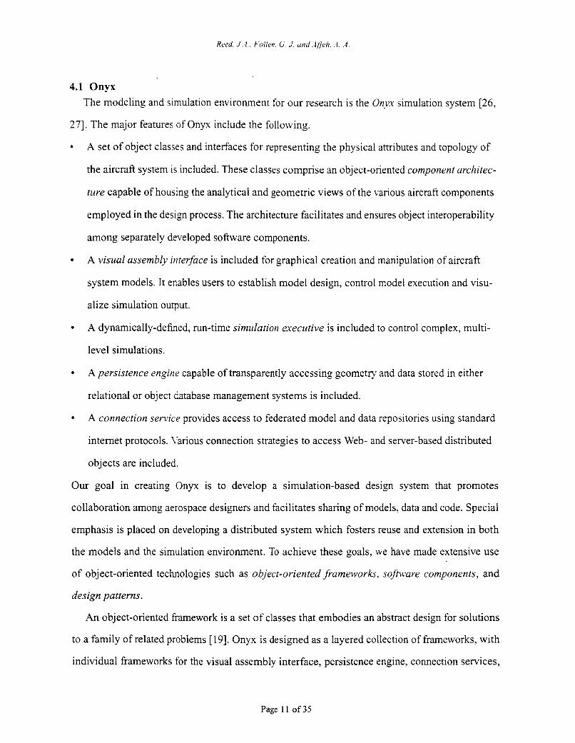
4.1 Onyx The modeling and simulation environment for our research is the Onyx simulation system [26.
271. The major features of Onyx include the following.
A set of object classes and interfaces for representing the physical attributes and topology of
the aircraft system is included. These classes comprise an object-oriented component architec-
ture capable of housing the analytical and geometric views of the various aircraft components
employed in the design process. The architecture facilitates and ensures object interoperability
among separately developed software components.
A visual assembly irtrerface is included for graphical creation and manipulation of aircraft
system models. It enables users to establish model design, control model execution and visu-
alize simulation output.
A dynamically-defined, run-time simzdation executive is included to control complex, multi-
level simulations.
A persistence engine capable of transparently accessing geometry and data stored in either
relational or object database management systems is included.
A connection service provides access to federated model and data repositories using standard
internet protocols. r-arious connection strategies to access Web- and server-based distributed
objects are included.
Our goal in creating Onyx is to develop a simulation-based design system that promotes
collaboration among aerospace designers and facilitates sharing of models, data and code. Special
emphasis is placed on developing a distributed system which fosters reuse and extension in both
the models and the simulation environment. To achieve these goals, we have made extensive use
of object-oriented technologies such as object-oriented frameworks, sofnvare components, and
design patterns.
An object-oriented framework is a set of classes that embodies an abstract design for solutions
to a family of related problems [ 191. Onyx is designed as a layered collection of frameworks, with
individual frameworks for the visual assembly interface, persistence engine, connection services,
Page 11 of 35
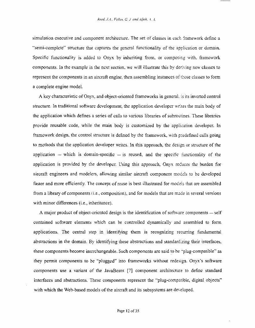
simulation executive and component architecture. The set of classes in each framework define a
“semi-complete” structure that captures the general functionality of the application or domain.
Specific functionality is added to Onyx by inheriting from, or composing with, framework
components. In the example in the next section, we will illustrate this by denying new classes to
represent the components in an aircraft engine, then assembling instances of those classes to form
a complete engine model.
A key characteristic of Onyx, and object-oriented frameworks in general. is its inverted control
structure. In traditional software development, the application developer writes the main body of
the application which defines a series of calls to various libraries of subroutines. These libraries
provide reusable code, while the main body is customized by the application developer. In
framework design, the control structure is defined by the framework, with predefined calls going
to methods that the application developer writes. In this approach, the design or structure of the
application - which is domain-specific - is reused, and the specific iunctionality of the
application is provided by the developer. Using this approach, Onyx reduces the burden for
aircraft engineers and modelers, allowing similar aircraft component mod& to be developed
faster and more efficiently. The concept of reuse is best illustrated for modtij that are assembled
from a library of components (i.e., composition), and for models that are made in several versions
with minor differences (i.e., inheritance).
A major product of object-oriented design is the identification of sofnvare components - self
contained software elements which can be controlled dynamically and assembled to form
applications. The central step in identifying them is recognizing rscumng fundamental
abstractions in the domain. By identifLing these abstractions and standardizing their interfaces,
these components become interchangeable. Such components are said to be ”plug-compatible” as
they permit components to be “plugged” into frameworks without redesign. Onyx’s software
components use a variant of the JavaBeans [7] component architecture to define standard
interfaces and abstractions. These components represent the “plug-compatible, digital objects”
with which the Web-based models of the aircraft and its subsystems are de\-eloped.
Page 12 of 35
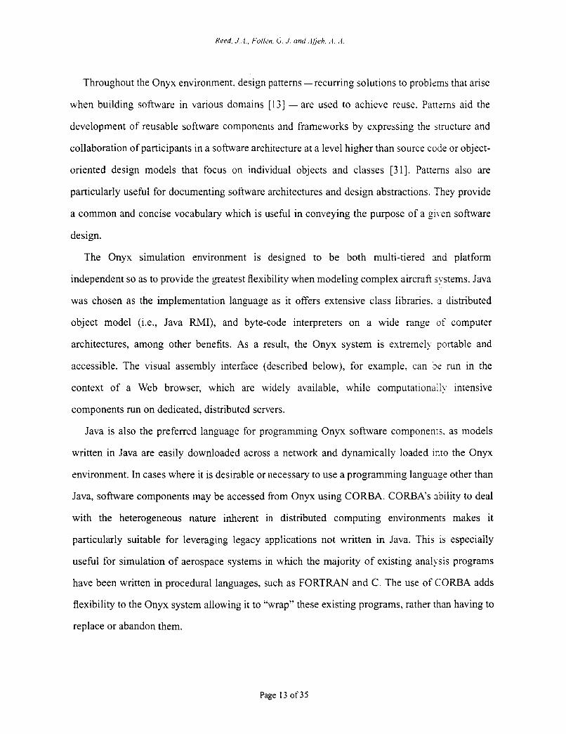
Throughout the Onyx environment, design patterns -recurring solutions to problems that arise
when building software in various domains [ 131 - are used to achieve reuse. Patterns aid the
development of reusable software components and frameworks by expressing the structure and
collaboration of participants in a software architecture at a level higher than source code or object-
oriented design models that focus on individual objects and classes [31]. Patterns also are
particularly useful for documenting software architectures and design abstractions. They provide
a common and concise vocabulary which is useful in conveying the purpose of a @\-en software
design.
The Onyx simulation environment is designed to be both multi-tiered and platform
independent so as to provide the greatest flexibility when modeling complex aircraft systems. Java
was chosen as the implementation language as it offers extensive class libraries. a distributed
object model (Le., Java RMI), and byte-code interpreters on a wide range of computer
architectures, among other benefits. As a result, the Onyx system is extremely portable and
accessible. The visual assembly interface (described below), for example, can be run in the
context of a Web browser, which are widely available, while computationally intensive
components run on dedicated, distributed servers.
Java is also the preferred language for programming Onyx software componenrs. as models
written in Java are easily downloaded across a network and dynamically loaded into the Onyx
environment. In cases where it is desirable or necessary to use a programming languagz other than
Java, software components may be accessed from Onyx using COMA. CORI3A’s ability to deal
with the heterogeneous nature inherent in distributed computing environments makes it
particularly suitable for leveraging legacy applications not written in Java. This is especially
useful for simulation of aerospace systems in which the majority of existing analysis programs
have been written in procedural languages, such as FORTRAN and C. The use of C O M A adds
flexibility to the Onyx system allowing it to “wrap” these existing programs, rather than having to
replace or abandon them.
Page 13 of35
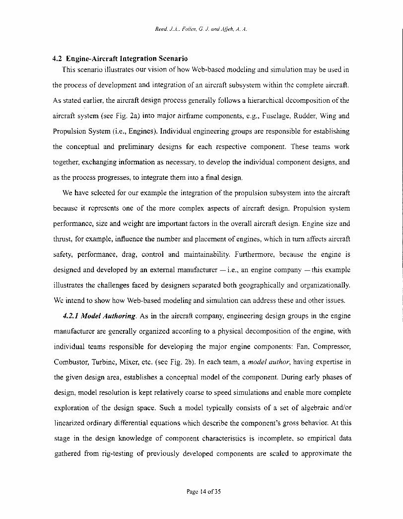
Reed. J . . I . , Foiien, G J: und Ajjeh. A. .-i.
4.2 Engine-Aircraft Integration Scenario This scenario illustrates our vision of how Web-based modeling and simulation may be used in
the process of development and integration of an aircraft subsystem within the complete aircraft.
As stated earlier, the aircraft design process generally follows a hierarchical decomposition of the
aircraft system (see Fig. 2a) into major airframe components, e.g., Fuselage, Rudder, Wing and
Propulsion System (i.e., Engines). Individual engineering groups are responsible for establishing
the conceptual and preliminary designs for each respective component. These teams work
together, exchanging information as necessary, to develop the individual component designs, and
as the process progresses, to integrate them into a final design.
We have selected for our example the integration of the propulsion subsystem into the aircraft
because it represents one of the more complex aspects of aircraft design. Propulsion system
performance, size and weight are important factors in the overall aircraft design. Engine size and
thrust, for examp!e, influence the number and placement of engines, which in turn affects aircraft
safety, performance, drag, control and maintainability. Furthermore, because the engine is
designed and developed by an external manufacturer - Le., an engine company -this example
illustrates the challenges faced by designers separated both geographically and organizationally.
We intend to show how Web-based modeling and simulation can address these and other issues.
4.2.1 Model Authoring. As in the aircraft company, engineering design groups in the engine
manufacturer are generally organized according to a physical decomposition of the engine, with
individual teams responsible for developing the major engine components: Fan. Compressor,
Combustor, Turbine, Mixer, etc. (see Fig. 2b). In each team, a model author, having expertise in
the given design area, establishes a conceptual model of the component. During early phases of
design, model resolution is kept relatively coarse to speed simulations and enable more complete
exploration of the design space. Such a model typically consists of a set of algebraic andor
linearized ordinary differential equations which describe the component’s gross behavior. At this
stage in the design knowledge of component characteristics is incomplete, so empirical data
gathered from rig-testing of previously developed components are scaled to approximate the
Page 14 of 35
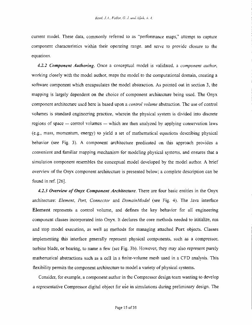
current model. These data, commonly referred to as “performance maps,” attempt to capture
component characteristics within their operating range, and serve to provide closure to the
equations.
4.2.2 Component Authoring. Once a conceptual model is validated, a component author,
working closely with the model author, maps the model to the computational domain, creating a
software component which encapsulates the model abstraction. As pointed out in section 3, the
mapping is largely dependent on the choice of component architecture being used. The Onyx
component architecture used here is based upon a control volume abstraction. The use of control
volumes is standard engineering practice, wherein the physical system is divided into discrete
regions of space - control volumes - which are then analyzed by applying conservation laws
(e.g., mass, momentum, energy) to yield a set of mathematical equations describing physical
behavior (see Fig. 3). A component archtecture predicated on this approach provides a
convenient and familiar mapping mechanism for modeling physical systems, and ensures that a
simulation component resembles the conceptual model developed by the model author. A brief
overview of the Onyx component architecture is presented below; a complete description can be
found in ref. [26].
4.2.3 Overview of Onyx Component Architecture. There are four basic entities in the Onyx
architecture: Element, Port, Connector and DomainModel (see Fig. 4). The Java interface
Element represents a control volume, and defines the key behavior for all engineering
component classes incorporated into Onyx. It declares the core methods needed to initialize, run
and stop model execution, as well as methods for managing attached Port objects. Classes
implementing this interface generally represent physical components, such as a compressor,
turbine blade, or bearing, to name a few (see Fig. 3b). However, they may also represent purely
mathematical abstractions such as a cell in a finite-volume mesh used in a CFD analysis. This
flexibility permits the component architecture to model a variety of physical systems.
Consider, for example, a component author in the Compressor design team wanting to develop
a representative Compressor digital object for uie in simulations during preliminary design. The
Page 15 of 35
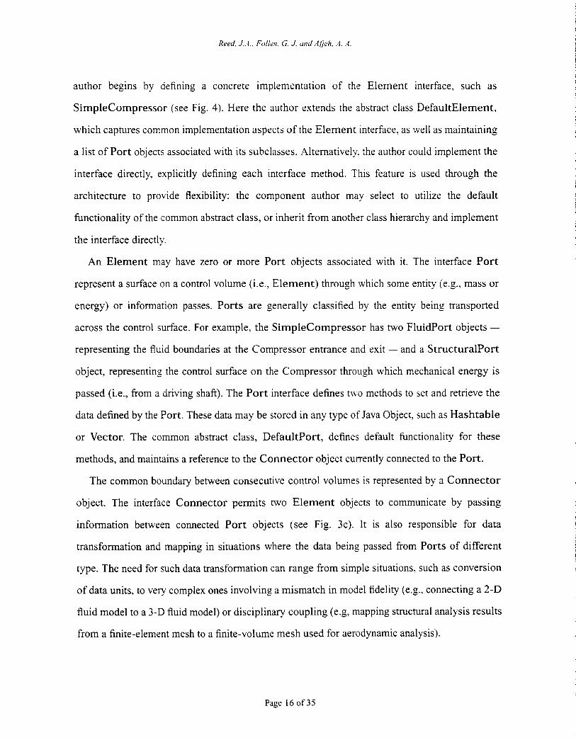
Reed. J A . . Folleri. G. J. and Ajjeh. .,I. .4.
author begins by defining a concrete implementation of the Element interface, such as
Simplecompressor (see Fig. 4). Here the author extends the abstract class DefaultElement.
which captures common implementation aspects of the Element interface, as well as maintaining
a list of Port objects associated with its subclasses. Alternatively. the author could implement the
interface directly, explicitly defining each interface method. This feature is used through the
architecture to provide flexibility: the component author may select to utilize the default
functionality of the common abstract class, or inherit from another class hierarchy and implement
the interface directly.
An Element may have zero or more Port objects associated with it. The interface Port
represent a surface on a control volume (Le., Element) through which some entity (e.g., mass or
energy) or information passes. Ports are generally classified by the entity being transported
across the control surface. For example, the SimpleCompressor has two FluidPort objects -
representing the fluid boundaries at the Compressor entrance and exit - and a StructuralPort
object, representing the control surface on the Compressor through which mechanical energy is
passed (Le., from a driving shaft). The Port interface defines t\vo methods to set and retrieve the
data defined by the Port. These data may be stored in any type of Java Object, such as Hashtable
or Vector. The common abstract class, Defaultport, defines default functionality for these
methods, and maintains a reference to the Connector object currently connected to the Port.
The common boundary between consecutive control volumes is represented by a Connector
object. The interface Connector permits two Element objects to communicate by passing
information between connected Port objects (see Fig. 3c). It is also responsible for data
transformation and mapping in situations where the data being passed from Ports of different
type. The need for such data transformation can range from simple situations. such as conversion
of data units, to very complex ones involving a mismatch in model fidelity (e.g., connecting a 2-D
fluid model to a 3-D fluid model) or disciplinary coupling (e.g, mapping structural analysis results
from a finite-element mesh to a finite-volume mesh used for aerodynamic analysis).
Page 16 of35
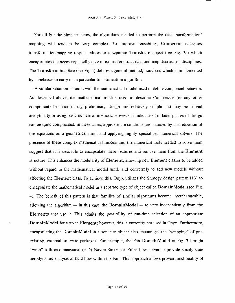
For all but the simplest cases, the algorithms needed to perform the data transformation/’
mapping will tend to be very complex. To improve reusability. Connector delegates
transformatiodmapping responsibilities to a separate Transform object (see Fig. 3c) which
encapsulates the necessary intelligence to expand’contract data and map data across disciplines.
The Transform interface (see Fig 4) defines a general method, transform, which is implemented
by subclasses to carry out a particular transformation algorithm.
A similar situation is found with the mathematical model used to define component behavior.
As described above, the mathematical models used to describe Compressor (or any other
component) behavior during preliminary design are relatively simple and may be solved
analytically or using basic numerical methods. However, models used in latter phases of design
can be quite complicated. In these cases, approximate solutions are obtained by discretization of
the equations on a geometrical mesh and applying highly specialized numerical solvers. The
presence of these complex mathematical models and the numerical tools needed to solve them
suggest that it is desirable to encapsulate these features and remove them from the Element
structure. This enhances the modularity of Element, allowing new Element classes to be added
without regard to the mathematical model used. and conversely to add new models without
affecting the Element class. To achieve this, Onyx utilizes the Strategy design pattern [13] to
encapsulate the mathematical model in a separate type of object called DomainModel (see Fig.
4). The benefit of this pattern is that families of similar algorithms become interchangeable.
allowing the algorithm - in this case the DomainModel - to yary independently from the
Elements that use it. This admits the possibility of run-time selection of an appropriate
DomainModel for a given Element; however, this is currently not used in Onyx. Furthermore,
encapsulating the DomainModel in a separate object also encourages the “wrapping” of pre-
existing, external sofnvare packages. For example, the Fan DomainModel in Fig. 3d might
“wrap” a three-dimensional (3-D) Navier-Stokes or Euler flow solver to provide steady-state
aerodynamic analysis of fluid flow within the Fan. This approach allows proven functionality of
Page 17 of 35
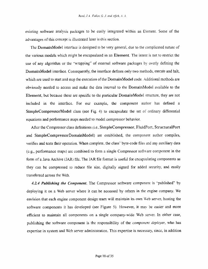
existing software analysis packages to be easily integrated within an Elsment. Some of the
advantages of this concept is illustrated later in this section.
The DomainModel interface is designed to be very general, due to the complicated nature of
the various models which might be encapsulated in an Element. The intent is not to restrict the
use of any algorithm or the ”wrapping” of external software packages by overly defining the
DomainModel interface. Consequently, the interface defines only two methods, execute and halt,
which are used to start and stop the execution of the DomainModel code. Additional methods are
obviously needed to access and make the data internal to the DomainModel available to the
Element, but because these are specific to the particular DomainModel structure, they are not
included in the interface. For our example, the component author has defined a
SimpleCompressorModel class (see Fig. 4) to encapsulate the set of ordinary differential
equations and performance maps needed to model compressor behavior.
After the Compressor class definitions (i.e., SimpleCompressor, Fluidport. StructuralPort
and SimpleCompressorDomainModel) are established, the componsnr author compiles,
verifies and tests their operation. When complete. the class’ byte-code files and any auxiliary data
(e.g., performance maps) are combined to form a single Compressor sofmare component in the
form of a Java Archive (JAR) file. The JAR file format is useful for encapsulating components as
they can be compressed to reduce file size, digitally signed for added security, and easily
transferred across the Web.
4.2.4 Publishing the Component. The Compressor software component is “published” by
deploying it on a Web sen-er where it can be accessed by others in the engine company. We
envision that each engine component design team will maintain its own U b server, hosting the
software components it has developed (see Figure 5) . However, it may be easier and more
efficient to maintain all components on a single company-wide Web sener. In either case,
publishing the software component is the responsibility of the component deployer, who has
expertise in system and Web server administration. This expertise is necessary, since, in addition
Page 18 of 35
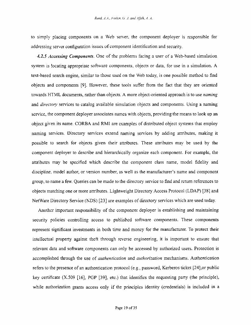
to simply placing components on a Web server, the component deployer is responsible for
addressing server configuration issues of component identification and security.
42.5 Accessing Components. One of the problems facing a user of a Web-based simulation
system is locating appropriate software components, objects or data, for use in a simulation. A
text-based search engine, similar to those used on the Web today, is one possible method to find
objects and components [9]. However, these tools suffer from the fact that they are oriented
towards HTML documents, rather than objects. A more object-oriented approach is to use naming
and directory services to catalog available simulation objects and components. Using a naming
service, the component deployer associates names with objects, providing the means to look up an
object given its name. CORBA and RMI are examples of distributed object systems that employ
naming services. Directory services extend naming services by adding attributes, making it
possible to search for objects given their attributes. These attributes may be used by the
component deployer to describe and hierarchically organize each component. For example, the
attributes may be specified which describe the component class name, model fidelity and
discipline. model author, or version number, as well as the manufacturer’s name and component
group, to name a few. Queries can be made to the directory service to find and return references to
objects matching one or more attributes. Lightweight Directory Access Protocol (LDAP) [38] and
NetWare Directory Service (NDS) [23] are examples of directory services which are used today.
Another important responsibility of the component deployer is establishing and maintaining
security policies controlling access to published software components. These components
represent significant investments in both time and money for the manufacturer. To protect their
intellectual property against theft through reverse engineering, it is important to ensure that
relevant data and software components can only be accessed by authorized users. Protection is
accomplished through the use of authentication and authorization mechanisms. Authentication
refers to the presence of an authentication protocol (e.,.., password, Kerberos ticket [24],or public
key certificate (X.509 [16], PGP [39], etc.) that identifies the requesting party (the principle),
while authorization grants access only if the principles identity (credentials) is included in a
Page 19 of 35
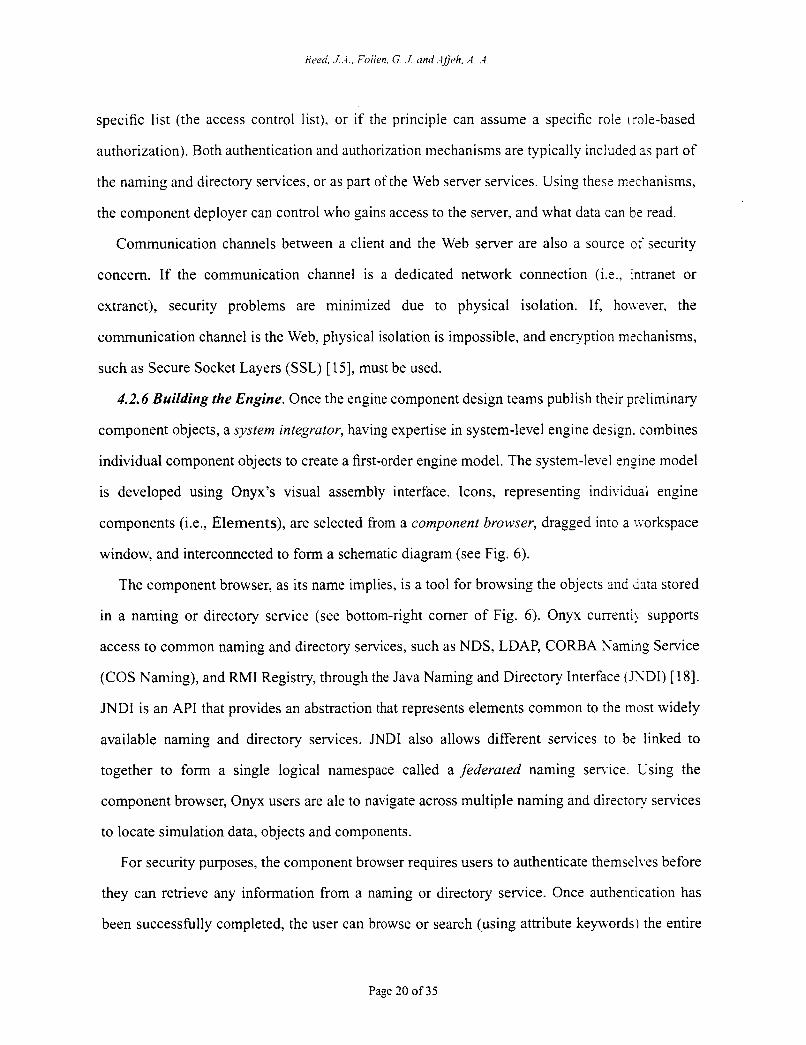
specific list (the access control list). or if the principle can assume a specific role (role-based
authorization). Both authentication and authorization mechanisms are typically included as part of
the naming and directory services, or as part of the Web server services. Using these mschanisms,
the component deployer can control who gains access to the server. and what data can be read.
Communication channels between a client and the Web server are also a source of security
concern. If the communication channel is a dedicated network connection (Le., intranet or
extranet), security problems are minimized due to physical isolation. If, hou wer, the
communication channel is the Web, physical isolation is impossible, and encryption mechanisms,
such as Secure Socket Layers (SSL) [ 151, must be used.
4.2.6 Building the Engine. Once the engine component design teams publish their preliminary
component objects, a system integrator, having expertise in system-level engine design. combines
individual component objects to create a first-order engine model. The system-level engine model
is developed using Onyx's visual assembly interface. Icons, representing individual engine
components (i.e., Elements), are selected from a component browser, dragged into a ivorkspace
window, and interconnected to form a schematic diagram (see Fig. 6).
The component browser, as its name implies, is a tool for browsing the objects and data stored
in a naming or directory service (see bottom-right comer of Fig. 6). Onyx current11 supports
access to common naming and directory services, such as NDS, LDAP, CORBA Xaming Service
(COS Naming), and Rh4I Registry, through the Java Naming and Directory Interface CJXDI) [ 181.
JNDI is an API that provides an abstraction that represents elements common to the most widely
available naming and directory services. JNDI also allows different services to be linked to
together to form a single logical namespace called a federated naming senice. Using the
component browser, Onyx users are ale to navigate across multiple naming and directory services
to locate simulation data, objects and components.
For security purposes, the component browser requires users to authenticate themselves before
they can retrieve any information from a naming or directory service. Once authentication has
been successfully completed, the user can browse or search (using attribute keywords) the entire
Page 20 of35
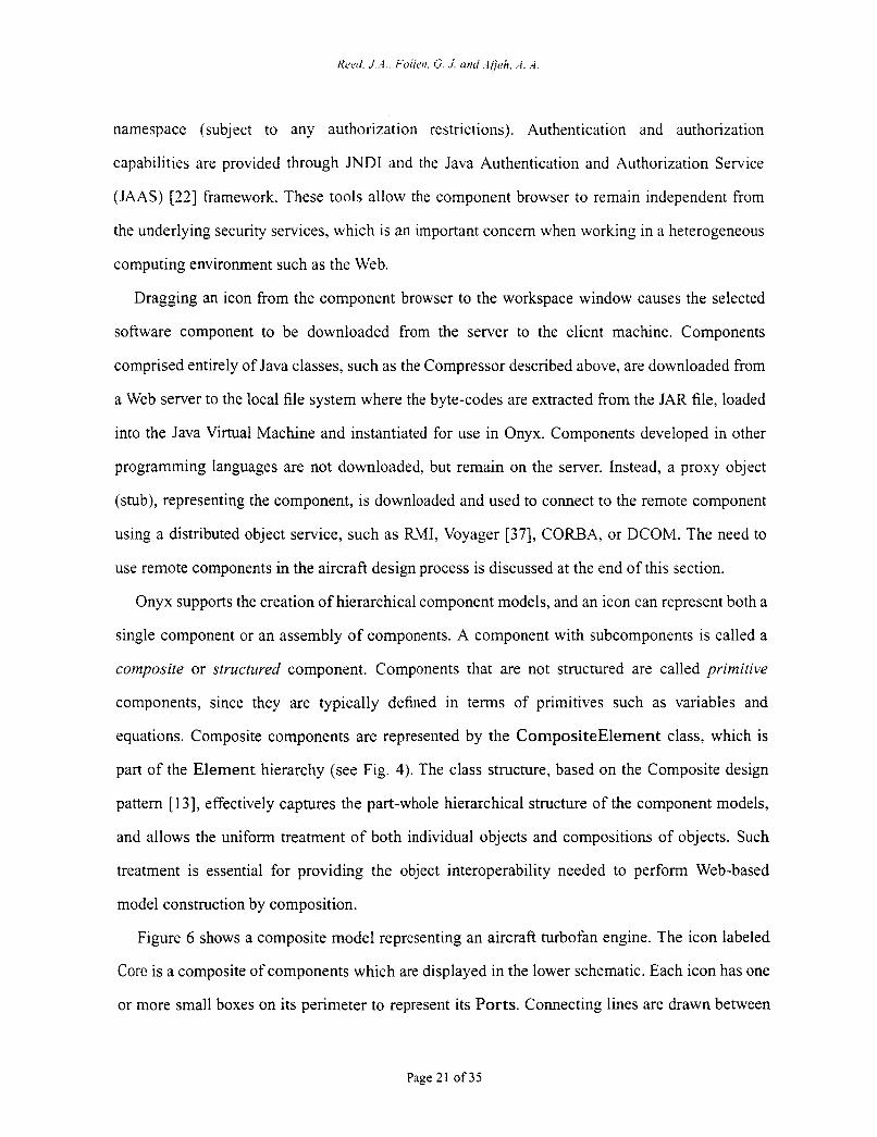
Reed. .j,.i., Foiiar. G. J'. unci djjch. :i. .'i.
namespace (subject to any authorization restrictions). Authentication and authorization
capabilities are provided through JN DI and the Java Authentication and Authorization Service
(JAAS) [22] framework. These tools allow the component browser to remain independent from
the underlying security services, which is an important concern when working in a heterogeneous
computing environment such as the Web.
Dragging an icon from the component browser to the workspace window causes the selected
software component to be downloaded from the server to the client machine. Components
comprised entirely of Java classes, such as the Compressor described above, are downloaded from
a Web server to the local file system where the byte-codes are extracted from the JAR file, loaded
into the Java Virtual Machine and instantiated for use in Onyx. Components developed in other
programming languages are not downloaded, but remain on the server. Instead, a proxy object
(stub), representing the component, is downloaded and used to connect to the remote Component
using a distributed object service, such as RMI, Voyager [37], CORBA, or DCOM. The need to
use remote components in the aircraft design process is discussed at the end of this section.
Onyx supports the creation of hierarchical component models, and an icon can represent both a
single component or an assembly of components. A component with subcomponents is called a
composite or structzired component. Components that are not structured are called primitive
components, since they are typically defined in terms of primitives such as variables and
equations. Composite components are represented by the CompositeElement class, which is
part of the Element hierarchy (see Fig. 4). The class structure, based on the Composite design
pattern [ 131, effectively captures the part-whole hierarchical structure of the component models,
and allows the uniform treatment of both individual objects and compositions of objects. Such
treatment is essential for providing the object interoperability needed to perform Web-based
model construction by composition.
Figure 6 shows a composite model representing an aircraft turbofan engine. The icon labeled
Core is a composite of components which are displayed in the lower schematic. Each icon has one
or more small boxes on its perimeter to represent its Ports. Connecting lines are drawn between
Page 21 of 35
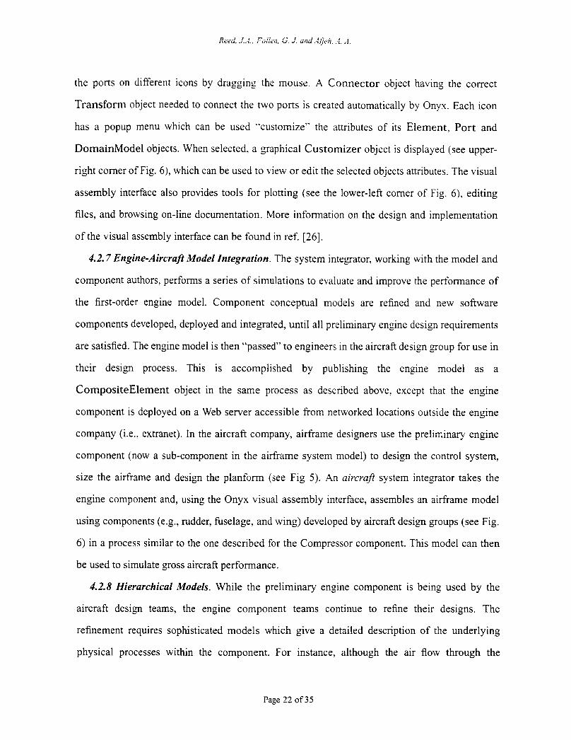
the ports on different icons by dragging the mouse. A Connector object having the correct
Transform object needed to connect the two ports is created automatically by Onyx. Each icon
has a popup menu which can be used ”customize” the attributes of its Element, Port and
DomainModel objects. When selected, a graphical Customizer object is displayed (see upper-
right comer of Fig. 61, which can be used to view or edit the selected objects attributes. The visual
assembly interface also provides tools for plotting (see the lower-left comer of Fig. 6), editing
files, and browsing on-line documentation. More information on the design and implementation
of the visual assembly interface can be found in ref. [ 2 6 ] .
4.2.7 Engine-AircrajI Model Integration. The system integrator, working with the model and
component authors, performs a series of simulations to evaluate and improve the performance of
the first-order engine model. Component conceptual models are refined and new software
components developed, deployed and integrated, until all preliminary engine design requirements
are satisfied. The engine model is then “passed” to engineers in the aircraft design group for use in
their design process. This is accomplished by publishing the engine model as a
CompositeElement object in the same process as described above, except that the engine
component is deployed on a Web server accessible from networked locations outside the engine
company (i.e.. extranet). In the aircraft company, airframe designers use the preliminary engine
component (now a sub-component in the airframe system model) to design the control system,
size the airframe and design the planform (see Fig 5). An aircraft system integrator takes the
engine component and, using the Onyx visual assembly interface, assembles an airframe model
using components (e.g., rudder, fuselage, and wing) developed by aircraft design groups (see Fig.
6) in a process similar to the one described for the Compressor component. This model can then
be used to simulate gross aircraft performance.
4.2.8 Hierarchical Models. While the preliminary engine component is being used by the
aircraft design teams, the engine component teams continue to refine their designs. The
refinement requires sophisticated models which give a detailed description of the underlying
physical processes within the component. For instance, although the air flow through the
Page 22 of 35
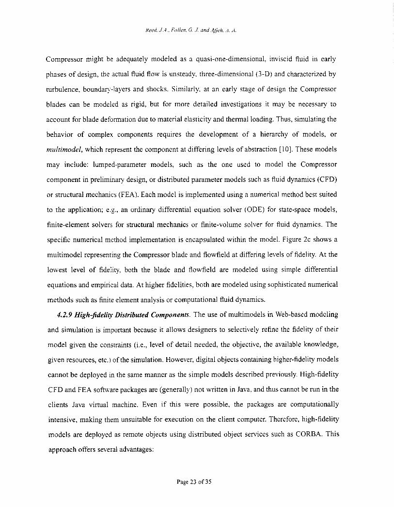
Compressor might be adequately modeled as a quasi-one-dimensional, inviscid fluid in early
phases of design, the actual fluid flow is unsteady. three-dimensional (3-D) and characterized by
turbulence, boundap-layers and shocks. Similarly. at an early stage of design the Compressor
blades can be modeled as rigid, but for more detailed investigations it may be necessary to
account for blade deformation due to material elasticity and thermal loading. Thus, simulating the
behavior of complex components requires the development of a hierarchy of models, or
multimodel, which represent the component at differing levels of abstraction [ 101. These models
may include: lumped-parameter models. such as the one used to model the Compressor
component in preliminary design, or distributed parameter models such as fluid dynamics (CFD)
or structural mechanics (FEA). Each model is implemented using a numerical method best suited
to the application; s.g, an ordinary differential equation solver (ODE) for state-space models,
finite-element solvers for structural mechanics or finite-volume solver for fluid dynamics. The
specific numerical method implementation is encapsulated within the model. Figure 2c shows a
multimodel representins the Compressor blade and flowfield at differing levels of fidelity. At the
lowest level of fidelity. both the blade and flowfield are modeled using simple differential
equations and empirical data. At higher fidelities, both are modeled using sophisticated numerical
methods such as finits element analysis or computational fluid dynamics.
4.2.9 High-fidelity Distributed Components. The use of multimodels in Web-based modeling
and simulation is important because it allows designers to selectively refine the fidelity of their
model given the constraints (i.e., level of detail needed, the objective, the available knowledge,
given resources, etc.) of the simulation. However, digital objects containing higher-fidelity models
cannot be deployed in the same manner as the simple models described previously. High-fidelity
CFD and FEA software packages are (generally) not written in Java, and thus cannot be run in the
clients Java virtual machine. Even if this were possible, the packages are computationally
intensive, making them unsuitable for execution on the client computer. Therefore, high-fidelity
models are deployed as remote objects using distributed object services such as CORBA. This
approach offers several advantages:
Page 23 of35
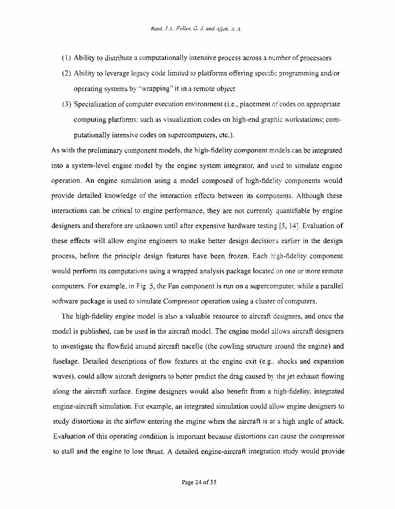
( 1 ) Ability to distribute a computationally intensive process across a number of processors
(2) Ability to leverage legacy code limited to platforms offering specific programming andor
operating systems by “wrapping” it in a remote object
(3) Specialization of computer execution environment (i.e., placement of codes on appropriate
computing platforms: such as visualization codes on high-end graphic workstations; com-
putationally intensive codes on supercomputers, etc.).
As with the preliminary component models, the high-fidelity component models can be integrated
into a system-level engine model by the engine system integrator, and used to simulate engine
operation. An engine simulation using a model composed of high-fidelity components would
provide detailed knowledge of the interaction effects between its components. Although these
interactions can be critical to engine performance, they are not currently quantifiable by engine
designers and therefore are unknown until after expensive hardware testing [ 5 , 141. Evaluation of
these effects will allow engine engineers to make better design decisions earlier in the design
process, before the principle design features have been frozen. Each high-fidelity component
would perform its computations using a wrapped analysis package located on one or more remote
computers. For example. in Fig. 5 , the Fan component is run on a supercomputer. while a parallel
software package is used to simulate Compressor operation using a cluster of computers.
The high-fidelity engine model is also a valuable resource to aircraft designers, and once the
model is published, can be used in the aircraft model. The engine model allows aircraft designers
to investigate the flowfield around aircraft nacelle (the cowling structure around the engine) and
fbselage. Detailed descriptions of flow features at the engine exit (e.g.. shocks and expansion
waves), could allow aircraft designers to better predict the drag caused by the jet exhaust flowing
along the aircraft surface. Engine designers would also benefit from a high-fidelity, integrated
engine-aircraft simulation. For example, an integrated simulation could allow engine designers to
study distortions in the airflow entering the engine when the aircraft is at a high angle of attack.
Evaluation of this operating condition is important because distortions can cause the compressor
to stall and the engine to lose thrust. A detailed engine-aircraft integration study would provide
Page 24 of 35
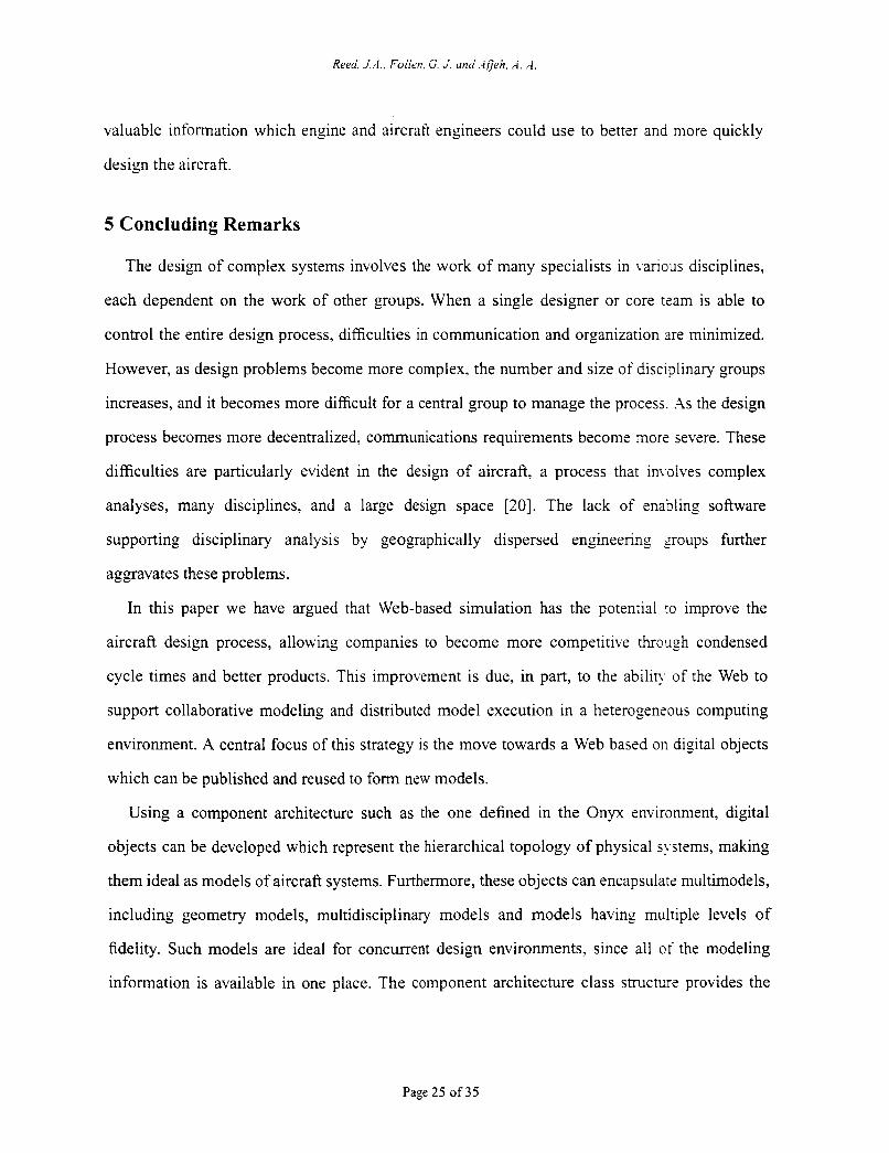
valuable information which engine and aircraft engineers could use to better and more quickly
design the aircraft.
5 Concluding Remarks
The design of complex systems involves the work of many specialists in Lanous disciplines,
each dependent on the work of other groups. When a single designer or core tzam is able to
control the entire design process, difficulties in communication and organization are minimized.
However, as design problems become more complex, the number and size of disciplinary groups
increases, and it becomes more difficult for a central group to manage the process. As the design
process becomes more decentralized. communications requirements become more severe. These
difficulties are particularly evident in the design of aircraft, a process that in\ olves complex
analyses, many disciplines, and a large design space [20]. The lack of enabling software
supporting disciplinary analysis by geographically dispersed engineering groups further
aggravates these problems.
In this paper we have argued that Web-based simulation has the potential 10 improve the
aircraft design process, allowing companies to become more competitive through condensed
cycle times and better products. This improvement is due, in part, to the abilin. of the Web to
support collaborative modeling and distributed model execution in a heterogenzous computing
environment. A central focus of this strategy is the move towards a Web based on digital objects
which can be published and reused to form new models.
Using a component architecture such as the one defined in the Onyx environment, digital
objects can be developed which represent the hierarchical topology of physical systems, making
them ideal as models of aircraft systems. Furthermore, these objects can encapsulate multimodels,
including geometry models, multidisciplinary models and models having multiple levels of
fidelity. Such models are ideal for concurrent design environments, since all of the modeling
information is available in one place. The component architecture class structure provides the

Reed, J . A . , Follen, G. J. and.-lJeii. A. ‘-1
capability to wrap existing software packages. This is extremely important in providing
collaborative and integrative environment for the aircraft design process.
A World-Wide Web populated with digital objects provides the foundation for modeling by
composition. Onyx’s component architecture defines the standard interfaces needed to
dynamically compose new objects and the visual assembly interface makes composition simple
and easy. This promotes model reuse, as well as reducing new model development time.
The Onyx environment supports the distribution of simulation models across the Web. Both
Web-based model distribution (in the case of Java-based models) and distributed services
approaches (e.g., CORBA, COM) are provided. Each of these increase Onyx’s usability, as
models can be placed virtually anywhere. The C O M A bindings make it possible to integrate non-
Java language distributed objects and legacy code. Also, since Onyx is written entirely in Java, it
is portable without modifications to any computing platform which supports the Java Virtual
Machine. Heterogeneous computing support makes the Onyx Web-based simulation system
extremely viable for use in the heterogeneous computing environments typical of aircraft
companies. Most importantly, it allows access to existing legacy codes and access to codes which
must operate on specific architectures or operating systems.
References
Arnold, K. and Gosling, J., 1996, The Java Programming Language, Addison Wesley
Publishing Company, Inc., Reading, MA.
Berners-Lee, T., 1996, “WWW: Past, Present, and Future,” Computer, 29( 10) p. 69.
Birtwistle, G., Dahl, O., Myhrhaug, B. and Nygaard, K., 1973, Simula begin. Petrocelli
Charter, New York.
Cardelli, L., 1994, “Obliq: A Language with Distributed Scope,” Research Report 122,
Digital Equipment Corporation Systems Research Center, Palo Alto, C.4. On-line
document. Available at http://gatekeeper.dec.com/pub/DEC/SRC/research-reports/abstracts/src-rr-
122. html.
Claus, R. W., Evans, A. L., Lytle, J. K., and Nichols, L. D., 1991, “Numerical Propulsion
Page 26 of35
Reed, j . 4 . . Foiien. G. .I. und.-ijjeh, .i. A
System Simulation,” Computing Systems in Engineering, Vol. 2, pp. 357-364
Eddon, G. and Eddon, H., 1998, Inside Distributed COiLl, Microsoft Press, Redmond,
Washington.
Englander, R., 1997, Developing Java Beans, O’Reilly & Associates, Inc., Sebastopol, CA.
Fishwick, P.A., 1996, “Web-Based Simulation: Some Personal Observations,” Proceedings
of the 1996 Winter Simulation Conjerence, J.M. Charnes, D.J. Momce, D.T. Brunner and
J.J. Swaim (eds.), pp. 772-779, Coronado, CA.
Fishwick, P.A., 1998, “Issues with Web-Publishable Digital Objects,” Proceedings of SPIE:
Enabling Technologies for Simulation Science II, pp. 136-142, Orlando, FL, April 14-16.
[ 101 Fishwick P. A. and Zeigler, B. P., 1992, “A Multimode1 Methodology for Qualitative Model
Engineering,” ACM Transactions on Modeling and Computer Simulation, Vol. 12, pp. 52-
81.
[6]
[7]
[8]
[9]
[ l l ] Fishwick, P.A., Hill, D.R.C. and Smith, R., Eds., 1998, Proceedings of the 1998
International Conference on Web-Based Modeling and Simulation. SCS Simulation Series
30( 1).
[12] Freeman, E., Hupfer, S., and Arnold, K., 1999, JavaSpaces*“ Principles, Patterns, and
Practice, Addison- Wesley.
[13] Gamma, E., Helm, R, Johnson, R., and Vlissides, J., 1995, Design Patterns: Elements of
Reusable Object-Oriented Software, Addison Wesley Publishing Company, Inc., Reading,
MA.
[14] Hall, E.J., Delaney, R.A., Lynn, S.R. and Veres, J.P., 1998, “Energy Efficient Engine Low
Pressure Subsystem Aerodynamic Analysis,” AIAA Paper No. 98-3 1 19.
[ 151 Hickman, K.E.B., 1995, The SSL Protocol. Available at http://home.netscape.com/eng/security/ SSL-2.html.
[16] Housley, R., Ford, W., Polk, T., and Solo, D., 1999, “Internet X.509 Public Key
Infrastructure Certificate and CRL Profile. Request for Comments 2459,” Internet
Engineering Task Force. Available at http://www.imc.org/rfc2459 . [ 171 Jameson, A., 1997, “Re-Engineering the Design Process through Computation,” AIAA
Paper No. 97-0641.
[ 181 Java Naming and Directory Interface. Available at http:/ljava.sun.com/productsljndi/index.html.
[19] Johnson R. E. and Foote, B., 1988, “Designing Reusable Classes, The Journal Of Object-
Page 27 of 35
Oriented Programming,” 1(2), pp. 22-35.
[20] Kroo. I., Alms, S., Braun, R.. Gage, P., and Sobieski, I., 1994. “Multidisciplinary
Optimization Methods for Aircraft Preliminary Design,” AIAA Paper No. 94-4325.
[21] Kuhl, F., Weatherly, R. and Dahmann. J., 1999, Creating Computer Simulation Systems: An
Introduction to the High Level Architecture, Prentice Hall.
[22] Lai, C., Gong, L., Koved, L., Nadalin, A. and Schemers, R. 1999, “User Authentication And
Authorization In The JavaTM Platform,” To appear in Proceedings of the 15th Annual
Computer Security Applications Conference, Phoenix, AZ.
[23] Lindberg, K.J.P., 1998, Novell’s iVetware 5 Administrator’s Handbook, IDG Books
Worldwide.
[24] Neuman, B.C. and Ts’o, T., 1994, “Kerberos: An Authentication Service for Computer
Networks,” IEEE Communications, 32(9), pp.33-38.
[25] Page. E.H. and Opper, J.M., 1999, “Investigating the Application of Web-Based Simulation
Principles within the Architecture for a Next-Generation Computer Generated Forces
Model.” Future Generation Computer Svstems, to appear.
[26] Reed. J.A., 1998, “Onyx: An Object-Oriented Framework for Computational Simulation of
Gas Turbine Systems,” Ph.D. dissertation, The University of Toledo, Toledo, Ohio.
[27] Reed. J.A., and Afjeh, A.A., 1998, “An Object-Oriented Framework for Distributed
Computational Simulation of Aerospace Propulsion Systems,” Proceedings of the 4th
USE-YIX Conference on Object-Oriented Technologies and S,vstems (COOTS), Santa Fe,
New Mexico.
[28] Ridlon, S. A., 1996, “A Software Framework for Enabling Multidisciplinary Analysis and
Optimization,” AIAA Paper No. 96-4133.
[29] Rogerson, D., 1996, h i d e COM, Microsoft Press, Redmond, Washington.
[30] Schatz. B.R., and Hardin, J.B., 1994, “NCSA Mosaic and the World Wide Web: Global
Hypermedia Protocols for the Internet,” Science, 265, p. 895.
[31] Schmidt, D. C., 1997, “Applying Design Patterns and Frameworks to Develop Object-
Oriented Communications Software,” Handbook of Programming Languages, Volume I, P.
Salus, ed., MacMillian Computer Publishing.
[32] Smith. R.B., and Ungar, D., 1995, “Programming as an Experience: The Inspiration for
Self,” Proceedings of ECOOP’95.
Page 28 of35
Reed. J..4.. Foiien. G. J-. ann“.ijjen, i. .d
[33] Watters, A., van Rossum, G.. and Xhlstrom, J., 1996, Internet Programming with Python,
MIS PressiHenry Holt Publishers.
[34] Wirth, N. and Gutknecht, J., 1989, ”The Oberon System,” Software: Updated Practice and
Experience, 19(9), p. 857.
[35] Wollrath, A., kggs, R. and Waldo. J., 1996, “‘A Distributed Object Model for the JavaTM
System,” Proceedings of the Second USENIX Conference on Object-Oriented Technology
and Systems (COOTS), pp. 2 19-23 1.
[36] Vinoski, S, 1997, “CORBA: Integrating Diverse Applications Within Distributed
Heterogeneous Environments,” I€€€ Communications, 35(2), pp. 46-55.
[37] Voyager, 1997, “Voyager: The Agent ORB for Java” Online document. Available at http://
w,objectspace.com/.
[38] Yeong, W., Howes, T., and S. Kille, “Lightweight Directory Access Protocol”, Request For
Comments 1777.” Internet Engineering Task Force. Available at http://www.ietf.org/rfc/
rfcl777.txt.
[39] Zimmerman. P. 1994, PGP User’s Guide, MIT Press, Cambridge, 1994.
Page 29 of 35
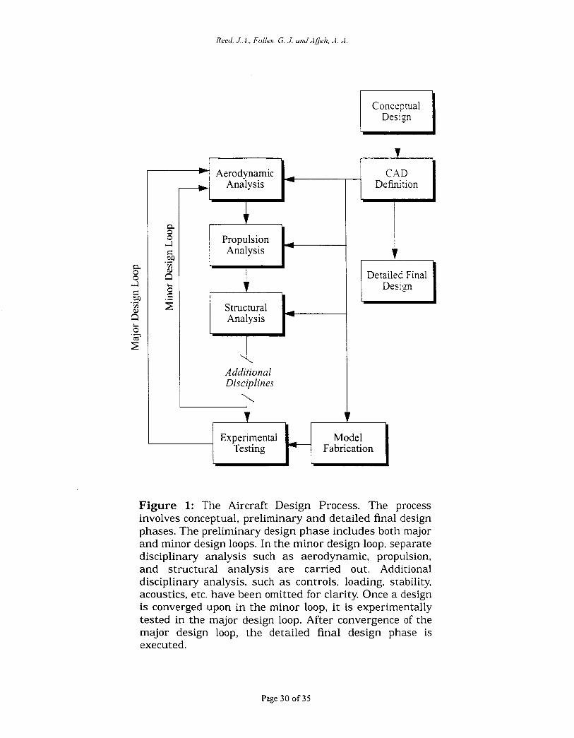
t h Aerodynamic
f
Structural Analysis
Additional Disciplines +-
I Concepal Design
FI Deht ion
I Detailed Final Design
I Model k Fabrication Experimental
Testing
Figure 1: The Aircraft Design Process. The process involves conceptual, preliminary and detailed final design phases. The preliminary design phase includes both major and minor design loops. In the minor design loop, separate disciplinary analysis such as aerodynamic, propulsion, and structural analysis are carried out. Additional disciplinary analysis, such as controls, loading, stability, acoustics, etc. have been omitted for clarity. Once a design is converged upon in the minor loop, i t is experimentally tested in the major design loop. After convergence of the major design loop, the detailed final design phase is executed.
Page 30 of 35
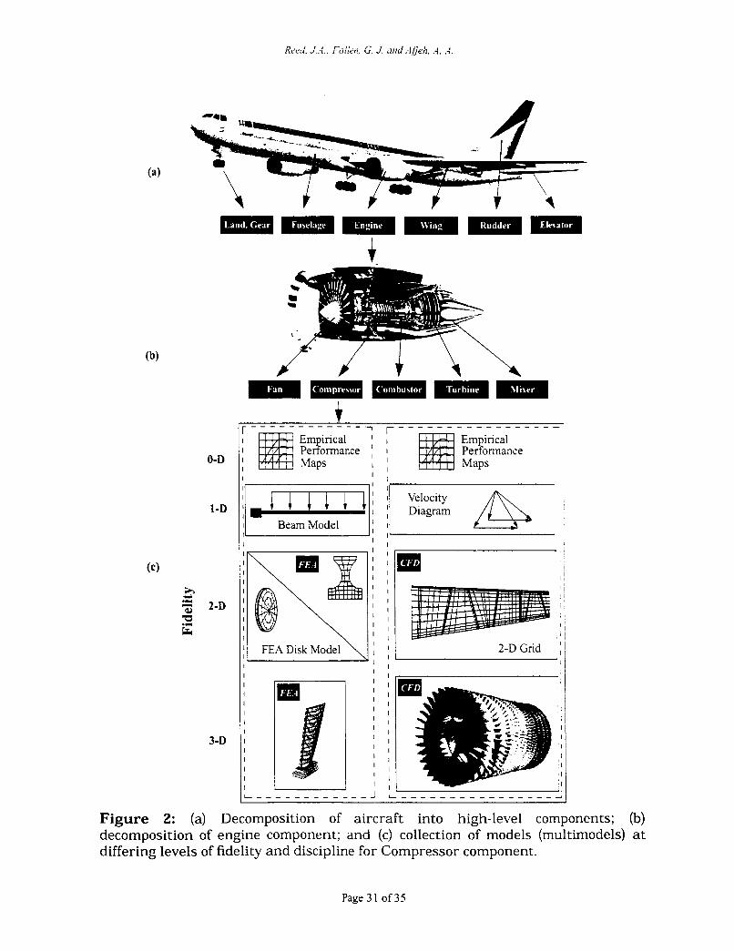
0-D
1-D
h a 2-D Y .II I
3-D
I I
, I .,
I
I I Velocity : m l m l I : I Diagram
Beam Model I I I I I
I I I I I
I I I I
I 1 2-D Grid ' 1 I 1 I I
FEA Disk Model
Figure 2: (a) Decomposition of aircraft into high-level components; (b) decomposition of engine component; and (c) collection of models (multimodels) at differing levels of fidelity and discipline for Compressor component.
Page 3 1 of 35
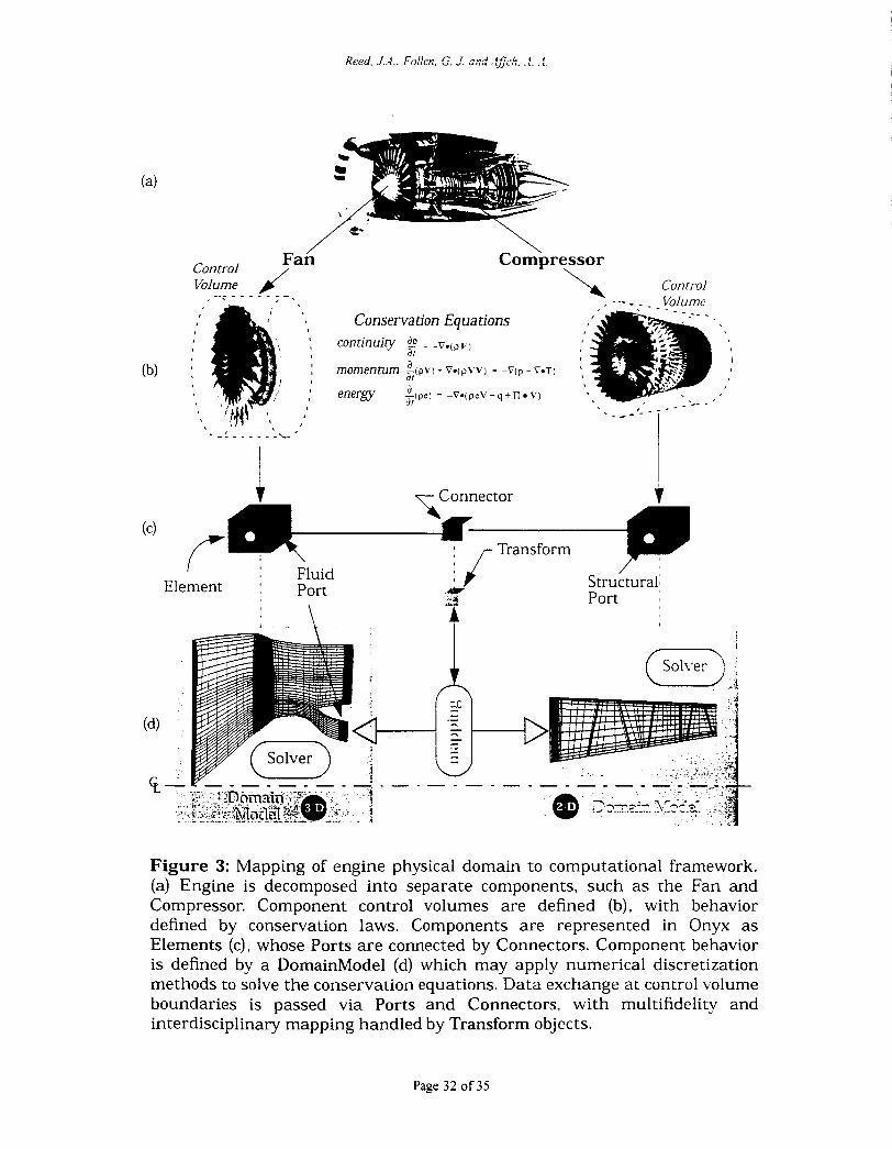
/ e Fan Control / Compressor
\
'\ Control
- .- - - Volume Volume I . -. - - - - - J I ' - \ Conservation Equations
continuity aP = -v.(pV)
momentum -(pv) - v.(pvv) = - v ( p - VOT)
energy
1 at a at a ;Illpel = -v.(prv - q A n v)
,
: Fluid I Element : Port
' . : \
/
Structural: Port
. . . - - - - - - - - : ---:: @ Z?-.?:--. . 5..?C...,. r - - --.-
Figure 3: Mapping of engine physical domain to computational framework. (a) Engine is decomposed into separate components, such as the Fan and Compressor. Component control volumes are defined (b), with behavior defined by conservation laws. Components are represented in Onyx as Elements (c), whose Ports a r e connected by Connectors. Component behavior is defined by a DomainModel (d) which may apply numerical discretization methods to solve the conservation equations. Data exchange at control volume boundaries is passed via Ports and Connectors, with multifidelity and interdisciplinary mapping handled by Transform objects.
Page 32 of 35
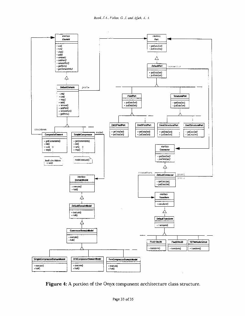
interface E l m m I
+ init0 + run0 + stopo + add0 + remove0 + addFtxrO + remreR~rf0 + ger&uO + gerElemen/lnfoO
I
4
I
171
I*l po r t s I + In#o
t rum + stop0 i add0 i remove0 t addPofl0 + remotePortO t getPons0
+ gecDataSal:
h- n- ch i ld ren
model
t gerElemenIlnfo0 t inn0 truno o interface I Conneaw 1- + runQ o
t stopo ;
forall c in children 1 model.execute0; L F L , Lj I
4 interface
DanuiHodcl t getDataSet0
interface Lm I t execute0 I + hait0
CwressorDoMnModd -h- I + execute0 I t haHO
Figure 4: A portion of the Onyx component architecture class structure.
Page 33 of35
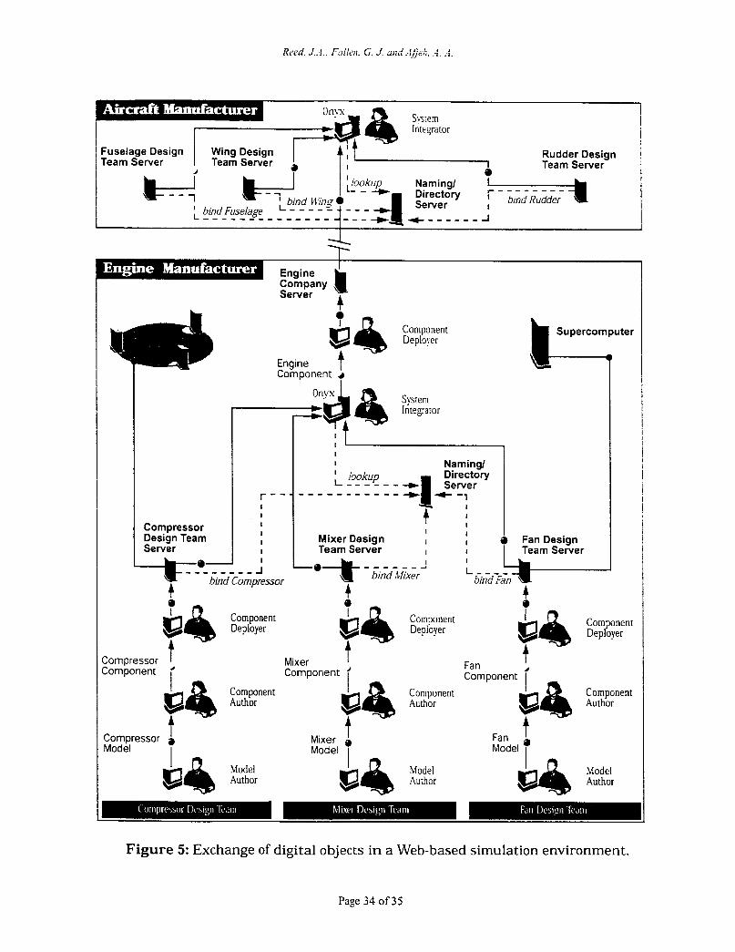
Rudder Design Team Server
Naming/
bind Wing Server - - - - - 4- - - - 1 bu7dFuselage - - - - - - - - - - - - - - - - - -
Engine Company Server 4
I
Deployer
Engine Component 4
I
Supercomputer L
r - -
Design Team Compressor
Server
bind Compressor
I -
I Naming/ I lookup Directory I - - - - - - - - - - - - - - - - _ _
I I
I : I 1
Mixer Design I 1 0 FanDesign Team Server I I I Team Server
4 A e
Figure 5: Exchange of digital objects in a Web-based simulation environment.
Page 34 of35
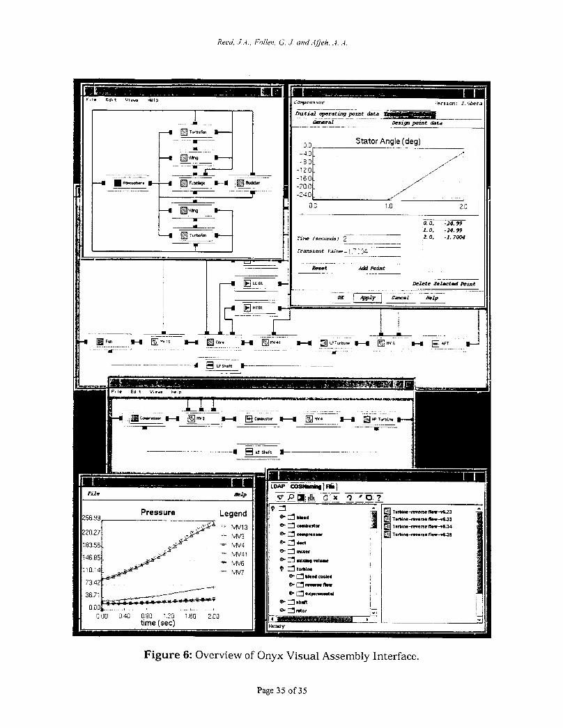
~~ ~~~
Figure 6: Overview of Onyx Visual Assembly Interface.
Page 35 of35