


OBDLink® Family Reference and Programming Manual (FRPM) · Reference and Programming Manual...
59
OBDLink® Family Reference and Programming Manual (FRPM)
Transcript of OBDLink® Family Reference and Programming Manual (FRPM) · Reference and Programming Manual...

OBDLink Family
2 of 59 www.obdsol.com OBDLinkFRPMC
Table of Contents
1.0 Overview .......................................................................................................................................................... 4 2.0 Objective of This Manual ................................................................................................................................. 4 3.0 OBDLink Product Family .................................................................................................................................. 4
3.1 OBDLink Devices ........................................................................................................................................ 4 3.2 OBDLink ICs ................................................................................................................................................ 5
4.0 Feature Highlights ............................................................................................................................................ 5 5.0 Typical Applications ......................................................................................................................................... 5 6.0 Communicating with the OBDLink ................................................................................................................... 6 7.0 AT Commands ................................................................................................................................................. 7
7.1 AT Command Summary .............................................................................................................................. 7 7.2 AT Command Descriptions ........................................................................................................................ 10 7.3 Programmable Parameters ....................................................................................................................... 17
8.0 ST Commands ............................................................................................................................................... 20 8.1 ST Command Summary ............................................................................................................................ 20 8.2 General ST Commands ............................................................................................................................. 24 8.3 UART Specific ST Commands .................................................................................................................. 24 8.4 Device ID ST Commands .......................................................................................................................... 26 8.5 Voltage ST Commands ............................................................................................................................. 27 8.6 OBD Protocol ST Commands .................................................................................................................... 27 8.7 ISO Specific ST Commands ...................................................................................................................... 29 8.8 CAN Specific ST Commands .................................................................................................................... 30 8.9 Monitoring ST Commands ......................................................................................................................... 31 8.10 Filtering ST Commands ............................................................................................................................. 31 8.11 PowerSave ST Commands ....................................................................................................................... 33 8.12 Bluetooth Specific Commands .................................................................................................................. 36 8.13 General Purpose I/O ST Commands ........................................................................................................ 36
9.0 Error Messages .............................................................................................................................................. 38 10.0 OBD Requests ............................................................................................................................................... 40 11.0 OBD Message Filtering .................................................................................................................................. 40
11.1 Non-CAN Protocols ................................................................................................................................... 40 11.2 CAN Protocols ........................................................................................................................................... 41
12.0 ISO 15765 Message Reception ..................................................................................................................... 43 13.0 CAN Addressing Formats .............................................................................................................................. 45
13.1 Normal ....................................................................................................................................................... 45 13.2 Normal fixed............................................................................................................................................... 45 13.3 Extended .................................................................................................................................................... 45 13.4 Mixed ......................................................................................................................................................... 45
14.0 SAE J1939 ..................................................................................................................................................... 46 15.0 PowerSave Functionality ............................................................................................................................... 50
15.1 Control Modes ........................................................................................................................................... 50 15.1.1 Native PowerSave Mode .................................................................................................................. 50 15.1.2 ELM327 Low Power Mode ................................................................................................................ 50
15.2 Sleep Triggers ........................................................................................................................................... 50 15.2.1 STSLEEP and ATLP Commands ..................................................................................................... 50 15.2.2 UART Inactivity ................................................................................................................................. 51 15.2.3 External SLEEP Input ....................................................................................................................... 51 15.2.4 Voltage Level Sleep .......................................................................................................................... 51
15.3 Wakeup Triggers ....................................................................................................................................... 51 15.3.1 UART Rx Pulse Wakeup................................................................................................................... 52 15.3.2 External SLEEP Input Wakeup ......................................................................................................... 52 15.3.3 Voltage Level Wakeup ...................................................................................................................... 52 15.3.4 Voltage Change Wakeup .................................................................................................................. 52
15.4 Voltage Trigger Considerations ................................................................................................................. 52 15.5 External Power Control Output .................................................................................................................. 53 15.6 Device Specific Details .............................................................................................................................. 53
15.6.1 OBDLink Hardware Rev 1.x .............................................................................................................. 53

Reference and Programming Manual
OBDLinkFRPMC www.obdsol.com 3 of 59
15.6.2 OBDLink Hardware Rev 2.0–2.4 ...................................................................................................... 53 15.6.3 OBDLink Hardware Rev 2.5 and Above ........................................................................................... 54 15.6.4 OBDLink S ........................................................................................................................................ 54 15.6.5 OBDLink SX Rev 1.x ......................................................................................................................... 54 15.6.6 OBDLink SX Rev 2.x ......................................................................................................................... 54 15.6.7 OBDLink SX Rev 3.x ......................................................................................................................... 54 15.6.8 OBDLink MX Bluetooth ..................................................................................................................... 54 15.6.9 OBDLink MX Wi-Fi ............................................................................................................................ 54 15.6.10 microOBD 200 .................................................................................................................................. 54 15.6.11 STN1110, STN1170, STN2100, and STN2120 ................................................................................ 55
15.7 Sleep/Wakeup Trigger Summary .............................................................................................................. 55 Appendix A: Revision History ................................................................................................................................ 57 Appendix B: Contact Information ........................................................................................................................... 59
TO OUR VALUED CUSTOMERS
It is our intention to provide our valued customers with the best documentation possible to ensure successful use of your OBD Solutions products. To this end, we will continue to improve our publications to better suit your needs. Our publications will be refined and enhanced as new volumes and updates are introduced.
Most Current Data Sheet To obtain the most up-to-date version of this OBDLink Family Reference and Programming Manual, please visit our web site at
http://www.obdsol.com
You can determine the version by examining its literature number found on the bottom outside corner of any page. The last character of the
literature number is the version number, (e.g., OBDLinkFRPMA is version A of document OBDLinkFRPM).
All rights reserved. Copyright © 2019 OBD Solutions LLC Every effort is made to verify the accuracy of information provided in this document, but no representation or warranty can be given, and no liability assumed by OBD Solutions with respect to the accuracy and/or use of any products or information described in this document. OBD Solutions will not be responsible for any patent infringements arising from the use of these products or information and does not authorize or warrant the use of any OBD Solutions product in life support devices and/or systems. OBD Solutions reserves the right to make changes to the device(s) described in the document in order to improve reliability, function, or design.

OBDLink Family
4 of 59 www.obdsol.com OBDLinkFRPMC
1.0 Overview On-Board Diagnostics, Second Generation (OBD-II)
is a set of standards for implementing a computer-based system to control emissions from vehicles. It was first introduced in the United States in 1994 and became a requirement on all 1996 and newer US cars and light trucks. Other countries, including Canada, parts of the European Union, Japan, Australia, and Brazil adopted similar legislation. A large portion of the modern vehicle fleet supports OBD-II or one of its regional variants.
Among other things, OBD-II requires that each compliant vehicle be equipped with a standard diagnostic connector (DLC) and describes a standard way of communicating with the vehicle’s computer, also known as the ECU (Electronic Control Unit). A
wealth of information can be obtained by tapping into the OBD bus, including the status of the malfunction indicator light (MIL), diagnostic trouble codes (DTCs), inspection and maintenance (I/M) information, freeze frames, VIN, hundreds of real-time parameters, and more.
The OBDLink family of devices is a set of OBD to UART interpreters that can be used to convert messages between any of the OBD-II protocols currently in use (as well as some proprietary OBD protocols) and UART. They are fully compatible with the de facto industry standard ELM327 command set. Based on a 16-bit processor core, the OBDLink devices offer more features and better performance than any other ELM327 compatible IC.
2.0 Objective of This Manual This manual describes the architecture, features,
and the command set of the OBDLink family of OBD interpreters.
Note that not all commands, protocols, and features are supported by all devices. You should consult the respective device’s data sheet for device-specific details, such as:
• List of supported protocols and features
• Pinout and packaging details
• Device-specific electrical specifications and characteristics
• Reference schematics
3.0 OBDLink Product Family
3.1 OBDLink Devices
Device ID
Status Product Name Description
STN1000 Obsolete OBDLink CI CAN/ISO/KWP to USB
STN1100 OoP(1) OBDLink OBD to USB with optional Bluetooth or Wi-Fi add-on modules
STN1101 OoP(1) OBDLink S OBD to RS232
STN1120 OoP(1) microOBD 200 OBD to UART interface in a DIP-24 package
STN1130 Active OBDLink SX Low cost OBD to USB
STN1150 OoP(1) OBDLink MX Bluetooth OBD to Bluetooth with support for MS CAN and SW CAN
STN1151 Active OBDLink MX Bluetooth OBD to Bluetooth with support for MS CAN and SW CAN, version 2.0
STN1152 Active OBDLink MX Wi-Fi OBD to Wi-Fi with support for MS CAN and SW CAN
STN1155 Active OBDLink LX Bluetooth OBD to Bluetooth
STN2230 Active OBDLink EX Low cost OBD to USB with support for MS CAN and (optional) SW CAN
STN2255 Active OBDLink MX+ OBD to Bluetooth with support for MS CAN and SW CAN with support for iOS devices
Note 1. Out of production

Reference and Programming Manual
OBDLinkFRPMC www.obdsol.com 5 of 59
3.2 OBDLink ICs
Device ID
Status Product Name Description
STN1110 NRND(1) STN1110 OBD to UART interpreter
STN1170 NRND(1) STN1170 OBD to UART interpreter with support for MS CAN and SW CAN
STN2100 Active STN2100 OBD to UART interpreter
STN2120 Active STN2120 OBD to UART interpreter with support for MS CAN and SW CAN
Note 1. In Production, not recommended for new designs
4.0 Feature Highlights • Fully compatible with the ELM327 AT command set
• Feature-rich parallel extended ST command set
• UART baud rates from 38 bps to 10 Mbps1
• Large (up to 4KB) data transfers2
• Safe, secure bootloader for easy firmware updates
• Support for all legislated OBD-II protocols: o ISO 15765 (CAN) o ISO 14230 (Keyword Protocol 2000, KWP2K) o ISO 9141 (Asian, European, Chrysler vehicles) o SAE J1850 VPW (GM vehicles) o SAE J1850 PWM (Ford vehicles) o SAE J1939 (Heavy Duty vehicles)
• Support for non-legislated protocols (not available in all devices): o ISO 11898 (raw CAN) o SAE J2818 o SAE J2411 (GMW3089, Single Wire CAN, GMLAN) o Ford MS-CAN (Medium Speed CAN)
• Superior automatic protocol detection algorithm
• Large memory buffer
• Voltage input for battery monitoring
• PowerSave mode with multiple sleep and wakeup triggers
Note 1: Maximum theoretical baud rate. Actual maximum baud rate is application dependent and may be limited by driver hardware.
Note 2: Only available on specific OBDLink devices.
5.0 Typical Applications • Fleet management and tracking applications
• Usage-based auto insurance
• Telematics
• Automotive diagnostic scan tools and code readers
• OBD data collection
• ECU reflashing

OBDLink Family
6 of 59 www.obdsol.com OBDLinkFRPMC
6.0 Communicating with the OBDLink The OBDLink uses a three-wire UART connection
that is CMOS/TTL compatible. The default UART settings are:
• Baud rate: o ICs and modules: 9600 bps o OBD adapters: 115200 bps
• 8 data bits
• No parity bit
• One stop bit The baud rate can be changed in software (see
STSBR). Once powered and connected, the OBDLink will
display the startup message: ELM327 v1.3a > The OBDLink sends the ‘>’ (“prompt”) character, to
signal that it is ready for more input. User software should always wait for the prompt before sending the next command.
There are three types of commands recognized by the OBDLink: AT commands, ST commands, and OBD requests.
The OBDLink is designed to fully emulate the ELM327 AT command set supported by many existing OBD software applications. AT commands begin with “AT” and are intended for the IC. They cause the OBDLink to carry out some action – change or display settings, perform a reset, and so on. A list of supported AT commands, and their descriptions can be found in Section 7.0.
To provide additional functionality while maintaining compatibility with the ELM327 command set, the OBDLink supports a parallel ST command set, described in Section 8.0.
OBD requests are messages that are transmitted on the OBD bus. Only ASCII hexadecimal digits (0-9 and A-F) are allowed in OBD requests.
Only ASCII alpha characters, numbers, backspaces, and the carriage return are accepted on the UART, spaces are ignored. All commands must terminate with a carriage return (0x0D).
By default, responses from the OBDLink are terminated with a carriage return (0x0D). ATL1 command can be used to have the OBDLInk append line feeds (0x0A) to the carriage returns.
Sending a single carriage return character repeats the last command.

Reference and Programming Manual
OBDLinkFRPMC www.obdsol.com 7 of 59
7.0 AT Commands AT commands cause the OBDLink to carry out
some action (e.g., print device description or reboot) or change the default settings (turn echo off, change message header bytes, etc). Every effort was made to maintain compatibility with legacy ELM327 software,
and with few exceptions, the AT commands work exactly as they would on the ELM327.
Section 7.1 is a summary of all available AT commands. For detailed descriptions of each command, see Section 7.2.
7.1 AT Command Summary AT commands in this section are grouped by
function, for quick reference. The ‘Status’ column indicates the level of support for each command:
• supported: this command is available
• deprecated: this command is supported for backwards compatibility, but its use is discouraged because it serves no useful purpose on the OBDLink (e.g., ATFE) or because a superior alternative exists.
Typically, the alternative is an ST command that is more powerful, flexible, or easier to use. See the command’s description (in Section 7.2) for more information.
• not yet supported: this command will be available in the near future
Asterisk (*) next to a setting means it’s the default value.
Table 1 – General AT Commands
Command Description Status
<CR> Repeat last command supported
ATBRD divisor Try baud rate divisor divisor deprecated
ATBRT timeout Set baud rate timeout deprecated
ATD Set all settings to defaults supported
ATE 1|0 Echo on*/off supported
ATFE Forget events deprecated
ATI Print ELM327 version ID string supported
ATL 1|0 Line feeds on/off* supported
ATLP Enter low power mode deprecated
ATM 1|0 Memory on*/off supported
ATRD Read the stored data byte supported
ATSD hh Save data byte hh supported
ATWS Warm start supported
ATZ Reset device supported
AT@1 Display device description supported
AT@2 Display device identifier supported
AT@3 cccccccccccc Store device identifier supported
Table 2 – Programmable Parameter AT Commands
Command Description Status
ATPP xx OFF Disable PP xx supported
ATPP xx ON Enable PP xx supported
ATPP xx SV yy For PP xx, set value to yy supported
ATPPS Print PP summary supported
OBDLink Family
8 of 59 www.obdsol.com OBDLinkFRPMC
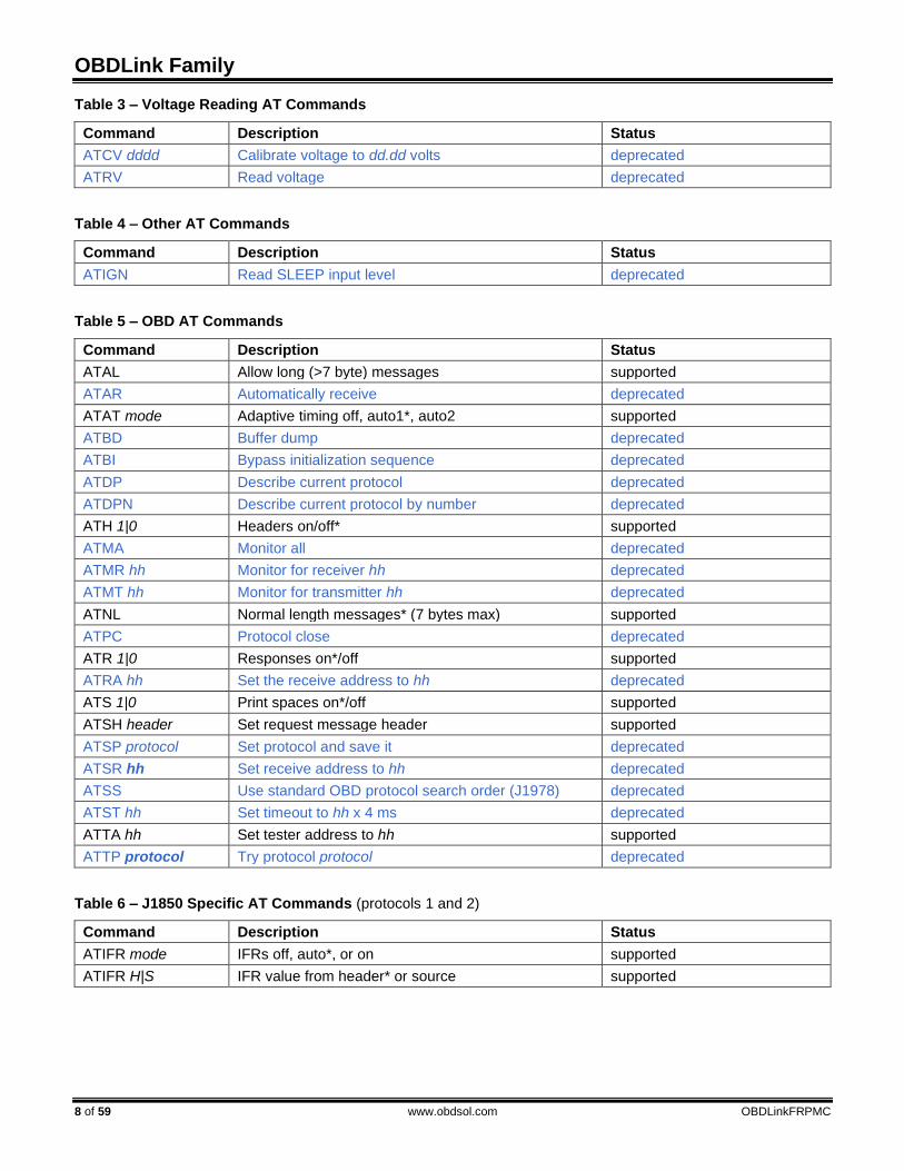
Table 3 – Voltage Reading AT Commands
Command Description Status
ATCV dddd Calibrate voltage to dd.dd volts deprecated
ATRV Read voltage deprecated
Table 4 – Other AT Commands
Command Description Status
ATIGN Read SLEEP input level deprecated
Table 5 – OBD AT Commands
Command Description Status
ATAL Allow long (>7 byte) messages supported
ATAR Automatically receive deprecated
ATAT mode Adaptive timing off, auto1*, auto2 supported
ATBD Buffer dump deprecated
ATBI Bypass initialization sequence deprecated
ATDP Describe current protocol deprecated
ATDPN Describe current protocol by number deprecated
ATH 1|0 Headers on/off* supported
ATMA Monitor all deprecated
ATMR hh Monitor for receiver hh deprecated
ATMT hh Monitor for transmitter hh deprecated
ATNL Normal length messages* (7 bytes max) supported
ATPC Protocol close deprecated
ATR 1|0 Responses on*/off supported
ATRA hh Set the receive address to hh deprecated
ATS 1|0 Print spaces on*/off supported
ATSH header Set request message header supported
ATSP protocol Set protocol and save it deprecated
ATSR hh Set receive address to hh deprecated
ATSS Use standard OBD protocol search order (J1978) deprecated
ATST hh Set timeout to hh x 4 ms deprecated
ATTA hh Set tester address to hh supported
ATTP protocol Try protocol protocol deprecated
Table 6 – J1850 Specific AT Commands (protocols 1 and 2)
Command Description Status
ATIFR mode IFRs off, auto*, or on supported
ATIFR H|S IFR value from header* or source supported

Reference and Programming Manual
OBDLinkFRPMC www.obdsol.com 9 of 59
Table 7 – ISO Specific AT Commands (protocols 3 to 5)
Command Description Status
ATFI Perform a fast bus initialization supported
ATIB 10|48|96 Set ISO baud rate to 10400*/4800/9600 deprecated
ATIIA hh Set the ISO (slow) init address supported
ATKW Display ISO key word supported
ATKW 1|0 Key word checking on*/off supported
ATSI Perform a 5-baud bus initialization supported
ATSW hh Set wakeup interval to hh x 20 ms supported
ATWM message Set wakeup message supported
Table 8 – CAN Specific AT Commands (protocols 6 to C)
Command Description Status
ATCEA Turn off CAN extended addressing deprecated
ATCEA hh Use CAN extended address hh deprecated
ATCAF 1|0 Automatic formatting on*/off supported
ATCF pattern Set CAN hardware filter pattern supported
ATCFC 1|0 Flow control on*/off supported
ATCM mask Set CAN hardware filter mask supported
ATCP hh Set CAN priority to hh (29 bit only) supported
ATCRA pattern Set CAN hardware filter supported
ATCS Show CAN status counts supported
ATCSM 1|0 Silent monitoring on*/off deprecated
ATD 1|0 Display of the DLC on/off* supported
ATFCSD data_bytes Set flow control data supported
ATFCSH fc_header Set flow control header supported
ATFCSM mode Set flow control mode supported
ATPB xx yy Set protocol B options and baud rate supported
ATRTR Send an RTR message supported
ATV 1|0 Variable DLC on/off* supported
Table 9 – J1939 Specific AT Commands
Command Description Status
ATDM1 Monitor for DM1 messages supported
ATJ E|S Use ELM* or J1939 SAE data format supported
ATJHF 1|0 Header formatting on*/off supported
ATJTM 1|5 Set ATST timeout multiplier to 1*/5 deprecated
ATMP pgn Monitor for PGN pgn supported
ATMP pgn n Monitor for PGN pgn and get n messages supported

OBDLink Family
10 of 59 www.obdsol.com OBDLinkFRPMC
7.2 AT Command Descriptions
ATAL Allow long messages. SAE J1979 limits the
number of data bytes in an OBD message to seven, and by default, OBDLink enforces this limit for reception.
The ATAL command removes the limit, allowing OBDLink to accept OBD requests and replies longer than 7 bytes (up to the maximum supported by the currently selected OBD protocol).
The default is ATNL (normal length, ATAL off). Differences from ELM327: OBD requests are
not limited to 8 bytes.
ATAR Automatically set the receive address. This
command is supported for backwards compatibility only. Use STFA instead.
ATAT mode Set adaptive timing mode. Sometimes, a single
OBD requests results in multiple response frames. The time between frames varies significantly depending on the vehicle year, make, and model – from as low as 5 ms up to 100 ms. After OBDLink receives an OBD frame, it waits a preset amount of time (called a ‘timeout’) for the next frame, before displaying the command prompt. The timeout cannot be too short to avoid missing frames, but a long timeout negatively impacts performance.
OBDLink can measure the actual time between frames, and automatically adjust the timeout value to get the best throughput for a given OBD bus. This algorithm is called “adaptive timing”, and it has three modes:
Mode Description
0 Adaptive timing off (fixed timeout)
1 Adaptive timing on, normal mode. This is the default option.
2 Adaptive timing on, aggressive mode. This option may increase throughput on slower connections, at the expense of slightly increasing the risk of missing frames.
OBDLink uses the same algorithm for mode 1 and
2: it measures the actual times between responses over several messages, takes the longest time, and adds a “safety buffer” (a percentage of the actual measured time). Mode 2 achieves better throughput because it uses a smaller safety buffer than mode 1.
Note that OBDLink will always wait the maximum time defined by the STPTO/ATST timeout for the first frame.
ATAT has no effect on the J1939 protocols.
ATBD Buffer dump. This command is used by the
ELM327 for debugging purposes, and is supported for backwards compatibility only. OBDLink always returns all zeroes.
>ATBD 00 00 00 00 00 00 00 00 00 00 00 00 00
ATBI Bypass initialization on ISO 9141 or ISO 14230.
This command is supported for backwards compatibility only. Use STPO instead.
ATBRD divisor Set UART baud rate divisor. This command is
supported for backwards compatibility only. Use STBR or STSBR instead.
ATBRT timeout Set baud rate timeout. This command is
supported for backwards compatibility only. Use STBRT instead.
ATCAF 1|0 Turn CAN Auto Formatting on or off. When CAN
Auto Formatting is on (ATCAF1), OBDLink will:
• Automatically generate Protocol Control Information (PCI) byte for requests
• Omit PCI bytes from responses
• Omit padding bytes from responses
• Ignore Remote Transfer Request (RTR) frames
• Ignore messages with invalid PCI (except when monitoring, in which case OBDLink will print the message followed by ‘<DATA ERROR’)
• For multi-frame responses, print the data length on a separate line, and prefix each frame’s data bytes with the sequence number (SN) followed by a colon (‘:’)
• While monitoring, prefix flow control frames with ‘FC:’

Reference and Programming Manual
OBDLinkFRPMC www.obdsol.com 11 of 59
Example: >ATCAF 1 OK >0902 014 0: 49 02 01 31 47 31 1: 4A 43 35 34 34 34 52 2: 37 32 35 32 33 36 37 Note that ATH1 will override much of the ATCAF1
formatting of the responses, although OBDLink will still generate the PCI byte for requests:
>ATH 1 OK >ATCAF 1 OK >0902 7E8 10 14 49 02 01 31 47 31 7E8 21 4A 43 35 34 34 34 52 7E8 22 37 32 35 32 33 36 37 Headers on (ATH 1), CAN auto formatting on
(ATCAF 1) are the recommended settings for most applications.
When CAN Auto Formatting is off (ATCAF 0), OBDLink will not automatically generate the PCI byte for requests, and it will print all messages as received:
>ATCAF 0 OK >02 0902 10 14 49 02 01 31 47 31 21 4A 43 35 34 34 34 52 22 37 32 35 32 33 36 37 In this example, the first byte of the OBD request
(’02’) is the PCI byte. Remember that with auto formatting off, OBDLink
still adds padding bytes to requests. To override this behavior, use the ATV1 command (variable DLC on).
ATCEA Turn off CAN Extended Addressing. This
command is supported for backwards compatibility only. Use STCAF instead.
ATCEA hh Turn on CAN Extended Addressing, and set the
Extended Address to hh. This command is supported
for backwards compatibility only. Use STCAF instead.
ATCF pattern Set the CAN hardware filter pattern. This
command accepts both 11-bit and 29-bit CAN IDs. >ATCF 7E0 OK >ATCF 18 DB 00 00 OK
ATCFC 1|0 Turn automatic CAN flow control on or off. Note
that OBDLink never sends flow control frames while monitoring.
ATCM mask Set the CAN hardware filter mask. This command
accepts both 11-bit and 29-bit CAN IDs. >ATCM FF0 OK >ATCM FF FE 00 00 OK
ATCP hh Set CAN Priority bits of a 29-bit CAN ID. This
command sets the five most significant bits of transmitted frames. Use ATSH to assign the remaining 24 bits. The three most significant bits of the parameter are ignored.
>ATCP 18 OK
ATCRA pattern This command sets the CAN hardware filter
pattern to pattern, and the mask to all 1’s. If the parameter pattern contains any non-hex characters, those hex values will be treated as don’t cares. Send ATCRA (without any parameters) to reset the CAN hardware filter to its default state.
>ATCRA 7E9 OK >ATCRA 18 DA F1 10 OK >ATCRA 7EX OK

OBDLink Family
12 of 59 www.obdsol.com OBDLinkFRPMC
The last example shows how to use don’t cares. In the example, all IDs that start with 7E will be allowed to pass (e.g., 7E0, 7E1, etc.).
ATCS Print CAN status counts. This command displays
the number of transmit and receive error counts, as a hexadecimal number.
Once the transmit error count exceeds FF (decimal 256), the status will change to ‘OFF’, and the CAN peripheral will enter bus-off state. OBDLink will automatically exit the bus-off state, and reset both transmit and receive counters to zero, after receiving 128 occurrences of 11 consecutive recessive bits.
You can use the STPC command to manually reset the counters.
ATCSM 1|0 Turn CAN silent monitoring on or off. This
command is supported for backwards compatibility only. Use STCMM instead.
ATCV dddd Calibrate voltage measurement. This command is
supported for backwards compatibility only. Use STVCAL instead.
Differences from ELM327: the maximum accepted value is 6553.
ATD Restore default settings. This command changes
all runtime settings back to their default state, without rebooting the OBDLink. Affected settings include:
• Tester address
• Last saved protocol
• Protocol baud rate
• Message headers
• Message filters
• Timeouts
ATD 1|0 Turn printing of CAN DLC on or off. The DLC will
be printed between the CAN ID and data bytes, but only if the headers are on (ATH1). By default, DLC printing is off (ATD0). The default setting is controlled by programmable parameter PP 29.
ATDM1 Continuously monitor for SAE J1939 DM1
messages.
ATDP Display current OBD protocol. This command is
supported for backwards compatibility only. Use STPRS instead.
ATDPN Display protocol number. This command is
supported for backwards compatibility only. Use STPR instead.
ATE 1|0 Turn echo on or off. By default, echo is on (ATE1)
and OBDLink transmits all received characters back to the host.
ATFCSD data_bytes Set flow control data. The data_bytes parameter
can be from 1 to 5 bytes long. If required by the protocol, the remainder of the message data bytes is set to the default CAN filler byte. This command is only relevant when flow control mode 1 or 2 has been enabled (see ATFCSM).
Example below specifies a block size of 2, and a separation time (STmin) of 16 ms.
>ATFCSD 30 02 10 OK
ATFCSH fc_header Set flow control header (CAN ID). This command
accepts both 11-bit and 29-bit CAN IDs, and is only relevant in flow control mode 1 (see ATFCSM).
ATFCSM mode Set flow control mode. This command determines
how OBDLink responds to the first frame (FF) of a multi-segment message when automatic flow control is enabled. Default is mode 0.
Mode Description
0 Automatic
1 User defined CAN ID and data
2 Automatic CAN ID, user defined data
You must define the data (and CAN ID, for
mode 1) before using this command (see ATFCSD and ATFCSH).
ATFE This command is used by the ELM327 to work
around a silicon bug. On OBDLink, this command is a no-op: it returns ‘OK’ for backwards compatibility but has no effect on the device behavior.

Reference and Programming Manual
OBDLinkFRPMC www.obdsol.com 13 of 59
ATFI Perform ISO 14230-4 fast initialization.
ATH 1|0 Turn display of headers on or off. By default,
headers are off (ATH0) and OBDLink will print only the data bytes of an OBD message. Turn headers on (ATH1) to display the headers, check byte, and CAN PCI byte.
ATI Identify device. This command prints the ELM
device ID string (e.g., ‘ELM327 v1.4b’). Differences from ELM327:
• The default device ID string reported by this command corresponds to the maximum ELM327 version that is completely supported.
• Commands from newer versions may be supported.
• This string can be changed using the STSATI command.
ATIB 10|48|96 Set ISO baud rate to 10400, 4800, or 9600 baud.
This command is supported for backwards compatibility only. Use STPBR instead.
ATIFR mode Select IFR mode (SAE J1850).
Mode Description
0 Disable sending of IFR
1 Determined by the ‘K’ bit of the first header byte of the received message
2 Always send IFR
The default is ATIFR 1.
ATIFR H|S Use IFR from header or source address. By
default, OBDLink sets the value of IFR to the source address specified in the header of the request (ATIFR H).
ATIFR S instructs OBDLink to use the source address specified by PP 06 or ATTA, even if it is different from the source address byte specified in the header of the request.
ATIGN Report logic level of the SLEEP input pin. This
command is supported for backwards compatibility only. Use STSLXS instead.
ATIIA hh Set the ISO 5-baud init address to hh. By default,
the address used during ISO 9141-2 and ISO 14230-4 5-baud initialization sequences is 0x33, but can be set to any arbitrary value with this command – for example, when physically addressing an ECU.
ATJ E|S Use big-endian (‘left-to-right’) or little-endian
(‘right-to-left’) format for PGN requests. The SAE J1939 standard specifies that PGN
requests must be transmitted using the little-endian (‘right-to-left’) format. For example, to request engine temperature (PGN 00FEEE), the data bytes must be sent on the J1939 bus as ‘EE FE 00’.
The factory default option is ATJE, which means that OBDLink will automatically reverse the order.
Use the ATJS command to send the bytes in the same order as specified.
This command affects only 3 byte PGN requests. All other requests are always transmitted as entered.
ATJHF 1|0 Turn SAE J1939 header formatting on/off. This command specifies whether OBDLink should
isolate the priority bits and group the PGN information for printing (default, ATJHF 1) or print all bytes separately (ATJHF 0).
ATJTM 1|5 Set the J1939 ATST timeout multiplier. This
command is supported for backwards compatibility only. Use STPTO instead.
ATKW Display keywords sent to OBDLink by the ECU
during bus initialization (ISO 9141 and ISO 14230 protocols).
ATKW 1|0 Keyword validation on or off. The default setting is ATKW 1: OBDLink requires
that keywords received during the initialization sequence match the values specified in ISO 9141-2 and ISO 14230-4. If there is no match, the initialization sequence will fail (‘UNABLE TO CONNECT’ or ‘BUS INIT: ...ERROR’).
Use ATKW 0 to turn off keyword validation.
ATL 1|0 Turn linefeeds on or off. If linefeeds are on (ATL 1), OBDLink will follow
every carriage return character with a linefeed character. In other words, each line will be terminated with CR+LF. The default is linefeeds off (ATL 0).

OBDLink Family
14 of 59 www.obdsol.com OBDLinkFRPMC
ATLP Enter Low Power mode. This command is
supported for backwards compatibility only. Use STSLEEP instead.
ATM 1|0 Turn memory on or off. By default, memory is on,
and OBDLink records the last detected protocol in non-volatile memory.
ATMA Monitor all messages. This command is supported
for backwards compatibility only. Use STMA instead.
ATMP pgn Monitor for PGN pgn. The pgn parameter can be
either 2 or 3 bytes long. If a 2-byte parameter is specified, the first byte of the PGN is set to 00.
This command returns an error if a non-J1939 protocol is selected. Only the responses to the PGN requests are displayed (requests are omitted).
ATMP pgn n Monitor for PGN pgn, return n messages. Similar
to ATMP pgn, but the value ‘n’ may be any single hex digit, 1 thru F.
ATMR hh Monitor for Receiver hh. This command is
supported for backwards compatibility only. Use the STM command with filters instead.
ATMT hh Monitor for Transmitter hh. This command is
supported for backwards compatibility only. Use the STM command with filters instead.
ATNL Enforce normal message length. SAE J1979 limits
the number of data bytes in an OBD message to seven, and by default, OBDLink enforces this limit. Use the ATAL command to allow OBDLink to receive longer messages.
Differences from ELM327: message length limit is not enforced for OBD requests.
ATPB xx yy Set Protocol B parameters. Use this command to
configure Protocol B (USER1) options and baud rate. The xx parameter corresponds to the options set by PP 2C, while yy corresponds to PP 2D.
ATPC Close protocol. This command is supported for
backwards compatibility only. Use STPC instead.
ATPP xx OFF Turn off programmable parameter xx. See Section
7.3 for more information. To turn off all programmable parameters at the
same time, specify ‘FF’ as the parameter (e.g., ATPP FF OFF).
ATPP xx ON Turn on programmable parameter xx. See Section
7.3 for more information. To turn on all programmable parameters at the
same time, specify ‘FF’ as the parameter (e.g., ATPP FF ON).
ATPP xx SV yy Set the value of programmable parameter xx to
yy. See Section 7.3 for more information.
ATPPS Print programmable parameter summary. The
format is <pp_num>:<pp_value> <on/off>. The
<on/off> status is encoded as either ‘N’ (ON) or ‘F’
(OFF). See Section 7.3 for more information.
ATR 1|0 Turn responses on or off. By default, after sending an OBD request,
OBDLink waits for, acknowledges (if applicable), and prints the OBD responses before returning to the command prompt.
If the ATR 0 option is enabled, OBDLink will send the request, and immediately return to the command prompt – without acknowledging or printing any responses.
ATRA hh Set the Receive Address to hh. This command is
supported for backwards compatibility only. Use ST filter commands instead.
ATRD Read data byte stored with the ATSD command.
ATRTR Send an RTR (Remote Transmission Request)
CAN frame. The frame will be sent using current headers (see ATSH).
By default, OBDLink ignores (doesn’t print) RTR frames. To enable printing of RTR frames, turn on the headers (ATH 1) or turn CAN formatting off (ATCAF 0).

Reference and Programming Manual
OBDLinkFRPMC www.obdsol.com 15 of 59
ATRV Read voltage. This command is supported for
backwards compatibility only. Use STVR instead. Differences from ELM327: voltages above
65.5V will print as --.-V.
ATS 1|0 Turn printing of spaces in OBD responses on or
off. By default, spaces are on (ATS 1) and OBDLink prints a space after each ASCII hex character. To get better performance, turn spaces off (ATS 0).
ATSD hh Save data byte hh in non-volatile memory. Use
ATRD to retrieve the data byte.
ATSH header Set the header of transmitted OBD messages to
header. Exactly what this command does depends on the currently selected protocol.
J1850, ISO 9141. Set all header bytes, as specified (e.g., ATSH 61 6A F1)
ISO 14230. Keyword Protocol 2000 messages can have 1, 2,
3, or 4 byte headers. Which header format is used, depends on the address and length bits of the format byte (the first byte of header):
A1 A0 L5 L4 L3 L2 L1 L0
Bits A1 and A0 define the address mode:
A1 A0 Mode
0 0 No address information
0 1 Exception mode (CARB)
1 0 Physical addressing
1 1 Functional addressing
Bits L5 through L0 define whether an additional
length byte is used. If the length bits are all set to zero, the STN1170 will automatically insert a length byte. If the value of L5..L0 is any number other than zero, the STN IC will automatically calculate the length of the message and correctly encode it using the length bits. In this case, the additional length byte is not used.
Header Length
A1 A0 L5-L0 Length Byte
1 byte 0 0 non-zero not present
2 byte 0 0 00 0000 present
3 byte
0 1 10 1000 not present
00 1000 not present
1 0 non-zero not present
1 1 non-zero not present
4 byte 1 0 00 0000 present
1 1 00 0000 present
Same as above, with one exception: if the second
nibble of the first header byte is 0 (e.g., ATSH C0 33 F1), OBDLink will assume that a 4-byte header is in use. The fourth header byte will be automatically set to the message length. So for example, if you send 10 data bytes, the fourth header byte will be set to 0x0A.
11-bit CAN. Can be set using the “normal”, 3-byte format (e.g., ATSH 00 07 DF), or the “shorthand” 3-nibble version: ATSH 7DF.
29-bit CAN: ATSH sets the 24 least significant bits of the CAN ID. To set the 5 most significant bits of the CAN ID, use the ATCP command:
>ATCP 18 OK >ATSH DB 33 F1 OK
ATSI Perform slow (5-baud) initialization on ISO 9141-2
or ISO 14230-4.
ATSP protocol Set OBD protocol preset. This command is
supported for backwards compatibility only. Use STP instead.
ATSR hh Set receive address. This command is supported
for backwards compatibility only. Use ST filter commands instead.
ATSS Set standard protocol search sequence. This
command is implemented as a no-op, since OBDLink already uses the standard search order, specified in SAE J1978. It returns ‘OK’ for backwards compatibility but has no effect on the device behavior.
ATST hh Set OBD response timeout. This command is
supported for backwards compatibility only. Use STPTO instead.
ATSW hh Set the wakeup interval (time between ISO 9141
and ISO 14230 “keep-alive” messages). The actual value is hh x 20 ms. For example, to set the wakeup interval to 200 ms, use ATSW 0A.

OBDLink Family
16 of 59 www.obdsol.com OBDLinkFRPMC
ATSW 00 is a special case: it stops the sending of keep-alive messages.
ATTA hh Set tester address to hh. This command changes
the source address used for transmitted messages (including periodic wake-up messages). If Auto Receive (see ATAR) mode is on, this command updates the receive filter to accept messages addressed to hh.
Note that you must use this command before opening a protocol, either explicitly (STPO) or by sending a request. If you want to use ATTA to change the target address in the middle of a communication session, you must follow this sequence:
1. Close the protocol (STPC) 2. Change the address (ATTA) 3. Reopen the protocol (STPO)
ATTP protocol Try protocol protocol. This command is supported
for backwards compatibility only. Use STP instead.
ATV 1|0 Variable DLC on or off. When one of the CAN
protocols is selected, this command controls whether variable or fixed (DLC = 8) Data Length Code is used. The default is fixed DLC (ATV 0).
ATWM message Use a custom ISO wakeup message. The
parameter must be a complete message, including the header bytes. The checksum is calculated
automatically (use the STPCB 0 command to turn off this feature).
Differences from ELM327: maximum size of the message can exceed 6 bytes, and is limited only by available RAM.
ATWS Warm start. This command reboots OBDLink, but
unlike ATZ, skips the LED test and keeps the user selected baud rate (selected using ATBRD, STBR, or STSBR).
ATZ Reboot OBDLink.
AT@1 Display ELM device description string. Differences from ELM327: user can change
device description string using the STS@1 command.
AT@2 Display device identifier set by the AT@3
command. Returns ‘?’ if no identifier has been set.
AT@3 cccccccccccc Set device identifier reported by the AT@2
command. The identifier string must be 12 characters long, and only printable ASCII characters are accepted.
Warning: this command can only be used one time. Once the AT@2 string is set, it cannot be changed.

Reference and Programming Manual
OBDLinkFRPMC www.obdsol.com 17 of 59
7.3 Programmable Parameters Programmable parameters are user-settable
configuration values stored in non-volatile memory. Each programmable parameter (PP) has two
attributes: value and state (on or off). On startup, OBDLink checks to see if any PPs are on, and uses the values to modify the default configuration.
To change a default setting, first set its value (a hexadecimal number), then turn it on. For example, suppose you wanted to change the default tester source address (controlled by PP 06) from F1 to F2. First, you would set its value:
>ATPP 06 SV F2 OK At this point, the tester address is still F1. For the
change to take effect, you must turn PP 06 on: >ATPP 06 ON OK Now, if you use the ATPPS command to display a
summary of all programmable parameters, you will see that the value of PP 06 is ‘F2’, and that it is ON (‘F’ means ‘OFF’ and ‘N’ means ‘ON’):
>ATPPS 00:FF F 01:FF F 02:FF F 03:32 F 04:01 F 05:FF F 06:F2 N 07:09 F 08:FF F 09:00 F 0A:0A F 0B:FF F 0C:23 F 0D:0D F 0E:5A F 0F:FF F 10:0D F 11:00 F 12:FF F 13:F4 F
14:FF F 15:0A F 16:FF F 17:92 F 18:00 F 19:28 F 1A:FF F 1B:FF F 1C:FF F 1D:FF F 1E:FF F 1F:FF F 20:FF F 21:FF F 22:FF F 23:FF F 24:00 F 25:00 F 26:00 F 27:FF F 28:FF F 29:FF F 2A:00 F 2B:02 F 2C:E0 F 2D:04 F 2E:80 F 2F:0A F
Programmable parameters fall into several
categories, depending on when the change takes effect:
Type When change is effective
I Immediately
P After a full power-on reset. This can be accomplished by sending ATZ, toggling the RESET pin, or cycling power off/on.
R After any reset. Same as type P, plus ATWS.
D After defaults are restored. Same as R, plus ATD.
All programmable parameters can be turned off and
reset to their default values by holding RST_NVM¯¯¯¯¯¯¯¯¯ input low for a predetermined amount of time (between 5 and 20 seconds, specified in the device datasheet or user manual). After RST_NVM¯¯¯¯¯¯¯¯¯ input is released, device will set all factory defaults, and then perform an ATZ reset. The same operation can also be performed via the STRSTNVM command.
Table 10 – Programmable Parameter Summary
PP Description Values Default Type
00 Perform ATMA after power up or reset 00 = ON FF = OFF
FF (OFF)
R
01 Printing of header bytes (ATH default setting) 00 = ON FF = OFF
FF (OFF)
D
02 Allow long messages (ATAL default setting) 00 = ON FF = OFF
FF (OFF)
D
03 NO DATA timeout time (ATST default setting) setting = value × 4.096 ms
00 to FF 19 (102 ms)
D
04 Adaptive timing mode (ATAT default setting) 00 to 02 01 D
06 OBD source (tester) address. Not used for J1939 protocols. 00 to FF F1 D
07 Last protocol to try during automatic searches 01 to 0C 09 I
09 Character echo (ATE default setting) 00 = ON FF = OFF
00 (ON)
R
0A Line feed character 00 to FF 0A R

OBDLink Family
18 of 59 www.obdsol.com OBDLinkFRPMC
PP Description Values Default Type
0C Default UART baud rate setting = 4,000,000 ÷ value
02, 04, 06 to FF
23 (115.2 kbps)
P
0D Carriage return character 00 to FF 0D R
0E ELM327 Low Power mode control. See Section 15.1.2 for more details.
bit7: Master enable 0: off 1: on Controls ELM327 Low Power/Native PowerSave mode setting. See Section 15.1 “Control Modes” for more details.
bit6: PWR_CTRL pin “power on” level 0: low 1: high Logic level of the PWR_CTRL pin when the IC is running normally. This bit affects only the stand-alone ICs; it is ignored for other OBDLink devices.
bit5: UART inactivity sleep trigger 0: disabled 1: enabled Enter sleep mode when UART inactivity timeout occurs. UART wakeup trigger is always enabled in ELM327 Low Power mode.
bit4: UART inactivity timeout setting 0: 5 min 1: 20 min
bit3: UART inactivity alert 0: disabled 1: enabled Transmit ‘ACT ALERT’ on UART 1 minute before inactivity timeout
bit2: SLEEP input sleep trigger 0: disabled 1: enabled Enter sleep mode when SLEEP input goes low. SLEEP input wakeup trigger is always enabled in ELM327 Low Power mode.
bit1: SLEEP input wakeup delay 0: 1 sec 1: 5 sec Time SLEEP input must stay high before device wakes up.
bit0: reserved, leave set to 0
00 to FF 5A (01011010)
R
10 J1850 voltage settling time setting = value × 4.096 ms
00 to FF 0D (53 ms)
I
11 J1850 Break Signal monitor enable (reports BUS ERROR if break signal duration limits are exceeded)
00 = ON FF = OFF
00 (ON)
D
12 PWM/VPW¯¯¯¯ output pin polarity normal = PWM/VPW¯¯¯¯ (logic high for PWM, logic low for VPW) invert = PWM¯¯¯¯/VPW (logic low for PWM, logic high for VPW)
This parameter is valid only for stand-alone ICs. The value is ignored for other OBDLink devices.
00 = normal FF = invert
00 (normal)
R
13 Auto search time delay between protocols 1 & 2 setting = value × 4.096 ms
00 to FF F4 (999 ms)
I
15 ISO protocols (3 to 5, and 21 to 25) maximum interbyte time for receiving messages (P1 max) (STIP1X default setting) setting = value × 2.2 ms
00 to FF 0A (22 ms)
D
16 Default ISO baud rate (ATIB default setting) 00 = 96 FF = 10
FF (10.4 kbps)
R
17 ISO wakeup message rate (ATSW default setting) setting = value × 20.48 ms
00 to FF 92 (2.99 sec)
D
18 Auto search time delay between protocols 4 & 5 setting = value × 4.096 ms
00 to FF 00 (no delay)
I
19 Time delay after protocol 5 attempt during an automatic search, but only if protocols 3 and 4 have not yet been tried setting = value × 20.48 ms
00 to FF 28 (819 ms)
I
1A Protocol 5 (KWP) fast init active time (TiniL) setting = value × 2.5 ms
00 to FF 0A (25 ms)
D

Reference and Programming Manual
OBDLinkFRPMC www.obdsol.com 19 of 59
PP Description Values Default Type
1B Protocol 5 (KWP) fast init passive time (TiniH) setting = value × 2.5 ms
00 to FF 0A (25 ms)
D
21 CAN silent monitoring (ATCSM default setting) FF = ON 00 = OFF
FF (ON)
R
24 CAN auto formatting (ATCAF default setting) 00 = ON FF = OFF
00 (ON)
D
25 CAN auto flow control (ATCFC default setting) 00 = ON FF = OFF
00 (ON)
D
26 CAN filler byte (used to pad out messages) 00 to FF 00 D
29 Printing of CAN data length (DLC) when printing header bytes (ATD0/1 default setting)
00 = ON FF = OFF
FF (OFF)
D
2A CAN error checking (protocols 6 to C)
bit7: ISO 15765 data length 0: accept any 1: must be 8 bytes
bit6: ISO 15765 PCI = 0 0: allowed 1: not allowed
bit5 – bit3: not applicable, leave set to 0
bit2 – bit0: reserved, leave set to 0
00 to FF 00 (00000000)
D
2B Protocol A (SAE 1939) CAN baud rate divisor setting = 500,000 ÷ value
01 to 20 02 (250 kbps)
R
2C Protocol B (USER1) CAN options.
bit7: Transmit ID length 0: 29 bits 1: 11 bits
bit6: Data length (DLC) 0: 8 bytes 1: variable
bit5: Receive ID length 0: as set by bit7 1: both 11 and 29 bit
bit4: not implemented, leave set to 0
bit3: reserved, leave set to 0
bit2 – bit0: Data format
bit2 bit1 bit0 Data Format 0 0 0 none 0 0 1 ISO 15765-4 0 1 0 SAE 1939
Other bit combinations are reserved
00 to FF E0 (11100000)
R
2D Protocol B (USER1) baud rate divisor setting = 500,000 ÷ value
01 to 20 04 (125 kbps)
R
2E Protocol C (USER2) CAN options. See PP 2C for a description. 00 to FF 80 (10000000)
R
2F Protocol C (USER2) baud rate divisor setting = 500,000 ÷ value
01 to 20 0A (50 kbps)
R

OBDLink Family
20 of 59 www.obdsol.com OBDLinkFRPMC
8.0 ST Commands ST commands are designed to provide extended
functionality, without breaking compatibility with the ELM327 AT command set. Like the AT commands, they are used to configure the OBDLink or carry out
some action (e.g., set message filters or go to sleep). Both command sets are available simultaneously.
Subsection 8.1 provides a summary of all available ST commands. Subsequent subsections describe the commands in detail.
8.1 ST Command Summary ST commands in this section are grouped by
function, for quick reference. Asterisk (*) next to a setting means it’s the default value.
Table 11 – General ST Commands
Command Description
STCALSTAT Read voltage calibration status
STRSTNVM Reset NVM to factory defaults
STSAVCAL Save all calibration values
STUIL 0|1 Disable/Enable* LEDs
Table 12 – UART Specific ST Commands
Command Description
STBR baud Switch UART baud rate in software-friendly way
STBRT ms Set UART baud rate switch timeout
STSBR baud Switch UART baud rate in terminal-friendly way
STUFC 0|1 Set UART flow control mode off/on*
STWBR Write current UART baud rate to NVM
Table 13 – Device ID ST Commands
Command Description
STDI Print device hardware ID string (e.g., “OBDLink r1.7”)
STDICES Print engine start count
STDICPO Print POR (Power on Reset) count
STDITPO Print POR timer
STI Print firmware ID string (e.g., “STN1100 v1.2.3”)
STIX Print extended firmware ID string
STMFR Print device manufacturer ID string
STSATI ascii Set ATI device ID string
STSDI ascii Set device hardware ID string
STSN Print device serial number
STS@1 ascii Set AT@1 device description string
Reference and Programming Manual
OBDLinkFRPMC www.obdsol.com 21 of 59
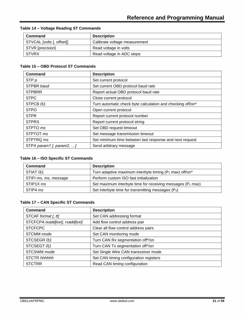
Table 14 – Voltage Reading ST Commands
Command Description
STVCAL [volts [, offset]] Calibrate voltage measurement
STVR [precision] Read voltage in volts
STVRX Read voltage in ADC steps
Table 15 – OBD Protocol ST Commands
Command Description
STP p Set current protocol
STPBR baud Set current OBD protocol baud rate
STPBRR Report actual OBD protocol baud rate
STPC Close current protocol
STPCB 0|1 Turn automatic check byte calculation and checking off/on*
STPO Open current protocol
STPR Report current protocol number
STPRS Report current protocol string
STPTO ms Set OBD request timeout
STPTOT ms Set message transmission timeout
STPTRQ ms Set minimum time between last response and next request
STPX param1 [, param2, …] Send arbitrary message
Table 16 – ISO Specific ST Commands
Command Description
STIAT 0|1 Turn adaptive maximum interbyte timing (P1 max) off/on*
STIFI ms, ms, message Perform custom ISO fast initialization
STIP1X ms Set maximum interbyte time for receiving messages (P1 max)
STIP4 ms Set interbyte time for transmitting messages (P4)
Table 17 – CAN Specific ST Commands
Command Description
STCAF format [, tt] Set CAN addressing format
STCFCPA txadd[ext], rxadd[ext] Add flow control address pair
STCFCPC Clear all flow control address pairs
STCMM mode Set CAN monitoring mode
STCSEGR 0|1 Turn CAN Rx segmentation off*/on
STCSEGT 0|1 Turn CAN Tx segmentation off*/on
STCSWM mode Set Single Wire CAN transceiver mode
STCTR hhhhhh Set CAN timing configuration registers
STCTRR Read CAN timing configuration
OBDLink Family
22 of 59 www.obdsol.com OBDLinkFRPMC
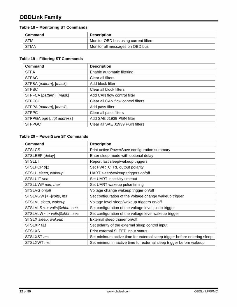
Table 18 – Monitoring ST Commands
Command Description
STM Monitor OBD bus using current filters
STMA Monitor all messages on OBD bus
Table 19 – Filtering ST Commands
Command Description
STFA Enable automatic filtering
STFAC Clear all filters
STFBA [pattern], [mask] Add block filter
STFBC Clear all block filters
STFFCA [pattern], [mask] Add CAN flow control filter
STFFCC Clear all CAN flow control filters
STFPA [pattern], [mask] Add pass filter
STFPC Clear all pass filters
STFPGA pgn [, tgt address] Add SAE J1939 PGN filter
STFPGC Clear all SAE J1939 PGN filters
Table 20 – PowerSave ST Commands
Command Description
STSLCS Print active PowerSave configuration summary
STSLEEP [delay] Enter sleep mode with optional delay
STSLLT Report last sleep/wakeup triggers
STSLPCP 0|1 Set PWR_CTRL output polarity
STSLU sleep, wakeup UART sleep/wakeup triggers on/off
STSLUIT sec Set UART inactivity timeout
STSLUWP min, max Set UART wakeup pulse timing
STSLVG on|off Voltage change wakeup trigger on/off
STSLVGW [+|-]volts, ms Set configuration of the voltage change wakeup trigger
STSLVL sleep, wakeup Voltage level sleep/wakeup triggers on/off
STSLVLS <|> volts|0xhhh, sec Set configuration of the voltage level sleep trigger
STSLVLW <|> volts|0xhhh, sec Set configuration of the voltage level wakeup trigger
STSLX sleep, wakeup External sleep trigger on/off
STSLXP 0|1 Set polarity of the external sleep control input
STSLXS Print external SLEEP input status
STSLXST ms Set minimum active time for external sleep trigger before entering sleep
STSLXWT ms Set minimum inactive time for external sleep trigger before wakeup

Reference and Programming Manual
OBDLinkFRPMC www.obdsol.com 23 of 59
Table 21 – Bluetooth Commands
Command Description
STBTCOD hhhhhh Set Bluetooth modem CoD
STBTDN ascii Set Bluetooth broadcasting device name
Table 22 – General Purpose I/O ST Commands
Command Description
STGPC pin1:options [, …, pinN:options] Configure I/O pins
STGPIR pin1 [, …, pinN] Read inputs
STGPIRH pin1 [, …, pinN] Read inputs, report value as hex
STGPOR pin1 [, …, pinN] Read output latches
STGPOW pin1:state [, …, pinN:state] Write output latches
Table 23 – Deprecated ST Commands
Command Description Replaced with
STCAFCP Add CAN flow control address pair STCFCPA
STCCFCP Clear all CAN flow control address pairs STCFCPC
STFAB Add block filter STFBA
STFAFC Add CAN flow control filter STFFCA
STFAP Add pass filter STFPA
STFAPG Add SAE J1939 PGN filter STFPGA
STFCA Clear all filters STFAC
STFCB Clear all block filters STFBC
STFCFC Clear all CAN flow control filters STFFCC
STFCP Clear all pass filters STFPC
STFCPG Clear all SAE J1939 PGN filters STFPGC
STIBR Set ISO baud rate STPBR
STIMCS Turn ISO manual checksum off/on STPCB
STPRBR Report actual OBD protocol baud rate STPBRR

OBDLink Family
24 of 59 www.obdsol.com OBDLinkFRPMC
8.2 General ST Commands
STCALSTAT Read the saved device voltage calibration status
(set by STVCAL). Will print one of four options: ANALOG IN: SAVED
Returned if STVCAL and STSAVCAL have both been run.
ANALOG IN: NO UD Returned if there is no user data available.
ANALOG IN: NOT READY Returned if STVCAL has not been run yet.
ANALOG IN: READY Returned if STVCAL has been run but STSVCAL has not.
STRSTNVM Reset all settings saved in the non-volatile memory
(NVM) to the factory defaults. This includes all programmable parameters, saved OBD protocol, UART baud rate, voltage calibration, ATI device ID string, AT@1 device description string, and all PowerSave configuration parameters. One-time
programmable values (AT@3, STSDI, STSAVCAL) and the user data byte (ATSD) will not be reset.
STSAVCAL Save all calibration values as factory defaults. The
values are saved in one-time programmable memory, therefore this operation can be performed only once. The following values are saved:
• Voltage calibration (set using ATCV or STVCAL)
• Voltage offset (set using STVOFS)
Returns ‘?’ if any of the calibration values have not been set, or if the STSAVCAL has already been used to successfully save the calibration values.
Note: This command is available only for stand-alone ICs.
STUIL 0|1 Disable or enable LEDs. This setting is written to
volatile memory, and will not survive a power cycle. Default is 1 (LEDs enabled).
8.3 UART Specific ST Commands
STBR baud Switch UART baud rate in software-friendly way.
The STBR command operates the same as the ATBRD command, with the following differences:
• Baud rate is specified as a decimal number in baud
• Returns ‘?’ if the specified baud rate cannot be generated with 3% or better accuracy
• The ID string returned is the STI string Examples:
STBR 300 switch baud rate to 300 bps STBR 115200 switch baud rate to 115.2 kbps STBR 2000000 switch baud rate to 2 Mbps
STBRT ms Set UART baud rate switch timeout for ATBRD and
STBR commands. The STBRT command sets the same timeout as the ATBRT command, except that the timeout is specified as a decimal value in milliseconds and the maximum timeout is 65535 ms (65.5 seconds).

Reference and Programming Manual
OBDLinkFRPMC www.obdsol.com 25 of 59
STSBR baud Switch UART baud rate in a terminal emulator-
friendly way. The STSBR command is designed to simplify UART baud rate switching when communicating with an OBDLink device “by hand”, using a terminal emulator program. The baud rate is specified as a decimal number in baud (38 to 10000000). Returns ‘?’ if the specified baud rate cannot be generated with 3% or better accuracy.
The command will print “OK” at the old baud rate, wait the time set by the STBRT or ATBRT command, then switch to the new baud rate. The command prompt will be printed at the new baud rate, but in most cases will not be visible in the terminal, since there will not be enough time to switch the terminal to the new baud rate.
The new baud rate will persist until the device is reset or power cycled. Use the command to save the new baud rate in non-volatile memory.
Use the following sequence to switch an STN1100 device to 921.6 kbps using a serial terminal:
1. Issue STSBR 921600 command
2. Look for “OK” response to make sure the baud rate is supported. The command prompt will be printed at the new baud rate, and will not be visible.
3. Switch the terminal to 921.6 kbps 4. Issue STI command to confirm successful
switch to the new baud rate. 5. Optionally, issue STWBR command to make the
new baud rate persist after device reset or power cycle.
STUFC 0|1 Set UART flow control mode. 0 will turn off flow
control, 1 will set flow control to use RTS/CTS. Default is 1.
This command is available for stand-alone STN ICs only, i.e. 1110, 1170, 2100, and 2120.
STWBR Write current UART baud rate to the non-volatile
memory (NVM). This command will save the current baud rate regardless of how the device was switched to this baud rate (ATBRD, STBR, or STSBR commands).
Host sends STBR
<baud_rate>
Can STN generate baud
rate with 3% accuracy?no
yes
Host: switch to
new baud rate
Print ‘?’
STN: wait for 75
msec, then print
the STI string
Host: received a valid STI
string?
Host: send
carriage return
Host: new baud rate not
supported, revert to old
baud rate
no
STN: received carriage
return?
STN: revert to old
baud rate
STN: print ‘OK’
and remain at new
baud rate
STN: print
command prompt
no
yes
Figure 1 - STBR Algorithm

OBDLink Family
26 of 59 www.obdsol.com OBDLinkFRPMC
8.4 Device ID ST Commands OBDLink supports a number of commands which
can be used to identify the device, get its unique serial number, and print the firmware and hardware versions.
STDI Print device hardware ID string, in this format:
<device_name> rX.Y X.Y is the device hardware revision number.
Example: OBDLink r1.7
STDICES Print the engine start count.
STDICPO Print the POR (Power on Reset) count. This count
will increment whenever the device is power cycled, and with firmware updates.
STDITPO Print the POR timer, which is the amount of time, in
seconds, the device has run since the last power cycle.
STI Prints firmware ID string, in this format:
STN<device_id> vX.Y.Z X.Y.Z is the firmware version number. Example: STN1101 v1.1.0
STIX Print the extended firmware ID string. Same as STI,
except this command also prints the firmware designator information (if it exists) and the firmware release date.
Example: STN1151 v4.5.0 [2019.04.12]
STMFR Print the device manufacturer ID string. If not
programmed at the factory for a specific OEM, on STN1110, STN1170, STN2100, and STN2120, this command returns “Generic”.
STSATI ascii Set ATI ID string. Accepts printable ASCII charac-
ters (0x20 to 0x7E). Maximum length is 31 characters. Leading and trailing spaces will be ignored.
STSDI ascii Set device hardware ID string. This command
allows one-time reprogramming of the device ID string, which is returned by the STDI command. The complete ID string must be supplied, including any hardware revision designations. Accepts printable ASCII characters (0x20 to 0x7E). Maximum length is 47 characters. Leading and trailing spaces will be ignored.
Example: STSDI OBD Gizmo r1.0 Note: This command is available only for stand-
alone ICs. The following table lists devices currently in
production, as well as devices still in development:
Device ID Device Name
STN1000 OBDLink CI
STN1100 OBDLink
STN1101 OBDLink S
STN1110 STN1110*
STN1120 microOBD 200
STN1130 OBDLink SX
STN1131 OBDLink JX
STN1150 OBDLink MX
STN1151 OBDLink MX BT
STN1152 OBDLink MX Wi-Fi
STN1155 OBDLink LX BT
STN1170 STN1170*
STN2100 STN2100*
STN2120 STN2120*
STN2230 OBDLink EX
STN2255 OBDLink MX+
*Default value. One-time user-programmable.

Reference and Programming Manual
OBDLinkFRPMC www.obdsol.com 27 of 59
STSN Print the device serial number. The serial number is
programmed at the factory and cannot be changed. Serial numbers for all devices are 12 digits long, and begin with the device ID, making each serial number unique across all OBDLink devices:
<device_id><serial_number>
Example: 110012345678
STS@1 ascii Set the device description string returned by AT@1
command. Accepts printable ASCII characters (0x20 to 0x7E). Maximum length is 47 characters. Leading and trailing spaces will be ignored.
8.5 Voltage ST Commands
STVCAL [volts [, offset]] Calibrate voltage measurement. The voltage
returned by ATRV and STVR commands can be calibrated using this command. Takes current voltage with a maximum value of 65.534, and a maximum precision of three decimal places . The optional offset parameter specifies voltage offset. Some devices have the ANALOG_IN input connected to the measured voltage with a constant voltage offset (e.g.: a series diode).
When no parameters are specified, the voltage calibration is set to factory defaults.
Example: STVCAL 12.345, 0.67
Note: The offset parameter is available only for
stand-alone ICs, and microOBD 200 (STN1120).
STVR [precision] Read voltage in volts. Returns calibrated voltage
measured by the ANALOG_IN pin. The optional precision parameter specifies precision in digits after decimal point (0 to 3). Default precision is two decimal points.
Example: 12.34
When the calibrated voltage exceeds 65.534V, digits are replaced by dashes.
Example: --.--
STVRX Read voltage in ADC steps. Returns the voltage on
ANALOG_IN pin in ADC counts. The range is 0x000 (AVSS) to 0xFFF (AVDD).
Example: 0x567
8.6 OBD Protocol ST Commands
STP p Set current protocol preset. This commands selects
the physical transceiver to be used for communication, and sets the attributes such as header size, baud rate, etc.
Note that this command does not actually open the communication channel. This can be done explicitly with the STPO command, or by sending an OBD request.
Baud rate can be changed using the STPBR command (currently not supported by J1850 protocols). Automatic checksum can be turned off using the STPCB command for all protocols except CAN.
SAE J1850
p Protocol
11 SAE J1850 PWM
12 SAE J1850 VPW
ISO 9141 and ISO 14230-4 (KWP2000)
p Protocol
21 ISO 9141 (no header, no autoinit)
22 ISO 9141-2 (5 baud autoinit)
23 ISO 14230-4 (no autoinit)
24 ISO 14230-4 (5 baud autoinit)
25 ISO 14230-4 (fast autoinit)
Note that presets without autoinit do not send automatic keep-alive messages.

OBDLink Family
28 of 59 www.obdsol.com OBDLinkFRPMC
OBDLink ICs support a maximum of three physical CAN channels: High Speed CAN, Medium Speed CAN, and Single Wire CAN. Internally, the OBDLink has only one CAN peripheral that can be mapped to different IC pins under software control. This means that only one CAN channel can be active at a time.
High Speed CAN (HS-CAN) is a dual-wire CAN transceiver connected to OBD port pins 6 and 14. Most newer (2008+) vehicles use it for legislated diagnostics. Older vehicles often use it for inter-ECU communication and enhanced manufacturer-specific diagnostics.
High Speed CAN
p Protocol
31 ISO 11898, 11-bit Tx, 500kbps, var DLC
32 ISO 11898, 29-bit Tx, 500kbps, var DLC
33 ISO 15765, 11-bit Tx, 500kbps, DLC=8
34 ISO 15765, 29-bit Tx, 500kbps, DLC=8
35 ISO 15765, 11-bit Tx, 250kbps, DLC=8
36 ISO 15765, 29-bit Tx, 250kbps, DLC=8
41 J1939 (11-bit Tx)
42 J1939 (29-bit Tx)
Medium Speed CAN (MS-CAN) is a dual-wire
transceiver typically connected to pins 3 and 11 of the OBD port (Ford MSC network).
Medium Speed CAN
p Protocol
51 ISO 11898, 11-bit Tx, 125kbps, var DLC
52 ISO 11898, 29-bit Tx, 125kbps, var DLC
53 ISO 15765, 11-bit Tx, 125kbps, DLC=8
54 ISO 15765, 29-bit Tx, 125kbps, DLC=8
Single Wire CAN (SW-CAN), also known as
“GMLAN”, is a single-wire transceiver connected to OBD port pin 1.
Single Wire CAN
p Protocol
61 ISO 11898, 11-bit Tx, 33.3kbps, var DLC
62 ISO 11898, 29-bit Tx, 33.3kbps, var DLC
63 ISO 15765, 11-bit Tx, 33.3kbps, DLC=8
64 ISO 15765, 29-bit Tx, 33.3kbps, DLC=8
SW-CAN has additional settings controlled by the
STCSWM command. Currently, for a given CAN preset, the protocol (ISO
11898, ISO 15765, J1939) and Tx ID size (11/29 bit) are hard-set. Baud rate and DLC can be changed using AT/ST commands. All CAN presets are configured to receive both 11-bit and 29-bit messages.
STPBR baud Set current OBD protocol baud rate. Takes bit rate
in bps as a decimal number. Currently, only the ISO and CAN protocols allow baud rate switching. The command will round the specified baud rate to the closest value that can be generated. When values outside the minimum/maximum possible baud rates are specified, they will be set to the corresponding minimum/maximum value. Use the STPBRR command to check the actual protocol baud rate.
STPBRR Report actual OBD protocol baud rate. Returns
current protocol bit rate in bps rounded to the nearest integer value. Returns ‘?’ if the protocol is AUTO. The actual baud rate will be reported whether the baud rate is variable or not.
STPC Close current protocol.
STPCB 0|1 Turn automatic check byte calculation and checking
off/on. When this setting is off, OBDLink will not automatically append checksum byte for transmitted messages, or verify checksum for received messages. This command does not apply to CAN protocols, where CRC is always on. Additionally, when checksum is off for ISO 14230 (KWP2000) protocols, minimum allowed OBD request length is increased to 2 bytes (one data byte and checksum). Default is 1.
STPO Open current protocol.
STPR Report current protocol number.
STPRS Report current protocol string.
STPTO ms Set OBD request timeout. Takes a decimal para-
meter in milliseconds (1 to 65535). Default is 102 ms. 0: timeout is infinite.

Reference and Programming Manual
OBDLinkFRPMC www.obdsol.com 29 of 59
STPTOT ms Set the message transmission timeout. This is the
time the device will wait for bus access, before printing “BUS BUSY”. Takes a decimal parameter in milliseconds (1 to 65535). The default values for each protocol are:
Protocol Default Timeout, ms
SAE J1850 PWM/VPW 300
ISO 9141-2/ISO 14230-4 300
ISO 15765-4 (CAN) 50
STPTRQ ms Set the minimum time between the last response
and the next request. Takes a decimal parameter in milliseconds (1 to 65535). For ISO 9141-2 and ISO 14230-4 protocols, this is the P3 timing.
The default for ISO 9141-2 and ISO 14230-4 is 56. For all others, it is 0.
STPX param1 [, param2, …] Transmit arbitrary message on OBD bus. Takes a
variable list of parameters, separated by commas. Each parameter is prefixed with a single-character parameter identifier, followed by parameter value, delimited by a colon character. This command will turn on segmentation, but will revert segmentation back to its previous state (on or off) after sending the message.
‘d’ (data) or ‘l’ (data length) are the only required parameters. If a parameter is omitted, default settings are used.
Param Description
h Header / CAN ID. If omitted, value, set by ATSH command is used.
d Data. If specified, [data length] parameter is not allowed.
l Data length. If specified, [data] parameter is not allowed. Instead, after the command is issued, user is prompted for data.
t Response timeout. If specified, overrides value, set by STPTO command. ATAT setting is still obeyed.
r Expected response count. Overrides ATR command setting.
x Extra data (protocol dependent): ISO 15765: extended address (over-
rides value, set by ATCEA command)
ISO 9141: expected response length in bytes
f Flags (binary-encoded hex) b0 – auto checksum flag enabled b16 – auto checksum (0: on, 1: off)
When ‘l’ (data length) parameter is specified, once
the command is issued, OBDLink sends DATA> prompt
over UART. At which time, user must send message data bytes as ASCII HEX characters. If there’s not enough memory for the data length specified, the command will return OUT OF MEMORY error, instead of the DATA> prompt. This mode is used to send
messages longer than the UART receive buffer will allow.
Examples: STPX h:686AF1, d:0100, t:50, r:1 STPX h:686AF1, l:2, t:50, r:1 DATA>0100 STPX d:0100 STPX h:123456, d:
8.7 ISO Specific ST Commands
STIAT 0|1 Turn ISO adaptive P1 max timing off/on. When this
mode is on, maximum interbyte time (P1 max) for ISO 9141 messages is adaptively reduced to allow communication with some ECUs that do not comply with the minimum intermessage time (P2 min) specified in ISO 9141-2 standard. Default is 1.
STIFI ms, ms, message Perform custom ISO fast initialization. The first
parameter is the initialization sequence LOW time (in
milliseconds), the second parameter is the HIGH time (in milliseconds), and the third parameter is a hex string for the init message. Default is 25, 25, C133F18166.
Note: Init message must include the header and checkbytes.
Example: STIFI 25, 25, C133F18166

OBDLink Family
30 of 59 www.obdsol.com OBDLinkFRPMC
STIP1X ms Set maximum interbyte time for receiving ISO
messages (P1 max). Takes a decimal parameter in milliseconds. Maximum is 65535 ms (65.5 seconds). Default is 20 ms.
STIP4 ms Set interbyte time for transmitting ISO messages
(P4). Takes a decimal parameter in milliseconds. Maximum is 65535 ms (65.5 seconds). Default is 5 ms.
8.8 CAN Specific ST Commands
STCAF format [, tt] Set CAN addressing format. The tt parameter
specifies target address extension and is required for formats 1 and 2. This command will use the default flow control “address” pairs, listed in Section 12.0, “ISO 15765 Message Reception”. Additional pairs may be added with the STCFCPA command.
The default addressing format for all CAN protocols is Normal.
Please see Section 13.0, “CAN Addressing Formats”.
Format Description
0 Normal
1 Extended with target address
2 Mixed with target address extension
Examples: STCAF 0 STCAF 1, F2
STCFCPA txadd[ext], rxadd[ext] Add a flow control CAN address pair. Takes two
three-digit or eight-digit parameters: txid is transmitter ID (i.e. ID transmitted by the OBDLink), and rxid is receiver ID (i.e. ID transmitted by the ECU).
Optionally takes two five-digit or ten-digit parameters
Examples: STCFCPA 7E0, 7E8 STCFCPA 18DA10F1, 18DAF110 STCFCPA 7E0 F2, 7E8 A2 STCFCPA 18DA10F1 F2, 18DAF110 A2
STCFCPC Clear all flow control address pairs.
STCMM mode Set CAN monitoring mode. This command affects
the operation of OBDLink in monitoring mode (STMA, STM, etc). The parameter specifies whether OBDLink should acknowledge received frames (this may be necessary, for example, if OBDLink is one of only two nodes on the bus), or remains silent. The default
setting is controlled by PP 21. The factory default is 0 (silent monitoring, no ACKs).
Mode can be one of the following:
Mode Description
0 Receive only – no CAN ACKs (default)
1 Normal node – with CAN ACKs
2 Receive all frames, including frames with errors – no CAN ACKs.
Note about STCMM 2: if an error occurs before the
DLC field is received, the OBDLink will re-print the previous frame.
STCSEGR 0|1 Disable or enable CAN segmentation for received
multi-frame messages. Automatically removes multi-frame PCI bytes and assembles the data into a single message. Default is 0 (CAN segmentation disabled).
STCSEGT 0|1 Disable or enable CAN segmentation for
transmitted multi-frame messages. Automatically splits the message into frames and adds multi-frame PCI bytes. Default is 0 (CAN segmentation disabled).
STCSWM mode Set Single Wire CAN transceiver mode. SW CAN
mode is set to Normal when a SW CAN protocol is opened and is automatically set to Sleep when the protocol is closed. When SW protocol is selected, transceiver mode can be switched to the specified mode. Mode parameter is a bit-encoded 3-bit number (0 to 8) that controls the three single-wire CAN transceiver control pins:
Bit 2 Bit 1 Bit 0
LOAD MODE1 MODE0
The following modes are commonly used:
Mode Description
0 Sleep
1 High Speed – High Speed Load Off
2 High Voltage Wakeup

Reference and Programming Manual
OBDLinkFRPMC www.obdsol.com 31 of 59
3 Normal (default)
5 High Speed – High Speed Load On
STCTR hhhhhh Set the CAN timing configuration registers. The
input is the 6-digit hex value that will be written to the
registers. This command can be used for custom timing on the CAN module.
STCTRR Print the CAN timing configuration registers (set by
STCTR).
8.9 Monitoring ST Commands
STM Monitor OBD bus using current filters.
STMA Monitor all messages on OBD bus. For CAN
protocols, all messages will be treated as ISO 15765. To monitor raw CAN messages, use the STM command.
8.10 Filtering ST Commands OBDLink devices feature a sophisticated filtering
system that can be precisely fine-tuned to isolate only the messages of interest, reducing the load on the host software and making it possible to use lower baud rates. For a detailed overview, see Section 11.0, “OBD Message Filtering”
A special note of caution: each of the “add filter” commands (STFBA, STFFCA, STFPA, and STFPGA) dynamically allocates a block of RAM to store the filter. Since the RAM is finite, it is possible to add too many filters. If not enough memory is available to add the filter, an “add filter” command will return the OUT OF MEMORY error. If this occurs, OBD requests may also start generating OUT OF MEMORY errors because the OBD message memory buffer is located in the same RAM.
The maximum number of filters that can be added depends on a number of factors, and may change slightly between firmware revisions even for the same scenario, as the memory allocation scheme is optimized and/or new functionality is added. To minimize the impact of these changes on your software, make sure that your code anticipates and gracefully handles OUT OF MEMORY errors.
STFA Enable automatic filtering.
STFAC Clear all filters.
STFBA [pattern], [mask] Add block filter. Same syntax as STFPA.
STFBC Clear all block filters.
STFFCA [pattern], [mask] Add flow control filter. Same syntax as STFPA.
STFFCC Clear all flow control filters.
STFPA [pattern], [mask] Add a pass filter. Takes two parameters: pattern
and mask. Pattern and mask can be any length from 0 to 5 bytes (0 to 10 ASCII characters), but both have to be the same length. The messages are matched MSB first, up to the filter length. Messages shorter than the filter length, will not match that filter.
If an odd number of ASCII characters is specified, a leading 0 will be added to the first byte. In other words,
STFPA 7E8,7FF ..is the same as STFPA 07E8,07FF
For 29-bit CAN, the first four bytes are CAN ID; for
11-bit CAN, the first two bytes are CAN ID. The first 3 bits for 29-bit CAN or the first 5 bits for
11-bit CAN should be don't care (0s in mask) and/or 0s in pattern.
STFPC Clear all pass filters.
STFPGA pgn [, tgt address] Add SAE J1939 PGN filter. PGN is specified as a
hexadecimal number 4 to 6 digits in length. If the specified PGN is shorter than 6 digits, leading 0s will be prepended. For PGNs that are longer than 4 hex characters, only the Data Page bit will be used in the extra byte; the Reserved and Priority bits are ignored.

OBDLink Family
32 of 59 www.obdsol.com OBDLinkFRPMC
A PGN filter is a complex pass filter that allows passing all messages that carry the specified PGN.
If the optional tgt address parameter is not specified, all messages containing the specified PGN will be included. If the target address is specified, only messages sent to that address will be included. Messages broadcast to all addresses will be included in both cases. To see only the broadcast messages, specify target address of 0xFF.
The following messages are included: If the specified PGN is of the PDU1 type, and target
address is not specified: all messages, containing the specified PGN in their header. This includes:
1. All messages, containing the specified PGN in the CAN header
2. Acknowledgment messages (PGN: 59392, $00E800), containing the specified PGN
3. Multi-segment BAM transfers a. TP.CM frames (PGN: 60416, $00EC00)
i. TP.CM_BAM messages b. TP.DT frames (PGN: 60160, $00EB00)
4. Multi-segment RTS/CTS transfers a. TP.CM frames (PGN: 60416, $00EC00)
i. TP.CM_RTS messages ii. TP.Conn_Abort messages
b. TP.DT frames (PGN: 60160, $00EB00) If the specified PGN is of the PDU1 type, and the
specified target address is 0xFF: all global broadcast messages (addressed to 0xFF), containing the specified PGN in their header. This includes:
1. Messages, containing the specified PGN in the CAN header
2. Acknowledgment messages (PGN: 59392, $00E800), containing the specified PGN
3. Multi-segment BAM transfers a. TP.CM frames (PGN: 60416, $00EC00)
i. TP.CM_BAM messages b. TP.DT frames (PGN: 60160, $00EB00)
If the specified PGN is of the PDU1 type, and the specified target address is other than 0xFF: all messages, containing the specified PGN in their header and addressed to the specified target address, plus all global broadcasts (addressed to 0xFF). This includes:
1. Messages, containing the specified PGN in the CAN header and addressed to the specified target address or 0xFF
2. Acknowledgment messages (PGN: 59392, $00E800), containing the specified PGN
3. Multi-segment BAM transfers a. TP.CM frames (PGN: 60416,
$00EC00) i. TP.CM_BAM messages
b. TP.DT frames (PGN: 60160, $00EB00)
4. Multi-segment RTS/CTS transfers a. TP.CM frames (PGN: 60416,
$00EC00) i. TP.CM_RTS messages ii. TP.Conn_Abort messages
b. TP.DT frames (PGN: 60160, $00EB00)
If the specified PGN is of the PDU2 type: all messages, containing the specified PGN in their header. This includes:
1. Messages, containing the specified PGN in the CAN header
2. Acknowledgment messages (PGN: 59392, $00E800), containing the specified PGN
3. Multi-segment BAM transfers a. TP.CM frames (PGN: 60416,
$00EC00) i. TP.CM_BAM messages
b. TP.DT frames (PGN: 60160, $00EB00)
4. Multi-segment RTS/CTS transfers a. TP.CM frames (PGN: 60416,
$00EC00) i. TP.CM_RTS messages ii. TP.Conn_Abort messages
b. TP.DT frames (PGN: 60160, $00EB00)
For multi-frame PGNs, OBDLink provides internal session management, including timeouts and sending of TP.CM_CTS, TP.CM_EndOfMsgACK, and TP.Conn_Abort messages, when not in monitoring mode. In monitoring mode, passive session management is used to follow TP.CM_BAM multi-segment messages and TP.CM_RTS multi-segment messages, requested by other nodes.
Only first-level encapsulated PGNs will be passed by this PGN filter. Specifically, PGNs returned via the Transfer messages (PGN: 51712, 0x00CA00) will not be filtered for. In order to filter for PGNs returned via the Transfer PGN, add a PGN filter for the 0x00CA00 PGN and then look for the enclosed PGN in the first three bytes of the Transfer PGN data.
This command is only available when an SAE J1939 protocol is selected.
Example: STFPGA 00FECB STFPGA FECB, F9
STFPGC Clear all SAE J1939 PGN filters.
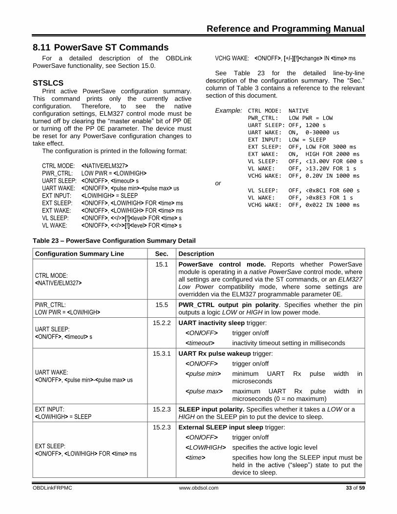
Reference and Programming Manual
OBDLinkFRPMC www.obdsol.com 33 of 59
8.11 PowerSave ST Commands For a detailed description of the OBDLink
PowerSave functionality, see Section 15.0.
STSLCS Print active PowerSave configuration summary.
This command prints only the currently active configuration. Therefore, to see the native configuration settings, ELM327 control mode must be turned off by clearing the “master enable” bit of PP 0E or turning off the PP 0E parameter. The device must be reset for any PowerSave configuration changes to take effect.
The configuration is printed in the following format: CTRL MODE: <NATIVE/ELM327> PWR_CTRL: LOW PWR = <LOW/HIGH> UART SLEEP: <ON/OFF>, <timeout> s UART WAKE: <ON/OFF>, <pulse min>-<pulse max> us EXT INPUT: <LOW/HIGH> = SLEEP EXT SLEEP: <ON/OFF>, <LOW/HIGH> FOR <time> ms EXT WAKE: <ON/OFF>, <LOW/HIGH> FOR <time> ms VL SLEEP: <ON/OFF>, <</>>[!]<level> FOR <time> s VL WAKE: <ON/OFF>, <</>>[!]<level> FOR <time> s
VCHG WAKE: <ON/OFF>, [+/-][!]<change> IN <time> ms See Table 23 for the detailed line-by-line
description of the configuration summary. The “Sec.” column of Table 3 contains a reference to the relevant section of this document.
Example: CTRL MODE: NATIVE PWR_CTRL: LOW PWR = LOW UART SLEEP: OFF, 1200 s UART WAKE: ON, 0-30000 us EXT INPUT: LOW = SLEEP EXT SLEEP: OFF, LOW FOR 3000 ms EXT WAKE: ON, HIGH FOR 2000 ms VL SLEEP: OFF, <13.00V FOR 600 s VL WAKE: OFF, >13.20V FOR 1 s VCHG WAKE: OFF, 0.20V IN 1000 ms or VL SLEEP: OFF, <0x8C1 FOR 600 s VL WAKE: OFF, >0x8E3 FOR 1 s VCHG WAKE: OFF, 0x022 IN 1000 ms
Table 23 – PowerSave Configuration Summary Detail
Configuration Summary Line Sec. Description
CTRL MODE: <NATIVE/ELM327>
15.1 PowerSave control mode. Reports whether PowerSave module is operating in a native PowerSave control mode, where all settings are configured via the ST commands, or an ELM327 Low Power compatibility mode, where some settings are overridden via the ELM327 programmable parameter 0E.
PWR_CTRL: LOW PWR = <LOW/HIGH>
15.5 PWR_CTRL output pin polarity. Specifies whether the pin outputs a logic LOW or HIGH in low power mode.
UART SLEEP: <ON/OFF>, <timeout> s
15.2.2 UART inactivity sleep trigger:
<ON/OFF> trigger on/off
<timeout> inactivity timeout setting in milliseconds
UART WAKE: <ON/OFF>, <pulse min>-<pulse max> us
15.3.1 UART Rx pulse wakeup trigger:
<ON/OFF> trigger on/off
<pulse min> minimum UART Rx pulse width in microseconds
<pulse max> maximum UART Rx pulse width in microseconds (0 = no maximum)
EXT INPUT: <LOW/HIGH> = SLEEP
15.2.3 SLEEP input polarity. Specifies whether it takes a LOW or a HIGH on the SLEEP pin to put the device to sleep.
EXT SLEEP: <ON/OFF>, <LOW/HIGH> FOR <time> ms
15.2.3 External SLEEP input sleep trigger:
<ON/OFF> trigger on/off
<LOW/HIGH> specifies the active logic level
<time> specifies how long the SLEEP input must be held in the active (“sleep”) state to put the device to sleep.

OBDLink Family
34 of 59 www.obdsol.com OBDLinkFRPMC
Configuration Summary Line Sec. Description
EXT WAKE: <ON/OFF>, <LOW/HIGH> FOR <time> ms
15.3.2 External SLEEP input wakeup trigger:
<ON/OFF> trigger on/off
<LOW/HIGH> specifies the active logic level
<time> specifies how long the SLEEP input must be held in the inactive (“wake”) state to wake the device from sleep.
VL SLEEP: <ON/OFF>, <</>>[!]<level> FOR <time> s
15.2.4 Voltage level sleep trigger:
<ON/OFF> trigger on/off
<</>> specifies whether the trigger region is below (<) or above (>) the <level> threshold setting
[!] this designator indicates that the trigger voltage setting is invalid, i.e. cannot be achieved with the current voltage calibration
<level> voltage threshold in volts ([d]d.ddV) or raw ADC steps (0xhhh)
<time> number of consecutive seconds the voltage must remain above or below the threshold value for the trigger to activate
VL WAKE: <ON/OFF>, <</>>[!]<level> FOR <time> s
15.3.3 Voltage level wakeup trigger. Same format as the voltage level sleep trigger.
VCHG WAKE: <ON/OFF>, [+/-][!]<change> IN <time> ms
15.3.4 Voltage change wakeup trigger:
<ON/OFF> trigger on/off
[+/-] specifies whether the trigger detects only rising voltage (+), only falling voltage (-), or a voltage change in any direction (no sign)
[!] this designator indicates that the voltage change setting is invalid, i.e. cannot be achieved with the current voltage calibration
<change> voltage change in volts ([d]d.ddV) or raw ADC steps (0xhhh)
<time> number of milliseconds between voltage samples
STSLEEP [delay] Enter sleep mode. Takes optional delay parameter
in seconds. When the delay is specified, the command prints “OK”, and returns to the command prompt. The sleep mode will be entered after the specified delay time. When the parameter is empty or 0 seconds delay is specified, the command will print “OK<CR>” and immediately put the device to sleep.
STSLLT Report last sleep/wakeup triggers, in this format:
SLEEP: <sleep trigger> WAKE: <wakeup trigger>
Sleep trigger can be one of the following:
Trigger Description
NONE Device did not enter sleep mode since last reset
CMD STSLEEP or ATLP command
UART UART inactivity timeout
EXT External sleep control input
VL Voltage level
Wakeup trigger can be one of the following:
Trigger Description
NONE Device did not wake up from sleep since last reset
UART UART Rx pulse
Reference and Programming Manual
OBDLinkFRPMC www.obdsol.com 35 of 59
EXT External sleep control input
VL Voltage level
VCHG Voltage change
Example: SLEEP: CMD WAKE: UART
STSLPCP 0|1 Set polarity of the PWR_CTRL output. 0: Normal power = HIGH, Low power mode = LOW 1: Normal power = LOW, Low power mode = HIGH The default setting is 0.
Note: This command is available only for stand-alone ICs.
STSLU sleep, wakeup UART sleep/wakeup triggers on/off. Each of the two
parameters can be independently configured as “on” or “off”. The first parameter specifies sleep trigger (UART inactivity timeout) setting, and the second one specifies wakeup trigger (low pulse on UART Rx input) setting. The defaults are sleep = off, wakeup = on.
Example: STSLU off, on
STSLUIT sec Set UART inactivity timeout. The parameter is
specified in seconds (decimal). The default is 1200 (20 minutes).
STSLUWP min, max Set UART wakeup pulse timing. The parameters
are specified in microseconds. The defaults are min = 0, max = 30000 (30 milliseconds).
STSLVG on|off Voltage change wakeup trigger on/off. The default
is off.
STSLVGW [+|-]volts, ms Configure voltage change wakeup trigger. The first
parameter specifies voltage difference between two samples. The optional ‘+’ or ‘-’ sign, preceding the voltage, specifies whether the trigger detects only rising voltage (+), only falling voltage (-), or a voltage change in any direction (no sign). The second parameter specifies the time between the samples in milliseconds. The value specified will be rounded to the nearest multiple of 250 ms, with any value below 250 being rounded up to the minimum setting of 250 ms. The default setting is 0.2, 1000 (voltage changing by 0.2V in any direction, with one second between the samples).
Example: STSLVGW +0.15, 750
STSLVL sleep, wakeup Turn voltage level sleep/wakeup triggers on/off.
Each of the two parameters can be specified as “on” or “off”. The first parameter specifies the sleep trigger setting, and the second parameter specifies the wakeup trigger setting. The defaults are sleep = off, wakeup = off.
STSLVLS <|> volts|0xhhh, sec Configure voltage level sleep trigger. The “<” or “>”
character specifies whether the trigger region is above or below the threshold voltage: “<” = below, “>” = above. The threshold voltage can be specified in volts with the maximum precision of two decimal places. It can also be specified in raw ADC steps by prefixing the value with ‘0x’. The sec parameter specifies how long the voltage must remain above or below the threshold before the device will enter sleep mode. The default is <13.00, 600 (below 13V for 600 seconds).
Examples: STSLVLS <12.85, 60 STSLVLS >0x8ab, 0
STSLVLW <|> volts|0xhhh, sec Configure voltage level wakeup trigger. The “<” or
“>” character specifies whether the trigger region is above or below the threshold voltage: “<” = below, “>” = above. The threshold voltage can be specified in volts with the maximum precision of two decimal places. It can also be specified in raw ADC steps by prefixing the value with ‘0x’. The sec parameter specifies how long the voltage must remain above or below the threshold before the device will wake up from sleep. The default is >13.20, 1 (above 13.2V for 1 second).
Examples: STSLVLW >13.15, 0
STSLVLW <0x8cd, 5
STSLX sleep, wakeup Enable or disable sleep/wakeup triggers associated
with the external sleep control input (SLEEP pin). Each of the two parameters can be specified as “on” or “off”. The defaults are sleep = off, wakeup = on.
STSLXP 0|1 Configure polarity of the SLEEP input.
0: LOW = sleep, HIGH = wake up 1: LOW = wake up, HIGH = sleep
The default setting is 0.

OBDLink Family
36 of 59 www.obdsol.com OBDLinkFRPMC
Note: This command is available only for stand-alone ICs, and microOBD 200 (STN1120).
STSLXS Print the status of the external SLEEP input.
Responds with “WAKE” or “SLEEP”.
STSLXST ms Specify how long the SLEEP input must be held in
the active (“sleep”) state to put the device to sleep. The
ms parameter is the minimum time in milliseconds. The default is 3000 (3 seconds).
STSLXWT ms Specify how long the SLEEP input must be held in
the inactive (“wake”) state to wake the device from sleep. The ms parameter is the minimum time in milliseconds. The default is 2000 (2 seconds).
8.12 Bluetooth Specific Commands
STBTCOD hhhhhh Set the Bluetooth modem CoD (Class of Device).
The input is the 6-digit hex CoD. The device needs to be power-cycled for this command to take effect. This is set in non-volatile memory, so it will survive a power-cycle. However, it will be reset during a factory reset, and may be changed during a firmware update.
STBTDN ascii Set the Bluetooth broadcasting device name.
Accepts printable ASCII characters (0x20 to 0x7E). Maximum length is 20 characters. Leading and trailing spaces will be ignored. The ‘%’ character can be used to select different options: To include an actual ‘%’ character in the device name, two “%%” must be used. To include the last n digits of the device serial number, “%ns” must be used. To include the last n digits of the Bluetooth address, “%nR” must be used. The parameter n is optional,
and will default to 5. If one ‘%’ is given, but is not followed by ‘%’, “nR”, “ns”, ‘R’, or ‘s’, the operation will fail and the device name will not be changed. This command requires a power cycle to take effect.
Examples: STBTDN OBDLink MX %3s If the serial number is 1234567890
the device name will be “OBDLink MX 890”.
STBTDN My Tool %4R%%%s If the serial number is 1234567890 and the Bluetooth address is 00043EABCDEF, the device name will be “My Tool CDEF%67890”.
Note: Commands in this section 8.12 “Bluetooth
Specific Commands” are only available for Bluetooth devices.
8.13 General Purpose I/O ST Commands
STGPC pin1:options [, …, pinN:options] Configure general purpose pins. Consult device
datasheet for open drain, pull-up, and pull-down feature availability of each general purpose pin.
pin: GPx pin number options: I input O output N0 disable open drain N1 enable open drain U0 disable internal pull-up U1 enable internal pull-up D0 disable internal pull-down D1 enable internal pull-down
Examples:
STGPC 0:O, 25:O, 3:I, 5:I
STGPC 1:O:N1, 2:I:U0
STGPIR pin1 [, …, pinN] Read general purpose inputs. Results are reported
as binary 1/0 values, separated by commas: Example: STGPIR 0, 4, 7, 63 Response: 1, 0, 0, 1
STGPIRH pin1 [, …, pinN] Read general purpose inputs, report values as LSB-
aligned hex value. Example: STGPIR 0, 4, 7, 63 Response: 09
STGPOR pin1 [, …, pinN] Read output latches. Results are reported as binary
1/0 values, separated by commas.

Reference and Programming Manual
OBDLinkFRPMC www.obdsol.com 37 of 59
Example: STGPOR 2, 4, 31 Response: 0, 1, 0
STGPOW pin1:state [, …, pinN:state] Write output latches.
Example: STGPOW 2:0, 4:1, 31:0
OBDLink Family
38 of 59 www.obdsol.com OBDLinkFRPMC
9.0 Error Messages This section documents the error and status
messages that you can receive from the OBDLink. ?
Invalid command. This error is displayed if the syntax of the command is not correct, or the command is not appropriate for the context (e.g., attempting to use the ATFI command with a protocol other than 5). ACT ALERT
The IC will switch to low power mode in 1 minute, unless it detects activity on UART. The timeout can be set using bit 4 of PP 0E to either 4 or 19 minutes.
Note: This message can only occur in the ELM327 PowerSave mode (see Section 15.1), and only if the PP 0E bit 3 is 1. BUFFER FULL
The IC ran out of memory to store incoming OBD messages. This error is not very common with the OBDLink, since it has a much larger buffer than the 256 byte buffer provided by the ELM327. If you are receiving BUFFER FULL messages, consider increasing UART baud rate (Section 8.2), turning off headers (ATH0) and spaces (ATS0), or use OBD message filters (Section 8.10). BUS BUSY
OBDLink tried to send an OBD command, but timed out before it could detect an idle bus state. In the majority of cases, this error indicates a wiring problem – one or more of the bus lines is stuck in an active state. BUS ERROR
The IC made an attempt to send an OBD message but the bus voltage did not change as expected. This is most likely due to a circuit problem (a short or an open) or the bus being shorted to battery voltage or ground. CAN ERROR
The CAN peripheral had trouble transmitting or receiving messages. Possible causes include:
• Device not connected to the CAN bus
• Wrong protocol/CAN baud rate
• Wiring problem DATA ERROR
Data formatting error: too few bytes received, incorrect header format, symbol timing, or framing error.
<DATA ERROR
This error message follows a response that failed an error detection byte check (CRC or checksum). It may be caused by any of the following:
• Bad electrical connection (e.g., oxidized diagnostic connector pins)
• Electromagnetic noise
• Cable that is too long, or poorly shielded
• Circuit problem
• CAN Auto Formatting (CAF) enabled for a protocol other than the ISO 15765-4
FB ERROR
Feedback error. OBDLink detected a mismatch between the commanded transmitter state (high or low), and the signal state seen at the receiver. Possible causes:
• Circuit problem
• J1850 bus lines or K-line stuck high or low
• Message collisions on K-line. This can happen when another scan tool is transmitting in parallel, or when the ATST timeout is too short, causing OBDLink to “step” on ECU replies to the previous request
LP ALERT
OBDLink is 2 seconds away from entering Low Power (standby) mode. The purpose of this message is to alert the host and allow it sufficient time to perform any housekeeping tasks (e.g., save data to nonvolatile memory before the power is cut). At this point, hardware reset is the only way to prevent the IC from entering the Low Power mode.
Note: This message can only occur in the ELM327 PowerSave mode (see Section 15.1), and only if the PP 0E bit 3 is 1. LV RESET
Low voltage reset (also known as “brown-out reset”). OBDLink has a built-in brown-out reset feature that resets the device when the supply voltage drops too low. After the voltage rises back above the trip point, the IC performs a full reset and prints “LV RESET”. NO DATA
There was no response from the vehicle before a timeout occurred. The request may not be supported, was blocked by the filters (see Section 11.0), or the timeout (ATST) is too short. OUT OF MEMORY
Not enough available RAM to complete the requested operation. <RX ERROR
CAN peripheral detected an error in the received message. Incorrect baud rate is the most likely cause.

Reference and Programming Manual
OBDLinkFRPMC www.obdsol.com 39 of 59
STOPPED A character received on UART interrupted the
execution of an OBD command. The current version of firmware ignores linefeed
characters (0x0A) to prevent this error from occurring inadvertently. UART RX OVERFLOW
UART Rx buffer overflow occurred. This error is most likely to happen under ISO 9141 and ISO 14230, when a large amount of UART data is sent to the OBDLink at a high baud rate, while the device is busy transmitting keep-alive messages.
UNABLE TO CONNECT OBDLink was unable to detect the OBD protocol.
Possible explanations include:
• Vehicle is not OBD-II compliant
• Ignition is off
• No power on diagnostic connector (e.g., blown fuse)
• Wiring problem
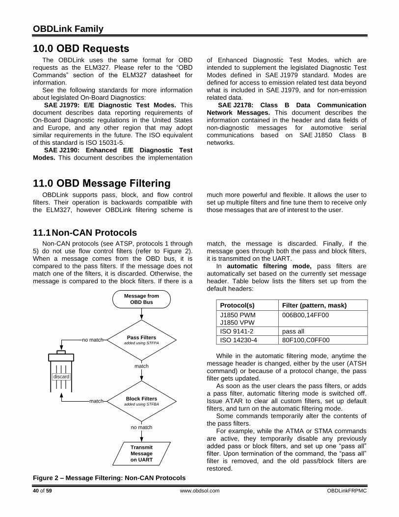
OBDLink Family
40 of 59 www.obdsol.com OBDLinkFRPMC
10.0 OBD RequestsThe OBDLink uses the same format for OBD
requests as the ELM327. Please refer to the “OBD Commands” section of the ELM327 datasheet for information.
See the following standards for more information about legislated On-Board Diagnostics:
SAE J1979: E/E Diagnostic Test Modes. This document describes data reporting requirements of On-Board Diagnostic regulations in the United States and Europe, and any other region that may adopt similar requirements in the future. The ISO equivalent of this standard is ISO 15031-5.
SAE J2190: Enhanced E/E Diagnostic Test Modes. This document describes the implementation
of Enhanced Diagnostic Test Modes, which are intended to supplement the legislated Diagnostic Test Modes defined in SAE J1979 standard. Modes are defined for access to emission related test data beyond what is included in SAE J1979, and for non-emission related data.
SAE J2178: Class B Data Communication Network Messages. This document describes the information contained in the header and data fields of non-diagnostic messages for automotive serial communications based on SAE J1850 Class B networks.
11.0 OBD Message Filtering OBDLink supports pass, block, and flow control
filters. Their operation is backwards compatible with the ELM327, however OBDLink filtering scheme is
much more powerful and flexible. It allows the user to set up multiple filters and fine tune them to receive only those messages that are of interest to the user.
11.1 Non-CAN Protocols Non-CAN protocols (see ATSP, protocols 1 through
5) do not use flow control filters (refer to Figure 2). When a message comes from the OBD bus, it is compared to the pass filters. If the message does not match one of the filters, it is discarded. Otherwise, the message is compared to the block filters. If there is a
match, the message is discarded. Finally, if the message goes through both the pass and block filters, it is transmitted on the UART.
In automatic filtering mode, pass filters are automatically set based on the currently set message header. Table below lists the filters set up from the default headers:
Protocol(s) Filter (pattern, mask)
J1850 PWM J1850 VPW
006B00,14FF00
ISO 9141-2 pass all
ISO 14230-4 80F100,C0FF00
While in the automatic filtering mode, anytime the
message header is changed, either by the user (ATSH command) or because of a protocol change, the pass filter gets updated.
As soon as the user clears the pass filters, or adds a pass filter, automatic filtering mode is switched off. Issue ATAR to clear all custom filters, set up default filters, and turn on the automatic filtering mode.
Some commands temporarily alter the contents of the pass filters.
For example, while the ATMA or STMA commands are active, they temporarily disable any previously added pass or block filters, and set up one “pass all” filter. Upon termination of the command, the “pass all” filter is removed, and the old pass/block filters are restored.
Figure 2 – Message Filtering: Non-CAN Protocols
Message from
OBD Bus
Pass Filtersadded using STFPA
Block Filtersadded using STFBA
Transmit
Message
on UART
no match
no match
match
match
discard

Reference and Programming Manual
OBDLinkFRPMC www.obdsol.com 41 of 59
ATMR and ATMT commands behave the same way, except that instead of setting a “pass all” filter, they set up a filter to accept messages based on the address of the receive (or transmit) node passed as the parameter.
STM command uses all filters “as-set”: it does not modify them in any way.
ATSR turns off the automatic filtering mode, and sets up a pass filter to accept messages sent to the
receive address provided as the parameter to ATSR. In order to directly manipulate the filters, use the
filtering ST commands described in Section 8.10 “ Filtering ST Commands”.
11.2 CAN Protocols This section describes how message filtering works
Figure 3 – Message Filtering: CAN Protocols
CAN Frame from
Network
Flow Control Filters added using STFFCA
Pass Filtersadded using STFPA
Block Filtersadded using STFBA
Transmit
CAN Frame
on UART
CAN HW Filterset via ATCF/ATCM
no match
match
match
no match
no match
no match
match
match
Protocol = ISO 11898?
yes
no
ISO 11898 Frame
CAN Protocol?ISO 15765
ISO 15765 Frame SAE J1939 Frame
SAE J1939
discard

OBDLink Family
42 of 59 www.obdsol.com OBDLinkFRPMC
with CAN protocols (see ATSP, protocols 6 through C). When a CAN frame comes in from the network, it
must first go through the CAN hardware filter. If there is no match, the frame is discarded.
If the protocol is set to ISO 11898, all incoming frames are treated as ISO 11898 frames, and are sent straight through to the pass filters.
If the protocol is either ISO 15765 or J1939, the frame is compared against the flow control filters to determine whether it is an ISO 15765/J1939 or an ISO 11898 (“raw”) CAN frame.
ISO 11898 frames are compared to the pass filters. If there is no match, the frame is discarded. Otherwise, the frame is compared to the block filters, and if there is no match, it is transmitted on the UART.
ISO 15765/J1939 frames bypass the pass filters. As long as the comparison with the block filters results in a “no match”, the frame is transmitted on the UART.
Under the ISO 15765 protocol, in automatic filtering mode, flow control filters are automatically set based on the currently set message header. Table below lists the filters set up from the default CAN headers:
CAN ID Type Filter (pattern, mask)
11-bit 7E8,7F8
29-bit 18DAF100,1FFFFF00
While in the automatic filtering mode, anytime the
user changes the headers using the ATSH command,
or by switching from 11-bit to 29-bit CAN IDs, the flow control filter gets updated.
Automatic filtering mode is switched off when the user clears the flow control filters, adds a flow control filter, or sets the CAN hardware filter. To clear all custom filters, and set up default filters, issue the ATAR command.
The ATMA command sets the flow control, pass, and block filters for “pass all, block none” operation. When the command terminates, the old filters are restored.
The STMA command works the same way as ATMA, except that it also sets the CAN hardware filter for “pass all” operation. Upon termination, the old CAN hardware filter is restored.
ATMR and ATMT commands behave the same way, except that instead of setting a “pass all” filter, they set up a filter to accept messages based on the address of the receive (or transmit) node passed as the parameter.
STM command uses the filters “as-set”: it does not modify them in any way.
ATSR turns off the automatic filtering mode, and sets up a pass filter to accept messages sent to the receive address provided as the parameter to ATSR.
In order to directly manipulate the filters, use the filtering ST commands described in Section 8.10 “ Filtering ST Commands”.

Reference and Programming Manual
OBDLinkFRPMC www.obdsol.com 43 of 59
12.0 ISO 15765 Message Reception For most users, CAN message reception works “out
of the box”, as configured by default. However, for those users who wish to take full advantage of the OBDLink’s CAN architecture, it is important to understand what goes on behind the scenes.
You will notice that the flowchart in Figure 4 is simply a more detailed version of the flowchart from Section 11.2. Therefore, in this section we will omit the left half of the flowchart, and describe what happens
when the incoming CAN frame is identified as an ISO 15765 CAN frame.
If the RTR bit is set, the frame is determined to be a remote frame. As long as it is not discarded by the block filters, it gets sent over UART.
If the frame is not a remote frame, additional processing takes place. The protocol control information (PCI) byte is processed to determine whether it is a valid ISO 15765-2 frame, and what type
Figure 4 – ISO 15765 Message Reception
CAN Frame from
Network
Flow Control Filters added using STFFCA
Process PCI
Pass Filtersadded using STFPA
Flow Control On?set via ATCFC
ID Type
Look for Rx ID in
11-bit FC ID Pairsadded using STCFCPA
Transmit
Flow Control
Frame
Block Filtersadded using STFBA
Transmit
CAN Frame
on UART
CAN HW Filterset via ATCF/ATCM
no match
match
match
ISO15765 Frame
Remote
Frame?
no
yes
Valid
ISO15765-2
First Frame?
yes
no
yes
no
11 bit
29 bit
no match
no match
no match
not found
match
match
found
ISO11898 Frame
discard

OBDLink Family
44 of 59 www.obdsol.com OBDLinkFRPMC
of frame it is (single, first, consecutive, or flow control). If the frame is not a valid ISO 15765-2 first frame, or
if flow control is off, it is passed to the block filters. If the frame is a valid ISO 15765-2 first frame, and
flow control is on, what happens next is determined by the ID type.
A 29-bit frame ID contains the address of the transmitter, therefore a flow control frame is transmit-ted for every ISO 15765-2 first frame, before the frame is passed to the block filters.
An 11-bit frame is first compared to any flow control 11-bit address pairs. If no address pairs have been added (via the STCFCPA command), then the flow control frame will be transmitted with TxID = RxID - 8 (e.g. for the first frame with ID 7E8, flow control frame
will be transmitted on ID 7E0). If any address pairs have been added, then the Rx ID will be compared to the FC address pairs, and if a match is found, a flow control frame will be transmitted on the corresponding Tx ID; if a match is not found, no flow control frame will be sent. Note that when adding custom flow control filters for 11-bit CAN messages using the STFFCA command, it is important to add corresponding flow control 11-bit address pair (using STCFCPA) if the user wants to have the flow control frames be sent to IDs other than RxID - 8.

Reference and Programming Manual
OBDLinkFRPMC www.obdsol.com 45 of 59
13.0 CAN Addressing Formats
OBDLink supports all 4 CAN addressing formats. There is limited support for backwards compatibility with the ELM327, however OBDLink addressing scheme is much more powerful and flexible. It allows
the user to set the desired format and filter CAN traffic as desired.
See also ISO 15765-2 Section 7.3 Mapping of the N_PDU fields.
13.1 Normal With normal addressing format, a unique CAN
identifier encapsulates the source address and the target address. There are no specific fields in this identifier. This addressing format will use the default flow control “address” pairs, listed in section 12.0, “ISO 15765 Message Reception”. Additional pairs may be added with the STCFCPA command.
This is the default addressing format for 11-bit CAN protocols.
To use this addressing format, use the following
setup sequence. 1. Set addressing format to normal 2. If using multi-frame messaging
a. 11-bit: use flow control offset b. 29-bit: must add flow control pairs
3. Setup receive filters when not using default flow control pairs
Example: STP 33 STCAF 0 STCFCPA 7E0, 7E8 STCAF 0 STCFCPA 18DA10F1, 18DAF110
13.2 Normal fixed Normal fixed addressing is a sub-format of normal
addressing where the mapping of the address information into the CAN identifier is further defined. When using normal fixed addressing, only 29-bit CAN identifiers are allowed. This format will use the default flow control pair scheme, listed in section 12.0, “ISO 15765 Message Reception”. Additional pairs may be added with the STCFCPA command.
This is the default addressing format for 29-bit CAN protocols, with no pairs defined.
To use this addressing format, use the following setup sequence.
1. Set protocol to ISO 15765, 29-bit 2. Set addressing format to normal 3. Clear call CAN flow control filters
Example: STP 34 STCAF 0 STFFCC
13.3 Extended Extending addressing takes one byte from the
data field and uses it as an address field.
Example: STCAF 1, F2 STFA ATTA
13.4 Mixed
Examples: STCAF 2, F2
OBDLink Family
46 of 59 www.obdsol.com OBDLinkFRPMC
14.0 SAE J1939 The SAE J1939 protocol is a subset of CAN
designed for heavy-duty vehicles such as trucks, buses, and earth-moving equipment.
The flowchart (Figure 5) describes OBDLink’s implementation of the J1939 message reception algorithm. The left half of the flowchart is described in detail in Section 11.2. This section describes what happens after the incoming CAN frame has been identified as a J1939 frame.
If at least one PGN filter is defined, and the message has a 29-bit header, it is processed based on its type:
• ACK (Acknowledgement)
• TP.CM (Connection Management)
• TP.DT (Data Transfer) The algorithms used to process the frames, are
shown in subsequent flowcharts. To request a PGN, enter it as a 3-byte value: >00FEEE The response may look something like this: 6 0FEEE 00 FA 78 B0 B6 FF FF FF FF By default, the OBDLink will convert the 3-byte
request to little-endian format, before transmitting it on the J1939 bus. Use ATJ S to disable this behavior, and ATJ E to turn it back on. If automatic filtering is enabled
(i.e., no custom filters are defined), the OBDLink will add a temporary filter, which will be deleted after the message reception is completed.
The OBDLink is capable of monitoring multiple PGNs at the same time. To use this feature, use the STFPGA command to add the filters, and STM to monitor. These filters also work with multi-frame J1939 messages.
When the STFPGA command is called with the target address parameter omitted or set to FF, the filter will pass PDU1 messages containing the PGN and addressed to FF, as well as all PDU2 messages containing the PGN.
When the target address is specified, and is other than FF, the PGN filter will pass messages that contain the specified PGN and are addressed to the target address, in addition to the broadcasted messages.
The following example shows the commands necessary to set up the OBDLink to receive EEC1 (PGN 61444) and DM1 messages (PGN 65226):
ATZ STP 42 STCMM 1 ATH 1 STFAC STFPGA F004 STFPGA FECA STM
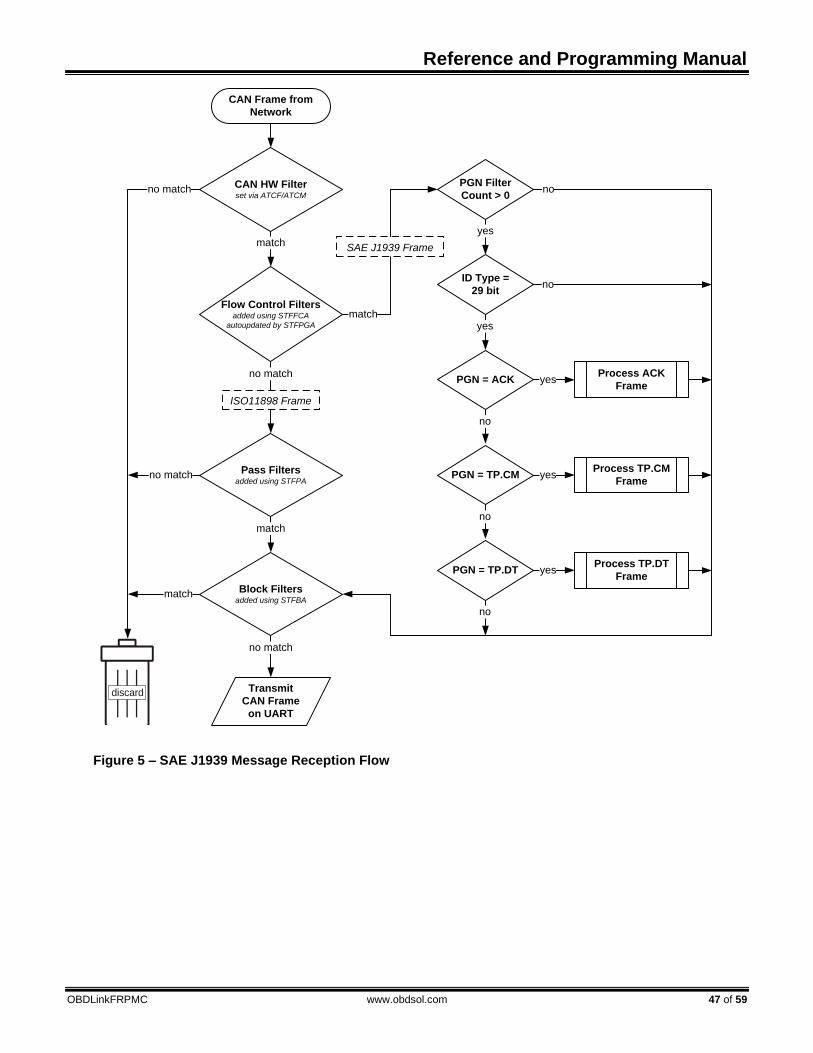
Reference and Programming Manual
OBDLinkFRPMC www.obdsol.com 47 of 59
CAN Frame from
Network
Flow Control Filters added using STFFCA
autoupdated by STFPGA
Pass Filtersadded using STFPA
Block Filtersadded using STFBA
Transmit
CAN Frame
on UART
CAN HW Filterset via ATCF/ATCM
no match
match
match
SAE J1939 Frame
PGN Filter
Count > 0
yes
no
no match
no match
no match
match
match
ISO11898 Frame
discard
PGN = ACK
no
yes
ID Type =
29 bit
yes
no
PGN = TP.CM
no
yes
PGN = TP.DT
no
yes
Process ACK
Frame
Process TP.CM
Frame
Process TP.DT
Frame
Figure 5 – SAE J1939 Message Reception Flow

OBDLink Family
48 of 59 www.obdsol.com OBDLinkFRPMC
PGN Filtersadded using STFPGA
no match
match
discard
Begin
End
Frame is TP.CM_RTS
no
Begin
End
Frame is TP.CM_BAM
no
yesCreate/update
BAM TP session
Frame is
TP.Conn_Abort
no
yes
Remove the
corresponding
TP session
yes
Create/update
RTS/CTS
TP session
Flow Control On?set via ATCFC
yes
no
Send TP.CM_CTS
Frame
PGN Filtersadded using STFPGA
no match
match
discard
Figure 6 - Process ACK Frame
Figure 7 - ProcessTP.CM Frame
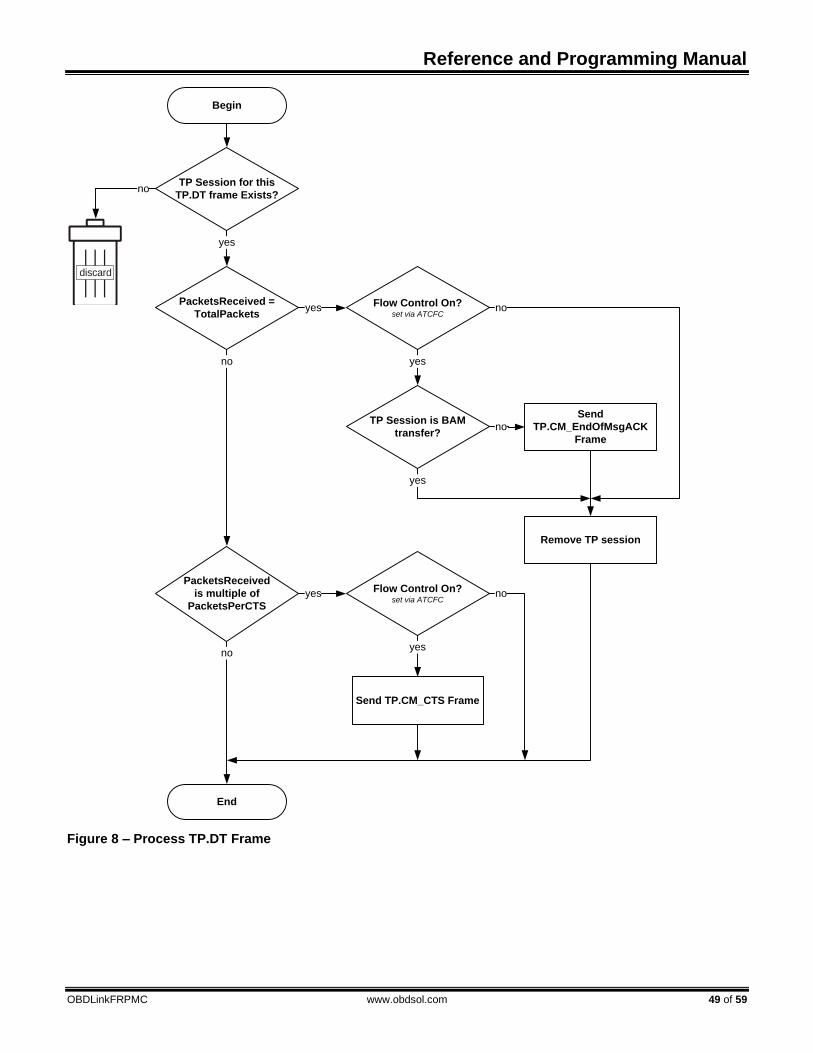
Reference and Programming Manual
OBDLinkFRPMC www.obdsol.com 49 of 59
Figure 8 – Process TP.DT Frame
TP Session for this
TP.DT frame Exists?no
yes
discard
Begin
End
PacketsReceived =
TotalPackets
no
yes
Send
TP.CM_EndOfMsgACK
Frame
PacketsReceived
is multiple of
PacketsPerCTS
no
yes
Send TP.CM_CTS Frame
Flow Control On?set via ATCFC
yes
no
TP Session is BAM
transfer?no
Remove TP session
yes
Flow Control On?set via ATCFC
yes
no

OBDLink Family
50 of 59 www.obdsol.com OBDLinkFRPMC
15.0 PowerSave Functionality The OBDLink features a sophisticated power
management system (PowerSave™) that can be used to put the device in low power mode. The primary purpose of PowerSave is to prevent the vehicle’s battery from being drained when the device is left plugged in for extended periods of time (e.g., permanent in-vehicle installations).
The concept of a trigger is key to understanding the operation of PowerSave. A trigger is an event or a condition that causes the device to either go to sleep, or wake up from sleep. “Go to sleep after 5 minutes of UART inactivity” and “wake up when vehicle system voltage goes above 12.8 volts” are examples of triggers. Each trigger can be independently enabled or disabled.
The following sections describe the PowerSave functionality, while Section 8.11 describes the commands and parameters used to configure and control the power management system. You can use the STSLCS command to print a summary of the active PowerSave configuration settings.
15.1 Control Modes There are two control modes for the PowerSave
functionality: native and ELM327. Use bit 7 (“master enable”) of the programmable parameter 0E (PP 0E) to switch between the modes. See the description of the ATPP command for more information about PP 0E.
By default, OBDLink is operating in the native PowerSave control mode.
15.1.1 Native PowerSave Mode
When the “master enable” bit of PP 0E is cleared, or PP 0E is off, OBDLink is in the native PowerSave control mode.
In this mode, the rest of the 0E programmable parameter bits are ignored and the PowerSave is controlled exclusively via ST Sleep commands. In native mode, the ATLP command is unavailable. Also, the ELM327 “ACT ALERT” and “LP ALERT” messages are not displayed.
15.1.2 ELM327 Low Power Mode
Note: this mode had been implemented for compatibility with software written for the ELM327. The native PowerSave mode has a number of important advantages over the ELM327 Low Power mode, including greater flexibility, more straightforward configuration, and default settings that had been optimized for more reliable performance.
When the “master enable” bit of the 0E programmable parameter is set and PP 0E is on, OBDLink is in the ELM327 control mode.
In this mode, most PowerSave settings are overridden by the PP 0E. However, the following settings that do not have a PP 0E equivalent can still be adjusted via their corresponding ST Sleep commands:
• UART wakeup pulse timing (STSLUWP)
• External SLEEP input polarity (STSLXP)
• Voltage based triggers (STSLVL, STSLVLS, STSLVLW, STSLVG, STSLVGW)
By default, instead of the fixed ELM327 minimum
UART Rx wakeup pulse requirement of 128 μs, OBDLink pulse width is set to 0 (20 ns). This is done to allow the user to wake up the device by sending characters, even at the highest supported UART baud rate.
In the ELM327 PowerSave control mode, STSLCS command will report the actual active configuration that is set via the 0E programmable parameter.
OBDLink external SLEEP input functions as the ELM327 IgnMon input.
15.2 Sleep Triggers Device can be put to sleep using one of the four
sleep triggers:
• Sleep commands (STSLEEP and ATLP)
• UART inactivity (STSLU)
• External SLEEP input (STSLX)
• Voltage level (STSLVL) Multiple sleep triggers can be enabled at the same
time. The first trigger that gets activated will put the device to sleep.
By default, all sleep triggers are off. Warning: before you enable a sleep trigger or issue
the STSLEEP command, make sure that the wakeup triggers are enabled and properly configured. The only other means of bringing the device out of the sleep state is to initiate a hardware reset, either via the
RESET¯¯¯¯¯ input, or by cycling the power.
15.2.1 STSLEEP and ATLP Commands
The device will go to sleep when it receives the ATLP or STSLEEP command. The ATLP command is available only in the ELM327 Low Power Mode.

Reference and Programming Manual
OBDLinkFRPMC www.obdsol.com 51 of 59
The STSLEEP command has an optional delay parameter. The purpose of the delay is to prevent the device from going to sleep prematurely: some hosts randomly toggle the UART communication lines and can unintentionally wake up the device as they are shutting down or entering the standby mode.
15.2.2 UART Inactivity
The OBDLink can be configured to go to sleep automatically after a period of UART inactivity.
UART inactivity sleep trigger is turned on/off using the STSLU command (it is off by default). Use the STSLUIT command to set the UART inactivity sleep timeout.
Warning: OBDLink UART inactivity sleep trigger is
disabled while any command is executing. In other words, OBDLink must print the command prompt before it will act on a sleep trigger. Therefore, commands which require UART activity to terminate their execution (e.g., ATMA, STMT, etc) will keep the device awake indefinitely. A continuous stream of incoming messages may also prevent the device from going to sleep. This may occur, for example, if message filters are set up to accept bus traffic intended for other nodes.
15.2.3 External SLEEP Input
Another automatic sleep trigger is the external SLEEP input. This trigger is off by default. When enabled (using the STSLX command), it allows the external circuitry to control the sleep state.
When OBDLink senses a logic low on the SLEEP pin, it immediately aborts any OBD reception in progress, or monitoring command that is active at the time, and prints the command prompt. It then monitors the SLEEP input and enters the PowerSave mode if the minimum low time (specified by the STSLXST command) is satisfied.
Note: Stand-alone ICs, and microOBD 200
(STN1120) allow the polarity of the external SLEEP input to be inverted, via the STSLXP command.
The following are some of the possible uses of this
trigger:
• “Host present” detect – sleep/wakeup when the host disconnects/connects or starts up/shuts down (goes into standby)
• Ignition key detect – sleep/wakeup depending on the ignition key position
• Direct sleep control via host microcontroller
The logic state of the SLEEP input state can be polled using the STSLXS and ATIGN commands.
See Section 15.6 for device-specific implementation details.
15.2.4 Voltage Level Sleep
The OBDLink can also enter sleep mode based on the voltage on the ANALOG_IN input. This trigger can be configured in the variety of ways. The settings specify voltage threshold, whether the trigger is active above or below the threshold setting, and the amount of time the voltage must stay below or above the threshold for the device to enter sleep mode.
The voltage level sleep trigger can be used to put the device into the low power mode when the engine shuts down and the alternator stops generating power. The delay is designed to prevent the device from entering sleep when the system voltage dips below the specified threshold due to momentary load changes. The default settings should work for most vehicles with 12-volt lead-acid batteries.
Use the STSLCS command to verify that the trigger was properly configured. An exclamation point (‘!’) in front of the voltage setting means that the trigger setting is invalid, and the trigger will never activate. Refer to Section 15.4 “Voltage Trigger Considerations” for more information.
Note: In order for the voltage level sleep trigger to
operate properly on the stand-alone ICs, or the microOBD 200 module (STN1120), the voltage measurement must be calibrated using the ATCV or STVCAL commands. The calibration is not necessary for the OBDLink scan tools, since it is done at the factory.
15.3 Wakeup Triggers There are four wakeup triggers:
• UART Rx pulse (STSLU)
• External SLEEP input (STSLX)
• Voltage level (STSLVL)
• Voltage change (STSLVG)
After any wakeup trigger timing requirements are satisfied, the OBDLink will wake up and perform an ATWS reset. The wakeup takes several milliseconds, therefore the host must wait for the command prompt before issuing any commands.
The STSLLT command can be used to determine which trigger caused the device to wake up.
By default, UART Rx pulse and external SLEEP input wakeup triggers are on, and voltage triggers are off.
OBDLink Family
52 of 59 www.obdsol.com OBDLinkFRPMC
15.3.1 UART Rx Pulse Wakeup
OBDLink can be configured to wake up on an active pulse detected on the UART Rx input. The host can generate the pulse by holding the Rx line in a logic low state, transmitting an RS232 “break” signal, or sending a character on UART whose bit pattern produces a pulse of the required duration.
The wakeup pulse has minimum and maximum timing requirements, which are set using the STSLUWP command, and are accurate to within approximately 5 μs. By default, the minimum wakeup pulse width is set to 0, which translates to an absolute minimum pulse width requirement of 20 ns. It can be increased to improve noise rejection; however, increasing the minimum pulse width will limit the maximum baud rate that the host must use to transmit the wake-up character. Due to the implementation limitations, setting the minimum wakeup pulse width to any value below 15 μs will cause it to be rounded down to 0 (20 ns).
The purpose of the maximum wakeup pulse width requirement is to avoid unintentional wakeups. Some PC hosts (especially ones using the RS232 connection) cause the UART Rx line to go low or generate a slow (200 ms or longer) pulse as the host is shutting down or entering standby. The default setting is 30 ms, which allows the device to wake up on a character transmitted over UART at baud rates as low as 300 baud. To disable the maximum pulse requirement and have OBDLink wake up on the high to low UART Rx transition (instead of a pulse), set the maximum pulse timing setting to 0.
15.3.2 External SLEEP Input Wakeup
OBDLink can be configured to wake up when it senses logic high on the external SLEEP control input.
The STXWT commands sets the minimum time the SLEEP input must remain high in order to bring the device out of the sleep state. The setting of 0 will result in a minimum time requirement of 15 μs.
Note: Stand-alone ICs and microOBD 200
(STN1120) allow the polarity of the external SLEEP input to be inverted, via the STSLXP command.
Section 15.2.3 lists possible applications for the
external SLEEP input.
15.3.3 Voltage Level Wakeup
The OBDLink can also wake up based on the voltage on the ANALOG_IN input. This trigger can be configured in a variety of ways. The settings specify voltage threshold, whether the trigger is active above or below the threshold setting, and the minimum
amount of time the voltage must stay below or above the threshold for the device to wake up.
The voltage level wakeup trigger can be used to wake up the device when the engine starts up and the alternator causes the system voltage to increase. The default settings should work for most vehicles with lead-acid batteries.
Use the STSLCS command to verify that the trigger was properly configured. An exclamation point (‘!’) in front of the voltage setting means that the trigger setting is invalid, and the trigger will never activate. Refer to Section 15.4 “Voltage Trigger Considerations” for more information.
Note: In order for the voltage level wakeup trigger
to operate properly on stand-alone ICs or microOBD 200 module (STN1120), the voltage measurement must be calibrated using the ATCV or STVCAL commands. The calibration is not necessary for the OBDLink scan tools, since it is done at the factory.
15.3.4 Voltage Change Wakeup
The OBDLink can be configured to wake up when the difference between two consecutive voltage samples taken at the ANALOG_IN input exceeds a predefined threshold. The settings specify polarity of the change (rising, falling, or either), the change in volts or ADC steps, and the time between the samples.
The voltage level wakeup trigger can be used to wake up the device when the starter motor is cranking the engine (battery voltage dips) or when the engine starts up (voltage rises due to alternator running). This wakeup trigger can be more reliable than the voltage level wakeup trigger, since it does not rely on a specific voltage level which can vary between vehicles, but instead detects voltage change, which happens every time engine starts no matter what the battery level or the alternator voltage is.
Use the STSLCS command to verify that the trigger was properly configured. An exclamation point (‘!’) in front of the voltage setting means that the trigger setting is invalid, and the trigger will never activate. Refer to Section 15.4 “Voltage Trigger Considerations” for more information.
Note: If a non-default voltage scaling is used for the
stand-alone ICs or the microOBD 200 module (STN1120), the voltage measurement must be calibrated using the ATCV or STVCAL commands, for the voltage change wakeup trigger to operate properly.
15.4 Voltage Trigger Considerations Analog voltage that OBDLink “sees” on the
ANALOG_IN pin is represented internally by a 12-bit

Reference and Programming Manual
OBDLinkFRPMC www.obdsol.com 53 of 59
integer. The conversion is done by an internal Analog to Digital Converter (ADC for short). The voltage represented by a single bit is called an “ADC step”, and is measured in volts per bit (V/bit).
Since the maximum voltage that can be directly measured by the ANALOG_IN pin is very low (about 3V), the pin is normally connected to the voltage source to be measured via an external voltage divider. As its name implies, the voltage divider outputs a voltage that is a fraction of the actual input voltage. For example, a 1:10 voltage divider will output 1.2V for an input voltage of 12V.
Parameters to the voltage based triggers can be specified either in volts, or as raw ADC values.
When a parameter is specified in volts, OBDLink internally converts it to a corresponding ADC value. The size of the ADC step depends on the ratio of the voltage divider. By default, it is calibrated for a voltage divider with a ratio of 1:7.2. Keeping in mind that the maximum voltage on the ANALOG_IN pin is approximately equal to VDD (typically, 3.3V), the maximum voltage that can be measured by the ADC using default calibration is about 24V:
3.3V ÷ 7.2 = 23.76V To use voltage triggers with a voltage divider that
has a different ratio, and to account for parts tolerances, the device must be calibrated using the ATCV or STVCAL commands.
When a parameter is specified as a raw ADC value, calibration must be done in the host software. To get the size of the ADC step, divide the actual measured voltage by the ADC value reported by the STVRX command. For example, if the actual measured voltage is 12V, and the STVRX command returns 0x7FF, the size of the ADC step is:
12V ÷ 0x7FF = 0.00586V/bit To convert voltage to ADC steps, divide it by the
ADC step size. For example, using the values above, 8V is equal to 0x554 steps:
8V ÷ 0.00586 = 0x554 Using ADC values instead of volts eliminates the
need to convert ASCII to floating point and vice versa, greatly reducing the load on the host processor.
When setting up the voltage triggers, take special care to make sure that the parameters fall within a valid range of values. For example, the maximum voltage that can be represented by an ADC using default calibration is about 24V. If a parameter is set to a higher value – say, 25V – it falls outside the valid range of values.
A calibration change may put a previously valid value outside of the valid range. For example, if the
calibration reduces the maximum voltage from 24V to 14V, a trigger set at 15V will no longer be inside the valid range.
Additional examples of invalid settings are a voltage level trigger specified as ‘below 0V’, and voltage change trigger parameter set to a value less than one ADC step size.
Whenever a parameter value falls outside the valid range, the STSLCS command will display a ‘!’ in front of the voltage setting to indicate that it is invalid, and the trigger will never activate.
15.5 External Power Control Output The PWR_CTRL output can be used to put
external circuitry into a low power mode. This pin outputs a logic “high” while the device is awake, and a “low” when OBDLink enters sleep mode.
Stand-alone ICs allow the polarity of the PWR_CTRL to be changed via the STSLPCP command or bit 6 of the 0E programmable parameter (ELM327 LP mode only). The polarity is fixed for all other OBDLink devices.
15.6 Device Specific Details This section describes device-specific PowerSave
implementation details for the OBDLink-based devices.
15.6.1 OBDLink Hardware Rev 1.x
OBDLink devices with hardware revision 1.x do not have a means to power down the OBD drivers and other peripherals. As a result, they have the following limitations:
• In sleep mode, current consumption is about 37 mA (54 mA if the USB cable is plugged in and the virtual COM port is closed).
• External SLEEP control input is not enabled (ATIGN always returns “ON”, and STSLXS always returns “WAKE”).
• The “STATUS” LED is not controlled by the STN1100, and remains on during sleep.
15.6.2 OBDLink Hardware Rev 2.0–2.4
OBDLink revision 2.0 added a switch that allows the OBDLink to turn off all peripherals. The SLEEP input was connected to the positive terminal of the USB connector.
When enabled, the SLEEP input trigger will put the device to sleep when the chip detects that the host is no longer present. This can happen when the PC shuts down or hibernates, or when the user unplugs the USB cable.

OBDLink Family
54 of 59 www.obdsol.com OBDLinkFRPMC
Likewise, the SLEEP input can be configured to wake up the device when the chip detects an active host.
The STN1100 turns off the “STATUS” LED during sleep.
Note 1: In sleep mode about 15 mA of current will
be drawn from the USB socket if the host is active. The extra current comes from the FT232 IC. To maximize power savings, USB must be unplugged, or the host must be shut down or put into standby mode.
Note 2: Wireless add-on modules (Bluetooth, WiFi) are unpowered in sleep mode. Therefore, it is not possible to wake up the device over a wireless link; use one of the voltage-based wakeup triggers instead.
15.6.3 OBDLink Hardware Rev 2.5 and Above
The sleep functionality for OBDLink devices with hardware revision 2.5 operates identically to the devices with hardware revisions 2.0–2.4, with one exception. Revisions 2.0–2.4 detect unplugged USB cable, host shut down, or host hibernation. Hardware revision 2.5+ devices will also detect when the host is in standby or sleep mode, even if the host is still supplying 5V USB power.
Note: Wireless add-on modules (Bluetooth, WiFi)
are unpowered in sleep mode. Therefore, it is not possible to wake up the device over a wireless link; use one of the voltage-based wakeup triggers instead.
15.6.4 OBDLink S
In OBDLink S devices, the SLEEP control input is implemented as “host present”. It is wired to sense whether a valid RS232 voltage is present on the RS232 Rx pin (pin 3 of the OBDLink S RS232 DB9 connector).
When enabled, the SLEEP input trigger can put the device to sleep when the chip detects that the host is no longer present. This can happen when the PC shuts down, enters standby, or when the user unplugs the serial cable.
Likewise, the SLEEP input can be configured to wake up the device when the chip detects an active host.
The STN1101 turns off the “STATUS” LED during sleep.
Note 1: Some non-compliant USB to RS232
converters do not generate valid RS232 voltage levels. The SLEEP input sleep/wakeup triggers should not be used with such converters. Use the UART Rx pulse wakeup trigger (see Section 15.3.1) instead. A lower than normal baud rate may be necessary to wake up
reliably, due to the wakeup requirements of the RS232 transceiver IC.
Note 2: In sleep mode, the RS232 transceiver remains active if there is a valid voltage on the RS232 Rx pin. The transmitter can draw up to several mA of current, depending on the resistance of the load on the RS232 Tx line. For maximum power savings, disable the RS232 transceiver on the host side, shut down the host, or unplug the serial cable.
15.6.5 OBDLink SX Rev 1.x
OBDLink SX revision 1.x has a 5V switch controlled by the “power enable” output of the FT232 IC. When the host enters sleep mode, the STN1130 is powered off, even though USB power is still available.
15.6.6 OBDLink SX Rev 2.x
OBDLink SX revision 2.x has a 5V switch controlled by the PWR_CTRL output of the STN1130. The external SLEEP input of STN1130 is connected to the “power enable” output of the FT232 IC.
15.6.7 OBDLink SX Rev 3.x
OBDLink SX revision 3.x added a 12V switch, controlled by the PWR_CTRL output of the STN1130.
15.6.8 OBDLink MX Bluetooth
OBDLink MX has the ability to shut off power to most of its peripherals in sleep. By default, it is configured to go to sleep on UART inactivity (after 10 minutes), and wake up on Bluetooth connection or voltage change.
15.6.9 OBDLink MX Wi-Fi
OBDLink MX Wi-Fi has the ability to shut off power to most of its peripherals in sleep. By default, it is configured to go to sleep on UART inactivity (after 2 hours), and wake up on Wi-Fi connection or voltage change.
15.6.10 microOBD 200
The microOBD 200 has all of the STN1120 PowerSave I/O exposed for user implementation.
PWR_CTRL output has its polarity fixed to be active
low (sleep = low). It is connected to the LP_OUT¯¯¯¯¯¯
module pin. In order for the voltage-based sleep/wakeup
triggers to operate properly, voltage measurement must be calibrated using the ATCV or STVCAL
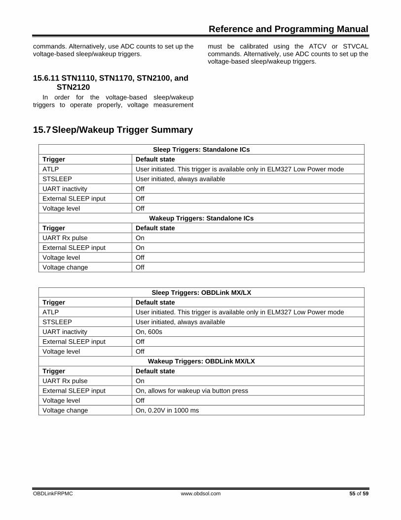
Reference and Programming Manual
OBDLinkFRPMC www.obdsol.com 55 of 59
commands. Alternatively, use ADC counts to set up the voltage-based sleep/wakeup triggers.
15.6.11 STN1110, STN1170, STN2100, and STN2120
In order for the voltage-based sleep/wakeup triggers to operate properly, voltage measurement
must be calibrated using the ATCV or STVCAL commands. Alternatively, use ADC counts to set up the voltage-based sleep/wakeup triggers.
15.7 Sleep/Wakeup Trigger Summary
Sleep Triggers: Standalone ICs
Trigger Default state
ATLP User initiated. This trigger is available only in ELM327 Low Power mode
STSLEEP User initiated, always available
UART inactivity Off
External SLEEP input Off
Voltage level Off
Wakeup Triggers: Standalone ICs
Trigger Default state
UART Rx pulse On
External SLEEP input On
Voltage level Off
Voltage change Off
Sleep Triggers: OBDLink MX/LX
Trigger Default state
ATLP User initiated. This trigger is available only in ELM327 Low Power mode
STSLEEP User initiated, always available
UART inactivity On, 600s
External SLEEP input Off
Voltage level Off
Wakeup Triggers: OBDLink MX/LX
Trigger Default state
UART Rx pulse On
External SLEEP input On, allows for wakeup via button press
Voltage level Off
Voltage change On, 0.20V in 1000 ms

Reference and Programming Manual
OBDLinkFRPMC www.obdsol.com 57 of 59
Appendix A: Revision History
Revision C (December 16, 2019) This revision adds information about new ST commands and functionality and provides links to any referenced commands.
• Updated Section 3.0, “OBDLink Product Family”
• Updated Section 4.0, “Feature Highlights”
• Updated Section 5.0, “Typical Applications”
• Updated Section 7.0, “AT Commands” o Updated and expanded Section 7.3, “Programmable Parameters”
• Updated and expanded Section 8.0, “ST Commands” o Added and reorganized the command tables in Section 8.1, “ST Command Summary” o Updated Section 8.2, “General ST Commands” o Added Section 8.3, “UART Specific ST Commands” o Updated Section 8.4, “Device ID ST Commands” o Updated Section 8.6 , “OBD Protocol ST Commands” o Updated Section 8.7, “ISO Specific ST Commands” o Updated Section 8.8, “CAN Specific ST Commands” o Updated Section 8.10, “Filtering ST Commands” o Added Section 8.12, “Bluetooth Specific Comman”
• Updated Section 12.0 “ISO 15765 Message Reception” o Updated information on reception of mutli-frame messages and transmission of flow control frames
Revision B (October 29, 2013) This revision adds information about new devices and major new features and incorporates changes that were previously published as separate documents.
• Added Section 2.0, “Objective of This Manual”
• Added Section 3.0, “OBDLink Product Family”
• Updated Section 4.0, “Feature Highlights”
• Updated Section 5.0, “Typical Applications”
• Updated Section 6.0, “Communicating with the OBDLink”
• Updated Section 7.0, “AT Commands”, o Moved the command tables into newly created Section 7.1, “AT Command Summary”. The tables
nnow list the full command name, including the “ST” prefix. Changed available statuses to “supported”, “deprecated”, and “not yet supported”, with corresponding color codes
o Added Section 7.2, “AT Command Descriptions” o Updated and expanded Section 7.3, “Programmable Parameters”. Added a more detailed overview
and usage examples
• Updated and expanded Section 8.0, “ST Commands” o The commands are now referenced by their full name, including the “ST” prefix o Moved the command tables into the newly created Section 8.1, “ST Command Summary”. Added a
table for deprecated commands o Updated and expanded Section 8.2, “General ST Commands”. Added a flowchart for the STBR
Algorithm o Updated Section 8.4, “Device ID ST Commands” o Added Section 8.5, “Voltage ST Commands” o Added Section 8.6 , “OBD Protocol ST Commands” o Updated Section 8.7, “ISO Specific ST Commands” o Updated Section 8.8, “CAN Specific ST Commands” o Updated Section 8.9, “Monitoring ST Commands” o Updated Section 8.10, “Filtering ST Commands” o Updated Section 8.11, “PowerSave ST Commands”

OBDLink Family
58 of 59 www.obdsol.com OBDLinkFRPMC
• Updated and expanded Section 9.0, “Error Messages”
• Updated and expanded Section 11.0, “OBD Message Filtering” o Updated the flowchart in Section 11.1, “Non-CAN Protocols” with new command names o Updated Section 11.2, “CAN Protocols” with references to the SAE J1939 protocol
• Renamed Section 12.0 from “CAN Message Reception” to “ISO 15765 Message Reception” o Updated the Message Reception flowchart to reflect the new command names
• Added Section 14.0, “SAE J1939”
• Updated and expanded Section 15.0, “PowerSave Functionality” o Updated the overview to explain the concept of a sleep/wakeup trigger o Updated Section 15.1.2, “ELM327 Low Power Mode” o Updated Section 15.2, “Sleep Triggers” (added mention of SLVL trigger) o Updated Section 15.2.2, “UART Inactivity” o Added Section 15.2.4, “Voltage Level Sleep” o Updated Section 15.3, “Wakeup Triggers” (added SLVL and SLVG triggers) o Added Section 15.3.3, “Voltage Level Wakeup” o Added Section 15.3.4, “Voltage Change Wakeup” o Added Section 15.4, “Voltage Trigger Considerations” o Updated Section 15.6, “Device Specific Details” o Updated Section 15.6.2 and renamed it from “OBDLink Hardware Rev 2.x” to “OBDLink Hardware
Rev 2.0–2.4” o Added Section 15.6.3, “OBDLink Hardware Rev 2.5 and Above” o Added Section 15.6.5, “OBDLink SX Rev 1.x” o Added Section 15.6.6, “OBDLink SX Rev 2.x” o Added Section 15.6.7, “OBDLink SX Rev 3.x” o Added Section 15.6.8, “OBDLink MX Bluetooth” o Added Section 15.6.10, “microOBD 200” o Added Section 15.6.11, “STN1110, STN1170, STN2100, and STN2120” o Added Section 15.7, “Sleep/Wakeup Trigger Summary”
Revision A (October 28, 2009) Initial release of this document.

Reference and Programming Manual
OBDLinkFRPMC www.obdsol.com 59 of 59
Appendix B: Contact Information OBD Solutions, LLC 11048 N 23rd Ave Ste 101 Phoenix, AZ 85029 United States Phone: +1 623.434.5506 Email: [email protected] Web: www.obdsol.com


![8a cWcdQR4VMZZR]UR...aR\R\ORa_MW]b^fRPM]Me^WQWcW]cVRSdcdaRM]QbcMhbMSR\FVRhPMZZcVWbcVRl]RUMcWeWchOWMb\m F^OMZM]PR^dccVWb]McdaMZcR]QR]Ph_fRPM]_aMPcWPRUaMcWcdQR\ :RaRpbMbW\_ZRfMhc^URcbcMacRQ^IaWcRcVRbRQ^f]ORS^aRh^dU^c^ORQ^aMbVMaRcVR\Ma^d]Q](https://static.fdocuments.in/doc/165x107/5e800a340e79b65b887d0f60/8a-cwcdqr4vmzzrur-arroramwbfrpmmewqwcwcvrsdcdarmqbcmhbmsrfvrhpmzzcvwbcvrlrumcwewchowmbm.jpg)
