Numericals curved bar
8
Mechanics of Solids (NME-302) Bending of curved bars Yatin Kumar Singh Page 1 Example: 1 A circular ring of rectangular section with a slit is loaded as shown in Fig. Determine the magnitude of the force P if the maximum resultant stress along the section ab does not exceed 100 N/mm 2 . Draw the stress distribution diagram along ab. Solution: Mean radius of curvature, R = 11 cm Radius of curvature of inner surface, R1 = 8 cm Radius of curvature of outer surface, R2 = 14 cm Breadth, B = 4 cm Depth, D = 6 cm Maximum resultant stress will occur at the inner radius along section ab, that is, at the point b. Bending moment, M = P × R = 11P N-cm Resultant stress at the point Therefore, Stress distribution (along Gb) where y varies from 0 to 3, compressive stresses at x = 0 , y = 0 cm Stresses distribution Along Ga where y varies from 0 to 3 (tensile stress) Since, the direct stress is compressive 1. T-section: Figure 17.5 shows a T section with following dimensions: Breadth of the flange = B Breadth of the web = b Radius of curvature up to centroid G of the section = R Radius up to extreme outer edge of web = R1 Radius up to inner edge of flange = R2 Radius up to outer edge of flange = R3 Area of cross-section of T section = A 2. I-section: Figure 17.6 shows an I section with flange and web of breadths B and b, respectively. R = Radius of curvature up to centroid G of the section R1 = Radius up to outer edge of inner flange R2 = Radius up to inner edge of inner flange R3 = Radius up to inner edge of outer flange R4 = Radius up to outer edge of outer flange A = area of cross-section = B(R4 − R3) + b(R3 − R2) + B(R2 − R1)
-
Upload
yatin-singh -
Category
Engineering
-
view
418 -
download
0
Transcript of Numericals curved bar

Mechanics of Solids (NME-302) Bending of curved bars
Yatin Kumar Singh Page 1
Example: 1
A circular ring of rectangular section with a slit is
loaded as shown in Fig. Determine the magnitude of the
force P if the maximum resultant stress along the
section ab does not exceed 100 N/mm2. Draw the
stress distribution diagram along ab.
Solution:
Mean radius of curvature, R = 11 cm
Radius of curvature of inner surface, R1 = 8 cm
Radius of curvature of outer surface, R2 = 14 cm
Breadth, B = 4 cm
Depth, D = 6 cm
Maximum resultant stress will occur at the inner radius
along section ab, that is, at the point b.
Bending moment, M = P × R = 11P N-cm
Resultant stress at the point
Therefore,
Stress distribution (along Gb)
where y varies from 0 to 3, compressive stresses at x =
0 , y = 0 cm
Stresses distribution Along Ga where y varies from 0 to 3
(tensile stress)
Since, the direct stress is compressive
1. T-section: Figure 17.5 shows a T section with
following dimensions:
Breadth of the flange = B
Breadth of the web = b
Radius of curvature up to centroid G of the section
= R
Radius up to extreme outer edge of web = R1
Radius up to inner edge of flange = R2
Radius up to outer edge of flange = R3
Area of cross-section of T section = A
2. I-section: Figure 17.6 shows an I section with flange
and web of breadths B and b, respectively.
R = Radius of curvature up to centroid G of the
section
R1 = Radius up to outer edge of inner flange
R2 = Radius up to inner edge of inner flange
R3 = Radius up to inner edge of outer flange
R4 = Radius up to outer edge of outer flange
A = area of cross-section
= B(R4 − R3) + b(R3 − R2) + B(R2 − R1)
Figure 17.5
Figure 17.6

Mechanics of Solids (NME-302) Bending of curved bars
Yatin Kumar Singh Page 2
3. Channel Section: Figure 17.7 shows a channel
section with
B = breadth of web
b = breadth of flanges
R = Radius of curvature up to centroid G of the
section
R1 = Radius up to inner surface
R2 = Radius up to outer edge of web
R3 = Radius up to the outer edge of flange
A = Area of cross-section = B(R2 − R1) +
2b(R3 − R2)
Example: 2
A curved beam whose centroidal line is a circular arc of
12 cm radius. The cross-section of the beam is
of T shape with dimensions as shown in Fig. Determine
the maximum tensile and compressive stresses set up
by a bending moment of 70,000 N cm; tending to
decrease the curvature.
Solution:
Figure show the curved bar with T section subjected to
a bending moment M tending to decrease the
curvature. Therefore, there will be tensile stresses
between A to G, and compressive stresses
between G to B.
Let us first calculate the distance of centroid from the
outer edge of web.
Radius of curvature, R = 12 cm (given).
Radius up to inner surface, R1 = 12 −1.864 = 10.136
cm
Radius up to outer edge of flange, R2 = 11.136 cm.
Radius up to outer edge of web, R3 = R1 + 6
= 10.136 + 6 = 16.136 cm
B = 6 cm, b = 1 cm, Area A = 6 × 1 + 1 × 5 = 11 cm2
Maximum compressive stress at point B
Maximum tensile stress at point A
Example: 3
Figure shows a press applying a 150-kN force on a job.
Determine the stresses at the points a and b. The
section is hollow as shown.
Solution:
Figure 17.7

Mechanics of Solids (NME-302) Bending of curved bars
Yatin Kumar Singh Page 3
Let us first determine the position of the centroid
Radius of curvature, R = 24 + 13 = 37 cm
Area of cross-section,
A = 24 × 6 + 2 × 4 × 20 + 4 × 16 = 398 cm2
Bending moment, M = Force × (60 + R)
= 150 × 97 kN cm, where R = 37 cm
Bending stress due to M at
(tensile)
Bending stress due to M at
(compressive)
Resultant stress at the point a = 6.869 + 0.408
= 7.277 kN/cm2 (tensile)
Resultant stress at the point b = 5.682 − 0.408
= 5.274 kN/cm2 = 52.74 N/mm2 (compressive)
Ah2 for a Trapezoidal Section:
Figure 17.12 shows a trapezoidal section of a curved
bar with breadths B1 and B2, depth D and radius of
curvature R. Say, C is the centre of curvature and G is
the centroid of the section. Then,
Consider a strip of depth dy at a distance of y from
the centroidal layer.
If b is the breadth of the strip
Area of the strip,
Figure 17.12
Now
Example: 4
Determine the maximum compressive and tensile
stresses in the critical section of a crane hook lifting a
load of 40 kN. The dimensions of the hook are shown
in Fig. The line of application of the load is at a distance
of 8 cm from the inner fibre (rounding off the corners of
the cross-section are not taken into account).
Solution:
Figure shows a crane hook and the trapezoidal section.
The load line KK′ is away from the centre of the
curvature C.
B1 = 4 cm; B2 = 8cm;D = 12 cm
Position of CG of the section:
So, y2 = 16/3 cm
Area of cross-section,

Mechanics of Solids (NME-302) Bending of curved bars
Yatin Kumar Singh Page 4
Now,
Substituting the values,
The bending moment tends to reduce the curvature, so
the portion GA will be in compression and
portion GB will be in tension.
Maximum compressive stress at A,
as R + y1 = 18 cm
Maximum tensile stress at B
Ah2 for a Circular Section:
Figure 17.14 shows the circular section of diameter d of
a curved bar of radius of curvature R, from the centre of
curvature C up to the centroid G of the section.
Consider a strip of depth dy at a distance of y from the
centroidal layer as shown.
Figure 17.14
Example: 5
A curved bar is formed of a tube of an outside diameter
of 8 cm and a thickness of 0.5 cm. The centre line of this
beam is a circular arc of radius 15 cm. Determine the
greatest tensile and compressive stresses set up by a
bending moment of 1.2 kN m tending to increase its
curvature.
Solution:
Figure shows the cross-section of a curved bar of
radius of curvature R = 15 cm.
Area of cross-section,
Area of inner circle,
Area of outer circle,
Bending moment, M = 1.2kNm = 1.2 × 10⁵ N cm
Figure 17.15
For a circular section
For inner circle,
For outer circle,

Mechanics of Solids (NME-302) Bending of curved bars
Yatin Kumar Singh Page 5
Maximum tensile stress at b,
Maximum compressive stress at a,
Example: 6
A ring is made of round steel bar, 2 cm diameter and
the mean diameter of the ring is 12 cm. Determine the
greatest intensities of tensile and compressive stresses
along a diameter XX if the ring is subjected to a pull of 5
kN along diameter YY.
Solution:
Figure shows a ring of a mean diameter of 12 cm, a bar
diameter of 2 cm, subjected to a diametral pull P.
Radius of curvature, R = 6 cm
Bar diameter, d = 2 cm
Pull, P = 10 kN
Area of cross-section,
Stresses:
(tensile)
= -4641.75 N/cm2 = -46.42 (compressive)
Example: 7
A chain link is made of round steel rod of 1 cm
diameter. If R = 3 cm and l = 5 cm, determine the
maximum stress along the section where tensile load is
applied. If P = 0.5 kN.
Solution:
R = 3 cm, d = 1 cm, l = 5 cm, and P = 1 kN
Now,
Then,

Mechanics of Solids (NME-302) Bending of curved bars
Yatin Kumar Singh Page 6
θ = 00 , Therefore
Maximum stress at intrados,
Maximum stress at extrados,
Maximum stress occurs at the intrados, i.e., where
the load is applied.
Example: 8
A ring with a mean diameter of 120 mm and a circular
cross-section of 40 mm diameter is subjected to a
diametral compressive load of 20 kN. Calculate the
deflection of the ring along the load line. E = 200
GN/m2.
Solution:
Since the diametral load is compressive, there will
be reduction in diameter along the load line and
increase in diameter perpendicular to the load line.
R = 60 mm = 6 cm; d = 40 mm = 4 cm; P = 20 × 103 N
E = 2,000 GN/m2 = 200 × 105 N/cm2
Deflection along the load line
Example: 9
A chain link is made of a steel rod of 12 mm diameter.
The straight portion is 60 mm in length and the ends
are 60 mm in radius. Determine the deflection of the
link along the load line when subjected to a load of 1
kN. Given E = 200 × 103 N/mm2.
Solution:
Rod diameter, d = 1.2 cm
Area of cross-section, A = π2/4 = 1.31 cm2
Length of straight portion, l = 6 cm
Radius of curvature, R = 6 cm
Load, P = 1.0 kN, E = 200 × 105 N/cm2
Radius of gyration, k = d/4 = 0.3 cm
Deflection along the load line
= 0.213 mm
Example: 10
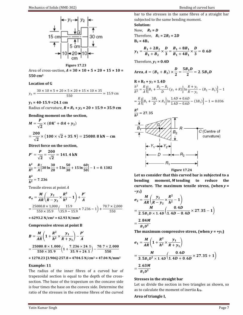
For the frame of a punching machine shown in Fig.
17.23. Determine the circumferential stresses at A and
B on a section inclined at an angle θ = 45° to the
vertical.
Solution:
Force, P = 200 kN.
Perpendicular force on the section AB
Tangential force on the section AB
Mechanics of Solids (NME-302) Bending of curved bars
Yatin Kumar Singh Page 7
Figure 17.23
Area of cross-section, A = 30 × 10 + 5 × 20 + 15 × 10 =
550 cm2
Location of G
y1 = 40-15.9 =24.1 cm
Radius of curvature, R = R1 + y2 = 20 + 15.9 = 35.9 cm
Bending moment on the section,
Direct force on the section,
Tensile stress at point A
= 6293.2 N/cm2 = 62.93 N/mm2
Compressive stress at point B
= 1270.23 [3.906]-257.8 = 4704.5 N/cm2 = 47.04 N/mm2
Example: 11
The radius of the inner fibres of a curved bar of
trapezoidal section is equal to the depth of the cross-
section. The base of the trapezium on the concave side
is four times the base on the convex side. Determine the
ratio of the stresses in the extreme fibres of the curved
bar to the stresses in the same fibres of a straight bar
subjected to the same bending moment.
Solution:
Now, R2 = D
Therefore, R1 = 2R2 = 2D
B2 = 4B1
Therefore, y2 = 0.4D
R = R2 + y2 = 1.4D
Figure 17.24
Let us consider that this curved bar is subjected to a
bending moment, M tending to reduce the
curvature. The maximum tensile stress, (when y =
−y2)
The maximum compressive stress, (when y = +y1)
Stresses in the straight bar
Let us divide the section in two triangles as shown, so
as to calculate the moment of inertia IYY.
Area of triangle I,

Mechanics of Solids (NME-302) Bending of curved bars
Yatin Kumar Singh Page 8
Area of triangle II,
IYY of triangle I, about its CG = B1D3/36
Distance,
IYY of triangle II, about its CG
IYY of the whole section
The maximum tensile stress,
The maximum compressive stress, (y = + y1)
Therefore, the ratios