Aerospace Composites Design Numericals
30
Material E (psi) Area (in 2 ) A(equir) A 8 X 10 6 .25 .25 (8/12) = .167 B 12 X 10 6 .25 .25 (12/12) = .25 EXAMPLE 4 A Sandwich structure is subjected to 2000 lb/in load in the laminate causes extension (no bending) as above Determine the tensile force in each laminate. Determine the average tensile stress in each laminate. Determine the location of the tensile load resultant.
Transcript of Aerospace Composites Design Numericals
Material E (psi) Area (in2 ) A(equir)A 8 X 10⁶ .25 .25 (8/12) = .167B 12 X 106 .25 .25 (12/12) = .25
EXAMPLE 4
A Sandwich structure is subjected to 2000 lb/in load in the laminate causes extension (no bending) as above Determine the tensile force in each laminate. Determine the average tensile stress in each laminate. Determine the location of the tensile load resultant.
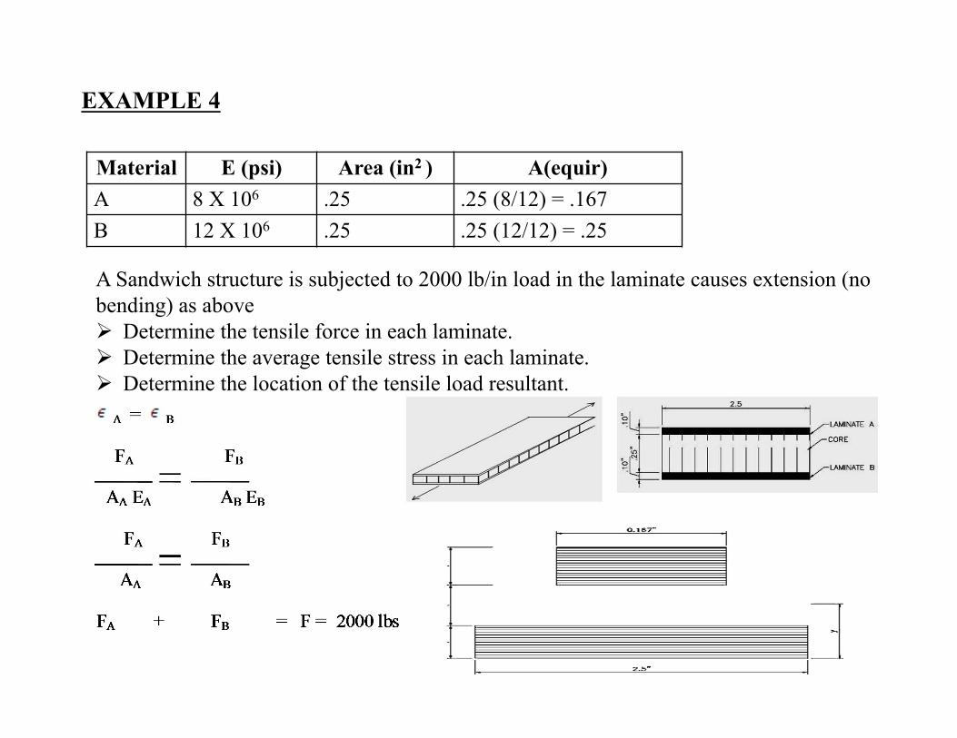
FB = AB x F
AA +AB
FA + AB FA = F
AA
FA = AA x F =
AA + AB
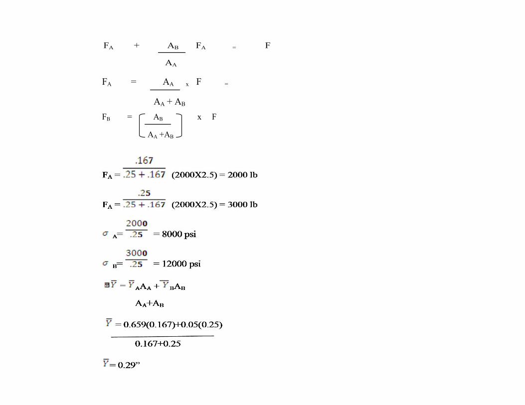
EXAMPLE 5
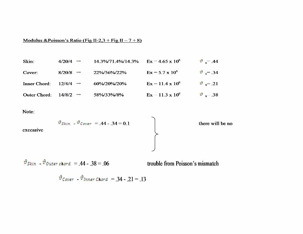
Determine the valve of the ultimate tensile load for this panel based on the strain allowable (Table II-3) Assume that bending stresses are negligible.
Skin + Cover: Gr-Ep, Type IV, Class 2, style 3k-70-pw Inner + outer chords : Gr-Ep, Type III, Class 1, Grade 145
Thickness (Table II-1)
Skin: 2/10/2 14(.0083) =0 .116”
Cover: 18(.0083) = 0.149”
Inner Chord: 20(.0059) = 0.118”
Outer Chord: 24(.0059) = 0.142”
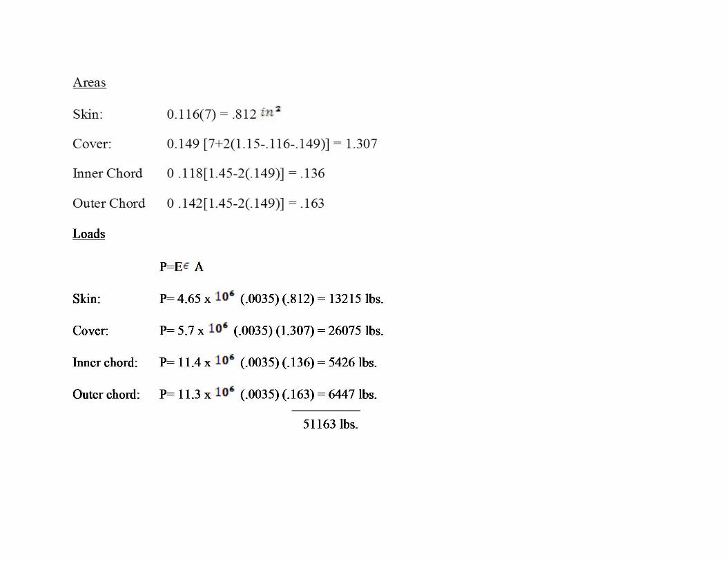
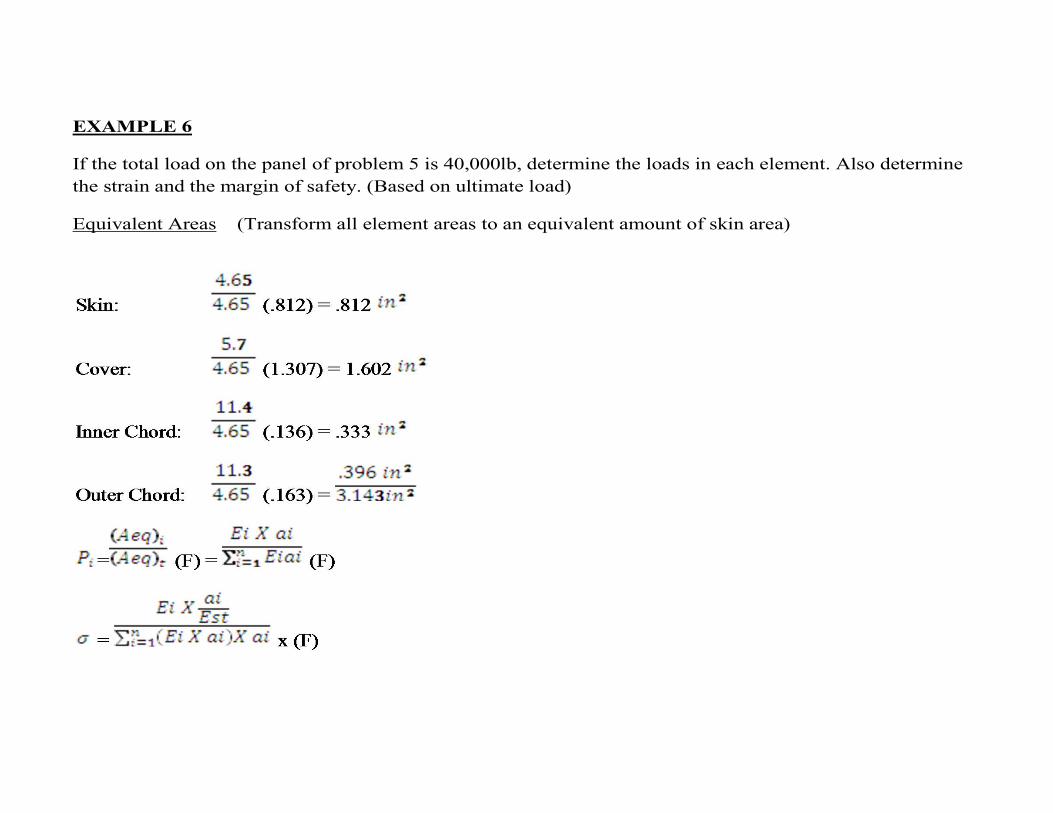
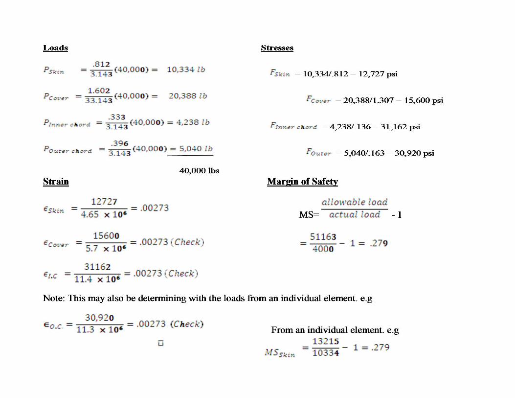
EXAMPLE 6
If the total load on the panel of problem 5 is 40,000lb, determine the loads in each element. Also determine the strain and the margin of safety. (Based on ultimate load)
Equivalent Areas (Transform all element areas to an equivalent amount of skin area)
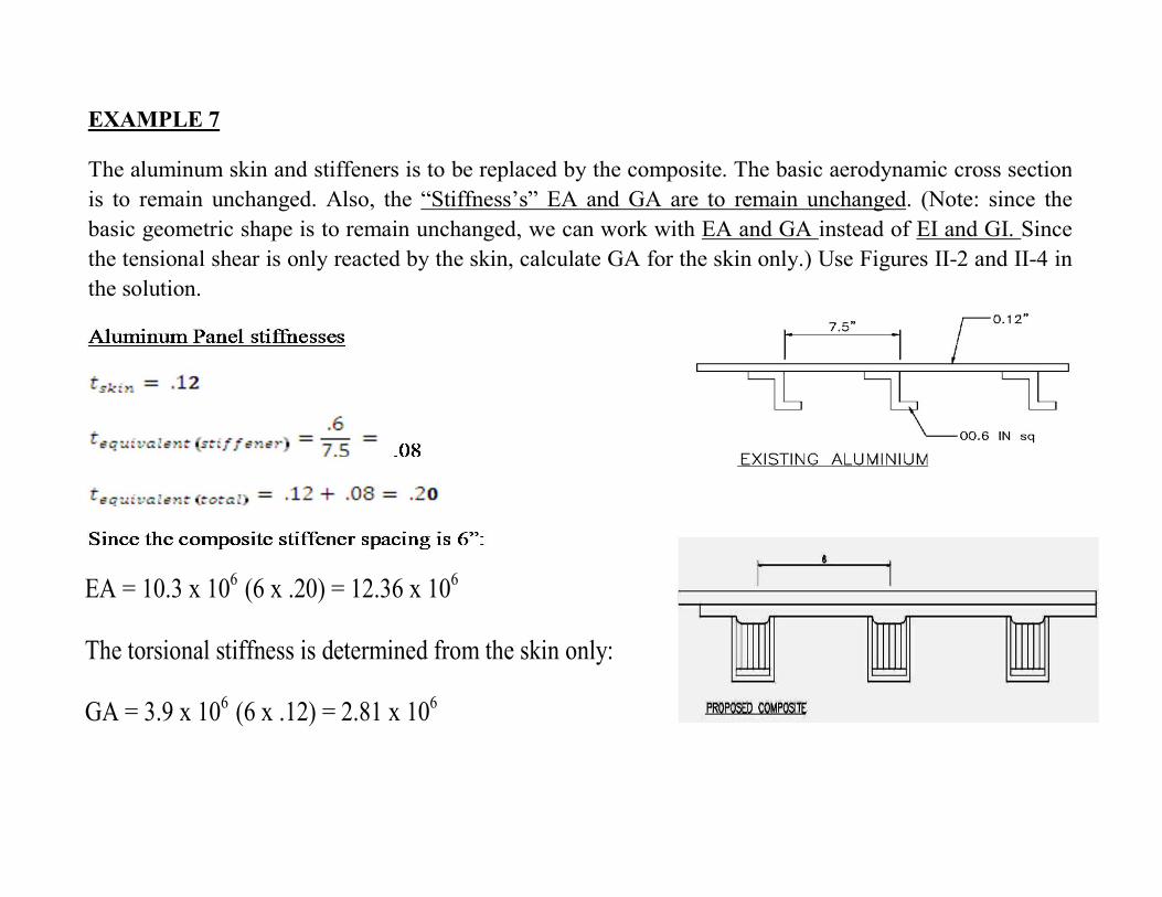
EXAMPLE 7
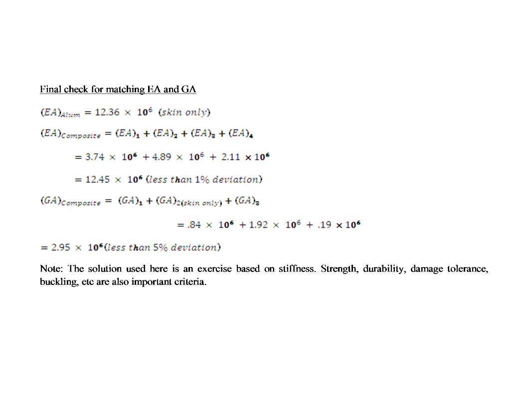
The aluminum skin and stiffeners is to be replaced by the composite. The basic aerodynamic cross section is to remain unchanged. Also, the “Stiffness’s” EA and GA are to remain unchanged. (Note: since the basic geometric shape is to remain unchanged, we can work with EA and GA instead of EI and GI. Since the tensional shear is only reacted by the skin, calculate GA for the skin only.) Use Figures II-2 and II-4 in the solution.
EA = 10.3 x 10⁶ (6 x .20) = 12.36 x 10⁶
The torsional stiffness is determined from the skin only:
GA = 3.9 x 10⁶ (6 x .12) = 2.81 x 10⁶
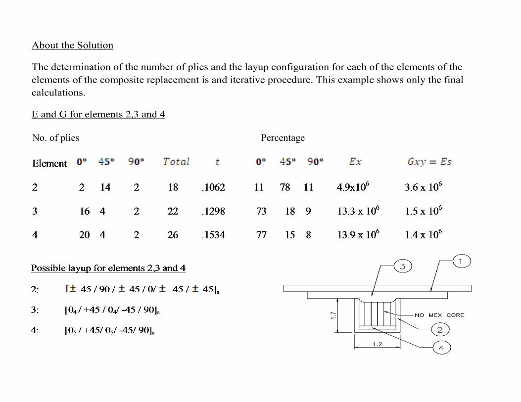
About the Solution
The determination of the number of plies and the layup configuration for each of the elements of the elements of the composite replacement is and iterative procedure. This example shows only the final calculations.
E and G for elements 2,3 and 4
No. of plies Percentage
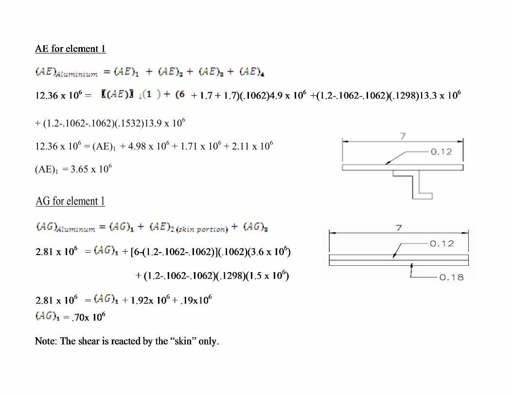
+ (1.2-.1062-.1062)(.1532)13.9 x 10⁶
12.36 x 106 = (AE)1 + 4.98 x 10⁶ + 1.71 x 10⁶ + 2.11 x 10⁶
(AE)1 = 3.65 x 10⁶
AG for element 1
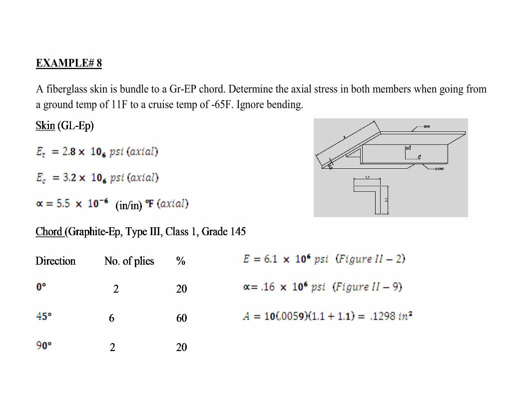
EXAMPLE# 8
A fiberglass skin is bundle to a Gr-EP chord. Determine the axial stress in both members when going from a ground temp of 11F to a cruise temp of -65F. Ignore bending.
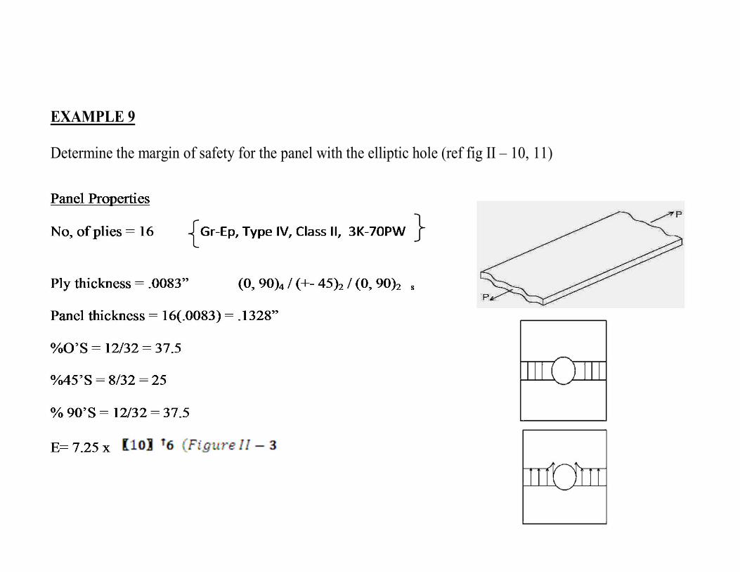
EXAMPLE 9
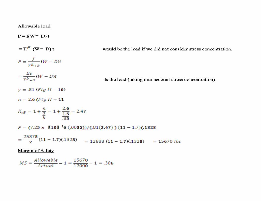
Determine the margin of safety for the panel with the elliptic hole (ref fig II – 10, 11)
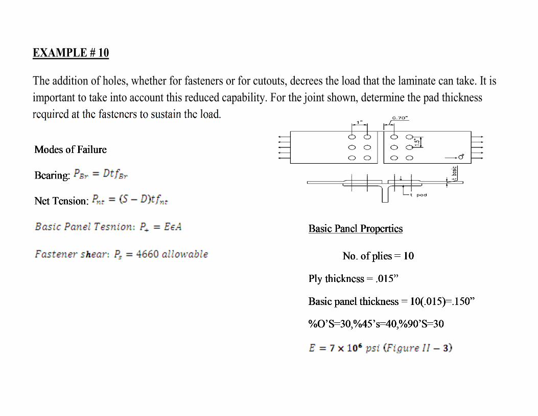
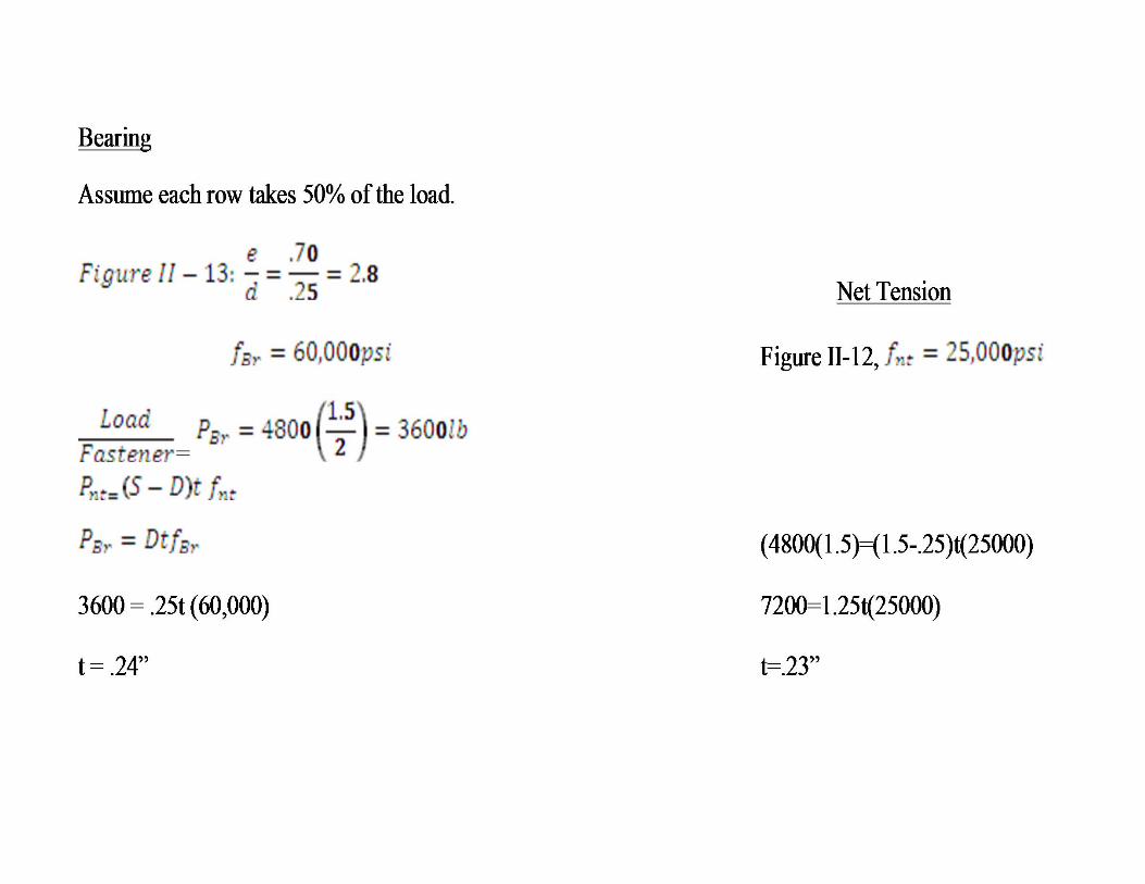
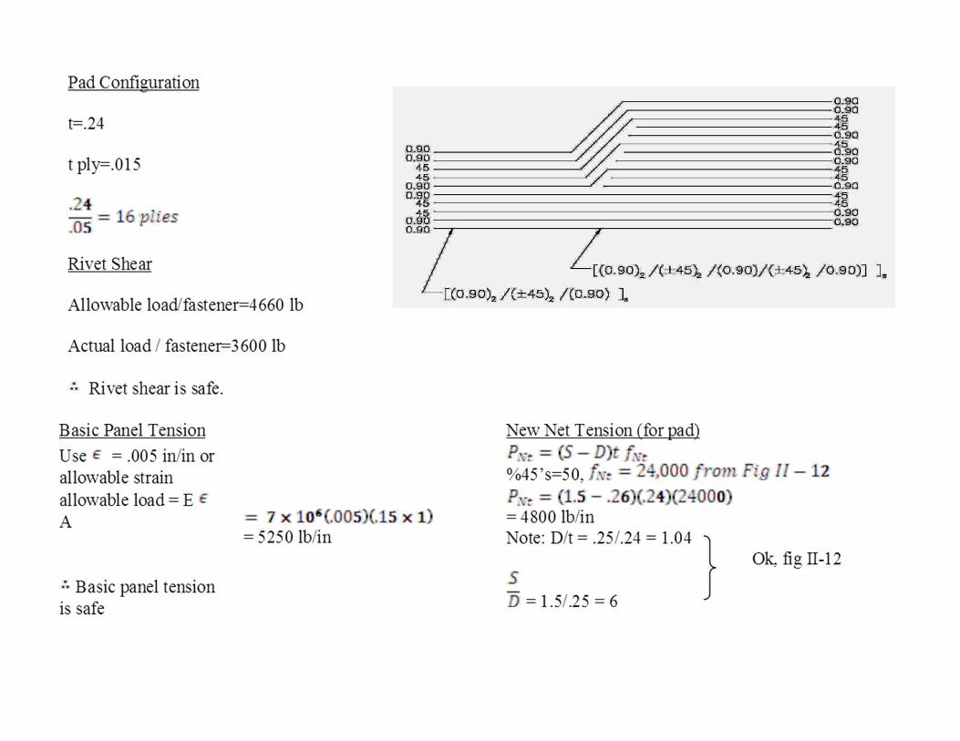
EXAMPLE # 10
The addition of holes, whether for fasteners or for cutouts, decrees the load that the laminate can take. It isimportant to take into account this reduced capability. For the joint shown, determine the pad thickness required at the fasteners to sustain the load.

Example 11
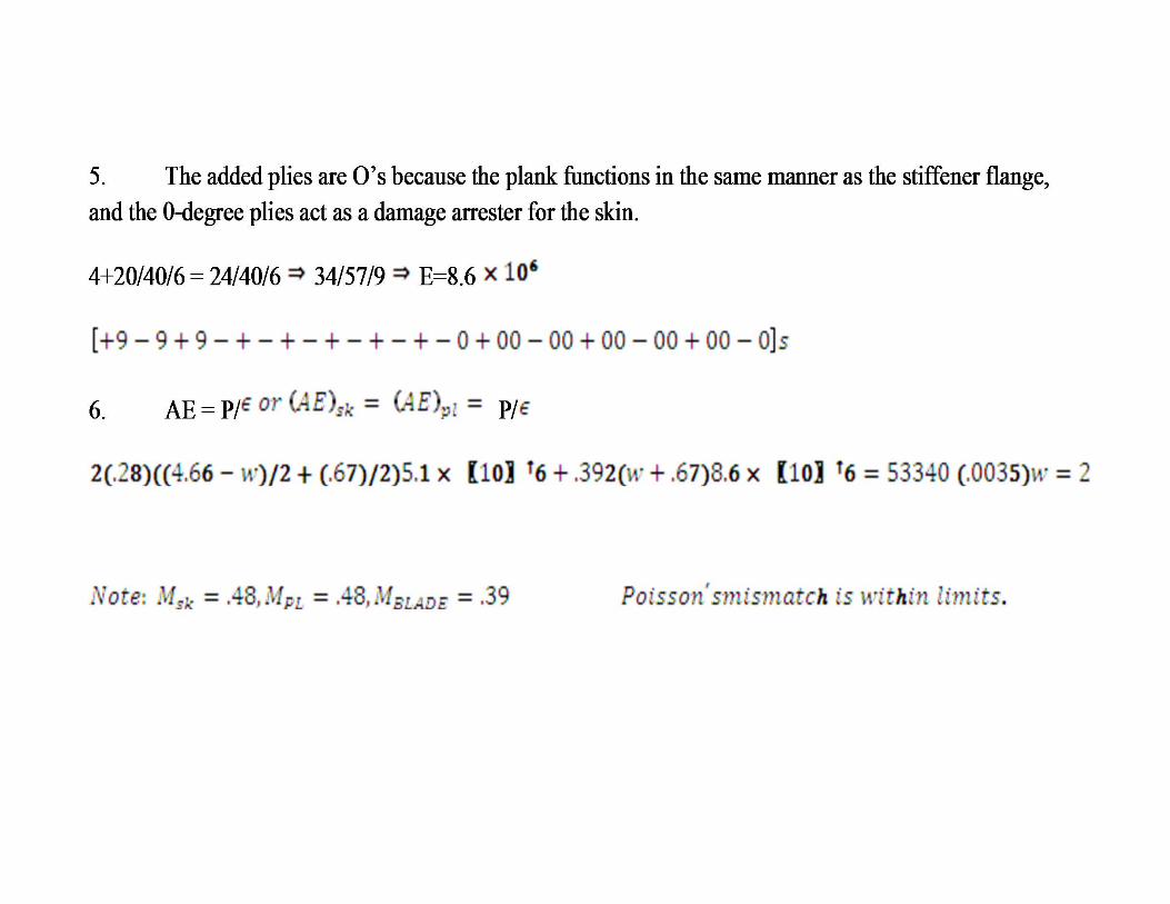
Design a blade – stiffened tension panel from Gr-EP, Type II, Class 1 and Grade 145
The skin is to contain integral built-up planks for damage arrestment.
Stiffener spacing is 6”
Running load is 12, 700 lb/in
Strain allowable is .0035 in/in (Table II -3)
The skin-plank is to carry 70% of the total section load.

Skin and Plank
Unknowns:
1. ts --------------------------- try 50 plies
2. tp --------------------------- try 70 plies, the added plies are 0’s
3. d --------------------------- Ply drop off = 6 plies per .2”
4. Es --------------------------- 10/80/10 percentage
5. Ep --------------------------- The skin is to contain the integral built-up plank of
interleaved 0-degree plies for crack
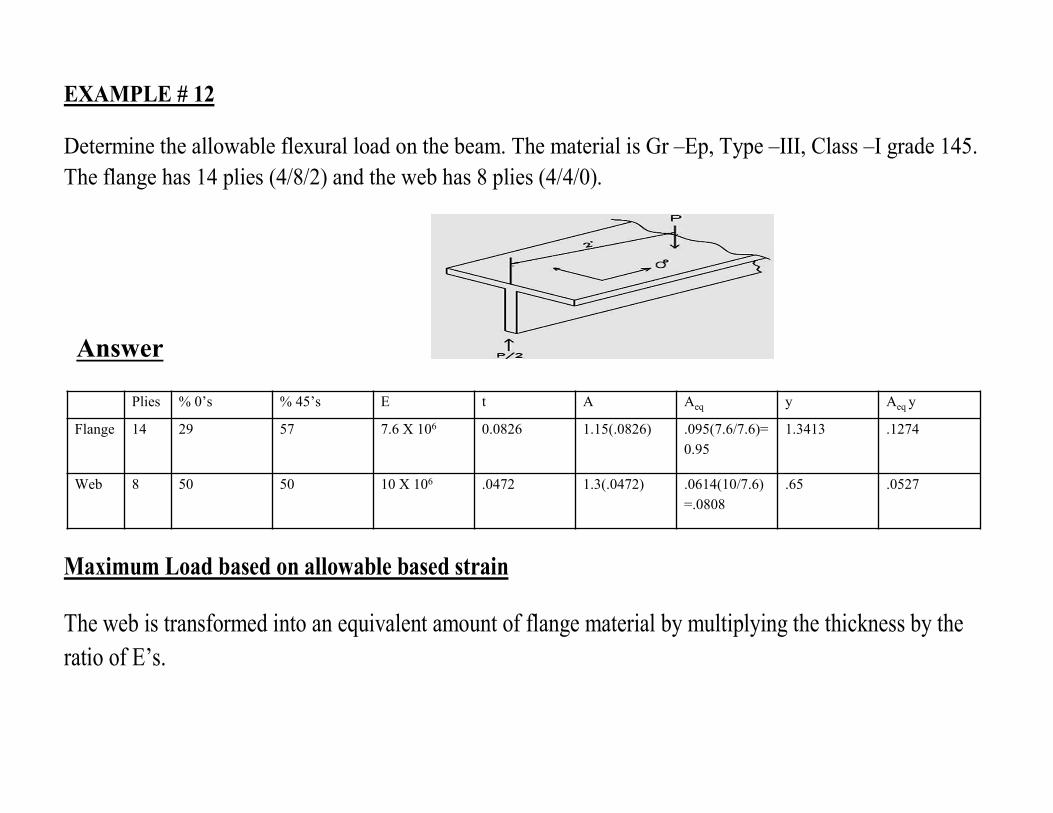
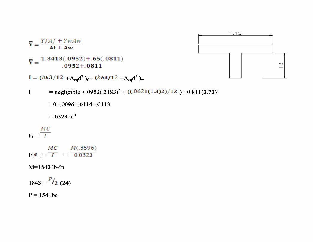
EXAMPLE # 12
Determine the allowable flexural load on the beam. The material is Gr –Ep, Type –III, Class –I grade 145. The flange has 14 plies (4/8/2) and the web has 8 plies (4/4/0).
Plies % 0’s % 45’s E t A Aeq y Aeq y
Flange 14 29 57 7.6 X 10⁶ 0.0826 1.15(.0826) .095(7.6/7.6)=0.95
1.3413 .1274
Web 8 50 50 10 X 106 .0472 1.3(.0472) .0614(10/7.6)=.0808
.65 .0527
Answer
Maximum Load based on allowable based strain
The web is transformed into an equivalent amount of flange material by multiplying the thickness by the ratio of E’s.
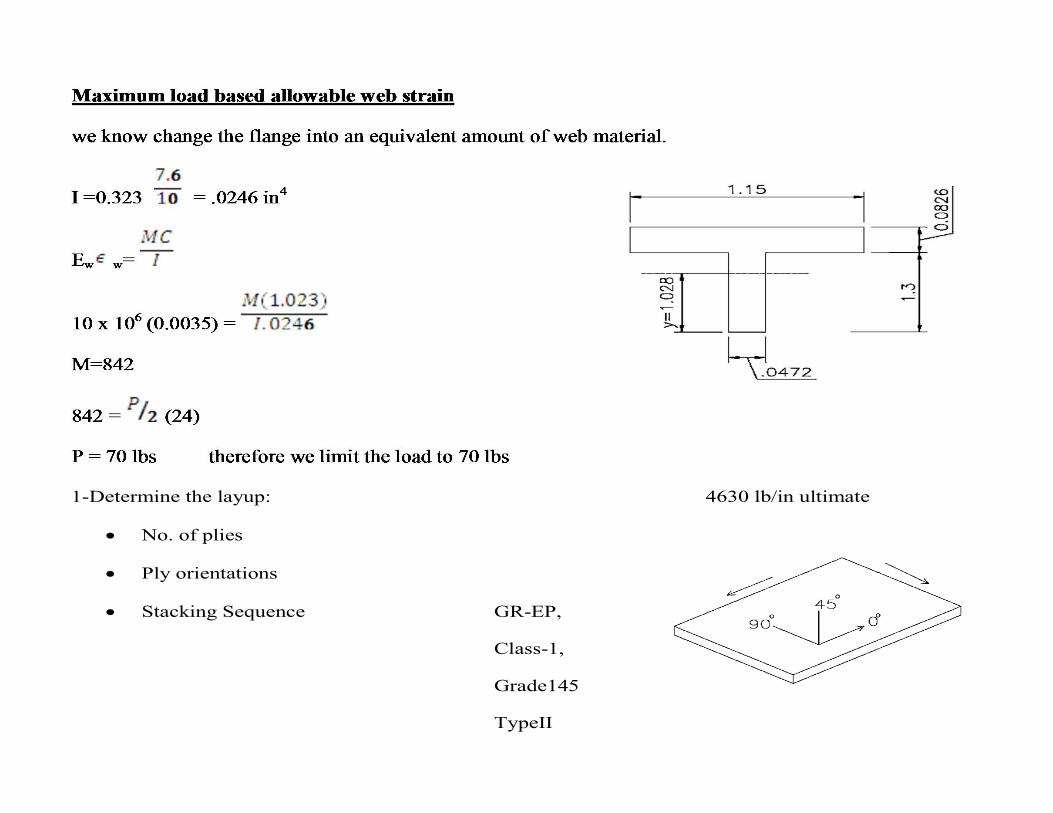
1-Determine the layup: 4630 lb/in ultimate
No. of plies
Ply orientations
Stacking Sequence GR-EP,
Class-1,
Grade145
TypeII
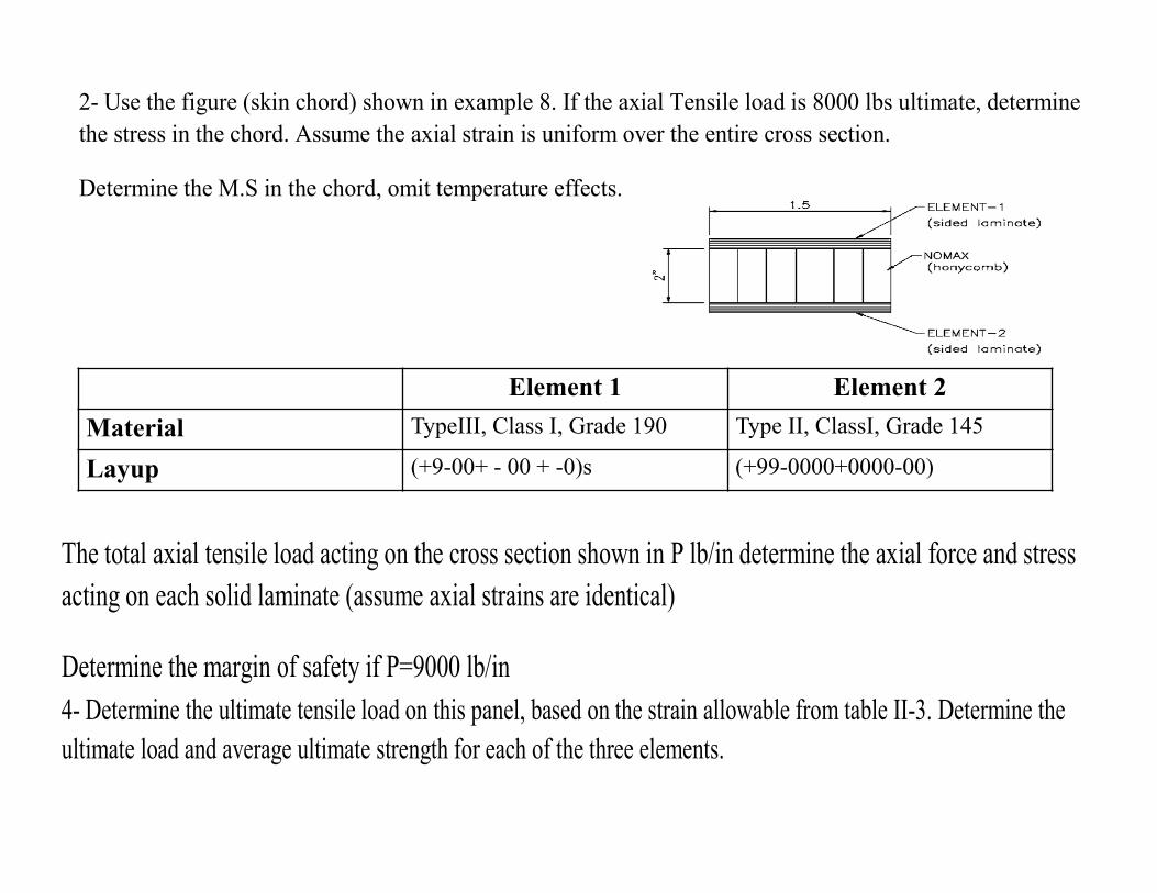
2- Use the figure (skin chord) shown in example 8. If the axial Tensile load is 8000 lbs ultimate, determine the stress in the chord. Assume the axial strain is uniform over the entire cross section.
Determine the M.S in the chord, omit temperature effects.
Element 1 Element 2Material TypeIII, Class I, Grade 190 Type II, ClassI, Grade 145
Layup (+9-00+ - 00 + -0)s (+99-0000+0000-00)
The total axial tensile load acting on the cross section shown in P lb/in determine the axial force and stress acting on each solid laminate (assume axial strains are identical)
Determine the margin of safety if P=9000 lb/in 4- Determine the ultimate tensile load on this panel, based on the strain allowable from table II-3. Determine the ultimate load and average ultimate strength for each of the three elements.
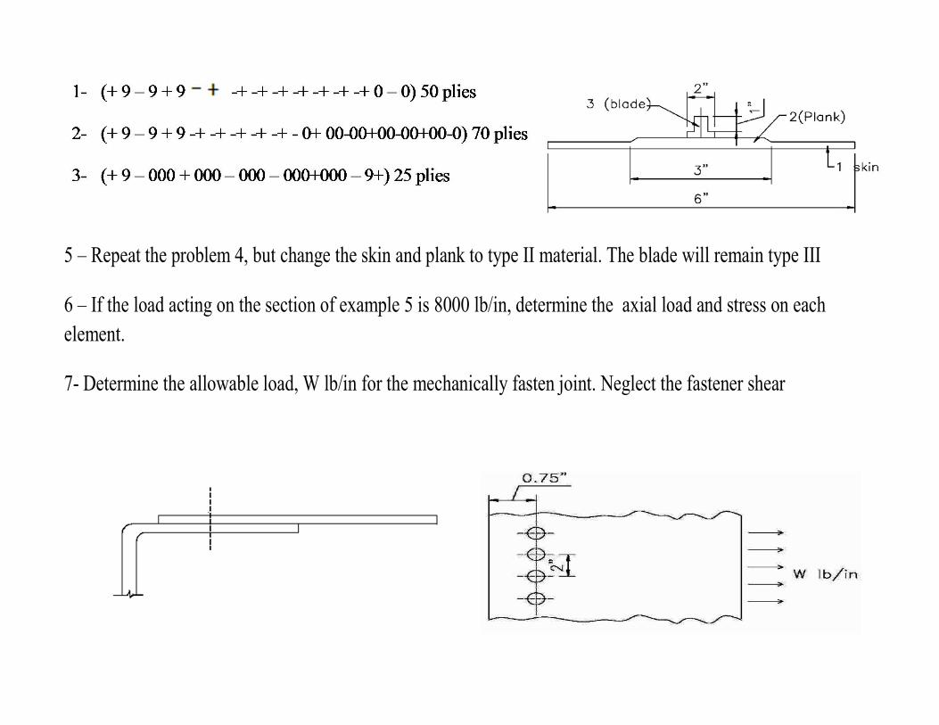
5 – Repeat the problem 4, but change the skin and plank to type II material. The blade will remain type III
6 – If the load acting on the section of example 5 is 8000 lb/in, determine the axial load and stress on each element.
7- Determine the allowable load, W lb/in for the mechanically fasten joint. Neglect the fastener shear

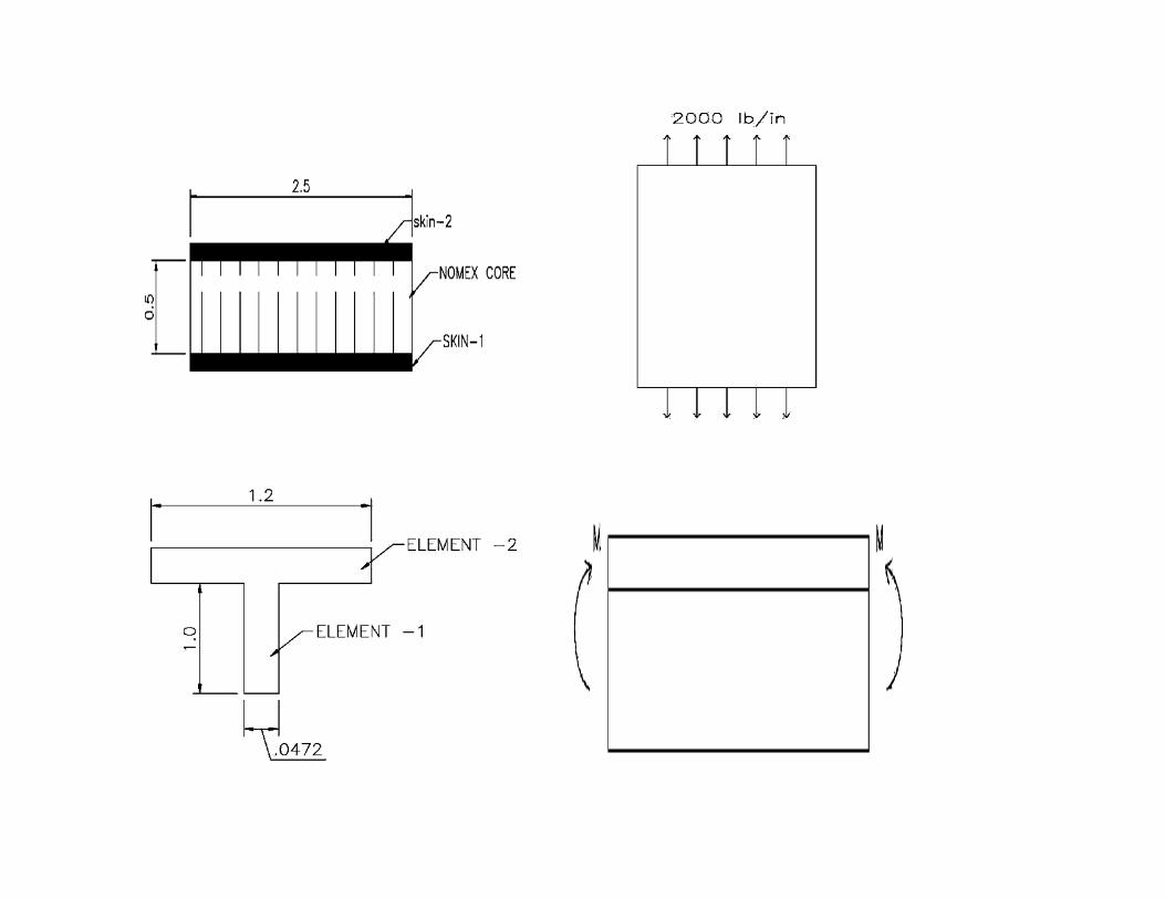
9‐
Skin1 Skin 2Material Type III, Class I, Grade 95 Type III, Class I, Grade 95
Layup (+9, 00)s (+ 9, 000 )
The sandwich panel is subjected to an axial load of 2000 lb/in as shown. Determine the axial force carried by each skin ) assume uniform strain over the cross section) determine the stress resultant in skin I. include in your description a flow chart of the analysis.
Use the same material and layup information as given in problem -3.
Determine the average compressive stress in element- 2 from the moment M in-lbs
Determine the maximum tensile stress in element 1 from the bending moment M
Determine the allowable value for M based on the strains given in table II-3

Answers: