
Numerical simulation of flatback airfoil aerodynamic …aancl.snu.ac.kr/aancl/research/International...
10
Numerical simulation of flatback airfoil aerodynamic noise Taehyung Kim a , Minu Jeon a , Soogab Lee a, b , Hyungki Shin c, * a Department of Mechanical and Aerospace Engineering, Seoul National University,1 Gwanak-ro, Gwanak-gu, Seoul 151-742, South Korea b Institute of Advanced Aerospace Technology, Department of Mechanical and Aerospace Engineering, Seoul National University, 1 Gwanak-ro, Gwanak-gu, Seoul 151-742, South Korea c Energy Efficiency Department, Korea Institute of Energy Research, 152 Gajeong-ro, Yuseong-gu, Daejeon 305-343, South Korea article info Article history: Received 21 February 2013 Accepted 23 August 2013 Available online 17 September 2013 Keywords: Large wind turbine Flatback airfoil Root blade Aerodynamic noise abstract The present paper presents a possible path for developing a large eddy simulation (LES) applicable to high Reynolds-number complex turbulent flows and the performance of the coupling of LES with sta- tistical turbulence models around the flow over a blunt trailing edge configuration. The turbulent fluc- tuations in the boundary layers at the inflow region of the LES domain are generated by a synthesized turbulence method. The hybrid RANS-LES model showed considerable improvement in prediction ac- curacy even at a moderate grid resolution. The aerodynamic comparison with experimental data shows like results for the pressure distributions surrounding a flatback airfoil. To predict accurately the noise radiation from the blunt trailing edge and to save computational costs, the near-field region is computed by embedded LES while the surrounding region is simultaneously computed by RANS. The Brooks, Pope, and Marcolini (BPM) semi-empirical model is used for noise comparison with the hybrid RANS-LES result and experimental data. The present hybrid RANS-LES method is found to be adequate for predicting aerodynamic noise generation by vortical flow in the vicinity of a blunt trailing edge airfoil over a range of frequencies. Ó 2013 Elsevier Ltd. All rights reserved. 1. Introduction The inboard region of large wind turbine blades requires thick airfoils to meet structural requirements. The use of flatback airfoils permits the use of airfoils of increased thickness without the chord increases that would occur if thick conventional airfoils were used. Avoiding this additional chord length makes the resulting struc- tural design more compact and easier to construct, resulting in a blade that can be more easily transported [1]. Despite their numerous benefits, including the aforementioned structural im- provements, high sectional lift coefficients and a reduction of sensitivity to leading edge surface soiling, flatback airfoils also induce increased blade drag and trailing edge vortex shedding noise. Due to their high Reynolds number, the wake of flatback airfoils is accompanied by three-dimensional instabilities which emerge as pairs of counter-rotating streamwise vortices. These three-dimensional instabilities are dependent on the airfoil’s Rey- nolds number, free stream turbulence and the turbulent layer boundaries at the two ends of the three-dimensional blunt trailing edge of the profiled body [2]. Large eddy simulation (LES) is well known as a useful tool to predict practical turbulence problems. Although LES needs far fewer grid nodes than direct numerical simulation (DNS), there still remain several serious difficulties in its application to high Reynolds-number flows. In LES, only the dissipative scales of turbulence, which are assumed to have a more isotropic char- acter than the large scales in a shear-driven flow, are modeled while the eddies carrying the bulk of the energy of the flow are resolved. However, in the near-wall region, the number of grid points increases drastically because the temporal and spatial scales of the energy-containing eddies become very small. Therefore, LES cannot be applied to large-scale flow problems. To overcome these difficulties, a hybrid RANS/LES model origi- nally based on the concept of a hybrid model connecting LES with Reynolds-Averaged Navier-Stokes (RANS) modeling in the near- wall region has emerged. A number of researchers have explored this concept (Davidson et al. [3], Hanjalic et al. [4], Temmerman et al. [5], Kenichi Abe et al. [6]) with positive results encouraging further development of this field. On the other hand, very few studies have included a detailed description of the near-wall * Corresponding author. Tel.: þ82 42 860 3748; fax: þ82 42 860 3133. E-mail addresses: [email protected] (T. Kim), [email protected] (M. Jeon), [email protected] (S. Lee), [email protected] (H. Shin). Contents lists available at ScienceDirect Renewable Energy journal homepage: www.elsevier.com/locate/renene 0960-1481/$ e see front matter Ó 2013 Elsevier Ltd. All rights reserved. http://dx.doi.org/10.1016/j.renene.2013.08.036 Renewable Energy 65 (2014) 192e201
Transcript of Numerical simulation of flatback airfoil aerodynamic …aancl.snu.ac.kr/aancl/research/International...
lable at ScienceDirect
Renewable Energy 65 (2014) 192e201
Contents lists avai
Renewable Energy
journal homepage: www.elsevier .com/locate/renene
Numerical simulation of flatback airfoil aerodynamic noise
Taehyung Kim a, Minu Jeon a, Soogab Lee a, b, Hyungki Shin c, *
a Department of Mechanical and Aerospace Engineering, Seoul National University, 1 Gwanak-ro, Gwanak-gu, Seoul 151-742, South Koreab Institute of Advanced Aerospace Technology, Department of Mechanical and Aerospace Engineering, Seoul National University, 1 Gwanak-ro,Gwanak-gu, Seoul 151-742, South Koreac Energy Efficiency Department, Korea Institute of Energy Research, 152 Gajeong-ro, Yuseong-gu, Daejeon 305-343, South Korea
a r t i c l e i n f o
Article history:Received 21 February 2013Accepted 23 August 2013Available online 17 September 2013
Keywords:Large wind turbineFlatback airfoilRoot bladeAerodynamic noise
* Corresponding author. Tel.: þ82 42 860 3748; faxE-mail addresses: [email protected] (T. Kim),
[email protected] (S. Lee), [email protected] (H. Shin
0960-1481/$ e see front matter � 2013 Elsevier Ltd.http://dx.doi.org/10.1016/j.renene.2013.08.036
a b s t r a c t
The present paper presents a possible path for developing a large eddy simulation (LES) applicable tohigh Reynolds-number complex turbulent flows and the performance of the coupling of LES with sta-tistical turbulence models around the flow over a blunt trailing edge configuration. The turbulent fluc-tuations in the boundary layers at the inflow region of the LES domain are generated by a synthesizedturbulence method. The hybrid RANS-LES model showed considerable improvement in prediction ac-curacy even at a moderate grid resolution. The aerodynamic comparison with experimental data showslike results for the pressure distributions surrounding a flatback airfoil. To predict accurately the noiseradiation from the blunt trailing edge and to save computational costs, the near-field region is computedby embedded LES while the surrounding region is simultaneously computed by RANS. The Brooks, Pope,and Marcolini (BPM) semi-empirical model is used for noise comparison with the hybrid RANS-LES resultand experimental data. The present hybrid RANS-LES method is found to be adequate for predictingaerodynamic noise generation by vortical flow in the vicinity of a blunt trailing edge airfoil over a rangeof frequencies.
� 2013 Elsevier Ltd. All rights reserved.
1. Introduction
The inboard region of large wind turbine blades requires thickairfoils to meet structural requirements. The use of flatback airfoilspermits the use of airfoils of increased thickness without the chordincreases that would occur if thick conventional airfoils were used.Avoiding this additional chord length makes the resulting struc-tural design more compact and easier to construct, resulting in ablade that can be more easily transported [1]. Despite theirnumerous benefits, including the aforementioned structural im-provements, high sectional lift coefficients and a reduction ofsensitivity to leading edge surface soiling, flatback airfoils alsoinduce increased blade drag and trailing edge vortex sheddingnoise. Due to their high Reynolds number, the wake of flatbackairfoils is accompanied by three-dimensional instabilities whichemerge as pairs of counter-rotating streamwise vortices. Thesethree-dimensional instabilities are dependent on the airfoil’s Rey-nolds number, free stream turbulence and the turbulent layer
: þ82 42 860 [email protected] (M. Jeon),).
All rights reserved.
boundaries at the two ends of the three-dimensional blunt trailingedge of the profiled body [2].
Large eddy simulation (LES) is well known as a useful tool topredict practical turbulence problems. Although LES needs farfewer grid nodes than direct numerical simulation (DNS), therestill remain several serious difficulties in its application to highReynolds-number flows. In LES, only the dissipative scales ofturbulence, which are assumed to have a more isotropic char-acter than the large scales in a shear-driven flow, are modeledwhile the eddies carrying the bulk of the energy of the flow areresolved. However, in the near-wall region, the number of gridpoints increases drastically because the temporal andspatial scales of the energy-containing eddies become verysmall. Therefore, LES cannot be applied to large-scale flowproblems.
To overcome these difficulties, a hybrid RANS/LES model origi-nally based on the concept of a hybrid model connecting LES withReynolds-Averaged Navier-Stokes (RANS) modeling in the near-wall region has emerged. A number of researchers have exploredthis concept (Davidson et al. [3], Hanjalic et al. [4], Temmermanet al. [5], Kenichi Abe et al. [6]) with positive results encouragingfurther development of this field. On the other hand, very fewstudies have included a detailed description of the near-wall
T. Kim et al. / Renewable Energy 65 (2014) 192e201 193
turbulence and acoustic prediction when the hybrid RANS/LESmodels are applied to flow and noise predictions.
Segregated modeling stands in contrast to methods of unifiedmodeling such as RANS, LES, and DNS. In the segregated modeling,LES is employed in one part of the computational domain whileRANS is used in the remainder [7]. The resolved quantities are nolonger continuous at theRANS/LES interfaces. Instead, LES andRANScomputations are performed nearly independently in their respec-tive sub-domains. The computed results are then matched throughappropriate boundary conditions. The embedded LES method is atype of segregated modeling and is composed of full two-waycoupling between the RANS and LES zones. The LES-inflow bound-ary of an LES embedded in a RANS solution is assumed to be steady.The steady RANS solution does not provide any turbulence fluctu-ations. Performing LES on the downstream side of the RANS inter-face requires proper LES-boundary conditions.
The aerodynamic and acoustic optimization process with theprediction of noise generation can be found in studies on variousairfoils conducted by Kim et al. [8] and Göçmen et al. [9]. Thesestudies are based on geometrical approaches around the pressureside, suction side, and the trailing edge of sharp airfoils used onsmall-scale wind turbines. The measured and predicted directivityin the far field for awind turbine from Ref. [10] showed that there isan apparent directivity for the total noise of a wind turbine wherethere is lower sound levels in the crosswind direction compared toother points around the wind turbine with equal distance from thesource. The horizontal directivity pattern is of a dipole characterdue to the fat that the emitted sound from the dominant soundsource is decreased in the crosswind direction. The aerodynamicsources which are also of a dipole character along the blade’s airfoilin the vertical plane constitute the directivity in the vertical planeas well as the horizontal.
For the inboard region of rotating blades which have flatbackairfoils, the velocities and corresponding Reynolds numbers aremuch lower than the outboard region of blades. However, the use offlatback airfoils for the inboard region of wind turbine blades canincrease aerodynamic noise because the blunt trailing edged airfoilhas nearly omni-directional noise directivity and quasi-tonal noisecharacteristics [11]. Therefore, the blunt vortex shedding noise canbe dominant in the crosswind direction while the trailing edgenoise is decreased due to its dipole characteristics.
The present paper is a contribution to the ongoing research tocreate a better turbulence model applicable to complex turbulentflows and the aeroacoustic prediction of flatback airfoils used inlarge wind turbines at moderate computational cost. Aerodynamicmeasurements were made in these experiments for comparisonwith computational results. The Brooks, Pope, and Marcolini (BPM)semi-empirical model [11] is used for noise comparison with thehybrid RANS-LES result and experimental data. The noise pre-dictions related to flatback airfoils used in largewind turbines wereobtained using a hybrid RANS-LES method and the Ffowcs Wil-liamseHawkings equation [12].
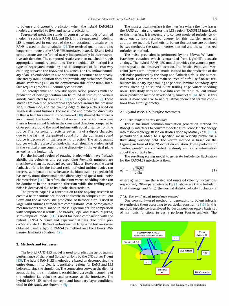
Fig. 1. The hybrid LES/RANS model and boundary layer conditions.
2. Methods and test cases
The hybrid RANS-LES model is used to predict the aerodynamicperformance of sharp and flatback airfoils by the CFD solver Fluent[13]. The hybrid RANS-LES methods are based on decomposing theentire domain into clearly identifiable regions for RANS and LESbefore starting the simulation. The connection between the distinctzones during the simulation is established via explicit coupling ofthe solution, i.e. velocities and pressure, at the interfaces. Thehybrid RANS-LES model concepts and boundary layer conditionsused in this study are shown in Fig. 1.
The most critical interface is the interface where the flow leavesthe RANS domain and enters the LES region (RANS/LES interface).At this interface, it is necessary to convert modeled turbulence ki-netic energy into resolved energy for this transfer using anappropriate method. Synthetic turbulent fluctuations are obtainedby two methods: the random vortex method and the synthesizedturbulence method.
The noise prediction is performed by the Ffowcs WilliamseHawkings equation, which is extended from Lighthill’s acousticanalogy. The hybrid RANS-LES model provides the acoustic pres-sure signal at the observer’s location. The Brooks, Pope, and Mar-colini (BPM) semi-empirical model is used for the prediction of theself-noise produced by the sharp and flatback airfoils. The numer-ical models contain three main sources of airfoil self-noise: tur-bulence boundary layer trailing edge noise, laminar boundary layervortex shedding noise, and blunt trailing edge vortex sheddingnoise. This study does not take into account the turbulent inflownoise predictionmethod developed by Amiet et al. [14] because thisnoise is more sensitive to natural atmospheric and terrain condi-tions than airfoil geometry.
2.1. Hybrid RANS-LES interface treatments
2.1.1. The random vortex methodThis is the most common fluctuation generation method for
RANS/LES interfaces to convert modeled turbulence kinetic energyinto resolved energy. Based on studies done by Mathey et al. [15], aperturbation is added to a specified mean velocity profile via afluctuating vorticity field. The vortex method is based on theLagrangian form of the 2D evolution equation. These particles, or“vortex points”, are converted randomly and carry informationabout the vorticity field.
The resulting scaling model to generate turbulence fluctuationfor the RANS-LES interface is then:
u0*i ¼ u0i
ffiffiffiffiffiffiffiffiffiffiffiffihuiuii
p2=3k
(1)
where u0*i and u0 are the scaled and unscaled velocity fluctuationsrespectively. Other parameters in Eq. (1) above are k, the turbulentkinetic energy; and huiuii, the normal statistic velocity fluctuations.
2.1.2. The synthesized turbulence methodOne commonly-used method for generating turbulent inlets is
to synthesize them according to particular constraints [16]. In thismethod, turbulence is analyzed by decomposition onto a basis setof harmonic functions to easily perform Fourier analysis. The
T. Kim et al. / Renewable Energy 65 (2014) 192e201194
turbulent fluctuations are represented by a linear sum of sine andcosine functions, with coefficients representing the energy con-tained in each mode. The final instantaneous flow profile iscomposed of the mean velocity profile and the generated arbitraryfluctuating profile.
uxðy; tÞ ¼ uxðyÞ þ u0xðy; tÞ ¼ uxðyÞ þ umXNi¼1
a0iðtÞcos�ikyþ 40
iðtÞ�
(2)
here ux is the x-component of the instantaneous velocity, and y is acoordinate across the inlet to the domain. a0iðtÞ and 40
iðtÞ are co-efficients to be determined from some form of a constrainedrandom process. ik is the wave number.
2.2. The Ffowcs Williams and Hawkings equation
For an airfoil, the aerodynamic sound generation by turbulenceand surfaces in arbitrary motion can be predicted by Williams andHawkings equation [12]which is based on Lighthill’s acoustic analogy[17]. This is the rearranged NaviereStokes equation which has theform of an inhomogeneous wave equationwith a quadrupole sourcedistribution in the volume surrounding the body and monopole anddipole sources on thebodysurface. Thedifferential formof theFfowcsWilliamseHawkings (FWeH) equation can be described as:
1c2
v2
vt2p0ð x!; tÞ � V2p0ð x!; tÞ ¼ v
vt½r0vndð f Þ� �
v
vxi½lidð f Þ�
þ v2
vxivxj
�TijHð f Þ
�(3)
where vn is the local velocity of the body in the direction normal tothe surface defined by f ¼ 0, li are the components of the local forceon the surface, and d(f) and H(f) are the Dirac delta and Heavisidefunctions respectively.
The first and second terms in RHS are the monopole source andthe dipole source respectively. Both sources have surface sourcecharacteristics. The third term is a quadrupole source term that actsthroughout the volume that is exterior to the body surface. Themonopole or thickness source term models the noise generated bythe displacement of fluid as the body passes through it. The dipoleor loading source term models the noise that results from the un-steady motion of the force distribution on the body surface. Thequadrupole source term models the non-linearities due to both thelocal sound speed variation and the finite fluid velocity near thebody surface. This source is considerable only in transonic or su-personic conditions. In this study, the prediction of volume noisesource is neglected because thewind turbine blades are operated inthe low Mach number flow field.
The speed and accuracy of the noise calculation is improved byeliminating the time derivative of the first integral in Farassatformulation 1A [18,19]:
p0ð x!; tÞ ¼ p0Tð x!; tÞ þ p0Lð x!; tÞ (4)
where
4pp0T ð x!; tÞ ¼Z
f ¼0
"r0ð _vn þ v _nÞrj1�Mrj2
#ret
dS
þZ
f ¼0
"r0vn
�r _Mr þ cMr � cM2
�r2j1�Mrj3
#ret
dS (5)
4pp0Lð x!; tÞ ¼ 1Z _lr
2 dS
cf ¼0
"rj1�Mrj
#ret
þZ
f ¼0
"lr � lM
rj1�Mr j2#ret
dS
þ 1c
Zf ¼0
"lr�r _Mr þ cMr � cM2
�r2j1�Mrj3
#ret
dS (6)
In this formulation, integrands with 1/r are far-field terms andthose with 1/r2 are near-field terms. A dot over a variable indicatesthe source time derivative of that variable. The subscript n, r and Mrefer to the dot product with the unit normal vector, the unit ra-diation vector, and the surface velocity vector normalized by thespeed of sound, respectively.
2.3. Semi-empirical noise models
2.3.1. Turbulent boundary layer trailing edge noiseThis noise is the most common airfoil self-noise source
especially for high Reynolds number flows. The turbulentboundary layer trailing edge noise is caused by the interactionbetween boundary layer turbulence and the blade’s trailing edge.It has broadband nature and this noise is a primary source ofhigh-frequency noise. The turbulent boundary layer trailingedge noise is modeled as the combination of the pressure sidenoise, the suction side noise and the separation noise by Brookset al. [11]
SPLtotal ¼ 10 log�10SPLp=10 þ 10SPLs=10 þ 10SPLa=10
�(7)
SPLp ¼ 10 log
d*pM
5LDh
r2e
!þ A
StpSt1
þ ðK1 � 3Þ þ DK1 (8)
SPLs ¼ 10 log
d*sM
5LDh
r2e
!þ A
StsSt1
þ ðK1 � 3Þ (9)
SPLa ¼ 10 log
d*sM
5LDh
r2e
!þ BStsSt2
þ K2 (10)
In the above equations, d*p and d*s are the boundary layerdisplacement thickness for the pressure side and suction siderespectively. Other parameters in Eqs. (8)e(10) are M, the Machnumber; L, the airfoil span length; re, the effective observer dis-tance; A and B, the empirical spectral shape functions based on theStrouhal number; K1 and K2, the amplitude functions based on a*,the effective aerodynamic angle of attack, and Rec, the Reynoldsnumber based on the chord length; and Dh is the directivity func-tion for high-frequency noise.
2.3.2. Blunt trailing edge vortex shedding noiseThis noise is caused by vortex sheddings from the blunt trailing
edge. The efficient tonal noise is radiated from the trailing edge. Thesharpening of the trailing edge will shift the noise peak towards theultrasound region. However, the flatback airfoil inherently pos-sesses blunt trailing edge noise sources because of the thick trailingedge. The blunt trailing edge vortex shedding noise is described as:
T. Kim et al. / Renewable Energy 65 (2014) 192e201 195
SPLblunt ¼ 10 log
hM5:5DLDh
!þ G4@ h
;JA
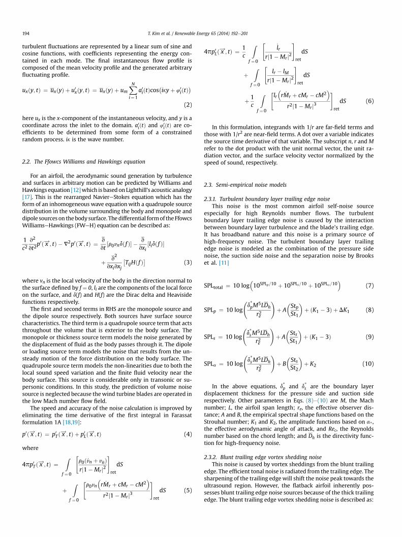
Fig. 3. Close-up view of the mesh near the DU97-flatback airfoil trailing edge.
r2
0d*avg
1
þ G5
0@ h
d*avg;J;
St000
St000peak
1A (11)
where h is the trailing edge thickness and d*avg is the averageboundary layer displacement thickness for pressure and suctionsides of the flatback airfoil. J is the solid angle, in degree, betweenthe sloping surfaces upstream of the trailing edge. G4 is the functionto determine the peak level of the spectrum and G5 is the functionto define the shape of the spectrum. St000 is the Strouhal number,defined as St000 ¼ fh=U. Dh is the high frequency directivity functiondefined as:
DhðQe;FeÞz 2 sin2ðQe=2Þsin2Fe
ð1þM cos QeÞ½1þ ðM �MeÞcos Qe�2(12)
where the overbar on Dh indicates that it is normalized by thetrailing edge noise radiated normal to the streamwise axisðQe ¼ 90�Þ and the flyover plane ðFe ¼ 90�Þ direction.
2.4. Test cases and computational conditions
The test flatback airfoils are categorized into two groups. The firstairfoil group is composed of DU97-W-300 andDU97-flatback airfoils,which is tested for aeroacoustic characteristics. The second airfoilgroup contains KWA029-400 which is based on the DU00-W2-401airfoil. This airfoil is tested for the similarities and differences inaerodynamic performance between different numerical approachesand experiments. The numerical approaches are the XFOIL panelmethod, RANS, LES, and hybrid RANS-LES methods.
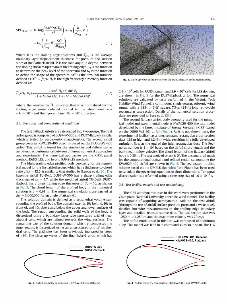
The blunt trailing edge profiled body geometry for the numer-ical model for the first airfoil group, which has a thickness-to-chordratio of t/c¼ 12.5, is similar to that studied by Barone et al. [20]. Thebaseline airfoil TU-Delft DU97-W-300 has a sharp trailing edgethickness of t/c ¼ 1.7, while the modified airfoil TU-Delft DU97-flatback has a blunt trailing edge thickness of t/c ¼ 10, as shownin Fig. 2. The chord length of the profiled body in the numericalsolution is c ¼ 0.91 m. The numerical simulations are carried atRec ¼ 3,000,000 for an angle of attack 4�.
The solution domain is defined as a tetrahedral volume sur-rounding the profiled body. The domain extends 10c behind, 10c infront of, and 10c above and below the upper and lower surfaces ofthe body. The region surrounding the solid walls of the body isdiscretized using a boundary layer-type structured grid of hex-ahedral cells, which are refined towards the wing surfaces. Theremaining part of the solution domain, which encompasses theinner region, is discretized using an unstructured grid of tetrahe-dral cells. The grid size has been previously increased in stepsof þ9%. The close up views of the final hybrid grids, which has
Fig. 2. Airfoil geometry comparison (DU97-W-300 and flatback).
2.9 � 105 cells for RANS domain and 3.9 � 106 cells for LES domain,are shown in Fig. 3 for the DU97-flatback airfoil. The numericalsolutions are validated by tests performed in the Virginia TechStability Wind Tunnel, a continuous, single-return, subsonic windtunnel with a 1.83-m (6-ft) square, 7.3-m (24-ft) long removablerectangular test section. Details of the numerical solution proce-dure are provided in Berg et al. [21].
The second flatback airfoil body geometry used for the numer-ical model and experimental model is KWA029-400, the test modeldeveloped by the Korea Institute of Energy Research (KIER) basedon the DU00-W2-401 airfoil (Fig. 4). As it is not shown here, theexperimental facility has a long, constant rectangular cross-sectionduct 1.25 m high and 1.249 m wide, resulting in a fully-developedturbulent flow at the end of the inlet rectangular duct. The Rey-nolds number is 1 � 106 based on the airfoil chord length and thebulk-mean inflow velocity. The chord length of the flatback airfoilbody is 0.35m. The test angle of attack is 0�. The unstructuredmeshfor the computational domain and refined region surrounding theKWA029-400 airfoil are shown in Fig. 5. The segregated implicitscheme based on the SIMPLE algorithm from Fluent has been usedto calculate the governing equations in three dimensions. Temporaldiscretization is performed using a time step size of 1.0 � 10�5 s.
2.5. Test facility, models and test methodology
The KIER aerodynamic tests in this work were performed in theChungnam National University anechoic wind tunnel. The facilitywas capable of acquiring aerodynamic loads on the test airfoil(through the use of airfoil surface pressure ports and a wake rake),detailed hot-wire measurements in the trailing edge boundarylayer and detailed acoustic source data. The test section size was1.250 m � 1.250 m and the maximum velocity was 70 m/s.
The airfoil model used in this test was composed of aluminumalloy. This model was 0.35 m in chord and 1.249 m in span. The 11%
Fig. 4. Airfoil geometry comparison (DU00-W2-401 and KWA029-400).
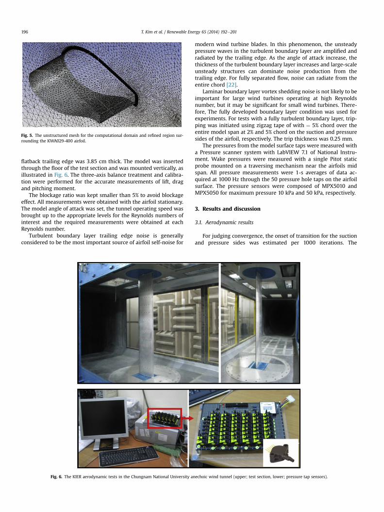
Fig. 5. The unstructured mesh for the computational domain and refined region sur-rounding the KWA029-400 airfoil.
T. Kim et al. / Renewable Energy 65 (2014) 192e201196
flatback trailing edge was 3.85 cm thick. The model was insertedthrough the floor of the test section and was mounted vertically, asillustrated in Fig. 6. The three-axis balance treatment and calibra-tion were performed for the accurate measurements of lift, dragand pitching moment.
The blockage ratio was kept smaller than 5% to avoid blockageeffect. All measurements were obtained with the airfoil stationary.The model angle of attack was set, the tunnel operating speed wasbrought up to the appropriate levels for the Reynolds numbers ofinterest and the required measurements were obtained at eachReynolds number.
Turbulent boundary layer trailing edge noise is generallyconsidered to be the most important source of airfoil self-noise for
Fig. 6. The KIER aerodynamic tests in the Chungnam National University an
modern wind turbine blades. In this phenomenon, the unsteadypressure waves in the turbulent boundary layer are amplified andradiated by the trailing edge. As the angle of attack increase, thethickness of the turbulent boundary layer increases and large-scaleunsteady structures can dominate noise production from thetrailing edge. For fully separated flow, noise can radiate from theentire chord [22].
Laminar boundary layer vortex shedding noise is not likely to beimportant for large wind turbines operating at high Reynoldsnumber, but it may be significant for small wind turbines. There-fore, The fully developed boundary layer condition was used forexperiments. For tests with a fully turbulent boundary layer, trip-ping was initiated using zigzag tape of with ¼ 5% chord over theentire model span at 2% and 5% chord on the suction and pressuresides of the airfoil, respectively. The trip thickness was 0.25 mm.
The pressures from the model surface taps were measured witha Pressure scanner system with LabVIEW 7.1 of National Instru-ment. Wake pressures were measured with a single Pitot staticprobe mounted on a traversing mechanism near the airfoils midspan. All pressure measurements were 1-s averages of data ac-quired at 1000 Hz through the 50 pressure hole taps on the airfoilsurface. The pressure sensors were composed of MPX5010 andMPX5050 for maximum pressure 10 kPa and 50 kPa, respectively.
3. Results and discussion
3.1. Aerodynamic results
For judging convergence, the onset of transition for the suctionand pressure sides was estimated per 1000 iterations. The
echoic wind tunnel (upper; test section, lower; pressure tap sensors).
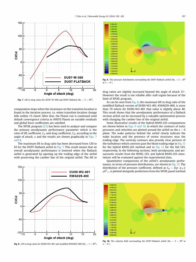
Fig. 7. Lift to drag ratios for DU97-W-300 and DU97-flatback (Rec ¼ 3 � 106).
Fig. 9. The pressure distribution surrounding the DU97-flatback airfoil (Rec ¼ 3 � 106
at a ¼ 4�).
T. Kim et al. / Renewable Energy 65 (2014) 192e201 197
computation stops when the invariance on the transition location isfound in the iterative process, i.e. when transition location changefalls within 1% chord. After that, the Fluent run is continued untildefault convergence criteria in ANSYS Fluent on variable residualsand global force coefficients are satisfied.
The XFOIL program [23] has been used to analyze and comparethe primary aerodynamic performance parameter which is theratio of lift coefficient, CL, and drag coefficient, CD, according to theangle of attack, a and the results are shown graphically in Figs. 7and 8.
The maximum lift to drag ratio has been decreased from 120 to65 for the DU97-flatback airfoil in Fig. 7. This result means that anoverall aerodynamic performance is lowered when the flatbackairfoil is generated by opening up the trailing edge of the airfoilwith preserving the camber line of the original airfoil. The lift to
Fig. 8. Lift to drag ratios for DU00-W2-401 and modified KWA029-400 (Rec ¼ 1 �106).
drag ratios are slightly increased beyond the angle of attack 13�.However the result is not reliable after stall region because of thelimit of XFOIL program.
As can be seen from Fig. 8, the maximum lift to drag ratio of themodified flatback version of DU00-W2-401, KWA029-400, is morethan 70 where for DU00-W2-401 that value is slightly above 40.This result shows that the aerodynamic performance of a flatbackversion airfoil can be increased by a valuable optimization processwith changing the camber line of the original airfoil.
Some illustrative results of the hybrid RANS-LES computationsare shown below in Figs. 9 and 10, in which the contours of staticpressures and velocities are plotted around the airfoil on the z ¼ 0plane. The wake patterns behind the airfoil clearly indicate thewake location and the presence of vortex structures near thetrailing edge. The vorticity contours also provide clear pictures ofthe turbulence which convects past the blunt trailing edge in Fig. 11for the hybrid RANS-LES method and in Fig. 12 for the full LES,respectively. In the following sections, both aerodynamic and aer-oacoustic results from the RANS, LES, and hybrid RANS-LES simu-lations will be evaluated against the experimental data.
Quantitative comparisons of the airfoil’s aerodynamic perfor-mance, in terms of pressure distributions, are shown in Fig. 13. Thedistribution of the pressure coefficient, defined as Cp ¼ 2(p�pN)/rU2
N, is plotted alongside predictions from the XFOIL panel method
Fig. 10. The velocity field surrounding the DU97-flatback airfoil (Rec ¼ 3 � 106 ata ¼ 4�).
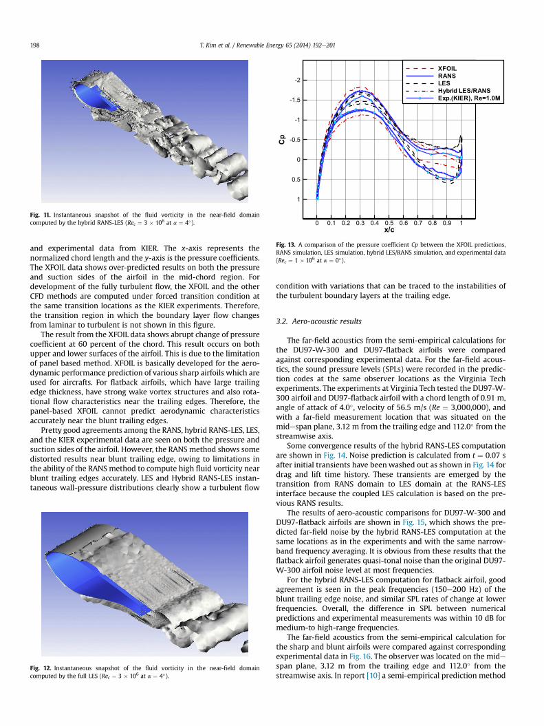
Fig. 11. Instantaneous snapshot of the fluid vorticity in the near-field domaincomputed by the hybrid RANS-LES (Rec ¼ 3 � 106 at a ¼ 4�).
x/c
Cp
0 0.1 0.2 0.3 0.4 0.5 0.6 0.7 0.8 0.9 1
-2
-1.5
-1
-0.5
0
0.5
1
XFOIL
RANS
LES
Hybrid LES/RANS
Exp.(KIER), Re=1.0M
Fig. 13. A comparison of the pressure coefficient Cp between the XFOIL predictions,RANS simulation, LES simulation, hybrid LES/RANS simulation, and experimental data(Rec ¼ 1 � 106 at a ¼ 0�).
T. Kim et al. / Renewable Energy 65 (2014) 192e201198
and experimental data from KIER. The x-axis represents thenormalized chord length and the y-axis is the pressure coefficients.The XFOIL data shows over-predicted results on both the pressureand suction sides of the airfoil in the mid-chord region. Fordevelopment of the fully turbulent flow, the XFOIL and the otherCFD methods are computed under forced transition condition atthe same transition locations as the KIER experiments. Therefore,the transition region in which the boundary layer flow changesfrom laminar to turbulent is not shown in this figure.
The result from the XFOIL data shows abrupt change of pressurecoefficient at 60 percent of the chord. This result occurs on bothupper and lower surfaces of the airfoil. This is due to the limitationof panel based method. XFOIL is basically developed for the aero-dynamic performance prediction of various sharp airfoils which areused for aircrafts. For flatback airfoils, which have large trailingedge thickness, have strong wake vortex structures and also rota-tional flow characteristics near the trailing edges. Therefore, thepanel-based XFOIL cannot predict aerodynamic characteristicsaccurately near the blunt trailing edges.
Pretty good agreements among the RANS, hybrid RANS-LES, LES,and the KIER experimental data are seen on both the pressure andsuction sides of the airfoil. However, the RANSmethod shows somedistorted results near blunt trailing edge, owing to limitations inthe ability of the RANS method to compute high fluid vorticity nearblunt trailing edges accurately. LES and Hybrid RANS-LES instan-taneous wall-pressure distributions clearly show a turbulent flow
Fig. 12. Instantaneous snapshot of the fluid vorticity in the near-field domaincomputed by the full LES (Rec ¼ 3 � 106 at a ¼ 4�).
condition with variations that can be traced to the instabilities ofthe turbulent boundary layers at the trailing edge.
3.2. Aero-acoustic results
The far-field acoustics from the semi-empirical calculations forthe DU97-W-300 and DU97-flatback airfoils were comparedagainst corresponding experimental data. For the far-field acous-tics, the sound pressure levels (SPLs) were recorded in the predic-tion codes at the same observer locations as the Virginia Techexperiments. The experiments at Virginia Tech tested the DU97-W-300 airfoil and DU97-flatback airfoil with a chord length of 0.91 m,angle of attack of 4.0�, velocity of 56.5 m/s (Re ¼ 3,000,000), andwith a far-field measurement location that was situated on themidespan plane, 3.12 m from the trailing edge and 112.0� from thestreamwise axis.
Some convergence results of the hybrid RANS-LES computationare shown in Fig. 14. Noise prediction is calculated from t ¼ 0.07 safter initial transients have beenwashed out as shown in Fig. 14 fordrag and lift time history. These transients are emerged by thetransition from RANS domain to LES domain at the RANS-LESinterface because the coupled LES calculation is based on the pre-vious RANS results.
The results of aero-acoustic comparisons for DU97-W-300 andDU97-flatback airfoils are shown in Fig. 15, which shows the pre-dicted far-field noise by the hybrid RANS-LES computation at thesame locations as in the experiments and with the same narrow-band frequency averaging. It is obvious from these results that theflatback airfoil generates quasi-tonal noise than the original DU97-W-300 airfoil noise level at most frequencies.
For the hybrid RANS-LES computation for flatback airfoil, goodagreement is seen in the peak frequencies (150e200 Hz) of theblunt trailing edge noise, and similar SPL rates of change at lowerfrequencies. Overall, the difference in SPL between numericalpredictions and experimental measurements was within 10 dB formedium-to high-range frequencies.
The far-field acoustics from the semi-empirical calculation forthe sharp and blunt airfoils were compared against correspondingexperimental data in Fig. 16. The observer was located on the midespan plane, 3.12 m from the trailing edge and 112.0� from thestreamwise axis. In report [10] a semi-empirical prediction method
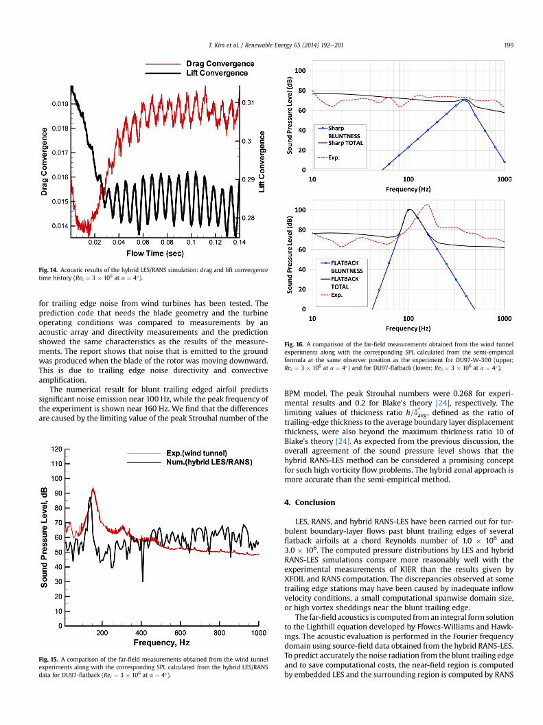
Fig. 14. Acoustic results of the hybrid LES/RANS simulation: drag and lift convergencetime history (Rec ¼ 3 � 106 at a ¼ 4�).
Fig. 16. A comparison of the far-field measurements obtained from the wind tunnelexperiments along with the corresponding SPL calculated from the semi-empiricalformula at the same observer position as the experiment for DU97-W-300 (upper;Rec ¼ 3 � 106 at a ¼ 4�) and for DU97-flatback (lower; Rec ¼ 3 � 106 at a ¼ 4�).
T. Kim et al. / Renewable Energy 65 (2014) 192e201 199
for trailing edge noise from wind turbines has been tested. Theprediction code that needs the blade geometry and the turbineoperating conditions was compared to measurements by anacoustic array and directivity measurements and the predictionshowed the same characteristics as the results of the measure-ments. The report shows that noise that is emitted to the groundwas produced when the blade of the rotor was moving downward.This is due to trailing edge noise directivity and convectiveamplification.
The numerical result for blunt trailing edged airfoil predictssignificant noise emission near 100 Hz, while the peak frequency ofthe experiment is shown near 160 Hz. We find that the differencesare caused by the limiting value of the peak Strouhal number of the
Fig. 15. A comparison of the far-field measurements obtained from the wind tunnelexperiments along with the corresponding SPL calculated from the hybrid LES/RANSdata for DU97-flatback (Rec ¼ 3 � 106 at a ¼ 4�).
BPM model. The peak Strouhal numbers were 0.268 for experi-mental results and 0.2 for Blake’s theory [24], respectively. Thelimiting values of thickness ratio h=d*avg, defined as the ratio oftrailing-edge thickness to the average boundary layer displacementthickness, were also beyond the maximum thickness ratio 10 ofBlake’s theory [24]. As expected from the previous discussion, theoverall agreement of the sound pressure level shows that thehybrid RANS-LES method can be considered a promising conceptfor such high vorticity flow problems. The hybrid zonal approach ismore accurate than the semi-empirical method.
4. Conclusion
LES, RANS, and hybrid RANS-LES have been carried out for tur-bulent boundary-layer flows past blunt trailing edges of severalflatback airfoils at a chord Reynolds number of 1.0 � 106 and3.0 � 106. The computed pressure distributions by LES and hybridRANS-LES simulations compare more reasonably well with theexperimental measurements of KIER than the results given byXFOIL and RANS computation. The discrepancies observed at sometrailing edge stations may have been caused by inadequate inflowvelocity conditions, a small computational spanwise domain size,or high vortex sheddings near the blunt trailing edge.
The far-field acoustics is computed froman integral formsolutionto the Lighthill equation developed by Ffowcs-Williams and Hawk-ings. The acoustic evaluation is performed in the Fourier frequencydomain using source-field data obtained from the hybrid RANS-LES.To predict accurately the noise radiation from the blunt trailing edgeand to save computational costs, the near-field region is computedby embedded LES and the surrounding region is computed by RANS
T. Kim et al. / Renewable Energy 65 (2014) 192e201200
simultaneously. The space-time characteristics of surface pressurefluctuations are obtained to provide the acoustic source functions forthe far-field noise calculation. The frequency spectra of surfacepressure fluctuations obtained from the hybrid RANS-LES agreewellwith experimental measurements at the same observer location.
The present hybrid RANS-LES method is found to be adequatefor predicting noise radiation over a range of frequencies comparedto the BPM semi-empirical method. At the peak frequency and peaklevel of blunt trailing edge vortex shedding noise, however, theestimation based on surface pressure fluctuations does not pre-cisely match the experimental measurements. This issue will beaddressed in future simulations using an expanded computationaldomain and improved inflow velocity conditions.
Acknowledgment
This work was supported by the Human Resources Develop-ment Program (No. 20124030200030) and the New & RenewableEnergy Technology Development Program (No. 20123010020130)of the Korea Institute of Energy Technology Evaluation and Plan-ning (KETEP) grant funded by the Korea Government Ministry ofTrade, Industry and Energy.
Nomenclature
AbbreviationsBPM Brooks, Pope, and MarcoliniCFD computational fluid dynamicsLES large eddy simulationSGS subgrid scaleSIMPLE semi-implicit method for pressure-linked equationsSPL sound pressure levelSST shear stress transportRANS Reynolds-averaged NaviereStokes2D two-dimensional
Upper-case romanCp pressure coefficientDh high frequency directivity functionE spectral distribution of turbulent energyF switch mechanism functionG4 function to determine the peak level of the spectrumG5 function to define the shape of the spectrumH Heaviside functionG!
Source source vectorG!
Trans transport vectorM Mach numberRe Reynolds numberSt000 Strouhal number defined as St000 ¼ fh=UU mean velocity
Lower-case romanc chord lengthf defined surface, frequencyh trailing edge thicknessi number of grid-lineik wavenumberk turbulent kinetic energyl wavelength of the energy modeli component of local force on the surfacep pressurep0 pressure fluctuationp0T pressure fluctuation for thickness noisep0 pressure fluctuation for loading noise
r distancet timeux x-component of the instantaneous velocityu, v, w velocity componentsvn local normal velocity of the bodyx, y, z Cartesian coordinates
Upper-case GreekQe angle from source streamwise axis x to observerFe angle from source lateral axis y to observerJ solid angleU vorticity magnitude
Lower-case Greekd Dirac delta functiond*avg average boundary layer displacement thicknessε turbulent dissipation rateh Kolmogorov scalek wave number of Fourier energy moden eddy viscosityr densityu turbulent kinetic energy
Symbols and indicesMn dot product with the unit normal vectorMr dot product with the unit radiation vector_M source time derivativeu0*i scaled fluctuation u0 unscaled fluctuationhuiuii normal statistic fluctuationf0iðtÞ coefficient of a constrained random process
References
[1] Ashwill T, Laird D. Concepts to facilitate very large blades. In: Proceedings ofASME/AIAA wind energy symposium 2007. Reno, NV.
[2] Oertel Jr H. Wakes behind blunt bodies. Ann Rev Fluid Mech 1990;22:539e64.[3] Davidson L, Peng SH. Hybrid LES-RANS modeling: a one-equation SGS model
combined with a k-u model for predicting recirculating flows. InternationalJournal for Numerical Methods in Fluids 2003;43:1003e18.
[4] Hanjalic K, Hadzabdic M, Temmerman L, Leschziner M. Merging LES and RANSstrategies: zonal or seamless coupling? Direct Large Eddy Simul V 2004;5:451e64.
[5] Temmerman L, Hadzabdic M, Leschziner M, Hanjalic K. A hybrid two-layerURANS-LES approach for large eddy simulation at high Reynolds numbers.Int J Heat Fluid Flow 2005;26:173e90.
[6] Abe K, Ohtsuka T. An investigation of LES and hybrid RANS-LES models forpredicting 3-D diffuser flow. International Journal of Heat and Fluid Flow2010;31:833e44.
[7] Fröhlich J, von Terzi D. Hybrid RANS-LES methods for the simulation of tur-bulent flows. Prog Aero Sci 2008;44:349e77.
[8] Kim T, Lee S, Kim H, Lee S. Design of low noise airfoil with high aerodynamicperformance for use on small wind turbines. Sci China 2010;53:75e9.
[9] Göçmen T, Özerdem B. Airfoil optimization for noise emission problem andaerodynamic performance criterion on small scale wind turbines. Energy2012;46:62e71.
[10] Oerlemans S, Sijtsma P, Mendez López B. Location and quantification of noisesources on a wind turbine. J Sound Vib 2007;299:869e83.
[11] Brooks TF, Pope DS, Marcolini MA. Airfoil self-noise and prediction. NASAReference Publication 1218; 1989.
[12] Ffowcs Williams JE, Hawkings DL. Sound generated by turbulence and sur-faces in arbitrary motion. Philosophical Transactions of the Royal Society A:Mathematical, Physical & Engineering Sciences 1969;264(1151):321e42.
[13] ANSYS FLUENT 13.0 documentation. ANSYS, Inc.[14] Amiet RK. Acoustic radiation from an airfoil in a turbulent stream. J Sound Vib
1975;41(4):407e20.[15] Mathey F, Coklijat D, Bertoglio JP, Sergent E. Specification of LES inlet
boundary condition using vortex method. In: 4th international symposium onturbulence, heat and mass transfer. Antalya, Turkey: Begell House; 2003.
[16] Tabor GR, Baba-Ahmadi MH. Inlet conditions for large eddy simulation: areview. Comput Fluids 2010;39:553e67.
[17] Lighthill MJ. On sound generated aerodynamically. I: general theory. Pro-ceedings of the Royal Society A 1952;211:564e87.
[18] Farassat F, Succi GP. The prediction of helicopter discrete frequency noise.Vertica 1983;7(4):309e20.

T. Kim et al. / Renewable Energy 65 (2014) 192e201 201
[19] Brentner KS. Prediction of helicopter discrete frequency rotor noise-a com-puter program incorporating realistic blade motions and advanced acousticformulation. NASA; October 1986. TM 87721.
[20] BaroneM,Paquette J.Aeroacoustics andaerodynamicperformanceof a rotorwithflatback airfoils. In: European wind energy conference 2010. Warsaw, Poland.
[21] BergDE, Zayas JR.Aerodynamicandaeroacousticpropertiesofflatbackairfoils. In:46th AIAA aerospace sciences meeting and exhibit January 2008. Reno, Nevada.
[22] Migliore P, Oerlemans S. Wind tunnel aeroacoustic tests of six airfoils for useon small wind turbines; 2003. NREL/CP-5e35090.
[23] Drela M. XFOIL: an analysis and design system for low Reynolds numberairfoils. In: Mueller TJ, editor. Low Reynolds number aerodynamics, lecturenotes in engineering. New York: Springer; 1989. p. 54e61.
[24] Blake WK. Mechanics of flow-induced sound and vibration. Orlando, Florida,USA: Academic Press, Inc; 1986.


![Effect of Gurney Flap on Airfoil Lift Coefficient by Design of …jast.modares.ac.ir/article-15-20880-fa.pdf · of Gurney flap on SFYT15thick airfoil [19] Aerodynamic efficiency study](https://static.fdocuments.in/doc/165x107/60bd5a358e42e2274f7a1aaf/effect-of-gurney-flap-on-airfoil-lift-coefficient-by-design-of-jast-of-gurney-flap.jpg)