Numerical simulation of ballistic impacts on ceramic material · · 2008-09-19Summary Within PDE...
74
Numerical simulation of ballistic impacts on ceramic material A.P.T.M.J. Lamberts MT07.33 Committee: prof. dr. ir. M.G.D. Geers dr. ir. J.A.W. van Dommelen dr. ir. H.C. de Lange ir. A.T.M.J.M. Huizinga Eindhoven University of Technology Department of Mechanical Engineering Materials Technology PDE Automotive B.V. Computer Aided Engineering Eindhoven, August 22 nd , 2007
Transcript of Numerical simulation of ballistic impacts on ceramic material · · 2008-09-19Summary Within PDE...

Numerical simulation of ballisticimpacts on ceramic material
A.P.T.M.J. LambertsMT07.33
Committee:
prof. dr. ir. M.G.D. Geersdr. ir. J.A.W. van Dommelendr. ir. H.C. de Langeir. A.T.M.J.M. Huizinga
Eindhoven University of TechnologyDepartment of Mechanical EngineeringMaterials Technology
PDE Automotive B.V.Computer Aided Engineering
Eindhoven, August 22nd, 2007


Contents
Samenvatting IV
Summary VI
1 Introduction 1
2 State of the art: ceramic armouring 3
2.1 Ceramic material . . . . . . . . . . . . . . . . . . . . . . . . . . . . . . . 3
2.2 Ceramic armour . . . . . . . . . . . . . . . . . . . . . . . . . . . . . . . 6
2.3 Bullets . . . . . . . . . . . . . . . . . . . . . . . . . . . . . . . . . . . . . 9
3 Material characterisation 13
3.1 Plate impact experiments . . . . . . . . . . . . . . . . . . . . . . . . . . 13
3.2 Bar impact experiments . . . . . . . . . . . . . . . . . . . . . . . . . . . 14
3.3 Penetration experiments . . . . . . . . . . . . . . . . . . . . . . . . . . . 15
4 Bullet impact experiments 17
5 Material modelling 21
5.1 Simha model . . . . . . . . . . . . . . . . . . . . . . . . . . . . . . . . . 21
5.2 Johnson–Holmquist ceramic models . . . . . . . . . . . . . . . . . . . . . 22
5.3 Microphysical models . . . . . . . . . . . . . . . . . . . . . . . . . . . . . 23
I

II CONTENTS
5.4 Material model selection . . . . . . . . . . . . . . . . . . . . . . . . . . . 24
5.5 Johnson–Holmquist–Beissel model . . . . . . . . . . . . . . . . . . . . . 25
5.6 Material models for metals . . . . . . . . . . . . . . . . . . . . . . . . . 28
6 MSC.Dytran code 31
7 Model validation 35
7.1 Plate impact . . . . . . . . . . . . . . . . . . . . . . . . . . . . . . . . . 36
7.2 Thick target impact . . . . . . . . . . . . . . . . . . . . . . . . . . . . . 38
8 Numerical issues in MSC.Dytran 43
8.1 Voids . . . . . . . . . . . . . . . . . . . . . . . . . . . . . . . . . . . . . . 44
8.2 Bullet impact fitting . . . . . . . . . . . . . . . . . . . . . . . . . . . . . 47
8.3 Depth of penetration . . . . . . . . . . . . . . . . . . . . . . . . . . . . . 48
9 Conclusion and recommendations 53
9.1 Conclusion . . . . . . . . . . . . . . . . . . . . . . . . . . . . . . . . . . 53
9.2 Recommendations . . . . . . . . . . . . . . . . . . . . . . . . . . . . . . 54
Bibliography 59
Acknowledgement 61
A Experimental results 63
B Additional pressure 65
Samenvatting
Binnen PDE Automotive, onderdeel van de Benteler Automotive Company, is eenspeciale divisie die zich bezig houdt met het ontwikkelen en bouwen van gepantserdevoertuigen. Hiervoor wordt een zelf ontwikkeld pantserstaal gebruikt. Om hetballistisch beschermingsniveau te verhogen, is het toepassen van eenvoudigwegdikkere staalplaten geen optie vanwege een te hoge toename van het voertuiggewicht.Keramische tegels daarentegen bieden het voordeel een lagere dichtheid te hebben,maar toch zeer hard te zijn. Door deze tegels op pantserstaalplaten te lijmen, kaneenzelfde of zelfs hogere beschermingsgraad verkregen worden met een lager gewichtper oppervlakte eenheid, in vergelijking tot het gebruik van pantserstaal alleen. Omte voorspellen wat er gebeurt als een kogel een keramiek/pantserstaal doel treft, wilPDE Automotive gebruik gaan maken van eindige elementen analyses. In het eindigeelementen programma MSC.Dytran, dat binnen PDE wordt gebruikt voor ballistischesimulaties uit te voeren, is echter geen geschikt keramiek model aanwezig. Het doelvan deze afstudeeropdracht is dan ook, om een geschikt keramisch materiaal model teimplementeren, dit vervolgens te valideren en uiteindelijk keramisch pantsermateriaalte simuleren.
Uit een literatuurstudie kwam naar voren, dat het Johnson–Holmquist–Beisselmodel (JHB) het meest geschikt was om het gedrag van keramisch materiaal tebeschrijven. Daar keramisch materiaal ook nog enige sterkte onder compressie bezitnadat het gefaald is, werden de intacte en gefaalde materiaal sterktes door tweeafzonderlijke vergelijkingen beschreven. Een schade parameter bepaalde wanneerwelke vergelijking gebruik dient te worden. Daarnaast was ook een specifiek modelaanwezig om de hydrostatische druk–volume respons te beschrijven. Met behulp vanuser–subroutines, werd het JHB model in MSC.Dytran geımplementeerd.
Om de implementatie van het JHB model te valideren, werden zogeheten plate
III

IV CONTENTS
impact simulaties uitgevoerd. Een keramische plaat werd op een andere keramischegeschoten, waardoor een schokgolf gegenereerd werd in beide platen. De resultatenverkregen uit deze simulaties toonden een goede overeenkomst met experimenteleresultaten, verkregen uit de literatuur. Daarnaast werden ook thick target impactsimulaties uitgevoerd, waarin een lange staaf werd afgevuurd op een dik blok keramiek.De gegenereerde resultaten vertoonden wederom grote gelijkenis met experimentelewaarden. Ook het karakteristieke schadeverloop in het keramiek, zoals radiale scheur-groei en het ontstaan van een schadeconus in het gebied voor het projectiel, wasduidelijk zichtbaar. Tijdens deze simulaties, kwam ook een beperking naar voren vanhet gebruik van een Euler gebaseerde aanpak. Materiaal dat met elkaar in contactstaat, maar geen enkele binding met elkaar heeft, kan niet correct gemodelleerdworden in MSC.Dytran bij gebruik van de Euler methode, omdat materiaal metsamenvallende oppervlaktes geacht wordt aan elkaar vast te zitten.
Tijdens simulaties van kogelinslagen op pantserstaalplaten, om nieuwe materiaalparameters voor het pantserstaal te verkrijgen, bleek dat MSC.Dytran onjuisteresultaten genereerde. Bij gebruik van de axiaal symmetrie optie traden onjuiste voidfractie berekeningen op. Dit resulteerde in onverwacht materiaal falen. Daarnaast washet niet mogelijk een eenduidige materiaal parameterset aan te wijzen. Resultatenvan depth of penetration simulaties, uitgevoerd in MSC.Dytran met gebruik van hetJohnson–Cook model, vertoonden significante verschilllen met resultaten uit andereeindige elementen programma’s. Na onderzoek werden twee onjuistheden gevonden.Het opnieuw uitvoeren van de berekeningen met de aangepaste programmatuurresulteerde echter niet in betere resultaten.
Voor model validatie of voor het verkrijgen van keramische material parame-ters, werden ballistische experimenten op keramiek/pantserstaal doelen uitgevoerd.Vanwege het feit dat het staal niet correct kon worden gemodelleerd, was het echterniet mogelijk deze experimenten te simuleren.

Summary
Within PDE Automotive, a part of the Benteler Automotive Company, armoured pas-senger cars are developed and built with in house developed specialised armour steel.To improve the ballistic protection level, ceramic tiles are used as add–on armour. Theadvantage of using ceramic material instead of simply adding more armoured steel,is the fact that it is less dense but still providing excellent armouring capabilities.Therefore an equal or even higher ballistic performance can be achieved with a notablyreduced weight per area. To predict the impact of various projectiles on the ce-ramic/steel armouring, PDE Automotive wants to use finite element analyses. Withinthe FE–code MSC.Dytran, which is used by PDE for ballistic simulations, a ceramicmaterial model was not available. Therefore this thesis objective was to implement asuitable ceramic material model and to validate and simulate ceramic armour material.
A literature study learnt that the Johnson–Holmquist–Beissel model (JHB) wasto be the most suitable for describing the response of ceramic material. As ceramicmaterial remains to have some compressive strength after failure, this model describedthe intact and failed material strength by two separate analytic expressions, bothbeing strain rate dependent. A damage parameter distinguished between the intactand failed response. Furthermore, a specific model was used for the hydrostaticresponse. By use of user–subroutines, this model has been implemented into theMSC.Dytran code.
To validate the JHB model implementation, plate impact simulations on siliconcarbide have been performed. In this simulation a ceramic plate was impacted byanother ceramic plate, creating a shock wave in both disks. By using laser, thematerial velocity at the back of the impacted plate was measured during experiments.The generated results were in good agreement with experimental results, obtainedfrom literature. Next to this, thick target impact simulations, where a thick ceramic
V
VI CONTENTS
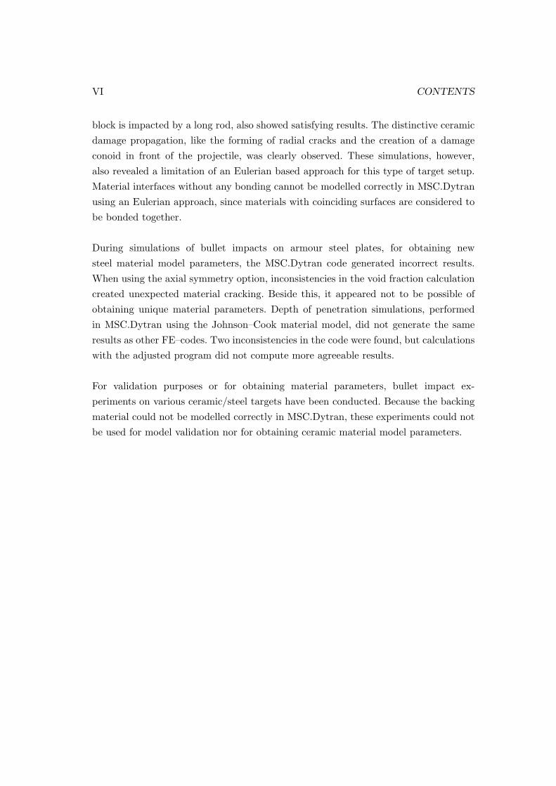
block is impacted by a long rod, also showed satisfying results. The distinctive ceramicdamage propagation, like the forming of radial cracks and the creation of a damageconoid in front of the projectile, was clearly observed. These simulations, however,also revealed a limitation of an Eulerian based approach for this type of target setup.Material interfaces without any bonding cannot be modelled correctly in MSC.Dytranusing an Eulerian approach, since materials with coinciding surfaces are considered tobe bonded together.
During simulations of bullet impacts on armour steel plates, for obtaining newsteel material model parameters, the MSC.Dytran code generated incorrect results.When using the axial symmetry option, inconsistencies in the void fraction calculationcreated unexpected material cracking. Beside this, it appeared not to be possible ofobtaining unique material parameters. Depth of penetration simulations, performedin MSC.Dytran using the Johnson–Cook material model, did not generate the sameresults as other FE–codes. Two inconsistencies in the code were found, but calculationswith the adjusted program did not compute more agreeable results.
For validation purposes or for obtaining material parameters, bullet impact ex-periments on various ceramic/steel targets have been conducted. Because the backingmaterial could not be modelled correctly in MSC.Dytran, these experiments could notbe used for model validation nor for obtaining ceramic material model parameters.

Chapter 1
Introduction
Wars, criminal activities and violence have always been part of our society since thebeginning of mankind. Thereby all kinds of weapons are used to harm the opponent.Because of this, there has always been the need for protection against these attacks.Throughout the centuries, weapons have been improved to be able to attack from alarger distance, to improve the accuracy of attacks and to increase injury capabilities.In return, armouring techniques needed to be upgraded to follow these developmentsin order to withstand the increasing impact forces. Today, specialised armoured steelis used to provide adequate protection against bullet impacts. Police and militarypersonnel are equipped with lightweight armour vests made of Kevlar or ceramics. Butnot only police or military forces are faced with the danger of being attacked by use offire arms. For example representatives of governments, public figures or UN employeeshave to be protected from being assaulted by activists or terrorist groups as well. Thisneed for armoured protection is still increasing, since these acts of violence are notconstrained by any country borders. Car manufacturers and companies, specialised inballistic protection, anticipate to this by providing the necessary armour protection.
One of these suppliers is PDE Automotive, which is part of the Benteler Auto-motive Company, where armoured passenger cars are being developed and builtwith specialised armour steel developed in house. Since many types of bullets exist,they are categorised into classes by their ballistic impact severity. Armoured vehiclestherefore have to be specifically certified according to the class they need to complyto. The experiments required as well as the certification itself are rather expensive.The development of these products can be facilitated by prediction of the materialresponse to bullet impacts on armour steel plates before performing real life testing
1
2 CHAPTER 1. INTRODUCTION
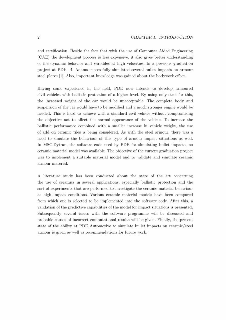
and certification. Beside the fact that with the use of Computer Aided Engineering(CAE) the development process is less expensive, it also gives better understandingof the dynamic behavior and variables at high velocities. In a previous graduationproject at PDE, B. Adams successfully simulated several bullet impacts on armoursteel plates [1]. Also, important knowledge was gained about the bodywork effect.
Having some experience in the field, PDE now intends to develop armouredcivil vehicles with ballistic protection of a higher level. By using only steel for this,the increased weight of the car would be unacceptable. The complete body andsuspension of the car would have to be modified and a much stronger engine would beneeded. This is hard to achieve with a standard civil vehicle without compromisingthe objective not to affect the normal appearance of the vehicle. To increase theballistic performance combined with a smaller increase in vehicle weight, the useof add–on ceramic tiles is being considered. As with the steel armour, there was aneed to simulate the behaviour of this type of armour impact situations as well.In MSC.Dytran, the software code used by PDE for simulating bullet impacts, noceramic material model was available. The objective of the current graduation projectwas to implement a suitable material model and to validate and simulate ceramicarmour material.
A literature study has been conducted about the state of the art concerningthe use of ceramics in several applications, especially ballistic protection and thesort of experiments that are performed to investigate the ceramic material behaviourat high impact conditions. Various ceramic material models have been comparedfrom which one is selected to be implemented into the software code. After this, avalidation of the predictive capabilities of the model for impact situations is presented.Subsequently several issues with the software programme will be discussed andprobable causes of incorrect computational results will be given. Finally, the presentstate of the ability at PDE Automotive to simulate bullet impacts on ceramic/steelarmour is given as well as recommendations for future work.
Chapter 2
State of the art: ceramic
armouring
2.1 Ceramic material
Next to metals and polymers, ceramics constitute one of the three main material classes.They can be defined as compound material between metallic and non-metallic elementshaving interatomic bondings that range from purely ionic to totally covalent having ahard but brittle character. The most ordinary and well-known ceramic materials aretraditional ceramics. They primarily consist of raw materials such as clay, cement orglass. Products that are considered to be made of traditional ceramics are for examplepottery, porcelain, bricks and tiles. Since the 1950s significant progress has been madein the understanding of the fundamental character of ceramic material and the phe-nomena that are responsible for some of their unique properties [2]. Consequently, thevariety of applications has been greatly extended. In table 2.1, an overview is given ofthe most common categories with some examples of applications for each category.
Manufacturing process
Ceramics are formed from a variety of compounds, usually a metallic and nonmetallicelement, such as aluminium and oxide (alumina), calcium and oxygen or silicon andnitrogen. Ceramic products that use naturally occurring minerals first must undergospecial processing in order to control purity, particle size and heterogeneity, beforegoing to production. This is an important part of the manufacturing process, sincethe material structure greatly influences the final properties of the finished material.For chemically prepared powders no such treatment is needed, because they can be
3

4 CHAPTER 2. STATE OF THE ART: CERAMIC ARMOURING
Table 2.1: Industrial use of ceramics [3].
Category ExamplesStructural clay prod-ucts
Brick, sewer pipe, roofing tile, clay floor and walltile
Whitewares Dinnerware, floor and wall tile, sanitaryware ,elec-trical porcelain, decorative ceramics
Refractories Brick and monolithic products are used in iron andsteel, non–ferrous metals, glass, cements, energyconversion, petroleum and chemical industries
Glasses Flat glasses (windows), container glasses (bottles),pressed and blown glasses (dinnerware), glass fibres(home insulation) and advanced/specially glass(optical fibres)
Abrasives Natural (garnet, diamond, etc.) and synthetic (sil-icon carbide, diamond, fused alumina), abrasivesare used for grinding, cutting, polishing
Cements Used to produce concrete roads, bridges, buildings,dams and the like
Advanced Ceramics Structural (bioceramics, armouring, engine compo-nents)Electrical (insulators, integrated circuit packages)Coatings (engine components, cutting tools)Chemical and environmental (membranes, filters,catalysts)
controlled with precise composition and particle size.
As-mined raw material usually has to go through a milling or grinding opera-tion to reduce the particle size and create a powdered product. By the addition ofwater and other ingredients, the minerals become highly plastic and pliable and maytherefore be formed without cracking. Two common shaping techniques are utilised:hydroplastic forming (e.g. extrusion) and slip casting. The liquid which was addedto assist in the forming operation is removed in a drying process. This is manifestedas shrinking. Finally, this so-called green body is baked in an oven between 900 �and 1400 �, called firing or sintering, where diffusion processes cause the body

2.1. CERAMIC MATERIAL 5
Figure 2.1: Overview of production methods for ceramic materials [2].
to shrink further and strength is increased. Another production method is powderpressing. A powdered mass is compacted into a desired shape by pressure. Differentlysized particles are mixed in appropriate proportions to maximise the compaction andminimise the fraction of void space. As the powder particles do not deform plastically,usually a small amount of water or other binder is added to lubricate the particlesas they slide along each other. After the pressing operation, the product needs to befired. The powder particles coalesce into a more dense mass by a sintering process. Acomplete overview of ceramic production methods is shown in figure 2.1.
Ceramic properties
The properties of a material are dictated by the types of atoms present, the typesof bonding between the atoms and the way the atoms are packed together. Ceramicmaterials can be crystalline or amorphous and are usually ionic or covalently bonded.A material held together by either bonding type will tend to fracture before signifi-cant plastic deformation takes place, which results in a poor toughness. Because thesematerials also tend to be porous, the pores and other imperfections lead to stress con-centrations, decreasing the toughness even further. These imperfections combine asthe material is loaded, resulting in brittle failure. The chemical bond for metals on theother hand, called metallic bond, is much weaker than the covalent and ionic bonding,leading in general to a much more ductile failure.
6 CHAPTER 2. STATE OF THE ART: CERAMIC ARMOURING
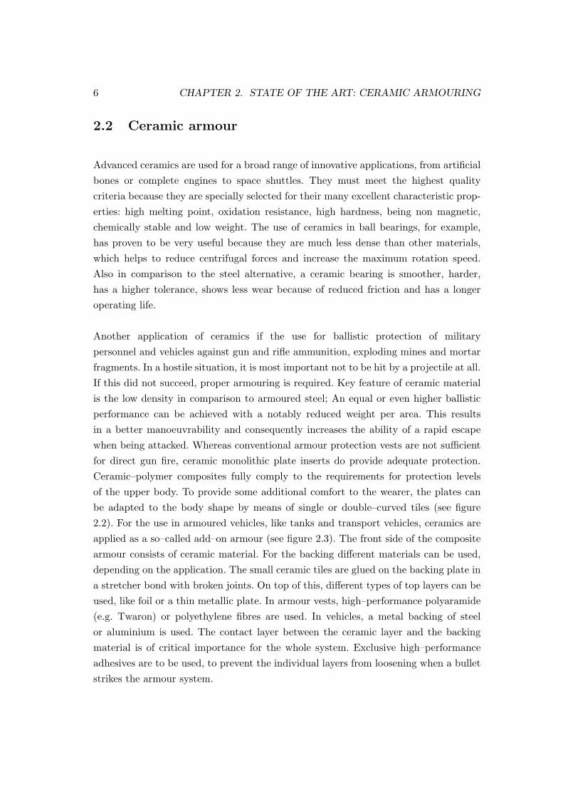
2.2 Ceramic armour
Advanced ceramics are used for a broad range of innovative applications, from artificialbones or complete engines to space shuttles. They must meet the highest qualitycriteria because they are specially selected for their many excellent characteristic prop-erties: high melting point, oxidation resistance, high hardness, being non magnetic,chemically stable and low weight. The use of ceramics in ball bearings, for example,has proven to be very useful because they are much less dense than other materials,which helps to reduce centrifugal forces and increase the maximum rotation speed.Also in comparison to the steel alternative, a ceramic bearing is smoother, harder,has a higher tolerance, shows less wear because of reduced friction and has a longeroperating life.
Another application of ceramics if the use for ballistic protection of militarypersonnel and vehicles against gun and rifle ammunition, exploding mines and mortarfragments. In a hostile situation, it is most important not to be hit by a projectile at all.If this did not succeed, proper armouring is required. Key feature of ceramic materialis the low density in comparison to armoured steel; An equal or even higher ballisticperformance can be achieved with a notably reduced weight per area. This resultsin a better manoeuvrability and consequently increases the ability of a rapid escapewhen being attacked. Whereas conventional armour protection vests are not sufficientfor direct gun fire, ceramic monolithic plate inserts do provide adequate protection.Ceramic–polymer composites fully comply to the requirements for protection levelsof the upper body. To provide some additional comfort to the wearer, the plates canbe adapted to the body shape by means of single or double–curved tiles (see figure2.2). For the use in armoured vehicles, like tanks and transport vehicles, ceramics areapplied as a so–called add–on armour (see figure 2.3). The front side of the compositearmour consists of ceramic material. For the backing different materials can be used,depending on the application. The small ceramic tiles are glued on the backing plate ina stretcher bond with broken joints. On top of this, different types of top layers can beused, like foil or a thin metallic plate. In armour vests, high–performance polyaramide(e.g. Twaron) or polyethylene fibres are used. In vehicles, a metal backing of steelor aluminium is used. The contact layer between the ceramic layer and the backingmaterial is of critical importance for the whole system. Exclusive high–performanceadhesives are to be used, to prevent the individual layers from loosening when a bulletstrikes the armour system.

2.2. CERAMIC ARMOUR 7
Figure 2.2: Armour vest with ceramic insert [4].
Figure 2.3: Add–on armour set–up, consisting of ceramic tiles on top of a layer of glueand a metal backing [4].
To provide maximum protection in the case of multi–hit firing, the ceramic front isbased on 50x50 mm or 100x100 mm tiles. When impacted, only single tiles fracturewhereas a monolithic insert can develop a major crack, which reduces the impactresistance considerably for subsequent shots. The thickness to be chosen depends onthe ballistic performance required and is usually between 5 and 15 mm. Differentshapes, bore holes, or chamfered edges are also available, but need to be customproduced by a diamond cutting machine.

8 CHAPTER 2. STATE OF THE ART: CERAMIC ARMOURING
Ceramic materials used for ballistic protection are required to meet the following prop-erties:
� High hardness
� High fracture resistance
� High E-modulus
� Low weight per area
The requirements for a ceramic material which is to be used for ballistic applicationsare met by several materials. The most important materials which are currently usedare:
� Boron Carbide (B4C)
� Silicon Carbide (SiC)
� Silicon Nitride (SiN)
� Alumina (Al2O3)
� Aluminium nitride (AlN)
From these, Aluminium Oxide, also known as Alumina, is the most important. Thisis due to the fact that its raw material is relatively low cost, that the productiontechnique is well mastered and that the sinter process can be carried out in airatmosphere. The only disadvantage is that the density is higher than for the othermaterials. Aluminium oxide is the main component of bauxite, the principal ore (i.e.raw mining material) of aluminium. It is available in different purities ranging from85% to 99.9%. For ballistic protection, the higher grades (starting from 95%) are morefavourable because of their higher penetration resistance, but are also more expensive.For ballistic protection of objects which need to be extremely light, for examplehelicopters and airplanes, the more expensive but lower density materials as BoronCarbide and Silicon Carbide are used. Two kinds of silicon carbide are available inthe market today; S SiC (sintered silicon carbide) and LPS SiC (liquid phase sinteredsilicon carbide). The difference is that for the LPS process, the sintering temperatureis above the melting point of some of the elements.
The ceramic production technologies should meet high requirements when bal-listic applications are concerned. For all components there should be an absence of

2.3. BULLETS 9
cracks and pores and the finished tiles are only allowed to show very little damageat the edges. Important is also the reproducibility and error–free production ofall individual tiles to ensure that extreme tight tolerances regarding dimension,plane parallelism and evenness are achieved. Only if all these requirements are met,close–jointed packing can be guaranteed. A joint wider than 0.3 mm will already be aweak point which may have a negative influence on the ballistic strength. Beside thegeometrical properties, the physical properties also have little tolerance.
2.3 Bullets
There is a wide variety of bullets, each designed for a specific purpose or target type.In general, two major groups can be distinguished: bullets for wound ballistics andfor armour piercing. Bullets designed to incapacitate personnel or kill animals causean extensive wound by crushing, lacerating or displacing body tissue. When a bulletstrikes into body tissue, a temporary cavity is formed around the crushed tissuewhich results from the acceleration and stretching of soft tissue radial to the woundtrack. This temporary cavity affects solid organs such as the liver and kidneys andthe suction effect draws contaminants such as clothes and bacteria into the woundtrack. Wholly lead bullets deform on impact, resulting in high levels of wounding.The later developed full metal jacketed bullets were more stable and therefore moresuitable for the longer ranges, but had the disadvantage that they did not deform onimpact. Hollow nose semi-jacketed bullets, the so-called Dum–Dum bullets, causedvery extensive wounding and were therefore outlawed by the The Hague Declarationof 1899 [5].
Military bullets are only allowed to have a full metal jacket. To still achieve ahigh wounding potential, the bullets are specially designed to yaw and tumble in thebody after a certain penetration distance. Bullets designed for armour piercing areused to penetrate hardened armour targets such as body armour, vehicle armour,concrete, tanks and other defences. They typically consist of a brass or ordinary steeljacket with a very hard and stiff penetrator like hardened steel, tungsten-carbide ordepleted-uranium. Because of the diversity in bullets, armour materials have to beclassified by their ballistic protection level. Therefore different standards are developedlike EN 1063 (European), NIJ (US), UL (US), DIN or STANAG. In table 2.2 anoverview is given of the European EN 1522 class, which is used within PDE Automotive.
10 CHAPTER 2. STATE OF THE ART: CERAMIC ARMOURING
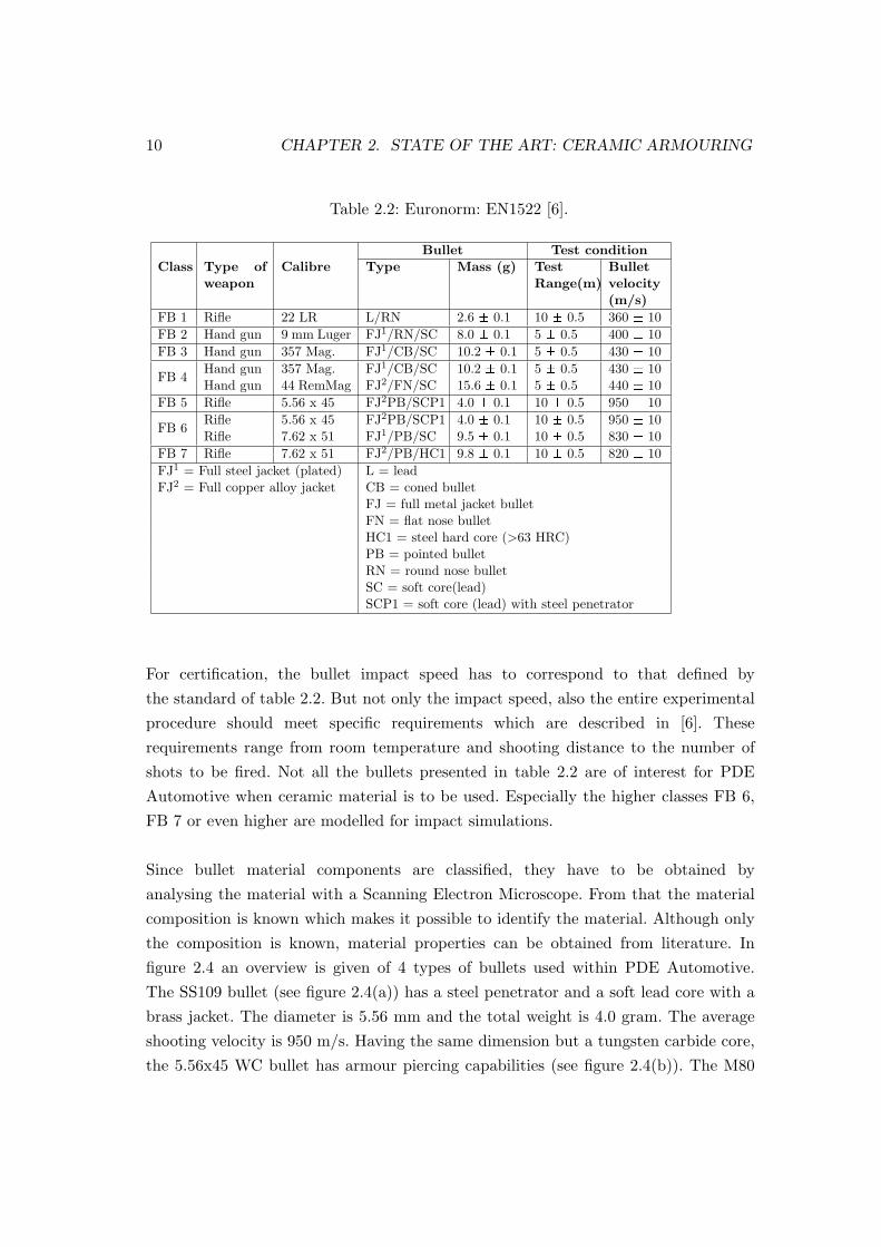
Table 2.2: Euronorm: EN1522 [6].
Bullet Test conditionClass Type of
weaponCalibre Type Mass (g) Test
Range(m)Bulletvelocity(m/s)
FB 1 Rifle 22 LR L/RN 2.6 ± 0.1 10 ± 0.5 360 ± 10FB 2 Hand gun 9 mm Luger FJ1/RN/SC 8.0 ± 0.1 5 ± 0.5 400 ± 10FB 3 Hand gun 357 Mag. FJ1/CB/SC 10.2 ± 0.1 5 ± 0.5 430 ± 10
FB 4Hand gun 357 Mag. FJ1/CB/SC 10.2 ± 0.1 5 ± 0.5 430 ± 10Hand gun 44 RemMag FJ2/FN/SC 15.6 ± 0.1 5 ± 0.5 440 ± 10
FB 5 Rifle 5.56 x 45 FJ2PB/SCP1 4.0 ± 0.1 10 ± 0.5 950 ± 10
FB 6Rifle 5.56 x 45 FJ2PB/SCP1 4.0 ± 0.1 10 ± 0.5 950 ± 10Rifle 7.62 x 51 FJ1/PB/SC 9.5 ± 0.1 10 ± 0.5 830 ± 10
FB 7 Rifle 7.62 x 51 FJ2/PB/HC1 9.8 ± 0.1 10 ± 0.5 820 ± 10FJ1 = Full steel jacket (plated) L = leadFJ2 = Full copper alloy jacket CB = coned bullet
FJ = full metal jacket bulletFN = flat nose bulletHC1 = steel hard core (>63 HRC)PB = pointed bulletRN = round nose bulletSC = soft core(lead)SCP1 = soft core (lead) with steel penetrator
For certification, the bullet impact speed has to correspond to that defined bythe standard of table 2.2. But not only the impact speed, also the entire experimentalprocedure should meet specific requirements which are described in [6]. Theserequirements range from room temperature and shooting distance to the number ofshots to be fired. Not all the bullets presented in table 2.2 are of interest for PDEAutomotive when ceramic material is to be used. Especially the higher classes FB 6,FB 7 or even higher are modelled for impact simulations.
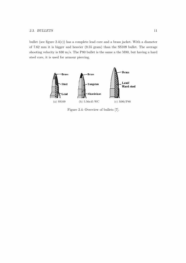
Since bullet material components are classified, they have to be obtained byanalysing the material with a Scanning Electron Microscope. From that the materialcomposition is known which makes it possible to identify the material. Although onlythe composition is known, material properties can be obtained from literature. Infigure 2.4 an overview is given of 4 types of bullets used within PDE Automotive.The SS109 bullet (see figure 2.4(a)) has a steel penetrator and a soft lead core with abrass jacket. The diameter is 5.56 mm and the total weight is 4.0 gram. The averageshooting velocity is 950 m/s. Having the same dimension but a tungsten carbide core,the 5.56x45 WC bullet has armour piercing capabilities (see figure 2.4(b)). The M80
2.3. BULLETS 11
bullet (see figure 2.4(c)) has a complete lead core and a brass jacket. With a diameterof 7.62 mm it is bigger and heavier (9.55 gram) than the SS109 bullet. The averageshooting velocity is 830 m/s. The P80 bullet is the same a the M80, but having a hardsteel core, it is used for armour piercing.
(a) SS109 (b) 5.56x45 WC (c) M80/P80
Figure 2.4: Overview of bullets [7].

12 CHAPTER 2. STATE OF THE ART: CERAMIC ARMOURING

Chapter 3
Material characterisation
The brittle nature of ceramic material and the dynamic nature of the application makesit very difficult to perform traditional material characterisation experiments as used formetals and polymers at low and moderate strain rates, such as a tensile test. Two typesof experiments can be distinguished for obtaining information on ceramics in armourapplications: experiments to evaluate material properties in high strain-rate environ-ments and penetration experiments to evaluate the material behaviour under ballisticimpact conditions. The first type attempts to subject the material to a controlledhigh rate loading with a one or two–dimensional stress-strain state. The penetrationexperiment is a less controlled complex three–dimensional loading condition.
3.1 Plate impact experiments
In plate impact experiments [8] a propellant gas gun accelerates a projectile carrying adisc-shaped sample (i.e. impactor) of the ceramic of interest to velocities up to severalkilometres per second. This impactor undergoes a planar impact with a stationarysample of the same shape and material, generating a shock wave into both disks. Theimpactor and sample dimensions are chosen so that reflected waves from the edges donot reach the centerline in time to interfere with the recording of data. That way auniaxial strain experiment is created. The diameter of the disks thus depends on thespeed of sound of the ceramic used. A thick disk of lithium fluoride is bonded to the backof the stationary disk (see figure 3.1(a)) and performs as a transparent laser interfacewindow for a VISAR (Velocity Interferometer for any Reflecting Surface) system, thatmeasures interface velocity versus time. Some distinct areas can be pointed out. Theinitial part of the wave profile with almost zero rise-time is the elastic wave. It travels
13

14 CHAPTER 3. MATERIAL CHARACTERISATION
(a) Plate impact (b) Wave profile
Figure 3.1: Plate impact experiment [9].
with the longitudinal speed of sound of the ceramic. The break in the curve indicates theHugoniot elastic limit (HEL), which separates the elastic wave from the plastic wave.The HEL is analogous to the yield point in a one–dimensional tensile experiment andthus represents the onset of inelastic behaviour. To calculate the stress at the HEL,the velocity at the HEL in the wave profile is converted with σHEL = ρ0Clv, whereρ0 is the initial density, Cl the material speed of sound and v the material particlespeed. As variation of this experiment, a spall experiment can be conducted, which isused to determine the tensile fracture strength of the ceramic. As the impactor hits thesample disk, a compression waves travels into both disks. In the sample disk, after sometime, the compression wave reaches the lithium fluoride window and, due to the higherimpedance of the ceramic, is reflected as a release wave back to the impact interface(see figure 3.2(a)). In the impactor the compression waves reaches the free surface andis also reflected as a release wave. At some point these two waves interact and cause afracture in the target. In the velocity–time profile this point can be identified by thedip ∆v seen in figure 3.2(b), also called the pull back signal. Because the height of thedip is proportional to the spall strength, it can be related to the tensile fracture stress.
3.2 Bar impact experiments
In this experiment, a long ceramic bar (length/diameter ratio about 4–6) is impacted byeither another bar or a plate. The impacted bar can have two setups; confined and un-confined (see figure 3.3). Just after impact this experiment has much resemblance with

3.3. PENETRATION EXPERIMENTS 15
(a) Wave interaction (b) Pullback signal
Figure 3.2: Tensile fracture strength experiment [9].
the plate impact, but release waves from the edges of the bar cause a two–dimensionalstress and strain loading. Further down the bar, the propagating wave has become aone–dimensional stress wave travelling at the bar wave speed. In figure 3.4 a typicalstress–time profile is shown where the peak stress is a measurement of the maximumstress the rod can support. Results of unconfined and confined experiments are differ-ent because the confinement delays the arrival of unloading waves from the edges ofthe bar and therefore delays failure.
(a) unconfined (b) confined
Figure 3.3: Bar impact experiment [9].
3.3 Penetration experiments
Penetration experiments have such a setup that the investigated ceramic can quali-tatively be tested for real armour applications The goal of penetration experimentsis to analyse the actual ceramic armour application behaviour. A long rod projectile

16 CHAPTER 3. MATERIAL CHARACTERISATION
Figure 3.4: Stress–time profile from bar impact experiment.
penetrates a ceramic body, which can have different dimensions and setups. In a semi–infinite penetration experiment, as shown in figure 3.5(a), the target consists of a thickceramic block covered with a steel or aluminium plate. During testing, the length ofthe penetrator can be measured in time by X–ray. Also the final depth of penetration ismeasured. A different type of penetration experiment is a depth of penetration (DOP)experiment, shown in figure 3.5(b). A ceramic tile is bonded to a thick metal backing ina confined or unconfined configuration. Experimental analysis is done by measuring theballistic performance of the ceramic by the residual penetration depth. This means thefinal penetration into the metal block is compared to the reference penetration depthof the same projectile into the block without the ceramic tile. A special feature is theso–called interface defeat, when the impactor is completely defeated by the ceramictile, resulting in no residual penetration into the steel backing plate.
(a) Semi-infinite (b) DOP
Figure 3.5: Penetration experiments [9].
Chapter 4
Bullet impact experiments
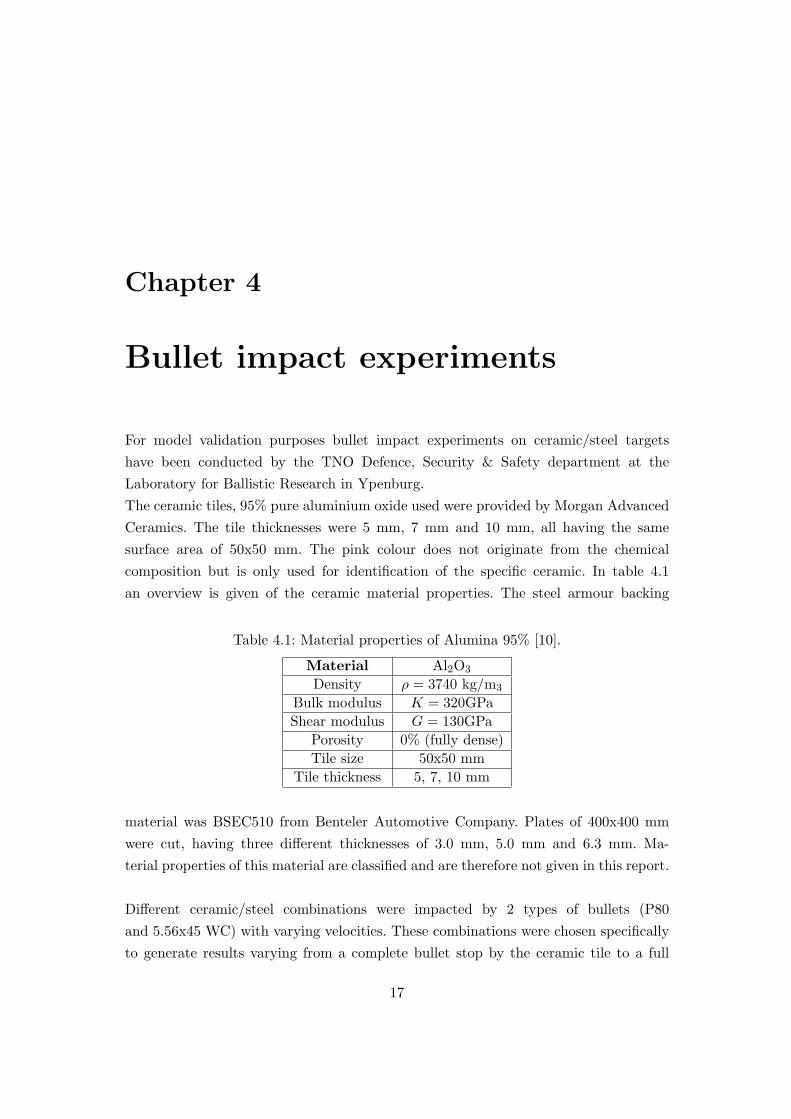
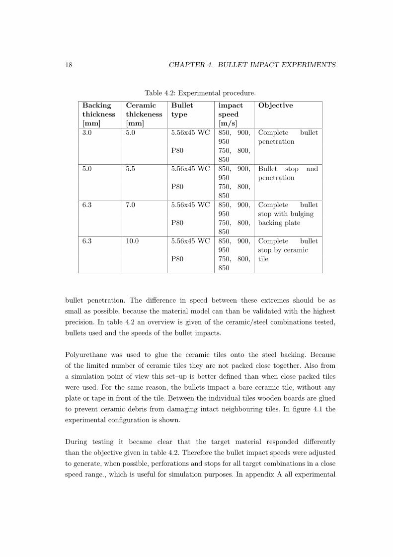
For model validation purposes bullet impact experiments on ceramic/steel targetshave been conducted by the TNO Defence, Security & Safety department at theLaboratory for Ballistic Research in Ypenburg.The ceramic tiles, 95% pure aluminium oxide used were provided by Morgan AdvancedCeramics. The tile thicknesses were 5 mm, 7 mm and 10 mm, all having the samesurface area of 50x50 mm. The pink colour does not originate from the chemicalcomposition but is only used for identification of the specific ceramic. In table 4.1an overview is given of the ceramic material properties. The steel armour backing
Table 4.1: Material properties of Alumina 95% [10].
Material Al2O3
Density ρ = 3740 kg/m3
Bulk modulus K = 320GPaShear modulus G = 130GPa
Porosity 0% (fully dense)Tile size 50x50 mm
Tile thickness 5, 7, 10 mm
material was BSEC510 from Benteler Automotive Company. Plates of 400x400 mmwere cut, having three different thicknesses of 3.0 mm, 5.0 mm and 6.3 mm. Ma-terial properties of this material are classified and are therefore not given in this report.
Different ceramic/steel combinations were impacted by 2 types of bullets (P80and 5.56x45 WC) with varying velocities. These combinations were chosen specificallyto generate results varying from a complete bullet stop by the ceramic tile to a full
17
18 CHAPTER 4. BULLET IMPACT EXPERIMENTS
Table 4.2: Experimental procedure.
Backingthickness[mm]
Ceramicthickeness[mm]
Bullettype
impactspeed[m/s]
Objective
3.0 5.0 5.56x45 WC 850, 900,950
Complete bulletpenetration
P80 750, 800,850
5.0 5.5 5.56x45 WC 850, 900,950
Bullet stop andpenetration
P80 750, 800,850
6.3 7.0 5.56x45 WC 850, 900,950
Complete bulletstop with bulging
P80 750, 800,850
backing plate
6.3 10.0 5.56x45 WC 850, 900,950
Complete bulletstop by ceramic
P80 750, 800,850
tile
bullet penetration. The difference in speed between these extremes should be assmall as possible, because the material model can than be validated with the highestprecision. In table 4.2 an overview is given of the ceramic/steel combinations tested,bullets used and the speeds of the bullet impacts.
Polyurethane was used to glue the ceramic tiles onto the steel backing. Becauseof the limited number of ceramic tiles they are not packed close together. Also froma simulation point of view this set–up is better defined than when close packed tileswere used. For the same reason, the bullets impact a bare ceramic tile, without anyplate or tape in front of the tile. Between the individual tiles wooden boards are gluedto prevent ceramic debris from damaging intact neighbouring tiles. In figure 4.1 theexperimental configuration is shown.
During testing it became clear that the target material responded differentlythan the objective given in table 4.2. Therefore the bullet impact speeds were adjustedto generate, when possible, perforations and stops for all target combinations in a closespeed range., which is useful for simulation purposes. In appendix A all experimental

19
Figure 4.1: Experimental set–up for ceramic/steel target.
results are given as well as a discussion of the results.
Whether the ceramic tile completely stopped the bullet or if penetration oc-curred, the complete tile broke up in pieces and fell off the backing plate. Althoughlarger pieces could be recovered, they could not be used for later analysis, since theydid not originate from the area of interest on the tile, which is located closely aroundthe crack.

20 CHAPTER 4. BULLET IMPACT EXPERIMENTS

Chapter 5
Material modelling
The response of ceramic material to impact loading is of a complex nature. Materialmodels should be able to represent the evolving macro–mechanical material propertieswhich result from the detailed and complex micro–mechanical structure. Damage evo-lution, due to stress concentrations at triple points of grains and in the intergranularglassy phase, should be taken into account. Also the model should have the ability toprovide some compressive strength after the material has failed.First, an overview of existing ceramic materials model is given. Then, the models willbe compared and finally one is selected. This selected model will be discussed in moredetail in section 5.5.
5.1 Simha model
A phenomenological model of the response of a ceramic material under impact loadingconditions is developed by Simha et al. [11] (see figure 5.1) The yield stress, σy, is afunction of the pressure p and the deviatoric strain rate ˙εd. During plastic deformation,damage accumulates until failure (D = 1). The yield stress of the material is a weightedsum of the intact material strength, σintact, and the failed strength, σfailed. Because0 ≤ D ≤ 1 all intermediate states of failure can be described and the material issoftened gradually.
σy = σintact(1−D) + σfailedD +32
˙εd
γ, (5.1)
where
σfailed = min[αp, σmax] γ = γ0 exp[γ1(p− pHEL)],
21

22 CHAPTER 5. MATERIAL MODELLING
Figure 5.1: Simha strength model (without strain rate effect).
with α the slope of the curve shown in figure 5.1, γ0 and γ1 material parameters andpHEL the pressure at the Hugoniot elastic limit, which is the onset of inelastic be-haviour. The term γ controls the contribution of the effective deviatoric strain rate,˙εd to the strength of the material. Taking this rate-dependent term into account isa phenomenological contribution of micro-crack sliding, dislocation activity and grainboundary sliding within the material during deformation. In [11] this model is used forplate impact simulations, depth of penetration simulations and interface defeat com-putations. A very characteristic feature of this model, is the higher material strengthof failed material with respect to intact material.
5.2 Johnson–Holmquist ceramic models
One of the most widely used models for ceramic materials in the ballistic researchfield is the Johnson–Holmquist model. The past several years, these authors developedthree ceramic models [12, 13, 14] (see figure 5.2). All these models (JH–1, JH–2 andJHB) are based on two sets of curves of yield stress vs pressure, i.e. intact and failed.Each curve depends on plastic strain and plastic strain rate. A damage variable, D,defines the level of fracture. For the JH–1 and JHB model, the intact material curveis used prior to fracture (D < 1.0). Once fracture has occurred (D = 1.0) the failedmaterial curve is used. The JH–2 model also has an intact and failed material curve,but the model is gradually softened as damage accumulates.
Most recently Johnson, Holmquist and Beissel developed the so–called JHBmodel [12]. This model is an improved version of the JH–1 model. Material strengthand damage are smooth analytical functions of pressure, whereas JH–1 uses a piecewiseapproximation. In both models the material strength does not decrease until complete

5.3. MICROPHYSICAL MODELS 23
00
Pressure
σ y
P1,σ
1
α
P2,σ
2
−T
Strength ofintact material (D<1)
Strength offailed material (D=1)
(a) JH–1 model (b) JH–2 model
00
Pressure
σ y
Strength ofintact material (D<1)
Strength offailed material (D=1)
Pi,σ
i
−T
Pf,σ
f
(c) JHB model
Figure 5.2: Johnson–Holmquist ceramic models for high pressure, high strain and highstrain rate conditions (at dimensionless strain rate 1.0).
damage (D = 1) has occurred. This in contrast to the JH–2 model which graduallysoftens the material strength (from intact to failed) as damage accumulates.The Johnson–Holmquist models have been used to compute plate impact simulationsand long rod penetrations on silicon carbide and aluminium nitride [15, 16, 17]. Allthese simulations generated acceptable results.
5.3 Microphysical models
The previously mentioned ceramic material models describe the material response froma phenomenological point of view. Intact and failed strength, as well as damage ac-cumulation are functions of pressure. However as damage originates from an existingdistribution of micro-cracks, Rajendran and Groove [18] and Addesio and Johnson [19]developed microphysical models where damage is described by a crack density param-eter. Crack nucleation and growth are based on a generalised Griffith criterion. Due tothis microcracking, a shear modulus and bulk modulus reduction was modelled. These

24 CHAPTER 5. MATERIAL MODELLING
models were used to successfully reproduce velocity histories under one dimensionalstrain conditions. Modelling steel projectile impact on ceramic targets resulted in lessacceptable results, especially for unconfined experiments [18].
5.4 Material model selection
For many ceramic materials, a change in physical (especially mechanical) propertiescan be observed with different physical environments. Compressive strengths andductility may be enhanced under an increased pressure, due to the suppressing orfavouring of certain slip systems [20]. Besides that, strength increases with increasingstrain rate.
Microphysical modelling, which is based on evolving microcracks, is one way ofmodelling ceramic material. But since this theory is only based on a single crackpropagation and no crack interaction is considered, this way of describing the ceramicmaterial response remains to be more phenomenological than properly micromechan-ical based. Therefore, this type of constitutive modelling will not be adopted forcomputations of ceramic impact simulations.
When analysing phenomenological constitutive models, they appear to be inessence a Mohr–Coulomb type of model [11]. This trend is observed by severalauthors. In [21] for example the JH–1 model was simplified and approached by aMohr–Coulomb model. Results of depth of penetration simulations were in reasonableagreement with the experimental data. The ceramic model of Simha [11] appears tobe very appropriate. Computational results are within a few percent of experimentalresults and it also generated the interface defeat feature (i.e. no residual penetrationinto steel backing in a depth of penetration experiment). One part however of themodel is not consistent with any other constitutive model. In the Simha model itis assumed that failed material in compression is stronger than intact material. Thereason given for this is that failed material consists of more (but smaller) particleswith therefore more surface area that interacts during deformation [9]. This increasesthe internal friction, which results is higher strength. This is contradicting with whatis to be expected, because it also can be stated that failed material has almost infiniteslip possibilities, resulting is less strength than intact material, which has a verylimited number of slip systems. Because of this inconsistency, this model will not beselected.
5.5. JOHNSON–HOLMQUIST–BEISSEL MODEL 25
The Johnson–Holmquist models are frequently used in ballistic research of brit-tle materials because of their relatively easy implementation. In Century–DynamicsAUTODYN [22] the first two Johnson–Holmquist models (i.e. JH–1 and JH–2) areimplemented. This software is especially used for simulating impact loading on varioustypes of structures, like spacecrafts, armour material or brick walls. In LS–Dyna[23] these same model are also available to model brittle material behaviour. Inboth program codes the Johnson–Holmquist models generate agreeable results whichtherefore can provide good insight in the ceramic material response. The latest modelhowever, the Johnson–Holmquist–Beissel model (JHB), has not yet been implementedin any of these codes since it is rather new. This model is, as already mentioned, verysimilar to the JH–1 model, both having a discrete damage model. The JH–2 modelis somewhat different since it has a continuous damage model. To model the correctmaterial behaviour, the intact strength of the JH–2 model is always higher than thatof the JH–1 or JHB model, because the damage reduces the strength as plastic strainaccumulates. This eventually results in similar material strengths for all three models.However determination of the JH–2 parameters is more difficult, since the damageevolution has to be taken into account. Therefore the JHB model will be selected to beimplemented into MSC.Dytran to model the ceramic material behaviour. This modelis more favourable than the JH–1 model, since it has smooth analytical functions.
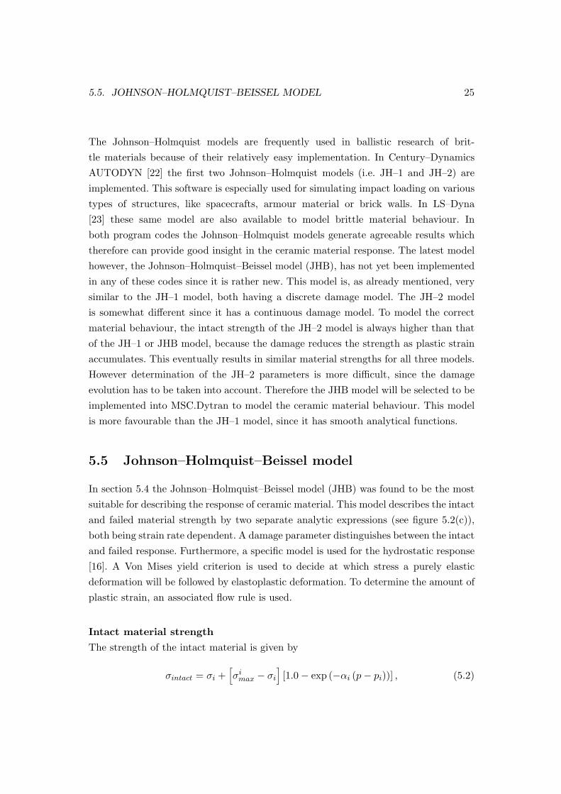
5.5 Johnson–Holmquist–Beissel model
In section 5.4 the Johnson–Holmquist–Beissel model (JHB) was found to be the mostsuitable for describing the response of ceramic material. This model describes the intactand failed material strength by two separate analytic expressions (see figure 5.2(c)),both being strain rate dependent. A damage parameter distinguishes between the intactand failed response. Furthermore, a specific model is used for the hydrostatic response[16]. A Von Mises yield criterion is used to decide at which stress a purely elasticdeformation will be followed by elastoplastic deformation. To determine the amount ofplastic strain, an associated flow rule is used.
Intact material strength
The strength of the intact material is given by
σintact = σi +[σi
max − σi
][1.0− exp (−αi (p− pi))] , (5.2)

26 CHAPTER 5. MATERIAL MODELLING
00
Pressure
σ y
Pi,σ
i
−T
σmaxi
(a) JHB model intact material strength
00
Pressure
σ y
Pf,σ
f σmaxf
(b) JHB model failed material strength
Figure 5.3: Intact and failed material strength for the JHB model
whereαi =
σi
(σimax − σi)(pi + T )
. (5.3)
Here σi, σimax and Pi are material parameters, where the subscript i indicates intact
material. Pressure, p, is defined as p = 13 tr(σ). T is the maximum tensile stress of the
ceramic. Equation (5.2) holds for a pressure greater than pi. For smaller pressures, thestrength is a linear function from σ(p = −T ) = 0 to σ(p = pi) = σi. In figure 5.3(a)the intact material strength is shown with its characteristic points marked.
Failed material strength
The strength of failed material is represented in a similar way as intact material. Forpressures greater than pf , failed material strength is defined by
σfailed = σf +[σf
max − σf
][1.0− exp (−αf (p− pf ))] , (5.4)
withαf =
σf
pf (σfmax − σf )
, (5.5)
where σf , σmax and pf are material parameters and the subscript f denotes the failedmaterial. For pressures smaller than pf the failed strength is a linear function fromσ(p = 0) = 0 to σ(p = pf ) = σf . In figure 5.3(b) the failed material strength is shownwith the characteristic points marked.
Strain rate dependence
Equations (5.2) and (5.4) hold for a dimensionless strain rate of ε∗ = 1.0, whereε∗ = ˙ε/ε0, with ε0 the reference strain rate and ˙ε the effective strain rate. To include

5.5. JOHNSON–HOLMQUIST–BEISSEL MODEL 27
00
Pressure
Fai
lure
str
ain
−T
εpf =D
1(P*+T*)n
Figure 5.4: Plastic strain to failure in JHB model.
strain rate dependence, the strength at other effective strain rates is defined as
σy = σξ(1.0 + C ln ε∗), (5.6)
where C is the dimensionless strain rate constant and σξ is the material strength withξ = intact, failed, denoting intact (eq. 5.2) and failed (eq. 5.4) material, respectively.
Damage
The JHB model has a pressure dependent damage model included. Damage is accu-mulated in a similar manner as in the Johnson–Cook failure model (which will bediscussed in section 5.6) and is defined as:
D =∑ ∆εp
εfp
, (5.7)
where ∆εp is the current increment in equivalent plastic strain. The plastic strain tofailure, εf
p , is defined asεfp = D1(P ∗ + T ∗)n, (5.8)
where D1 and n are dimensionless constants. T ∗ = T/σimax and P ∗ = P/σi
max aredimensionless pressures. The material fails if damage, D, equals unity or if the tensilehydrostatic pressure is greater than the maximum tensile pressure, T . Once the materialhas failed, no damage will be accumulated anymore and damage is set to D = 1. Infigure 5.4 the plastic strain to failure is shown.

28 CHAPTER 5. MATERIAL MODELLING
Pressure
In compression the hydrostatic pressure-volume response before failure is a polynomialfunction of the volumetric compression, µ:
P = K1µ + K2µ2 + K3µ
3, (5.9)
where K1 is the bulk modulus, K2 and K3 are material fitting parameters. The volu-metric compression, µ, is defined as
µ =V0
V− 1 =
ρ
ρ0− 1, (5.10)
with V0 and V the initial and current volume respectively and ρ0 and ρ the initial andcurrent density. After complete failure has occurred the dilatancy occurs because of apressure and/or volume increase [24]. Therefore an additional pressure, ∆P , is addedto equation (5.9). This pressure increase is determined by energy considerations. Theloss of internal elastic energy, ∆U , is converted into potential hydrostatic energy. Thederivation of this is given in Appendix B.The pressure increase is defined as
∆P = −K1µf +√
(K1µf )2 + 2βK1∆U, (5.11)
with β the fraction of converted internal energy loss (0 ≤ β ≤ 1) and µf the volumetriccompression at failure.
In tension, the pressure is represented by a linear dependence on the volumetricstrain:
P = K1µ. (5.12)
If the material fails under tension no bulking pressure is computed.
5.6 Material models for metals
Steinberg–Guinan
The Steinberg–Guinan model [25] is applicable for metals subjected to high strainrates. In the work of B. Adams [1] this model was used for copper in bullet impactsimulations. The material strength, σy, increases with increasing pressure and decrease
5.6. MATERIAL MODELS FOR METALS 29
with increasing temperature. The flow stress is written as:
σy = [A + B (εp + ε0)n]
[1 + H1
P
J13
−H2 (T − Tr)],
where A is the initial yield stress, B and n work–hardening parameters, εp the equiv-alent plastic strain, ε0 the initial equivalent plastic strain, T the temperature and Tr
the room temperature. H1 and H2 are material parameters.
Johnson–Cook model
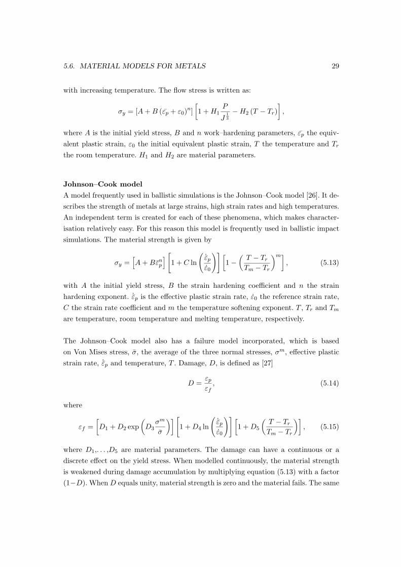
A model frequently used in ballistic simulations is the Johnson–Cook model [26]. It de-scribes the strength of metals at large strains, high strain rates and high temperatures.An independent term is created for each of these phenomena, which makes character-isation relatively easy. For this reason this model is frequently used in ballistic impactsimulations. The material strength is given by
σy =[A + Bεn
p
] [1 + C ln
(˙εp
ε0
)] [1−
(T − Tr
Tm − Tr
)m], (5.13)
with A the initial yield stress, B the strain hardening coefficient and n the strainhardening exponent. ˙εp is the effective plastic strain rate, ε0 the reference strain rate,C the strain rate coefficient and m the temperature softening exponent. T , Tr and Tm
are temperature, room temperature and melting temperature, respectively.
The Johnson–Cook model also has a failure model incorporated, which is basedon Von Mises stress, σ, the average of the three normal stresses, σm, effective plasticstrain rate, ˙εp and temperature, T . Damage, D, is defined as [27]
D =εp
εf, (5.14)
where
εf =[D1 + D2 exp
(D3
σm
σ
)] [1 + D4 ln
(˙εp
ε0
)] [1 + D5
(T − Tr
Tm − Tr
)], (5.15)
where D1,. . . ,D5 are material parameters. The damage can have a continuous or adiscrete effect on the yield stress. When modelled continuously, the material strengthis weakened during damage accumulation by multiplying equation (5.13) with a factor(1−D). When D equals unity, material strength is zero and the material fails. The same

30 CHAPTER 5. MATERIAL MODELLING
holds for a discrete damage effect, but than material fails instantly when D reachesunity.

Chapter 6
MSC.Dytran code
For calculating the mechanical response of material during impact simulations, withinPDE Automotive the finite element code MSC.Dytran is used. This program uses anexplicit method to solve the equation of motion, given in equation 6.1 [28]
Mu˜t + Cu˜t + Ku˜t = F˜ t, (6.1)
where M is the mass matrix, C the damping matrix and K the stiffness matrix. Thecolumns u˜t, u˜t, u˜t and F˜ t are the nodal accelerations, velocities, displacements andforces, respectively. The equation of motion at the current time t is used to predict asolution of the acceleration at time t+∆t. The equilibrium determines the accelerationat the beginning of the increment and it is assumed to be constant over the time step,∆t. Therefore equation 6.1 can be rewritten as [1]:
u˜t+∆t = M−1F˜rest . (6.2)
To advance in time, nodal velocities and displacements are calculated by [1]:
u˜t+∆t = u˜t + ∆tu˜t+∆t (6.3)
andu˜t+∆t = u˜t + ∆tu˜t+∆t. (6.4)
In figure 6.1 the calculation loop is shown, carried out by MSC.Dytran each timestep, to calculate the material response. Because the accelerations are assumed to beconstant over the time step, the time step has to be chosen small. For stability reasonsit must be chosen smaller than the smallest natural period in the mesh. This means,
31

32 CHAPTER 6. MSC.DYTRAN CODE
Figure 6.1: Diagram of loop carried out by MSC.Dytran each time step [28]
the time step has to be smaller than the time for a stress wave to travel through thesmallest element.
Within the MSC.Dytran code, two solving techniques are available, Langrianand Eulerian (see figure 6.2). The code can use either one, or both, and can couplethe two types to define an interaction. In the Lagrangian approach, nodes correspondto material points. During deformation, the grid points move, distorting the element.In the Eulerian approach, the mesh has a fix reference frame, which means that gridpoint are fixed in space and material flows through the elements. The mesh itself isdefined the same as for the Lagrangian approach, only the use is different because themesh for the Eulerian approach should be large enough to contain the material afterdeformation. Unless specified, the material is not allowed to cross the boundary of themesh, which therefore act as a boundary condition. In general, a Lagrangian approachis used for engineering applications. The Eulerian solver is used for fluids or materialsthat undergo very large deformations [28]. Because bullet impact experiments shownvery large deformations, an Eulerian approach will be used to simulate these kindof experiments. Therefore an explanation will be given of some important numericalaspects when working within an Eulerian domain.
Following the scheme presented in figure 6.1, at the beginning of an increment

33
(a) Lagrange
(b) Euler
Figure 6.2: Lagrange and Euler approach [28].
the grid point velocities are known. From this, the transported volume V can bedetermined by
V = v·A·∆t, (6.5)
where v is the speed of the moving material in normal direction of the boundarysurface,A, the material passes and ∆t is the time step. Now the transported volumefrom donor to acceptor element is known, it can be filled up with mass of the donorelement by using the donor material density. When more than one material is presentin an element, the transported volume can be filled up with more than one material.In order to maintain an interface between different materials, this is done in aspecific order. If the donor and acceptor element have common material, this will betransported first. If there still remains volume to be filled up, the remaining materialin the donor element will be transported according to the largest material fraction inthis element.
To calculate elemental stresses and strains, different subroutines are used. Thepressure (or hydrostatic stress), is determined by an equation of state subroutine. Inthe yield stress subroutine, the yield stress is calculated by selecting one the availableyield models. To initiate damage and/or finally failure, a failure routine has to be used.When a specific pressure, yield and/or failure model is not present in the MSC.Dytranlibrary, users can program their own subroutine by so–called user subroutines.Since the Johnson–Holmquist–Beissel model was not included in the MSC.Dytranmaterial models library, it therefore had to be programmed. Although the user isfree of programming within the user subroutine, some special features, needed for

34 CHAPTER 6. MSC.DYTRAN CODE
incorporating the JHB model, were not available. In cooperation with MSC.Softwarethe user subroutine for damage was adjusted so that a material failure would not leadto zero strength, as would happen in the standard code. Also the user subroutinefor the equation of state was modified to be able to account for the additional pressure.
In MSC.Dytran, no conventional axisymmetric elements are available. Althoughthis shortcoming, axisymmetric can be performed by using a 5°wedge. On thecenterline, 6–node pentahedral elements are used. For the remaining part of the mesh,8–node hexahedral elements are used. In tangential direction there is only 1 element.Since the edge length in tangential direction of the pentahedral elements is small, thetime step also becomes very small. Because there is no material flow in this direction,the time step is much smaller than needed for still being able of generating stableresults. To increase the time step and reduce calculation time, an axial symmetryoption is used. The time step is then determined only by element sizes in radial andaxial direction. Also, this option aligns all the element face normals in tangentialdirection, so that all element faces are in one plane. Without the axial symmetryoption, this may not be the case because of round–off differences.

Chapter 7
Model validation
To validate the implementation of the Johnson–Holmquist–Beissel model (JHB), inMSC.Dytran various simulations have been conducted. These applications differ fromthe one–dimensional strain response to complex three–dimensional behaviour. The sim-ulations are compared to experimental results and to computations performed by otherauthors as well. In all examples, silicon carbide (SiC) is considered, for which the con-stants for the JHB model are shown in table 7.1
Table 7.1: Constants for the JHB model for Silicon Carbide [16].
parameter ValueDensity ρ0 = 3215 kg/m3
Shear modulus G = 193 GPaHydrostatic tensile strength T = 0.75 GPaIntact strength constant σi = 4.92 GPaIntact strength constant Pi = 1.5 GPaMaximum intact strength σmax = 12.2 GPaStrain rate constant C = 0.009Failure strength constant σf = 0.10 GPaFailure strength constant Pf = 0.25 GPaMaximum failure strength σf
max = 0.20 GPaBulk modulus K1 = 220 GPaPressure coefficient K2 = 361 GPaPressure coefficient K3 = 0 GPaDamage coefficient D1 = 0.16Damage exponent n = 1.0Energy conversion factor β = 1.0
35

36 CHAPTER 7. MODEL VALIDATION
7.1 Plate impact
Plate impact experiments, as mentioned in chapter 3, are frequently used for modelvalidation purposes. Grady and Moody performed extensive research on the impactresponse of several ceramic materials [29]. Johnson and Holmquist [16] simulated twosilicon carbide plate impact experiments from Grady and Moody [29],using the JHBmodel within a Lagrangian finite element approach. The same simulations have beenperformed using MSC.Dytran with the implemented JHB model. The thickness of thesilicon carbide target is 9 mm and is backed by a lithium fluoride (LiF) window with athickness of 25.4 mm. The silicon carbide projectile with a thickness of 4.5 mm has apolymethyl methacrylate (PMMA) backing with a thickness of 8.0 mm. Both simula-tion have the same configurations but differ in speed. One impact is at 2259 m/s, theother at 1566 m/s.
Table 7.2: Material constants for LiF [30] and PMMA [9].
Material ρ0 G K A B
LiF 2638 kg/m3 49 GPa 63 GPa 360 MPa 0n H1 cp Tm
0 -3.028 MPa 129 J/kg� 1207 �
Material ρ0 G σy
PMMA 1180 kg/m3 2.3 GPa 190 MPaK1 K2 K3
6 GPa 29 GPa 13 GPa
During the experiments Grady and Moody measured the particle velocity of thesample–window interface and plotted this against time. In order to compare the com-puted results with experimental data, the same information needed to be obtained fromthe simulation in MSC.Dytran. Since the JHB model is only available in an Eulerianapproach, tracking a single material point is not possible (i.e. material travels fromelement to element). Therefore a Lagrange–Euler interface has been modelled, withthe window material defined in a Lagrangian mesh. In figure 7.1, the simulation setupused in MSC.Dytran is shown. To assure axial symmetry, the bottom notes of the La-grangian mesh are constrained in radial direction. The right bottom node is constrainedin all directions. The free surface at the back of the Lagrange mesh is constrained notto move in axial direction. The remaining nodes are not allowed to move in tangentialdirection. Although this is a simplification of the actual experimental set–up, it is how-ever permitted since the recording time is of such short period that this constraining

7.1. PLATE IMPACT 37
Figure 7.1: Plate impact setup with Eulerian and Lagrangian elements
0 0.5 1 1.5 2 2.5
x 10−6
0
200
400
600
800
1000
1200
time [s]
Par
ticl
e sp
eed
[m
/s]
ExperimentsJohnson−HolmquistMSC.Dytran
(a) 1566 m/s
0 0.5 1 1.5 2 2.5
x 10−6
0
500
1000
1500
time [s]
Par
ticl
e sp
eed
[m
/s]
ExperimentsJohnson−HolmquistMSC.Dytran
(b) 2259 m/s
Figure 7.2: Silicon carbide plate impact data at two different impact speeds.
does not influence the results. The Eulerian mesh consisted of 22500 elements with anelement size of 0.1x0.2 mm. The Langragian mesh consisted of 29680 elements withan element size of 0.1x0.25 mm. A Steinberg–Guinan model is used to model the LiFwindow. To model the PMMA backing an elastic perfectly plastic model is used. Intable 7.2 the material parameters for LiF and PPMA are shown. In figure 7.2, data isplotted of results obtained from MSC.Dytran using the implemented JHB model, theexperimental data of Grady and Moody and results of Johnson and Holmquist alsousing the JHB model. It can be seen that there is good agreement between the individ-ual results. Although the release waves of both simulated results show some differenceswith the experimental results, they show very similar behaviour.

38 CHAPTER 7. MODEL VALIDATION
(a) Target configuration repro-duced from [32]
(b) Wedge shape simulationconfiguration
Figure 7.3: Thick target geometry.
7.2 Thick target impact
Lundberg et al [31] performed experiments on thick confined silicon carbide targetsimpacted by long rods. In figure 7.3, the target geometry is presented. The Eulerianmesh contains 69080 elements with an element size of 0.1 mm. The projectile is atungsten rod of 80 mm in length and 2 mm in diameter. The silicon carbide target isconfined by a high strength steel tube (S–7 steel) with a steel top and bottom plug(4340 steel). The target dimensions are 20 mm in diameter and 20 mm in height.The steel tube is 28 mm in diameter with a height of 36 mm. The plugs are both20 mm in diameter and 8 mm in height. The Johnson–Cook strength and fracturemodel constants to model the materials of the confinement are given in table 7.3. Infigure 7.4 computed results are presented together the experimental data. The threeimpact velocities are 1410, 1645 and 2175 m/s and are identical to the velocities usedin the experiments. Also plotted in this figure are results from [32] where the sameexperiments were simulated using the JH–1 model in a Lagrangian mesh and meshlessparticles. The mesh initial only held Lagrangian elements, which were automaticallyconverted into meshless particles during the course of computations. The simulationsperformed with MSC.Dytran and from [32] show similar behaviour. Both generate a

7.2. THICK TARGET IMPACT 39
Table 7.3: JC material constants for 4340 steel, S–7 steel and tungsten [26, 27, 17, 32].
Material 4340 steel S–7 steel Tungstenρo (kg/m3) 7850 7750 17600G (GPa) 78 78 124K1 (GPa) 164 164 285K2 (GPa) 294 0 470K3 (GPa) 500 0 335Tm (�) 1520 1490 1768
cp (J/kg�) 477 475 250A (MPa) 600 2000 1300B (MPa) 510 477 141
n 0.26 0.18 0.18C 0.014 0.012 0.016m 1.03 1.0 1.0D1 0.05 -0.80 0D2 3.44 2.10 0.33D3 -2.12 -0.50 -1.50D4 0.0020 0.0020 0D5 0.61 0.61 0
slightly to high penetration depth for 1410 m/s and 2175 m/s with respect to the ex-perimental results. The evolution of penetration in MSC.Dytran at 1645 m/s howeverdiffers from the experimental results as well as from the computational results from [32].
Materials defined in an Eulerian based approach that have coinciding surfacesare considered to be bonded together. At the contact surface there is no frictiondefined, only the shear modulus of both materials has influence on the resistanceagainst movement. Separating the materials is only possible when internal forces arein opposite direction. This is also the case when a real interface (without any bonding)is present, but the force needed in simulations is higher, because the material areconsidered to be bonded together. When the tungsten cylinder arrives at the interfaceof the steel plug and the ceramic block, dwelling occurs (i.e. during a short periodof time the impactor continuous to deform without any penetration into the ceramicmaterial). During the dwelling, the tungsten therefore has to flow radially betweenthe contacting surfaces of the ceramic block and the steel plug by separating thesematerials from another. In the experimental configuration, the plug and the ceramicblock are placed against each other without any bonding forces. In the Euleriansimulations there is a bonding though, thereby restricting the radial movement of the

40 CHAPTER 7. MODEL VALIDATION
0 1 2 3 4
x 10−5
0
5
10
15
20
25
time [s]
Cer
amic
pen
etra
tio
n [
mm
]
MSC.Dytran
Johnson−HolmquistV = 2175 m/s
V = 1645 m/s
V = 1410 m/s
Experiment
Figure 7.4: Thick Target impact results at various speeds.
tungsten at the steel plug/ceramic interface. In figure 7.5 is shown what takes placeduring the simulation at the interface. Instead of flowing radially the tungsten materialstarts to swirl. This has an effect on the penetration progress. During the 1645 m/simpact simulation the swirling of the tungsten at first delays the penetration into theceramic. Once less projectile material flows into the swirl during the movement of theprojectile, the penetration is increased because more projectile material is now usedto penetrate the target material. The swirl creates an open space and therefore morematerial is flowing into this area resulting in less material penetrating the ceramicblock. This space would not be present in this amount when the tungsten material flowwas more radial. The open area created would be filled sooner, forcing the projectileto penetrate into the ceramic, leading to a more continuous penetration.For the tungsten not being able to have enough radial flow at the steel plug/ceramicinterface also results in the larger penetration results of the 1410 m/s impact simula-tion. Since the material cannot move enough in radial direction, it will flow into theceramic block, resulting in some penetration.
Figure 7.6 shows the damage contour at several simulation times. Very clearlycan be observed the forming of radial cracks as well as the typical creation of thedamage conoid in front of the projectile. Because of wave reflection at the ceramic/steel

7.2. THICK TARGET IMPACT 41
plug interface at the bottom, a fracture conoid is also formed from this surface upwardsto the projectile. This type of behaviour is typically what is to be expected as ceramicmaterial response to impact loading conditions [16].
(a) 12 µs (b) 18 µs (c) 24 µs (d) 30 µs
Figure 7.5: Material movement during a thick target impact simulation at v=1645 m/s.
(a) 8 µs (b) 12 µs (c) 14 µs (d) 16 µs
Figure 7.6: Damage contour of thick target impact simulation at v=2175 m/s.

42 CHAPTER 7. MODEL VALIDATION

Chapter 8
Numerical issues in MSC.Dytran
The validity of some of the results generated during the performed simulations werequestioned because of unexpected material responses. Before performing actual impactsimulations which are to be used as a replacement for experiments, it is necessaryto find the origin of these inconsistencies and, if possible, solve the problems. In thework of B. Adams [1], the steel parameters used were obtained by fitting numericalsimulations to bullet impact experiments. The steel used there was designated asBSEC180. The steel used in the experiments of chapter 4, designated as BSEC510,differed from the BSEC180 steel (i.e. the BSEC510 material had less ballistic protec-tion capabilities). For this reason, an adjustment of the material parameters obtainedby B. Adams was required.
Various bullet impact experiments on BSEC510 plates were conducted by BentelerAutomotive. The results from these experiments were used to determine the BSEC510material parameters. From the experimental data, two sets of bullet impacts wereused which are given in table 8.1. All bullets were launched at the same steel plate,
Table 8.1: Bullet impact data used for BSEC510 material fitting.
Bullet type Impact velocity(m/s)
Result
SS109 550 Stop, small bulge560 Full penetration (bullet
diameter size hole)M80 870 Stop, heavy bulge
880 Full penetration (bulletdiameter size hole)
43

44 CHAPTER 8. NUMERICAL ISSUES IN MSC.DYTRAN
(a) SS109 (b) M80
Figure 8.1: Initial configuration for simulations of bullet impacts on a 6.3 mm steelplate.
which had a thickness of 6.3 mm. A numerical simulation of these experiments wasused to obtain the constitutive parameters of the target material. In figure 8.1 thesimulation configuration is shown.
8.1 Voids
The axial symmetry option, mentioned in chapter 6, reduces calculation time signifi-cantly by increasing the time step of the simulation. However when using this option,computed results differ from those obtained with a simulation performed without thisoption set. In figure 8.2 two M80 bullet impacts at 870 m/s on a 6.3 mm steel plateare shown with and without the axial symmetry option being activated. Without theaxial symmetry option, the bullet is completely stopped by the steel plate, whereasin case the axial symmetry option is used, the bullet penetrates the plate. When theaxial symmetry option is activated, in every simulation, regardless of the materialparameters, a cracks develops at the back of the steel plate (see figure 8.3). In order tobe able to stop the bullet at this speed, the material should bulge significantly. Thishowever is not possible since the material cracks when the material starts to bulge.This cracking is caused by the development of voids at the back of the plate.
A void is an element where the stress and the pressure are set to zero. It con-tains a certain amount of material mass (or no mass at all) that causes the pressureto be less than the limited minimum pressure (pmin). When there is a very small

8.1. VOIDS 45
(a) Without option activated (b) With option activated
Figure 8.2: Significant difference in results when using the axial symmetry option.
Figure 8.3: Loss in material when using the axial symmetry option.
amount of mass present in an element, the density (which is defined by the mass insidethe element and the element volume) becomes very small with respect to the initialmaterial density. This causes the volumetric strain, defined in equation (5.10), toapproximately equal −1. Calculating in that case the pressure would give a value closeto −K, with K the bulk modulus (assuming a linear pressure model). To avoid anelement to have a pressure of the physical impossible value of −K, the limit pressureis set slightly above −K.
To calculate the void fraction in an element the following equation is used
FV =Vm −
(mρ0
)
Vm, (8.1)

46 CHAPTER 8. NUMERICAL ISSUES IN MSC.DYTRAN
where FV is the void fraction, Vm, the current volume occupied by the mass presentin the element, m, the mass in the element and ρ0 the reference density. The term(
mρ0
)represents the volume that the mass would occupy if it had the reference density.
An element is considered to be void if the void fraction is greater than a definedtolerance fraction, FVtol. Note that equation 8.1 is only used in case the pressure isless the pmin. This means that only if the calculated element pressure is less than pmin
a void fraction, calculated by equation 8.1), that is larger than FVtol leads to a voidelement. If an element already had a void fraction the previous increment, negativepressures are not allowed. Therefore a void can only generate stress and pressureagain, if enough mass has entered the element to generate a positive pressure. In thatcase the void fraction will be less than FVtol. In that case the void fraction of theelement will be set to zero.
Figure 8.4: Computed and manually calculated values of 4 elements near and at thevicinity of the crack initiation.
Looking closely at what happens at the position where the crack starts to grow it be-comes clear that the void fraction is not calculated correctly. In figure 8.4 the elementoutput of 4 elements near and at the vicinity of the crack initiation is given togetherwith manually calculated values, calculated from the current element data. Element1, 2 and 4 are correctly calculated by MSC.Dytran. Note that manually calculatedvalues can show a small difference from computed values, because MSC.Dytranperforms calculations with double precision. The manually calculated values arecalculated with single precision. The void fractions of elements 2 and 4 are greater

8.2. BULLET IMPACT FITTING 47
than the tolerance void fraction, which is set to be 6.10−4. This however, does not leadto a void fraction, because the element pressure is greater than the limit pressure, pmin.
Element 3 however, had a void fraction after the previous increment. To beable to contain non–zero pressures, the element first should have enough mass togenerate a positive pressure (which is not the case). Although a negative pressureis being generated during the increment, a void fraction of FV = 0 is computed byMSC.Dytran. The manually calculated value however indicates a void fraction largerthan the tolerance value of FVtol = 6.10−4, which should lead to a void element.As a consequence, element 3 is capable of having tensile stresses, while element 1 isnot. This leads to material separation at this point which is manifested by a crackinitiation. The steel plate therefore is not able of bulging anymore but starts tofracture and hence the bullet is not stopped. Performing calculations with the axialsymmetry option activated with a time step close to the time step used by the codewhen axial symmetry is not active, leads to results similar to those computed whenthe axial symmetry options is not activated. Therefore the larger time step source ofthe inaccurate void fraction calculations.
8.2 Bullet impact fitting
Because of the inconsistencies discussed in the previous section the axial symmetryoption will not be used for bullet impact simulations. In table 8.1, an overview isgiven of the data which will be used for determining the values of the BSEC510 steelparameters values for the Johnson–Cook model. For each bullet type the ballisticlimit velocity, the velocity at which 50% of the bullets fired will be stopped, wastaken within 10 m/s to guarantee an accurate material fitting. Using the materialparameters obtained by Adams [1] as a first approximation, it was expected thatthe parameters should not be altered extensively. During the simulations, however, adiscrepancy occurred (see figure 8.5).
Parameter set 1 represents a material with a higher strength than parameterset 2. Using the first set an M80 bullet impacting at 870 m/s is stopped as wellas an SS109 bullet impacting at 960 m/s. According to table 8.1, the M80 bulletshould indeed be stopped but the SS109 bullet should penetrate the steel plate. Togenerate this result, the material parameters should be changed such that bulletpenetration and bullet stops would occur at the proper velocities, described in 8.1.

48 CHAPTER 8. NUMERICAL ISSUES IN MSC.DYTRAN
(a) SS109 bullet at 960 m/s against a6.3 mm BSEC510 steel plate withparameter set 1
(b) M80 bullet at 870 m/s against a6.3 mm BSEC510 steel platewithparameter set 1
(c) SS109 bullet at 960 m/s againsta 6.3 mm BSEC510 steel platewithparameter set 2
(d) M80 bullet at 870 m/s against a6.3 mm BSEC510 steel platewithparameter set 2
Figure 8.5: Discrepancy in BSEC510 material fitting.
The second set has a reduced strength but looking at figure 8.5(c) and 8.5(d) the steelplate still stops the SS109 bullet but is penetrated by the M80 bullet. This resultsin an impossible situation because the material should have a higher strength whenimpacted by a M80 bullet and a reduced strength when impacted by a SS109. Afterperforming calculations with a large number of other parameter sets, the discrepancystill occurred. Therefore it must be concluded that the material parameters for theBSEC510 steel can not be uniquely determined.
8.3 Depth of penetration
Depth of penetration tests (DOP), mentioned in section 3.3, are frequently used toinvestigate the ballistic performance of ceramic material. The depth of penetration into

8.3. DEPTH OF PENETRATION 49
(a) Simulation configuration (b) Computational result at v=1770 m/s
Figure 8.6: Depth of penetration experiment setup and computational result.
a steel block with a ceramic tile in front of it, is compared to the depth of penetrationthe same projectile has into the bare steel, impacted with the same velocity (seefigure 8.6(a)). In [33], five ceramics were impacted by a tungsten projectile and backedby a thick steel block. This data could be used to further validate the JHB modelimplementation and to determine JHB material parameters of other types of ceramics,like aluminium oxide.
Before fitting the ceramic material parameters, the impact into the bare steel blockis modelled to determine the accuracy of the Johnson–Cook model in MSC.Dytran.In [17], the experiments have also been simulated. The material parameters usedin these simulations are given in table 8.2. Using the these parameters, the samesimulations were performed in MSC.Dytran. In figure 8.6(b), the computed result isgiven of a tungsten projectile with an impact velocity of 1770 m/s into the bare steelblock. The final depth of penetration is 30 mm, but according to the experimentaldata, this should be 36 mm [33]. When comparing the results from MSC.Dytranwith results from [17], which are very close to the experimental data, there is asignificant difference. However, the only difference between both simulations is thatthe simulations in [17] are performed with a Lagrangian approach. When lookingin detail at how the Johnson–Cook model is programmed in MSC.Dytran, a fewinconsistencies can be observed:
� The material parameter D3 in the Johnson–Cook damage model (see equation(5.15)) determines the influence of the mean stress to equivalent stress ratio,
(σmσ
)
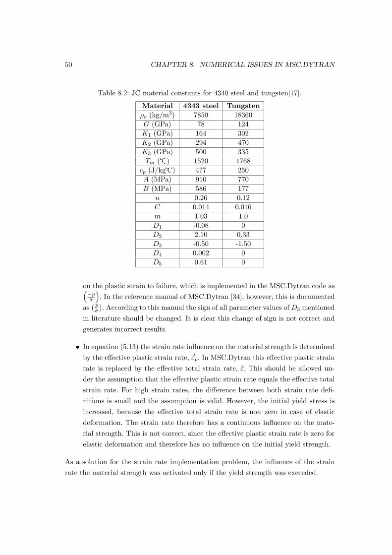
50 CHAPTER 8. NUMERICAL ISSUES IN MSC.DYTRAN
Table 8.2: JC material constants for 4340 steel and tungsten[17].
Material 4343 steel Tungstenρo (kg/m3) 7850 18360G (GPa) 78 124K1 (GPa) 164 302K2 (GPa) 294 470K3 (GPa) 500 335Tm (�) 1520 1768
cp (J/kg�) 477 250A (MPa) 910 770B (MPa) 586 177
n 0.26 0.12C 0.014 0.016m 1.03 1.0D1 -0.08 0D2 2.10 0.33D3 -0.50 -1.50D4 0.002 0D5 0.61 0
on the plastic strain to failure, which is implemented in the MSC.Dytran code as(−pσ
). In the reference manual of MSC.Dytran [34], however, this is documented
as( p
σ
). According to this manual the sign of all parameter values of D3 mentioned
in literature should be changed. It is clear this change of sign is not correct andgenerates incorrect results.
� In equation (5.13) the strain rate influence on the material strength is determinedby the effective plastic strain rate, ˙εp. In MSC.Dytran this effective plastic strainrate is replaced by the effective total strain rate, ˙ε. This should be allowed un-der the assumption that the effective plastic strain rate equals the effective totalstrain rate. For high strain rates, the difference between both strain rate defi-nitions is small and the assumption is valid. However, the initial yield stress isincreased, because the effective total strain rate is non–zero in case of elasticdeformation. The strain rate therefore has a continuous influence on the mate-rial strength. This is not correct, since the effective plastic strain rate is zero forelastic deformation and therefore has no influence on the initial yield strength.
As a solution for the strain rate implementation problem, the influence of the strainrate the material strength was activated only if the yield strength was exceeded.

8.3. DEPTH OF PENETRATION 51
Changing the sign of the material parameter D3 and the use of the adjustedstrain rate influence, however, did not generate depth of penetration results closeenough to the experimental data. The results shown in figure 8.6(b) are computedwith the adjusted material parameter and strain rate influence.In the work of Adams [1] all D3 material parameters used were changed in sign. Theobtained parameters for the BSEC180 steel are therefore not completely correct.Material parameters for the BSEC510 steel therefore could differ more from theBSEC180 material parameters than just a few percentages.With this knowledge, new simulations of bullet impacts on BSEC510 steel plateswere performed but still did not generate unique material parameters, because theinconsistency mentioned in section 8.2 still occurred.

52 CHAPTER 8. NUMERICAL ISSUES IN MSC.DYTRAN

Chapter 9
Conclusion and recommendations
9.1 Conclusion
To model ceramic material subjected to high strain rates and high pressures,various constitutive models have been reviewed. From the models presented, theJohnson–Holmquist–Beissel model was determined to be the most appropriate.Because it was not available in the FE–code MSC.Dytran it was implemented throughuser–subroutines. Various features needed for a correct model implementation werenot available in these subroutines and were therefore adaptations were made byMSC.Software.
For model validation purposes, plate impact experiments on silicon carbide wereperformed and compared to experimental data. The characteristic material loadingand unloading was successfully reproduced.To further investigate the validity of the model implementation, a tungsten projectileimpacting a thick ceramic block was simulated. The overall results of the depthof penetration and the damage propagation were satisfying but the simulationsalso revealed limitations when using an Eulerian based approach. These limitationshowever are no restriction for being able to simulate bullet impacts on ceramicmaterial in MSC.Dytran since the limiting features are not present in this type ofapplication.The successful simulations show a correct model implementation of both the strengthmodel and the damage model.
Obtaining new material parameters for the BSEC510 steel revealed a discrep-
53
54 CHAPTER 9. CONCLUSION AND RECOMMENDATIONS
ancy. Simulations of the impact of a SS109 bullet above the ballistic limit velocity,resulted in bullet stops, whereas simulations with a M80 bullet below the ballistic limitvelocity resulted in full penetration, which should not occur according to experimentalresults. It appeared not to be possible to define a unique set of parameters to modelthe armour steel material response for both bullet impacts.
The depth of penetration experiments did not generate the required penetrationdistance. Although correct material parameters were used, a significant error occurred.After analysing the implementation of the Johnson–Cook model in MSC.Dytrantwo inconsistencies were found. The actual implementation differed from what wasdocumented, which initially resulted in incorrect use of material parameters obtainedfrom literature. Also the strain rate behaviour was not correctly modelled. Performingdepth of penetration simulations with a modified implementation still did not resultin an accurate penetration distance.
The axial symmetry option which can be used in MSC.Dytran to significantlyreduce calculation time, did not generate the same results as when this optionwas not used. Using the option resulted in material cracking leading to a bulletpenetration. Performing the simulation without this option resulted in a completebullet stop. Detailed analysis of what initiates the incorrect material cracking revealedan inconsistency in the void fraction calculation procedure.
9.2 Recommendations
Having a ceramic material model available in MSC.Dytran, it is possible to simulatebullet impacts on ceramic/steel targets. Before reliable results can be obtained thefollowing issues need to be taken care of first:
� The incorrect calculation of void fraction should be thoroughly investigated. Al-though only the void fraction algorithm influences the void fraction, another yetunknown procedure also adjusts or influences the void fraction. A possible causecould be the void fraction tolerance which could be altered during calculationsand therefore sets an element incorrectly to a zero void fraction. Apparently thisonly takes place when the axial symmetry option is used, but at this point itcannot be excluded that without this option activated this does not happen aswell.

9.2. RECOMMENDATIONS 55
� The Johnson–Cook model has to generate correct results when proven materialparameters are used.
If these software problems are solved, the following steps towards the development ofceramic–based armouring solutions need to be taken by PDE Automotive:
� Define the correct material parameters for the BSEC510 steel.
� Define material parameters for aluminium oxide by fitting plate impact experi-ment data. As a parameter validation the performed bullet impact experimentson ceramic/steel targets can be simulated.
� Investigate the ballistic performance of confined ceramic tiles, or ceramic tileswith tape or a metal plate in front of it [35].
� Simulate oblique impacts on ceramic material and compare the generated resultsto experimental results to extend the validation and reliability of ballistic impactsimulations.
� Find an optimum thickness ratio of a ceramic/steel target that is able of stoppingbullets from the FB–7 class in order to reduce the weight of the armouring system.

56 CHAPTER 9. CONCLUSION AND RECOMMENDATIONS

Bibliography
[1] B. Adams. Simluation of ballistic impacts on armored civil vehicles. Master’sthesis, Eindhoven University of Technology, Eindhoven, The Netherlands, 2006.
[2] W. D. Callister Jr. Materials Science and Engineering an Introduction. JohnWiley and Sons, Inc., 5th edition, 1999. ISBN 0-471-32013-7.
[3] J.A. Zukas, T. Nicholas, H.F. Swift, L.B. Greszczuk, and D.R. Curran. ImpactDynamics. John Wiley and Sons, Inc., 1982. ISBN 0-471-08677-0.
[4] E.H. Lutz and H. Hoppert. High-Tech Ceramics in Ballistic Protection. Catalogue,2001.
[5] Declaration (iv,3) concerning expanding bullets. International Committee of theRed Cross, 1899. http://www.icrc.org.
[6] Beschussamt Ulm. PM2000, Richtlinie zur Prufung und Zertifizierung ”Durch-schusshemmende plattenartige Materialien”. Vereinigung der Prufstellen fur an-griffhemmende Materialien und Konstruktionen, 2002.
[7] Metallwerk Elisenhutte GmbH Nassau. www.men-nassau.de.
[8] D.E. Grady. Dynamic Properties of Ceramic Materials. Sandia National Labora-tories, Albuquerque, Feb 1995. Experimental Impact Physics Department 1433.
[9] C.H.M. Simha. High rate loading of a high purity ceramic–one dimensional stressexperiments and constitutive modeling. PhD thesis, University of Texas at Austin,1998.
[10] Morgan Advanced Ceramics. www.morganadvancedceramics.com.
[11] C.H.M. Simha, S.J. Bless, and A. Bedford. A constitutive model for high strainrate response of a high purity ceramic. U.S. Army Research Laboratory, 2003.DAAA21–93–C–101.
57

58 BIBLIOGRAPHY
[12] G.R. Johnson, T.J. Holmquist, and S.R. Beissel. Response of aluminum nitride(including phase change) to large strains, high strain rates and high pressures. J.Appl. Phys., 94(3):1639–1646, 2003.
[13] G.R. Johnson and T.J. Holmquist. A computational constitutive model for brittlematerials subjected to large strains, high strain rates, and high pressures. Pro-ceedings of Explomet Conference, pages 1075–1081, 1990.
[14] C.E. Anderson Jr., G.R. Johnson, and T.J. Holmquist. Ballistic experiments andcomputations of confined 99.5 Al2O3. 15th Int. Symp. on Ballistics, pages 65–72,1995. Jerusalem, Israel.
[15] T.J. Holmquist and G.R. Johnson. Response of silicon carbide to high velocityimpact. J. Appl. Phys., 91(9):5858–5866, 2002.
[16] T.J. Holmquist and G.R. Johnson. Characterisation and evaluation of siliconcarbide for high-velocity impact. J. Appl. Phys., 97:1–12, 2005.
[17] T.J. Holmquist, D.W. Templeton, and K.D. Bishnoi. Constitutive modeling ofaluminum nitride for large strain, high–strain rate and high–pressure applications.Int. J. Impact Eng., 25:211–231, 2001.
[18] A.M. Rajendran. Modeling the impact behavior of ad85 ceramic under multiaxialloading. Int. J. Impact Eng., 15(6):749–768, 1994.
[19] F.L. Addessio and J.N. Johnson. A constitutive model for the dynamic responseof brittle materials. J. Appl. Phys., 67:3275–3286, 1990.
[20] C.F. Cline H.C. Heard and. Mechanical behaviour of polycrystalline beo, Al2O3
and aln at high pressure. Journal of Materials Science, 15:1889–1897, 1980.
[21] E. Dekel Z. Rosenberg and, V. Hohler, A.J. Stilp, and K. Weber. Hypervelocitypenetration of tungsten alloy rods into ceramic tiles: experiments and 2–d simu-lations. Int. J. Impact Eng., 20:675–683, 1997.
[22] Century Dynamics. Autodyn. www.century-dynamics.com.
[23] J.O. Hallquist. LS–Dyna Theoretical manual. Livermore Software TechnologyCorporation, 2876 Waverly Way, Livermore, California, 94550-1740, 1998.
[24] W.F. Brace. Dilatancy in the fracture of crystalline rocks. Journal of GeophysicalResearch, 71(16):3939–3953, 1966.

BIBLIOGRAPHY 59
[25] D.J. Steinberg, S.G. Cochran, and M.W. Guinan. A constitutive model for metalsapplicable at high-strain rate. J. Appl. Phys., 51:1498–1503, 1980.
[26] G.R. Johnson and W.H. Cook. A constitutive model and data for metals sub-jected to large strains, high strain rates and high temperatures. Proceedings of theSeventh International Symposium on Ballistics, pages 541–647, 1983. The Hague,The Netherlands.
[27] G.R. Johnson and W.H. Cook. Fracture characteristics of three metals subjectedto various strain, strain rates, temperatures and pressures. Eng. Fract. Mech,21:31–48, 1985.
[28] MSC.Software Corporation, Santa Ana. MSC.Dytran theory manual, 2005 r3 edi-tion.
[29] D.E. Grady and R.L. Moody. Shock compression profiles in ceramics. SandiaReport SAND96-0551, 1996. Sandia National Laboratories Albuquerque.
[30] X. Quan, R.A. Clegg, M.S. Cowler, N.K. Birnbaum, and C.J. Hayhurst. Numericalsimulation of long rods impacting silicon carbide targets using JH–1 model. Int.J. Impact Eng., 33:634–644, 2006.
[31] P. Lundberg, R.Renstrom, and B. Lundberg. Impact of metallic projectiles onceramic targets: transition between interface defeat and penetration. Int. J. ImpactEng., 24:259–275, 2000.
[32] T.J. Holmquist and G.R. Johnson. Modeling prestressed ceramic and its effect onballistic performance. Int. J. Impact Eng., 31:113–127, 2005.
[33] J.E. Reaugh, A.C. Holt, M.L. Wilkins, B.J. Cunningham, B.L. Hord, and A.S.Kusubov. Impact studies of five ceramic materials and pyrex. Int. J. Impact Eng.,23:771–782, 1999.
[34] MSC.Software Corporation, Santa Ana. MSC.Dytran Reference manual, 2005 r3edition.
[35] S. Sarva, S. Nemat-Nasser, J. Mcgee, and J. Isaacs. The effect of thin membranerestraint on the ballistic performance of armor grade ceramic tiles. Int. J. ImpactEng., 34(2):277–302, 2007.
[36] M.G.D. Geers. Applied Elasticity in Engineering. Technische Universiteit Eind-hoven, lecture notes–course 4a450 edition, 2002.

60 BIBLIOGRAPHY

Acknowledgement
First of all, I would like to thank my supervisor at PDE Automotive, Freddie Huizinga,for giving me the opportunity to take part in this interesting project. I also thankhim for his help and guidance during this project. Especially, I would like to thankmy academic coach, Hans van Dommelen, for his critical reviews and remarks. Theysignificantly helped me to stay focused on the project objective and the way to proceed.I thank MSC Software for their help during this project, since the material modelimplementation was not always straightforward. Finally, I would like to thank mycolleagues at PDE Automotive for the pleasant and stimulating working atmosphereand for their interest and useful feedback.
61

62 BIBLIOGRAPHY

Appendix A
Experimental results
CONFIDENTIAL
63

64 APPENDIX A. EXPERIMENTAL RESULTS

Appendix B
Additional pressure
In figure 5.2(c) is shown that a decrease in material strength occurs when the materialchanges from an intact (D < 1) state to a failed state (D = 1). This represents adecrease of the internal elastic energy corresponding to the deviatoric stress. The totalenergy present,Et, for a linearly elastic material is: [36]
Et =12σ : ε
=12σ : 4S : σ
=12
(σh : 4S : σh + σh : 4S : σd + σd : 4S : σh + σd : 4S : σd
), (B.1)
where σ is the stress tensor, ε the strain tensor, 4S the compliance tensor, σh thehydrostatic stress tensor and σd the deviatoric stress tensor.This can be split into a hydrostatic and a deviatoric part, U . The deviatoric part isgiven by
U = σd : 4S : σd
= − 12G
J2(σd)
=1
4G(σd : σd)
=σ2
6G, (B.2)
where J2(σd ) is the second invariant of the deviatoric stress, σ is the equivalent VonMises stress and G is the shear modulus. The decrease in internal elastic energy now
65

66 APPENDIX B. ADDITIONAL PRESSURE
is expressed as∆U = Ui − Uf , (B.3)
where Ui is the internal deviatoric elastic energy of the material before failure (D < 1)and Uf is the internal deviatoric elastic energy after failure (D = 1), both calculatedat the volumetric strain at time of failure, µf . The loss of internal energy is partly orcompletely converted into potential hydrostatic pressure, which is determined by theparameter β.
The potential energy of the material at a certain volumetric strain is completethe marked area in figure B.1. The potential energy increase, ∆Up, when the pressureis increased by ∆P , is approximately
∆Up = ∆Pµf + (∆P 2/2K1), (B.4)
where µf is the volumetric strain at failure. Here, the first expression is the area of themarked parallelogram in figure B.1. The second expression if the area of the markedtriangle in figure B.1. Converting the internal elastic energy partly or completely topotential hydrostatic energy leads to
β∆U = ∆Up. (B.5)
Substituting herein equation B.4 and solving for ∆P gives
∆P = −K1µf +√
(K1µf )2 + 2βK1∆U. (B.6)
00
Volumetric strain
Pre
ssu
re
∆ P
P
P+∆ P
µf
Figure B.1: Potential energy increase at failure.