
Numerical Simulation of a Deep Excavation near a Shield Tunnel
9
670 Technical Gazette 25, 3(2018), 670-678 ISSN 1330-3651 (Print), ISSN 1848-6339 (Online) https://doi.org/10.17559/TV-20170412073836 Original scientific paper Numerical Simulation of a Deep Excavation near a Shield Tunnel Qian SUN, Changhong YAN, Jianfei QIU, Baotian XU, Bu XU, Junqiang SHA Abstract: A conveyance water shield tunnel under the Yangtze River, which was designed for the Jiangsu Changshu Power Plant Co., Ltd., was damaged due to water leakage and submersion. In order to complete the engineering, the shield tunnel should be repaired, and the connection between the shield and standpipes should be completed. Therefore, a deep excavation recovery program was designed. According to the excavation design, the distance between the axes of the two tunnels is only 20.8 m, but the depth of excavation reaches 15.1 m. Because of the small distance between the deep excavation and the adjacent west line tunnel, the new excavation in the east line tunnel might have large effects on the west line tunnel, and the environmental effects on the west tunnel due to the excavation should be evaluated. Simulations using 3D and 2D finite element methods were performed. The variations in the loads and lateral deformations on the retaining structures due to earth pressure differences outside and inside the foundation pit were analyzed in detail. The environmental effects on the west line tunnel due to deep excavation were evaluated. The 2D and 3D numerical simulation results were compared. The numerical simulation results agree with practical engineering and are applicable and reliable. Keywords: deep excavation; deformation; numerical simulation; shield tunnel 1 INTRODUCTION Shield tunnelling often encounters technical issues such as ground subsidence, lining damage (cracks, chipped scale and leakage) and malfunction of the shield machinery [1-4]. Especially when in a geological environment with a high piezometric head, high soil and water pressures make shield tunnelling very difficult. Damaging accidents will lead to large losses. A leakage accident in a shield tunnel under the Yangtze River occurred when the shield was being pushed into the receiving shaft. The accident resulted in quick sand and water bursts. Water was injected into the tunnel to balance the internal and external soil-water pressures. The accident induced further cracks in the segments, and the tunnel was damaged. In order to finish the construction of the tunnel, a deep excavation recovery program was designed for the damaged shield tunnel. However, the excavation is under the riverbed, and the effect of the river’s water, which is approximately 10.0 m deep, is a potentially unfavourable factor relative to similar engineering on the land and produces an obvious problem. In addition, a building adjacent to the deep excavation may be affected. During the design stage, the environmental effects of the engineering must be evaluated. Suggestions for proper protection should be offered in advance. The main characteristics of deep excavation in soft- soils are that there is a high underground water table and low soil-strength. The deformation of retaining configurations can cause large surface settling, and surrounding structures can incline and crack, which would cause serious economic losses and undesirable social consequences [5-8]. In this paper, a retaining configuration for the deep excavation under the riverbed is presented. The loads and deformation in the retaining structures and the soils due to future excavation were calculated at every stage. The corresponding influence on the surrounding environment due to deep excavation was researched. ABAQUS [9-11], which is a good finite element software tool, was applied to analyse the deformation and effects of the retaining configurations. The study results may be a useful reference to optimize the design. 2 EXPERIMENTAL Jiangsu Changshu PowerPlant Co., Ltd. is located northeast of Changshu city, Jiangsu province, China and is 24 km away from the city centre and near the south bank of the Yangtze River. The shield-driven programs were designed as double line (east line and west line) (Fig. 1) conveyance water tunnels for the power plant. The outside and inside diameters of the tunnels are 4.8 m and 4.2 m, respectively. The west line tunnel was successfully completed on March 31, 2011. However, in the east line tunnel, when the lining of the last ring (the 1048 th ring) was installed, a dangerous quicksand and water burst accident occurred at the bottom of the joint position between the 1030 th and 1031st rings. The accident caused the entire tunnel to be submerged in water. The leakage resulted in a large differential settlement at the bottoms of the tunnel and the riverbed (Figs. 2a and 2b). The subsidence of the riverbed was monitored by Cone penetration testing (CPT). CPT push a probe rod with a contact probe into the soil by a pressure device. The penetration resistance monitored by the measuring system can determine certain basic physical and mechanical properties of the soils. Once the probe rod contacts the riverbed, the elevation of riverbed can be calculated. Compared with the elevation of riverbed before damage, the subsidence can be determined. The CPT device is a modular, lightweight design that can be extended in length depending on the anticipated penetration. To facilitate the work on the water, a reaction force device is provided on the deck anchor of the exploration ship. In order to ensure verticality, the protective pipe is inserted 5 m into the soils under the riverbed. The maximum settling at the bottoms of the tunnel and riverbed were 1922 mm and 2332 mm, respectively. The damaged section of the shield was at the location of standpipes used for conveying water (Fig. 3). The buried depth of the tunnel bottom at the damaged section is ‒25.0 m, and the elevation of the mud line is
Transcript of Numerical Simulation of a Deep Excavation near a Shield Tunnel

670 Technical Gazette 25, 3(2018), 670-678
ISSN 1330-3651 (Print), ISSN 1848-6339 (Online) https://doi.org/10.17559/TV-20170412073836 Original scientific paper
Numerical Simulation of a Deep Excavation near a Shield Tunnel
Qian SUN, Changhong YAN, Jianfei QIU, Baotian XU, Bu XU, Junqiang SHA
Abstract: A conveyance water shield tunnel under the Yangtze River, which was designed for the Jiangsu Changshu Power Plant Co., Ltd., was damaged due to water leakage and submersion. In order to complete the engineering, the shield tunnel should be repaired, and the connection between the shield and standpipes should be completed. Therefore, a deep excavation recovery program was designed. According to the excavation design, the distance between the axes of the two tunnels is only 20.8 m, but the depth of excavation reaches 15.1 m. Because of the small distance between the deep excavation and the adjacent west line tunnel, the new excavation in the east line tunnel might have large effects on the west line tunnel, and the environmental effects on the west tunnel due to the excavation should be evaluated. Simulations using 3D and 2D finite element methods were performed. The variations in the loads and lateral deformations on the retaining structures due to earth pressure differences outside and inside the foundation pit were analyzed in detail. The environmental effects on the west line tunnel due to deep excavation were evaluated. The 2D and 3D numerical simulation results were compared. The numerical simulation results agree with practical engineering and are applicable and reliable. Keywords: deep excavation; deformation; numerical simulation; shield tunnel
1 INTRODUCTION
Shield tunnelling often encounters technical issues such as ground subsidence, lining damage (cracks, chipped scale and leakage) and malfunction of the shield machinery [1-4]. Especially when in a geological environment with a high piezometric head, high soil and water pressures make shield tunnelling very difficult. Damaging accidents will lead to large losses.
A leakage accident in a shield tunnel under the Yangtze River occurred when the shield was being pushed into the receiving shaft. The accident resulted in quick sand and water bursts. Water was injected into the tunnel to balance the internal and external soil-water pressures. The accident induced further cracks in the segments, and the tunnel was damaged. In order to finish the construction of the tunnel, a deep excavation recovery program was designed for the damaged shield tunnel. However, the excavation is under the riverbed, and the effect of the river’s water, which is approximately 10.0 m deep, is a potentially unfavourable factor relative to similar engineering on the land and produces an obvious problem. In addition, a building adjacent to the deep excavation may be affected. During the design stage, the environmental effects of the engineering must be evaluated. Suggestions for proper protection should be offered in advance.
The main characteristics of deep excavation in soft-soils are that there is a high underground water table and low soil-strength. The deformation of retaining configurations can cause large surface settling, and surrounding structures can incline and crack, which would cause serious economic losses and undesirable social consequences [5-8]. In this paper, a retaining configuration for the deep excavation under the riverbed is presented. The loads and deformation in the retaining structures and the soils due to future excavation were calculated at every stage. The corresponding influence on the surrounding environment due to deep excavation was researched. ABAQUS [9-11], which is a good finite element software tool, was applied to analyse the deformation and effects of the retaining configurations.
The study results may be a useful reference to optimize the design.
2 EXPERIMENTAL
Jiangsu Changshu PowerPlant Co., Ltd. is located
northeast of Changshu city, Jiangsu province, China and is 24 km away from the city centre and near the south bank of the Yangtze River. The shield-driven programs were designed as double line (east line and west line) (Fig. 1) conveyance water tunnels for the power plant. The outside and inside diameters of the tunnels are 4.8 m and 4.2 m, respectively.
The west line tunnel was successfully completed on March 31, 2011. However, in the east line tunnel, when the lining of the last ring (the 1048th ring) was installed, a dangerous quicksand and water burst accident occurred at the bottom of the joint position between the 1030th and 1031st rings. The accident caused the entire tunnel to be submerged in water.
The leakage resulted in a large differential settlement at the bottoms of the tunnel and the riverbed (Figs. 2a and 2b). The subsidence of the riverbed was monitored by Cone penetration testing (CPT). CPT push a probe rod with a contact probe into the soil by a pressure device. The penetration resistance monitored by the measuring system can determine certain basic physical and mechanical properties of the soils. Once the probe rod contacts the riverbed, the elevation of riverbed can be calculated. Compared with the elevation of riverbed before damage, the subsidence can be determined. The CPT device is a modular, lightweight design that can be extended in length depending on the anticipated penetration. To facilitate the work on the water, a reaction force device is provided on the deck anchor of the exploration ship. In order to ensure verticality, the protective pipe is inserted 5 m into the soils under the riverbed. The maximum settling at the bottoms of the tunnel and riverbed were 1922 mm and 2332 mm, respectively. The damaged section of the shield was at the location of standpipes used for conveying water (Fig. 3). The buried depth of the tunnel bottom at the damaged section is ‒25.0 m, and the elevation of the mud line is

Qian SUN et al.: Numerical Simulation of a Deep Excavation near a Shield Tunnel
Tehnički vjesnik 25, 3(2018), 670-678 671
‒8.4 m. In order to ensure the smooth completion of the project, the rings from the 1030th to 1048th (Special section) should be repaired, and the connection between
the shield and standpipes should be completed. A recovery excavation program is therefore presented.
Figure 1 Cross-sectional view of the shield tunnel
Figure 2 Displacements along the longitudinal direction (a) Settling; (b) Horizontal displacements
Figure 3 Standpipe and shield tunnel connections
According to the excavation design, the distance
between the axial lines of the two tunnels is only 20.8 m (Fig. 4 Unit: mm), but the depth of excavation is 15.1 m. Practical experience indicates that the distance between the two tunnels is small, and the new excavation on the east line tunnel may greatly affect the west line tunnel. In
view of the fact that the east line tunnel was damaged, adverse effects on the west line should be avoided. Therefore, the environmental effects on the west tunnel due to excavation should be evaluated.
The physical and mechanical parameters of soils are shown in Tab. 1 and Tab. 2. The foundation soils at the

Qian SUN et al.: Numerical Simulation of a Deep Excavation near a Shield Tunnel
672 Technical Gazette 25, 3(2018), 670-678
study site are all Quaternary sediments, which are continuously distributed at the construction site. The samples for laboratory analysis were obtained from borehole cores from the site. Average values of these properties were used in the present analysis. According to the geotechnical investigation report, there are 5 soil layers in the foundation. The main soils around the tunnel are muddy silty clay (layer ①) and silty clay (layer ②) with poor physical and mechanical properties. The strength parameters of the various soils were measured using triaxial (consolidated isotropically drained [CID]) tests. Before each soil specimen was subjected to shearing, it was consolidated isotropically to the corresponding in-site effective mean normal stress. As the stress increases, the strain gradually increases and stress hardening occurs. The relationship of strain and stress of muddy silty clay is shown in Fig. 5.
The confined water is contained in the sandy soil layers, including layers ③, ⑤, ⑥ and ⑦. The buried depths of the elevations of the piezometric head of layer ③ range from −0.503 to −0.158 m, but the elevations of the piezometric head of layer ⑤ range from −1.083 to −0.27 m. There is a difference between the water heads of the two aquifers. The investigation report indicates that the fluctuation of the groundwater head is very closely related to the tide on the Yangtze River. During the survey, the average water level of the river was
approximately 1.0 m. The depth of the river at the special section is approximately 10.0 m.
The bottom level of the tunnel at the 1030th ring was -25.0 m, but the bottom elevation of layer ② was approximately ‒27.2 m. The section of the tunnel involved in the accident is buried in layer ②. During the investigation, pumping tests were carried out. The pumping tests indicated that the hydraulic connection between layers ③ and ⑤ was not obvious. When pumping in layer ③, the water level in the pumping wells decreased rapidly, but the water level of layer ⑤ remained almost constant. However, the river and layer ⑤ have large piezometric heads, and they recharge layer ③ very slowly. Clay layers ①, ② and ④, which have poor permeability (table 1) and can be considered to be aquitards or relative aquifuges. A summary of the soil properties obtained through laboratory and in situ testing is given in Tab. 1 along with additional geotechnical properties.
The east and west line tunnels are therefore very close and buried in the same soil layers at the same elevation. The excavation of the east line tunnel might affect the west line because of the poor mechanical characteristics of silty clay layers ① and ②. The bottom plate of the foundation pit will be located in layer ②. The retaining configurations for the excavation should provide sufficient stiffness to protect the surrounding soils and to avoid large deformations.
Table 1 Physical properties of the different soils
Layer Soil name Density (kg/m3)
Wet density (kg/m3) Moisture content (%) Liquid limit (%) Plastic limit (%) Void ratio
① Muddy silty clay 1760 1780 43.2 39.2 26.6 1.23 ② Silty clay 1800 1840 35.2 34.6 18.2 1.04 ③ Sandy silt 1830 1890 29.7 31.2 22.1 0.93 ④ Silty clay 1770 1830 36.1 36.0 21.8 0.87 ⑤ Silty sand 1840 1910 27.1 - 0.87
Table 2 Mechanical parameters of the different soils
Layer Soil name Cohesion (kPa)
Friction angle (°)
Deformation modulus (MPa)
Poisson’s ratio
Coefficient of permeability (m/d)
Vertical Horizontal ① Muddy silty clay 11.8 13.0 6.8 0.38 5.616×10⁻³ 6.48×10⁻⁴ ② Silty clay 9.7 23.8 7.2 0.34 0.02 0.013 ③ Sandy silt 10.6 26.0 16.3 0.28 3 1 ④ Silty clay 7.9 18.8 8.7 0.33 0.02 0.013 ⑤ Silty sand 2.8 29.0 18.6 0.24 12 7
3 RETAINING CONFIGURATIONS AND NUMERICAL
MODEL 3.1 Retaining Configurations
According to the recovery requirements, the
excavation depth, length and width under consideration are 15.1 m, 50.4 m and 10.8 m, respectively (Figs. 4 and 5). Taking the preservation of the intact section of the tunnel into account, the retaining piles were installed on both sides of the damaged tunnel section. The retaining configuration included steel pipe piles and jet-grouting piles with inner supports (Fig. 5). Platform above water was installed for tunnel repairing construction. The tunnel was exposed after excavation, and the damaged section was repaired. After restoration, the soils were backfilled, the platform and retaining structures were removed.
The diameter of the steel pipe piles is 1.6 m, the thickness is 20 mm, and the spacing is 1.8 m. The elevation of the top of the steel pipe piles is 5.0 m, which is higher than the surface of the Yangtze River. The embedded depth of the piles is at an elevation of −42.0 m. The bottoms of the piles are embedded in silty clay. Layer ④, which is used as an aquifuge layer ③, which has better mechanical characteristics, can support a greater force. To reduce the lateral displacements of the piles, six inner supports with steel H beams are arranged from the top to the bottom (Fig. 7). At the corner of the foundation pit, proper oblique supports are arranged.
The jet-grouting piles will be constructed as an impervious wall under the mud line. To isolate the water above the mud line from the excavation region, the fore shaft and steel plates will be presented (Fig. 8), and clay will be placed between the piles. The pressures on the

Qian SUN et al.: Numerical Simulation of a Deep Excavation near a Shield Tunnel
Tehnički vjesnik 25, 3(2018), 670-678 673
retaining piles are therefore caused by the combined action of the soils and water, and the difference in the
piezometric heads outside and inside the foundation pit is approximately 22 m.
Figure 4 Plan view of the excavation boundary and the relative positions of the tunnels
Figure 5 Cross section of the excavation steps and inner supports
Figure 6 Relationship of stress and strain

Qian SUN et al.: Numerical Simulation of a Deep Excavation near a Shield Tunnel
674 Technical Gazette 25, 3(2018), 670-678
Figure 7 Layout of the inner supports
Figure 8 Connection between steel pipe piles
3.2 Numerical Model and Parameters
The deformation of the earthworks and west line
tunnel induced by the excavation on the east line tunnel was examined by the finite element numerical simulation method. In order to reflect the practical mechanical behaviour of the excavation, a commercial numerical tool (ABAQUS) was employed. The distribution of the strata in the simulated region is diagrammed in Fig. 5.
The Drucker–Prager model was used to simulate the soil mechanical behaviour in this paper, and the third-invariant dependence was introduced to account for the lower strength along the extension paths. The yield surface of Mohr-Coulomb model in the deviatoric plane is hexagonal. When the plastic analysis is performed, the direction of plastic flow at the corner is not uniform, causing difficulty in convergence. The yield surface of classic Drucker–Prager model inscribed in hexagonal of Mohr-Coulomb model on the deviatoric plane [12-13]. Therefore, it is easily converged. The extended Drucker–Prager models are used to model frictional materials, which are typically granular-like soils and rock, and exhibit pressure-dependent yield [14, 15]. So, the Drucker-Prager model is more suitable to model the soils which internal frictional angle is not more than 22°. Furthermore, Drucker–Prager model generally allows for
volume change with inelastic behaviour: the flow rule, defining the inelastic straining, allows simultaneous inelastic dilation (volume increase) and inelastic shearing. Many studies have indicated that the simulation result which Drucker–Prager model is adopted is close to the monitoring data. [16-17]
The internal frictional angle of two main layers around the tunnel are 13.0° and 23.8°, respectively. Therefore, in this paper Drucker-Prager model is used in simulating the deformation and stability of the soils and retaining structures.
The initial stresses were calculated from the weight of the soils and water, and the soils were assumed to be normally consolidated. Accompanied by the initial stress simulation, steady-state pore water pressures can be generated by means of a steady-state groundwater flow calculation in the water condition mode. The input boundary conditions on the groundwater were based on the ground water levels and level of the Yangtze River. The steel pipe piles and inner supports were modelled as being linearly elastic. The parameter values for the entire stratum and retaining structures are listed in Tabs. 3, 4 and 5. Many studies have indicated that the construction of the shield-driven tunnels may have great influence on the adjacent soils and buildings [18, 19], but fortunately, the shield-driven tunnels have already been completed before this excavation. Therefore, the shield-driven was not modeled in this study. The concrete with specification of C50 was used as the lining material for the tunnel, with elastic modulus of 34,500 MPa and Poisson’s ratio of 0.2. The parameters of lining are listed in Tab. 5.
Table 3 Steel pipe pile and inner support parameters Type Density
(kg/m3) Young’s modulus
(GPa) Poisson’s ratio
Steel pipe pile 2500 30 0.2 Steel support 2500 30 0.2
Table 4 Mechanical parameters of jet-grouting piles
Density (kg/m3)
Deformation modulus (MPa) Poisson’s ratio Cohesion
(kPa) Friction angle
(°) Compression strength
(MPa) Tensile strength
(MPa) 1900 180 0.30 100 25 1.5 0.15
Table 5 Parameters of lining
Thickness (m)
Gravity density (kg/m3)
Young’s modulus (GPa) Poisson’s ratio
0.3 2450 34.5 0.2
To consider the surrounding area, the geometry model domain was extended in the horizontal direction by 120 m, and the height of the calculation model was 2.5 times the excavation depth. Various levels of automation and control are available to create a mesh that meets the
needs of analysis. The process of assigning mesh attributes to the model, such as seeds, mesh techniques, and element types, is feature based. Tetrahedra, triangular prisms and hexahedra are assigned to the three-dimensional mesh elements in the region. Simulation using tetrahedral elements is more accurate and faster than triangular prisms and hexahedra solid elements. [20] Therefore, the tetrahedral elements are adopted in this paper. Block elements, beam elements and contact

Qian SUN et al.: Numerical Simulation of a Deep Excavation near a Shield Tunnel
Tehnički vjesnik 25, 3(2018), 670-678 675
elements were used to simulate the soils, the inner struts and the interaction between the soil and the piles, respectively. Fig. 9 shows the 3D finite element model for the numerical simulation.
In ABAQUS, contact elements were introduced between the pile and its surrounding soil for the soil-structure interaction modelling. The behaviour of the interface was modelled by an elastic-plastic model, where the Coulomb criterion was used to distinguish between elastic behaviour that allows small displacements to occur within the interface and plastic behaviour when permanent slippage occurs [21]. The shear strength on the interface can be calculated by
maxτ m σ= ⋅ (1)
where τmax is the shear strength on the interface, f is
the friction coefficient, μ = tan ρ', ρ' is the friction angle
on the interface, and σ is the normal force on the interface. The strength properties of the interface are associated with the strength properties of the surrounding soil through a reduction factor, Rinter. In this study, the value of Rinter was 0.67, and the cohesion on the interface was 0, which means ρ' = 0.67ρ, where ρ is the friction angle of the surrounding soils.
The four lateral boundaries of the model were fixed in the horizontal direction, the bottom boundary was fixed in both the horizontal and vertical directions, and there was a free boundary at the top surface. The detailed excavation steps are outlined in Fig. 5. The excavation was carried out using an open method in every stage, with the subsequent application of inner supports. The pre-axial forces applied to the second, third, fourth, fifth and sixth inner supports were 50 kN, 100 kN, 300 kN, 300 kN and 100 kN, respectively.
Figure 9 3D finite element numerical model for the numerical simulation: a - Whole meshed model and b - Local meshed model
4 RESULTS AND DISCUSSION 4.1 Deformation of the Soils
Before the excavation simulation, an initial state
analysis was conducted in order to start with a non-zero stress field in equilibrium associated with a zero displacement field. The soils and retaining structures will displace due to internal and external pressure differences after excavation unloading. The ultimate soil deformations after 6 excavation steps are showed in figure 10 (half of the model), and it can be observed that the maximum horizontal displacement was located in the middle section (Section 1-1 in Fig. 7), and the maximum lateral displacement was 25.6 mm.
Figure 10 Horizontal displacements after the completion of excavation (half of
the model) The excavation produced some effects on the west
line tunnel. The excavation caused a maximum lateral displacement of 6.3 mm (Fig. 11) on the west line tunnel, but the lateral displacements on the east line tunnel were
very small. In the direction of the tunnel axis, when the distance increased, the horizontal displacements on the tunnel of west line became much smaller.
Figure 11 Horizontal displacements on the tunnels
4.2 Deformation Analysis of Retaining Structures
The deformations of the retaining piles are shown in
Fig. 12. The maximum lateral displacement was the same as the soils. However, the deformations at the tops and bottoms of the retaining piles were very small, which was due to the large support stiffness on the tops of the piles. The inner supports greatly reduced the displacements and bending moments in the piles (Fig. 13a). After the piles were embedded under the bottom of the pit, the deformation suddenly became small. The strata provided a strong constraint, especially when the piles were embedded in the sandy silt, and the horizontal displacements were less than 40.0 mm (Fig. 13b).
Qian SUN et al.: Numerical Simulation of a Deep Excavation near a Shield Tunnel
676 Technical Gazette 25, 3(2018), 670-678
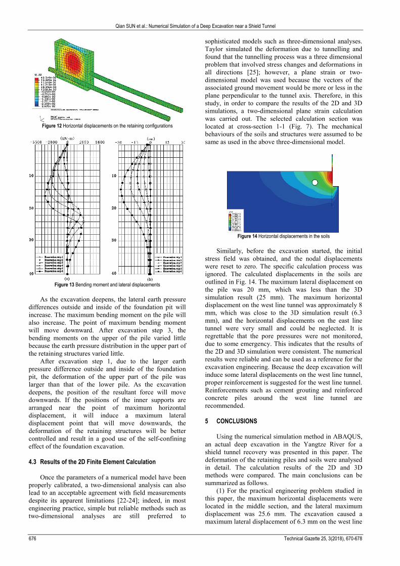
Figure 12 Horizontal displacements on the retaining configurations
Figure 13 Bending moment and lateral displacements
As the excavation deepens, the lateral earth pressure
differences outside and inside of the foundation pit will increase. The maximum bending moment on the pile will also increase. The point of maximum bending moment will move downward. After excavation step 3, the bending moments on the upper of the pile varied little because the earth pressure distribution in the upper part of the retaining structures varied little.
After excavation step 1, due to the larger earth pressure difference outside and inside of the foundation pit, the deformation of the upper part of the pile was larger than that of the lower pile. As the excavation deepens, the position of the resultant force will move downwards. If the positions of the inner supports are arranged near the point of maximum horizontal displacement, it will induce a maximum lateral displacement point that will move downwards, the deformation of the retaining structures will be better controlled and result in a good use of the self-confining effect of the foundation excavation. 4.3 Results of the 2D Finite Element Calculation
Once the parameters of a numerical model have been
properly calibrated, a two-dimensional analysis can also lead to an acceptable agreement with field measurements despite its apparent limitations [22-24]; indeed, in most engineering practice, simple but reliable methods such as two-dimensional analyses are still preferred to
sophisticated models such as three-dimensional analyses. Taylor simulated the deformation due to tunnelling and found that the tunnelling process was a three dimensional problem that involved stress changes and deformations in all directions [25]; however, a plane strain or two-dimensional model was used because the vectors of the associated ground movement would be more or less in the plane perpendicular to the tunnel axis. Therefore, in this study, in order to compare the results of the 2D and 3D simulations, a two-dimensional plane strain calculation was carried out. The selected calculation section was located at cross-section 1-1 (Fig. 7). The mechanical behaviours of the soils and structures were assumed to be same as used in the above three-dimensional model.
Figure 14 Horizontal displacements in the soils
Similarly, before the excavation started, the initial
stress field was obtained, and the nodal displacements were reset to zero. The specific calculation process was ignored. The calculated displacements in the soils are outlined in Fig. 14. The maximum lateral displacement on the pile was 20 mm, which was less than the 3D simulation result (25 mm). The maximum horizontal displacement on the west line tunnel was approximately 8 mm, which was close to the 3D simulation result (6.3 mm), and the horizontal displacements on the east line tunnel were very small and could be neglected. It is regrettable that the pore pressures were not monitored, due to some emergency. This indicates that the results of the 2D and 3D simulation were consistent. The numerical results were reliable and can be used as a reference for the excavation engineering. Because the deep excavation will induce some lateral displacements on the west line tunnel, proper reinforcement is suggested for the west line tunnel. Reinforcements such as cement grouting and reinforced concrete piles around the west line tunnel are recommended. 5 CONCLUSIONS
Using the numerical simulation method in ABAQUS,
an actual deep excavation in the Yangtze River for a shield tunnel recovery was presented in this paper. The deformation of the retaining piles and soils were analysed in detail. The calculation results of the 2D and 3D methods were compared. The main conclusions can be summarized as follows.
(1) For the practical engineering problem studied in this paper, the maximum horizontal displacements were located in the middle section, and the lateral maximum displacement was 25.6 mm. The excavation caused a maximum lateral displacement of 6.3 mm on the west line

Qian SUN et al.: Numerical Simulation of a Deep Excavation near a Shield Tunnel
Tehnički vjesnik 25, 3(2018), 670-678 677
tunnel, but the lateral displacements on the east line tunnel were very small.
(2) As the excavation deepened, the excavation caused the position of the resultant force to move downward. If the positions of the inner supports were arranged near the point of maximum horizontal displacement, the maximum lateral displacement point moved downward, and the deformation of the retaining structures could be better controlled, resulting in a good use of the self-confining effect of the foundation excavation.
(3) As the excavation deepened, the lateral earth pressure difference increased, and the maximum bending moment on the pile also increased. The position of the maximum bending moment moved downward, and the earth pressure distribution in the upper part of the retaining structures varied little.
(4) For this excavation engineering case, the calculation results from the two-dimensional and three-dimensional analyses were consistent. Because the deep excavation will induce some lateral displacement on the west line tunnel, proper reinforcement is suggested for the west line tunnel.
(5) The results indicate that the numerical methods very well described the relationship between the loading and deformation. Numerical simulations are useful in practical engineering applications.
ACKNOWLEDGEMENTS
This study was financially supported by the doctoral
fund of the Chinese Education Ministry and the Nature Science Foundation of Jiangsu Province, China (Grant Nos. 20130091110020 and BE2015675). 6 REFERENCES [1] Jung, H. S., Choi, J. M., Chun, B. S., Park, J. S., & Lee, Y.
J. (2011). Causes of reduction in shield TBM performance - a case study in Seoul. Tunnelling Underground Space Technology, 26(3), 453-461. https://doi.org/10.1016/j.tust.2011.01.001
[2] Kavvadas, M. J. (2005). Monitoring ground deformation in tunnelling: current practice in transportation tunnels. Engineering Geology, 79(1-2), 93-113. https://doi.org/10.1016/j.enggeo.2004.10.011
[3] Tóth, Á., Gong, Q. M., & Zhao, J. (2013). Case studies of TBM tunnelling performance in rock-soil interface mixed ground. Tunnelling underground space technology, 38(9), 140-150. https://doi.org/10.1016/j.tust.2013.06.001
[4] Li, W. B. (2015). Long-term continuous in-situ monitoring of tunnel lining surface temperature in cold region and its application. International journal of heat and technology, 33(2), 39-44. https://doi.org/10.18280/ijht.330206
[5] Liu, X. S. & Liu, S. W. (2012). Study on deformation characteristics of deep foundation excavation in soft-soil and the response of different retaining configurations. Geotech GeolEng, 30(2), 313-329. https://doi.org/10.1007/s10706-011-9470-5
[6] Xu, B. T., Yan, C. H., & Xu, S. (2013). Analysis of the bedding landslide due to the presence of the weak intercalated layer in the limestone. Environmental Earth Sciences, 70(6), 2817-2825. https://doi.org/10.1007/s12665-013-2341-z
[7] Xu, B. T. & Wang, Y. Y. (2015). Stability analysis of the Lingshan gold mine tailings dam under conditions of a
raised dam height. Bulletin of Engineering Geology and the Environment, 74(1), 151-161. https://doi.org/10.1007/s10064-014-0602-z
[8] Jiang, H. J. (2015). Study on statistical characteristics of deep displacement of monitoring data for soil slope. Environmental and earth sciences research journal, 2(4), 11-16. http://dx.doi.org/10.18280/eesrj.020403
[9] Zhang, Z. G. & Huang, M. S. (2014). Geotechnical influence on existing subway tunnels induced by multiline tunnelling in Shanghai soft soil. Computers and Geotechnics, 56(3), 121-132. https://doi.org/10.1016/j.compgeo.2013.11.008
[10] Wang, J. X., Feng, B., & Liu, Y. (2012). Controlling subsidence caused by de-watering in a deep foundation pit. Bulletin of Engineering Geology and Environment, 71, 545-555. https://doi.org/10.1007/s10064-012-0420-0
[11] Wang, J. X., Huang, T. R., Hu, J., Wu, L., & Li, G. (2014). Field experiments and numerical simulations of whirlpool foundation pit dewatering. Environ Earth Science, 71(7), 3245-3257. https://doi.org/10.1007/s12665-013-2981-z
[12] Abaqus/Explicit User’s Manual, version 6.11. Dassault Syste’mesSimulia Corporation. Providence, Rhode Island. 2011.
[13] Wang, X. R., Ren, G. L., & Zhang, J. X. (2018). Numerical simulation and optimization analysis of thermal balance of heavy oil box-type substation louver arrangement. Mathematical Modelling of Engineering Problems, 5(1), 21-26. https://doi.org/10.18280/mmep.050103
[14] Zhang, J. Z. & Zhou, X. P. (2017). Time-dependent jamming mechanism for Single-Shield TBM tunneling in squeezing rock. Tunnelling & Underground Space Technology, 69, 209-222. https://doi.org/10.1016/j.tust.2017.06.020
[15] Liao, W. T. & Deng, X. Y. (2017). Numerical simulation of pressure relief gas flow under mining conditions. International Journal of Heat and Technology, 35(4), 1061-1064. https://doi.org/10.18280/ijht.350443
[16] Gui, M. W. & Chen, S. L. (2013). Estimation of transverse ground surface settlement induced by DOT shield tunnelling. Tunnelling and Underground Space Technology, 33(1), 119-130. https://doi.org/10.1016/j.tust.2012.08.003
[17] Reddy, J. S. K. (2017). A novel subject-object model of consciousness. NeuroQuantology, 15(1), 79-85. https://doi.org/10.14704/nq.2017.15.1.977
[18] Tiwari, R., Chakraborty, T., & Matsagar, V. (2016). Dynamic Analysis of a Twin Tunnel in Soil Subjected to Internal Blast Loading. Indian Geotechnical Journal, 56(4), 1-12. https://doi.org/10.1007/s40098-016-0179-5
[19] Yang, Y. Y. & Li, H. A. (2012). Failure mechanism of large-diameter shield tunnels and its effects on ground surface settlements. Journal of Central South University, 19(10), 2958-2965. https://doi.org/10.1007/s11771-012-1364-z
[20] Higgins, W., Chakraborty, T., & Basu, D. (2012). A high strain-rate constitutive model for sand and its application in finite element analysis of tunnels subjected to blast. Int J Numer Anal Methods Geomech, 37(15), 2590-2610. https://doi.org/10.1002/nag.2153
[21] Brinkgreve, R. B. J. (2004). Plaxis 2D Version 8-User’s Manual and Scientific Manual. A. A. Balkema, Rotterdam, The Netherlands.
[22] Gioda, G. & Swoboda, G. (1999). Developments and applications of the numerical analysis of tunnels in continuous media. International Journal for Numerical and Analytical Methods in Geomechanics, 23(13), 1393-1405. https://doi.org/10.1002/(SICI)1096-9853(199911)23:13
[23] Dai, Y., Zhu, X., & Chen, L. S. (2016). A mechanical-hydraulic virtual prototype co-simulation model for a

Qian SUN et al.: Numerical Simulation of a Deep Excavation near a Shield Tunnel
678 Technical Gazette 25, 3(2018), 670-678
seabed remotely operated vehicle. International Journal of Simulation Modelling, 15(3), 532-541. https://doi.org.10.2507/IJSIMM15(3)CO11
[24] Dai, Y., Chen, L. S., Zhu, X., & Liu, H. (2016). Modelling and simulation of a mining machine excavating seabed massive sulfide deposits. International Journal of Simulation Modelling, 15(2), 377-387. https://doi.org/10.2507/IJSIMM15(2)CO10
[25] Taylor, R. N. (1998). Modeling of tunnel behavior. Proceedings of Institution of Civil Engineers Geotechnical Engineering, 127-132. https://doi.org/10.1680/igeng.1998.30467
Contact information:
Qian SUN School of Earth Science and Engineering, Nanjing University, Nanjing 210093, China Nanjing University of Science & Technology, ZiJin College, Nanjing 210046, China E-mail: [email protected]
Changhong YAN (Corresponding author) School of Earth Science and Engineering, Nanjing University, Nanjing 210093, China E-mail: [email protected]
Jianfei QIU Jiangsu Changshu Electric Power Company Limited, Changshu 215500, China E-mail: [email protected]
Baotian XU School of Earth Science and Engineering, Nanjing University, Nanjing 210093, China E-mail: [email protected]
Bu XU Jiangsu Changshu Electric Power Company Limited, Changshu 215500, China E-mail: [email protected]
Junqiang SHA Jiangsu Xingyuan Electric Construction Supervision CO. LTD, Nanjing 210093, China E-mail: [email protected]