
Numerical Investigations of Unsteady Flow in a Centrifugal Pump ...

Numerical Simulation of A Numerical Simulation of A Centrifugal PumpCentrifugal Pump
CheahCheah Kean WeeKean Wee, A/Prof. T.S. Lee and A/P S.H , A/Prof. T.S. Lee and A/P S.H WinotoWinotoDept. of Mechanical EngineeringDept. of Mechanical Engineering

9/27/20069/27/2006Numerical Simulation of a Numerical Simulation of a
Centrifugal PumpCentrifugal Pump 22
Presentation Outlines:Presentation Outlines:
I.I. ObjectiveObjective
II.II. Introduction / BackgroundIntroduction / Background
III.III. Modeling and Numerical TechniquesModeling and Numerical Techniques
IV.IV. Results and DiscussionsResults and Discussions
V.V. ConclusionsConclusions

9/27/20069/27/2006Numerical Simulation of a Numerical Simulation of a
Centrifugal PumpCentrifugal Pump 33
Objective:Objective:To simulate the complex internal flow in a To simulate the complex internal flow in a centrifugal pump impeller with six twisted centrifugal pump impeller with six twisted bladesblades
To visualize the swirling flow at impeller eyeTo visualize the swirling flow at impeller eye
To visualize unsteady flow due impellerTo visualize unsteady flow due impeller--volute volute interaction at design and offinteraction at design and off--design conditiondesign condition
To investigate pressure loading of impellerTo investigate pressure loading of impeller

9/27/20069/27/2006Numerical Simulation of a Numerical Simulation of a
Centrifugal PumpCentrifugal Pump 44
Introduction / Background:Introduction / Background:
Pump Assembly in present study:Pump Assembly in present study:Bended Suction SectionBended Suction SectionSix twisted blade impeller Six twisted blade impeller
d2 = 356mm impeller outlet diameterd2 = 356mm impeller outlet diameterb2 = 46.8mm impeller outlet widthb2 = 46.8mm impeller outlet width
Volute CasingVolute Casing
The flow pattern inside a centrifugal pump is very complex, threThe flow pattern inside a centrifugal pump is very complex, three dimensional e dimensional and often associated recirculation flow at inlet and exit, flow and often associated recirculation flow at inlet and exit, flow separation, separation, cavitations, and so on.cavitations, and so on.The curvature of the blades and the rotational system has great The curvature of the blades and the rotational system has great influenced on influenced on the flow field. the flow field. Traditional method to design the centrifugal pump mainly based oTraditional method to design the centrifugal pump mainly based on steadyn steady--state theory, empirical correlation, combination of model testinstate theory, empirical correlation, combination of model testing and g and engineering experienceengineering experienceHowever, to further improve the pump performance for design and However, to further improve the pump performance for design and offoff--design design operating conditions it will become extremely difficult. operating conditions it will become extremely difficult. This is because complex flow field such as boundary layer separaThis is because complex flow field such as boundary layer separation, vortex tion, vortex dynamics, interactions between the impeller and diffuser are difdynamics, interactions between the impeller and diffuser are difficult to ficult to control due to the rotating and stationary components. control due to the rotating and stationary components.

9/27/20069/27/2006Numerical Simulation of a Numerical Simulation of a
Centrifugal PumpCentrifugal Pump 55
Modeling & Numerical Modeling & Numerical Techniques:Techniques:
Model Generation:Model Generation:3D CAD modeling of impeller, volute as converted IGES 3D CAD modeling of impeller, volute as converted IGES format in format in WorkBenchWorkBenchDefined 2D regions in Workbench CFXDefined 2D regions in Workbench CFX--mesh such as inlet, mesh such as inlet, outlet and solid wallsoutlet and solid wallsDefined Meshing parameters in Workbench, elements Defined Meshing parameters in Workbench, elements edge size, local mesh density, inflation layer thickness edge size, local mesh density, inflation layer thickness etcetc……Export Workbench meshed model to CFX 5.7.1 for physics Export Workbench meshed model to CFX 5.7.1 for physics

Meshed Models:Meshed Models:
Volute CAD Geometry Meshed Volute Model
Meshed Impeller ModelImpeller CAD Geometry

9/27/20069/27/2006Numerical Simulation of a Numerical Simulation of a
Centrifugal PumpCentrifugal Pump 77
PrePre--processing in CFX:processing in CFX:Meshed models are imported into CFX for physics setMeshed models are imported into CFX for physics set--up:up:
Computational DomainsComputational DomainsIntake Intake ---- StationaryStationaryImpeller Impeller ---- Rotating 1450 rpmRotating 1450 rpmVolute Volute ---- StationaryStationaryAll with static reference pressure 1 All with static reference pressure 1 atmatm
Boundary Conditions: Boundary Conditions: Inlet Inlet –– Mass Flow RateMass Flow RateOutlet Outlet ---- Mass Flow RateMass Flow RateFrozen Rotor/Stator model for steadyFrozen Rotor/Stator model for steady--state simulationstate simulationGeneral Grid Interfaces (GGI) to connect dissimilar meshes and mGeneral Grid Interfaces (GGI) to connect dissimilar meshes and multiulti--domains/frames of reference domains/frames of reference
Turbulence ModelTurbulence ModelStandard Standard κκ--εε turbulence modelturbulence modelScalable wallScalable wall--functionsfunctions
Solver ControlSolver ControlConvergence Criteria Convergence Criteria –– RMS 1.0ERMS 1.0E--44TimeTime--step step –– AutomaticAutomatic

9/27/20069/27/2006Numerical Simulation of a Numerical Simulation of a
Centrifugal PumpCentrifugal Pump 88
PrePre--processing in CFX:processing in CFX:

9/27/20069/27/2006Numerical Simulation of a Numerical Simulation of a
Centrifugal PumpCentrifugal Pump 99
Solver Run & Convergence:Solver Run & Convergence:Example of Residual & Convergence Curve:

9/27/20069/27/2006Numerical Simulation of a Numerical Simulation of a
Centrifugal PumpCentrifugal Pump 1010
Results and Discussions:Results and Discussions:Pump Characteristics Curve:Pump Characteristics Curve:
Centrifugal Pump H-Q Curve
0.00
0.02
0.04
0.06
0.08
0.10
0.12
0.14
0.000 0.005 0.010 0.015 0.020 0.025 0.030 0.035
Flow Coefficient,
Hea
d C
oeffi
cien
t,
ExperimentNumerical

Velocity Vector at Inlet:Velocity Vector at Inlet:
Separation flow observed at intake Separation flow observed at intake top wall regiontop wall regionSwirling flow developed at impeller Swirling flow developed at impeller eyeeye

9/27/20069/27/2006Numerical Simulation of a Numerical Simulation of a
Centrifugal PumpCentrifugal Pump 1212
Swirling Flow at Impeller Eye:Swirling Flow at Impeller Eye:

Velocity Vector Inside Impeller:Velocity Vector Inside Impeller:At design point, the impeller passage flow is very smooth and weAt design point, the impeller passage flow is very smooth and wellll--guided guided except at the leading edge. except at the leading edge. Leading Separation:Leading Separation:
flow coming in from the eye of impeller is being diverted into tflow coming in from the eye of impeller is being diverted into the he bladeblade--toto--blade passage blade passage

9/27/20069/27/2006Numerical Simulation of a Numerical Simulation of a
Centrifugal PumpCentrifugal Pump 1414
Velocity Vector Inside Impeller:Velocity Vector Inside Impeller:
9/27/20069/27/2006Numerical Simulation of a Numerical Simulation of a
Centrifugal PumpCentrifugal Pump 1515
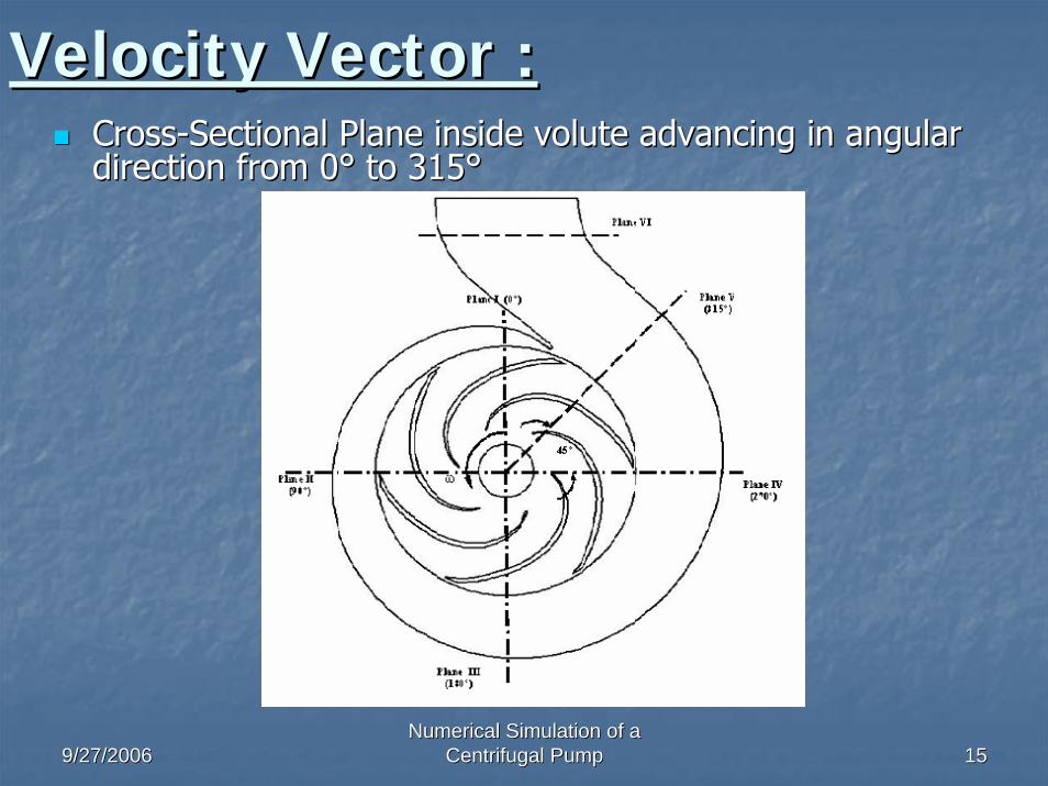
Velocity Vector :Velocity Vector :CrossCross--Sectional Plane inside volute advancing in angular Sectional Plane inside volute advancing in angular direction from 0direction from 0°° to 315to 315°°

Velocity Vector Inside Volute:Velocity Vector Inside Volute:
Plane IV
Shroud
Hub
Plane V Plane VI
Plane I Plane II
Plane III
Shroud
Hub

StreamStream--Line Inside Volute:Line Inside Volute:
Plane VI Plane V Plane VI
Shroud
Hub
Plane IPlane II
Plane III
Shroud
Hub

9/27/20069/27/2006Numerical Simulation of a Numerical Simulation of a
Centrifugal PumpCentrifugal Pump 1818
Vortex FormationVortex Formation--Plane II (90Plane II (90°°))::

9/27/20069/27/2006Numerical Simulation of a Numerical Simulation of a
Centrifugal PumpCentrifugal Pump 1919
Vortex Formation Vortex Formation –– Plane V(315Plane V(315°°))::

Pressure Distribution:Pressure Distribution:Pressure fluctuation due impeller blade trailing edge and volutePressure fluctuation due impeller blade trailing edge and volute tongue interaction:tongue interaction:

Impeller Pressure Distribution:Impeller Pressure Distribution:Pressure Distribution of Pressure and Suction on the Impeller BlPressure Distribution of Pressure and Suction on the Impeller Blade:ade:

9/27/20069/27/2006Numerical Simulation of a Numerical Simulation of a
Centrifugal PumpCentrifugal Pump 2222
Conclusion:Conclusion:With the use of numerical simulationWith the use of numerical simulation ::
The complex internal flow field of a centrifugal pump has been The complex internal flow field of a centrifugal pump has been investigated and investigated and compared with experimental data over the wide flow rangecompared with experimental data over the wide flow rangePredicted head and efficiency between numerical results and expePredicted head and efficiency between numerical results and experiment data show a riment data show a good tendency.good tendency.Swirling flow is observed at the inlet section and causing unsteSwirling flow is observed at the inlet section and causing unsteady flow in impeller eyeady flow in impeller eyeAt design point, the internal flow or velocity vector is very smAt design point, the internal flow or velocity vector is very smooth along the curvature ooth along the curvature along the blades with a weak recirculation at the inlet suction/along the blades with a weak recirculation at the inlet suction/shroud cornershroud cornerLeading edge separation has been observed due to nonLeading edge separation has been observed due to non--tangential inflow conditionstangential inflow conditionsTwin vortices observed inside the volute casing after the dischaTwin vortices observed inside the volute casing after the discharged jet from impeller rged jet from impeller hitting volute wall. hitting volute wall. The pressure increase gradually along the streamThe pressure increase gradually along the stream--wise direction. wise direction. Pressure fluctuation is observed due to trailing edge and volutePressure fluctuation is observed due to trailing edge and volute tongue interactionstongue interactions
With the advanced visualization capability of numerical With the advanced visualization capability of numerical simulation, unseen and hard to model flow phenomenon in simulation, unseen and hard to model flow phenomenon in turbomachineryturbomachinery experiment become a reality in digital rendering experiment become a reality in digital rendering


![The influence of blade outlet angle on the performance of centrifugal pump … · 2020-03-05 · on centrifugal pump performance. Zhang et al. [12] promoted a new numerical hydraulic](https://static.fdocuments.in/doc/165x107/5ea5858178b0254c92765417/the-influence-of-blade-outlet-angle-on-the-performance-of-centrifugal-pump-2020-03-05.jpg)

