Numerical Simulation and Analytical Models for Thin Film ...
6
NUMERICAL SIMULATION AND ANALYTICAL MODELS FOR THIN FILM CDTE LAYERS DEPOSITED BY AN INLINE AP-MOCVD PROCESS Wu Y., Yang X.*, Barrioz V., Rigby S., Huang X. *Author for correspondence Department of Chemical and Environmental Engineering, University of Nottingham Ningbo, Ningbo, 315100, P.R. China, E-mail: [email protected] ABSTRACT The metalorganic chemical vapour deposition (MOCVD) as an attractive method for depositing CdTe and other group II-VI compound thin films has been widely used for fabrication of optoelectronic devices, including photovoltaic solar cells. The thin film deposition of CdTe layer on a substrate with dimethylcadmium (DMCd) and diisopropyltelluride (DIPTe) as precursors has been investigated both numerically and experimentally using an inline reactor. The present work mainly focuses on two aspects of the inline AP-MOCVD process: (1) effects of key deposition parameters such as the substrate temperature T s , the deposition profile, the film thickness distribution and material utilisation on the pyrolysis of CdTe using the dynamic mode (moving substrate) in the simulation; (2) optimisation of the process conditions using static mode (stationary substrate). Both two-dimension (2D) and three-dimension (3D) computational fluid dynamics (CFD) modelling simulations were conducted to simulate the deposition process. Two modelling modes were trialled in the present work, one with the 2D simulation and optimisation of process conditions being conducted by adopting the dynamic mode and the other with 3D simulation but adopting the static mode. The use of dynamic mode in the CFD modelling for CdTe thin film MOCVD was found to be more suitable for approximation of the actual deposition process. The predicted thin film growth rates are consistent with those obtained from the deposition experiments. INTRODUCTION Cadmium telluride (CdTe) is one of the best recognised materials for fabrication of thin film solar cells [1] while the metalorganic chemical vapour deposition (MOCVD) which can be used for deposition of CdTe has attracted a lot of attention due to its advantages of producing high structural quality CdTe thin film layer over a large area substrate and its great commercial value [2]. Although MOCVD has become a relatively mature technology for CdTe thin film deposition and the existing capability of the process control has brought the MOCVD to a reliable thin film preparation [3], the mechanisms of the deposition of thin film CdTe layer by an in-line AP- MOCVD reactor process is still not well understood. The aim of this study is to apply CFD modelling to the simulation and optimisation of the deposition processes using the in-line AP- MOCVD process. Several previously reported studies using CFD modelling in the open literature have demonstrated that the MOCVD processes can be well predicted [4-7] because the use of CFD is not only adequate for prediction of the CdTe growth rates but also convenient for optimisation of the deposition process. Two-dimensional (2D) numerical simulations for MOCVD processes based on CFD modelling approach were well documented in many previous studies. Kuhn et al. [8] applied the 2D simulation for the prediction of the deposition in a horizontal MOCVD reactor. Similarly, Tena-Zaera et al. [9] also used a 2D model in the simulation of CdTe deposition using a horizontal reactor by considering the coupling of heat transfer, mass transport and the species chemistry. However, these simulation results lack the support from the experimental validation. There are a few of studies based on three- dimensional (3D) CFD modelling for prediction of CdTe thin film deposition using MOCVD process. Liu et al. [10,11] and McDaniel et al. [12,13] employed the boundary-layer model coupling the kinetic of chemical reactions in a tubular reactor for prediction of the deposition rates. To date, the studies on the use of CFD modelling for prediction of the deposition and fluid dynamics behaviours in the MOCVD processes are still limited, especially when the surface chemical reaction chemistry is concerned. In contrast to the studies on CFD modelling of the CdTe MOCVD process, the researches focusing on the analysis of material performance and development of CdTe growth using the MOCVD technique through experiments have been reported [14-17]. It is necessary to explore the use of CFD modelling to simulate the real deposition process, in particular the modelling being extended to the three-dimension problems with considering the reaction chemistry. In spite of the above mentioned studies on CdTe thin film growth, there are still many difficulties remaining in the practical simulations of the deposition process using CFD modelling approach. One big limitation is how to approximate and simplify the complicated multistep chemical reactions occurring on the substrate surface. For the CdTe deposition processes, there exist a significant inconsistency for the pre- exponential factor and the activation energy for description of 12th International Conference on Heat Transfer, Fluid Mechanics and Thermodynamics 905
Transcript of Numerical Simulation and Analytical Models for Thin Film ...

NUMERICAL SIMULATION AND ANALYTICAL MODELS FOR THIN FILM CDTE
LAYERS DEPOSITED BY AN INLINE AP-MOCVD PROCESS
Wu Y., Yang X.*, Barrioz V., Rigby S., Huang X.
*Author for correspondence
Department of Chemical and Environmental Engineering,
University of Nottingham Ningbo,
Ningbo, 315100,
P.R. China,
E-mail: [email protected]
ABSTRACT
The metalorganic chemical vapour deposition (MOCVD) as
an attractive method for depositing CdTe and other group II-VI
compound thin films has been widely used for fabrication of
optoelectronic devices, including photovoltaic solar cells. The
thin film deposition of CdTe layer on a substrate with
dimethylcadmium (DMCd) and diisopropyltelluride (DIPTe) as
precursors has been investigated both numerically and
experimentally using an inline reactor. The present work
mainly focuses on two aspects of the inline AP-MOCVD
process: (1) effects of key deposition parameters such as the
substrate temperature Ts, the deposition profile, the film
thickness distribution and material utilisation on the pyrolysis
of CdTe using the dynamic mode (moving substrate) in the
simulation; (2) optimisation of the process conditions using
static mode (stationary substrate). Both two-dimension (2D)
and three-dimension (3D) computational fluid dynamics (CFD)
modelling simulations were conducted to simulate the
deposition process. Two modelling modes were trialled in the
present work, one with the 2D simulation and optimisation of
process conditions being conducted by adopting the dynamic
mode and the other with 3D simulation but adopting the static
mode. The use of dynamic mode in the CFD modelling for
CdTe thin film MOCVD was found to be more suitable for
approximation of the actual deposition process. The predicted
thin film growth rates are consistent with those obtained from
the deposition experiments.
INTRODUCTION Cadmium telluride (CdTe) is one of the best recognised
materials for fabrication of thin film solar cells [1] while the
metalorganic chemical vapour deposition (MOCVD) which can
be used for deposition of CdTe has attracted a lot of attention
due to its advantages of producing high structural quality CdTe
thin film layer over a large area substrate and its great
commercial value [2]. Although MOCVD has become a
relatively mature technology for CdTe thin film deposition and
the existing capability of the process control has brought the
MOCVD to a reliable thin film preparation [3], the mechanisms
of the deposition of thin film CdTe layer by an in-line AP-
MOCVD reactor process is still not well understood. The aim
of this study is to apply CFD modelling to the simulation and
optimisation of the deposition processes using the in-line AP-
MOCVD process. Several previously reported studies using
CFD modelling in the open literature have demonstrated that
the MOCVD processes can be well predicted [4-7] because the
use of CFD is not only adequate for prediction of the CdTe
growth rates but also convenient for optimisation of the
deposition process.
Two-dimensional (2D) numerical simulations for MOCVD
processes based on CFD modelling approach were well
documented in many previous studies. Kuhn et al. [8] applied
the 2D simulation for the prediction of the deposition in a
horizontal MOCVD reactor. Similarly, Tena-Zaera et al. [9]
also used a 2D model in the simulation of CdTe deposition
using a horizontal reactor by considering the coupling of heat
transfer, mass transport and the species chemistry. However,
these simulation results lack the support from the experimental
validation. There are a few of studies based on three-
dimensional (3D) CFD modelling for prediction of CdTe thin
film deposition using MOCVD process. Liu et al. [10,11] and
McDaniel et al. [12,13] employed the boundary-layer model
coupling the kinetic of chemical reactions in a tubular reactor
for prediction of the deposition rates. To date, the studies on the
use of CFD modelling for prediction of the deposition and fluid
dynamics behaviours in the MOCVD processes are still limited,
especially when the surface chemical reaction chemistry is
concerned. In contrast to the studies on CFD modelling of the
CdTe MOCVD process, the researches focusing on the analysis
of material performance and development of CdTe growth
using the MOCVD technique through experiments have been
reported [14-17]. It is necessary to explore the use of CFD
modelling to simulate the real deposition process, in particular
the modelling being extended to the three-dimension problems
with considering the reaction chemistry.
In spite of the above mentioned studies on CdTe thin film
growth, there are still many difficulties remaining in the
practical simulations of the deposition process using CFD
modelling approach. One big limitation is how to approximate
and simplify the complicated multistep chemical reactions
occurring on the substrate surface. For the CdTe deposition
processes, there exist a significant inconsistency for the pre-
exponential factor and the activation energy for description of
12th International Conference on Heat Transfer, Fluid Mechanics and Thermodynamics
905

the involved chemical reactions when using the well-known
Arrhenius equation. In order to better fit the experimental
results, the parameters of kinetics of surface chemical reaction
have to be modified. It has been generally accepted that the
sequential reactions involved in the CdTe deposition process
can be replaced by adopting a proposed global surface reaction
in the CFD modelling as far as the major characteristics of the
reactions can be reflected. The simplified global reaction
assumed in the CFD modelling was reported in our previous
study [19, 24].
The unavoidable numerical diffusion arising from the CFD
modelling is strongly associated with the mesh size and mesh
quality and this significantly affect the accuracy of the
prediction of the deposition rate which is also influenced by the
approximations introduced in the mathematical models,
boundary conditions and the numerical discretisation scheme
employed in the simulation. The aim of this study is to reveal
the effect of mesh size and mesh qualities used in the CFD
modelling on the prediction of the CdTe thin film deposition
rates on a substrate by varying the temperature on the substrate
surface. The CdTe thin film was deposited through the usage of
an inline deposition process with a novel MOCVD reactor.
Dimethylcadmium (DMCd) and diisopropyltelluride (DIPTe)
were used as the precursors, injected from a showerhead into
the reaction chamber. CFD modelling simulates the case where
a substrate (75×50×3 mm3) was placed in the reactor and was
deposited. The simulations were run in two modes: dynamic
and static modes [20, 21]. All simulations were conducted by
using CFD code-ANSYS Fluent [22]. For improving the
prediction to match the experimental data obtained from the
real inline reactor process, the adoption of a sliding mesh for
moving susceptor was proposed. To the best knowledge of the
authors, there is no reported study on adopting this kind of
model into the CFD modelling for prediction of CdTe thin film
deposition process although this method has been widely used
for stirred reactor simulations in mixing [23].
This paper is organised into three parts, description of the
details of the modelling process, numerical modelling and
discussion on simulation results and conclusions reached from
the current study.
NOMENCLATURE A [s-1] Pre-exponential factor
cp [J/(kg·K)] Heat capacity
Cprecursor [kg/m3] Concentration of precursor
Di [m2/s] Binary diffusion coefficient of species i
DiT [m2/s] Thermal mass diffusion coefficient of species i
Ea [kcal/mol] Activation energy
g [m/s2] Gravity acceleration
GR [µm/min] Growth rate of surface reaction Hi [J/mol] Enthalpy of species i
K [-] Number of chemical species
N [-] Number of chemical species
P [pascal] Operating pressure of reactor
q [J/m2·s] Heat flux vector
R [J/(mol·K)] Universal gas constant
Rrf [mol/(m·s)] Rate of forward chemical reaction
Rrb [mol/(m·s)] Rate of backward chemical reaction
R’ [-] By-products of surface reaction
T [K] Temperature Ts [K] Substrate temperature
V [m/s] Velocity vector of gas flow
Yi [-] Mass fraction of species i
Special characters
Β [-] Unitless factor Σ [Å] Collision diameter
ε/k [K] Characteristic potential
Τ [kg/m3] Density of the gas flow Z [Pa] Viscous stress tensor
Subscripts AP Atmospheric pressure
G Gas
I Species i s Solid
NUMERICAL MODEL DESCRIPTION An in-line MOCVD reactor which was self-designed in
CSER OpTic has been used as a referenced geometric model
employed in the CFD simulations. The reactor details can be
found in [20]. For the growth of CdTe layer, the DMCd and
DIPTe are transported by carrier gas – hydrogen (H2) and are
introduced into reactor through the injection head. The entire
MOCVD reactor is sealed by the nitrogen (N2) - filled between
the outside of the reactor and the system - to seal the tolerable
gap between the outside walls from the inevitable manufactured
errors; and also to cool the hot reactor despite the water cooling
that is adopted. CdTe growth was deposited on the heated
substrate with the size of 75×50 mm2; the substrate can be set
as stationary or moving according to the situations. The
temperature of the substrate is assumed to be uniformly
distributed, varying from 355 to 455 °C. The total flow rate is
set to be 0.5 l/min with the II/VI ratio remaining at 0.55. An
atmospheric pressure condition was assumed in the simulations.
A simplified geometric model based on the actual MOCVD
reactor and the mesh imposed for the set-up is shown in Figure
1. The entire computational domain contains approximately
310,000 cells.
(a)
(b)
Figure 1 The mesh set-up used in CFD modelling: (a) 3D
overview (b) the front view
12th International Conference on Heat Transfer, Fluid Mechanics and Thermodynamics
906

Since the deposition process is strongly influenced by the
temperature gradient and boundary layer formed on the
substrate, a fine mesh in the vicinity of the substrate has been
imposed. To ensure that the skewness of the mesh is as small as
possible, hexahedral structured cells were used throughout the
computational domain. Considering the grid resolutions, the
mesh size was chosen in such a way that the size is gradually
refined towards the bottom wall of the reactor, reducing the
numerical diffusion arising from the simulation.
On the other hand, the sliding mesh method was used for
the 2D simplification model. Accordingly, the reactor is
defined into two regions, consisting of the reactor chamber and
the moving susceptor (Figure 2). The reactor chamber is kept to be stationary while the moving substrate slides along the
bottom of the chamber by specifying an interface between the
two mesh set-ups.
Figure 2 Treatment of the moving substrate and the mesh
set-up (the sliding mesh)
The MOCVD is a complex process which involves various
transport phenomena. In both numerical models, the flow in the
reactor was assumed to be steady and the carrier gas was
assumed to obey the ideal gas law. The Reynolds number based
on the hydraulic diameter of the reactor falls into a range of 1 to
100, indicating that the gas flow in the reactor can be regarded
as laminar flow. No-slip boundary condition was applied to the
walls of the reactor. Steady state is considered for the static
mode simulation, because the growth rate of thin film is very
slow compared to the velocity of gases. However, for the
dynamic mode simulation, time dependent simulation has been
adopted to assess the effect of the deposit cumulated on the thin
film thickness growth. The governing equations which describe
the CdTe deposition process are listed in Table 1.
Table 1 Governing equations in the reactor Name Equations
Conservation
of mass
∇ ∙ (𝜌𝒗) = 0 (1)
Conservation
of momentum
𝛻 ∙ (𝜌𝒗𝒗) + 𝛻𝑃 = −[𝛻 ∙ 𝝉] + 𝜌𝒈 (2)
Conservation
of energy
𝑐𝑝
𝜕𝜌𝑇
𝜕𝑡+ 𝑐𝑝∇ ∙ (𝜌𝒗𝑇) = ∇ ∙ 𝒒 +
𝐷𝑃
𝐷𝑡− 𝝉: ∇𝒗
− ∑ ∑ 𝐻𝑖𝒗𝑖𝑟(𝑅𝑟𝑓
− 𝑅𝑟𝑏)
𝐾
𝑗=1
𝑁
𝑖=1
(3)
Species
transport ∇ ∙ (𝜌𝒗𝑌𝑖) + ∇ ∙ (−𝜌𝐷𝑖∇𝑌𝑖 − 𝐷𝑖
𝑇∇𝑇
𝑇) + [∇ ∙ 𝝉]
= 𝑅𝑖
(4)
In addition, the reaction chemistry of the CdTe deposition
involves multistep reactions but an overall surface reaction is
assumed in the present study [24]:
(CH3)2Cd (g) + (C3H7)2Te (g) → CdTe (s) + R’ (g)
where R’ indicates all the products and by-products which
yielded from the surface reaction. The detailed mechanism has
been simplified by assuming a rapid surface reaction in the
simulation process. Since the carrier gas flow has been assumed
as ideal gas flow, the mass diffusivities and thermal
diffusivities of the gas mixture can be determined using the
kinetic theory. The rate constant of the surface reaction can be
expressed by the Arrhenius equation [25]:
𝑘 = 𝐴𝑇𝛽exp (−𝐸𝑎/𝑅𝑇) (5)
where A is the pre-exponential factor, T is the temperature, β is
temperature index, Ea is the activation energy and R is the
universal gas constant. Because the pre-exponential factor A
and the activation energy Ea change significantly and there are
not censors data available in the open literature, we have
employed a set of data (assuming the combination of the two
precursors in the overall surface reaction), obtained from fitting
the experimental data.
RESULTS AND DISCUSSION
Static mode simulation
In order to evaluate the effect of substrate temperature on
the CdTe growth rate, the substrate temperature was varied
from 355 ºC to 455 °C, which covers two dominant regions,
mass transport limited and kinetic limited. As can be seen from
equation (5), kinetic limited process is significantly affected by
the temperature. In the simulations, the activation energy has
been estimated to be equal to 40 kcal/mol based on the fitting
from the experimental data. II/VI ratio was kept to be equal to
0.55.
The grid sensitivity studies were first applied on two
different grids in 2D model. To investigate the effect of grid
size, the simulations were also conducted by employing the
same operation conditions as the 2D model in 3D modelling
case. The second order upwind differencing scheme and the
SIMPLEC algorithm were used in the simulations. As can be
seen from Figure 3, the predicted CdTe mass deposition rates
when employing the hexahedral fine structured grid are in
better agreement with the experimental ones than the use of the
coarse mesh, indicating that the mesh set-up in modelling of the
MOCVD has an impact on the prediction accuracy. This may
12th International Conference on Heat Transfer, Fluid Mechanics and Thermodynamics
907
be explained by the fact that great changes in the velocity and
temperature fields occur throughout the boundary layer in the
neighbouring of the substrate surface. Any numerical diffusion
arising from the simulations may cause errors. Thus, a refined
mesh should be imposed in the vicinity of the substrate surface
in order to capture the fluid dynamics and deposition
behaviours. The relatively coarser mesh has been applied in the
rest of the fluid domain except for the showerhead inlet region
where the diffusion behaviour again affects the prediction of the
flow and deposition behaviours. It seems that the deposition
rate prediction in the kinetic limited regime is more sensitive to
the mesh size than that in mass transport control regime. This
can be seen from the equation (3) for energy conservation since
the contribution from the term to account for the chemical
reaction appearing in the equation is closely associated with the
mesh size for numerical simulation. On the other hand, the mid-
temperature range is limited by mass transfer and the effect of
the mesh size on the predicted CdTe mass deposition rates is
not remarkable.
Figure 3 Predicted CdTe deposition rates versus the substrate
temperature when using both the coarse and fined mesh in 3D
modelling
Dynamic mode simulation
A trial study was conducted in a time-dependent two
dimensional modelling of CdTe thin film deposition by using
the sliding mesh method, coupled with the chemical kinetics.
The simulation was performed by using a time step of 1s and
the total time steps are set to be 420s to accord with the actual
experiments conducted.
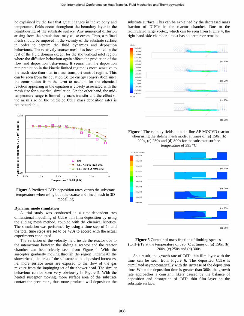
The variation of the velocity field inside the reactor due to
the interactions between the sliding susceptor and the reactor
chamber can been clearly seen from Figure 4. With the
susceptor gradually moving through the region underneath the
showerhead, the area of the substrate to be deposited increases,
i.e. more surface areas are exposed to the flow of the gas
mixture from the impinging jet of the shower head. The similar
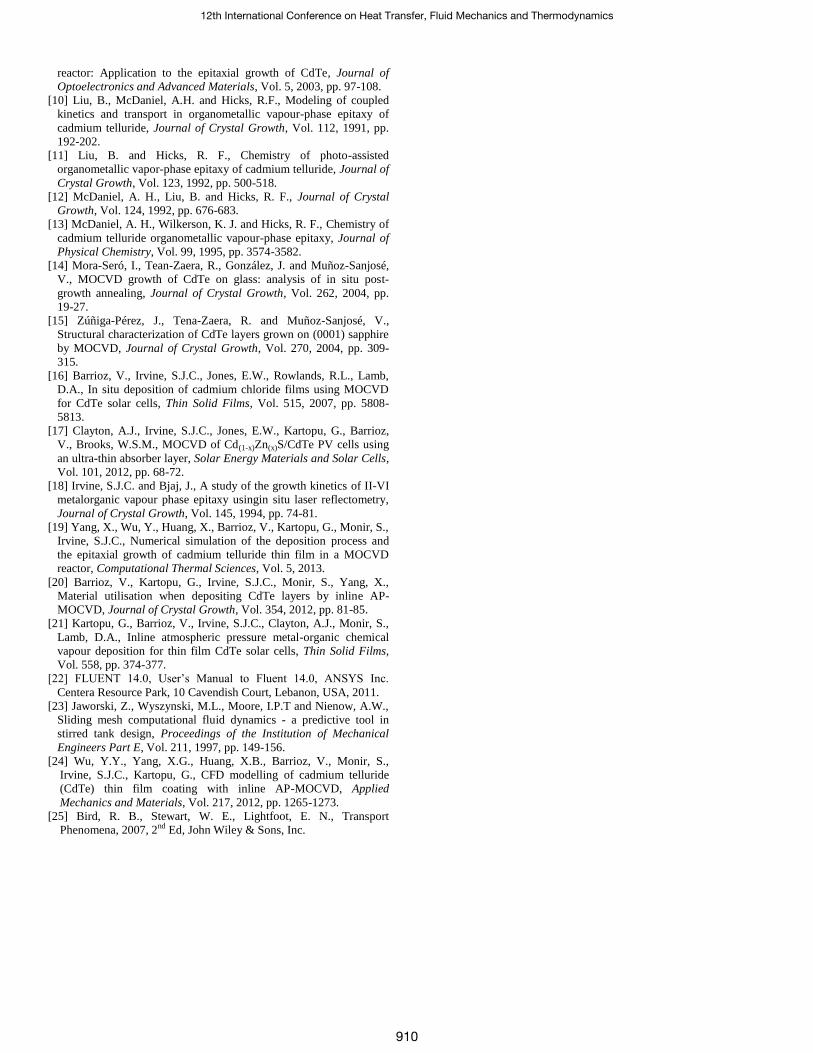
behaviour can be seen very obviously in Figure 5. With the
heated susceptor moving, more surface area of the substrate
contact the precursors, thus more products will deposit on the
substrate surface. This can be explained by the decreased mass
fraction of DIPTe in the reactor chamber. Due to the
recirculated large vortex, which can be seen from Figure 4, the
right-hand-side chamber almost has no precursor remains.
Figure 4 The velocity fields in the in-line AP-MOCVD reactor
when using the sliding mesh model at times of (a) 150s, (b)
200s, (c) 250s and (d) 300s for the substrate surface
temperature of 395 °C
Figure 5 Contour of mass fraction of limiting species-
(C3H7)2Te at the temperature of 395 °C at times of (a) 150s, (b)
200s, (c) 250s and (d) 300s
As a result, the growth rate of CdTe thin film layer with the
time can be seen from Figure 6. The deposited CdTe is
cumulated asymptomatically with the increase of the deposition
time. When the deposition time is greater than 360s, the growth
rate approaches a constant, likely caused by the balance of
deposition and desorption of CdTe thin film layer on the
substrate surface.
(a) 150s
(b) 200s
(c) 250s
(d) 300s
(a) 150s
(b) 200s
(c) 250s
(d) 300s
12th International Conference on Heat Transfer, Fluid Mechanics and Thermodynamics
908

Figure 6 Time dependant variation of the CdTe growth rate
predicted using the sliding mesh model
Figure 7 Comparisons between the CFD modelling on thin film
growth rates and the experiment observations for different
substrate temperatures.
Figure 7 shows the comparisons between the predicted thin
film growth rates using the CFD modelling and the
experimental data at different substrate temperatures. It can be
seen from the figure that the simulated time dependent CdTe
thin film growth rates are in a favourable agreement with the
experimental ones. However, the CFD modelling results do not
match up the experimental data in the region of the transition at
the temperatures around 405 °C. This is likely caused by the
under estimation of the diffusion coefficients Di, because Di is
strongly depend on the species’ properties, such as Lennard-
Jones parameter which estimated based on kinetic theory [25],
thus it is possible to be underestimation and this remains to be
determined from the empirical correlations. Inaddition, Di is
also strongly affected by the temperature ( 2/3T ). According
to equation (4), both kinetic and mass transport terms affect the
deposition rate. Also, based on equation (5), it is known that the
kinetic term is proportional to exp (-1/T). Therefore, if the
deposition process starts to be limited by mass transport at the
temperature around 405 °C, numerical analysis results may not
show a sudden change the same as the experimental results.
Further study on this regard is required.
CONCLUSION The results obtained using the time-dependent CFD
modelling clearly indicates that the grid size and quality
significantly affect the predicted CdTe thin film deposition
rates, especially for the kinetic limited regime. The effect of the
mesh size and quality has to be considered carefully in the CFD
modelling of the MOCVD process.
The use of sliding mesh method has shown to be successful
for simulation of CdTe thin film layer deposition in an inline
MOCVD reactor. It has been demonstrated that the use of this
method may capture the time-dependant deposition behaviour
and reflect the effect of the moving substrate. Further testing
and validation of this method may be necessary. The sliding
mesh model may be valuable for optimisation of the deposition
process, which may be used for the design of new MOCVD
reactors.
ACKNOWLEDGEMENT Yiyi Wu wishes to thank the financial support from the
University of Nottingham Ningbo through an UNNC PhD
scholarship. Thanks are also gone to the technical support from
the research group in Centre of Solar Energy Research (CSER),
OpTIC Glyndŵr, St Asaph Business Park, St Asaph, UK.
REFERENCES
[1] Ferekides, C.S., Marinskiy, D., Viswanathan, V., Tetali, B.,
Palekis, V., Selvaraj, P. and Morel, D.L., High efficiency CSS CdTe
solar cells, Thin Solid Films, Vol. 361-362, 2000, pp. 520-526.
[2] Woods, L. and Meyers, P., Atmospheric pressure chemical vapour
deposition and jet vapour deposition of CdTe for high efficiency thin
film PV devices, National Renewable Energy Laboratory, 2002.
[3] Creighton, J.R. and Ho, P., Chemical Vapor Deposition, ASM
International, 2001.
[4] Im, I., Sugiyama, M., Shimogaki, Y. and Nakano, Y., A numerical
study on heat transfer and film growth rate of InP and GaAs
MOCVD process, Journal of Crystal Growth, Vol. 276, 2005, pp.
431-438.
[5] Mazumder, S. and Lowry, S.A., The importance of predicting rate-
limited growth for accurate modelling of commercial MOCVD
reactors, Journal of Crystal Growth, Vol. 224, 2001, pp. 165-174.
[6] Han, J.H. and Yoon, D.Y., 3D CFD forchemical transport profiles
in a rotating dish CVD reactor, 3D Research Center and Springer,
2010.
[7] Yang, L.Q., Chen, Z.M., Zhang, J.H. and Li A.G., Transport
phenomena in a novel large MOCVD reactor for epitaxial growth of
GaN thin films, IEEE transactions on semiconductor manufacturing,
Vol. 25, No. 1, 2012.
[8] Kuhn, W.S., Angermeier, D., Druilhe, R., Gebhardt, W. and
Triboulet, R., Analysis of the CVD in a horizontal reactor, II. The
epitaxy of CdTe, Journal of Crystal Growth, Vol. 183, 1998, pp.
535-544.
[9] Tena-Zaera, R., Mora-Sero, I., Martinez-Tomas, C. and Munoz-
Sanjose, V., Numerical study of the growth conditions in a MOCVD
12th International Conference on Heat Transfer, Fluid Mechanics and Thermodynamics
909
reactor: Application to the epitaxial growth of CdTe, Journal of
Optoelectronics and Advanced Materials, Vol. 5, 2003, pp. 97-108.
[10] Liu, B., McDaniel, A.H. and Hicks, R.F., Modeling of coupled
kinetics and transport in organometallic vapour-phase epitaxy of
cadmium telluride, Journal of Crystal Growth, Vol. 112, 1991, pp.
192-202.
[11] Liu, B. and Hicks, R. F., Chemistry of photo-assisted
organometallic vapor-phase epitaxy of cadmium telluride, Journal of
Crystal Growth, Vol. 123, 1992, pp. 500-518.
[12] McDaniel, A. H., Liu, B. and Hicks, R. F., Journal of Crystal
Growth, Vol. 124, 1992, pp. 676-683.
[13] McDaniel, A. H., Wilkerson, K. J. and Hicks, R. F., Chemistry of
cadmium telluride organometallic vapour-phase epitaxy, Journal of
Physical Chemistry, Vol. 99, 1995, pp. 3574-3582.
[14] Mora-Seró, I., Tean-Zaera, R., González, J. and Muñoz-Sanjosé,
V., MOCVD growth of CdTe on glass: analysis of in situ post-
growth annealing, Journal of Crystal Growth, Vol. 262, 2004, pp.
19-27.
[15] Zúñiga-Pérez, J., Tena-Zaera, R. and Muñoz-Sanjosé, V.,
Structural characterization of CdTe layers grown on (0001) sapphire
by MOCVD, Journal of Crystal Growth, Vol. 270, 2004, pp. 309-
315.
[16] Barrioz, V., Irvine, S.J.C., Jones, E.W., Rowlands, R.L., Lamb,
D.A., In situ deposition of cadmium chloride films using MOCVD
for CdTe solar cells, Thin Solid Films, Vol. 515, 2007, pp. 5808-
5813.
[17] Clayton, A.J., Irvine, S.J.C., Jones, E.W., Kartopu, G., Barrioz,
V., Brooks, W.S.M., MOCVD of Cd(1-x)Zn(x)S/CdTe PV cells using
an ultra-thin absorber layer, Solar Energy Materials and Solar Cells,
Vol. 101, 2012, pp. 68-72.
[18] Irvine, S.J.C. and Bjaj, J., A study of the growth kinetics of II-VI
metalorganic vapour phase epitaxy usingin situ laser reflectometry,
Journal of Crystal Growth, Vol. 145, 1994, pp. 74-81.
[19] Yang, X., Wu, Y., Huang, X., Barrioz, V., Kartopu, G., Monir, S.,
Irvine, S.J.C., Numerical simulation of the deposition process and
the epitaxial growth of cadmium telluride thin film in a MOCVD
reactor, Computational Thermal Sciences, Vol. 5, 2013.
[20] Barrioz, V., Kartopu, G., Irvine, S.J.C., Monir, S., Yang, X.,
Material utilisation when depositing CdTe layers by inline AP-
MOCVD, Journal of Crystal Growth, Vol. 354, 2012, pp. 81-85.
[21] Kartopu, G., Barrioz, V., Irvine, S.J.C., Clayton, A.J., Monir, S.,
Lamb, D.A., Inline atmospheric pressure metal-organic chemical
vapour deposition for thin film CdTe solar cells, Thin Solid Films,
Vol. 558, pp. 374-377.
[22] FLUENT 14.0, User’s Manual to Fluent 14.0, ANSYS Inc.
Centera Resource Park, 10 Cavendish Court, Lebanon, USA, 2011.
[23] Jaworski, Z., Wyszynski, M.L., Moore, I.P.T and Nienow, A.W.,
Sliding mesh computational fluid dynamics - a predictive tool in
stirred tank design, Proceedings of the Institution of Mechanical
Engineers Part E, Vol. 211, 1997, pp. 149-156.
[24] Wu, Y.Y., Yang, X.G., Huang, X.B., Barrioz, V., Monir, S.,
Irvine, S.J.C., Kartopu, G., CFD modelling of cadmium telluride
(CdTe) thin film coating with inline AP-MOCVD, Applied
Mechanics and Materials, Vol. 217, 2012, pp. 1265-1273.
[25] Bird, R. B., Stewart, W. E., Lightfoot, E. N., Transport
Phenomena, 2007, 2nd Ed, John Wiley & Sons, Inc.
12th International Conference on Heat Transfer, Fluid Mechanics and Thermodynamics
910