Numerical modelling of shielding gas flow and heat...
8
Numerical modelling of shielding gas flow and heat transfer in laser welding process Alireza Javidi Shirvan 1 , Isabelle Choquet 1 , Håkan Nilsson 2 1 University West, Department of Engineering Science, Trollhättan, Sweden 2 Chalmers University of Technology, Department of Applied Mechanics, Gothenburg, Sweden [email protected] ABSTRACT In the present work a three-dimensional model has been developed to study shielding gas flow and heat transfer in a laser welding process using computational fluid dynam- ics. This investigation was motivated by problems met while using an optical system to track the weld path. The aim of this study was to investigate if the shielding gas flow could disturb the observation area of the optical system. The model combines heat conduction in the solid work piece and thermal flow in the fluid region occupied by the shielding gas. These two regions are coupled through their energy equations so as to allow heat transfer between solid and fluid region. Laser heating was modelled by imposing a volumetric heat source, moving along the welding path. The model was implemented in the open source software OpenFOAM and applied to argon shielding gas and titanium alloy Ti6Al4V base metal. Test cases were done to investigate the shielding gas flow produced by two components: a pipe allowing shielding the melt, and a plate allowing shielding the weld while it cools down. The simulation results con- firmed that these two components do provide an efficient shielding. They also showed that a significant amount of shielding gas flows towards the observation area of the op- tical system intended to track the weld path. This is not desired since it could transport smoke that would disturb the optical signal. The design of the shielding system thus needs to be modified. Keywords: laser welding, shielding gas, volumetric heat source, coupling boundary 1 Introduction This study was motivated by problems met in a man- ufacturing context while welding titanium with a laser welding tool. In this welding process a shielding gas is brought by a pipe above the base metal around the focal point of the laser heat source. The first reason for using a shielding gas is to prevent the molten metal from the harmful effect of the ambient air [1]. The oxy- gen and nitrogen present in the air can cause slag inclusions and brittleness, respectively. Helium, argon and carbon dioxide are the most common shielding gases in welding. Argon is an appropriate option for sensible materials such as aluminium, stainless steel, and titanium [1], since it does not react chemically with welded materials. Argon is the shielding gas used in this study. When welding materials that are highly reactive with oxygen, a shielding gas can also be used to form an additional screen large enough to cover the part of the weld already solidified but not yet cooled. In this study a plate is fixed on the back side of the pipe (see 1
Transcript of Numerical modelling of shielding gas flow and heat...

Numerical modelling of shielding gas flow and heat transfer in laserwelding process
Alireza Javidi Shirvan1, Isabelle Choquet1, Håkan Nilsson2
1University West, Department of Engineering Science, Trollhättan, Sweden2Chalmers University of Technology, Department of Applied Mechanics, Gothenburg, Sweden
ABSTRACT
In the present work a three-dimensional model has been developed to study shieldinggas flow and heat transfer in a laser welding process using computational fluid dynam-ics. This investigation was motivated by problems met while using an optical system totrack the weld path. The aim of this study was to investigate if the shielding gas flowcould disturb the observation area of the optical system. The model combines heatconduction in the solid work piece and thermal flow in the fluid region occupied by theshielding gas. These two regions are coupled through their energy equations so asto allow heat transfer between solid and fluid region. Laser heating was modelled byimposing a volumetric heat source, moving along the welding path. The model wasimplemented in the open source software OpenFOAM and applied to argon shieldinggas and titanium alloy Ti6Al4V base metal. Test cases were done to investigate theshielding gas flow produced by two components: a pipe allowing shielding the melt,and a plate allowing shielding the weld while it cools down. The simulation results con-firmed that these two components do provide an efficient shielding. They also showedthat a significant amount of shielding gas flows towards the observation area of the op-tical system intended to track the weld path. This is not desired since it could transportsmoke that would disturb the optical signal. The design of the shielding system thusneeds to be modified.
Keywords: laser welding, shielding gas, volumetric heat source, coupling boundary
1 Introduction
This study was motivated by problems met in a man-ufacturing context while welding titanium with a laserwelding tool. In this welding process a shielding gasis brought by a pipe above the base metal around thefocal point of the laser heat source. The first reasonfor using a shielding gas is to prevent the molten metalfrom the harmful effect of the ambient air [1]. The oxy-gen and nitrogen present in the air can cause slaginclusions and brittleness, respectively. Helium, argon
and carbon dioxide are the most common shieldinggases in welding. Argon is an appropriate option forsensible materials such as aluminium, stainless steel,and titanium [1], since it does not react chemically withwelded materials. Argon is the shielding gas used inthis study.When welding materials that are highly reactive withoxygen, a shielding gas can also be used to form anadditional screen large enough to cover the part ofthe weld already solidified but not yet cooled. In thisstudy a plate is fixed on the back side of the pipe (see
1

Fig. 1) to form an argon shielding screen coveringthe weld and preventing titanium from oxidizing dur-ing cooling. The welding apparatus is planned to beequipped with an optical system intended to track thewelding path. The optical system must be mounted infront of the welding tool to observe the front area ofthe weld.During welding smoke is emitted. This smoke is a mix-ture of fine particles (fume) and gases produced in theweld. It flows under the combined action of buoyancyforce and the surrounding shielding gas flow. Theproblem motivating this study is that the smoke couldflow through the observation area of the optical sys-tem used to track the weld path, and thereby affectthe accuracy of the path tracking. A better knowledgeof the shielding gas flow was thus needed.
Figure 1: Schematic sketch of the shielding plate forcase 4
Figure 2: shielding pipe for different cases
The present work was done to study the shielding gasflow investigating both the shielding gas injected bythe shielding pipe and the extended shielding screen.As these gas flows are partially hidden by the equip-ment, a convenient way to study them was to per-form simulations using computational fluid dynamics(CFD).Some studies based on CFD [2, 3] have been doneto understand the fluid dynamics of the shielding gasduring laser welding process. Hong et al. [2] consid-ered argon and helium as shielding gas with three dif-ferent ranges of flow rate through a circular pipe withtwo different angles with the work piece. Tani et al. [3]have tested four different types of gas with three differ-ent pipe angles and three different flow rates to studythe influence of each parameter on the behaviour ofthe shielding gas flow. Shuja et al. [4] used air for gasinjection rather than a usual shielding gas, and consid-ered different welding speed. However, the influenceof the plate used to form an extended shielding screenwas not investigated by these authors.The present work, was done using the OpenFOAM-1.6.x OpenSource CFD tool (www.openfoam.com).OpenFOAM is basically a general library of C++classes for numerical simulation of continuum me-chanic problems, and it is mainly used in CFD. Thesimulation model implemented in OpenFOAM com-bines heat conduction in a solid region (the workpiece) and thermal flow in a fluid region (occupied bythe shielding gas). A thermal energy equation is thussolved in the solid region. In the fluid region a largerset of equations including mass, momentum and en-ergy conservation is solved. These two regions arecoupled through their energy equations so as to allowheat transfer between solid and fluid region. This cou-pling is also called conjugate heat transfer. The laseris modelled as a heat source acting locally on the sur-face of the work piece.The model for shielding gas flow and laser heat sourceis discussed in section 2. In section 3, the test casesand numerical settings are given. The first test casesare done for pipes that are not equipped with a plate.The angle between pipe axis and work piece is 60◦.The geometry of the first pipe simulated (see Fig. 2,left) has an end opening normal to the pipe axis but nolateral opening. This configuration cannot be used inpractice, as it would not allow the laser beam to reachthe work piece. This test case was however studied
2
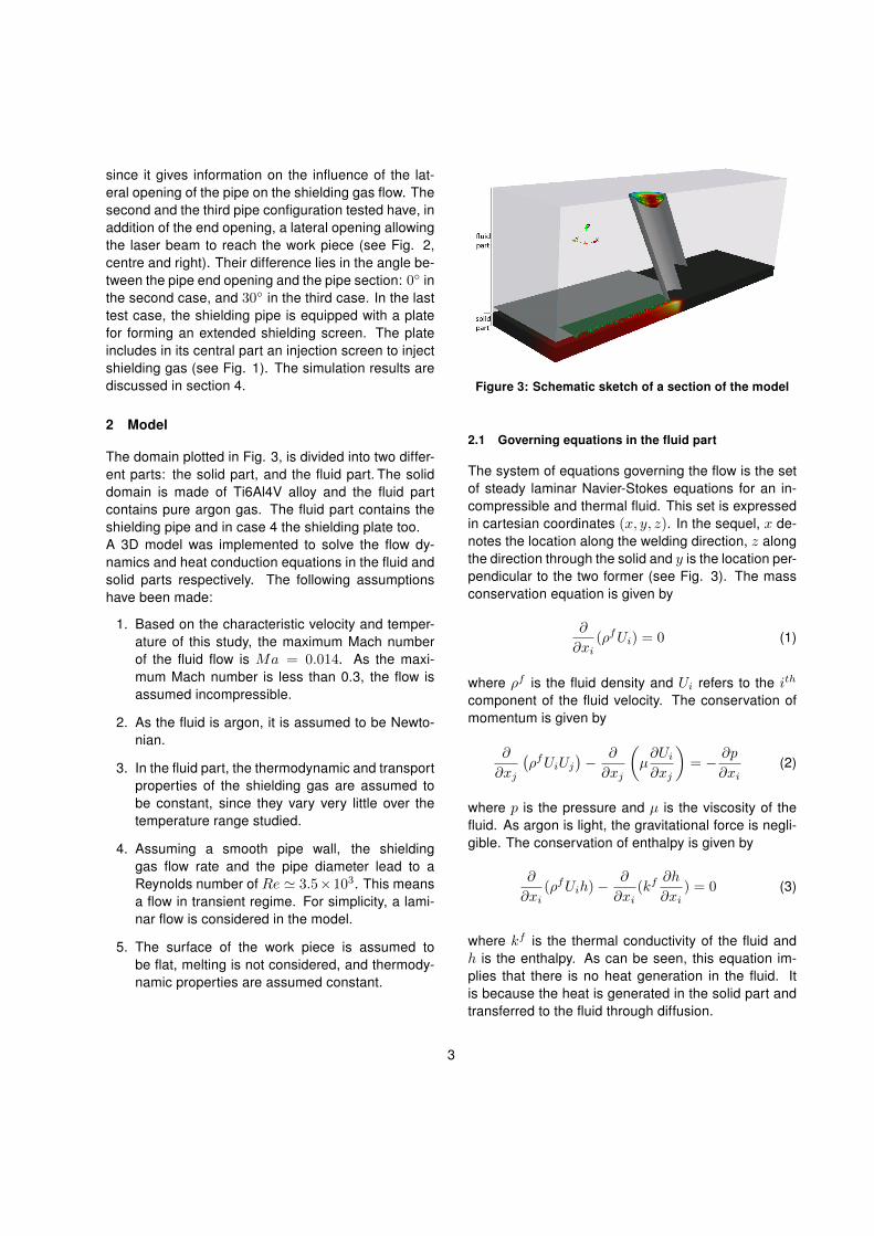
since it gives information on the influence of the lat-eral opening of the pipe on the shielding gas flow. Thesecond and the third pipe configuration tested have, inaddition of the end opening, a lateral opening allowingthe laser beam to reach the work piece (see Fig. 2,centre and right). Their difference lies in the angle be-tween the pipe end opening and the pipe section: 0◦ inthe second case, and 30◦ in the third case. In the lasttest case, the shielding pipe is equipped with a platefor forming an extended shielding screen. The plateincludes in its central part an injection screen to injectshielding gas (see Fig. 1). The simulation results arediscussed in section 4.
2 Model
The domain plotted in Fig. 3, is divided into two differ-ent parts: the solid part, and the fluid part. The soliddomain is made of Ti6Al4V alloy and the fluid partcontains pure argon gas. The fluid part contains theshielding pipe and in case 4 the shielding plate too.A 3D model was implemented to solve the flow dy-namics and heat conduction equations in the fluid andsolid parts respectively. The following assumptionshave been made:
1. Based on the characteristic velocity and temper-ature of this study, the maximum Mach numberof the fluid flow is Ma = 0.014. As the maxi-mum Mach number is less than 0.3, the flow isassumed incompressible.
2. As the fluid is argon, it is assumed to be Newto-nian.
3. In the fluid part, the thermodynamic and transportproperties of the shielding gas are assumed tobe constant, since they vary very little over thetemperature range studied.
4. Assuming a smooth pipe wall, the shieldinggas flow rate and the pipe diameter lead to aReynolds number of Re ≃ 3.5×10³. This meansa flow in transient regime. For simplicity, a lami-nar flow is considered in the model.
5. The surface of the work piece is assumed tobe flat, melting is not considered, and thermody-namic properties are assumed constant.
Figure 3: Schematic sketch of a section of the model
2.1 Governing equations in the fluid part
The system of equations governing the flow is the setof steady laminar Navier-Stokes equations for an in-compressible and thermal fluid. This set is expressedin cartesian coordinates (x, y, z). In the sequel, x de-notes the location along the welding direction, z alongthe direction through the solid and y is the location per-pendicular to the two former (see Fig. 3). The massconservation equation is given by
∂
∂xi(ρfUi) = 0 (1)
where ρf is the fluid density and Ui refers to the ith
component of the fluid velocity. The conservation ofmomentum is given by
∂
∂xj
(ρfUiUj
)− ∂
∂xj
(µ∂Ui
∂xj
)= − ∂p
∂xi(2)
where p is the pressure and µ is the viscosity of thefluid. As argon is light, the gravitational force is negli-gible. The conservation of enthalpy is given by
∂
∂xi(ρfUih)−
∂
∂xi(kf
∂h
∂xi) = 0 (3)
where kf is the thermal conductivity of the fluid andh is the enthalpy. As can be seen, this equation im-plies that there is no heat generation in the fluid. Itis because the heat is generated in the solid part andtransferred to the fluid through diffusion.
3
2.2 Governing equation in the solid part
The governing heat conduction equation accountingfor laser heating can be written as
Uri
∂
∂xi(ρscspT )−
∂
∂xi(Ks ∂T
∂xi) = Qls (4)
where Uri is the ith component of the relative velocity
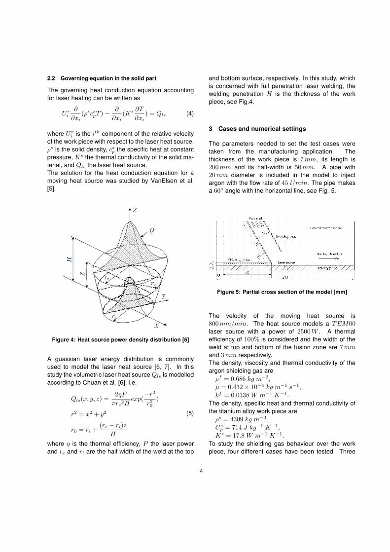
of the work piece with respect to the laser heat source.ρs is the solid density, csp the specific heat at constantpressure, Ks the thermal conductivity of the solid ma-terial, and Qls the laser heat source.The solution for the heat conduction equation for amoving heat source was studied by VanElsen et al.[5].
Figure 4: Heat source power density distribution [6]
A guassian laser energy distribution is commonlyused to model the laser heat source [6, 7]. In thisstudy the volumetric laser heat source Qls is modelledaccording to Chuan et al. [6], i.e.
Qls(x, y, z) =2ηP
πre2Hexp(
−r2
r20)
r2 = x2 + y2
r0 = ri +(re − ri)z
H
(5)
where η is the thermal efficiency, P the laser powerand re and ri are the half width of the weld at the top
and bottom surface, respectively. In this study, whichis concerned with full penetration laser welding, thewelding penetration H is the thickness of the workpiece, see Fig.4.
3 Cases and numerical settings
The parameters needed to set the test cases weretaken from the manufacturing application. Thethickness of the work piece is 7mm, its length is200mm and its half-width is 50mm. A pipe with20mm diameter is included in the model to injectargon with the flow rate of 45 l/min. The pipe makesa 60◦ angle with the horizontal line, see Fig. 5.
Figure 5: Partial cross section of the model [mm]
The velocity of the moving heat source is800mm/min. The heat source models a TEM00laser source with a power of 2500W . A thermalefficiency of 100% is considered and the width of theweld at top and bottom of the fusion zone are 7mmand 3mm respectively.The density, viscosity and thermal conductivity of theargon shielding gas areρf = 0.686 kg m−3,µ = 0.432× 10⁻⁴ kg m−1 s−1,kf = 0.0338 W m−1 K−1.
The density, specific heat and thermal conductivity ofthe titanium alloy work piece areρs = 4309 kg m−3
Csp = 714 J kg−1 K−1,
Ks = 17.8 W m−1 K−1.To study the shielding gas behaviour over the workpiece, four different cases have been tested. Three
4

cases aim at investigating the effect of the shieldingpipe outlet shape on the gas flow without shieldingplate, see Fig.2. The fourth case is inspecting theinfluence of the shielding plate on the gas flow, seeFig.1.Case 1 includes the left pipe of Fig. 2 and no shieldingplate. This first pipe has an end opening normal to thepipe axis but no lateral opening. This configurationcannot be used in practice, as it would not allow thelaser beam to reach the work piece. This test casewas however studied since it gives information onthe influence of the lateral opening of the pipe on theshielding gas flow.As can be seen in Fig. 2 the shielding pipe of case2 is based on case 1 but with the presence of anadditional opening on the wall of the pipe to let thelaser beam reach the base metal (see Fig. 2, centre).The dimension of the opening is 13mm× 20mm.Case 3 differs from case 2 by the shape of the outletof the pipe. (see Fig. 2, right). The angle between thepipe end opening and the pipe section is equal to 30◦
in the third case while it was equal to 0◦ in the formercases.The model in case 4 is implemented with the samefeatures as case 3, supplemented with a shieldingplate. The shielding plate has an injection screenthrough which the gas flows at a rate of 45 l/min tocover the welded part, see Fig.1. The injection screenof the shielding plate has a length of 70mm and anhalf-width of 20mm. The geometry of the model isillustrated by the cross-section in Fig. 5.The meshes of cases 1 to 3 have about 3.3 millioncells. Case 4 has only about 1.4 million cells sincethe region located over the shielding plate and behindthe pipe does not need to be included into thecomputational domain.
3.1 Boundary conditions
Boundary conditions are applied for the fluid part, thesolid part, and the interface between them.
3.1.1 Fluid part
A parabolic velocity distribution is specified at the in-let of the shielding pipe. To achieve the flow rate of45 l/min, a maximum velocity of 4.77 m/s is em-ployed.
In case 4, where the shielding plate is included, an in-let boundary with uniform velocity of 1.9m/s is alsoset at the injection screen to form a shielding screenwith a flow rate of 45 l/min.At the surrounding boundaries of the fluid part (on topand sides), a zero gradient condition is used for thevelocity and the pressure is set to the atmosphericpressure.The inlet temperature of the shielding gas is at roomcondition, that is 300 K. The same temperature con-dition is applied to the fluid boundaries (on top andsides) of the computational domain.It was checked (running calculations with a largercomputational domain domain) that the size of thecomputational domain is large enough to allow usingsuch boundary conditions.
3.1.2 Solid part
In the manufacturing application, cooling water wasflowing into a duct mounted under the work piece.The water inlet temperature was 6◦ C. The details ofthe cooling system were not included in the simula-tion model. The cooling effect was accounted for in asimplified way in the simulation test, assuming a fixedtemperature condition T = 300K at the bottom solidboundary. This value was calculated using standardanalytic models for heat transfer in pipe flow. A zerogradient boundary condition is employed for the tem-perature at the sides of the solid part.
3.1.3 Interface between solid and fluid
At the interface between the solid and fluid regions, acommon no-slip boundary condition is set for the fluidvelocity.Solid and fluid are coupled through their energy equa-tions so as to allow heat transfer between solid andfluid region. The energy equation in the solid regiongoverns the solid temperature, while the energy equa-tion in the fluid region governs the fluid enthalpy. Sotheir coupling is not direct: the direction of the heatflux is first determined. Then, the thermal coupling isdone setting automatically the fixed value or the fixedgradient depending on the direction of the heat flux.This boundary condition, called a conjugation bound-ary for heat flux and temperature, is implemented by asolver so called chtMultiRegionFoam in OpemFOAM1.6x.
5
The open source software, OpenFOAM-1.6.x was em-ployed to run the simulations based on above three-dimensional configurations.
4 Results
4.1 Temperature distribution
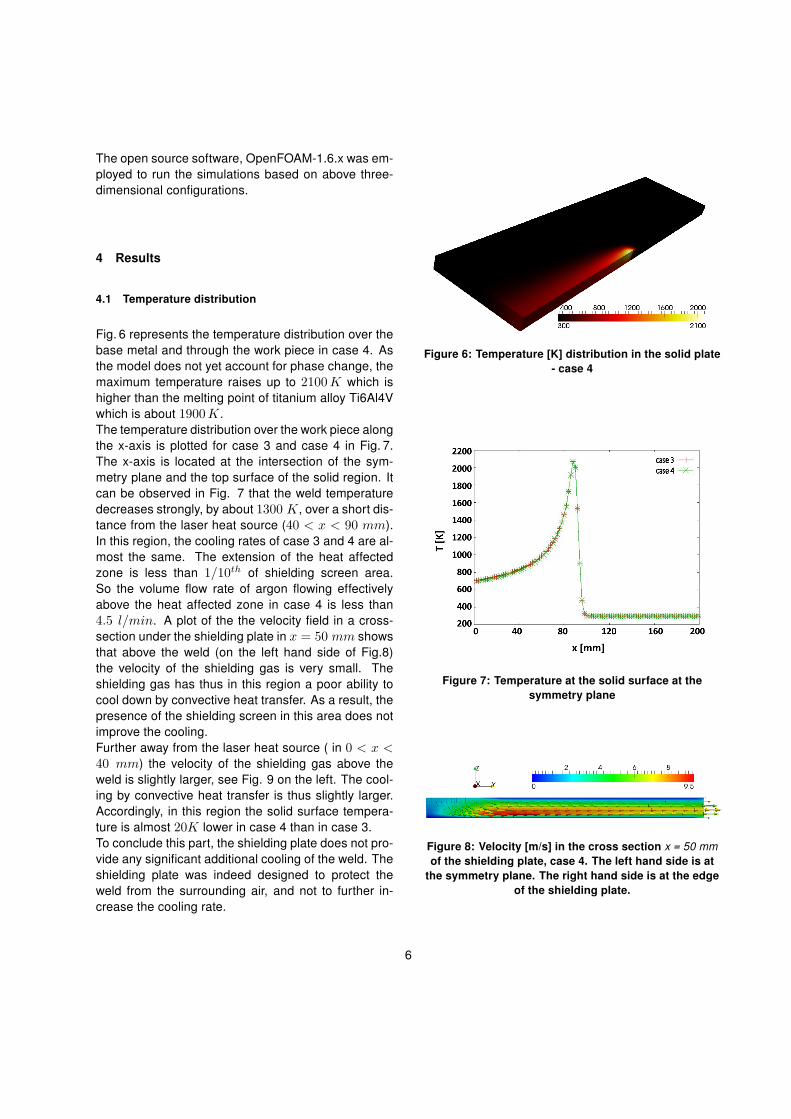
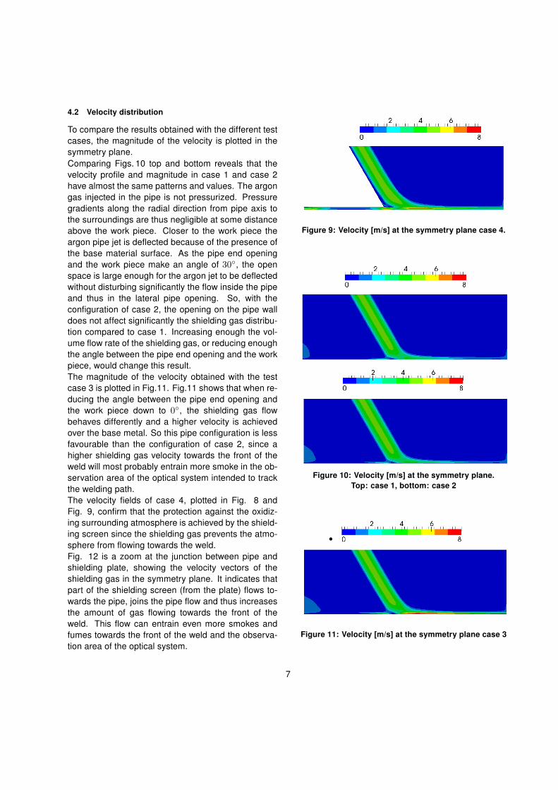
Fig. 6 represents the temperature distribution over thebase metal and through the work piece in case 4. Asthe model does not yet account for phase change, themaximum temperature raises up to 2100K which ishigher than the melting point of titanium alloy Ti6Al4Vwhich is about 1900K.The temperature distribution over the work piece alongthe x-axis is plotted for case 3 and case 4 in Fig. 7.The x-axis is located at the intersection of the sym-metry plane and the top surface of the solid region. Itcan be observed in Fig. 7 that the weld temperaturedecreases strongly, by about 1300 K, over a short dis-tance from the laser heat source (40 < x < 90 mm).In this region, the cooling rates of case 3 and 4 are al-most the same. The extension of the heat affectedzone is less than 1/10th of shielding screen area.So the volume flow rate of argon flowing effectivelyabove the heat affected zone in case 4 is less than4.5 l/min. A plot of the the velocity field in a cross-section under the shielding plate in x = 50 mm showsthat above the weld (on the left hand side of Fig.8)the velocity of the shielding gas is very small. Theshielding gas has thus in this region a poor ability tocool down by convective heat transfer. As a result, thepresence of the shielding screen in this area does notimprove the cooling.Further away from the laser heat source ( in 0 < x <40 mm) the velocity of the shielding gas above theweld is slightly larger, see Fig. 9 on the left. The cool-ing by convective heat transfer is thus slightly larger.Accordingly, in this region the solid surface tempera-ture is almost 20K lower in case 4 than in case 3.To conclude this part, the shielding plate does not pro-vide any significant additional cooling of the weld. Theshielding plate was indeed designed to protect theweld from the surrounding air, and not to further in-crease the cooling rate.
Figure 6: Temperature [K] distribution in the solid plate- case 4
Figure 7: Temperature at the solid surface at thesymmetry plane
Figure 8: Velocity [m/s] in the cross section x = 50 mmof the shielding plate, case 4. The left hand side is at
the symmetry plane. The right hand side is at the edgeof the shielding plate.
6
4.2 Velocity distribution
To compare the results obtained with the different testcases, the magnitude of the velocity is plotted in thesymmetry plane.Comparing Figs. 10 top and bottom reveals that thevelocity profile and magnitude in case 1 and case 2have almost the same patterns and values. The argongas injected in the pipe is not pressurized. Pressuregradients along the radial direction from pipe axis tothe surroundings are thus negligible at some distanceabove the work piece. Closer to the work piece theargon pipe jet is deflected because of the presence ofthe base material surface. As the pipe end openingand the work piece make an angle of 30◦, the openspace is large enough for the argon jet to be deflectedwithout disturbing significantly the flow inside the pipeand thus in the lateral pipe opening. So, with theconfiguration of case 2, the opening on the pipe walldoes not affect significantly the shielding gas distribu-tion compared to case 1. Increasing enough the vol-ume flow rate of the shielding gas, or reducing enoughthe angle between the pipe end opening and the workpiece, would change this result.The magnitude of the velocity obtained with the testcase 3 is plotted in Fig.11. Fig.11 shows that when re-ducing the angle between the pipe end opening andthe work piece down to 0◦, the shielding gas flowbehaves differently and a higher velocity is achievedover the base metal. So this pipe configuration is lessfavourable than the configuration of case 2, since ahigher shielding gas velocity towards the front of theweld will most probably entrain more smoke in the ob-servation area of the optical system intended to trackthe welding path.The velocity fields of case 4, plotted in Fig. 8 andFig. 9, confirm that the protection against the oxidiz-ing surrounding atmosphere is achieved by the shield-ing screen since the shielding gas prevents the atmo-sphere from flowing towards the weld.Fig. 12 is a zoom at the junction between pipe andshielding plate, showing the velocity vectors of theshielding gas in the symmetry plane. It indicates thatpart of the shielding screen (from the plate) flows to-wards the pipe, joins the pipe flow and thus increasesthe amount of gas flowing towards the front of theweld. This flow can entrain even more smokes andfumes towards the front of the weld and the observa-tion area of the optical system.
Figure 9: Velocity [m/s] at the symmetry plane case 4.
Figure 10: Velocity [m/s] at the symmetry plane.Top: case 1, bottom: case 2
Figure 11: Velocity [m/s] at the symmetry plane case 3
7

Figure 12: Zoom of case 4 showing the velocity vectorsin the symmetry plane, at the junction between pipe
and shielding plate.
5 Conclusions
The flow of the laser welding shielding gas over thebase metal with both shielding pipe and shielding platehas been studied. The present results confirm that theshielding plate provides a good protection of the cool-ing weld against the surrounding atmosphere.The shielding screen produced by the plate has a neg-ligible influence on the cooling rate of the weld.However, the design of the shielding pipe and plate(case 4, the case used in practice) is in conflict withthe requirements of the optical system for tracking thewelding path. A larger angle between end pipe open-ing and work piece, as in case 2, leads to lower shield-ing gas velocity towards the front of the weld com-pared to case 3 (and 4), but this is not sufficient toprotect the observation area from the possible entrain-ment of fumes by the shielding gas. Based on case 2,more extended lateral openings on the pipe wall arenot expected to provide any significant improvement.The design of the pipe and plate should thus be mod-ified to deflect differently the shielding gas flow, awayfrom the observation area, while maintaining a propershielding. A solution could be to force a lateral flow ofthe shielding gas by introducing pressure gradients.Checking with CFD that a new design is suited will re-quire a more detailed modelling of the flow, accountingfor turbulence, as the pipe flow is known to be tran-sient (see section 2), and turbulence may also disturb
the observation area of the optical system for trackingthe welding path.
6 References
[1] K.Weman (2003). Welding processes handbook.Woodhead publishing ltd. England.
[2] H.Wang, Y.Shi, S.Gong, A.Duan (2007). Effectof assist gas flow on the gas shielding duringlaser deep penetration welding. Journal of Ma-terial processing Technology. 184, pp. 379-385.
[3] G.Tani, A.Ascari, G.Campana, A.Fortunato(2007). A study on shielding gas contamination inlaser welding of non-ferrous alloys. Applied Sur-face Science. 254, pp. 904-907.
[4] S.Z.Shuja, B.S.Yillbas,(2000). 3-Dimensionalconjugate laser heating of a moving slab. Appliedsurface science. 167, pp. 134-148.
[5] M.Van Elsen, M.Baelmans, P.Mercelis, J.-p.Kruth (2007). Solution for modelling moving heatsource in a semi-infinite medium and applicationsto laser material processing. International Jour-nal of heat and mass transfer. 50, pp. 4872-4882.
[6] L.Chuan, Z.Jianxun, N.Jing (2009). Numericaland Experimental Analysis of Residual Stressesin Full-Penetration Laser Beam Welding ofTi6Al4V Alloy. Rare Metal Materials and Engi-neering. 38, pp. 1317-1320.
[7] K.Abderrazak, W.Kriaa, W.Ben Salem, H.Mhiri,G.Lepalec, M.Autric (2009). Numerical and Ex-perimental studies of molten pool formation dur-ing an interaction of a pulse laser (ND:YAG) witha magnesium alloy. Optics and Laser technology.41, pp. 470-480.
8