NUMERICAL INVESTIGATION OF STROUHAL … INVESTIGATION OF STROUHAL FREQUENCIES OF TWO STAGGERED BLUFF...
6
Excerpt from the Proceedings of the 2013 COMSOL Conference in Bangalore NUMERICAL INVESTIGATION OF STROUHAL FREQUENCIES OF TWO STAGGERED BLUFF BODIES Eswaran M 1 , P. Goyal, Anu Dutta, G.R. Reddy, R. K. Singh and K.K. Vaze Bhabha Atomic Research Centre, Mumbai, India. 1 Corresponding author email: [email protected] ABSTRACT: In this paper, the 2-D unsteady viscous flow around two cylinders is studied by numerical solutions of the unsteady Navier-Stokes equations with a finite element formulation. The results of a numerical investigation of the Strouhal frequencies of two identical, stationary, parallel circular cylinders arranged in staggered configurations is presented in this paper. A simple two cylinder tandem arrangement is validated for a certain range of values of spacing ratio (L/D) with few previously published results. Results of measurements of the Strouhal frequencies of circular cylinders arranged in tandem and in some selected staggered configurations are also presented. In the case of two circular cylinders, the investigation is performed at staggered angles (α) of 10°, 15°, 20° and 25° in the range of L/D =2.0 to 4.0 and Re = 100 to 15000. The findings in this study for two circular cylinders are: (i) critical spacing ratio is simulated successfully and (ii) Lift force and drag force variation for different staggered angle. Keywords: Tandem cylinders; Strouhal frequency; Vortex shedding; Lift and drag force; Wind loads. INTRODUCTION: In engineering, fluid forces and Strouhal numbers are the primary factors considered in the design of multiple slender structures subjected to cross flow, e.g., chimney stacks, tube bundles in heat exchangers, overhead power-line bundles, bridge piers, stays, masts, chemical reaction towers, offshore platforms and adjacent skyscrapers. The simplest arrangement of multiple slender structures is two cylinders in either tandem or side-by-side arrangement. Though the staggered arrangement is perhaps the configuration most commonly found in engineering applications, numerous investigations on the flows past two circular cylinders in side-by-side and tandem arrangements have been performed, but investigations pertaining to two staggered cylinders are relatively few, particularly investigation of the vortex-shedding processes in terms of the Strouhal frequencies of two staggered cylinders. As has been revealed in the previous studies, for a small value of L/D (see Fig. 1 for definitions of symbols), i.e., when the downstream cylinder is fully or partially submerged into the upstream cylinder wake, the two cylinders behave like a single body and the frequencies of vortex shedding behind the two cylinders are the same. For an intermediate value of L/D, at which narrower and wider wakes are formed behind the upstream and downstream cylinders, respectively, the frequencies of vortex shedding behind the upstream and downstream cylinders are of a higher and lower magnitude, respectively. For a higher value of L/D, i.e., when each cylinder sheds vortices independently, the frequency of vortex shedding behind each cylinder is the same as that in the case of a single, isolated cylinder. Flow around two tandem cylinders of identical diameters is in general classified into three major regimes [1, 2]: (i) the extended-body regime (L/D < 0.7), where the two cylinders are so close to each other that the free shear layers detached from the front cylinder overshoot the rear one, and the flow in the gap of the cylinders is stagnant; (ii) the reattachment regime (L/D = 0.7 to 3.5), where the shear layers separated from the front cylinder reattach on the rear cylinder and the flow in the gap is still insignificant; (iii) the co-shedding regime (L/D > 3.5), where the shear layers roll up alternately in the gap between the cylinders and thus the flow in the gap is significant. From the fundamental point of view, aerodynamic interference between two closely separated cylinders may
-
Upload
phungthuan -
Category
Documents
-
view
220 -
download
1
Transcript of NUMERICAL INVESTIGATION OF STROUHAL … INVESTIGATION OF STROUHAL FREQUENCIES OF TWO STAGGERED BLUFF...

Excerpt from the Proceedings of the 2013 COMSOL Conference in Bangalore
NUMERICAL INVESTIGATION OF STROUHAL FREQUENCIES OF TWO
STAGGERED BLUFF BODIES
Eswaran M1, P. Goyal, Anu Dutta, G.R. Reddy, R. K. Singh and K.K. Vaze Bhabha Atomic Research Centre, Mumbai, India. 1Corresponding author email: [email protected]
ABSTRACT:
In this paper, the 2-D unsteady viscous flow around two cylinders is studied by numerical solutions of the unsteady Navier-Stokes equations with a finite element formulation. The results of a numerical investigation of the Strouhal frequencies of two identical, stationary, parallel circular cylinders arranged in staggered configurations is presented in this paper. A simple two cylinder tandem arrangement is validated for a certain range of values of spacing ratio (L/D) with few previously published results. Results of measurements of the Strouhal frequencies of circular cylinders arranged in tandem and in some selected staggered configurations are also presented. In the case of two circular cylinders, the investigation is performed at staggered angles (α) of 10°, 15°, 20° and 25° in the range of L/D =2.0 to 4.0 and Re = 100 to 15000. The findings in this study for two circular cylinders are: (i) critical spacing ratio is simulated successfully and (ii) Lift force and drag force variation for different staggered angle.
Keywords: Tandem cylinders; Strouhal frequency; Vortex shedding; Lift and drag force; Wind loads.
INTRODUCTION: In engineering, fluid forces and Strouhal numbers are the primary factors considered in the
design of multiple slender structures subjected to cross flow, e.g., chimney stacks, tube bundles in heat exchangers, overhead power-line bundles, bridge piers, stays, masts, chemical reaction towers, offshore platforms and adjacent skyscrapers. The simplest arrangement of multiple slender structures is two cylinders in either tandem or side-by-side arrangement. Though the staggered arrangement is perhaps the configuration most commonly found in engineering applications, numerous investigations on the flows past two circular cylinders in side-by-side and tandem arrangements have been performed, but investigations pertaining to two staggered cylinders are relatively few, particularly investigation of the vortex-shedding processes in terms of the Strouhal frequencies of two staggered cylinders. As has been revealed in the previous studies, for a small value of L/D (see Fig. 1 for definitions of symbols), i.e., when the downstream cylinder is fully or partially submerged into the upstream cylinder wake, the two cylinders behave like a single body and the frequencies of vortex shedding behind the two cylinders are the same. For an intermediate value of L/D, at which narrower and wider wakes are formed behind the upstream and downstream cylinders, respectively, the frequencies of vortex shedding behind the upstream and downstream cylinders are of a higher and lower magnitude, respectively. For a higher value of L/D, i.e., when each cylinder sheds vortices independently, the frequency of vortex shedding behind each cylinder is the same as that in the case of a single, isolated cylinder.
Flow around two tandem cylinders of identical diameters is in general classified into three major regimes [1, 2]: (i) the extended-body regime (L/D < 0.7), where the two cylinders are so close to each other that the free shear layers detached from the front cylinder overshoot the rear one, and the flow in the gap of the cylinders is stagnant; (ii) the reattachment regime (L/D = 0.7 to 3.5), where the shear layers separated from the front cylinder reattach on the rear cylinder and the flow in the gap is still insignificant; (iii) the co-shedding regime (L/D > 3.5), where the shear layers roll up alternately in the gap between the cylinders and thus the flow in the gap is significant. From the fundamental point of view, aerodynamic interference between two closely separated cylinders may

Excerpt from the Proceedings of the 2013 COMSOL Conference in Bangalore
give rise to flow separation, reattachment, vortex impingement, recirculation and quasi-periodic vortices, involving most generic flow features associated with multiple structures. Thus, flow around two tandem cylinders provides a good model to understand the physics of flow around multiple cylindrical structures. NUMERICAL METHODOLOGY: (i) Governing equations Based on the Navier-stokes time averaged equations and using Bousssinesq approximation for Renolds stresses, differential equations governing viscous turbulent flow field can be written as
0)(
u
div
t (1)
xeff fx
pgradudivudiv
t
u
)()(
)(
u (2)
yeff fy
pgradvdivvdiv
t
v
)()(
)(
u (3)
where is the fluid density, eff the effective viscosity, u the mean flow velocity field, p the
pressure and u, v are the mean components of flow field in the x and y directions, respectively. The terms fx , fy denote body forces for the unit volume of fluid. The turbulence is modelled by the two
equation k model which is easily implement and has a wide application in engineering problems. Thus, the turbulence of flow field is expressed in turbulence kinetic energy (k) and dissipation rate ( ), using following equations,
kk Pgradkdivkudiv
t
k)()(
)( (4)
kcP
kcgraddivudiv
tk
2
21)()()(
(5)
tefft
kC
;
2
(6)
where ktk / and /t are diffusion coefficients for k and , respectively, Pk is the
production rate by turbulent shear stresses, is the molecular viscosity and t is the turbulent
viscosity. The terms k (turbulent Prandtl number) and (the turbulent Schmidt number ), C1, C2
are experimental constants of the model. For this model, C1, C2, k and , and C have the values
of 1.44, 1.92, 1, 1.3, 0.09 respectively. The standard k model along with Boussinesq equation, performs well for the broad range of engineering problems, however in the problems which include unbalanced effects , etc., finally this model reaches to responses which are over diffused, i.e., the
t values predicted by this model will be large.
in this study, the fluid is assumed incompressible. As there is no free surface, the body forces can be ignored (fx=0, fy =0). Equations (1) through (3) is for laminar flow, plus Equations (4) through (6s ) for turbulent flow are governing the flow field which will be solved numerically. (ii) Computational domain and boundary conditions Two cylinders of equal diameter are placed in a 35D x 20D rectangular domain, in which the center of upstream cylinder is located 10D from the inlet boundary and center of the downstream cylinders is placed at a distance of 25D from the outlet boundary, where D denotes the cylinder diameter.

Excerpt from the Proceedings of the 2013 COMSOL Conference in Bangalore
Fig.1 Notation for staggered configuration.
At the inlet, the Dirchlet boundary conditions are applied (u=U, v=0, k=0.03U2 and lk 005.02 ,
where U is the free stream velocity, and l is the radius of computational domain of flow).The pressure is prescribed at a point at the inlet. At the outlet, the Neumann-type conditions are
employed ( 0 xu , 0 xv , 0 xk and . No slip boundary condition is applied at the
boundary of a fixed cylinder , i.e., velocity components on the boundaries zero ( 0u , 0v ). The top and bottom boundaries of the computational domain are considered as symmetry boundary to negate the propagation wall effects inside the domain over the time period. (iii) Grid generation and discretization In this study, non uniform staggered Cartesian grid is used and the enclosed area of two cylinders is refined with respect to other areas of the flow field. Boundary layers have also been created around the solid boundary. In such a grid, the velocity components (u and v) are calculated for the points located on the main control volume surfaces, i.e., the staggered points, while pressure, kinetic energy and dissipation rate of turbulent energy (p, k and are calculated for the points located on the main grid. The flow close to a solid wall is for a turbulent flow, is very different compared to the free stream. This means that the assumptions used to derive the k model are not valid close to walls. While it is possible to modify the k model so that it describes the flow in wall regions such as extended k and RNG k models. Instead, analytical expressions are used to describe the flow at the walls. These expressions are known as wall functions. The distance yw is automatically computed so that ,
/wtw yy .
where kCt41
is the friction velocity, which becomes 11.06. This corresponds to the distance
from the wall where the logarithmic layer meets the viscous sub-layer (or to some extent would meet if there was not a buffer layer in between). Temporal discretization is performed based on second order implicit method which causes much less damping and is thereby more accurate.
Fig.2 Grid arrangement Fig.3 Boundary layers around the
cylinder. Results and discussion: The dimensionless flow parameters are defined as follows,
DU
FC D
D 2
2
,
DU
FC L
L 2
2
where FL and FD denote life and drag forces, respectively. Dimensionless flow parameters are also given by

Excerpt from the Proceedings of the 2013 COMSOL Conference in Bangalore
D
tUT
U
DfSt
UD v ,,Re
where Re is the Reynolds number, St is the Strouhal number, T is the dimensionless time, is the
fluid viscosity, D is the cylinder diameter, t is the time at each time step and fv is the frequency of vertex shedding which can be calculated from the oscillating frequency of lift force. Case 1: Flow past two tandem cylinders at Re =200 and α =0˚. In order to better understand the flow characteristics and wake interference between two tandem cylinders, initially, flow past a stationary circular cylinder is solved for laminar and turbulent cases. And then, simple tandem cylinder arrangement cases were analysed and compared with Zdravkovich et al. (1987) and Alam and Zhou (2007) results. The present results are very closely matching with their experimental results and numerical results. After the validation, the different staggered angles are studied in detail. Downstream cylinder is submerged into the upstream cylinder wake for the lower L/D ratio. The negative drag will disappear, while increasing the staggered angle α. Here the Fig. 4 and 5 show the tandem arrangement with α =0˚ and L/D =3.0 drag and α =15˚ and L/D =2.0 drag respectively.
Fig. 4 Streamline plot for tandem cylinder α =0˚
and L/D =4.0 Fig. 5 velocity contour plot for tandem cylinder α =0˚
and L/D =4.0 Strouhal number is an significant feature of fluid which has a strong dependence on both Reynolds number and spacing. This non-dimensional number, specify how cylinders response to hydrodynamic forces and when their oscillation frequency reaches to the point near natural frequency which can lead to damage of the structure. Thereby, comparisons of the Strouhal numbers and mean drag coefficients in the present work with other data are presented for Re = 100, 200 and 300 in Table 1. Obviously, the Strouhal numbers are the same and they are smaller than those of a single cylinder, which signifies the effect of wake interference in the variation of Strouhal number. Frequency of the vertex shedding which can be calculated from the oscillation frequency of lift force. Table 1. Comparisons of flow two tandem cylinders at Re =200 and α =0˚.
Parametric Results
cylinder Mean drag coefficient Strouhal Frequency
Present Slaouti and
stansby Meneghini
et al. Present
Slaouti and Stansby
Meneghini et al.
L/D =2 UC 1.0641 0.89 1.03 0.1401 0.13 0.13
DC -0.1628 -0.21 -0.17 0.1401 0.13 0.13
L/D =3 UC 1.0685 0.87 1.0 0.1465 NA 0.125
DC -0.1578 -0.16 -0.08 0.1465 NA 0.125
L/D =4 UC 1.1052 1.11 1.18 0.1650 0.19 0.174
DC 0.7991 0.88 0.38 0.1650 0.19 0.174 UC= Upstream cylinder ; DC = Downstream cylinder.
Excerpt from the Proceedings of the 2013 COMSOL Conference in Bangalore
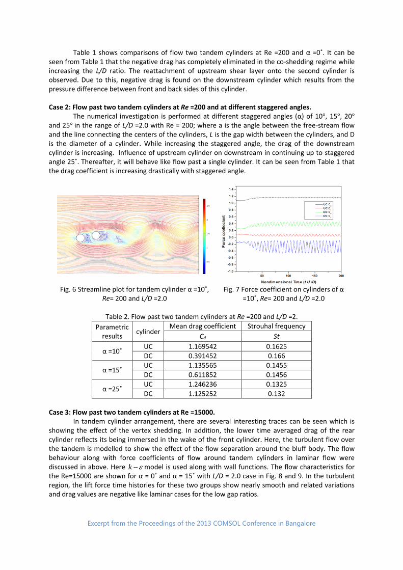
Table 1 shows comparisons of flow two tandem cylinders at Re =200 and α =0˚. It can be seen from Table 1 that the negative drag has completely eliminated in the co-shedding regime while increasing the L/D ratio. The reattachment of upstream shear layer onto the second cylinder is observed. Due to this, negative drag is found on the downstream cylinder which results from the pressure difference between front and back sides of this cylinder. Case 2: Flow past two tandem cylinders at Re =200 and at different staggered angles. The numerical investigation is performed at different staggered angles (α) of 10°, 15°, 20° and 25° in the range of L/D =2.0 with Re = 200; where a is the angle between the free-stream flow and the line connecting the centers of the cylinders, L is the gap width between the cylinders, and D is the diameter of a cylinder. While increasing the staggered angle, the drag of the downstream cylinder is increasing. Influence of upstream cylinder on downstream in continuing up to staggered angle 25˚. Thereafter, it will behave like flow past a single cylinder. It can be seen from Table 1 that the drag coefficient is increasing drastically with staggered angle.
Fig. 6 Streamline plot for tandem cylinder α =10˚,
Re= 200 and L/D =2.0 Fig. 7 Force coefficient on cylinders of α
=10˚, Re= 200 and L/D =2.0
Table 2. Flow past two tandem cylinders at Re =200 and L/D =2.
Parametric results
cylinder Mean drag coefficient Strouhal frequency
Cd St
α =10˚ UC 1.169542 0.1625
DC 0.391452 0.166
α =15˚ UC 1.135565 0.1455
DC 0.611852 0.1456
α =25˚ UC 1.246236 0.1325
DC 1.125252 0.132
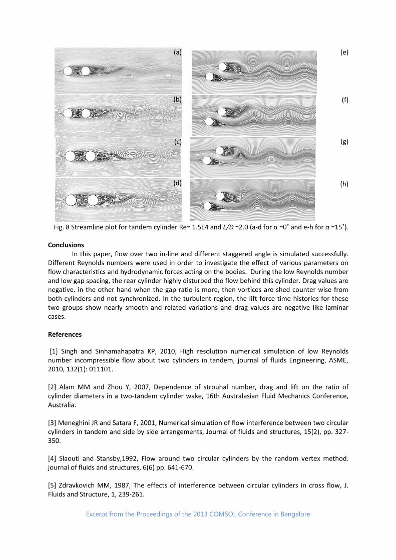
Case 3: Flow past two tandem cylinders at Re =15000. In tandem cylinder arrangement, there are several interesting traces can be seen which is showing the effect of the vertex shedding. In addition, the lower time averaged drag of the rear cylinder reflects its being immersed in the wake of the front cylinder. Here, the turbulent flow over the tandem is modelled to show the effect of the flow separation around the bluff body. The flow behaviour along with force coefficients of flow around tandem cylinders in laminar flow were discussed in above. Here k model is used along with wall functions. The flow characteristics for the Re=15000 are shown for α = 0˚ and α = 15˚ with L/D = 2.0 case in Fig. 8 and 9. In the turbulent region, the lift force time histories for these two groups show nearly smooth and related variations and drag values are negative like laminar cases for the low gap ratios.
Excerpt from the Proceedings of the 2013 COMSOL Conference in Bangalore
(a) (e)
(b) (f)
(c) (g)
(d) (h)
Fig. 8 Streamline plot for tandem cylinder Re= 1.5E4 and L/D =2.0 (a-d for α =0˚ and e-h for α =15˚). Conclusions In this paper, flow over two in-line and different staggered angle is simulated successfully. Different Reynolds numbers were used in order to investigate the effect of various parameters on flow characteristics and hydrodynamic forces acting on the bodies. During the low Reynolds number and low gap spacing, the rear cylinder highly disturbed the flow behind this cylinder. Drag values are negative. in the other hand when the gap ratio is more, then vortices are shed counter wise from both cylinders and not synchronized. In the turbulent region, the lift force time histories for these two groups show nearly smooth and related variations and drag values are negative like laminar cases. References
[1] Singh and Sinhamahapatra KP, 2010, High resolution numerical simulation of low Reynolds number incompressible flow about two cylinders in tandem, journal of fluids Engineering, ASME, 2010, 132(1): 011101. [2] Alam MM and Zhou Y, 2007, Dependence of strouhal number, drag and lift on the ratio of cylinder diameters in a two-tandem cylinder wake, 16th Australasian Fluid Mechanics Conference, Australia. [3] Meneghini JR and Satara F, 2001, Numerical simulation of flow interference between two circular cylinders in tandem and side by side arrangements, Journal of fluids and structures, 15(2), pp. 327-350. [4] Slaouti and Stansby,1992, Flow around two circular cylinders by the random vertex method. journal of fluids and structures, 6(6) pp. 641-670. [5] Zdravkovich MM, 1987, The effects of interference between circular cylinders in cross flow, J. Fluids and Structure, 1, 239-261.