Numerical investigation of flow structure in hydraulic ... · PDF fileNumerical investigation...
4
Numerical investigation of flow structure in hydraulic turbines of high- head power development Dmitry Platonov, Andrey Minakov, Andrey Sentyabov, Dmitry Dekterev Department of Thermal Physics Siberian Federal University Krasnoyarsk, Svobodny pr., 79 Russia Department of Physical Bases of Energy Technologies Institute of Thermophysics, Novosibirsk Acad. Lavrentyev ave., 1 Russia [email protected] http://www.sfu-kras.ru Abstract: - Numerical technique for calculating pressure pulsations in a high-head hydro power plant (HHPP) is presented in the paper. The results of application of the numerical technique for description of unsteady turbulent flow in a flow path of a water turbine are presented. Adaptation of numerical method performed on the results of the simulation of turbulent unsteady flow in the flow path of the high-head hydro power plant is carried out. The structure of the flow behind the runner and its influence on the intensity of non- stationary processes was analyzed. Comparison of calculation results with the prototype experimental data was carried out. A good agreement between theory and experiment was obtained. Key-Words: Francis turbine, numerical simulation, pressure pulsation, the precession of the vortex rope, turbulence, CFD 1 Introduction An important task for HHPP is regulation of power in the energy system. During load changing hydraulic units repeatedly undergo off-design modes of operation. Under these flow conditions a significant part of swirl, after passing through the water turbine runner, is remained. With the instability of swirling flow is related the emergency of intense low-frequency hydrodynamic fluctuations that threaten the reliability of turbine design [1-2]. Vortex rope precession is a serious danger for the hydraulic turbine equipment in relation with the powerful flow pulsations that lead to strong vibrations of hydraulic turbine construction and in the case of resonance can lead to destruction of the equipment. Pressure pulsations generated by the vortex rope precession, may also affect cavitations processes, enhancing cavitations erosion. To predict the resonance phenomena and search methods of suppressing instability requires detailed information about the characteristics of the pulsation modes and flow structure. It should be noted that the developed approaches must meet the requirements of minimizing energy losses (increase efficiency of water turbine), which also can be realized only through in-depth understanding of the hydrodynamic processes occurring in the flow of hydraulic turbine parts. The development of computer technology has made it possible to use modern methods of computational fluid dynamics to the description of turbulent flows in geometrically complex spatial objects, such as hydraulic turbine flow path. Recently there appeared a large number of papers in which three-dimensional formulation in the calculations of various processes in hydraulic turbines were made [3-6]. 2 Mathematical model Describing the flows in the flow path of water turbines one have to face several problems. The first challenge is related to modeling turbulence in channels of complex geometric shapes and strong swirl flow. At the same time for engineering calculations turbulence models, quite accurate describing not only required average fields, but also large-scale flow pulsations. Widely spread in engineering calculations k-ε and k-ω turbulence models poorly describe such flows. To improve the modeling of turbulent swirling flows scientists are trying either to modify existing URANS turbulence models or use techniques which resolve large-scale turbulent eddies (LES, DES) [7,8]. Swirling flow in hydraulic turbines can be accompanied by the precession of the vortex core. D. Platonov et al. International Journal of Theoretical and Applied Mechanics http://www.iaras.org/iaras/journals/ijtam ISSN: 2367-8992 61 Volume 1, 2016
-
Upload
phungnguyet -
Category
Documents
-
view
219 -
download
2
Transcript of Numerical investigation of flow structure in hydraulic ... · PDF fileNumerical investigation...
Numerical investigation of flow structure in hydraulic turbines of high-
head power development
Dmitry Platonov, Andrey Minakov, Andrey Sentyabov, Dmitry Dekterev
Department of Thermal Physics
Siberian Federal University Krasnoyarsk,
Svobodny pr., 79
Russia
Department of Physical Bases of Energy
Technologies
Institute of Thermophysics, Novosibirsk
Acad. Lavrentyev ave., 1
Russia
[email protected] http://www.sfu-kras.ru
Abstract: - Numerical technique for calculating pressure pulsations in a high-head hydro power plant
(HHPP) is presented in the paper. The results of application of the numerical technique for description of
unsteady turbulent flow in a flow path of a water turbine are presented. Adaptation of numerical method
performed on the results of the simulation of turbulent unsteady flow in the flow path of the high-head hydro
power plant is carried out. The structure of the flow behind the runner and its influence on the intensity of non-
stationary processes was analyzed. Comparison of calculation results with the prototype experimental data was
carried out. A good agreement between theory and experiment was obtained.
Key-Words: Francis turbine, numerical simulation, pressure pulsation, the precession of the vortex rope,
turbulence, CFD
1 Introduction An important task for HHPP is regulation of
power in the energy system. During load changing
hydraulic units repeatedly undergo off-design
modes of operation. Under these flow conditions a
significant part of swirl, after passing through the
water turbine runner, is remained. With the
instability of swirling flow is related the emergency
of intense low-frequency hydrodynamic fluctuations
that threaten the reliability of turbine design [1-2].
Vortex rope precession is a serious danger for
the hydraulic turbine equipment in relation with the
powerful flow pulsations that lead to strong
vibrations of hydraulic turbine construction and in
the case of resonance can lead to destruction of the
equipment. Pressure pulsations generated by the
vortex rope precession, may also affect cavitations
processes, enhancing cavitations erosion. To predict
the resonance phenomena and search methods of
suppressing instability requires detailed information
about the characteristics of the pulsation modes and
flow structure. It should be noted that the developed
approaches must meet the requirements of
minimizing energy losses (increase efficiency of
water turbine), which also can be realized only
through in-depth understanding of the
hydrodynamic processes occurring in the flow of
hydraulic turbine parts.
The development of computer technology has
made it possible to use modern methods of
computational fluid dynamics to the description of
turbulent flows in geometrically complex spatial
objects, such as hydraulic turbine flow path.
Recently there appeared a large number of papers in
which three-dimensional formulation in the
calculations of various processes in hydraulic
turbines were made [3-6].
2 Mathematical model Describing the flows in the flow path of water
turbines one have to face several problems. The first
challenge is related to modeling turbulence in
channels of complex geometric shapes and strong
swirl flow. At the same time for engineering
calculations turbulence models, quite accurate
describing not only required average fields, but also
large-scale flow pulsations. Widely spread in
engineering calculations k-ε and k-ω turbulence
models poorly describe such flows. To improve the
modeling of turbulent swirling flows scientists are
trying either to modify existing URANS turbulence
models or use techniques which resolve large-scale
turbulent eddies (LES, DES) [7,8].
Swirling flow in hydraulic turbines can be
accompanied by the precession of the vortex core.
D. Platonov et al.International Journal of Theoretical and Applied Mechanics
http://www.iaras.org/iaras/journals/ijtam
ISSN: 2367-8992 61 Volume 1, 2016
For modeling such phenomenon it is necessary to
use non stationary, in particular, large-eddy
simulation methods such as the method of large-
eddy simulation (Large Eddy Simulation – LES).
However, its use requires a very detailed grid,
especially near the walls. At the same time RANS
models are quite economical and have a good
description of the boundary layers. To combine the
advantages of these approaches in operation the
method of detached eddy simulation (DES) was
proposed. The first DES version was based on the
model of Spalart-Allmaras. Later DES method has
been used with other models of turbulence, there
have been various modifications.
In the simulation of hydraulic turbines it is
necessary to consider the rotation of the runner and
the rotor-stator interaction. There are many
approaches for modeling flows with rotating bodies,
they include: dynamic grid, moving mesh method
based on the transition in a moving coordinate
system. The most common and simple way to model
the runner rotation is to use a rotating coordinate
system. The transition to a rotating coordinate
system allows to simulate flow in an approximation
in which the runner is fixed and swirl flows pass
through it. This formulation is often referred to as
"frozen rotor". In this paper, modeling of the runner
rotation was performed in a form of frozen rotor.
Conducted numerous test calculations show the
correctness of this approach, both in the description
of integral characteristics of flow and pulsation.
Below the basic equations of mathematical
models expressing the conservation, laws in the
rotating coordinate system are presented.
The continuity equation (conservation of
mass):
0
vt
Momentum equation (conservation of
momentum) in a rotating frame of reference for
relative velocities:
0( ) ( ) (2 ( ))
vv v τ τ g Ω v +Ω Ω r
m tpt
where: v - fluid velocity vector, τ - viscous stress
tensor, Ω- angular velocity of runner rotation, p -
static pressure , - density. In the transition to a
rotating coordinate system on the right side of the
equation of conservation of momentum Coriolis’
force and the centrifugal force are written.
Components of the viscous stress tensor is
defined as:
2( )
3
jm i k
ij ij
j i k
uu u
x x x
where: t - dynamic (molecular) viscosity, iu -
components of velocity vector, ji - Kronecker’s
delta.
Two turbulence modeling approach were
used. The first one is second order closure, i.e.
Reynolds stress model (RSM) and the second one is
detached eddy simulation (DES) [5,6].
Earlier test calculations have shown that this
technique is acceptable for calculation period of
time can reliably consider large-scale turbulent
fluctuations throughout the flow path of the water
turbine and estimate their frequency response
characteristics.
A few words about the numerical approach.
Discretization of transport equation was carried out
by the control volume method on unstructured grids.
Relation of velocity and pressure fields for
incompressible fluid was realized using the
procedure implemented by SIMPLE-C. For the
approximation of the convective terms in the
equation for momentum components scheme Quick
(Leonardo scheme) was used. For the approximation
of convective terms in the equations for turbulent
characteristics up-wind scheme of the second order
was used. Unsteady terms are approximated by the
implicit scheme of the 2nd accuracy order. The
diffusion terms are approximated by the scheme of
the 2nd order.
3 Francis turbine The section presents the results of simulation
of the flow in turbine Francis-99. Three operation
point proposed for the Francis-99 workshop are
calculated. Geometry data provided by the
workshop committee were used [9]. Computational
domain includes the runner and the draft tube. The
mesh consists of 6 mln. control volumes. Constant
radial and tangential velocity components were set
at the runner inlet. Angle between velocity direction
and the runner inlet corresponds to guide vane
angle. Outflow boundary conditions were set at the
draft tube outlet.
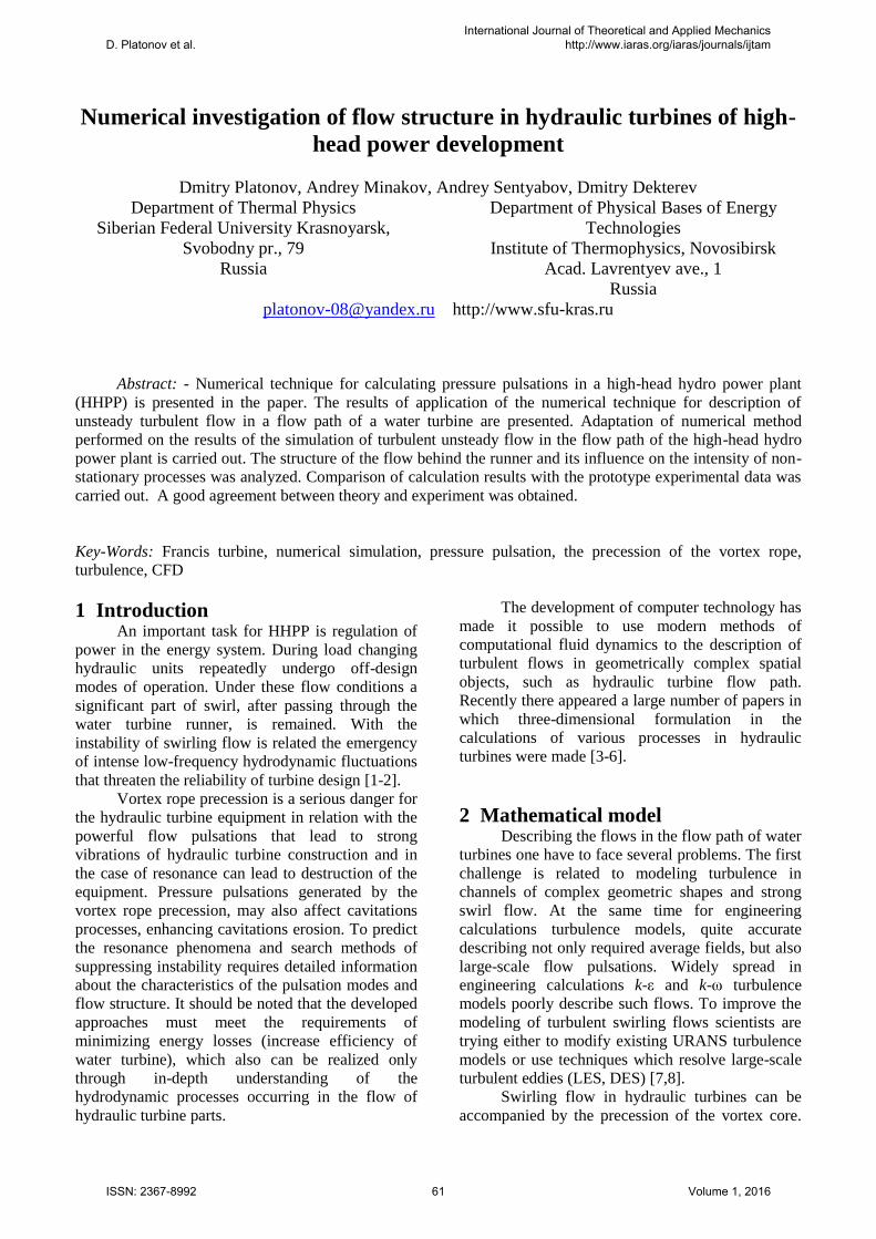
Three operation points were calculated with
of Reynolds stress model. Part load and high load
operation points were also calculated with DES
method [10]. Fig. 1 shows velocity magnitude in
central cross-section for three operation points.
Flow of HL and BEP modes are similar. Narrow
concentrated vortex is formed under the runner tip.
On the other hand, at PL operation point axial flow
is close to the draft tube wall. At this operation point
D. Platonov et al.International Journal of Theoretical and Applied Mechanics
http://www.iaras.org/iaras/journals/ijtam
ISSN: 2367-8992 62 Volume 1, 2016
wide recirculation zone is formed at the axis in the
draft tube cone.
Fig. 1 Velocity magnitude in central plane; a) part
load, b) best efficiency point, c) high load
a
b
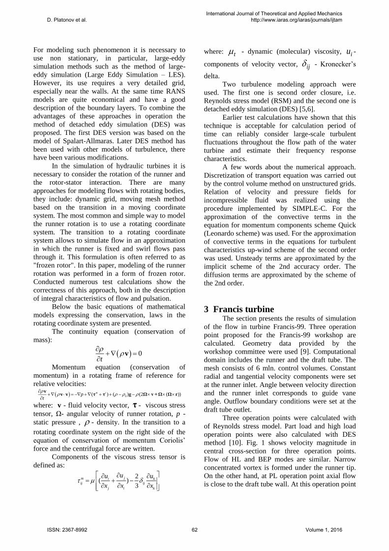
Fig. 2 Axial and swirl velocity components in
the draft tube, part load; a) top line, b) bottom
line
4 Aerodynamic stand
The section presents the results of simulation
of the flow in the aerodynamic turbine.
The aerodynamic contour of the stand
contains all the basic functionality of the hydro
turbine units: spiral case, guide vane, runner and
draft tube.
For the rotation of the impeller used a
computer-controlled actuator that allows
measurements on different modes of hydro turbines.
To create and regulate the incoming pressure of a
centrifugal pump.
The calculations used unstructured grids of
varying detail.
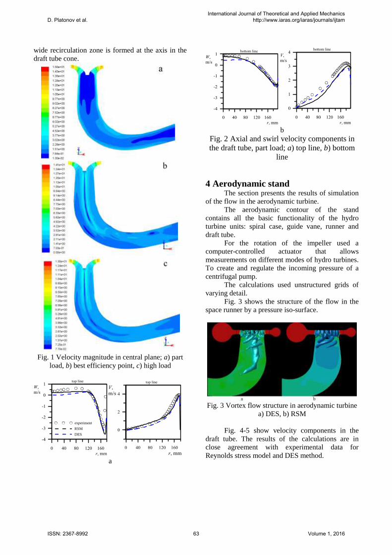
Fig. 3 shows the structure of the flow in the
space runner by a pressure iso-surface.
Fig. 3 Vortex flow structure in aerodynamic turbine
a) DES, b) RSM
Fig. 4-5 show velocity components in the
draft tube. The results of the calculations are in
close agreement with experimental data for
Reynolds stress model and DES method.
D. Platonov et al.International Journal of Theoretical and Applied Mechanics
http://www.iaras.org/iaras/journals/ijtam
ISSN: 2367-8992 63 Volume 1, 2016
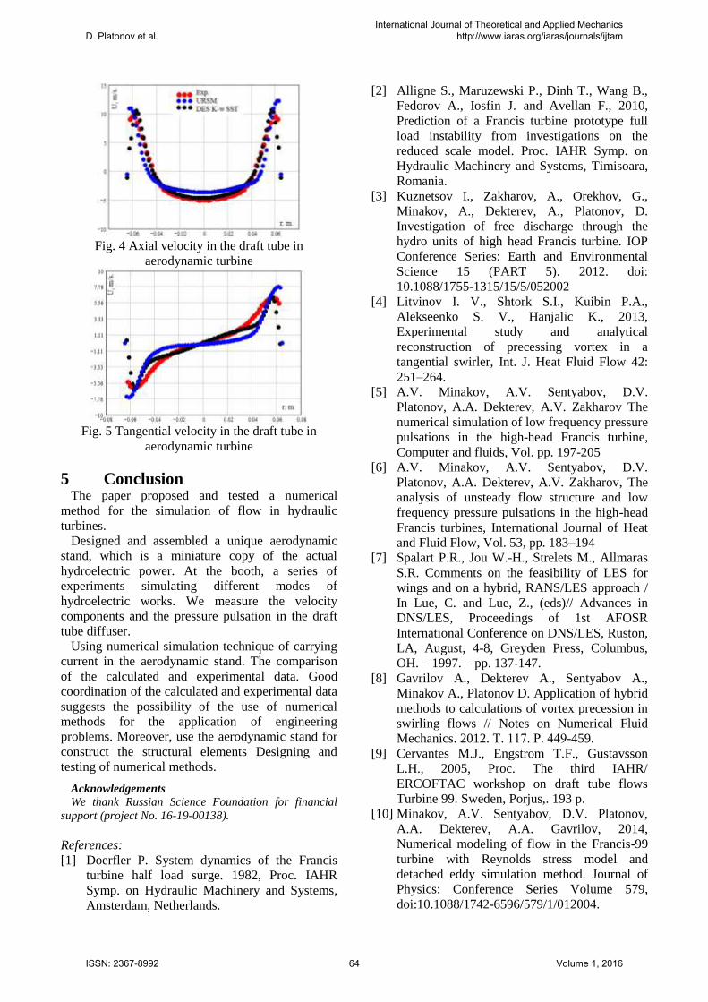
Fig. 4 Axial velocity in the draft tube in
aerodynamic turbine
Fig. 5 Tangential velocity in the draft tube in
aerodynamic turbine
5 Conclusion The paper proposed and tested a numerical
method for the simulation of flow in hydraulic
turbines.
Designed and assembled a unique aerodynamic
stand, which is a miniature copy of the actual
hydroelectric power. At the booth, a series of
experiments simulating different modes of
hydroelectric works. We measure the velocity
components and the pressure pulsation in the draft
tube diffuser.
Using numerical simulation technique of carrying
current in the aerodynamic stand. The comparison
of the calculated and experimental data. Good
coordination of the calculated and experimental data
suggests the possibility of the use of numerical
methods for the application of engineering
problems. Moreover, use the aerodynamic stand for
construct the structural elements Designing and
testing of numerical methods.
Acknowledgements
We thank Russian Science Foundation for financial
support (project No. 16-19-00138).
References:
[1] Doerfler P. System dynamics of the Francis
turbine half load surge. 1982, Proc. IAHR
Symp. on Hydraulic Machinery and Systems,
Amsterdam, Netherlands.
[2] Alligne S., Maruzewski P., Dinh T., Wang B.,
Fedorov A., Iosfin J. and Avellan F., 2010,
Prediction of a Francis turbine prototype full
load instability from investigations on the
reduced scale model. Proc. IAHR Symp. on
Hydraulic Machinery and Systems, Timisoara,
Romania.
[3] Kuznetsov I., Zakharov, A., Orekhov, G.,
Minakov, A., Dekterev, A., Platonov, D.
Investigation of free discharge through the
hydro units of high head Francis turbine. IOP
Conference Series: Earth and Environmental
Science 15 (PART 5). 2012. doi:
10.1088/1755-1315/15/5/052002
[4] Litvinov I. V., Shtork S.I., Kuibin P.A.,
Alekseenko S. V., Hanjalic K., 2013,
Experimental study and analytical
reconstruction of precessing vortex in a
tangential swirler, Int. J. Heat Fluid Flow 42:
251–264.
[5] A.V. Minakov, A.V. Sentyabov, D.V.
Platonov, A.A. Dekterev, A.V. Zakharov The
numerical simulation of low frequency pressure
pulsations in the high-head Francis turbine,
Computer and fluids, Vol. pp. 197-205
[6] A.V. Minakov, A.V. Sentyabov, D.V.
Platonov, A.A. Dekterev, A.V. Zakharov, The
analysis of unsteady flow structure and low
frequency pressure pulsations in the high-head
Francis turbines, International Journal of Heat
and Fluid Flow, Vol. 53, pp. 183–194
[7] Spalart P.R., Jou W.-H., Strelets M., Allmaras
S.R. Comments on the feasibility of LES for
wings and on a hybrid, RANS/LES approach /
In Lue, C. and Lue, Z., (eds)// Advances in
DNS/LES, Proceedings of 1st AFOSR
International Conference on DNS/LES, Ruston,
LA, August, 4-8, Greyden Press, Columbus,
OH. – 1997. – pp. 137-147.
[8] Gavrilov A., Dekterev A., Sentyabov A.,
Minakov A., Platonov D. Application of hybrid
methods to calculations of vortex precession in
swirling flows // Notes on Numerical Fluid
Mechanics. 2012. Т. 117. P. 449-459.
[9] Cervantes M.J., Engstrom T.F., Gustavsson
L.H., 2005, Proc. The third IAHR/
ERCOFTAC workshop on draft tube flows
Turbine 99. Sweden, Porjus,. 193 p.
[10] Minakov, A.V. Sentyabov, D.V. Platonov,
A.A. Dekterev, A.A. Gavrilov, 2014,
Numerical modeling of flow in the Francis-99
turbine with Reynolds stress model and
detached eddy simulation method. Journal of
Physics: Conference Series Volume 579,
doi:10.1088/1742-6596/579/1/012004.
D. Platonov et al.International Journal of Theoretical and Applied Mechanics
http://www.iaras.org/iaras/journals/ijtam
ISSN: 2367-8992 64 Volume 1, 2016