Numerical investigation of dynamic embedment of offshore ... · Numerical investigation of dynamic...
4
2347 Numerical investigation of dynamic embedment of offshore pipelines Étude numérique de l’ancrage dynamique de conduites enterrées maritimes Dutta S., Hawlader B. Memorial University, St. John’s, Canada. Phillips R. C-CORE, St. John’s, Canada. ABSTRACT: Pipelines are one of the key components of offshore oil and gas development programs. Deep water pipelines are often laid on the seabed and penetrate into soil a fraction of their diameter. High operating temperature and pressure generate axial stress that could buckle the pipeline laterally. The embedment and formation of soil berm have a significant effect on lateral resistance. The embedment of a pipeline depends on stress concentration at the touchdown point (TDP) and dynamic laying effects. In this study, large deformation finite element modelling of dynamic penetration of offshore pipeline is presented. The Coupled Eulerain Lagrangian (CEL) technique is used to develop finite element model. The pipe is first penetrated into the seabed followed by a small amplitude cyclic lateral motion. Results from the finite element models are compared with centrifuge test results. High plastic shear strain is obtained around the pipeline during cyclic loading which causes significant pipe embedment. The shape of soil berm is different from that of monotonic pipe penetration. RÉSUMÉ : Les conduites enterrées sont un des éléments clés des programmes de développement de pétrole et de gaz. Des conduites enterrées en eau profonde sont souvent mises sur le plancher océanique et pénètrent dans le sol sur une fraction de leur diamètre. La température et la pression de fonctionnement élevées génèrent une contrainte axiale qui peuvent déformer la conduite latéralement. L'ancrage et le sol encaissant ont un effet significatif sur la résistance latérale. L'enfouissement d'une conduite dépend des concentrations de contraintes et des effets dynamiques de la pose. Dans cette étude, une modélisation par éléments finis en grande déformation de la pénétration dynamique de la conduite est présentée. Une technique de type Eulérien Lagrangien (CEL) est utilisée pour développer le modèle éléments finis. Le tuyau est d'abord mis en place dans le fond marin puis subit un mouvement cyclique de faible amplitude latérale. Les résultats des modèles éléments finis sont comparés avec les résultats d’essais en centrifugeuses. D’importantes valeurs de la déformation plastique sont obtenues autour de la canalisation lors du chargement cyclique ce qui nécessite un ancrage suffisant de la conduite. La forme du sol encaissant est différente de celle du tuyau mis en place statiquement. KEYWORDS: pipelines, dynamic embedment, clay, large deformation analysis. 1 INTRODUCTION As-laid pipelines are commonly used in deepwater. During installation the as-laid pipeline could be penetrated a fraction of its diameter into the seabed (Bruton et al. 2006), and a soil berm could be formed. The soil around the pipelines provides not only the thermal insulation and hydrodynamic stability to the pipe but also resistance to pipeline walking and lateral buckling during high operating temperature and pressure. Accurate assessment of as-laid pipe embedment is extremely difficult. Depending upon sea state, vessel conditions, pipe stiffness and soil conditions, the pipeline might experience both in-plane and out-of-plane cyclic motion during installation (Westgate et al. 2010, 2012), which causes dynamic embedment of the pipeline. The penetration of a pipeline under static load can be obtained using bearing capacity theory, analytical solution or finite element techniques. In the current engineering practice, two additional factors are used to estimate the embedment of pipelines: (a) additional vertical force near the TDP (the point where the pipe first touches the soil) due to catenary effects and (b) dynamic lay effects. A number of methods have been proposed in the past to estimate these factors (Carneiro et al. 2010, Oliphant and Yun 2011). For example, Randolph and White (2008) proposed an empirical equation to calculate the touchdown lay factor (f lay ) using pipe submerged weight, bending rigidity, horizontal component of effective tension, lay angle, water depth and seabed stiffness. The embedment factor for dynamic lay effects (f dyn ) varies between 2 and 10 (Lund 2000, Bruton et al. 2006). This wide range of variation in this factor makes the assessment of pipe embedment very difficult. During installation, both vertical and lateral pipe motions can soften the seabed soil near the pipe. Soil softening/remolding together with water entrainment can reduce the undrained shear strength of soil. Field observation (Westgate et al. 2010) and physical modeling using geotechnical centrifuge (Cheuk and White 2011) show that the horizontal cyclic motion, although small amplitude, has a significant effect on pipe embedment. The main purpose of this study is to conduct large deformation finite element (FE) analysis for dynamic events during the installation of pipeline. Coupled Eulerian Lagrangian (CEL) technique is adopted in the analysis using ABAQUS FE software. Four FE models are developed for two different soils: kaolin and high plasticity clays (plasticity index for kaolin is 34 and for high plastic clay is 100-130, Cheuk and White 2011). The results are compared with the centrifuge test results vailable in the literature. a 2 PROBLEM DEFINITION. The problem considered in the present finite element (FE) modelling is shown in Fig.1. During laying, offshore pipelines usually penetrate vertically into the seabed due to its self-weight and catenary effect near the touchdown zone (TDZ). The vessel movement from wave loading could cause small amplitude cyclic motions in the x-direction. As the pipeline is under a vertical load (p 0 ), the lateral movement in the x-direction could cause additional vertical penetration as shown by Stage-II and III in Fig. 1.
Transcript of Numerical investigation of dynamic embedment of offshore ... · Numerical investigation of dynamic...
2347
Numerical investigation of dynamic embedment of offshore pipelines
Étude numérique de l’ancrage dynamique de conduites enterrées maritimes
Dutta S., Hawlader B. Memorial University, St. John’s, Canada.Phillips R. C-CORE, St. John’s, Canada.
ABSTRACT: Pipelines are one of the key components of offshore oil and gas development programs. Deep water pipelines are oftenlaid on the seabed and penetrate into soil a fraction of their diameter. High operating temperature and pressure generate axial stressthat could buckle the pipeline laterally. The embedment and formation of soil berm have a significant effect on lateral resistance. Theembedment of a pipeline depends on stress concentration at the touchdown point (TDP) and dynamic laying effects. In this study, large deformation finite element modelling of dynamic penetration of offshore pipeline is presented. The Coupled EulerainLagrangian (CEL) technique is used to develop finite element model. The pipe is first penetrated into the seabed followed by a small amplitude cyclic lateral motion. Results from the finite element models are compared with centrifuge test results. High plastic shearstrain is obtained around the pipeline during cyclic loading which causes significant pipe embedment. The shape of soil berm is different from that of monotonic pipe penetration.
RÉSUMÉ : Les conduites enterrées sont un des éléments clés des programmes de développement de pétrole et de gaz. Des conduites enterrées en eau profonde sont souvent mises sur le plancher océanique et pénètrent dans le sol sur une fraction de leur diamètre. La température et la pression de fonctionnement élevées génèrent une contrainte axiale qui peuvent déformer la conduite latéralement.L'ancrage et le sol encaissant ont un effet significatif sur la résistance latérale. L'enfouissement d'une conduite dépend des concentrations de contraintes et des effets dynamiques de la pose. Dans cette étude, une modélisation par éléments finis en grande déformation de la pénétration dynamique de la conduite est présentée. Une technique de type Eulérien Lagrangien (CEL) est utilisée pour développer le modèle éléments finis. Le tuyau est d'abord mis en place dans le fond marin puis subit un mouvement cyclique de faible amplitude latérale. Les résultats des modèles éléments finis sont comparés avec les résultats d’essais en centrifugeuses.D’importantes valeurs de la déformation plastique sont obtenues autour de la canalisation lors du chargement cyclique ce quinécessite un ancrage suffisant de la conduite. La forme du sol encaissant est différente de celle du tuyau mis en place statiquement.
KEYWORDS: pipelines, dynamic embedment, clay, large deformation analysis.
1 INTRODUCTION
As-laid pipelines are commonly used in deepwater. During installation the as-laid pipeline could be penetrated a fraction of its diameter into the seabed (Bruton et al. 2006), and a soil berm could be formed. The soil around the pipelines provides not only the thermal insulation and hydrodynamic stability to the pipe but also resistance to pipeline walking and lateral buckling during high operating temperature and pressure. Accurate assessment of as-laid pipe embedment is extremely difficult. Depending upon sea state, vessel conditions, pipe stiffness and soil conditions, the pipeline might experience both in-plane and out-of-plane cyclic motion during installation (Westgate et al. 2010, 2012), which causes dynamic embedment of the pipeline.
The penetration of a pipeline under static load can be obtained using bearing capacity theory, analytical solution or finite element techniques. In the current engineering practice, two additional factors are used to estimate the embedment of pipelines: (a) additional vertical force near the TDP (the point where the pipe first touches the soil) due to catenary effects and (b) dynamic lay effects. A number of methods have been proposed in the past to estimate these factors (Carneiro et al. 2010, Oliphant and Yun 2011). For example, Randolph and White (2008) proposed an empirical equation to calculate the touchdown lay factor (flay) using pipe submerged weight, bending rigidity, horizontal component of effective tension, lay angle, water depth and seabed stiffness. The embedment factor for dynamic lay effects (fdyn) varies between 2 and 10 (Lund 2000, Bruton et al. 2006). This wide range of variation in this factor makes the assessment of pipe embedment very difficult.
During installation, both vertical and lateral pipe motions can soften the seabed soil near the pipe. Soil softening/remolding together with water entrainment can reduce the undrained shear strength of soil. Field observation (Westgate et al. 2010) and physical modeling using geotechnical centrifuge (Cheuk and White 2011) show that the horizontal cyclic motion, although small amplitude, has a significant effect on pipe embedment.
The main purpose of this study is to conduct large deformation finite element (FE) analysis for dynamic events during the installation of pipeline. Coupled Eulerian Lagrangian (CEL) technique is adopted in the analysis using ABAQUS FE software. Four FE models are developed for two different soils: kaolin and high plasticity clays (plasticity index for kaolin is 34 and for high plastic clay is 100-130, Cheuk and White 2011). The results are compared with the centrifuge test results vailable in the literature. a
2 PROBLEM DEFINITION.
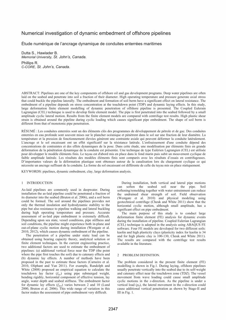
The problem considered in the present finite element (FE) modelling is shown in Fig.1. During laying, offshore pipelines usually penetrate vertically into the seabed due to its self-weight and catenary effect near the touchdown zone (TDZ). The vessel movement from wave loading could cause small amplitude cyclic motions in the x-direction. As the pipeline is under a vertical load (p0), the lateral movement in the x-direction could cause additional vertical penetration as shown by Stage-II and III in Fig. 1.
2348
Proceedings of the 18th International Conference on Soil Mechanics and Geotechnical Engineering, Paris 2013
Figure 1. Problem statement.
3 FINITE ELEMENT MODELLING.
ABAQUS 6.10 EF-1 is used in the present finite element analysis. As the embedment of pipe in the seabed is large deformation problem, the conventional finite element techniques in Lagrangian approach cannot simulate the complete process realistically as numerical difficulties are generally encountered for such large displacements. Therefore, in this study the Coupled Eulerian Lagrangian (CEL) technique currently available in ABAQUS FE software is used. In CEL, the soil flows through the fixed mesh without having any numerical issues. The FE modeling using CEL for pipe embedment into the seabed is presented by the authors previously (Dutta et al. 2012 a&b). A soil domain of 8m×3m ×0.04m (length × height × thickness) is used in this study. The soil is modelled as Eulerain elements and the pipe is modelled as Lagrangian elements. The 1.5 m void space above the soil is required to accommodate the displaced soil mass (Eulerian materials) during pipe displacement. Zero velocity boundary conditions are applied at all faces of the Eulerian domain to make sure that Eulerain materials are within the domain and cannot move outside. However, at the seabed-void interface, no boundary condition is provided so that the soil can flow to the void. That means, the bottom of the model is restrained from any vertical movement, while all the vertical faces are restrained from any lateral movement. The pipe is modeled as a rigid body. During penetration, especially in cyclic loading, the remolding of soil near the pipe could cause significant reduction in undrained shear strength. Smooth pipe/soil interface condition is used for the present analysis. Mesh sensitivity analysis is also performed and an optimum mesh size of 0.04m×0.04m is used (Dutta et al. 2012 a).
The loading is performed in three different stages. First, the geostatic conditions are applied to bring the seabed to in-situ condition. Second, the pipe is penetrated applying a vertical load (p) which is the combined effect of submerged unit weight of the pipe and laying effects. In the third step, 40 cycles of small amplitude (0.05D) lateral displacement are applied using displacement boundary conditions under the constant vertical load p0. Plastic shear strain develops near the pipe during penetration. In the present FE analyses the degradation of undrained shear strength as a function of plastic shear strain is adopted using the following model (Einav and Randolph 2005 Wang et al. 2009 and Zhou and Randolph 2009).
su=[rem+(1-rem)exp(-3/95)]su0 (1)
where trem S1 , St is the soil sensitivity, is the
accumulated equivalent plastic shear strain, su0 is the intact undrained shear strength of soil and ξ95 is the accumulated plastic shear strain at 95% undrained shear strength degradation. The variation of su0 with depth is shown in Fig. 1 and the von-Mises yield criteria is adopted.
In this study four cases are simulated and the results are compared with centrifuge test results of Cheuk and White (2008). Two tests (KC-04 & KC-05) are in kaolin clay and two
(HP-06 & HP-07) are in high plasticity clay. Table 1 shows the parameters used in the FE analyses. The vertical load p for initial static penetration and during cyclic motion are also shown in Table 2. T able 1. Parameters for finite element modelling.
PipePipe diameter, D (mm) Lateral displacement during cyclic motion
800
± 0.05D
Soil Properties KaolinClay
HighPlasticity
Clay Undrained modulus of elasticity, Eu 500su 500su Poisson’s ratio, u 0.495 0.495Undrained shear strength at mudline, sum (kPa) 0.75 0.40 Gradient of shear strength increase, k (kPa/m) 1.6 2.5 Submerged unit weight of soil, (kN/m3) Remoulded soil sensitivity, St
Accumulate absolute plastic shear strain for 95% degradation of soil strength, 95
6.0 4.0 10
3.0 1.7 10
Table 2. Centrifuge test conditions (Cheuk and White 2011). KC-04 KC-05 HP-06 HP-07Pipe vertical load, p (kN/m) 1.17 2.23 1.47 2.61 Initial static embedment, win/D 0.08 0.12 0.10 0.22 Pipe vertical load at cyclic motion, p0 (kN/m)
1.13 2.17 1.43 2.52
4 RESULTS.
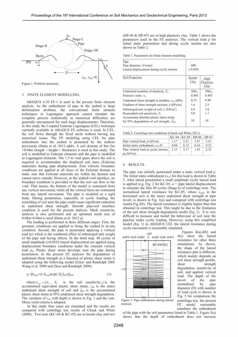
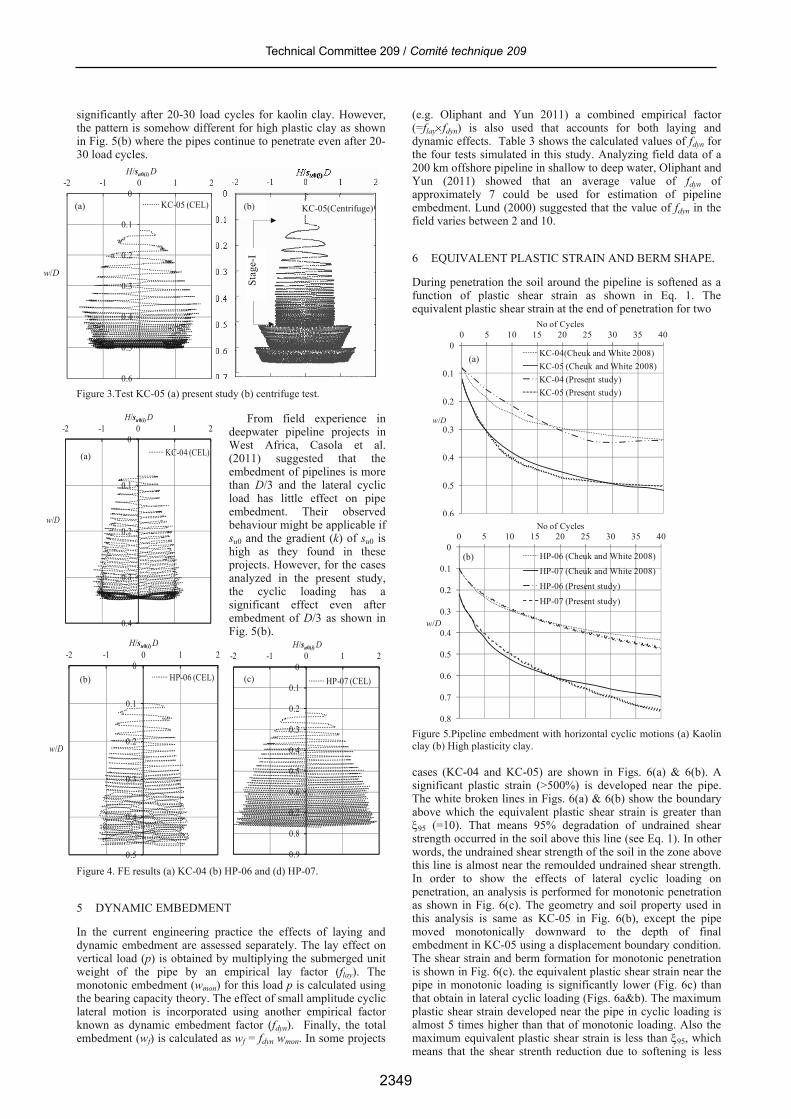
The pipe was initially penetrated under a static vertical load p. The initial static embedment (win) for this load is shown in Table 2. After initial penetration a small amplitude cyclic lateral load is applied (e.g. Fig. 2 for KC-05, u = pipe lateral displacement) to simulate the first 40 cycles (Stage-I) of centrifuge tests. The normalized lateral resistance for KC-05, where su0(i) in the horizontal axis is the intact undrained shear strength at pipe invert, is shown in Fig. 3(a) and comapred with centrifuge test results Fig.3(b). The lateral resistance is slightly higher than that obtained in centrifuge test. This might be due to the limitation of the soil shear strength degradation model (Eq. 1). It is very difficult to measure and model the behaviour of soil near the pipeline under cyclic loading. However, using this simplified model (Eq. 1) in ABAQUS CEL the lateral resistance during cyclic movement is reasonably simulated.
Figures 4(a),4(b) and 4(c) show the lateral resistance for other three simulations. As shown, the shape of the lateral resistance plot is different, which mainly depends on soil shear strength profile, shear strength degradation, sensitivity of soil, and applied vertical load. The depth of the invert of the pipe normalized by pipe diameter (D) with number of load cycle is shown in Fig. 5 for comparison the centrifuge test. the present FE model reasonably simulates the embedment
of the pipe with the soil parameters listed in Table 1. Figure 5(a) shows that the depth of embedment does not increase
x
Z
x
z
D
p0
P
B
ipe
su0 = sum+kz
w
erm
SS
Stage-I
tage-II tage:-III
s
k
um
w/D
Figure 2. Pipe embedment during lateral motions
2349
Technical Committee 209 / Comité technique 209
significantly after 20-30 load cycles for kaolin clay. However, the pattern is somehow different for high plastic clay as shown in Fig. 5(b) where the pipes continue to penetrate even after 20-30 load cycles.
0
0.1
0.2
0.3
0.4
0.5
0.6
-2 -1 0 1 2H/su0(i) D
KC-05 (CEL)
0
0.1
0.2
0.3
0.4
-2 -1 0 1 2
w/D
H/su0(i) D
KC-04 (CEL)
0
0.1
0.2
0.3
0.4
0.5
-2 -1 0 1 2
w/D
H/su0(i) D
HP-06 (CEL)
Figure 3.Test KC-05 (a) present study (b) centrifuge test.
From field experience in deepwater pipeline projects in West Africa, Casola et al. (2011) suggested that the embedment of pipelines is more than D/3 and the lateral cyclic load has little effect on pipe embedment. Their observed behaviour might be applicable if su0 and the gradient (k) of su0 is high as they found in these projects. However, for the cases analyzed in the present study, the cyclic loading has a significant effect even after embedment of D/3 as shown in Fig. 5(b).
Figure 4. FE results (a) KC-04 (b) HP-06 and (d) HP-07.
5 DYNAMIC EMBEDMENT
In the current engineering practice the effects of laying and dynamic embedment are assessed separately. The lay effect on vertical load (p) is obtained by multiplying the submerged unit weight of the pipe by an empirical lay factor (flay). The monotonic embedment (wmon) for this load p is calculated using the bearing capacity theory. The effect of small amplitude cyclic lateral motion is incorporated using another empirical factor known as dynamic embedment factor (fdyn). Finally, the total embedment (wf) is calculated as wf = fdyn wmon. In some projects
(e.g. Oliphant and Yun 2011) a combined empirical factor (=flayfdyn) is also used that accounts for both laying and dynamic effects. Table 3 shows the calculated values of fdyn for the four tests simulated in this study. Analyzing field data of a 200 km offshore pipeline in shallow to deep water, Oliphant and Yun (2011) showed that an average value of fdyn of approximately 7 could be used for estimation of pipeline embedment. Lund (2000) suggested that the value of fdyn in the field varies between 2 and 10.
q for two
with horizontal cyclic motions (a) Kaolin (b) High plasticity clay.
(a) (b) KC-05(Centrifuge)
Stag
e-I 6 EQUIVALENT PLASTIC STRAIN AND BERM SHAPE.
During penetration the soil around the pipeline is softened as a function of plastic shear strain as shown in Eq. 1. The
w/D
e uivalent plastic shear strain at the end of penetration
0
0.1
0.2
0.3
0.4
0.5
0 5 10 15 20 25 30 35 40
w/D
No of Cycles
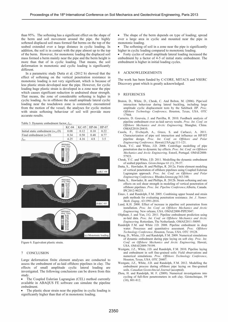
Figure 5.Pipeline embedment clay cases (KC-04 and KC-05) are shown in Figs. 6(a) & 6(b). A significant plastic strain (>500%) is developed near the pipe. The white broken lines in Figs. 6(a) & 6(b) show the boundary above which the equivalent plastic shear strain is greater than 95 (=10). That means 95% degradation of undrained shear strength occurred in the soil above this line (see Eq. 1). In other words, the undrained shear strength of the soil in the zone above this line is almost near the remoulded undrained shear strength. In order to show the effects of lateral cyclic loading on penetration, an analysis is performed for monotonic penetration as shown in Fig. 6(c). The geometry and soil property used in this analysis is same as KC-05 in Fig. 6(b), except the pipe moved monotonically downward to the depth of final embedment in KC-05 using a displacement boundary condition. The shear strain and berm formation for monotonic penetration is shown in Fig. 6(c). the equivalent plastic shear strain near the pipe in monotonic loading is significantly lower (Fig. 6c) than that obtain in lateral cyclic loading (Figs. 6a&b). The maximum plastic shear strain developed near the pipe in cyclic loading is almost 5 times higher than that of monotonic loading. Also the maximum equivalent plastic shear strain is less than 95, which means that the shear strenth reduction due to softening is less
0
0.1
0.2
0.3
0.4
0.5
0.6
0.7
0.8
0.9
-2 -1 0 1 2H/su0(i) D
HP-07 (CEL)(c) (b)
0.6
KC-04(Cheuk and White 2008)(a) KC-05 (Cheuk and White 2008)KC-04 (Present study)KC-05 (Present study)
(a)
0
0.1
0.2
0.3
0.4
0.5
0.6
0.7
0 5 10 15 20 25 30 35 40
w/D
No of Cycles
0.8
HP-06 (Cheuk and White 2008)(b) HP-07 (Cheuk and White 2008)
HP-06 (Present study)
HP-07 (Present study)
2350
Proceedings of the 18th International Conference on Soil Mechanics and Geotechnical Engineering, Paris 2013
than 95%. The softening has a significant effect on the shape of the berm and soil movement around the pipe. the highly softened displaced soil mass formed flat berms on the top of the seabed extended over a large distance in cyclic loading. In addition, the soil is in contact with the pipe almost up to the top of the berm. However, for monotonic loading the displaced soil mass formed a berm mainly near the pipe and the berm height is more than that of in cyclic loading. That means, the soil deformation in monotonic and cyclic loading is significantly dif
ning behaviour of soil will provide more accurate results.
able 3. Dynamic embedment factoK K H
ferent. In a parametric study Dutta et al. (2012 b) showed that the
effect of softening on the vertical penetration resistance in monotonic loading is not very significant, which is because of less plastic strain developed near the pipe. However, for cyclic loading huge plastic strain is developed in a zone near the pipe which causes significant reduction in undrained shear strength. That means, the zone of considerable softening is higher in cyclic loading. As in offshore the small amplitude lateral cyclic loading near the touchdown zone is commonly encountered from the motion of the vessel, the analyses for cyclic motion with strain softe
T r, fdyn. C-04 C-05 HP-06 P-07Initial static embedment (win/D) 0.08 0.12 0.10 0.22 Final embedment (w/D) 0.34 0.50 0.48 0.77 fdyn 4.25 4.16 4.8 3.5 Figure 6. Equivalent plastic strain.
ated. The following conclusions can be drawn from this
BAQUS FE software can simulate the pipeline
oading is
ipe in
c loading. Forty cycles of small amplitude lateral loading increased the
initial static embedment. The cycles.
The work has been funded by C-CORE, MITACS and NSERC h is greatly acknowledged.
9
Bru
Che
Geotechncial Journal (accepted). Zhou, H. and Randolph, M. F. (2009). Numerical investigations into
cycling of full-flow penetrometers in soft clay. Géotechnique, 59 (10), 801-812.
The shape of the berm depends on type of loading; spread over a large area in cyclic and mounted near the pmonotonic loading. The softening of soil in a zone near the pipe is significantly higher in cyclic loading compared to monotoni
embedment by a factor of 4-5 ofembedment is higher in initial loading
8 ACKNOWLEDGEMENTS
Discovery grant whic
REFERENCES
ton, D., White, D., Cheuk, C. And Bolton, M. (2006). Pipe/soil interaction behaviour during lateral buckling, including large amplitude cyclic displacement tests by the Safebuck JIP. Proc. Offshore Technology Conference, Houston, Texas, USA. OTC 17944.
neiro, D. Gouveia, J. and ParCar rilha, R. 2010. Feedback analysis of pipeline embedment over as-laid survey results. Proc. Int. Conf. on Offshore Mechanics and Arctic Engineering, Shanghai, China. OMAE2010-20410.
ola, F., El-chayeb, A., Greco, S. and CarlucCas ci, A. 2011. Characterization of pipe soil interaction and influence on HP/HT pipeline design. Proc. Int. Conf. on Offshore and Polar Engineering Conference, Hawaii,USA,pg:111-121.
Cheuk, Y.C. and White, J.D. 2008. Centrifuge modelling of pipe penetration due to dynamic lay effects. Proc. Int. Conf. on Offshore Mechanics and Arctic Engineering, Estoril, Portugal. OMAE2008-57923. uk, Y.C. and White, J.D. 2011. Modelling the dynamic embedment of seabed pipelines. Géotechnique 61 (1), 39-57.
ta, S., Hawlader, B. and Phillips, R. 2012a. Finite elemDut ent modeling of vertical penetration of offshore pipelines using Coupled Eulerian Lagrangian approach. Proc. Int. Conf. on Offshore and Polar Engineering Conference, Rhodes,Greece,pg:343-348.
ta, S., Hawlader, B
(a)KC-04
Dut . and Phillips, R. 2012b. Strain softening and rate effects on soil shear strength in modeling of vertical penetration of offshore pipelines. Proc. Int. Pipeline Conference,Alberta, Canada. IPC2012-90233.
Einav, I. and Randolph, F.M. 2005. Combining upper bound and strain path methods for evaluating penetration resistance. Int. J. Numer. Meth. Engng., 63:1991-2016.
(b)KC-05 Lund, K.H. 2000. Effect of increase in pipeline soil penetration from installation. Proc. Int. Conf. on Offshore Mechanics and Arctic Engineering, New orleans, USA. OMAE2000-PIPE5047.
Oliphant, J. and Yun, J.G. 2011. Pipeline embedment prediction using as-laid data. Proc. Int. Conf. on Offshore Mechanics and Arctic Engineering, Rotterdam, The Netherlands. OMAE2011-50095.
Randolph F.M. and White J.D. 2008. Pipeline embedment in deep water: Processes and quantitative assesment. Proc. Offshore Technology Conference, Houston, Texas, USA. OTC 19128.
ng, D., White, J.D. and Rand
7 CONCLUSION
Large deformation finite element analyses are conducted to assess the embedment of as-laid offshore pipelines in clay. The effects of small amplitude cyclic lateral loading are investig
Wa olph, F.M. 2009. Numerical simulations of dynamic embedment during pipe laying on soft clay. Proc. Int. Conf. on Offshore Mechanics and Arctic Engineering, Hawaii, USA. OMAE2009-79199.
stgate, J.Z., White, J.D. and Randolp
(c) Monotonic loading
We h, F.M. 2010. Pipeline laying and embedment in soft fine-grained soils: Field observations and numerical simulations. Proc. Offshore Technology Conference, Houston, Texas, USA. OTC 20407.
Westgate, J.Z., White, J.D. and Randolph, F.M. 2012. Modelling the embedment process during offshore pipe laying on fine-grained soils. Canadian
study. The Coupled Eulerian Lagrangian (CEL) method currently available in Aembedment. The plastic shear strain near the pipeline in cyclic lsignificantly higher than that of in monotonic loading.