A NUMERICAL ANALYSIS OF FIXED OFFSHORE STRUCTURE...
37
A NUMERICAL ANALYSIS OF FIXED OFFSHORE STRUCTURE SUBJECTED TO ENVIRONMENTAL LOADING IN MALAYSIAN WATER TAN CHUN CHAI A thesis submitted in fulfillment of the requirements for the award of the degree of Master of Engineering (Mechanical) Faculty of Mechanical Engineering Universiti Teknologi Malaysia DECEMBER 2005
Transcript of A NUMERICAL ANALYSIS OF FIXED OFFSHORE STRUCTURE...
A NUMERICAL ANALYSIS OF FIXED OFFSHORE STRUCTURE SUBJECTED
TO ENVIRONMENTAL LOADING IN MALAYSIAN WATER
TAN CHUN CHAI
A thesis submitted in fulfillment of the
requirements for the award of the degree of
Master of Engineering (Mechanical)
Faculty of Mechanical Engineering
Universiti Teknologi Malaysia
DECEMBER 2005

ACKNOWLEDGEMENT
While the motivation and hard work in pursuing a master degree must come
from within, interactions with others have stimulated and sustained me both
professionally and personally during my research career. I want to acknowledge
many people whose professional help and personal support has made it possible for
me to complete this research work. I wish to express my sincere appreciation to my
thesis supervisor, Associate Professor Dr. Iberahin Jusoh for his encouragement,
guidance, critics and friendship.
My special thanks to Mr. Ahmad Jafri for his assistant and guidance on finite
element of tubular joint. Appreciation is extended to my sponsor, Ministry of
Science, Technology and Innovation for providing scholarship to my study. My
fellow postgraduate students should also be recognised for their support especially
Miss Doris Chin Chong Leng. I would like to express my gratefulness to my family
for their continuous love and support throughout my life.
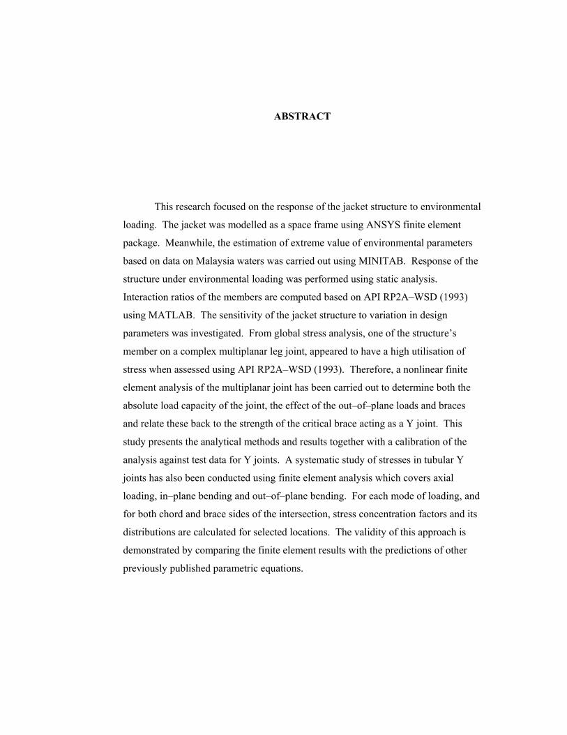
ABSTRACT
This research focused on the response of the jacket structure to environmental
loading. The jacket was modelled as a space frame using ANSYS finite element
package. Meanwhile, the estimation of extreme value of environmental parameters
based on data on Malaysia waters was carried out using MINITAB. Response of the
structure under environmental loading was performed using static analysis.
Interaction ratios of the members are computed based on API RP2A–WSD (1993)
using MATLAB. The sensitivity of the jacket structure to variation in design
parameters was investigated. From global stress analysis, one of the structure’s
member on a complex multiplanar leg joint, appeared to have a high utilisation of
stress when assessed using API RP2A–WSD (1993). Therefore, a nonlinear finite
element analysis of the multiplanar joint has been carried out to determine both the
absolute load capacity of the joint, the effect of the out–of–plane loads and braces
and relate these back to the strength of the critical brace acting as a Y joint. This
study presents the analytical methods and results together with a calibration of the
analysis against test data for Y joints. A systematic study of stresses in tubular Y
joints has also been conducted using finite element analysis which covers axial
loading, in–plane bending and out–of–plane bending. For each mode of loading, and
for both chord and brace sides of the intersection, stress concentration factors and its
distributions are calculated for selected locations. The validity of this approach is
demonstrated by comparing the finite element results with the predictions of other
previously published parametric equations.

ABSTRAK
Penyelidikan ini bertumpu kepada tindak balas struktur luar pantai terhadap
beban persekitaran. Permodelan struktur luar pantai yang terdiri daripada kerangka
dilakukan dengan menggunakan kaedah unsur terhingga ANSYS. Selain itu,
anggaran nilai parameter persekitaran yang ekstrim berdasarkan data di perairan
Malaysia dilakukan dengan menggunakan MINITAB. Tindak balas struktur luar
pantai terhadap beban persekitaran dianalisis secara statik. Nisbah beban terhadap
kapasiti elemen dikira berdasarkan API RP2A–WSD (1993) dengan MATLAB.
Kepekaan struktur luar pantai terhadap parameter yang digunakan dalam rekabentuk
dikaji. Daripada analisis tegasan, salah satu elemen yang terdapat pada sambungan
kaki struktur didapati mempunyai nilai nisbah penggunaan tegasan yang tinggi
apabila disemak dengan API RP2A–WSD (1993). Oleh itu, analisis kaedah unsur
terhingga tak linear sambungan multiplanar dijalankan untuk menentukan kedua–dua
nilai mutlak kapasiti beban pada sambungan, kesan beban dan cabang luar planar dan
mengaitkan semula kepada kekuatan elemen kritikal yang berfungsi sebagai
sambungan Y. Kajian ini mempersembahkan kaedah analitikal dan output bersama
dengan kalibrasi yang dilakukan terhadap data ujikaji sambungan Y. Kajian tegasan
yang sistematik juga dilakukan ke atas sambungan Y dengan menggunakan analisis
kaedah unsur terhingga yang meliputi beban paksi, momen dalam planar dan momen
luar planar. Bagi setiap jenis beban, dan untuk kedua–dua belah pertemuan
sambungan, faktor penumpuan tegasan dikira untuk lokasi yang tertentu. Kesahan
metodologi ini dipersembahkan dengan membuat perbandingan di antara output
daripada analisis kaedah unsur terhingga dengan persamaan parametrik yang
diterbitkan oleh penyelidik lain.

TABLE OF CONTENTS
CHAPTER TITLE PAGE
DECLARATION ii
ACKNOWLEDGEMENT iii
ABSTRACT iv
ABSTRAK v
TABLE OF CONTENTS vi
LIST OF TABLES xii
LIST OF FIGURES xv
LIST OF SYMBOLS xxi
LIST OF APPENDICES xxv
1 INTRODUCTION 1
1.1 Research Significance 1
1.2 Research Objectives 2
1.3 Outline of Thesis 3

2 LITERATURE REVIEW PART I:
ENVIRONMENTAL LOADING ON FIXED
OFFSHORE STRUCTURES 6
2.1 Introduction 6
2.2 Historical Development of Oil and Gas in
Malaysia 7
2.3 Historical Development of Offshore
Structures 8
2.4 Classification of Offshore Structures 9
2.4.1 Fixed Structures 10
2.4.2 Mobile Structures 11
2.4.3 Compliant Structures 12
2.5 Type of Loading on Offshore Structures 13
2.6 Environmental Loading 14
2.6.1 Design Environmental Conditions 16
2.6.1.1 Oceanographic Conditions 17
2.6.1.2 Wind Conditions 18
2.6.1.3 Estimation of Extreme Values 19
2.6.2 Evaluation of Water Particle Motion 26
2.6.2.1 Wave Theories 27
2.6.2.2 Wave–Current Interaction 38
2.6.3 Evaluation of External Loads 41
2.6.3.1 Wave Force 41
2.6.3.2 Transverse Force 44
2.6.3.3 Wind Force 46
2.7 Summary 48
3 LITERATURE PART II: TUBULAR JOINTS 68
3.1 Introduction 68
3.2 Brief History of Tubular Joints 69
3.3 Classification of Tubular Joints 70

3.4 Joint Types 71
3.5 Behaviour of Tubular Joint under Operating
Loads 72
3.6 Stress Analysis of Tubular Joints 75
3.6.1 Thin–Shell Finite Elements 76
3.6.2 Three–Dimensional Isoparametric
Finite Elements 78
3.6.3 Nonlinear Analysis 79
3.7 Behaviour of Tubular Joint under Static Loads 80
3.8 Fatigue Performance of Tubular Joints 82
3.8.1 Stress Concentration Factor Equations 83
3.8.2 S–N Curves 91
3.8.3 Palmgren–Miner Cumulative Damage
Rule 92
3.9 Summary 93
4 STRUCTURAL MODEL AND
ENVIRONMENTAL CONDITIONS AT
SOTONG FIELD 101
4.1 Introduction 101
4.2 Model of Jacket Structure 101
4.2.1 Description of the Structure 102
4.2.2 Element of Jacket Structure 103
4.3 Environmental Conditions at Sotong Field 105
4.3.1 Estimation of Extreme Wave and
Associated Period 105
4.3.1.1 Basic Data 106
4.3.1.2 Statistical Analysis of
Extreme Significant Wave
Height 106
4.3.1.3 Maximum Individual Wave
Height and Associated Period 108
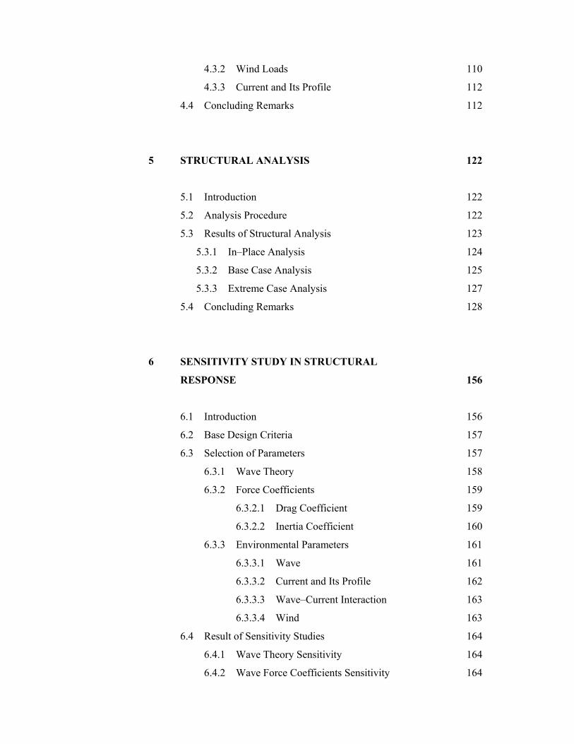
4.3.2 Wind Loads 110
4.3.3 Current and Its Profile 112
4.4 Concluding Remarks 112
5 STRUCTURAL ANALYSIS 122
5.1 Introduction 122
5.2 Analysis Procedure 122
5.3 Results of Structural Analysis 123
5.3.1 In–Place Analysis 124
5.3.2 Base Case Analysis 125
5.3.3 Extreme Case Analysis 127
5.4 Concluding Remarks 128
6 SENSITIVITY STUDY IN STRUCTURAL
RESPONSE 156
6.1 Introduction 156
6.2 Base Design Criteria 157
6.3 Selection of Parameters 157
6.3.1 Wave Theory 158
6.3.2 Force Coefficients 159
6.3.2.1 Drag Coefficient 159
6.3.2.2 Inertia Coefficient 160
6.3.3 Environmental Parameters 161
6.3.3.1 Wave 161
6.3.3.2 Current and Its Profile 162
6.3.3.3 Wave–Current Interaction 163
6.3.3.4 Wind 163
6.4 Result of Sensitivity Studies 164
6.4.1 Wave Theory Sensitivity 164
6.4.2 Wave Force Coefficients Sensitivity 164

6.4.3 Wave Height Sensitivity 165
6.4.4 Wave Period Sensitivity 166
6.4.5 Current Velocity Sensitivity 166
6.4.6 Wave–Current Interaction Sensitivity 167
6.4.7 Wind Load Sensitivity 167
6.5 Concluding Remarks 167
7 ULTIMATE STRENGTH ASSESSMENT OF
A MULTIPLANAR JOINT 179
7.1 Introduction 179
7.2 Joint Configuration, Loading and Strength
Definitions 180
7.3 Scope of the Analytical Investigation 180
7.4 Finite Element Model of Multiplanar Joint 181
7.5 Analysis of Results 184
7.5.1 Complete Joint–All Braces Loaded 185
7.5.2 Complete Joint–Only Brace 251 Loaded 186
7.5.3 Y Joint–Brace 251 Subjected to All
Six Load Components 187
7.5.4 Y Joint–Brace 251 Subjected to
Axial Load Only 187
7.6 Comparison of Results 188
7.7 Concluding Remarks 189
8 STRESS CONCENTRATION FACTORS FOR
Y JOINT 202
8.1 Introduction 202
8.2 Joint Configuration 203
8.3 Finite Element Model of Y Joint 203
8.4 Results of Stress Analysis 205

8.5 Comparison of Results 207
8.6 Concluding Remarks 209
9 DISCUSSIONS 219
9.1 Introduction 219
9.2 Environment Modelling 219
9.3 Structural Analysis 221
9.4 Sensitivity of Jacket Structure 222
9.5 Strength Assessment of a Multiplanar Joint 223
9.6 Stress Concentration Factors for Y Joint 224
10 CONCLUSIONS AND SUGGESTIONS FOR
FUTURE RESEARCH 226
10.1 Introduction 226
10.2 Conclusions 226
10.3 Suggestions for Future Research 228
REFERENCES 230
APPENDIX A – Structural Model 238
APPENDIX B – Structural Configuration 247

LIST OF TABLES
TABLE NO. TITLE PAGE
2.1 Existing platforms water depth distribution 49
2.2 Planned platforms water depth distribution 49
2.3 Selected probability distributions 50
2.4 Results of linear wave theory 51
2.5 Shallow and deep water approximation to
linear wave theory 52
2.6 Results of Stokes fifth–order wave theory 53
2.7 The coefficients for Stokes fifth–order
wave theory 54
2.8 Values of hydrodynamic coefficient for
circular cylinders 55
3.1 Basic dimensions for simple joint 94
3.2 Non–dimensional geometric parameter for
tubular joint 94
4.1 Data on significant wave height at the Sotong
field for the years 1941–1990 113
4.2 Comparison of goodness of fit test for various
distributions (significant wave height) 113
4.3 Data on wind speed at the Sotong field for the
years 1941–1990 114
4.4 Comparison of goodness of fit test for various
distributions (wind speed) 114

4.5 Design specification applied for the base case
and extreme case model 115
5.1 Base shear and overturning moment for
in–place analysis 129
5.2 Base shear and overturning moment for base
case analysis 129
5.3 Selected structural elements for ultimate strength
analysis 129
5.4 Stress utilisation ratio for selected element at
node I and node J (base case) 130
5.5 Base shear and overturning moment for extreme
case analysis 131
5.6 Stress utilisation ratio for selected element at
node I and node J (extreme case) 132
6.1 Base design criteria 169
6.2(a) Static strength sensitivity studies (base case) 170
6.2(b) Static strength sensitivity studies (extreme case) 171
6.3 Normalised maximum base shear 172
6.4 Normalised maximum overturning moment 173
7.1 Geometry of the multiplanar joint 190
7.2 Loads in member local axis system extracted
from global analysis of jacket structure 190
7.3 Ratio of ultimate axial load to ultimate load
capacity of analysis 4 191
8.1 Stress concentration factors values at crowns,
saddle and hot–spot on brace and chord 210
8.2 Comparison between results of meshes to
show extent of convergence 210
8.3 Comparison of predicted stress concentration
factors for axial loading 211
8.4 Comparison of predicted stress concentration
factors for in–plane bending 211
8.5 Comparison of predicted stress concentration
factors for out–of–plane bending 212

9.1 Comparison of typical design wave parameter
for Malaysia’s water (100–year return period) 220

LIST OF FIGURES
FIGURE NO. TITLE PAGE
2.1 Jacket platform 56
2.2 Gravity platform 57
2.3 Typical jack–up rig 58
2.4 Typical semi–submersible vessel 59
2.5 Guyed tower 60
2.6 Tension leg platform (TLP) 61
2.7 Articulated tower 62
2.8 Definition sketch for a progressive wave train 62
2.9 Range of wave theories giving the best fit to
the dynamic free surface boundary condition 63
2.10 Ranges of suitability for various wave theories
as suggested by Le Mehaute 63
2.11 Various methods of combining a current profile
with the variation in instantaneous water depth
due to wave action 64
2.12 Classification of wave force calculation methods 65
2.13 Definition sketch for wave forces on cylinder 65
2.14 DC versus KC number for various values of Re
and frequency parameter ( KCRe=β ) 66
2.15 MC versus KC number for various values of Re
and frequency parameter ( KCRe=β ) 66
2.16 Flow patterns at various values of KC 67
3.1 Typical tubular joints 95
3.2 Stiffened joint 96
3.3 Typical jacket framing configurations 97
3.4 Notation for joint configurations 97
3.5 Weld defects 98
3.6 Punching shear concept 98
3.7 Finite element mesh and stress contours for a
K joint 99
3.8 Reserve strength of a tubular connection 99
3.9 Empirical design curve for punching shear 100
3.10 Fatigue S–N curve 100
4.1 Structural model 116
4.2 PIPE 59 immersed pipe 116
4.3 PIPE 59 velocity profile for wave–current
interaction 117
4.4 Element load vector effects 117
4.5 Extreme Value distribution for significant
wave height 118
4.6 Log–Normal distribution for significant
wave height 118
4.7 Weibull 2–Parameter distribution for
significant wave height 119
4.8 Extreme Value distribution for wind speed 119
4.9 Log–Normal distribution for wind speed 120
4.10 Weibull 2–Parameter distribution for wind
speed 120
4.11 Current velocity profile 121
5.1 Environmental load on offshore structure 133
5.2 Global coordinate system of the structure 133
5.3 Stress utilisation ratio for in–place analysis
(nodes I and J) 134
5.4 Variation of base shear and overturning moment
with wave phase angle for base case 135

5.5(a) Stress utilisation ratio at nodes I and J for base
case (wave phase angle: 0, 360) 136
5.5(b) Stress utilisation ratio at nodes I and J for base
case (wave phase angle: 45) 137
5.5(c) Stress utilisation ratio at nodes I and J for base
case (wave phase angle: 90) 138
5.5(d) Stress utilisation ratio at nodes I and J for base
case (wave phase angle: 135) 139
5.5(e) Stress utilisation ratio at nodes I and J for base
case (wave phase angle: 180) 140
5.5(f) Stress utilisation ratio at nodes I and J for base
case (wave phase angle: 225) 141
5.5(g) Stress utilisation ratio at nodes I and J for base
case (wave phase angle: 270) 142
5.5(h) Stress utilisation ratio at nodes I and J for base
case (wave phase angle: 315) 143
5.6 Variation of stress utilisation ratio at nodes I
and J for selected elements with wave phase
angle (base case) 144
5.7 Variation of base shear and overturning moment
with wave phase angle for extreme case 145
5.8(a) Stress utilisation ratio at nodes I and J for
extreme case (wave phase angle: 0, 360) 146
5.8(b) Stress utilisation ratio at nodes I and J for
extreme case (wave phase angle: 45) 147
5.8(c) Stress utilisation ratio at nodes I and J for
extreme case (wave phase angle: 90) 148
5.8(d) Stress utilisation ratio at nodes I and J for
extreme case (wave phase angle: 135) 149
5.8(e) Stress utilisation ratio at nodes I and J for
extreme case (wave phase angle: 180) 150
5.8(f) Stress utilisation ratio at nodes I and J for
extreme case (wave phase angle: 225) 151

5.8(g) Stress utilisation ratio at nodes I and J for
extreme case (wave phase angle: 270) 152
5.8(h) Stress utilisation ratio at nodes I and J for
extreme case (wave phase angle: 315) 153
5.9 Variation of stress utilisation ratio at nodes I
and J for selected elements with wave phase
angle (extreme case) 154
5.10 Percentage difference in stress utilisation ratio
at nodes I and J for extreme case compared to
the base case (wave phase angle: 45) 155
6.1 Variation of base shear and overturning moment
with wave height for base case and extreme case 174
6.2 Variation of base shear and overturning moment
with wave period for base case and extreme case 175
6.3 Variation of base shear and overturning moment
with depth average current for base case and
extreme case 176
6.4 Base shear and overturning moment sensitivity
for base case 177
6.5 Base shear and overturning moment sensitivity
for extreme case 178
7.1 Configuration of a typical multiplanar joint on
jacket structure 192
7.2 General loading of structural element 193
7.3 Finite element mesh of multiplanar joint 193
7.4 Finite element model of multiplanar joint 194
7.5 Stress/strain relationship 194
7.6 Nodes at intersection of chord and brace 251 195
7.7 Location of elements on chord and brace 251 195
7.8 Elements on chord (only brace 251 shown) 196
7.9 Elements on chord (only brace 251 shown) 196
7.10(a) Development of stresses around chord (joint
with all braces loaded) 197

7.10(b) Deformation of chord below brace 251 (joint
with all braces loaded) 197
7.11(a) Development of stresses around chord (joint
with only brace 251 loaded) 198
7.11(b) Deformation of chord below brace 251 (joint
with only brace 251 loaded) 198
7.12(a) Displacement at node 5478 (Y joint with brace
251 subjected to all load components) 199
7.12(b) Deformation of chord below brace 251 (Y joint
with brace 251 subjected to all load components) 199
7.13(a) Displacement at node 5478 (Y joint with brace
subjected to axial load) 200
7.13(b) Deformation of chord below brace 251 (Y joint
with brace subjected to axial load) 200
7.14 Comparison of Y joint finite element (FE) result
with test database 201
8.1 Subdivision of the tubular joint into a number of
regions suitable for mesh generation 213
8.2 Typical example of finite element mesh used to
model tubular joint 213
8.3 Details of modes of loading used for finite
element joint analyses 213
8.4 Comparison of SCFs distribution between chord
and brace under axial loading 214
8.5 Comparison of SCFs distribution between chord
and brace under in–plane bending 214
8.6 Comparison of SCFs distribution between chord
and brace under out–of–plane bending 215
8.7 Comparison of SCFs distribution between UCL
equations and FE data for axial loading (chord) 215
8.8 Comparison of SCFs distribution between UCL
equations and FE data for axial loading (brace) 216

8.9 Comparison of SCFs distribution between UCL
equations and FE data for in–plane bending
(chord) 216
8.10 Comparison of SCFs distribution between UCL
equations and FE data for in–plane bending
(brace) 217
8.11 Comparison of SCFs distribution between UCL
equations and FE data for out–of–plane bending
(chord) 217
8.12 Comparison of SCFs distribution between UCL
equations and FE data for out–of–plane bending
(brace) 218
LIST OF SYMBOLS
na – Normal particle acceleration vector
AM – Annual maxima
BS – Base shear
c – Wave celerity
bC – Buoyancy coefficient
DC – Drag coefficient
LC – Lift coefficient
MC – Inertia coefficient
WC – Wind drag coefficient
WLC – Wind drag coefficient for long member
WSC – Wind drag coefficient for short member
d – Water depth
D – Diameter
BD – Brace outer diameter
CD – Chord outer diameter
eD – Outside diameter of the pipe with insulation
PMD – Cumulative damage ratio
E – Young’s modulus of steel
E – Mean square
pE – Encounter probability
EDF – Empirical distribution function
af – Nominal axial stress

bf – Nominal bending stress
Df – Drag force
If – Inertia force
Lf – Lift force
Sf – Frequency of vortex
F – Forces
FE – Finite element
FT–I – Fisher–Tippett Type I
FT–II – Fisher–Tippett Type II
FT–III – Fisher–Tippett Type III
F(x) – Cumulative probability distribution
bF – Allowable bending stress
WF – Wind force
yF – Yield stress
g – Gravity
G – Gust factor
H – Wave height
SH – Significant wave height
maxH – Maximum individual wave height
I – Turbulence intensity
IPB – In–plane bending
ID – Initial distribution
k – Wave number
KC – Keulegan–Carpenter number
L – Wave length
CL – Chord length
fL – Design lifetime of a structure
ML – Member length
M – Moments
OPB – Out–of–plane bending
OTM – Overturning moment

POT – Peak over threshold
( )XP – Probability of non–exceedance
( )xXP < – Probability that a randomly chosen observation X will
be below x
Q – Bernoulli constant
Q(X) – Probability of exceedance
Re – Reynolds number
S – Strouhal number
SS – Wave steepness
WS – Frontal area (facing the wind)
SCFs – Stress concentration factors
SWL – Still water level
t – Time
T – Wave period
RT – Return period
zT – Mean zero–crossing period associated with the extreme
storm
assT – Period associated with the design wave
u – Horizontal water particle velocity
nu – Normal relative particle velocity
tu – Tangential relative particle velocity
U – Steady velocity
CU – Current velocity
GU – Gust wind
WU – Wind speed
pV – Punching shear stress
w – Vertical water particle velocity
BWT – Brace wall thickness
CWT – Chord wall thickness
Z – Statistical constant
α – Ratio of chord length to chord radius

β – Frequency parameter
δ – Ratio of the brace diameter to chord diameter
ε – Perturbation parameter
φ – Velocity potential
ϕ – Angle between brace and chord
γ – Ratio of chord radius to the chord wall thickness
η – Free surface elevation
π – Pi
θ – Wave phase angle
ϑ – Angle around the intersection of joint
ρ – Density of steel
aρ – Air density
wρ – Water density
σ – Standard deviation
τ – Ratio of the wall thickness of the brace to that of the
chord
ω – Angular frequency
aω – Apparent angular frequency
rω – Relative angular frequency
ψ – Stream function

LIST OF APPENDICES
APPENDIX TITLE PAGE
A Structural Model 238
B Structural Configuration 247

CHAPTER 1
INTRODUCTION
1.1 Research Significance
The demand for exploration and production of oil and gas has grown
worldwide during the past few decades in spite of its periodic down turns. As a
consequence of this general search to explore and exploit offshore energy resources,
new innovations and developments have taken place in structural form, equipment
technology, inspection, repair methodologies and economic field utilisation. Oil and
gas will continue as the most important source of energy remainder of this century
and well into the next century.
With reference to offshore production facilities, any structures employed
must perform satisfactorily under service conditions while safely enduring extreme
environmental events. Environmental loads such as wind, wave, tide, current and
marine fouling are well known to be major contributor to the loading experienced by
any offshore structures. In addition, ice and earthquake are important in some
geographical location. Being of random in nature, the environmental loads chosen as
design loads must not less than the most probable severest load in a time period of
100 years. The ability to predict accurately the extreme environmental loading

remains an important factor in the continued safe and economic exploitation of the
hydrocarbon reserves.
Secondly, the sensitivity of the structural response due to the changes in
design parameters is still not well understood. The effect of variations in the design
parameters is dependent on both the range of values considered and sensitivity of
structural design to such variations. In this study, analyses are carried out to
investigate the sensitivity of the structure response to the variations in design
parameters.
One of the features of fixed offshore structures is the problem of tubular joint
design. A global stress analysis of the overall structure resolves applied gravity
loads and environmental loads into nominal axial and bending stresses in the various
members. If local scale stress analysis is performed on tubular connection, the hot–
spot stresses near the welded intersection are found several times higher than
nominal, often exceeding yield and may cause it to collapse. The local analysis may
involve rigorous shell theory, finite element analysis or experimental stress analysis.
In this study, finite element analysis has been used to investigate local stress and
ultimate static strength of tubular joint.
1.2 Research Objectives
The main objectives of the research presented in this thesis are:
a) To develop an environmental loading model for typical jacket structure in
Malaysia’s water.

b) To study the effects of variations in design parameters on the jacket structure.
c) To determine the load capacity of a multiplanar joint.
d) To perform stress analysis on Y joint.
1.3 Outline of Thesis
This thesis consists of nine chapters begin with the introductory chapter. The
literature reviews are divided into two chapters, which is Chapter Two and Chapter
Three. The division of the literature review is essential to give the readers a better
understanding of the research topic as both chapters discuss two different topics in
depth.
Chapter Two describes in detail the methods which are available to translate a
definition of environmental conditions into the resultant steady and time dependent
forces on the structure. This chapter is concerned with describing and developing
methods of calculating these forces for fixed offshore structures.
Chapter Three discusses the behaviour of tubular joints under operating loads
and static loads. The punching shear is used as a viewpoint from which to examine
various approaches to stress analysis of tubular joints, such as thin–shell finite
elements and three dimensional isoparametric finite elements.
Chapter Four describes the structural model of a typical four legged jacket
structure and the modelling of the environmental parameters where the structure is

situated. The statistical analysis of extreme is used to estimate extreme
environmental loading experienced by the structure.
Chapter Five studies the response of the jacket structure under extreme
environmental loading conditions. Analysis procedures are discussed and the
selections of critical member for further analysis are also discussed. Results from the
structural simulation studies in term of base shear and overturning moment, and the
utilisation ratio of structural members are presented.
Chapter Six investigates the sensitivity of jacket structure to uncertainties in
parameters used in design. The parameters which considered in this study are wave
theory, force coefficients, wave height and period, current and its profile, wave–
current interaction and wind. The design parameters were varied one at a time,
within appropriate ranges, and the effects of parameters which were considered to be
the measures of static strength was calculated.
In Chapter Seven, a series of nonlinear finite element analysis was carried out
to determine both the absolute load capacity of the joint, the effect of the out–of–
plane loads and braces and relate these back to the strength of the critical brace
acting as Y joint. This study presents the analytical methods and results together
with a calibration of the analysis against test data for Y joints.
Chapter Eight describes the modelling of Y joint using finite element and is
subjected to simple loadings of the axial, in–plane bending and out–of–plane bending
types, applied separately to the joints. The stress concentration factors and its
distributions obtained from the analyses were compared with the predictions of other
previously published parametric equations.

Chapter Nine presents the overall discussion on the research works which
emphasises on the environmental modelling, structural analysis, sensitivity of jacket
structure, strength assessment of a multiplanar joint and stress concentration factor
for Y joint.
The thesis is concluded in Chapter Ten, which comprises of the summary of
the works and recommendations for further research.

REFERENCES
Allender, J.H. and Petrauskas, C. (1987). Measured and Predicted Wave Plus Current
Loading on a Laboratory–Scale, Space Frame Structure. Proceedings of the 19th
Annual Offshore Technology Conference. April 27–30. Houston: OTC, 143–151.
American Petroleum Institute (1993). Recommended Practice for Planning,
Designing and Constructing Fixed Offshore Platforms–Working Stress Design.
20th ed. Washington: API.
American Welding Society D1.1–86 (1986). Structural Welding Code. 10th ed.
Miami: AWS.
Arief, S. and Wells, R. (1985). Report on the Malaysian Petroleum Industry.
Australia: Rosecons.
Atkins Oil and Gas Engineering Ltd. (1988). Sensitivity of Shallow Water Jacket
Structures to Uncertainties in Environmental Loading. London: HMSO.
Barltrop, N. P. D., Mitchell, G. M. and Attkins, J. B. (1990). Fluid Loading on Fixed
Offshore Structures. London: Department of Energy.
Bea, R.G. and Lai, N.W. (1978). Hydrodynamic Loadings on Offshore Structures.
Proceedings of the 10th Annual Offshore Technology Conference. May 8–11.
Houston: OTC, 155–168.
Borgman, L.E. (1963). Risk Criteria. Journal of Waterways and Harbors Division.
89(WW3): 1–35.

Carter, D. J. T. and Challenor, P. G. (1983). Methods of Fitting the Fisher–Tippett
Type 1 Extreme Value Distribution. Ocean Engineering. 10(3): 191–199.
Chakrabarti S.K. (1987). Hydrodynamics of Offshore Structures. Boston:
Computational Mechanics Publications.
Chakrabarti, S. K. (1990). Nonlinear Methods in Offshore Engineering. New York:
Elsevier.
Dalrymple, R. A. (1974). Models for Nonlinear Water Waves on Shear Currents.
Proceedings of the 6th Annual Offshore Technology Conference. May 6–8.
Houston: OTC, 843–856.
Dawson, T. H. (1983). Offshore Structural Engineering. Englewood Cliffs: Prentice
Hall.
Dean, R.G. (1965). Stream Function Representation of Nonlinear Ocean Waves.
Journal of Geophysical Research. 70(18): 4561–4572.
Dean, R. G. (1970). Relative Validities of Water Wave Theories. Journal of
Waterways, Harbors and Coastal Engineering Division. 96(WWI): 105–119.
Driver, D. B., Borgman, L. E. and Bole, J. B. (1994). Typhoon Wind, Wave and
Current Directionality in the South China Sea. Proceedings of the 26th Annual
Offshore Technology Conference. May 2–5. Houston: OTC, 359–365.
Dutta, D. (1996). Parameters Influencing the Stress Concentration Factors in Joints
in Offshore Structure. In: Dover, W. D. and Madhava Rao, A. G. eds. Fatigue in
Offshore Structures (Volume 1). Rotterdam: A. A. Balkema. 77–128.
Efthymiou, M. and Durkin, S. (1985). Stress Concentrations in T/Y and Gap/Overlap
K–Joints. Proceedings of the 4th Conference on Behaviour of Offshore Structures.
July 1–5. Delft: BOSS, 429–440.

Efthymiou, M. and Graham, C.G. (1990). Environmental Loading on Fixed Offshore
Platforms. Environmental Forces on Offshore Structures and their Prediction.
November 28–29. Netherlands: SUT, 293–320.
Gaythwaite, J. (1981). The Marine Environment and Structural Design. New York:
Van Nostrand Reinhold Company.
Graff, W. J. (1981). Introduction to Offshore Structures: Design, Fabrication and
Installation. Houston: Gulf Publishing Company.
Gringorten, I. (1963). A Plotting Rule for Extreme Probability Paper. Journal of
Geophysical Research. 68(3): 813–814.
Gudmestad, O. T. and Karunakaran, D. (1990). Wave Current Interaction.
Environmental Forces on Offshore Structures and Their Prediction. November
28–29. Netherlands: SUT, 81–110.
Guedes Soares, C. and Henriques, A. C. (1996). Statistical Uncertainty in Long–
Term Distributions of Significant Wave Height. Journal of Offshore Mechanics
and Artic Engineering. 118: 284–291.
Guedes Soares, C. and Scotto, M. (2001). Modelling Uncertainty in Long–Term
Predictions of Significant Wave Height. Ocean Engineering. 28: 329–342.
Gumbel, E.J. (1958). Statistics of Extremes. New York: Columbia University Press.
Haring, R. E. and Heideman, J. C. (1980). Gulf of Mexico Rare Wave Return Periods.
Journal of Petroleum Technology. 32(1): 35–47.
Healy, B. E. and Buitrago, J. (1994). Extrapolation Procedures for Determining SCFs
in Mid–Surface Tubular Joint Models. In: Grundy, P., Holgate, A. and Wong, B.
eds. Tubular Structures (VI). Rotterdam: A. A. Balkema. 651–659.

Hellier, A. K., Connolly, M. P. and Dover, W. D. (1990a). Stress Concentration
Factors for Tubular Y– and T–Joints. International Journal of Fatigue. 12(1):
13–23.
Hellier, A. K., Connolly, M. P., Kare, R.F. and Dover, W. D. (1990b). Prediction of
the Stress Distribution in Tubular Y– and T–Joints. International Journal of
Fatigue. 12(1): 25–33.
Hogben, N. (1976). Wave Loads on Structures. Proceedings of the 1st International
Conference on Behaviour of Offshore Structures. August 2–5. Norwegian: BOSS,
187–219.
Irons, B. M. (1976). The Semiloof Shell Element. In: Ashwell, D. G. and Gallagher,
R. H. eds. Finite Elements for Thin Shells and Curved Members. London: Wiley.
197–222.
Isaacson, M. de St. Q. and Maull, D. J. (1976). Transverse Forces on Vertical
Cylinders in Waves. Journal of Waterways, Harbors and Coastal Engineering
Division. 102(WW1): 49–60.
Knight, R. M. and Daniel, J. J. S. (1993). World Trends in Major Offshore Structures
1970–1999. Proceeding of the 3rd International Conference on Offshore 93:
Installation of Major Offshore Structures and Equipments. February 17–18.
London: IMarE/RINA, 17–23.
Kohnke, P. (1992). ANSYS User’s Manual for Revision 5.0, Volume IV: Theory.
Houston: Swanson Analysis Systems, Inc.
Lalani, M. (1992). Developments in Tubular Joints Technology for Offshore
Structures. Proceedings of the 2nd International Offshore and Polar Engineering
Conference. June 14–19. San Francisco: ISOPE, 260–274.
Leick, R. D. and Potvin, A. B. (1977). Automated Mesh Generation for Tubular Joint
Stress Analysis. International Journal Computers and Structures. 7(1): 73–91.

Le Mehaute, B. (1976). An Introduction to Hydrodynamics and Water Waves.
Dusseldorf: Springer–Verlag.
Liaw, C. Y., Litton, R. W. and Reimer, R. B. (1976). Improved Finite Elements for
Analysis of Welded Tubular Joints. Proceedings of 8th Annual Offshore
Technology Conference. May 3–6. Houston: OTC, 267–282.
Lloyd’s Register of Shipping (1988). Sensitivity of Fixed Offshore Platforms to
Uncertainties in Design Parameters. London: HMSO.
Madhava Rao, A. G. and Raghava, G. (1996). An Overview of Offshore Structures.
In: Dover, W. D. and Madhava Rao, A. G. eds. Fatigue in Offshore Structures
(Volume 1). Rotterdam: A. A. Balkema. 1–20.
Marshall, P. W. and Toprac, A. A. (1974). Basis for Tubular Joint Design. Welding
Journal. 53(5): 192s–201s.
Marshall, P. W. (1986). Tubular Joint Design. In: McClelland, B and Reifel, M. D.
eds. Planning and Design of Fixed Offshore Platforms. New York: Van Nostrand
Reinhold Company. 624–691.
Morison, J. R., O’Brien, M. P., Johnson, J. W. and Schaaf, S. A. (1950). The Force
Exerted by Surface Waves on Piles. Petroleum Transactions. 189: 149–157.
Muga, B. J. and Wilson, J. F. (1970). Dynamic Analysis of Ocean Structures. New
York: Plenum Press.
Muir, L. R. and El–Shaarawi, A. H. (1986). On the Calculation of Extreme Wave
Heights: A Review. Ocean Engineering. 13(1): 93–118.
Pagrut, P. and Deo, M. C. (1992). Extreme Wave Height Estimates. Proceedings of
the 2nd International Offshore and Polar Engineering Conference. June 14–19.
San Francisco: ISOPE, 186–193.

Patel, M. H. (1990). Offshore Structures. In: Morgan, N. ed. Marine Technology
Reference Book. London: Butterworth.
Peregrine, D. H. (1976). Interaction of Water Waves and Currents. Advances in
Applied Mechanics. 16: 9–117.
Petrauskas, C. and Aagaard, P. M. (1971). Extrapolation of Historical Storm Data for
Estimating Design–Wave Heights. Society of Petroleum Engineers Journal.
11(1): 23–37.
Potvin, A. B., Kuang, J. G., Leick, R. D. and Kahlick, J. L. (1977). Stress
Concentration in Tubular Joints. Journal of Petroleum Technology. 29: 287–299.
Puthli, R. S., van Foeken, R. J. and Romeijn, A. (1996). Guidelines on the
Determination of Stress Concentration Factors of Circular and Rectangular
Hollow Section Joints. In: Dover, W. D. and Madhava Rao, A. G. eds. Fatigue in
Offshore Structures (Volume 1). Rotterdam: A. A. Balkema. 129–154.
Ramachandra Murthy, D. S. (1996). Static and Fatigue Strength of Steel Tubular
Joints. In: Dover, W. D. and Madhava Rao, A. G. eds. Fatigue in Offshore
Structures (Volume 1). Rotterdam: A. A. Balkema. 311–333.
Reeves, H. W. (1975). An Overview of the Offshore Platform Industry. New England
Section: SNAME.
Rodenbusch, G. and Kallstrom, C. (1986). Forces on a Large Cylinder in Random
Two–Dimensional Flows. Proceedings of 18th Annual Offshore Technology
Conference. May 5–8. Houston: OTC.
Sarpkaya, T. (1976). In–Line and Transverse Forces on Cylinders in Oscillatory
Flow at High Reynolds Numbers. Proceedings of 8th Annual Offshore
Technology Conference. May 3–6. Houston: OTC, 95–108.

Sarpkaya, T and Isaacson, M. (1981). Mechanics of Wave Forces on Offshore
Structures. New York: Van Nostrand Reinhold.
Sharma, J. N. and Grosskopf, W. G. (1994). Practical Considerations in Preparing
Extreme Wind, Wave, and Current Criteria. Proceedings of the 26th Annual
Offshore Technology Conference. May 2–5. Houston: OTC, 377–386.
Skjelbreia, L. and Hendrickson, J. A. (1961). Fifth–Order Gravity Wave Theory.
Proceedings of the 7th Conference on Coastal Engineering. Netherlands: ASCE,
184–196.
Smedley, P. and Fisher, P. (1991). Stress Concentration Factors for Simple Tubular
Joints. Proceeding of the 1st International Offshore and Polar Engineering
Conference. August 11–16. Edinburgh: ISOPE, 475-483.
Sterndorff, M. J., Velk, P. and Klinting, P. (1990). Coupled Experimental and
Analytical Investigation of Hydrodynamic Forces on a Jacket in Waves.
Environmental Forces on Offshore Structures and Their Prediction. November
28–29. Netherlands: SUT, 203–219.
Swanson Analysis System (1992). ANSYS User’s Manual for Revision 5.0, Volume
III: Elements. Houston: Swanson Analysis Systems, Inc.
Tucker, M. J. (1991). Waves in Ocean Engineering: Measurements, Analysis,
Interpretation. Chichester: Ellis Horwood Ltd.
Underwater Engineering Group (1985). Design of Tubular Joints for Offshore
Structures. London: UEG Publication UR33.
van Vledder, G. P. and Zitman, T. J. (1992). Design Waves: Statistics and
Engineering Practice. Proceedings of the 2nd International Offshore and Polar
Engineering Conference. June 14–19. San Francisco: ISOPE, 170–178.

Visser, W. (1974). On the Structural Design of Tubular Joints. Proceedings of the 6th
Annual Offshore Technology Conference. May 6–8. Houston: OTC, 881–894.
Vugts, J. H. (1979). A Review of Hydrodynamic Loads on Offshore Structures and
Their Formulation. Proceedings of the 2nd International Conference on
Behaviour of Offshore Structures. August 28–31. London: BOSS, 693–708.
Ward, J. K. and Billington, C. J. (1992). Strength Assessment of a Multiplanar Joint
in a North Sea Jacket Structure. Proceedings of the 2nd International Offshore
and Polar Engineering Conference. June 14–19. San Francisco: ISOPE, 369–376.
Watt, B. J. (1978). Basic Structural Systems–A Review of Their Design and Analysis
Requirements. In: Zienkiewicz, O. C., Lewis, R. W. and Stagg, K. G. eds.
Numerical Methods in Offshore Engineering. Chichester: Wiley. 1–42.
Wiegel, R. L. (1964). Oceanographical Engineering. New Jersey: Prentice Hall.
Wimpey Offshore (1989). Background to New Static Strength Guidance for Tubular
Joints in Steel Offshore Structures. London: HMSO.
Wordsworth, A. C. (1981). Stress Concentration Factors at K and KT Tubular Joints.
Conference on Fatigue in Offshore Structural Steels. February 24–25. London:
Thomas Telford Ltd, 59–66.
Yao, G. Q., Ding, B. C., Wang, J. Y. and Ma, Z. X. (1993). Statistic Analysis of
Wave Parameters for the China Sea. Proceedings of the 3rd International
Offshore and Polar Engineering Conference. June 6–11. Singapore: ISOPE, 22–
26.
Yura, J. A. and Zettlemoyer, N. (1980). Ultimate Capacity Equations for Tubular
Joints. Proceedings of the 12th Annual Offshore Technology Conference. May 5–
8. Houston: OTC, 113–126.


![[LECTURE] Design of Fixed Offshore Structures](https://static.fdocuments.in/doc/165x107/577cc0c81a28aba711911952/lecture-design-of-fixed-offshore-structures.jpg)