
NRW-FPGA-Based PRM System Qualification Project
63
Non-Proprietary Mark-up Version7 - Areas of proprietary information blanked I Document No. I FPG-DRT-C51-0006 Rev 10 NRW-FPGA-Based PRM System Qualification Project Document Title Actel's CDR Report CUSTOMER NAME None PROJECT NAME NRW-FPGA-Based PRM System Qualification Project ITEM NAME PRM Equipment ITEM NO. C51 JOB NO. FPG Issued by Approved Reviewed Prepared I by I by by Document Filing No. Monitoring System -• ° //'•d RS-5119187 Engineering Group "Z., 1 / . 2, 2c/ ae 6,20 TOSHIBA CORPORATION Nuclear Energy Systems & Services Div. 1/63
Transcript of NRW-FPGA-Based PRM System Qualification Project

Non-Proprietary Mark-up Version7- Areas of proprietary information blanked I
Document No. I FPG-DRT-C51-0006 Rev 10
NRW-FPGA-Based PRM System Qualification Project
Document Title Actel's CDR Report
CUSTOMER NAME NonePROJECT NAME NRW-FPGA-Based PRM
System Qualification ProjectITEM NAME PRM EquipmentITEM NO. C51JOB NO. FPG
Issued byApproved Reviewed Prepared
I by I by by Document Filing No.
Monitoring System -• ° //'•d RS-5119187Engineering Group "Z., 1 / . 2, 2c/ ae 6,20
TOSHIBA CORPORATION Nuclear Energy Systems & Services Div.
1/63
FPG-DRT-C51-0006 Rev.0
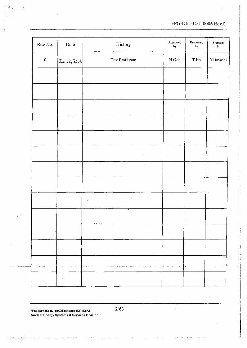
Approved Reviewed PreparedRev No. Date History by by by
0 -/2,o The first issue N.Oda T.Ito T.Hayashi
2/63TOSHIBA CORPORATIONNuclear Energy Systems & Services Division

FPG-DRT-C51-0006 Rev.0
Document Review Sheet
Items Results
Is the document complete? E1YES ONO UN/A
Are the descriptions correct? []YES UINO UN/A
Are the descriptions consistent? OYES FINO UN/A
Are the descriptions accurate? EJYES ONO U1N/A
Independent Reviewer(Sign & Date)
zi* /.• -
3/63TOSHIBA CORPORATIONNuclear Energy Systems & Services Division

FPG-DRT-C5 1-0006 Rev.0
Table of Contents
1.Introduction and Background ............................................................ 61. 1. Purpose ............................................................................... 61.2. Regulatory Guidance on Software Tools ........................................... 71.3. Overall Conclusions ................................................................. 81.4. Overall CDR Goals .................................................................. 91.5. [[.............. 101.6. [...... .. ............................................. 10
2. Cautions and Recommendations for Use .............................................. 152.1. E... .. .......................................................... 15,2.2. E... .. ......................................................... 15.2.3. fl....... .................................................. 162.4. E] .................................... 16
3. E[...... .............................................................. 193.1. FPGA Architecture Overview...................................................... 193.2. Introduction to the Software Tools ................................................ 20
3.3. E].................... 203.4. E. ............................................................... !...... 223.5. EE..... ............................................................. 233.6. E. . ..................................................................... 233.7. E. . ................................................................... 24
.3.8. E]........................... 253.9. EE. ....................................................................... 263.10. EE..... ......................................................... 26
4. E[...... ................................................................... 274.1. E.. .. ............................................................ 274.2. E].............................. 284.3. EE..... ...................................................... 324.4. E.... ........................................................... 344.5. E.... ........................................................... 364.6. EE...... ....................................................... 364.7. E............................................................ 364.8. EE... ............................................................. 384.9. E..............................E......................................... 38
TOSHIBA CORPORATION 4/63Nuclear Energy Systems & Services Division

FPG-DRT-CS 1-0006 Rev.0
5- [[........... .............................................. 405.1. .............................. 405.2. ]]......................... 405.3. E.... .. ..................................................... 415.4. EE.... ........................................................... 415.5. EE....................................................... 435.6. EE..... ...................................................... 435.7. ]]........E... 445.8. EE..... ...................................................... 495.9. EE..... ............................... :......................... 51
6. EE......... ........................................................ 536.1. Introduction......................................................................... 536.2. EE.......................... 546.3. 11....................56.4. EE........................... 55
7. Acronyms and Definitions .............................................................. 608. References ............................................................................... 63
5/63TOSHIBA CORPORATIONNuclear Energy Systems & Services Division

FPG-DRT-C51-0006 Rev.0
1. Introduction and Background
1.1. PurposeThis Critical Digital Review (CDR) supports the development of the Power Range NeutronMonitor (PRM) system by the Toshiba Corporation Nuclear Instrumentation and ControlSystems Department (NICSD). NICSD has previously designed and produced analogand computer-based systems for neutron monitoring in Japanese Boiling Water Reactors.They are currently enhancing their prototype Field Programmable Gate Array(FPGA)-based PRM system for the Japanese market, with the intent of eventuallymarketing this equipment to United States (US) nuclear plants. The advantages of anFPGA platform are that the programming execution is completely defined, simple(compared to computer-based systems), verifiable, and the technology is stable.
Engineers from the Control & Electrical Systems Design & Engineering Department(ICDD) of Toshiba Nuclear Energy Systems and Services Division (NED) performed aCDR on NICSD [[
]] The scope of the NICSD CDR (Reference 1) included reviews of thehardware architecture, application architecture, software configuration tools, and hardwareand software development and testing processes for the FPGA-based PRM system.During the CDR at NICSD, the CDR reviewers concluded that a review of the Acteltoolset was necessary. NICSD uses the Very High Speed Integrated Circuit (VHSIC)Hardware Description Language (VHDL) language to develop the FPGA logic. TheActel toolset provides the translation and transformation of that human-readable VHDLcode into digital logic circuits and embeds that logic in the FPGA. Accordingly, NEDengineers performed a CDR review of the Actel toolset and Actel development practiceswith assistance from MPR Associates engineers. [[
NED and NICSD have previously developed other products using FPGA technology.However, this is the first time they are using NICSD-developed Functional Elements (FEs).[[I
1]
NED and MPR engineers performed this CDR using the guidance provided by EPRITR-106439 (Reference 2) and EPRI TR-107339 (Reference 3). The USNRC hasaccepted EPRI TR-106439 as an acceptable means of assessing digital device quality fornuclear safety related applications. The reviews used the process evaluation guidance inthe USNRC Standard Review Plan, Branch Technical Position HICB-14 (Reference 4), and
6/63

FPG-DRT-C51-0006 Rev.0
the sections on design integrity from the Institute of Electrical and Electronics Engineers(IEEE) Standard 7-4.3.2-1993 (Reference 5).
Section 2 of this report summarizes the results of this CDR and provides recommendationsfor use of the Actel toolset in developing equipment for safety related applications.[[
1.2. Regulatory Guidance on Software ToolsIn order to use the Actel tools to develop FEs and logic for FPGAs, engineers from Toshibaand MPR Associates performed a CDR[[ .]]This CDR evaluated the Actel tools against the published US NRC regulatory expectations(Reference 4). NUREG-0800 states, in part, that:
"The plan should require that tools be qualified with a degree of rigor and level ofdetail appropriate to the safety significance of the software which is to be developedusing the tools. Methods, techniques, and tools that produce results that cannot beverified to an acceptable degree or that are not compatible with safety requirementsshould be prohibited, unless analysis shows that the alternative would be less safe."
I[[]] Rather Toshiba NICSD experts use the
tools to develop safety related systems. [[
7/63

FPG-DRT-C51-0006 Rev.0
[[
___ I _____ I _____
1.3. Overall ConclusionsThe CDR reviewers conclude that the programmed FPGAsappropriate for safety related use, provided that Toshibaprocesses evaluated in an earlier CDR of NICSD. [[
generated by these tools arecontinues to implement the
]] the CDR reviewers concludethat the compensatory actions taken by Toshiba provide an adequate level of assurance thatthe logic embedded in the FPGA performs the required functions, and that the processes
1I[[
]]
8/63

FPG-DRT-C51-0006 Rev.0
minimize the possibility of design errors in the logic. Thus, the CDR reviewers concludethat the Actel tools, used with the Toshiba processes, are acceptable for use in transforminghuman-readable source into digital logic embedded into FPGAs.
0[
1]
1.4. Overall CDR GoalsThis CDR supports the Toshiba NICSD CDR. This CDR evaluates the Actel toolset, aswell as the third-party tools provided with the toolset. The CDR reviewers recognize thatthe Actel and third-party toolsets are commercial, off-the-shelf (COTS) tools, designed forindustrial application. Toshiba can change neither the tool internals nor the processesused at the various tool vendors. [[
9/63

FPG-DRT-C51-0006 Rev.0
1.5. [[ ]Toshiba uses only the Actel Model A54SX32A and A54SX72A FPGAs. [[
Table 1-2 below lists the tools that are used in this process, with the versions evaluated andaccepted by NICSD at the time of the NICSD CDR. NICSD will establish a process foraccepting and documenting the acceptance of new tool versions when Actel releases thetools, based on data provided by Actel. As part of that process, NICSD will likely notadvance to a new toolset version if that version has no effect on their current, or previous,FPGA designs. If a new version corrects a design flaw or introduces a feature thatenhances FPGA reliability or improves the FPGA design, NICSD will follow their processfor evaluating the safety impact of the tool design flaw on already shipped equipment.R[
+ 4
4. .4
4. .4
1~ .4
1]
1.6. [[ ]]In order to focus the CDR review on just the portions of the Actel toolset in use at Toshiba,this section provides a brief explanation of the Toshiba NICSD process overlaid onto theActel tool data flow drawing, shown graphically in Figure 1-1. Figure 1-2 illustrates thecomplete Toshiba design process, as explained in the NICSD CDR (Reference 1).1[
10/63

FPG-DRT-C51-0006 Rev.0
Figure 1-1. Actel Tool Data Flow
1]
2. EDIF is an EIA standard. More about the standard can be found on their website http:iiVwvxedif.or,.. This
website is not being actively updated, but does provide useful reference information on EDIF.
11/63

FPG-DRT-C51-0006 Rev.0
Figure 1-2. Toshiba NICSD Process
lEE
A NICSD engineer uses an editor to enter VHDL code into a file, which can representeither a FE or a logical function built from FEs. [[
12/63

FPG-DRT-C51-0006 Rev.0
NICSD builds all of their logic based on these FEs.
1]
NICSD engineers generate VHDL source code [[
Er]
NICSD engineers then use the Actel tools [[
E]]
3 Back-annotation is a technique for shrinking the gap between an abstract model and a lower level, more detailedmodel by writing time delay numbers from the lower level model back to the abstract model.
13/63

FPG-DRT-C51-0006 Rev.0
1]
14/63

FPG-DRT-C51-0006 Rev.0
2. Cautions and Recommendations for Use
2.1. Scope of the Review[[I
1]
2.2. [[ ]]The FPGA is a high speed hardware device.the logic is correct, [[
As such, not only must NICSD verify that
15/63

FPG-DRT-C51-0006 Rev.0
2.3. [[24
2.4. [[ ][II
16/63

FPG-DRT-C51-0006 Rev.0
4 Recommendations are provided in httln:i/www.tmodel.com/news even ts/pdf'CodeCo vDS 3.Idf.
17/63

FPG-DRT-C5 1-0006 Rev.0
1]
18/63

FPG-DRT-C51-0006 Rev.0
3.1. FPGAArchitecture OverviewTo understand the magnitude of the transformation implemented by the Actel toolset, abrief description of the architecture of the FPGA is necessary.
The Actel SX-A family architecture provides a "sea of modules" with a grid of logicmodules covering almost the entire integrated circuit (Reference 6). All signal routing isperformed in the top two metal layers on the chip, thus maximizing the silicon areaavailable for logic modules. Routing resources provide the capability to span thehorizontal and vertical limits of the integrated circuit. Signal routing through the metalrouting resources uses Actel's patented antifuse elements. The antifuses are manufacturedas open circuits. Progranmming the integrated circuit breaks down the insulating barrierand generates a permanent, annealed, metal-to-metal short between metal routing elementsor between routing elements and logic elements.
Logic modules on the chip are of two types, combinatorial cells (C-cells) and register cells(R-cells). An R-cell provides a single flip-flop for data storage. In the Toshiba designs,R-cells implement the synchronous registers. The R-cell design provides several featuresto minimize requirements for external logic, including asynchronous clear and preset,support for DirectConnect and routed signals, programmable clock polarity, and aselectable clock source.
The C-cell implements a complex range of combinatorial functions. Up to five inputsmay be selected when the FPGA is designed, supporting up to 4,000 differentcombinatorial functions in a single module.
The C-cells and R-cells are grouped into horizontal banks on the chip, called Clusters,which are further grouped into SuperClusters. The Clusters and SuperClusters aredesigned with local, internal routing capabilities. Within these groups of cells,FastConnect and DirectConnect routing resources provide fast, predictable connections,minimizing the use of antifuses necessary to generate a functions. These local resourceshave lower capacitance and lower resistance than the global routing elements, whichdecreases propagation delays through the logic.
DirectConnect is a horizontal routing resource that connects a C-cell to an adjacent R-cellwithin a SuperCluster. This feature is provided as a hardwired signal path, and does notuse any of the programmable interconnections, with a propagation delay of less than0.1 nanoseconds (ns). FastConnect enables horizontal routing between two Clusters (orlogic modules) within a given SuperCluster and vertical routing between adjacentSuperClusters. [[
19/63

FPG-DRT-C51-0006 Rev.0
The Actel A54SX32A and A54SX72A FPGAs in the 208-pin quad flat pack support165 and 158 input/output pins respectively, not counting the additional pins that are usedby the built-in testing support. The A54SX32A and A54SX72A FPGAs support32,000 and 72,000 typical gates, with 48,000 and 108,000 system gates, respectively. TheA54SX32A and A54SX72A FPGAs provide 2,880 and 6,036 logic modules, with1,800 and 4,024 combinatorial cells, and up to 1,980 and 4,024 flip-flips, respectively.
The Actel routing software is capable of routing 100% of the available resources, whileminimizing overall propagation delay. Toshiba will not make full use of these capabilitiesand will not allow the tools to optimize the logic for the safety related applications.
3.2. Introduction to the Software Tools
[3
3.3. [[ ][[E
20/63

FPG-DRT-C51-0006 Rev.0
Information extracted from Actel Libero IDE V6.2 brochure
21/63

FPG-DRT-C51-0006 Rev.0
1]
3.4. [[ ][[I
22/63
FPG-DRT-C51-0006 Rev.0
1]
3.5. [[fr[
1]
3.6. [[Er
6[
23/63

FPG-DRT-C51-0006 Rev.0
3.7. [[[[E
7 A flattened netlist is a representation at the level of lower gates, based on the libraries.
24/63
FPG-DRT-C51-0006 Rev.0
1]
3.8.[[I
25/63

FPG-DRT-C51-0006 Rev.0
1]
3.9. [[]3 i
1]
3.10. [[ ][[
]]
26/63

FPG-DRT-C51-0006 Rev.0
There is a significant history behind the design, development, and release of Actel softwaretools. [[
f]]4.1. [[ ]
Actel was established in late 1985 in Sunnyvale, California. Actel shipped their firstcommercial antifuse FPGA in 1988. Actel acquired. exclusive rights to the GatefieldFlash-based ProASIC FPGA family in 1998. Actel is considered one of the commercialindustry top-rated suppliers for flash and antifuse FPGA technology.
[[I
27/63
FPG-DRT-C51-0006 Rev.0
1]
4.2. [[ ]
28/63

FPG-DRT-C51-0006 Rev.0
Er]
1][[
29/63

FPG-DRT-C51-0006 Rev.0
Er
Er]
30/63

FPG-DRT-C51-0006 Rev.0
1]
11
1]
31/63

FPG-DRT-C51-0006 Rev.0
[1
1]
4.3. [[EE
0 1]
8[[
32/63

FPG-DRT-CS51-0006 Rev.0
9 [II1]
33/63

FPG-DRT-C51-0006 Rev.0
1]
4.4. [[[[
1]
34/63

FPG-DRT-C51-0006 Rev.0
3/
1]
Er
1]
3 5/63

FPG-DRT-C51-0006 Rev.0
4.5. [[l[E
1]
1]
4.6. [[[[E
1]
4.7.
36/63
FPG-DRT-C51-0006 Rev.0
[/E
[[I
37/63

FPG-DRT-C51-0006 Rev.0
]]
4.8. [[[[9
4.9. [[ ]
Er
38/63

FPG-DRT-C51-0006 Rev.0
LE
39/63

FPG-DRT-C51-0006 Rev.0
5. [[
5.2
5.2. [[ ]lIE
40/63

FPG-DRT-C51-0006 Rev.0
5.3. [[ ]]There are many sources of errors in logic design activities. Toshiba's processes haveeliminated many of the sources.
One of the concerns with purchased library functions is unintended consequences offunctions not fully documented or understood by the user, leading to failure to perform therequired safety functions. Toshiba has eliminated that concern by developing a privatelibrary of functions, called Functional Elements (FEs), and requiring that only thosefunctions be used to develop FPGAs. The same engineers responsible for developing thelogic are designing and implementing each function, with complete tests of possible inputpatterns.
There is no known method to eliminate human errors in logic design. However, NICSDhas defined their FPGA-based system in a manner that reduces the logic complexity, thusenhancing understanding and reducing the likelihood of undetected errors. [[
[5
1]
5.4. [[ ]
[[
41/63

FPG-DRT-C5 1-0006 Rev.0
1]]
[II
42/63

FPG-DRT-C51-0006 Rev.0
5.5. [[[[6
5.6. [[[[E
1]
1]
43/63

FPG-DRT-C51-0006 Rev.0
[[I
5.7. [[1]]
1]
5.7.1. VHDL Text Editor
The NICSD engineer uses the VHDL text editor to record the VHDL source code. Whileit is possible that the NICSD engineer would notice significant file corruption, it is unlikelythat minor changes to the text would be noticed. However, any such corruption willlikely be identified through logic synthesizer errors or nonfunctional logic. Errors of thistype are possible with any text editor.
5.7.2. [[
44/63

FPG-DRT-C51-0006 Rev.0
5.7.3. rE
Er
5.7.4. Er
Er
45/63

FPG-DRT-C51-0006 Rev.0
46/63

FPG-DRT-C51-0006 Rev.0
Er
Er
11
5.7.6. Er
Er
1]
Er
47/63
FPG-DRT-C5 1-0006 Rev.0
1]
[1
1]LE
0][
48/63

FPG-DRT-C51-0006 Rev.0
0
a
6
0
1]
5.7.8. i
[[
5.8. [[I[E
10 The test port is often referred to as the JTAG test port after the industrial consortia that developed it, the JointTest Action Group.. The JTAG port provides the capability of examining internal status of the logic. The port isdefined in IEEE Standard 1149.1-1993, "IEEE Standard Test Access Port, and Boundary-Scan Architecture."
49/63

FPG-DRT-C51-0006 Rev.0
[II
'It
50/63

FPG-DRT-C51-0006 Rev.0
11
1115.9. [[R[
11
51/63

FPG-DRT-C51-0006 Rev.0
52/63

FPG-DRT-C51-0006 Rev.0
Toshiba has contracted with MPR Associates to gather operating history data on the softwaretools and on the FPGAs. [[
6.1. Introduction
1]
53/63

FPG-DRT-C51-0006 Rev.0
E[
I].
6.2. [[[1
54/63

FPG-DRT-C51-0006 Rev.0
6.3. Er[E
1]
6.4.Ur
r[ 1]
1]
6.4.1. [[
* rE
55/63

FPG-DRT-C5 1-0006 Rev.0
1]
[[I
1]
* lIE
56/63

FPG-DRT-C51-0006 Rev.0
6.4.2. [[]
• Er
• ][
57/63

FPG-DRT-C51-0006 Rev.0
0
0
]]
6.4.3. General Recommendations
* [[
58/63

FPG-DRT-C51-0006 Rev.0
0
59/63

FPG-DRT-C51-0006 Rev.0
7. Acronyms and Definitions
Acronym Expanded
API Application Programming Interface
ASIC Application Specific Integrated Circuit
BTP Branch Technical Position
C-cell Combinatorial cell
CAR Corrective Action Request
CCB Change Control Board
CD Compact Disk
CDR Critical Digital Review
1]
COTS Commercial, Off-The-Shelf
I[[
EDIF Electronic Data Interchange Format
EPRI Electric Power Research Institute
FAE Field Application Engineer
FE Functional Elements
FMEA Failure Modes and Effects Analysis
FPGA Field Programmable Gate Array
GUI Graphical User Interface
HICB Instrumentation and Controls Branch
I/O Input and Output
IC Integrated Circuit
ICDD Control and Electrical Systems Design & Engineering Department
IDE Integrated Design Environment
IEEE Institute of Electrical and Electronics Engineers
E[ 1]
60/63

FPG-DRT-C51-0006 Rev.0
Acronym Expanded
IP Intellectual Property
ISO International Organization for Standardization
JAXA Japan Aerospace Exploration Agency
JTAG Joint Test Action Group
E1 ]]MAPLD Military and Aerospace Programmable Logic Device International
Conference
MEC Matsushita Electric Industrial Co.
MESA Manufacturing Execution Software Application
MHz megaHertz
NASA National Aeronautics and Space Administration
NED Toshiba'Nuclear Energy Systems and Services Division
NICSD Toshiba Nuclear Instrumentation & Control Systems Department
ns Nanosecond
OEM Original Equipment Manufacturer
OLD NASA Office of Logic DesignEr
PRM Power Range Neutron Monitor
QML Qualified Manufacturer Listing
QMS Quality Management System
R-cell Register cellrE
SCSI Small Computer System Interface
SE
SE Standard Edition
[r
61/63

FPG-DRT-C51-0006 Rev.0
Acronym Expanded
1]
SX-A Actel FPGA family chosen by NICSD
UMC United Microelectronics Corporation
US United States
USNRC United States Nuclear Regulatory Commission
VHDL VHSIC Hardware Description Language
VHSIC Very High Speed Integrated Circuit
Win32 32-bit Windows®
62/63

FPG-DRT-C51-0006 Rev.0
8. References
1. FPG-DRT-C51-0005, "NRW-FPGA-Based PRM System Qualification Project, NICSD'sCDR Report"
2. EPRI TR-106439, "Guideline on Evaluation and Acceptance of Commercial DigitalEquipment for Nuclear Safety Applications," October 1996
3. EPRI TR-107339, "Evaluating Commercial Digital Equipment for High IntegrityApplications," December 1997
4. United States Nuclear Regulatory Commission, Nuclear Regulation NUREG-0800,"Standard Review Plan for the Review of Safety Analysis Reports for Nuclear PowerPlants," Chapter 7, "Instrumentation and Controls," Branch Technical Position HICBBTP-14, Revision 4, June 1997
5. IEEE Standard 7-4.3.2-1993, "IEEE Standard Criteria for Digital Computers in SafetySystems of Nuclear Power Generating Stations," September 15, 1993
6. Actel Datasheet "SX-A Family FPGAs," Part Number 5172147-8/02.05, February 2005
7. Conference Papers from the 2005 Military and Aerospace Programmable Logic Device(MAPLD) International Conference, September 6-9, 2005, Washington, DC.
8. RTCA Document DO-254, "Design Assurance Guidance for Airborne Electronic Hardware,"April 2000.
63/63