NREL’s Gearbox Collaborative provides more insight why ...
2
WIND WATCH It’s not often that a technical conference leaves attendees with an ah-ha moment, but it happened at the recent Gearbox Reliability Collaborative sponsored by NREL at its offices in Golden, Colo. All presentations were good, but three in particular answered interesting questions raised by those preceding. An early presentation by Aaron Greco from the Tribology Section at Argonne National Lab (anl.gov) showed images of damaged bearing material from an optical and a scanning electron microscope. Greco and his team cut damaged bearing elements and races apart to expose cross sections of material. When the sections were etched to highlight the material, an unexplained phenomena, called irregular white etching area (irWEA), presented itself in most every case. Greco says the white etching is not a flaw but altered microstructure, a sort of side effect of the failure. One SEM photo of a crack in a bearing’s top race showed the crack propagating down. “The white etched area in the photo is about 300 µm below the top surface,” says Greco. “This matrix is the marked side of bearing material, mostly chromium carbide. But the white etching is different from the rest of matrix. It’s uniform and does not have a noticeable grain structure. Notice the micro cracks occurring through the white etching area and along the side. Either the crack propagates around the white etching or white etching forms around the cracks, but we’re not sure why.” Greco’s team also looked at the elemental structure of the white etching area and found it differs in more than grain size. “It has more carbon and less chromium than the major material. We also used a nano-indenter, like a small Rockwell hardness tester, and found the white etching area much harder than surrounding material. So something has happened to the material,” he says. The difference in hardness could be something to propagate the crack, like having a hard occlusion in the material. Furthermore, this is consistent with reports in literature, he added. Clean steel on undamaged bearings shows no such characteristics. Bob Errichello, owner of GEARTECH, a company that provides analyses of gear and bearing failures, NREL’s Gearbox Collaborative provides more insight why gearboxes fail – and a solution The axial crack is in through hardened bearing steel and shows irregular white etching areas. Photo: GEARTECH. The image was generated by a scanning electron microscope. The smooth area around the crack is of white etching and the surrounding area shows the typical grain structure of bearing material. Photo: Argonne National Laboratory. Reprinted from Windpower Engineering & Development © 2013 WTWH Media, Inc. Formerly PT Tech
Transcript of NREL’s Gearbox Collaborative provides more insight why ...

W I N D W A T C H
It’s not often that a technical conference leaves attendees with an ah-ha moment, but it happened at the recent Gearbox Reliability Collaborative sponsored by NREL at its offices in Golden, Colo. All presentations were good, but three in particular answered interesting questions raised by those preceding. An early presentation by Aaron Greco from the Tribology Section at Argonne National Lab (anl.gov) showed images of damaged bearing material from an optical and a scanning electron microscope. Greco and his team cut damaged bearing elements and races apart to expose cross sections of material. When the sections were etched to highlight the material, an unexplained phenomena, called irregular white etching area (irWEA), presented itself in most every case. Greco says the white etching is not a flaw but altered microstructure, a sort of side effect of the failure. One SEM photo of a crack in a bearing’s top race showed the crack propagating down. “The white etched area in the photo is about 300 µm below the top surface,” says Greco. “This matrix is the marked side of bearing material, mostly chromium carbide. But the white etching is different from the rest of matrix. It’s uniform and does not have a noticeable grain structure. Notice the micro cracks occurring through the white etching area and along the side. Either the crack propagates around the white etching or white etching forms around the cracks, but we’re not sure why.” Greco’s team also looked at the elemental structure of the white etching area and found it differs in more than grain size. “It has more carbon and less chromium than the major material. We also used a nano-indenter, like a small Rockwell hardness tester, and found the white etching area much harder than surrounding material. So something has happened to the material,” he says. The difference in hardness could be something to propagate the crack, like having a hard occlusion in the material. Furthermore, this is consistent with reports in literature, he added. Clean steel on undamaged bearings shows no such characteristics. Bob Errichello, owner of GEARTECH, a company that provides analyses of gear and bearing failures,
NREL’s Gearbox Collaborative provides more insight why gearboxes fail – and a solution
The axial crack is in through hardened bearing steel and
shows irregular white etching areas. Photo: GEARTECH.
The image was generated by a scanning electron
microscope. The smooth area around the crack is of white
etching and the surrounding area shows the typical grain
structure of bearing material. Photo: Argonne National Laboratory.
Reprinted from Windpower Engineering & Development © 2013 WTWH Media, Inc.
Formerly PT Tech
showed more detail in SEM images. One showed damage starting about 200 µm below the rolling element surface. Why at those particular locations or that depth is a bit of a mystery, but Errichello suggests they may be locations of high residual manufacturing stress that become over stressed by impact loading. “With an impact, the flaw pops to the surface,” he says. There are other failure theories. One, for instance, points a finger at hydrogen embrittlement caused by worn oil. Errichello concludes that axial cracks and irregular white etching areas (irWEAs) are mostly in through hardened bearings. They display irWEAs and fail by axial cracks that propagate radially through the
bearing inner-ring section. Then he added, “Although I don’t know with certainty the origin of the flaws, I know a solution to the failure problem.” The material in wind turbine bearings, he says, is too hard and therefore brittle. He suggests using bearings of less-hard carburized steel rather than through-hardened steel. Carburized bearings are more durable in the wind turbine environment than through hardened bearings, and might be immune to irWEAs and the axial crack failure mode if they have at least 20% retained austenite. But where do the impact loads come from? An answer to that came a few presentations later when Dave Heidenreich and Doug Herr
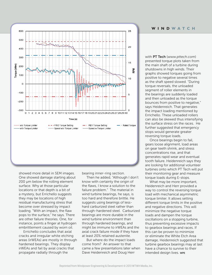
with PT Tech (www.pttech.com) presented torque plots taken from the main shaft of a turbine during shutdowns in high winds. Their graphs showed torques going from positive to negative several times as the shaft speed slowed. “During torque reversals, the unloaded segment of roller elements in the bearings are suddenly loaded and then unloaded as the torque bounces from positive to negative,” says Heidenreich. That generates the impact loading mentioned by Errichello. These unloaded rollers can also be skewed thus intensifying the surface stress on the races. He further suggested that emergency stops would generate greater reversing torque loads. Once bearings begin to fail, gears loose alignment, load areas on gear teeth shrink, and stress concentrations rise, and that generates rapid wear and eventual tooth failure. Heidenreich says they are looking for additional volunteer turbines onto which PT Tech will put their monitoring gear and measure torque loads during E-stops. What may be more important, Heidenreich and Herr provided a way to control the reversing torque load with mechanical asymmetric torque limiter. It allows setting different torque limits in the positive and negative directions. This will minimize the negative torque loads and dampen the torque oscillations on a stopping turbine, thus preventing excessive impacts to gearbox bearings and races. If this can be proven to minimize or eliminate the White Etch Area damage, Heidenreich suggested that turbine gearbox bearings may at last have a chance to survive to their intended design lives. WPE
W I N D W A T C H
Reprinted from Windpower Engineering & Development © 2013 WTWH Media, Inc.