NREL Controllable Grid Interface for Testing of Renewable ... · ... distributed energy testing and...
57
NREL is a national laboratory of the U.S. Department of Energy, Office of Energy Efficiency and Renewable Energy, operated by the Alliance for Sustainable Energy, LLC. NREL Controllable Grid Interface for Testing of Renewable Energy Technologies 3 rd International Workshop on Grid Simulator Testing Vahan Gevorgian, NREL November 5-6, 2015 FSU CAPS, Tallahassee, FL
Transcript of NREL Controllable Grid Interface for Testing of Renewable ... · ... distributed energy testing and...

NREL is a national laboratory of the U.S. Department of Energy, Office of Energy Efficiency and Renewable Energy, operated by the Alliance for Sustainable Energy, LLC.
NREL Controllable Grid Interface for Testing of Renewable Energy Technologies
3rd International Workshop on Grid Simulator Testing
Vahan Gevorgian, NREL November 5-6, 2015 FSU CAPS, Tallahassee, FL

2
Workshop report: http://www.nrel.gov/docs/fy14osti/60246.pdf Workshop website: http://www.nrel.gov/electricity/transmission/grid_simulator_workshop.html
1st Workshop at NREL – June 2013
3
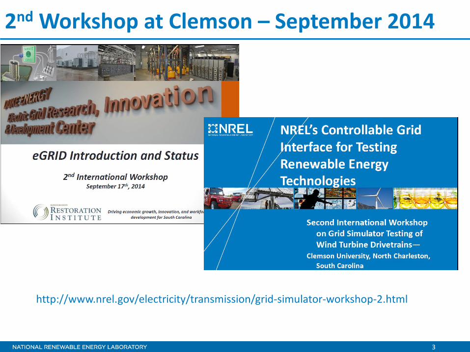
2nd Workshop at Clemson – September 2014
http://www.nrel.gov/electricity/transmission/grid-simulator-workshop-2.html
4
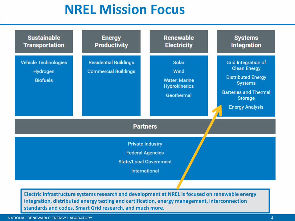
NREL Mission Focus
Electric infrastructure systems research and development at NREL is focused on renewable energy integration, distributed energy testing and certification, energy management, interconnection standards and codes, Smart Grid research, and much more.

5
U.S. Multi-MW Testing Facilities for Grid Integration Testing of Renewable Technologies
• DOE Wind Program investments in world class testing facilities
• Component, wind turbine, plant level testing • Key enabler for wind technology validation
and commercialization • Goals of DOE’s Grid Modernization, A2E and
turbine reliability programs • Specific focus on testing ancillary service
controls
Energy Systems Integration Facility (ESIF) National Wind Technology Center (NWTC)
NREL
Clemson SCE&G Energy Innovation Center, eGRID Facility
1+ MW 7 MVA
15 MW

6
NREL Golden Campus
ESIF

7
NWTC Test Site
Siemens 2.3 MW
Alstom 3 MW
GE 1.5 MW
Gamesa 2 MW
Research Turbines 2 x 650 kW
PV Array 1.1 MW
2.5 MW dynamometer
• Total of 11 MW variable renewable generation currently at NWTC test site • There are many small wind turbines (under 100 kW) installed as well • 2.5MW and 5 MW dynamometers • 7 MVA Controllable Grid Interface (CGI) for grid compliance testing • Multi-MW energy storage test pads
5 MW dynamometer, 7MVA CGI 8 MW storage
pads

8
NWTC 5 MW Dynamometer

9
NWTC 7-MVA Controllable Grid Interface

10 10
Storage Test Pads • Two pads each rated for 4 MW • Each pad can be connected to the real grid or NWTC Grid Simulator • Best for containerized storage solutions – up to 110ft ISO containers (up to 500,000 lbs) • Pre-wired, automated MV switchgear / protection installed • Fiber-optic / Ethernet

11
Power rating • 7 MVA continuous • 39 MVA short circuit capacity (for 2 sec) Possible test articles • Types 1, 2, 3 and 4 wind turbines • Capable of fault testing of world’s largest 6.15 MW Type 3
wind turbine • PV inverters, energy storage systems • Conventional generators • Combinations of technologies
Voltage control (no load THD <5%) • Balanced and un-balanced voltage fault conditions (ZVRT and
130% HVRT) – independent voltage control in each phase • Long-term symmetrical voltage variations (+/- 10%) and
voltage magnitude modulations (0-10 Hz) - SSR • Programmable impedance (strong and weak grids) • Programmable distortions (lower harmonics 3, 5, 7)
Frequency control • Fast output frequency control (+/- 3 Hz) • 50/60 Hz operation • Simulate frequency response of various power systems • RTDS / HIL capable
CGI Main Technical Characteristics
12
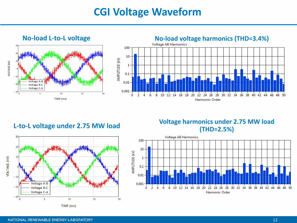
CGI Voltage Waveform
No-load L-to-L voltage No-load voltage harmonics (THD=3.4%)
0 5 10 15 2030−
20−
10−
0
10
20
30
Voltage A-BVoltage B-CVoltage C-A
TIME (ms)
VOLT
AGE (
kV)
L-to-L voltage under 2.75 MW load Voltage harmonics under 2.75 MW load (THD=2.5%)
13
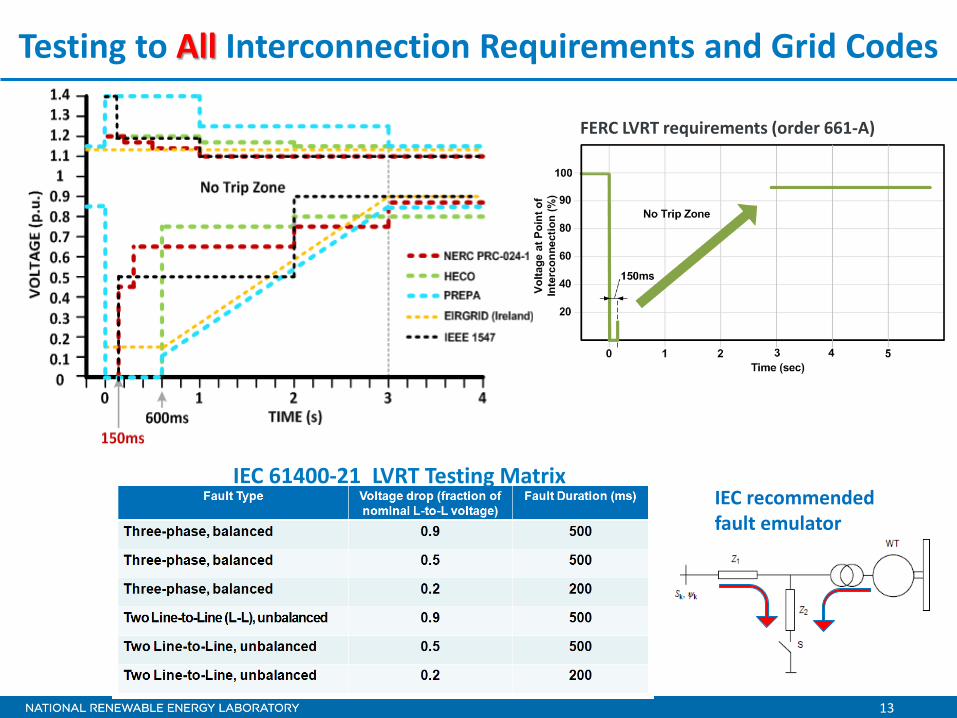
Testing to All Interconnection Requirements and Grid Codes
FERC LVRT requirements (order 661-A)
IEC 61400-21 LVRT Testing Matrix IEC recommended fault emulator

14
What can be tested using CGI? All controls that response directly to grid conditions on plant terminals*
– Inertial Response (synthetic synchronous inertia) – Fast Frequency Response (FFR) – Primary frequency response controls (governor droop-like control) – Direct frequency control (for islands or microgrids) – Black-start capability – Voltage fault ride-through (LVRT, ZVRT, HVRT – 1, 2, 3 – phase) in accordance
to any existing or future grid codes or standard – Harmonic injections – Reactive power controls (full reactive power range tests without impacting
NTWC grid) Weak and strong grid conditions
– Other advanced controls testing: Inter-area oscillation damping controls Sub-synchronous resonance (SSR) damping controls Other plant-level controls using RTDS/HIL for larger plant simulation Microgrid controls testing
*All above tests for a single technology (energy storage, wind, PV), or for combination of technologies
15
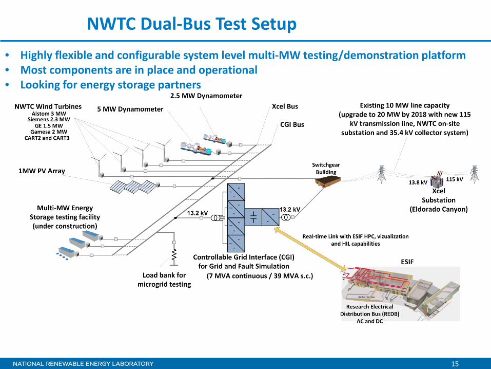
NWTC Dual-Bus Test Setup • Highly flexible and configurable system level multi-MW testing/demonstration platform • Most components are in place and operational • Looking for energy storage partners

16
Example test result: Single-phase fault emulated on MV terminals of 2.75 MW wind turbine

17
Two-Phase Fault
18
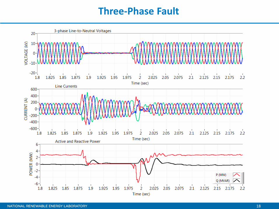
Three-Phase Fault

19
Three-Phase Fault - Slow Recovery

20
Three-Phase 130% Overvoltage
21
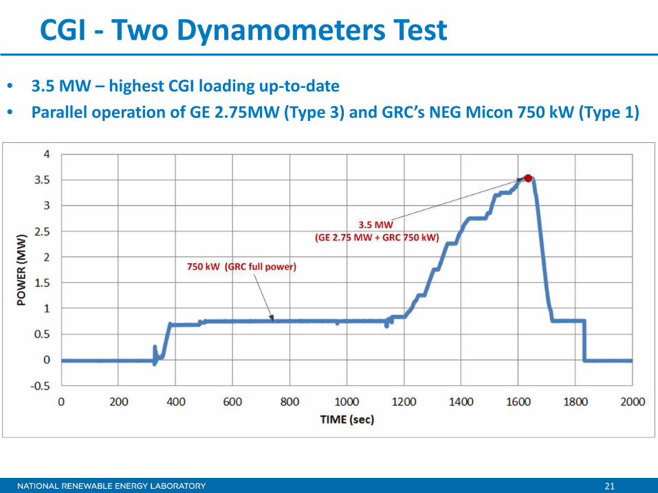
CGI - Two Dynamometers Test • 3.5 MW – highest CGI loading up-to-date • Parallel operation of GE 2.75MW (Type 3) and GRC’s NEG Micon 750 kW (Type 1)

22
Simulated Grid Multi-Technology Testing Capability

23
CGI 13.2 kV Test Bus – Collector System
CGI
13.2/3.3 kV
3.3 /13.2 kV
JB- F10
JB- F11
F9-Way4
∆
13.2 kV / 690V3MVA
750 kcmil80 m
~=
GE 2.75 MW Inverter (3 MVA)
JB- F13
750 kcmil100 m
750 kcmil100 m
Energy Storage
750 kcmil150 m
JB- TBTSTB M3-Way5
2AWG250 m
VS 4.0 2AWG200 m ∆
13.2 kV / 690V1.75 MVA
G-Box
DFIGGE 1.5 MW
Main CB
Way4 Site 4.0 Data shed
PQ System #1
CGI DAS
Way3
VS 4.1
Way3
Way2
TB – 4AWay1
TB – 4Way1
750 kcmil350 m
∆
13.2 kV / 690V3.25 MVA2AWG
275 m
VS 4.4
Way4
Way3
G-Box
DFIGAlstom 3 MW
Main CB
750 kcmil330 m
Way5
Site 4.0 Data shed
Site 4.4 Data shed
∆
13.2 kV / 690V2.6 MVA
G-Box
Siemens 2.3 MW
Main CB
∆ G-Box
DFIGGamesa 2 MW
Main CB
13.2 kV / 34.52.35 MVA
∆
34 kV /690V2.35 MVA
2AWG, 350 m
2AWG, 275 m
CART Turbines
PQ System #2
0.277 mH/km0.102 ohm/km
0.5 uF/km
0.277 mH/km0.102 ohm/km
0.5 uF/km
0.277 mH/km0.102 ohm/km
0.5 mF/km
0.277 mH/km0.102 ohm/km
0.5 uF/km
0.277 mH/km0.102 ohm/km
0.5 uF/km
0.4 mH/km0.863 ohm/km0.161 mF/km
TSTF Switch
13.2 kV / 480V ~=
24
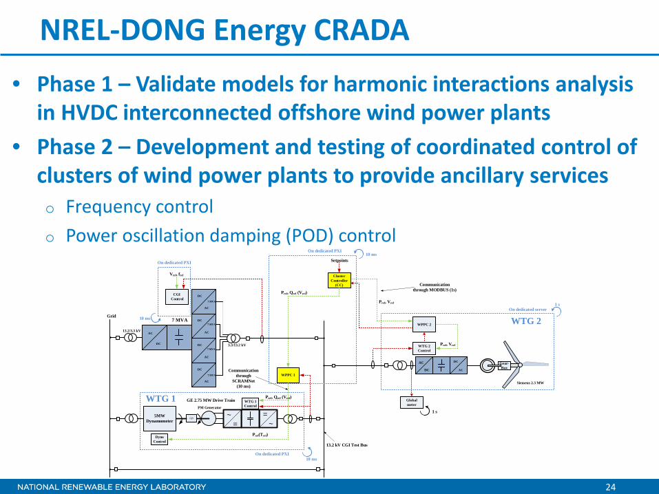
NREL-DONG Energy CRADA • Phase 1 – Validate models for harmonic interactions analysis
in HVDC interconnected offshore wind power plants • Phase 2 – Development and testing of coordinated control of
clusters of wind power plants to provide ancillary services o Frequency control o Power oscillation damping (POD) control
DC
AC
AC
DC
DC
AC
7 MVA
DC
AC
DC
AC
7 MVA
7 MVA
7 MVA
7 MVA
3.3/13.2 kV
13.2/3.3 kV
DC
AC
AC
DC
Gear-Box
~~
==
GB5MW
Dynamometer
PM Generator
GE 2.75 MW Drive Train
Siemens 2.3 MW
13.2 kV CGI Test Bus
Grid
Cluster Controller
(CC)
WTG 1 Control
CGI Control
WTG 2 Control
WPPC 1
WPPC 2
Dyno Control
Pref(Tref)
Vref, fref
Pref, Qref (Vref)
Pref, Vref
On dedicated server1 s
10 msOn dedicated PXI
On dedicated PXI10 ms
Communication through
SCRAMNet(10 ms)
On dedicated PXI
10 ms
Communication through MODBUS (1s)
Global meter
1 s
Pref, Vref
Pref, Qref (Vref)
Setpoints
WTG 1
WTG 2

25
GE 2.75 MW - 5% Frequency Droop Test
Measured droop characteristic
Frequency deadband

26
POD Control of 2.75 MW WTG
Time [s]20 30 40 50 60 70 80 90 100
PW
TG1
[kW
]
100
150
200
250
300
350
400
450
500
Measured
Model

27
2.3 MW Turbine Test Results
• Three tests conducted for three set point frequencies (0.1, 0.05 and 0.01 Hz)
• Same ±300 kW amplitude command used in all three tests

28
Model validation for WTG2

29
Results – Simulation of POD from cluster 29
100 120 140 160 180 200 220 240 260 280 300
PW
PP [p
u]
0.4
0.5
0.6
0.7
0.8
Time [s]100 120 140 160 180 200 220 240 260 280 300
Pre
f [p
u]
0.2
0.4
0.6
0.8
1P
ref1 + P
refPOD1
Pref2
WPP 1
WPP 2
Presenter
Presentation Notes
These results are only simulations (no experiment), but since the setup is open-loop with two separate control channels, it is expected that the actual system will behave as desired. The desired coordinated response is achieved. WPP 2 is slightly over-compensated. Indeed, it can be observed in the bottom plot that the needed compensation is significant.
30
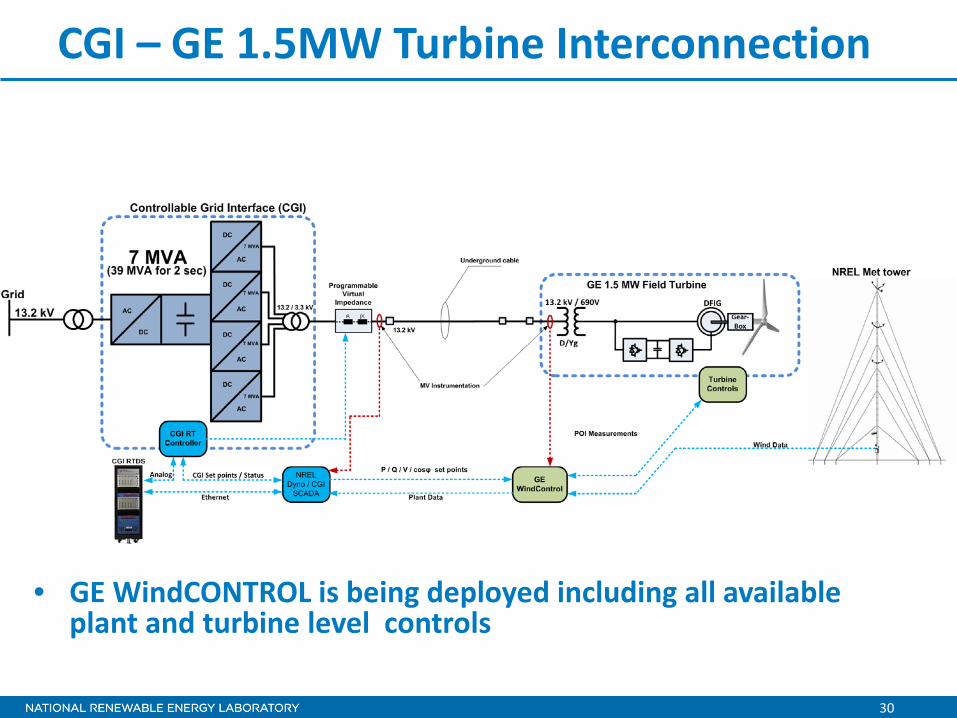
CGI – GE 1.5MW Turbine Interconnection
• GE WindCONTROL is being deployed including all available plant and turbine level controls
31
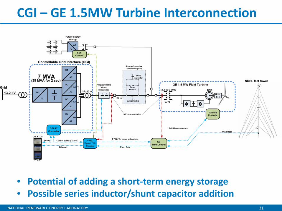
CGI – GE 1.5MW Turbine Interconnection
• Potential of adding a short-term energy storage • Possible series inductor/shunt capacitor addition

32
GE 1.5 MW field turbine operating with CGI
Voltage waveforms (690V terminals) Current waveforms (690V terminals)
Voltage THD = 1.2%

33
Voltage and current waveforms (690V terminals)
Voltage Current
Turbine harmonic filter engaged
GE 1.5 MW field turbine operating with CGI

34
NWTC/ESIF Real-time Interconnection

35
RTDS-to-RTDS Data Exchange Tests 1200 Hz sample rate received at ESIF end
1200 Hz sample rate received at CGI end
• 1200 Hz deterministic data exchange achieved
• 2000+ Hz is expected with new GTNET cards and new 10GBPS link

36
NWTC PHIL Testing Concept

37
NWTC CGI for Microgrid Testing

38
Other On-going CGI Activities • Funding received for multi-MW load bank and DC power supply
purchase (anti-islanding testing will be possible) • Project under way to test SSR damping controls on Type 3 wind
turbine using CGI • Project to test LVRT characteristics of 1.5 MW fuel cell inverter
in accordance to German grid codes at 50 Hz • CGI controls upgrade (1ms response time, <1% no load voltage
THD, scheduled Feb 2016)

39
• Cross-technology grid compliance and ancillary services testing at multi-MW level under controlled MV grid conditions
• Tool for RE industry to test for compliance with national and international electrical standards, grid codes and interconnection requirements
• Tool for advanced controls testing and validation • Helps increasing reliability and reducing integration cost of renewables generation
Value Proposition of Grid Simulator

Lab Equipment

41
1.08 MVA Grid Simulator Basic Specifications (RS270) • Voltage: 0–400 Vl-n or 400 Vdc • Frequency:
o DC or 16–819 Hz (sourcing) o DC or 16–500 Hz (sinking)
• Current: 375 A (1500 A total) • Power Flow: Bi-directional • Phase Control: Independent phase
control • PHIL Interface: Analog input
corresponding to instantaneous voltage waveform command
• Input Current THD: o Source mode: ~ 3% o Sink mode: ~ 5%
• Software Interface: o Transient list editor o Arbitrary waveform generation
• Cooling: Air-cooled
Manufacturer and Base Model Ametek RS90 (90 kVA)
Modularity Four RS270 “quads” capable of independent or parallel operation
42
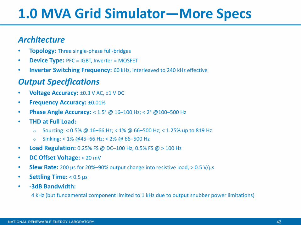
1.0 MVA Grid Simulator—More Specs
Architecture • Topology: Three single-phase full-bridges
• Device Type: PFC = IGBT, Inverter = MOSFET
• Inverter Switching Frequency: 60 kHz, interleaved to 240 kHz effective
Output Specifications • Voltage Accuracy: ±0.3 V AC, ±1 V DC
• Frequency Accuracy: ±0.01%
• Phase Angle Accuracy: < 1.5° @ 16–100 Hz; < 2° @100–500 Hz
• THD at Full Load: o Sourcing: < 0.5% @ 16–66 Hz; < 1% @ 66–500 Hz; < 1.25% up to 819 Hz o Sinking: < 1% @45–66 Hz; < 2% @ 66–500 Hz
• Load Regulation: 0.25% FS @ DC–100 Hz; 0.5% FS @ > 100 Hz
• DC Offset Voltage: < 20 mV
• Slew Rate: 200 µs for 20%–90% output change into resistive load, > 0.5 V/µs
• Settling Time: < 0.5 µs
• -3dB Bandwidth: 4 kHz (but fundamental component limited to 1 kHz due to output snubber power limitations)

43
1.5 MW PV Simulator Basic Specifications • Voltage: 25–1000 V (up to 4000 V) • Current: 250 A (up to 1500 A) • Power Flow: Supply only • PHIL Interface: Analog input
corresponding to instantaneous voltage/ current waveform command
• Bandwidth: o Voltage: 60 Hz o Current: 45 Hz
• Slew Rate: o Voltage: 4 ms for 0–63% step o Current: 8 ms for 0–63% step
• Load Transient Response: 10 ms to recover to within ± 1% of regulated output with a 50–100% or 100–50% load step
• Load Regulation: o Voltage: ±0.01% of full scale o Current: ±0.04% of full scale
• Software Interface: o PV IV curve emulation o Profile generation
• Cooling: Air-cooled
Manufacturer and Base Model Magna-Power MTD1000-250 (250 kW)
Modularity Six modules capable of independent, parallel, or series operation (up to 4000 V)

44
660 kW Battery/PV Simulator
Basic Specifications • Voltage: 264–1000 V (up to 2000 V) • Current: 2500 A (up to 5000 A) • Power Flow: Bi-directional • PHIL Interface: Digital voltage, current,
irradiance, and/or temperature commands • Load Regulation:
o Steady-state: ±0.5% o Transient: ±3%
• Load Transient Response: < 10 ms for 10–90% or 90–10% load step
• Bandwidth: o Voltage control: 180 Hz (Next Gen =
500 Hz) o Current control: 2.0 kHz (Next Gen =
2.5 kHz) • Software Interface:
o PV IV curve emulation o Battery emulation o Profile generation
• Cooling: Liquid-cooled
Manufacturer and Base Model Anderson Electric Controls AC2660P (660 kW)
Modularity Currently one module; future two modules capable of independent, parallel, or series operation

45
1.5 MVA Load Bank
Manufacturer and Base Model LoadTec OSW4c 390 kW/kVARL/kVARC RLC Load Banks
Modularity Four modules can be operated independently or in parallel
Basic Specifications • Voltage: 0–346 Vl-n/600 Vl-l • Frequency:
o L and C: 45–65 Hz o R: DC–400 Hz
• Power: o 390 kW/kVAR @ 346/600 V 3ɸ o 250 kW/kVAR @ 277/480 V 3ɸ o 47 kW/kVAR @ 120/208 V 3ɸ o 47 kW/kVAR @ 120 V 1ɸ
• Resolution o 234 W/VAR @ 346/600 V 3ɸ o 150 W/VAR @ 277/480 V 3ɸ o 28 W/VAR @ 120/208 V 3ɸ o 10 W/VAR @ 120 V 1ɸ
• Phase Configuration: o Balanced or unbalanced 3ɸ o Single-phase o Split-phase
• PHIL Interface: Digital kW/kVAR cmds • Software Interface:
o Load profile entry • Cooling: Air-cooled

46
Additional Equipment
• PV Simulators – 100 kW Ametek TerraSAS
• DC Supplies – 250 kW AeroVironment AV-900
• Load Banks – 100 kW R-L (portable) – 100 kW R (portable)
• Small Grid Simulators – 45 kW Ametek MX45 – 15 kW Elgar
• Diesel Generators – 125kVA and 80 kVA Onan/Cummins – 300kVA Caterpillar
• Hydrogen Systems – Electrolyzers: 50kW, 10kW – Storage tanks – Fuel cells
• Real-Time Digital Simulators – Opal-RT (4 racks) – RTDS (2 racks)
• LV Line Length Simulator (soon)

Questions?
Thank you !

48
Energy Systems Integration Facility (ESIF)
49
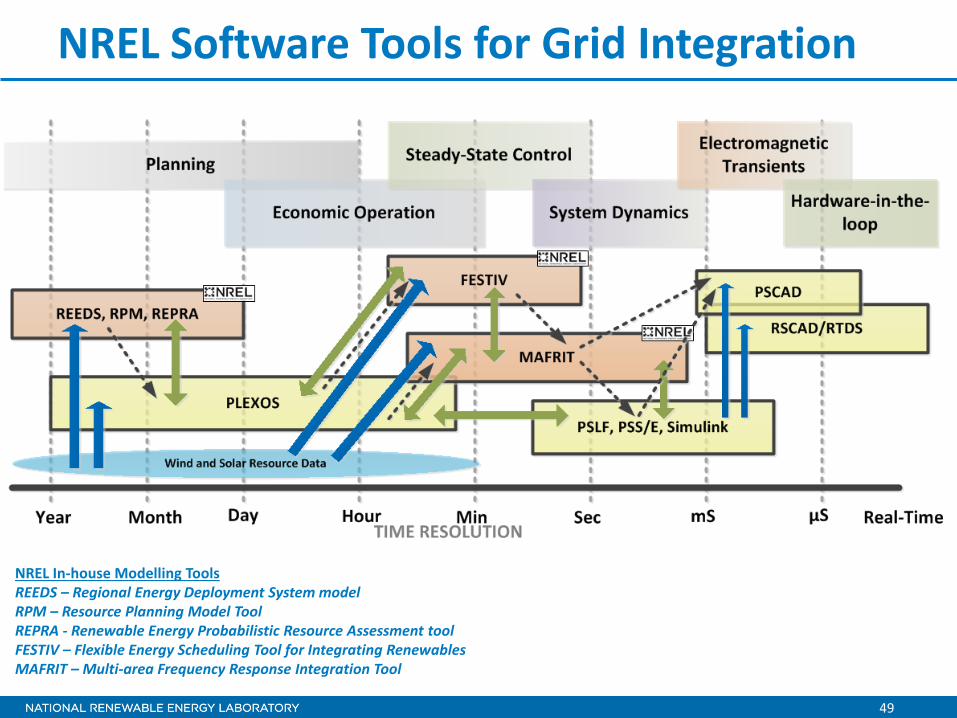
NREL Software Tools for Grid Integration
NREL In-house Modelling Tools REEDS – Regional Energy Deployment System model RPM – Resource Planning Model Tool REPRA - Renewable Energy Probabilistic Resource Assessment tool FESTIV – Flexible Energy Scheduling Tool for Integrating Renewables MAFRIT – Multi-area Frequency Response Integration Tool

50
Frequency Events in Western Interconnection
51
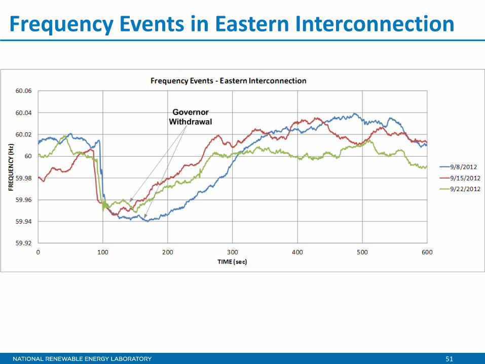
Frequency Events in Eastern Interconnection
52
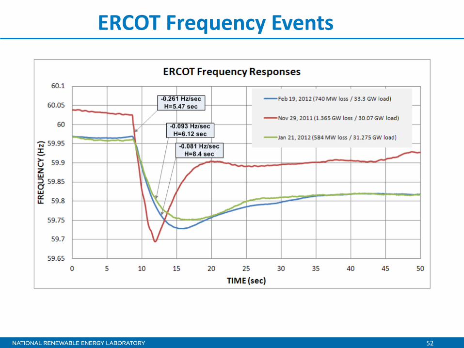
ERCOT Frequency Events

53
Frequency Response of an Island Power System

54
Single-Phase Fault - Slow Recovery

55
Single-Phase 130% Overvoltage

56
Two-Phase 130% Overvoltage

57
Three-Phase Overvoltage – Slow Recovery


![Controllable Sliding Bearings and Controllable Lubrication ... · Review Controllable Sliding Bearings and Controllable ... or evolutionary [5], but it does not change the fact that](https://static.fdocuments.in/doc/165x107/5fc50df11ca4e1756528a85b/controllable-sliding-bearings-and-controllable-lubrication-review-controllable.jpg)