
NOTE TO - University of Toronto
168
NOTE TO USERS The original manuscript received by UMI contains pages with slanted print. Pages were microfilmed as received. This reproduction is the best copy available UMI
Transcript of NOTE TO - University of Toronto
NOTE TO USERS
The original manuscript received by UMI contains pages with slanted print. Pages were microfilmed as received.
This reproduction is the best copy available
UMI


THE EFFECTS OF SURFACE MODIFYING MACROMOLECULES ON THE BLOOD COMPATIBILITY OF POLYETHERSULFONE MEMBRANES INTENDED FOR BIOMEDICAL APPLICATIONS
Jeannette Yin Chun Ho
A thesis subrnitted in conformity with the requirements for the degree of
MASTER OF APPLIED SCIENCE
Graduate Department of Chemical Engineering and Applied Chemistry University of Toronto
O Copyright by Jeannette Y .C. Ho October 1997

395 Wellington Street 395, rue Wellington Ottawa ON K I A ON4 Ottawa ON KI A ON4 Canada Canada
Your hle Votfe reférence
Our /de Notre rétérence
The author has granted a non- exclusive licence allowing the National Library of Canada to reproduce, loan, distribute or sel1 copies of this thesis in rnicrofonn, paper or electronic formats.
The author retains ownership of the copyright in this thesis. Neither the thesis nor substantial extracts fiom it may be printed or otherwise reproduced without the author's permission.
L'auteur a accordé une licence non exclusive permettant a la Bibliothèque nationale du Canada de reproduire, prêter, distribuer ou vendre des copies de cette thèse sous la forme de microfiche/film, de reproduction sur papier ou sur format électronique.
L'auteur conserve la propriété du droit d'auteur qui protège cette thése. Ni Ia thèse ni des extraits substantiels de celle-ci ne doivent être imprimés ou autrement reproduits sans son autorisation.

1 I A J 2 u 1 - l . m L 1 u u m . u u l \ m - r a b W L V X V U r n X r n .- A.=A =-a.-*.*---- - --- - A . - -a-
BLOOD COMPATIBILITY OF POLYETHERSULFONE MEMBRANES
INTENDED FOR BIOMEDICAL APPLICATIONS
Jeannette Yin Chun Ho
MASTERS OF APPLIED SCIENCE 1997
Graduate Department of Chernical Engineering and Applied Chernistry
University of Toronto
ABSTRACT
This work further investigates the use of novel surface rnodifying macromolecules (SMMs) for
use in polyethersulfone (PES) as a component of membrane materials and for consideration in
the development of blood compatible membranes in biomedical ultrafiltration applications.
Synthesized SMMs containing varying chemical compositions were characterized and blended
with PES for fabrication into flat sheet and hollow fibre membranes. The bulk thermal
transitions of PES materials were not significantly altered by the addition of 4 wt% SMMs.
Through microscopy techniques, a mode1 of the morphology of the SMM-PES membranes was
developed. It was shown that the surface energy of the modified membranes was lower due to
the migration of SMM microdomains to the air-membrane interface. The potential blood
compatibility of the PES hollow fibre membranes was investigated. Fibrinogen adsorption was
shown to be reduced on SMM modified membranes. An in vitro whole blood study using a
rocking platform apparatus and fluorescence activated flow cytometry was inconclusive as to the
potential platelet/leukocyte activating properties of hollow fibre membranes. This resulted from
inconsistencies in the donor blood, the supply of antibody used, and the effects of the surface
roughness and contamination on the membranes.

1 would like to express my gratitude to my research supervisor, Dr. Paul Santerre, for his
guidance and support throughout this thesis and the preparation of this document. 1 especially
appreciate his encouraging words and devoted tirne.
1 also want to thank those who not only welcomed me into their laboratories, but took the time to
assist me in my research and offer their knowledge. These include Mr. Frank Gibbs for DSC
studies at the Brockhouse Institute for Materials Research, McMaster University, Dr. Wilhelmy
Neumann and Mr. Dan Kwok for undenvater contact angle experiments at the Laboratory of
Applied Surface Thermodynamics, University of Toronto, Dr. Xiajia Gu for confocal microscopy
work at the Ontario Light and Laser Research Centre, University of Toronto, Dr. Takeshi
Matsuura and Dr. S. Deng for the fabrication of hollow fibre membranes at the Industrial
Membrane Research Institute, University of Ottawa, Mr. Glenn McClung and Dr. John Brash for
fibrinogen adsorption studies at the Department of Pathology, McMaster University, and ?.."S.
Elaine Chung, Dr. Cynthia Gemmell, and Dr. Michael Sefton for whole blood studies ai the
Canadian Red Cross and Department of Chemical Engineering and Applied Chemi,t;y,
University of Toronto. The expertise of others are also acknowledged; Mr. Robert Chernecky for
SEM and polarized microscopy studies at the Faculty of Dentistry, University of Toronto, Dr.
Cynthia Goh for AFM studies at the Department of Chemistry, University of Toronto, and Dr.
Rana Sodhi for XPS studies at the Centre for Biomaterials, University of Toronto. 1 also want to
thank Mr. Jonathan Albrecht for his artistic talent in assisting with the production of selected
diagrarns in this thesis and his help in the final edits of this document.
1 want to Say thank you to everyone in Room 461 who shared my life with me over the past two
years. 1 am grateful for their kindness and friendships. Special thanks to Greg Woo for lending a
hand (and a coffee) in every crisis.
This work was financially supported by the Ontario Centre for Materials Research.

1 would like to thank rny family for their support, and understanding. My father has always
s h o w me the rewards of hard work. Thanks to Warren, Kevin, Julie, and Andrew for supporting
me in al1 my decisions and offering their words of advice. Special thanks to my mother and
Catherine for listening with an open mind. Many thanks to my friends for being my crutch. A
special thank you to Mr. Jonathan Albrecht for his support and encouragement. 1 will never
forget these years.

ADSA-P
AFM
BAL
DMAC
DMF
DSC
EDTA
FAFC
FITC
FSO 1
FS02
FS03
GPC
HTB
MD1
PBS
PCL
PE
PEO
PES
PMA
PPO
PVP
SEM
SFLLRN
SMM
T,
XPS
Axisymmetric Drop Shape Analysis - Profile
atomic force microscopy
ZonylTM BA-L fluoro-alcohol (low fraction)
dimethylacetarnide
dimethylformarnide
differential scanning caIorimetry
ethylenediaarninetetraacetic acid
fluorescence activated flow cytometry
fluorescein isothiocyanate
ZonylTM FSO- 100 fluoro-alcohol (low fraction)
ZonylTM FSO- 1 00 fluoro-alcohol (intemediate fraction)
ZonylTM FSO- 100 fluoro-alcohol (high fraction)
gel permeation chromatography
HEPES-Tyrode's buffer
methylene bis-p-phenyl diisocyanate
phosphate buffered saline
polycaprolactone di01
polyethylene
polyethylene oxide
polyethersulfone
phorbal 12-myristate 1 3 -acetate
polypropylene di01
polyvinylpyrrolidone
scanning electron microscopy
thrombin peptide (ser-phenyl-leu-leu-arg-asp)
surface modifying macromolecule
glass transition temperature
X-ray photoelectron spectroscopy

ABSTRACT
ACKNOWLEDGEMENTS
LIST OF ABBREVIATIONS
TABLE OF CONTENTS
LIST OF TABLES
LIST OF FIGURES
LIST OF APPENDICES
1.0 INTRODUCTION
1.1 SYNTHETIC MATERIALS FOR BIOMEDICAL MEMBRANES
1.2 BIOCOMPATIBILITY OF BLOOD CONTACTING MEMBRANES
1.3 SURFACE MODIFICATION FOR IMPROVED BLOOD COMPATIBILITY
1.4 SURFACE MODIFYING MACROMOLECULES
1.5 RESEARCH OBJECTIVES
2.0 THEORETICAL PRINCIPLES
2.1 BASIC PRINCIPLES IN POLYMER ENGINEERING
2.1.1 Molecular Weight Averages
2.1.2 Thermal Properties of Polymers
2.1.3 Polymer Blends
2.2 POLYUETHANE CHEMISTRY
2.2.1 Isocyanate Chemistry
2.2.2 Reagents Used for Polyurethane Synthesis
2.2.3 Reaction Conditions For Polyurethane Synthesis
2.3 SURFACE CHEMISTRY AND PHENOMENA
2.3.1 Properties of Membrane Surfaces
2.3.2 Surface Thermodynamics
2.3.3 Macroscopic Approach of the Equation of State
1
. . 11
iv
v
ix
X
xii
1
1
2
3
6
7
9
9
9
10
11
12
12
14
16
17
17
17
20

L . J . I I "A J AI*". V U A CU-.-' Y J "-""'
2.3.5 Characterization of Surfaces
2.4 BIOCOMPATIBILITY OF BIOMEDICAL MEMBRANES
2.4.1 Protein Adsorption
2.4.2 Blood Component Reactions
2.4.3 Blood Compatible Membranes
3.0 EXPERIMENTAL METHODS
3.1 SYNTHESIS OF SURFACE MODIFYING MACROMOLECULES
3.1.1 Materials Used for SMM Synthesis
3.1.2 SMM Synthesis
3.2 CHARACTERIZATION OF BULK POLYMEIUC PROPERTIES
3.2.1 Elemental Analysis
3.2.2 Molecular Weight Determination by Gel Permeation Chromatography
3.2.3 Differential Scanning Calorimetry
3.3 SURFACE CHARACTENZATION OF PES MEMBRANES
3.3.1 Preparation of PES Flat Sheet Membranes
3.3.2 Characterization of PES Membrane Morphology
3.3.2.1 Polarized Microscopy
3.3.2.2 Confocal Microscopy
3.3.2.3 Atomic Force Microscopy
3.3.3 Surface Analysis by X-Ray Photoelectron Spectroscopy
3.3.4 Study of Surface Energetics by Contact Angle Studies
3.3.4.1 Apparatus for Air Contact Angle Studies
3.3.4.2 Apparatus for Underwater Contact Angle Studies
3.4 BLOOD COMPATIBILITY STUDIES OF HOLLOW FIBRE MEMBRANES
3.4.1 Fabrication of Hollow Fibre Membranes
3.4.2 Fibrinogen Adsorption Studies
3.4.3 Whole Blood Studies for Determining Platelet and Leukocyte Activation
3.4.3.1 Blood-Material Contact

- - - - ,
3.4.3.3 Ce11 Count
4.0 EXPERIMENTAL RESULTS
4.1 SYNTHESIZED SURFACE MODIFYING MACROMOLECULES
4.2 POLYMERIC BULK PROPERTIES
4.2.1 Elemental Composition of SMMs
4.2.2 Molecular Weights of Synthesized SMMs
4.2.3 Thermal Transition Properties of Bulk Polymeric Materials
4.3 SURFACE PROPERTIES OF PES MEMBRANES
4.3.1 PES Flat Sheet Membrane
4.3.2 Characterization of PES Membrane Morphology
4.3.2.1 Polarized Microscopy
4.3.2.2 Confocal Microscopy
4.3.2.3 Atomic Force Microscopy
4.3.3 Elemental Composition of Membrane Surfaces Determined by XPS
4.3.4 Contact Angle Studies
4.3.4.1 Results From Air Contact Angle Analyses
4.3.4.2 Results Frorn Undenvater Contact Angle Analyses
4.4 BLOOD COMPATIBILITY OF SMM MODIFIED PES MEMBRANES
4.4.1 Hollow Fibre Membranes
4.4.2 Adsorption of Fibrinogen ont0 PES Hollow Fibres
4.4.3 Platelet and Leukocyte Activation
5.0 DISCUSSION OF EXPERIMENTAL RESULTS
5.1 SURFACE MODIFYING MACROMOLECULES
5.1.1 Synthesis of SMMs
5.1.2 Properties of SMM Polymers
5.1.2.1 Physical Appearance
5.1.2.2 Elemental Composition

3. I .L .S lvlolecular weignt Y L
5.1.2.4 Thermal Transitions 93
5.2 SMM-PES MEMBRANE COMPOSITION AND MORPHOLOGY 93
5.3 MEMBRANE SURFACE PROPERTIES 99
5.3.1 Review o f Contact Angle Methods 99
5 -3.1.1 Air Contact Angle Method Using a Goniometer 99
5 -3.1 -2 Undenvater Contact Angle Method 1 O0
5.3.2 Surfcace Energetics of PES and SMM Modified Membranes 1 03
5.4 EFFECTS OF SMMs ON THE BLOOD COMPATIBILITY OF PES MEMBRANES 105
5.4.1 Properties of the PES Hollow Fibre Membranes 105
5 .4.2 Fibrinogen Adsorption 1 06
5.4.3 Activation of Blood Components 108
6.0 CONCLUSIONS I l l
7.0 RECOMMENDATIONS 113
8.0 REFERENCES 116
APPENDICES 126

Table 3-1 : Materials for SMM Synthesis
Table 4-1: Physical Appearances of SMMs in the Final Dry Processed Form
Table 4-2: Weight Percent Elemental Compositions of Synthesized SMMs
Table 4-3: Polystyrene Equivalent Average Molecular Weights of SMMs
Table 4-4: Glass Transition Temperatures of Synthesized SMMs
Table 4-5: Glass Transition Temperatures of PES and SMM Modified PES Membranes
Table 4-6: Sizes Of Microdomains in 4 wt% SMM Modified PES Membranes
Table 4-7: XPS Results of Elemental Composition at the Surfaces of PES and SMM
Modified PES Membranes
Table 4-8: Results of Air Contact Angle Analyses on PES Membranes
Table 4-9: Results of Underwater Contact Angle Analyses on PES Membranes
Table 4-10: Fibrinogen Adsorption Results For 4 wt% SMM Modified PES Hollow
Fibre Membranes
Table 4-1 1 : Platelet Activation on PES Hollow Fibre Membranes
Table 5-1 : Elemental Composition of FSO- 100 Fractions
Table 5-2: Possible Chemical Structures of FSO Fractions
Table 5-3: Estimates of Average Molecular Structures of FSO Fractions as
Determined by Elemental Analysis
Table 5-4: Theoretical (Based on a 3:2:2 Stoichiometry) and Experimental Compositions
of Elemental Nitrogen and Fluorine in SMMs

Figure 1-1:
Figure 2-1:
Figure 2-2:
Figure 2-3:
Figure 2-4:
Figure 2-5:
Figure 2-6:
Figure 3-1 :
Figure 3-2:
Figure 3-3:
Figure 3-4:
Figure 3-5:
Figure 4-1:
Figure 4-2:
Figure 4-3:
Figure 4-4:
Figure 4-5:
Figure 4-6:
Figure 4-7:
Figure 4-8:
Figure 4-9:
Chernical Structure of Polyethersulfone 2
Commonly Used Isocyanates for Polyurethane Synthesis 14
Commonly Used Polyols for Polyurethane Synthesis 15
Surface Energy Diagram 19
Typical Langmuir Adsorption Isotherm 27
Cascade of Reactions Leading to the Process of Coagulation 29
PIatelet Reactions involved in the Formation of Thrombus 30
Schematic of Two Step Synthesis of Surface Modifying Macromolecule 36
Reactions in the Synthesis of MDI-PPO-BAL 38
Apparatus for Air Contact Angle Studies 45
Apparatus for Undenvater Contact Angle Studies 47
Rocking Platform Apparatus for Contacting Blood with Tube Materials 53
for Low Shear Conditions
First and Second Themograms of PES-PVP Membrane 59
Microdomain Structures of 4 wt% SMMs within PES Membranes 62
Observed Through a Polarized Microscope
Confocal Microscopy Images of PES Membranes Underwater 64
Confocal Microscopy Images of 4 wt% MDI-PPO-BAL in PES Dry Membrane 65
Confocal Microscopy Images of the Dispersion of Microdomain Structures 66
in a PES Membrane Modified with 4 wt% MDI-PPO-BAL
Atomic Force Microscopy Images of PES and SMM Modified PES 68
Membrane Topography
Profile of Air Advancing Contact Angles and Contact Radii for 74
4wt% MDI-PCL-BAL in PES Flat Sheet Membrane
Profile of Air Receding Contact Angles and Contact Radii for 74
4wt% MDI-PCL-BAL in PES Flat Sheet Membrane
Surface Tension (y,,) of PES Membranes Underwater 76
Figure 4-10: SEM Images of Hollow Fibre Membranes
X

- SMM Modifications Containing BAL
Figure 4-12: Fibrinogen Adsorption Onto PES Hollow Fibre Membranes
- SMM Modifications Containing PPO and FSO
Figure 4-13: Fibrinogen Adsorption Onto PES Hollow Fibre Membranes
- SMM Modifications Containing PCL and FSO
Figure 4-14: Leukocyte Activation by the Upregulation of CD1 1 b
Figure 5-1: Illustration of Hydrogen Bonding Capabilities of PCI, Components
Figure 5-2: Schematic of a Flat Sheet SMM Modified PES Membrane
Figure 5-3: Dependence of Air Advancing Contact Angle on Contact Radii for
PES Flat Sheet Membrane
Figure 5-4: Illustration of Slip-Stick Action of Air Advancing Contact Angles on
4 wt% MDI-PPO-FS02 in PES Flat Sheet Membrane
Figure 5-5: Illustration of Slip-Stick Action of Air Receding Contact Angles on
4 wt% MDI-PPO-FS03 in PES Flat Sheet Membrane

Appendix A: Supplier Narnes of chernical Reagents
Appendix B: Distillation and Degassing Apparatus
Appendix C: Apparatus for the Synthesis of SMMs
Appendix D: Instrumentaion for GPC
Appendix E: Basic Components of an XPS Spectrometer
Appendix F: Apparatus for the Fabrication of Holtow Fibre Membranes by
a Solution Spinning Process
Appendix G: Serial Dilutions Used for Preparing 1 2 5 ~ - ~ g Solutions
Appendix H: DSC Thermograms of SMM Polymer and SMM Modified
PES-PVP Membranes
Appendix 1: TGA Thermograrns of Polymers Used in the Fabrication of Membranes
Appendix J: Confocal Images of SMM Modified Membranes
Appendix K: Statistical Analysis of Regions of Constant Contact Angles
in Undenvater Measurements
Appendix L: Experimental Data from the In Vitro Whole Blood Study
xii

1.1 SYNTHETIC MATERIALS FOR BIOMEDICAL MEMBRANES
The field of biomaterials encompasses a variety of materials, a wide range of applications, and
draws upon many disciplines. Polymers in particular, have been used extensively in biomedical
devices such as catheters, heart valves, and dialysis membranes. Many of these polymers were
originally developed for industrial applications and were then adopted as biomaterials based on
their favourable characteristics. One area in which polymers have been important is in the
fabrication of biomedical membranes for artificial kidneys in haemodialysis. At the present time,
haemodialysis is one of the most important clinical applications of blood contacting materials.
In industry, devices used for blood purification represents almost 50% of the ultrafiltration
membrane market (1 994) [Dutre et al., 19941. Earlier artificial kidneys employed cellulosic
membranes due to their tensile strength and ability to be processed into flat sheets, large tubes or
hollow fibres. In the 1970s, synthetic membranes were introduced to improve upon the
efficiency of dialysis and its biocompatibility. However, 85% of haemodialyzers still use
cellulosic membranes due to their relatively low cost [Kazuhiko, 19921.
Several designs of the artificial kidney have been introduced with membrane configurations
including flat plates and hollow fibres. Hollow fibres are currently the preferred mode for
dialysis systems due to their compact design, large surface area, and low cost. The most widely
used polymers for the membranes include polyacrylonitrile, polysulphone,
polymethylmethacrylate, polycarbonate, polyamide, and polyvinyl alcohol. A less studied
material is polyethersulfone which has more recentiy been considered due to its relative strength
and biocompatibility [Maher, 7 9951.
Polyethersulfone (PES) is a high performance thermoplastic that has been used for a number of
membrane separation processes including ultrafiltration, pervaporation, and dialysis [Cheryan,
19861. This is due in part to its excellent oxidative, thermal and hydrolytic stability. In the

--------- , - - - - - - - - - - - -- - - - - - - - - - - - - . - - , - - - - - - - - - - - - - - - - - - - - - - - - - - - - - - - - - - - - . . - - - - - - - - - - . - - - - -
of repeated sterilization techniques [Maher, 19951. The siiperior characteristics inherent of PES
materials are due to its basic chernical structure, illustrated in Figure 1-1. The sulfone unit gives
thermal stability and strength, while the ether linkage provides the chain mobility and ease of
processing [Maher, 19951. PES also dissolves in a variety of solvents which makes the material
easily processable into films or tubes by casting procedures.
Figure 1-1: Chernical Structure of Polyethersulfone
1.2 BIOCOMPATIBILITY OF BLOOD CONTACTING MEMBRANES
A major limitation of a biomaterial is that its surface is foreign to the blood and tends to promote
the destruction of blood cells, denaturation of proteins, and the formation of blood clots. These
problems are no more pronounced than in the biocompatibility of dialysis membranes which may
lead to a number of adverse immune responses, with acute and chronic impacts on the patient.
Upon contact with a foreign surface, several events may occur from blood-membrane
interactions. These include protein transformation at the membrane interface, ce11 adhesion,
aggregation, and activation, mechanical shearing, and leachiiig of materials [Cheung, 19901. The
alteration of many proteins at the tnembrane surface is probably responsible for the most severe
clinical consequences [Cheung, 19901.
The initial events of blood contact is the adsorption of proteins such as fibrinogen and albumin.
Certain proteins may undergo alterations in their structures and subsequently activate the
coagulation and complement systems. The adsorption of fibrinogen also enhances the adhesion
of cells such as platelets, erythrocytes, and leukocytes, ont0 its surface. Consequently, activated

~ U I I I ~ I C I I I I C I I I L ~ I U L ~ L I I D QIIU a b u v a L b u I ~ L L R U L ~ L G D LQII a i l i c a u LW b i l l i i b a i cvciim a u ~ i i as L U A I L ~ L ~ aiiu
allergic responses [Cheung, 19901. The pathways and mechanisms of activation are complex and
are further described in Section 2.4.
There have been many methods introduced for minimizing the interactions of blood at the
biomaterial surface. For example, anticoagulants, the most popular being heparin, are used in
dose administration or have been attached ont0 the surface of dialysis membranes to reduce
clotting on rnedical devices. However, anticoagulation has been associated with several side-
effects including a risk of haemorrhaging [Amiji, 19941. Research has now focused on more
biocompatible membranes with most of the efforts concentrated on modifjing the surfaces of
existing materials.
1.3 SURFACE MODIFICATION FOR IMPROVED BLOOD COMPATIBILITY
Many researchers have investigated different methods of modi@ing currently used materials for
improving biocompatibility. The goal is to take advantage of the mechanical properties of
synthetic polymers but improve upon the surface characteristics which will render them blood
compatible. The most common methods introduced for modifying surfaces of biomaterials are
briefly described in this section.
One method of surface modification for improving the biocompatiblity of dialysis membranes is
to ionically bond biological species ont0 the surface of the polymer in order to simulate the
surface of a biological system [Piskin, 19921. The most studied of the bioactive species has been
lieparin, a natural anticoagulant responsible for the fluidity of blood. However, for long term
applications, heparinization may fail because the heparin will eventually be depleted through
desorption processes [Silver et al., 19921.
The surface properties of membranes can also be altered by the addition of functional groups.
There 11as been numerous studies on halogenation [Mohr et al., 1991; Clarotti et al., 19921,
LU uunyiaiuii 11 i ~ i u i a y C L ai., i YYLJ ana suironauon Llviclvriirin, 1 YUYJ or polymers. bxamples
include the grafting of 2-methacryloyloxyetl~yI phosphorylcholine [Kazuhiko, 19921 and
poly(ethy1ene glycol) [Amiji, 19941 ont0 cellulose membrane surfaces. Such grafting techniques
can be achieved by either a coupling reaction of existing polymer chains or plasma deposition of
monomers ont0 the surface of the porous material [Wu et al., 921. The latter technique has also
been used to deposit thin fluorocarbon coatings from an argon plasma containing
perfluorohexane to give a smooth hydrophobic surface membrane [Clarotti et al., 19921. Several
studies have also modified membrane surfaces to prevent protein adsorption by adsorbing block
copolymers ont0 the surface [Schroen et al., 1993; Matsuda et al., 19943. Although surface
coating and grafting methods are effective in modifiing the surface properties of polymers, the
techniques may require special equipment and therefore may be costly.
Surfaces can also be modified by blending polymer additives into the base material. This method
has been less popular for biomedical applications because of the possibility for leaching of the
additives, and concern of their cytotoxicity [Ikada, 19941. However, studies over the past several
years have suggested that this may be a promising method for improving the biocompatibility of
biomaterials. In these techniques, small amounts of surface modifj4ng additives are blended with
a base polymer which has the desired physiological properties for the biomaterial. Surface
modification is effected by the migration of the additives to the surface of the base polymer
during fabrication of the device. Therefore, the final surface characteristics reflect those of the
additives concentrated at the surface, leaving the bulk of the material unchanged. The additives
are relatively high molecular weight copolymers which are compatible with the base polymer and
should be amphiphiIic, having both polar and nonpolar segments [Ward, 19891. The
reorientation of these blocks at the surface minirnizes the interfacial energy between the blood
and polyiner surface and therefore improves its biocompatibility.
Studies on surface modi@ing additives for polymer surfaces have included the work of Ward
119891 who synthesized arnphipathic multipolymers as surface-modibing additives (SMA) for
use in biomedical polymers to reduce thrombogenicity. It was found that the approach to
equilibrium of the SMAs at the surface was slow and hence their group further developed

puiyrricrs wiiri aurlace-lvioairying c n a uroupsLWA (sivrc) [wnite et al., 1YYbJ. Biomedical
devices would then be synthesized by this modified polymer. The latter technique is different
from blending a polymer additive with a base polymer since here, each base polymer molecule is
synthesized by incorporating the SMEs. Other studies have also shown reduced protein
adsorption ont0 poly(ether urethaneurea) films modified with methacrylate based surface
additives. These include Brundstedt et al. [1993] through the addition of amphiphilic or
hydrophobie polyacrylate or methacrylate, and Freij-Larsson et al. [1993] with a
polymethacrylate additive identified as poIy(diisopropylaminoethyI methacrylate-co-decyl
methacrylate). Another exarnple is Kasemwa et al. [1993] who blended fluorine-containing
block copolymers, composed of methyl methacrylate, and heptadecafluorodecyl acrylate, with an
epoxy resin to improve water repellency.
The haecompatibility of fluorinated materials has been widely investigated. It has been
suggested that commercial fluoropolymers have a low surface tension and as a result adsorb Iess
protein [Kaku et al., 1994; Clarotti et al., 92; Garbassi et al., 19943. However, most commercial
fluoropoIymers are difficult to process and due to their limited solubility in common solvents, are
not suitable for some biomedical devices, such as dialysis membranes. Therefore, surface
modification techniques offer many solutions. Surface fluorination c m create a surface with
blood compatibility and chernical stability, without affecting the physiological properties of the
base polymer. This was s h o w for polyetherurethanes coated with a surface of a fluorinated
block copolymer [Kaku et al., 19941 and polyurethane catheters deposited with a fluorinated film
[Pizzoferrato et al., 19951. In copolyrners, fluorinated segments are usually enriched at the
surface. For this reason, there have been studies to synthesize polyurethanes with fluorinated
chah extenders and soft segments [Edelman, 1990; Yoon et al., 19901. As well as
biocompatibility, surface fluorination has been shown to improve the permselectivity of some
polymeric membranes including polysulfone hollow fibres [Mohr et al., 19911. There are
obvious advantages in the use of surface modifying additives and surface fluorination. This is
thc basis for the development of surface inodifj4ng macromolecules.

Surface modi@ing macromolecules (SMMs) are oligomeric fluoropolymers synthesized by
polyurethane chemistry and tailored with fluorinated endgroups [Tang et al., 1996; Pham et al.,
1997 (l)]. When added to a base polymer such as polyethersulfone, it has been shown that low
molecular weight SMMs will migrate to the surface due to their immiscibility with the base
polymer, and the fluorine endgroups will orient towards the air-polymer interface [Tang et al.,
1996; Pham et al., f 997 (2)]. This reduces the surface energy of the cast base polymer, achieving
surface energies close to that of TeflonB [Tang et al., 19961. Because only a small amount of
SMMs (not more than 4 weight percent) is added, the bulk properties of the base polymer remain
relatively unchanged [Tang et al., 1996; Pham et al., 1997 (2)]. Currently, several formulations
of SMMs have been synthesized with varying reactant ratios, each characteristically different.
The bulk properties of the SMM polymers have been characterized, including molecular weights,
elemental analysis, and thermal transitions, and the SMMs have been blended with base
polyrners of polyurethanes [Tang, 1995; Weiler, 19973 and polyethersulfone [Pham, 19951.
SMMs have been tested for use in several industrial membrane applications such as ultrafiltration
and pervaporation, providing membranes with low surface energies, chernical resistance, and
improved surface Iubrication [Harnza et al., 1996; Fang et al., 1994; Pham, 19961. In
ultrafiltration applications, polyethersulfone membranes modified with SMMs also showed
reduced fouling and increased flux for treating oil/water emulsions [Hamza et al., 19961. Tang et
al. 11996, 1997 (l)] have suggested the use of these additives for surface modification of
biomaterials such as segmented polyurethanes. Such modifications can improve the blood
cornpatibility of polyurethanes by reducing protein adsorption [Tang et al., 1997 (2)] and
minimizing white blood ce11 activation [jahangir, 19961. As well, the presence of SMMs at the
surface of polyurethanes reduced the hydrolysis of the material by lysosomal enzymes, thereby
showing an increase in overall biostability [Tang et al., 1997 (1); Tang et al., 1997 (2)]. The
degree to wliicl-i SMMs improve these aspects of biocompatibility depends on the formulations
and reagents used in their synthesis.

From the above discussion, there is a clear need for improving the blood compatibility of
biomedical membranes for applications such as haemodialysis. Recent work has focused on the
surface properties of materials that are in direct contact with blood. Surface modification c m
improve upon the biocompatibility of a material by altering its surface properties without
significantly affecting the strength and dexterity of the material. While conventional methods of
surface modification require a second processing step that may translate into added equiprnent
costs, surface modification with SMMs has been proven to be a simpler method.
It is hypothesized that the surface properties of dialysis membranes can be tailored by the
addition of SMMs so as to improve the blood compatibility of the membrane without affecting
its bulk properties. The addition of SMMs will lower the surface tension of the base material
producing relatively more hydrophobic surfaces through the migration and concentration of
SMMs at the surface. By lowering the surface tension, this rnethod has the potential for
improving the blood compatibility of a material by reducing protein adsorption and platelet
activation. Because only a small percentage of SMMs is used, the surface properties will be
altered without significantly changing the bulk properties. The surface properties will be
expected to depend on the chemical nature of the SMMs used, and SMMs with varying chemical
compositions should exhibit varying degrees of miscibility in the base polymer.
The scope of this thesis was to study the surface characteristics (physical and biological) of SMM
rnodified PES membranes intended for possible biomedical ultrafiltration and microfiltration
applications such as dialysis. The SMMs were synthesized to study the effect of varying
chemical compositions on both the miscibility of the additives in the base polymer and the
surface properties induced. The synthesized SMMs were characterized for their bulk properties,
and the morphology and surface properties of the SMM modified membranes were assessed.
The surfaces of the membranes were characterized by air and underwater contact angle studies,
X-ray photoelectron spectroscopy and various microscopy techniques. By these methods, a
mode1 of the dispersion of SMMs in PES membranes can be developed. Aspects of blood

~ u l I l p U ~ ~ ~ ~ ~ ~ ~ J LUI IIIVUIII~U I LLI L I W ~ ~ U V V IIUI C, IIILIIIUI a 1 ~ 3 WLI L a 1 w I u v c a u g a i c u W ~ L N 1 C ~ ~ C L L LU
fibrinogen adsorption, platelet activation, and leukocyte activation. From these results, the
effects of surface morphology and surface properties induced by SMMs of differing chernical
compositions may be correlated to their effects on the blood compatibility of PES membranes.

2.1 BASIC PRINCIPLES IN POLYMER ENGINEERING
2.1.1 Molecular Weight Averages
A polymer is a molecule consisting of many repeat units of a monomer and as a result has a high
molecular weight which rnay Vary depending on the number of repeat units. The general
influence of molecular weight on a polymer's mechanical properties is such that the properties
increase with increasing molecular weight, and levels off at a maximum that varies from polymer
to polymer [Speckhard et al., 19861. Therefore low mechanical strength is often due to low
molecular weights. However, the higher the molecular weight the more difficult it may be to
process the polymer [Lelah et al., 19861.
Since the number of repeat units can Vary between molecules of the same polymer, the polymer
molecular weight is an average of the total number of molecular weights and its definition
depends on the weighting factor. The number average rnolecular weight is based on the number
of moles in the sample and is given by:
where xi is the mole fraction of species i (Le. the number of polymer chains of a specific
inolecular weight), and Mi is the molecular weight of species i. A second measure of molecular
weight is the weight average molecular weight which reflects the weight of the different fractions
within the polymer and is given by:

- -
molecular weight species. The ratio of MW to Mn is the polydispersity of the polymer which
defines the breadth of the molecular weight distribution. A narrow molecular weight distribution
comesponds to a polydispersity close to 1. Typical values for commercial polymers range from
1.5 to 50 [Lelah et al., 19861. The shape of the molecular weight distribution can have a
significant effect on the polymer's physical characteristics.
2.1.2 Thermal Properties of Polymers
The thermal properties of polyrners and polymer blends are important considerations for
industrial applications. One important property is the glass transition temperature, Tg , which is
the temperature, or range of temperatures, below which the polymer is in a glassy state and above
which it is rubbery. It is associated with the abrupt cessation of polymer backbone rotations
resulting from a decrease in temperature [Lelah et al., 19861 and varies with each polymer and
polymer mixture. This parameter is distinguished from the melting temperature, Tm , which is
the temperature above which the solid polymer becomes a liquid phase. The glass transition
temperature depends on five factors, the free volume of the polymer, the attractive forces
between the molecules, the interna1 mobility of the chains, the stiffness of the chains, and the
chain length [Rosen, 19931. In segmented polymers, such as polyurethanes, the Tg of the
polymer may be used as a measure of microphase separation [Wang et al., 19831. In copolymers,
it usually varies monotonically with composition between those of the homopolymers [Rosen,
19931. These transition temperatwes can be determined by observing the changes in
thermodynamic properties of the polymer, for example the specific volume or refractive index,
with changes in temperature. A conventional method of characterization is differential scanning
calorimetry (DSC) where the thermal property monitored is the change in enthalpy. The method
of DSC analysis is detailed in Section 3.2.3.

The processability and final properties of polymer blends, such as the SMM modified PES
membranes studied in this work, will depend on the amount of SMM added in PES and the
miscibility of the two polymers in the casting solution. This may also determine the phase
separation of the two during membrane formation as the solvent evaporates. Phase separation is
a phenomena which has been observed in additive modified polymer blends in the formation of
films [Brundstedt et al., 19931 due to the therrnodynamic incompatibility of the polymer blend,
causing demixing. These blends wili have phase domains which consist of regions of
concentrated pure components.
An immiscible blend will affect the homogeneity of a cast membrane and thus its surface
properties since surface roughness plays an important role in surface energetics. In previous
studies, it was observed that phase separation was achieved with 1 wt% SMM in the casting
solution and that an increased arnount of SMM added may cause perturbations in the surface
morphology of the PES substrate [Pham et al., 1997 (2)] . The surface composition of SMM in
base polymer can also vary with the choice of casting solvent, the procedures used for
precipitation and the external drying environment [Bergbreiter, 19%; Sharma et al., 19841. The
miscibility of polymer blends is often determined by the rneasure of a single Tg as a function of
composition [Couchman et al., 1978; Aubin et al., 19881. In general, for a binary polymer blend,
the Tg is observed to increase approximately monotonically with increasing composition of the
component with the highest Tg [Aubin et al., 19881.

The chemistry used for the synthesis of SMMs in this thesis is based on polyurethane chemistry.
Polyurethanes are linear alternating block copolymers consisting of long flexible soft segments
and highly polar and stiff hard segments. The synthesis can be performed by a one step or two
step process. The reactants are mixed simultaneously in the one step process with a suitable
catalyst and the result is a random copolymer polyurethane. The two step process produces
random or block copolyrners by the initial reaction of a diisocyanate and a polyol, and then a
coupling reaction effected by adding a di01 or diamine. The mechanism of the reaction follows
that of step growth polymerization in which the reaction is dependent on the end functional
groups of both molecules, and is independent of the rest of the molecule chain if there are more
than five or six repeat units [Rosen, 19931. Synthesis of polyurethanes are either performed as
bulk or solution polymerizations.
2.2.1 Isocyanate Chemistry
The isocyanate group in the diisocyanate reagent consists of three resonance structures:
The presence of these structures allows for different side reactions with themselves and chemical
groups with active hydrogens. The nucleophilic attack of urethane and urea linkages ont0
isocyanates is also a possible sequence of reactions, producing allophanates and biurets [Lelah et
al., 19861. These products can result in chemical crosslinking of the polyrner chains. Other side
reactions include the formation of dimers and trimers from aromatic isocyanates. Aromatic
isocyanates easily dimerize at low temperatures, especially in the presence of acidic or basic
catalysts [Gogolewski, 19891. Both the formation of dimers and trimers will cause an imbalance
in the reactant ratios and therefore, branching and crosslinking can occur.

'1 he synthesis 01 polyuretnanes 1s aepenaent on rne resonance siruuurcs o r LM I ~ U L ~ L U I ~ ~ L G g i u u p .
A prepolymer of molecular weight between 1,000 and 5,000 is formed by an addition reaction
between an isocyanate group and a hydroxyl group of an oligomeric diol, as shown in Equation
(2-4) [Lelah et al., 19861.
The bonding between the isocyanate and the hydroxyl group generates a urethane linkage. To
produce long chain polyurethanes with high molecular weights, the prepolymer can be chain
extended with either a low molecular weight diol, resulting in a polyurethane, or a low molecular
weight diamine, resulting in the formation of a polyurethane-urea. As well, low molecular
weight polyurethanes with varying characteristics can be produced by endcapping the products of
the prepolymer reaction in place of the chain extension step.
While water molecules may be desired, as in the production of polyurethane foarns, in most cases
they are considered a contaminant. Water molecules react with the isocyanate groups in a similar
manner as hydroxyl groups, producing carbon dioxide and amines. The amines then react rapidly
with additional isocyanates to form urea linkages [Lelah et al., 19861, written as:
Many other impurities can also be a source of active hydrogens, including monofunctional
alcohols, amines and carboxylic acids. The reactions of the impurities will cause chain
temination and unbalance the reaction by using up diisocyanate. The end result is low molecular
weight polyiners. Therefore, it is crucial that high purity reagents be used in the synthesis of
linear polyurethanes.

2.2.2 Keagents Used tor voiyuretnane synrnesis
There are many diisocyanates used for the synthesis of polyurethanes, including toluene
diisocyanate (TDI), 4,4-diphenylmethane diisocyanate (MDI), hexamethylene diisocyanate (HDI)
and methylene bis@-cycIohexy1 isocyanate) (H12MDI) [Lelah et al., 19861. The chernical
structures of these diisocyanates are illustrated in Figure 2-1. The most commonly used
isocyanates are MD1 and TDI. The use of MD1 yields a rigid hard segment which may crystallize
with other hard segments to provide strength to the polyrner [Hergenrother et al., 19931. This is
not seen in al1 polyurethanes. For example, polymers synthesized with H12MDI do not produce
crystallized domains since the isocyanate exists in various conformational States which do not
allow the hard segments to pack appropriately. However, these isocyanates have been found to
produce polyurethanes with comparable strength to those with MD1 [Hergenrother et al., 19931.
Figure 2-1: Commonly Used Isocyanates for Polyurethane Synthesis
NCO CH3\ ,
NCO
2,4 toluene diisocyanate (2,4 TDI) 2,6 toluene diisocyanate (2,6 TDI)
methylene bis(p-phenyldiisocyanate) (MDI)
OCNHzC -(CH2)4-CH2NC0
1,6 hexane diisocyanate (HDI)

- A - - - -
chemical structure of the polyol soft segment. The polyols are generally low molecular weight
polyesters, polyethers, hydrocarbon polymers or polydimethylsiloxanes, al1 containing hydroxyl
or amine end groups. Some commonly used soft segment reagents are shown in Figure 2-2.
Polyester based polyurethanes yield good material properties but are unstable towards hydrolytic
cleavage at the ester linkage [Lelah et al., 19861. Polyethylene oxide based polymers are
hydrophilic and have poor water resistance, while polypropylene oxide based polymer are very
sofl [Lelah et al., 19861. The polyether which has shown the best physical properties is
polytetramethylene (PTMO). It produces polymers with good mechanical strength, relatively
good hydrolytic stability, and is water resistant [Lelah et al., 19861.
Figure 2-2: Commonly Used Poiyols for Polyurethane Synthesis
polyethyleneoxide (PEO) polypropylene oxide (PPO)
polytetramethylene oxide (PTMO) polycaprolactone di01 (PCL)
Specific characteristics can be introduced into the polyurethane by endcapping the prepolymer
reaction with oligomers containing certain functional groups. The chemical group of interest in
this study is fluorine and the result is an oligomeric fluoro-polyurethane polyrner. The fluorine
"tails" are introduced by reacting a fluorinated surfactant with the urethane prepolymer. The
fluoro-intermediates used in this study are manufactured by DuPont Chernicals and sold under
the registered trademark of ZonylTM. These compounds can be anionic, cationic, nonionic and
amphoteric, and are soluble in many common solvents. They can provide low surface tensions at

- - - .
material is the fluorocarbon chain, F(CF2CF2); in the molecule. The fluoro-intermediates are
effective at lowering the surface tension, while providing excellent chemical and thermal
stability. It is estimated that surfaces made with ZonylTM can achieve a critical surface tension
three times lower than that of Teflona [Dupont].
2.2.3 Reaction Conditions For Polyurethane Synthesis
The conditions of the polymerization system will influence the molecular weight, composition
distribution, and morphology of the resulting polyurethane [Speckhard et al., 19861. For
example, the molar ratios of the reactants can vary the sequence length distribution of the hard
segments and the molecular weight of the polymer [Peebles, 19741. In solution polymerization,
the solvent serves as a nonreactive medium for the reactants and resulting product. Solvents with
active hydrogens may induce undesired side reactions and are therefore not used. The most
commonly used solvents for polyurethane synthesis are dimethylsulfoxide, N-methylpyrrolidone,
dimethylformamide, N,N-dimetliylacetarnide and tetrahydrofuran [Gogolewski, 19891. The
formation of polyurethanes is an exothermic process [Gogolewski, 19891. However, in order to
achieve polyurethanes with high molecular weights, thermal energy is applied in the forrn of
heat. The temperature will depend on the reactants used and the desired properties of the final
polymer. In previous studies describing the synthesis of SMMs, it was found that the reaction
temperature, solvent volume, reactant mole ratio, reactant concentration, and stir rate were
important in determining the size and distribution of the SMM synthesized [Tang, 1995; Pham,
19951. Because of this, these variables were held constant throughout this study.

2.3.1 Properties of Membrane Surfaces
The surface of any material is inherently different from that of the bulk material and is an
important aspect in the study of biocompatibility and biomedical membranes. Wettability,
surface charge, chernical and physical heterogeneity, surface energy, and surface dynamics are
considered important properties of biomaterial surfaces [Piskin, 19921. Biocompatibility,
particularly thrombogenicity, is affected by these surface properties which will subsequently
determine its interactions with blood components. The mechanisms for adsorption of proteins to
non wettable surfaces are relatively well understood and in agreement between different
researchers. The minimum interfacial free energy hypothesis states that if the polymer-water
interface has a low interfacial free energy, then protein adsorption should be low and reversible
[Andrade et al., 1979 (2) ] . Generally, surfaces will try to rninimize their interfacial energy,
Ieading to different surface atomic structures. This is the driving force which causes the
migration of low energy surface additives, such as SMMs, to the air-polymer interface, thereby
lowering the interfacial energy.
2.3.2 Surface Thermodynamics
There are three governing therrnodynarnic expressions used to describe the energy system of a
surface. The system can be defined either by an energy balance (E), (equation 2-6), or by the
Gibbs (G) and Helmholtz (H) free energy expressions, (equation 2-7) and (equation 2-8)
respectively [Morra, 1 9901 :
dE = TdS - PdV + ydA + CpdN
dG = - SdT + VdP + ydA + CpdN
dF = - SdT - PdV + ydA + CpdN

v v ~ ~ u i u 1 8 5 uiu r u ~ i i y u r u r u i v , u A U SA*- w i i ~ . i v y J , . LW +.a- . -.....A.- ? ' *" "" r * - - - - * - y 1 '- ""
interfacial tension, p is the chemical potential, N is the normality, and A is the area of the
interface. The Helmholtz free energy is used to describe the system of contact angles because the
condition of constant T, V, and N c m be easily achieved.
The purpose of contact angle measurements is to determine the equilibrium condition at a three
phase boundary, the three phases being that of solid-liquid-vapour, or solid-liquid-liquid. For
instance, a liquid drop on a solid surface will change its shape to reach equilibrium. By
performing a thermodynamic analysis on the Helmholtz free energy expression, we c m rewrite
equation (2-8) in the form:
where 8 is the angle between the solid-liquid interface and the liquid-vapour interface, and y is
the surface tension of the corresponding interface. At thermodynarnic equilibrium, dF/dA = O
and the equilibrium is expressed by the Young Equation [Morra, 19901:
Y,$, - Y,, = Ylv 0
The Young equation has never been proven experimentally and there is much controversy on the
validity of this equation and when it applies. The reason for this is because equation (2- 10) is
described for ideal surfaces at equilibrium. However, there are many factors which c m affect the
equilibrium contact angle. One problem is the effect of spreading pressure for small contact
angles. Some argue that this can be ignored for angles greater than IO0, while otliers insist
otherwise [Morra, 19901. Another factor, not accounted for by the Young equation, is the drop
size effect as related to line tension. A 1-D analog to surface tension, its effect is to minimize the
circumference of the drop meumann et al., 19963. Drops of different sizes on the same surface
should therefore have different contact angles. This effect may be insignificant when compared
to effects due to surface chernical or morphological heterogeneity. As well, the liquid must not

---- - r - -d -
be effected by numerous factors which include thermodynamic effects such as chernical
heterogeneity and surface roughness. Time dependent effects such as swelling, penetration, and
surface mobility can also cause deviations from ideality.
Thermodynamic effects such as surface heterogeneity and roughness create free energy barriers
on the surface as illustrated in Figure 2-3 [Andrade et al., 1979; Morra, 1990; Neumann, 19741.
As a result, the system c m equilibrate in one of many free energy local minima (or metastable
states of equilibrium) giving rise to contact angIe hysteresis. The largest contact angle is termed
the advancing contact angle, and the srnallest is the receding contact angle. In general, hysteresis
is negligible for a roughness lower than 0.5 - 0.1 Pm, or heterogeneity phases smaller than 0.1
pm [Morra, 19901.
Figure 2-3: Surface Energy Diagram peumann et al., 19961
0 (degrees)

liquid system orients toward a more stable state. These effects include penetration, swelling, and
polymer mobility. Water has a tendency to penetrate and saturate intermolecular pores of some
material surfaces, and the swelling of gels have been observed in a number of studies [Morra,
1990; Holly et al., 19751. The sarne holds not just for hydrogels but for rigid polymers as well.
The driving force for surface reorientation is the thermodynamic requirement to minimize the
surface tension so that low energy groups are exposed to the polymer-liquid interface while the
higher energy polar groups are reoriented towards the bulk. Andrade et al. [1979] obtained
results which showed that hydrophilic components dominate the polymer-water interfacial
properties, even at low concentrations. Therefore it is evident that the characterization of
polymer surface properties is dependent on the working environment.
2.3.3 Macroscopic Approach of the Equation of State
The purpose of measuring contact angles is to obtain the surface tension associated with a
material surface. The determination of the solid surface tension has led to some controversy and
the debates have centred around the meaning of surface tension components. Several
investigators have introduced differing rnodels to describe the surface tension of a two phase
system. In this study, surface tension values are determined fiom contact angle analysis
according to the macroscopic approach of the equation of state. Other models are briefly
discussed in a review by Morra [1990].
A balance between surface tension and external forces is given by the classical theory of
capillarity Ir\reumann, 19741. Minimizing the overall free energy of the system gives the Laplace
equation of capillarity (equation 2-1 1) which describes the shape of the water droplet, and the
Young equation (equation 2-1 2) which provides a relationship between the contact angle and the
surface tension.

where Ri and R2 are the principal radii of curvature at a point
Ap is the density difference between the liquid and vapour phases
g is the acceleration due to gravity
z is the ordinate of a point at the liquid surface
c is a constant
AP is the capillary pressure
The details of the development of the theory of capillarity and the equations are given elsewhere
Ir\leurnann, 19741. Whereas the Young equation relates the equilibrium contact angle to the
surface tensions for smooth, homogeneous, isotropic, nondeformable ideal surfaces, the Laplace
equation of capillarity is valid for the range of contact angles inherent in non-ideal surfaces. This
is because the equation describes the shape of the liquid vapour phase and is not a consequence
of the character of the solid surface.
In the Young equation, only y,, and 8, (the equilibriurn contact angle) are rneasurable. In order to
calculate ysv and y,! , the Young equation has to be combined with an equation of state relation in
the form:
Ysi = f ( YS, , YIV ) (2- 13)
We can consider the free energy of adhesion of a molecule per unit area to be:
WSI = Yiv + Ysv - Ysi (2- 14)
where WsI is the reversible work of adhesion. From this, mathematical analysis yields the
equation of state:

The formulation of the equation of state is given elsewhere [Neumann et al., 19961. Combining
this with Young's equation (2-12) then gives:
where 8 is the Young contact angle. Equation 2-16 has been applied to experimental data and a
value for p was found to be 0.0001247 (rn2/m~)* meumann et al., 19961. For the purpose of
calculations, equation (2-1 6) may be rearranged in the form:
If we let
and
The equation of state becomes
Therefore, mathematical manipulation will involve solving for the roots x of equation (2-20) by a
numerical methods analysis and relating this to y,, in equation (2-1 8) [Neumann et al., 19961.

surface tension of other materials.
2.3.4 Polymer Surface Dynamics
Polymers are generally thought of as rigid and relatively immobile materials. However, in
changing environments, polymers have been shown to respond by re-equilibrating its surface
composition. As a result, the surface properties of these materials are dependent on their
surrounding environment. The most drarnatic example is in an aqueous environment where the
interaction of the polymer with the water provides a strong driving force for surface components
to reorient in order to reduce interfacial tension. This is an important consideration for
biomaterials since the environment for fabrication may be very different from that for its
intended use.
In an aqueous environment, the polarity of the water molecules creates an interfacial free energy
driving force for the migration of polar blocks, segments, or side chains towards the liquid
interface, in order to reduce the surface free energy. This phenornena has been demonstrated in
nurnerous studies. For example, polyurethane surfaces have been shown to undergo
rearrangements when the environment was changed from air to water. The polar component was
observed to increase in time which was due to the increase of the more polar hard segment at the
surface [Herng et al., 19901. Another example is the polymer poly(hydroxyethylmethary1ate)
(pHEMA) which orients the hydrophobic methyl groups at the polymer-air interface and the
hydrophilic hydroxyl groups at the polymer-water interface [Garbassi et al., 19941.
The equilibration of polymer surface components have been found to be temperature and time
dependent [Andrade, 1988; Jhon et al., 19881. It may also depend on the properties of the
interfacing medium which provides the thermodynamic drive for reorientation. The nature of
polymer rearrangement is dependent on the chernical and morphological composition of the
polymer to provide sufficient mobility. This mobility can occur at several levels, rotation of

lunctional groups, morlon or cnain segments, ur niouuii ur ~ r i c C I ~ L I L G riiauuiriuicuuc LUCU uaam GL
al.. 19941. If the glass transition ternperature of the block, for example the soft segment in
polyurethanes, is below that of use, the segment is highly flexible and in motion. However, from
a study on the molecular dynamics of the free surface of a polypropylene film, it was suggested
that the mobility of surface chains and hnctional groups is not the sarne as bulk mobility, and
therefore should not be described by bulk properties such as the glass transition temperature
[Garbassi et al., 19941. This may hold true for the hornogeneous system in that study, but for
heterogeneous systems, bulk properties of different domains may very well determine its
mobility at the surface.
2.3.5 Characterization of Surfaces
The characterization of surface properties is limited by existing analytical instruments and
environmental conditions. Surfaces are difficult to study because they are readily contaminated
by their environment and possess mobility which allows the surface chemistry and structure to
thermodynarnically adjust to their surroundings. This may also be complicated by impurities
which may be present in some commercial or synthesized polymers and may be surface active.
These include polymerization surfactants, catalysts, solvents, plasticizers, interna1 lubricants, and
degradation products.
Currently, there are many techniques for assessing the chemistry and properties of polymeric
surfaces. The conventional method of determining surface energies consist of measuring the
contact angle that a drop of liquid makes on the surface [Morra, 19901. Surface analysis by
contact angle studies c m provide quantitative and qualitative information such as surface energy,
wettability, surface roughness, and heterogeneity weumann, 19741. It has also been used more
recently for studying the dynamics of polymer surfaces in studies which have shown the mobility
of surface groups [Andrade et al., 1979; Morra, 1990; Holly et al., 19751. Most contact angle
studies are performed on an apparatus known as a goniorneter. This simple niethod allows for
the determination of contact angles by visually observing a drop of liquid on the surface. More

- - r ---- --
parameters such as contact radius and phase volume [Cheng et al., 1990; Advanced Surface
Technology Inc., Billerica, MA].
Due to polymer surface dynamics, there has been some question regarding the relevance of this
method and whether the angles measured are the true equilibrium contact angles. An improved
method of surface energy characterization is the captive bubble technique or underwater contact
angle methods [Hamilton, 19721. In this method the polymer surface is placed in a controlled
atmosphere and the surface is allowed to equilibrate with the medium. The phase that is
introduced is air and the contact angle is measured on the solid-liquid interface. The greatest
advantage of the captive bubble method is that the medium is simulated as the environment with
which the materials are used and surfaces energetics are measured on fully hydrated surfaces. As
well, the composition of the environment can be controlled and fixed. The purpose of the contact
angle study in this thesis was to assess the surface energetics of PES and SMM modified PES
membranes. Changes in the wettability of the modified surfaces were compared by conventional
contact angle analyses in air using a goniorneter. To study the PES membranes in an aqueous
environment, an undenvater contact angle method was developed. This method was then used to
assess the nature and behaviour of the SMM modified PES membranes.
2.4 BIOCOMPATIBILITY OF BIOMEDICAL MEMBRANES
The concept of biocompatibility has been debated with no final conclusion as to its definition.
The reason is that biocompatibility encornpasses many diverse concepts which cannot be
cotlcisely defined. There are two main areas of biocompatibility, one concerns the bulk property
of the biomaterial, and the other is its surface property [Ratner, 19961. Bulk biocompatibility is
more relevant for implantable devices such as heart valves and artificial joints, whereas surface
biocornpatibility relates to events occurring at interfaces for devices such as catheters and
bioniedical membranes. In haemodialysis, surface interactions are most important and the issue
of biocompatibility focuses on the events which occur when the blood cornes into contact with

device, to acute and chronic events in the patients. Standard dialysis with some membranes is
known to stimulate the immune system and activate plasma proteins and blood cells, leading to
inflammatory reactions [Cheung, 1 9901.
In the late 1960s, blood compatibility studies of blood purification devices focused on blood-
surface interactions associated with coagulation and the elimination of thrombus [Colton et al.,
19941. It is now realized that there are a host of events which are relevant to biocompatibility.
The relevant blood-material interactions are protein adsorption, platelet reactions, intrinsic
coagulation, fibrinolytic activity, erythrocytes, leukocytes, and complement activation [Courtney
et al., 19941. Some of the most important factors deterrnining blood cornpatibility are described
in this section.
2.4.1 Protein Adsorption
As soon as blood contacts an artificial surface, such as a dialysis membrane, the activation of the
coagulation system occurs in just a few seconds [Hakim, 19941. The initial event is the coating
of the surface with a layer of plasma proteins, mainIy fibrinogen from the blood [Baier et al.,
19691. Because of this, it is believed that cells only see the adsorbed protein layer and not the
biomaterial surface [Horbett, 19961. Protein-surface interactions can subsequently influence the
biocompatibility of a material by several different mechanisms. This is by direct initiation of the
intrinsic pathway in the blood coagulation scheme via contact activation, by direct activation of
the alternative complement pathway, or by destabilizing an equilibrium state that creates a
localized depletion of proteins [Hlady, 19931. Either of these pathways may result in thrombus
formation with the entrapment of red cells and fibrin. Continuous growth of thrombus may cause
detachment and further embolisation into the circulatory system. The most frequently studied
protein has been fibrinogen. This is due to the direct link of this protein to platelet activities,
activation of the intrinsic coagulation pathway and interactions with leukocytes [Courtney et al.,
1 9941.

1 ilL U U 3 U l ~ L i W i i u, piv..rriiu -u ..-.--- ------- - - --
The arnount of protein adsorption on surfaces, typically around 1 pg/cm2, is srnall in cornparison
to the bulk concentration present in blood [Horbett, 19861. In typical adsorption studies, the
adsorption reaches a plateau with increasing protein solution concentration, thus achieving an
adsorption isotherm characteristic of a Langmuir relationship (illustrated in Figure 2-4) [Horbett,
19961. The proteins can exist as two populations, a loosely bound, relatively rapid exchanging
portion, and a more tightly bound, slowly or nonexchanging portion [Horbett, 19861. Once on
the surface, the proteins can be enzymatically degraded, replaced by other proteins, or can
undergo conformational changes, and denaturization [Gogolewski, 19891. In this marner, it can
expose functional sites to the blood depending on the characteristics of the blood flow and
composition [Missirlis, 19921.
Figure 2-4: Typical Langmuir Adsorption Isotherm [Horbett, 19961
fi brinogen adsorption W c m 9
protein concentration (mg/mL)
It has been suggested that hydrophobic surfaces interact more strongly to and adsorb more
proteins [Bantjes, 1978; Courtney et ai., 1994; Absolom et al., 19871 than hydrophilic surfaces.
It is also suggested that the adsorption is more reversible on hydrophilic surfaces [Brash, 19911.
On a surface containing hydrophilic and hydrophobic microdomains, it was shown that serum
albumin preferentially adsorbed onto the hydrophilic domains while y-globulin and fibrinogen

- -
shown that hydrophobic surfaces are non-thrombogenic because they preferentially adsorb
albumin which passivates the surface to further interactions with blood components [Lyman et
al., 1974; Freij-Larsson et al., 19931. These and other investigators have shown that the more
hydrophobic surfaces show comparatively low values of adsorption of plasma proteins
[Mandenius et al., 19911. The relationship between protein adhesion and the surface probably
depends more on the interfacial surface tension of the biomaterial in the biological environment,
as suggested by the minimum interfacial free energy hypothesis stated by Andrade et al. [1979
(I)]. It is also suggested that materials show minimum bio-adhesion and thrombus formation, if
the critical surface tension is in the range of 20-30 dynes/cm [Gogolewski, 1989; Baier et al.,
19691.
2.4.2 Blood Component Reactions
The clotting procedure occurs by surface mediated reactions in the intrinsic pathway or through
factors from the tissue in the extrinsic pathway [Hanson et al., 19961. There is a cascade of
reactions involving clotting factors, leading to coagulation as illustrated in Figure 2-5. The
clotting factors are enzymatically activated after contact with the surface, which acts to further
activate other factors, the end result being the formation of significant arnounts of thrombin.
Thrombin acts on fibrinogen to fonn a fibrin gel which acts fùrther with factor XIIIa to form the
fibrin polymer. Once coagulation has been initiated, there are several control mechanisms which
regulate general thrombus formation [Hanson et al., 19961. The fibrinolytic system then removes
unwanted fibrin deposits to facilitate the healing process [Hanson et al., 19961.

[Hanson et al., 19961
INTRlNSlC SYSTEM
Surface Contact
l v Factor XII ---b Xlla 1 +
Factor XI ---b Xla 1 + Fador IX IXa
Ca ++
Ca ++
; Fador Vlll Platelets
. . . . . . . . . . . . . . . . . . . . . . . - . . . . . . Factor X - --
COMMON PATHWAY
EXTRlNSlC SYSTEM
Vlla - - Factor Vll
Ca ++
Tissue i Factor
. . . . . - . . . . . . . . . - - . . . . . . . . . . . . . - . . . - - . - . . . . . . . . . .
., Xa 4 Factor X
, Ca++ ; Factor V i Platelets
Factor XI Il l
When the circulating platelets contact with the adsorbed protein layer of biomaterial surfaces,
they often become activated. Once activated, they change shape, adhere and spread ont0 the
surface. The adhesion of platelets may occur through interactions with glycoprotein Ib (GP Ib) or
connective tissue with von Willebrand factor (vWF) as an important cofactor. As well, adhesion
may be mediated through GP IIbIIIIa, a platelet receptor for plasma proteins such as fibrinogen,
vWF, fibronectin, and vitronectin [Hanson et al., 961. Platelet adhesion leads to the release of
adenosine diphosphate (ADP), small amounts of thrombin, and generation of thromboxane A2.
These function to activate other circulating platelets to adhere to the surface and form platelet
microaggregates by further activating GP IIb/IIIa which binds plasma proteins. Thrombin acts
further by activating more platelets which further produces thrombin, stimulates ADP and

[Hanson et al., 19961. The sequence of platelet reactions and relevant components are illustrated
in the schematic of Figure 2-6.
Figure 2-6: Platelet Reactions Involved in the Formation of Thrombus
[Hanson et al., 19961
The adsorption of proteins to surfaces also promotes the adhesion of leukocytes (which include
neutrophils and monocytes), cells norrnally responsible for fighting bacterial infections
[Vanholder, 19921. These cells can be attracted to thrombus, activate platelets and contribute CO
fibrin formation, thereby effecting fibrinolysis [Courtney et al., 19941. As well, leukocytes bind
to activated platelets via P-selectin [Gemmell et al., 19951. The response of leukocytes have also
been liiiked to complement activation [Courtney et al., 19941, and in some biornaterial

applications, trie aanesion or ieuKuc;ym c;ai I G ~ U I L I I I a 1 ~ 3 3 ul UVLllLY 1 1 5 1 1 L I , I I b ~ C i V I i . r i i vb i ivr
result of platelet activation is the formation of platelet-derived microparticles which have been
shown to involve fibrinogen binding to GPIIbAIIa receptors [Nomura et al., 1992; Gemmell et
al., 19951. It is suggested that the microparticles have a role in normal hemostatic response to
vascular injury by providing a stable procoagulant surface [Gemmell et al., 19951.
2.4.3 Blood Compatible Membranes
The different biological responses, such as coagulation, complement activation and platelet
adhesion, are affected differently by the morphological and chernical nature of the surface such
as hydrophocity, polarity and ionic nature [Wilson, 19861. Surfaces with increased roughness
have been shown to be associated with thrombus formation resulting from a higher degree of
adhesion of fibrin, platelets, and red cells in the contours of the surfaces [Hecker et al., 811. It is
suggested that surfaces with minimal surface interfacial free energy show relevance for improved
blood compatibility [Andrade et al., 1973; Nair et al., 19921. Surface charge has been found to
be an important factor as well [Bantjes, 19781. It is believed that positively charged surfaces are
generally more thrombogenic than negatively charged surfaces. However, not al1 negatively
charged surfaces are non-thrombogenic.
Many studies have related the blood compatibility of surfaces to its wettability and conflicting
results have given rise to much debate between researchers. A study by Brui1 et al [1994],
investigated leukocyte adhesion as a function of wettability on a chemically homologous series of
modified polyurethane surfaces. It was found that adhesion of leukocytes increased on surfaces
which were more hydrophilic. A number of studies have shown that the more hydrophobic
surfaces show low values of adsorption of plasma proteins [Mandenius et al., 19911 and found to
be weaker complement activators [Matsuda et al., 19941. In contrast, studies have also shown
that hydrophobic materials were found to be more platelet activatiiig than hydrophilic materials
[Matsuda et ai., 19941. As well, several studies have shown that hydrophilic surfaces have more
relevance for improving blood compatibility, particularly with the use of PEO segments or

i' V r
segments have been found [Takahara et al., 199 11.
Some commercial polymers have been found to be thrombogenic, including polyvinylchloride.
polytetrafluoroethylene, cellulosics, polyesters, and polyamides [Bantjes, 19781. Due to the low
surface energy inherent in fluoropolymers, fluorinated surfaces have been found to adsorb less
protein, lower the degree of platelet adhesion, and thereby improve blood compatibility [Kaku et
al., 1 994; Ward, 1 989; Clarotti et al., 1 992; Petersen et al., 1 9751. Commercial fluoropolymers
such as TeflonB are difficult to process and have been found to be relatively thrombogenic.
Therefore, for biomaterial surfaces, the focus has been to modiQ the surfaces with fluorocarbon
coatings [Clarotti et al., 19921 or fluorinated copolyrner additives [Kaku et al., 19941. Other
studies have incorporated fluorinated segments into the base polyrner to effect the reduction in
surface energy, for example fluorinated polyurethanes [Sbarbati et al., 19941.
There are a number of studies showing improved blood cornpatibility of surfaces through the use
of arnphiphilic additives or copolymers [Brundstedt et al., 1993; Ishihara at al., 1996; Ward,
1989; Okano et al., 1981; Wesslen, 19941. In these studies, some researchers believe that the
improved blood compatibility is due to the orientation of the hydrophilic portion, for example
hydrophilic PEG or PEO segments, of the additive at the surface [Brundstedt et al., 1993;
Ishihara et al., 1996; Okano et al., 1981; Wesslen, 19941. Other groups believe that the
orientation of hydrophobic components, specifically fluorinated endgroups [Ward, 1989; Kaku et
al., 19941 and poly(dimethy1siloxane)-based segments [Takahara et al., 19911, at the surface is
responsible for the reduced protein adsorption. Some synthetic polymers which exhibit
microphase separat ion with a good balance of hydrophilic and hydrophobic microdomains have
shown good blood compatibility with regard to in vitro platelet adhesion and aggregation [Okano
et al, 19811 and in vivo antithrombogenicity [Okano et al, 19861. These studies emphasize the
importance of balancing the degree of hydrophilicity/hydrophobicity in polymeric surfaces to
induce blood compatibility.

part due to a lack of information. Many researchers have not accounted for other factors which
may play a role in blood interaction and events, for example, surface charge, polarity, surface
roughness, surface heterogeneity, and mobility of surface molecules [Missirlis, l!WZ]. In most
cases, only one or two of these factors have been considered. The blood compatibility of a
surface cannot be defined by any one parameter such as wettability. More recent studies have
shown that a balance between hydrophilicity and hydrophobicity is actually required for a blood
compatible surface pa ir et al., 19921. The extent of the literature and the discussion above is
proof that other factors must be considered.

3.1 SYNTHESIS OF SURFACE MODIFYING MACROMOLECULES
3.1.1 Materials Used for SMM Synthesis
In this work, SMMs of differing chemistries were synthesized in order to study the influence of
SMM composition on its miscibility in PES and their effects on membrane surface properties.
The materials used for polymer synthesis are given in Table 3-1 and supplier narnes of al1
chemicals used in this study are listed in Appendix A. Because diisocyanates readily react with
water to form diamines [Gogolewski, 19891, it was important to distill or degas the reagents prior
to their use. This removed trace amounts of moisture and impurities. The apparatus used for
distillation and degassing of chemicals and solvents is shown in Appendix B.
N,N-Dimethylacetarnide (DMAC) solvent was distilled with low heat under a pressure of 1.0
torr, the day prior to polymer synthesis. The diisocyanate used for the synthesis of al1 SMMs in
this project was methylene bis-p-phenyl diisocyanate (MDI), which was distilled at 150°C under
0.5 torr to separate dimerized products and commercial impurities. Two different polyols were
used, polypropylene di01 (PPO) and polycaprolactone di01 (PCL). Both reagents were degassed
overnight at room temperature under a pressure of 1 .O torr. As illustrated in Table 3-1, PCL is a
polyester with six carbons and one ester link per repeat unit, while PPO is a polyether with three
carbons and one ether link per repeat unit. The relative solubility of the two oligomeric diols
were deterrnined by dissolving each in water at 50 O C . It was observed that PPO was more
miscible in water than PCL of similar molecular weight, suggesting PPO to be more hydrophilic.
The oligomeric fluoro-alcohols used were commercial products of BA-L and FSO-100. As
indicated by their chernical structures in Table 3-1, the molecular weight distribution of these
compounds may Vary, giving a range in fluorine content. For this work, only the low molecular
weight fraction of BA-L was used. In a study on the reproducibility of SMMs, those synthesized
with BA-L low gave a lower overall variation in characteristics such as molecular weights, final

chain fluorocarbon with an ethanol end group. FSO-100 is similar in structure with a short chain
fluorocarbon, but is a larger molecule containing polyethylene oxide (PEO) segments. The FSO-
100 fluoro-alchohol was distilled into three molecular weight fractions, low, intemediate, and
high, by varying the distillation conditions. The stock FSO-100 was distilled to obtain the
intermediate molecular weight distillate, which included both FSOl and FS02. This product
was then further distilled to obtain the low molecular weight distillate, FSO1. The difference
between the three different fractions of FSO (1, 2 and 3) is believed to be a corresponding
increase in PEO segments. Details of the conditions and method for separating fractions of the
fluoro-alcohols are given elsewhere [Pham, 1 995; Tang, 1995; Weiler, 19971.
Table 3-1: Materials for SMM Synthesis
Reagen t
Solvent:
N, N-Dimethylacetamide
Diisocyanate:
methylene bis-p-phenyl di isocyanate
Polyol:
polypropylene diol
polycaprolactone diol'
Oligomeric fluoroalcohol:
BAL low
FSOlOO low FSO 1 O0 intermediate FS0100 high
Chemical Structure
C l-1, I
HO-(C k12CHO)n-I-I
Molecular Weight
- 443
average 73
Acronym
DMAC
PPO
PCL
BAL
FSO l FS02 FSO?
' The chemical structure of PCL is taken from [Wang, 971.

The SMMs were synthesized using a two step solution polymerization method as illustrated in
Figure 3-1 below. The initial step involved the reaction of diisocyanate with polyol in a common
solvent of DMAC. This mixture formed a urethane prepolymer solution. The reaction was then
terrninated by the addition of oligomeric fluoro-alcohol resulting in a solution of surface
modifiing macromolecules.
Figure 3-1: Schematic of Two Step Synthesis of Surface Modifying Macromolecule
3 diisocyanates + 2 polyols
dimethylacetarnide 45 - 50 O C 3 hours
urethane prepolymer
2 oligomeric fluoro-alcohols 1 21 OC 24 hours
surface modifiing macromolecule
The apparatus used for SMM synthesis is illustrated in Appendix C. To eliminate the effects of
moisture, al1 glassware was dried overnight at 100 O C , and the polymerization reaction and
endcapping steps were performed in a controlled atmosphere of prepurified nitrogen (grade 4.8,
BOC Canada Ltd., Etobicoke) inside a glove box. The molar ratio of reagents
MDI:polyol:fluoro-alcohol was 3:2:2 and scaled to a mass of 7.5 g of MD1 for al1 SMMs. 'The
initial reaction began by dissolving 0.03 moles (7.5 g) of MD1 in 50 mL of DMAC and 0.02
moles of polyol in 100 mL of DMAC, and mixing both in a 1 L PyrexTM reaction kettle. A
temperature/stirrer controller (Series 400HPS, VWR Scientific, Canada) was used to maintain a
stir rate of 175 rpm and a temperature range of 45 - 50 OC. This was allowed to react for 3 hours
after which time, the reaction was terminated by the addition of 0.02 moles of fluoro-alcohol

OC, resulting in a solution of surface modifiing macromolecules.
The solution of SMMs was precipitated dropwise into a four litre beaker of stirring distilled
water. Some SMMs were elastomeric and able to be cut into smaller pieces while several of the
SMMs were in the form of a tacky powder. The poIymer was lefi stirring in distilled water for 24
hours in order to leach out residual solvent. The washing solution was changed to 30% acetone
for another 24 hour period to further remove residual unreacted monomers (specifically fluoro-
alcohols). The final polymer was then placed in an aluminum dish and dried in an air drying
oven at 50°C for 5 days. The SMMs were stored in either brown glass bottles or aluminum
dishes, and placed in a dessicator.
The SMMs are named by the nomenclature of the reactants used to synthesize them. The
reactions for the synthesis of MDI-PPO-BAL is detailed in Figure 3-2 as an example of the
chemistry involved in SMM synthesis. For a 3:2:2 stoichiometric ratio of MDI:PPO:BAL, the
values for m in the SMM molecular structure would be 2, and the final SMM polymer structure
would be in the form:
BAL - MD1 - PPO - MD1 - PPO - MD1 - BAL (3-1)
Although this is the theoretical structure based on stiochiometric ratios, the prepolymer chain
lengths do Vary, resulting in a distribution of molecular weights.

Figure 3-2: Reactions in the Synthesis of MDI-PPO-BAL
2 PPO
I DMAC 45-50 OC 3 hours
urethane prepolymer
I
2 BAL
25 O C
24 hours
surface modi@ing macromolecule

3.2.1 Elemental Analysis
Synthesized SMMs were sent to Guelph Chemical Laboratories, Guelph, Ontario, for elemental
analysis of nitrogen, carbon, hydrogen and fluorine. The procedures used for these tests are
detailed elsewhere [Tang, 1 9951.
3.2.2 Molecular Weight Determination by Gel Permeation Chromatography
Many properties of polymeric materials, such as strength and processability, depend on their
molecular weights. The most common method of detemining polymer molecular weight is size
exclusion chromatography (SEC), also known more descriptively as gel permeation
chromatography (GPC). The instrumentation of a GPC unit consists of a series of columns
packed with particles of a porous substrate. With the injection of a polymer sample, a solvent
carries the sample into the columns at a constant flowrate. The smaller molecules diffüse in and
out of the porous substrate easier than larger molecules, and therefore have a longer retention
time. This mode of separation allows for the detemination of the molecular weight distribution
based on size. Details of GPC instrumentation and methodology can be found in several
literature references [Young et al., 1991 ; Rosen, 19931. A schematic of the GPC apparatus used
in this study (including mode1 numbers and supplier names) is detailed in Appendix D. Using
MilleniumTM Software (Waters Chromatography, Milford, U.S.), the GPC unit is interfaced with
a cornputer for data acquisition and analysis.
The mobile phase was made by dissolving lithium bromide (LiBr) in HPLC grade N,N,-
dimethylformarnide (DMF) to a concentration of 0.05 M. This was prepared under a nitrogen
atmosphere inside a glove box to avoid moisture adsorption by hygroscopic LiBr and DMF, and
to minimize the interference of water/LiBr peaks in the SMM chromatograms. Prior to use, the
solution was filtered using vacuum filtration through a 0.45 pm TeflonO membrane (Millipore

LOF., uearora, u.3.). 1 rit: uuwrait: was sel ai 1 .v r r i u r r i i i i iüiu iiic; c;uiuriiri Lciiipciiiiurt: SGL ai OU
OC. SMM samples were dried overnight at 30°C under vacuum and further dissolved in mobile
phase at a concentration of 2 mg/mL. The solutions were then filtered through a 0.5 pm TeflonB
filter (Millipore Corp., Bedford, U.S.). To relate retention volumes to molecular weights, a
direct standard calibration curve was used. Polystyrene polymer standards (Tosoh Corp., Tokyo,
Japan) with narrow molecular weight distributions were analyzed in the GPC unit. The
molecular weight of these standards are known and were used to relate retention volumes
associated with the system.
3.2.3 Differential Scanning Calorimetry
The thermal transition properties of SMMs and PES membranes were studied by differential
scanning calorimetry (DSC). This technique provides quantitative and qualitative information on
the changes in thermal transitions associated with endothermic and exothermic heat flow. A
heating block is used to raise and lower the temperature of the sarnple linearly while the area
themiocouples are used to monitor the resultant differential heat flow between the sample and
reference cells. Studies were perforrned at the Brockhouse Institute for Materials Research,
McMaster University, Hamilton, ernploying a 2910 Differential Scanning Calorimeter (TA
Instruments Inc., New Castle, U.S.).
Thin films of SMM and PES materials (pure and SMM modified) were cast from 10 mL of
polymeric solutions. PES powder (Vitrex 4800P, ICI Chemicals) was dried and used without
further purification. SMM modified solutions were prepared by dissolving 10 weight percent
(wt%) SMM in DMAC, and PES solutions were prepared by dissolving 3 wt%
polyvinylpyrrolidone (PVP), of molecular weight 10,000, and 10 wt% PES in DMAC. PVP is
ofien added during the fabrication of PES membranes as a nonsolvent swelling agent to improve
pore size and pore size distribution [Lafreniere et al., 1987; Cabasso et al., 1 9761. PVP can also
act as a polymeric compatibilizer to increase the miscibility of the SMM-PES blend. For SMM
modified PES solutions, 4 wt% SMM:PES was also added. The solutions were filtered through a
"-4 A.,""."- ""'̂ '- ------ - - ---- r------- --- - m m - - - - - - . - - =--,'-----y ---- r- -----
aluminum plates. The solvent was evaporated in a 50°C air drying oven for 48 hours and further
dried in a vacuum oven for 48 hours.
Samples of cast films were cut into 8-10 mg pieces and sealed in small aluminum pans (TA
Instruments, New Castle). For analyses of SMMs, the sarnples were equilibrated to -50 OC using
liquid nitrogen and further heated at a rate of 15 "C/min. up to 60 OC. PES membrane samples
were equilibrated to -50 OC, further heated at a rate of 15 OC/min. up to 250 OC, held isothermal
at this temperature for 10 minutes, and then quickly quenched in methanol cooled with dry ice.
This provided a first scan of the thermal behaviour of the polymer. By heating the polymer to a
high temperature and holding the polymer isothermal, the processing history of the polyrner is
removed. By quenching the sarnple immediately in methanol, the rapid cooling provides a
thermodynarnic driving force for phase separation in the polymer blend [Hesketh et al., 19801. A
second thermal scan of the polymer in this state may reveal the effects of the additive in the base
material. To obtain a second scan, the PES samples were again equilibrated to -50 OC and heated
at a rate of 15 "C/min. up to 250 OC.
3.3 SURFACE CHARACTERIZATION OF PES MEMBRANES
3.3.1 Preparation of PES Flat Sheet Membranes
To characterize surface properties, thin films of PES and SMM modified PES membranes were
cast fiom polymeric solutions ont0 glass substrates. The polymer solutions were prepared by
dissolving 25 wt% PES and 3 wt% PVP, in DMAC. For casting SMM modified membranes, 4
wt% SMM (relative to PES) was also added to the solution. The solutions were allowed to stir
for 4-5 days and filtered through a 0.5 pm TeflonO filter at a pressure of 70 psi. Before casting,
the glass slides were soaked in chromic acid for 24 hours, rinsed thoroughly with distilled water,
and placed in a 100 O C oven for complete drying. ?'O cast a PES flat sheet membrane, a g las
slide was dipped into the polymer solution and hung for curing in a 110 OC oven for 8 minutes.

aiuminum foil, to remove residual solvent. Analysis was performed within two days of san~ple
preparation.
3.3.2 Characterization of PES Membrane Morphology
Several microscopy techniques were used to study the polymeric rnorphology of PES and SMM
modified PES flat sheet membranes. Al1 membranes used in these studies were cast according to
the procedure described in Section 3.3.1.
3.3.2.1 Polarized Microscopy
In one technique, the membranes were investigated by polarized light microscopy. This was
performed at the Faculty of Dentistry, University of Toronto, using an Orthoplan light
microscope (Leitz Wetzlar, Gerrnany) equipped with a 35 mm carnera. A rotating polarizer
selectively transmits light polarized in one specific plane and the interaction of the polymeric
materials with this polarized light provides a contrasted image [Sawyer et al., 19961.
3.3.2.2 Confocal Microscopy
In conventional light microscopes, the depth of field at high power is approximately 3 prn and
therefore structures less than this are often superimposed in the images [Herrnan et al., 19931.
An alternative technique is confocal microscopy which has a depth of field less than 1 pm, and
can image thin cross sections of micro-structures in a sarnple at different depths [Herman et al.,
19933. Confocal microscopy was used to determine the smoothness of the flat sheet membranes
underwater and to study the interna1 morphology of SMM modified PES membranes.
Experiments were performed on an MRC-600 Laser Scanning confocal microscope (Biorad
Laboratories, CA., U.S.) at the Ontario Laser and Lightwave Research Centre, University of
Toronto.

rn me unuerwaLer s~uuy, rriciiiuiiuic iiriiis uii giilss S I I U C ~ WCIG L ~ ~ ~ L U C L S C U 111 a ~ C L I I U1311 VI
distilled water and hydrated for 5 minutes. Undenvater, the membranes show small bumps at the
surface. To study these structures, the confocal microscope was used in reflectance mode with
an eye objective of 10x and an undenvater objective of 4Ox. The interference resulting fiom the
reflected light impinging ont0 the membrane surface morphology produced optical rings. Using
equation 3-2 [Hemsley, 19891, the number of rings may be related to the height of the area under
study.
nurnber of optical rings x wavelength of reflected light Height = (3 -212
refractive index of water
By this method, the amplitude of surface roughness can be estimated. In a separate study, dry
SMM modified PES membranes were studied in reflectance mode at varying magnifications.
Each interna1 layer of the membrane was analyzed by vertically advancing the stage in 1.2 pm
steps. This provided images of the intemal morphology and the distribution of phase separated
microdomains in both lateral and vertical planes.
3.3.2.3 Atomic Force Microscopy
The surface topography of the membranes was also studied using atomic force microscopy
(AFM) on a Nanoscope III (Digital Instruments, Santa Barbara, U.S.) located at the Department
of Chemistry, University of Toronto. In this technique, a probe is mounted on a thin cantilever
which drags over the surface of interest. The cantilever is especially sensitive to deflections, at
less than 10 nN, caused by the surface terrain and is therefore a high resolution technique
[Sawyer et al., 19961. Glass slides were cut into 1 cm2 pieces, soaked in chromic acid overnight,
and used for casting PES membranes following the procedure described in Section 3.3.1.
Membranes cast on glass slides were mounted inside a charnber and analyzed in contact mode (in
which the probe contacts the sample) by scanning the surface multiple times until a desired
resolution was achieved.
-
This equation accounts for microscopy studies performed with the undenvater objective lens subrnersed. Therefore, light is passing through a medium of water with a refractive index of 1.3.

In order to confirrn that the surfaces of the SMM modified membranes are enriched with fluorine
groups, the elemental composition at the surface of cast films were determined by X-ray
photoelectron spectroscopy (XPS). This method is widely used to provide quantitative and
qualitative chernical information of the top 10-200 A of surfaces which are stable in a vacuum
[Andrade, 19851. In this method, photons from an X-ray source are directed at the sample at an
angle depending on what depth from the surface is to be analyzed. The photons may interact
with atomic orbital electrons of elements at the surface and transfer the photon's energy to the
electron, ejecting them with a kinetic energy that is measured by the instrument. The kinetic
energies are then related to binding energies characteristic of specific atoms. A schematic of the
basic components of an XPS spectrophotometer is illustrated in Appendix E. XPS studies were
performed at the Centre for Biomaterials, University of Toronto using a Leybold Max 200 X-ray
photoelectron spectrophotometer. The X-ray photons were generated by a magnesium K a
source.
PES and PES membranes modified with SMMs containing PPO sofi segments were analyzed by
XPS. The film sarnples were prepared fiom 5 mL of polymeric solutions by the casting method
used for DSC studies (Section 3.2.3). For XPS analysis, it was important to avoid any
contamination of the film surfaces and therefore samples were covered by KimwipesTM
throughout the drying process. The day prior to analysis, the films were cleaned with 1,1,2
trichlorotrifluoroethane (TCTFE) to remove trace contarninants and dried at 50 OC under
vacuum. Two sarnples were cut from each film and analyzed at take off angles of 15" and 90".
The take off angle is the angle between the surface and electron patli to the detector. By varying
this angle, the electron will travel different depths in the surface and therefore, at low take off
angles, the depth of surface analyzed is smaller [Andrade, 19851. The spectra of photoelectron
intensity versus binding energy were processed using Matlab Software Ver. 4.2b and Escatools
Software (Surface Interface Inc., Mountain View, CA, U.S.).

3.3.4.1 Apparatus for Air Contact Angle Studies
The apparatus used for contact angle studies is commonly known as a goniorneter (Rame-Hart
Inc., New Jersey, U.S.) as illustrated in Figure 3-3. A micro-syringe introduces HPLC grade
ultrapure water ont0 the surface and an enlarged image is observed through a microscope. The
contact angle is defined as the angle created between the liquid-solid interface and the liquid-air
interface. Measurements were taken by adjusting two hair lines on the microscope objective and
reading angles off a marked scale. The volume of the liquid droplet is slowly increased until the
three phase line moves and the drop takes on a shape that will minimize the surface fiee energy
of the system. The contact angle at this point is called the advancing contact angle. If the surface
is hydrophilic and the probing liquid is water, there will be a strong interaction between the
surface and water droplet. The liquid will be drawn towards the surface and the contact angle
will be low. Inversely, hydrophobic surfaces will repel the water droplet and give high contact
angles.
Figure 3-3: Apparatus for Air Contact Angle Studies
n microsyringe -
light source I I i u A microscope 1 ()
( air ( liquid /'

V
nleasured by slowly withdrawing the water drop until the three phase line moves. The receding
angle is considered to represent the high energy surface cornponent. The difference between the
advancing and receding contact angles is the contact angle hysteresis which gives an indication
of the heterogeneity of the surface. Ideal homogeneous systerns will show low contact angle
hysteresis and heterogeneous surfaces will show high contact angle hysteresis. For each surface
modification, three surfaces were analyzed, each with five liquid drops on different areas of the
mernbïane. The contact angle for that surface was taken as the average of the five measurements,
and the final contact angle values for each type of surface was taken as the average of the three
membranes.
3.3.4.2 Apparatus For Underwater Contact Angle Studies
It was observed in early experiments that the PES membranes would readily be displaced from
glass when placed in an aqueous environment. This was believed to result from the penetration
of water into the membrane pores which subsequently lifted the membranes fiom the glass
surface. To prevent this fiom occurring, the edges of the glass slides were etched on both sides
using a glass cutter. This allowed polymer solution to enter the cracks of the etched surface
during membrane casting and therefore hold the membrane in place.
To facilitate underwater contact angle studies, a 0.7 mm diameter hole was carefully drilled in
the centre of the glass slide using a precision drill press. Afier the membranes had been cured
and dried ont0 the g l a s substrates, a needle was used to remove the polymer that had plugged the
hole on the cast slides.
The undenvater contact angle study was performed at the Laboratory of Applied Surface
Thermodynamics (directed by Dr. A.W. Neumann), Department of Mechanical Engineering,
University of Toronto, and the apparatus is illustrated in Figure 3-4. The studies were performed
in a clean room, and the apparatus placed on an air table to reduce the effects of vibrations on the

I - created inside a glass cuvette. The cast sarnpIes were held undenvater with a standing vice. In
this set up, air was introduced as the second phase through the hole in the middle of the slide. To
minimize the effects of vibrations due to the operation of the syringe, TeflonB tubing was used
as a needle to connect the syringe and hole of the sample slide by fitting the tube inside the hole.
Because the air bubble is introduced fiom the top surface of the slide, through the hole, the
TeflonB needle did not interfere with the shape the air bubble as the system reached equilibrium.
A motorized syringe equipped with a speed controller was used to deliver air flow at a constant
rate. The computer was programmed to simultaneously take a picture of the image every second
and store it in memory. These images of the air bubble were observed through a high resolution
microscope and scanned into a digitizer. The digitized images were then entered into a SUN
Workstation computer, as well as being displayed on a monitor.
Figure 3-4: Apparatus for Underwater Contact Angle Studies
motorized syringe
TeflonB needle
controller 1-1 diçplay
A monitor
cornputer
linuid ( air \
- -
and the air-liquid interface. A more hydrophobic surface would tend to draw the air bubble
closer to the surface and result in a lower contact angle, while a high contact angle would
indicate a more hydrophilic surface. For undenvater contact angle measurements, the two angles
of interest will be referred to as the air advancing angle and the air receding angle.
The air bubble images were analysed using a computer program called Axisymmetric Drop
Shape Analysis - Profile (ADSA-P) developed by Cheng et al. [1990]. This is an automated
experimental technique written in C computer language for determining liquid-fluid interfacial
tensions and contact angles from the shape of the axisymmetric menisci. The computer program
fits the measured profile of a drop to a cuve given by the Laplace equation of capillarity (Section
2.3.3). This is done by forming an objective function between the deviation of the experimental
and theoretical profiles. It then perforrns non-linear regression analysis (a non-linear least
squares fit and Newton Raphson method) to minimize the objective function and yield a
theoretical contact angle. The program is able to calculate and report the interfacial tension,
contact angle, drop volume, surface area, radius of curvature, and contact radius of the drop.
3.4 BLOOD COMPATIBILITY STUDIES OF HOLLOW FIBRE MEMBRANES
3.4.1 Fabrication of Hollow Fibre Membranes
Hollow fibre membranes have been popular for several separation technologies including reverse
osmosis, ultrafiltration, pervaporation, and dialysis [Liu et al., 199 I l . In this work, PES hollow
fibres were used for blood compatibility studies because they better reflect the form of membrane
materials used in biomedical applications such as haemodialysis and oxygenator systems. As
well, the blood evaluation studies in this thesis utilizes apparatus originally developed to
accommodate tubular forms. Hollow fibre membranes were fabricated by a solution spinning
process [Liu et al., 1991; Ma et al., 19951 performed at the Industrial Membrane Research
Institute (directed by Dr. T. Matsuura), University of Ottawa. Polymer solutions were prepared

-
and modified membranes respectively), in DMAC. The total mass of the solutions was 150 g.
After stirring for five days, the solutions were filtered through a 5 pm TeflonB filter (Millipore
Corp., Bedford, U.S.) at 20 psi to remove impurities and polymer gels.
The apparatus used to spin the hollow fibres is shown in Appendix F. The polymer solution was
housed in an air tight reservoir overnight to settle out any air bubbles which would cause defects
in the membranes. A nitrogen pressure of 1-2 psi was applied to force the polyrner solution
through a bal1 valve and into a spimeret. Simultaneously, an internal precipitant of distilled
water was introduced through the central tube of the spinneret at a controlled flowrate by a
motorized syringe. The spinneret has a tube-in-orifice structure (Appendix F) such that the water
passes through the tube, which passes through the polymer solution in the orifice. Therefore, the
configuration that exits the spinneret is one of a polymeric hollow tube containing water. This
polymeric fibre was spun into a large cylindrical gelation bath of distilled water. The dimensions
of the hollow fibre can be controlled by altering the rate of delivery for the polymer solution or
internal precipitant, or by adjusting the air gap between the spinneret and gelation bath. The
hollow fibre was stored in distilled water for three days, changing the washing solution each day
to leach out residual solvent. They were then cut into 30 cm pieces and stored in a solution of
30% ethanol to prevent microbial growth.
S c m i n g electron microscopy (SEM) was used to provide images of the surfaces of PES and
SMM modified PES flat sheet membranes. This technique can provide high resolution images
with a three dimensional perspective. Prior to analysis, the membrane samples were sputter
coated with 3 nrn of platinum using an SC515 SEM Coating Unit (Polaron Equipment Ltd.,
England). In the SEM technique, a high energy electron bearn is applied on the sample and low-
energy secondary electrons frorn the surface of the material are emitted. The intensity of the
emission is detected on a phosphor screen and is a function of the atomic composition [Ratner et
al., 19961. The measured intensity is then reconstructed into the image of the surface. Scanning
electron rnicroscopy was performed at the Faculty of Dentistry, University of Toronto, using an
Hitachi S 2500 scanning electron microscope (Hitachi LTD, Mito City, Japan).

The biood compatibility of PES hollow fibre membranes was assessed with respect to protein
adsorption using a radiotracer technique [Horbett, 19861. Although there are numerous methods
available for studying protein adsorption, the radiotracer technique is the method of choice
because it offers specificity, flexibility, and sensitivity [Horbett, 19861. Fibrinogen adsorption
studies were performed in Dr. John Brash's laboratory at the Department of Pathology,
McMaster University, Hamilton. On the day prior to the experiment, 0.05 M phosphate buffered
saline (PBS), pH 7.4, was made with MilliQTM filtered water, sealed, and stored cold. The
hollow fibres were cut into 8 mm pieces, rinsed five times in distilled water to leach out residual
ethanol, and stored in PBS buffer overnight.
In order to monitor the amount of fibrinogen adsorbed ont0 the hollow fibres, 2 % of the total
fibrinogen in solution was radiolabeled with 12'1 as the radioactive tracer. The method of
iodination was done by covalently bonding [Horbett, 19861 10 mglm1 hurnan plasma fibrinogen
(95% pure, Calbiochem, CA, U.S.) with 5 pL of N ~ ~ ~ ~ I (0.5 mCi) in the presence of Iodo-
BeadsB (Pierce Chemical Comp., Rockford, U.S.). The solution was dialyzed in a dialysis
cassette (Pierce Chemical Comp.) by stirring in 500 mL of PBS buffer in order to remove
unbound 123. The buffer solution was replaced three times over a period of at least 2 hours. The
extracted radiolabelled fibrinogen solution was diluted with unlabeled fibrinogen to make up the
rest of the 98 % stock protein solution used in the experiment. The final protein concentration
was measured by absorbance at 280 nrn with an extinction coefficient of 1.5 OD/mg/ml for
fibrinogen [Horbett, 19861. By precipitating the fibrinogen of a small sarnple of the stock
solution, the supernatant from this procedure was counted in a gamma counter to confirm the free
iodide concentration to be less than 1 %. Five different concentrations were prepared by a series
of dilutions (detailed in Appendix G) of the original stock fibrinogen solution with PBS. Small
samples of these latter solutions were further diluted (1 : 100) and placed in a gamma counter to
determine the radioactivity (counts per minute) corresponding to that concentration.

- -
each of the five concentrations of radiolabeled fibrinogen. Using tweezers. the 8 mm fibres,
hydrated with PBS buffer, were gently immersed in 250 pL of fibrinogen solution housed in 96
well polystyrene tissue culture plates, starting from the lowest fibrinogen concentration to the
highest. Afier a three hour adsorption period, the fibres were removed from the solution and
placed vertically on KimwipesTM to allow any excess solution to "wick" out of the hollow tube
and ont0 the tissue. Each fibre was then rinsed three times in PBS buffer to carefully remove al1
but the adsorbed proteins, and wicked again to remove any excess solution. The hollow fibre
was then placed in a counting via1 and monitored for radioactivity.
3.4.3 Whole Blood Studies for Determining Platelet and Leukocyte Activation
A preliminary study on the ability of the PES and SMM modified PES hollow fibre membranes
to activate platelets and leukocytes was conducted at the Canadian Red Cross, in conjunction
with Dr. M. Sefton's laboratory in the Department of ChemicaI Engineering and Applied
Chemistry, University of Toronto. This was done by contacting the membranes with whole
blood in vitro and assessing platelet and leukocyte activation using fluorescence activated flow
cytometry (FAFC). By FAFC, a number of activation events can be identified. These include a-
granule release (P-selectin expression), formation of platelet-derived microparticles, and
activated platelets binding to leukocytes as indicated by the up-regulation of antibody CD1 1 b.
3.4.3.1 Blood-Materiai Contact
The hollow fibres synthesized in Section 3.4.1 were cut into 15 cm pieces and each were inserted
into 55 cm lengths of polydimethyl siloxane (SilasticO, Dow Corning, Midland, U.S.) tubing of
0.78 in. inner diarneter. By injecting a 30% ethanol solution through the Silastic@, the flow of
the solution was used to carry the hollow fibres to the centre portion of the larger tubing. An
empty 55 cm SilasticO tubing was used as a negative control sarnple and an empty 5 5 cm
polyethylene ( P E ) tubing was used as a positive control. The fibres were further rinsed with 60

with the latter solution and incubated at 37 OC for 5 minutes.
Afier discarding the first millilitre, blood was collected fiom healthy volunteers into a syringe
preloaded with heparin anticoagulant (5 units/mL) and immediately used for experiments. For
each experiment, the negative controls included a resting blood sarnpie (500 yL of blood in a
sealed microcentrifuge tube) and an ethylenediaminetetraacetic acid (EDTA) blood sarnple (500
pL of blood with 10 pL of 200 mM EDTA, in a sealed microcentrifuge tube). EDTA is an
anticoagulant.
A rocking platform apparatus illustrated in Figure 3-5 was used to facilitate contact of the blood
with the membrane materials. This assembly was designed to simulate a near-physiological
systern for contacting materials and blood at low shear rates (less than 25 sec-') [Gemmell et al.,
19951. The test materials were gravity drained of the NaCl solution and the tube attached to one
ami of the rocking platfonn apparatus. At the loose end, 500 pL of blood was injected into the
SilasticB tubing using a 1 cc syringe. The loose end was then attached to the rocking platform
(as in Figure 3-5) and gently rocked for one hour in a 37 OC room.
At the end of the experiment, the blood from each test material was drained into separate
microcentrifuge tubes. The materials were then rinsed with 250 pL of HEPES-Tyrode's buffer
(HTB) into the respective microtubes. 250 pL of HTB was added to the resting and EDTA blood
samples. At room temperature, 10 pL of 200 mM EDTA was added to the blood samples as weIi
as the resting sarnples to allow for platelet counts and flow cytometric analysis of platelet
activation. For FAFC analysis of leukocyte activity, the blood samples were analyzed without
EDTA.

- -O--- - - - - Low Shear Conditions - Adapted frorn [~emrnel l et al., 19951
pipette tip
Silastic 43 tubing -
whole blood - -
hollow fibre membrane - -
Silastic 43 negative control.---
PE positive control
v rocking platform . .- - - -
3.4.3.2 Fluorescence Activated Flow Cytometry (FAFC)
Flow cytometry test tubes were prepared to receive blood samples to facilitate leukocyte and
platelet analysis. For the positive control of platelet activation, 50 p L of resting blood was
incubated with 5 pL of 4 mM ser-phenyl-leu-leu-arg-asp thrombin peptide (SFLLRN) for 15 min
at room temperature in a sealed microtube. Then 5 pL of this activated blood was added to the
receiving flow cytometry tube which also contain 5 pL of SFLLRN and the respective antibodies.
The tubes for analyzing test sarnples were prepared with 50 pL of HTB, 5 pL of fluorescein
isothiocyanate (F1TC)-CD61 (a IIb/IIIa), and 3 pL of phycoerythrin (PE)-CD62P solution
(dilution 1 : 10) (a P-sel). 20 pL of blood samples from the experiment was added to the prepared
flow cytometry tubes and incubated for 20 minutes at room temperature. Afier this time, the
solutions were diluted and fixed with 150 pL of HTB and 150 pL of 2% paraformaldehyde, and
stored at 4 OC until analysis.

por leuKocyre activation, int: pusiiivt- LUIILIUI S ~ I I I ~ I G wa3 ~ I G ~ Q I C U L u l l L a l l l l l i g LU PL U L L . L U
dilution of stock phorbal 12-myristate 13-acetate(PMA) solution and 20 pL of resting blood.
PMA activates leukocytes and therefore provides an activated positive control. The tubes for
analyzing test sarnples were prepared with 50 pL of HTB and 20 pL of FITC-CD1 1 b. 20 pL of
each biood sarnple from the experiment was added to the prepared flow cytometry tubes and
incubated for 20 minutes at room temperature. Afier this tirne, 500 PL of FACS lysis solution
was added and the solution was vortexed at medium speed. This solution was then incubated for
15 minutes at room temperature in the dark. Afier this time, the solution was centrifûged for 1.5
minutes at 1300 rpm. The solution was aspirated up to the line of the solid pellet, leaving 50 pL
of the solution. The solid was resuspended in 500 pL of HTB, centrifuged, and aspirated again.
The solid was resuspended in 50 pL of HTB and 50 pL of 2% paraformaldehyde. This was
stored at 4 OC until analysis.
The sarnples were analyzed on a FACScan flow cytometer (Becton Dickinson, Mountain View,
US.). In flow cytometry, cells are delivered in a single file past a point of measurement at which
light is focused (usually by using a laser) [Ormerod, 19941. Several pararneters can be
deterrnined by implementing different optical filters to apply varying colour light excitations, at
different angles. As the blood sarnple is passed through a flow cell, their fluorescence or light
scattering is measured by a detector, and their fluorescence intensities are reported. Analysis of
the results are perfomed on a cornputer. The data from one or two pararneters are displayed, and
gates are used around the regions of interest, which are defined for certain types of events. The
method of analysis for activation markers including P-selectin expression, percent microparticles,
and up-regulation of leukocyte CD1 lb are detailed in the literature [Gemmell et al., 1995;
Gemmell et al., l996].
3.4.3.3 Ce11 Count
Without further treatment, the remaining blood samples from the blood contacting experiment
were injected into a multipararneter, automated Sysmex E-2500 hematology analyzer to record
red blood cell, white blood cell, and platelet counts in the bulk.

4.1 SYNTHESIZED SURFACE MODIFYING MACROMOLECULES
In this study, eight SMMs with varying reactants were synthesized and studied for their effects on
polyethersulfone membrane surfaces. The SMMs can be divided into two series, the first series
is four SMMs containing PPO as the sofl segment in the urethane prepolymer and the second is
four synthesized with PCL as the soft segment. For each series, four different fluoro-alcohols
were used as the endcapping reagent, BAL, FSOI, FS02, and FS03. The differences between
these fluoro-compounds were highlighted in the previous chapter (Table 3-1). The physical
appearances of the processed SMM polymers are described in Table 4-1. The properties of
SMMs containing FS03 are notably different fiom those containing the lower molecular weight
FSO fractions and even BAL. The former tended to be more tacky or elastomeric than the latter
which were more crystalline in nature. As well, SMMs containing PPO as the soft segment
tended to be more tacky and difficult to process than those containing PCL.
Table 4-1: Physical Appearances of SMMs in the Final Dry Processed Form
--
MDI-PPO-BAL 1 light yellow, crystalline ' polymer
SMM Polymer Physical Appearance
' Here, crystalline is a descriptive terrn for the appearance of the polyrner and does not refer to the ability of the polyrner to crystallize.
MDI-PPO-FSO 1
MDI-PPO-FS02
MDI-PPO-FS03
MDI-PCL-BAL
MDI-PCL-FSO 1
MDI-PCL-FSO2
MDI-PCL-FS03
light yellow, crystalline polymer
yellow crystalline polymer, slightly tacky
dark brown, tacky polymer
white, powdery polymer
yellow, crystalline polymer
yellow, crystalline polymer
dark brown, elastomeric polymer

4.2.1 Elernental Composition of SMMs
The elemental composition of the SMMs are shown in Table 4-2. The weight percentages of
carbon, hydrogen, nitrogen, and fluorine were determined at Guelph Chemical Laboratories, and
it was assumed that oxygen made up the balance of the SMM composition2. The fluorine content
of the SMMs ranged between 9 and 21 weight percent (wt%). PCL has a slightly higher
molecular weight (MW = 530) and therefore generally produced SMMs with a lower fluorine
content as opposed to those with PPO (MW = 425). There is an increase in fluorine content from
FS03 to FSOl due to a corresponding decrease in PEO segments within the FSO fractions. As
well, there is a smaller difference in the percent fluorine between FSOl and FS02 than that of
FS03. This suggests that the lower weight fractions of FSO are closer in molecular weights and
character than is the third fiaction.
Table 4-2: Weight Percent Elemental Compositions of Synthesized SMMs
MDI-PPO-BAL
MDI-PPO-FSO 1
"he Company was unable to provide oxygen values because of equipment failure.
MDi-PCL-BAL
MDI-PCL-FSO 1
57.97
54.19
59.87
54.48
4.50
6.46
6.1 O
5.74
3.28
3.90
3.49
2.88
22.89
14.44
1 1.36
21.01
21.96
19.75
8.58
17.15

Table 4-3 lists the polystyrene equivalent molecular weights of synthesized SMMs as determined
by GPC, and their standard deviations on at least three measurements. The weight average
molecular weight (M,") of the SMMs ranged between 1.8 x 1 o4 and 3.1 x 1 04. Synthesis with the
PCL soft segment produced SMMs of relatively higher molecular weights as compared to those
with PPO. The additional length of the PCL soft segment chain is suspected to have some
contribution to this change. As well, molecular weights generally increased fiom FSOl to FS03
polymers. This too was expected since FS03 is the distillation fraction with the highest
molecular weight. It is interesting to note that there is little difference in molecular weights
between SMMs made with FSOl and FS02 as compared to the FS03 material. The difference
between the lower molecular weight materials and that of FS03 is much greater in the PCL series
as cornpared to the PPO series. The polydispersity (PD) values for the SMMs are low, indicating
a relatively narrow molecular weight distribution. As well, there are no significant differences
for this measurement between any of the SMMs.
Table 4-3: Polystyrene Equivalent Average Molecular Weights of SMMs
1 SMM Polyrner 1 M. 110' 1 MW / lo4 1 PD
[- MDI-PPO-BAL 1 1.99 k 0.47 1 2.52 f 0.45 1 1.28 + 0.08

The thermal transitions of SMM and SMM modified PES materials were studied with respect to
the glass transition temperature (Tg), as analyzed by DSC, and are detailed in Table 4-4 and
Table 4-5 respectively. The complete thermograms for the SMMs are plotted in Appendix H.
The glass transition temperatures of synthesized SMMs ranged between -20 and -1 OC. The Tg
temperatures (onset, midpoint and final) for SMMs containing PCL sofl segments were generally
Iower than those of SMMs with PPO. FS03 produced SMMs with the lowest Tg temperatures
(onset, midpoint, and final) of the four fluoro-alcohols used. The Tg width of the SMMs ranged
from 9 to 15 OC, and is a measure of the heterogeneity of these materials. The heterogeneity in
the SMMs rnay be due either to the distribution of polymer chains or their copolymeric
composition. In general, SMMs in the PPO series showed slightly greater Tg widths than those
in the PCL series, and are therefore thought to be more heterogeneous.
The first thermal scans of PES membranes (with and without SMMs) produced large fluctuations
at temperatures above 170 OC, as illustrated in Figure 4-1. Because first suspicions fell on either
the bulk materiai or SMMs, thermal gravimetric analysis (TGA) was performed on these
polymers. The detailed thermograrns are given in Appendix 1. The decomposition temperatures
of pure SMM, PES and PVP materials were approximately 230 O C , 450 OC, and 250 OC
respectively. However, TGA analyses of a cast PES film showed a 20 % weight loss between
175 OC and 250 OC, the temperature range in which fluctuations were observed in DSC analyses.
Since the weight loss occurs at a temperature much iower than the decomposition temperature of
SMMs, it is suspected that there may be residual solvent left in the cast films which would have
been removed after the first DSC scan. Second thermal scans of the membranes showed no
fluctuation peaks within the temperature range of interest. Hence, the T,s from these second
thermograrn scans are reported in this thesis.
The glass transition temperature of a PES-PVP membrane was approximately 172 OC, lower than
the literature value of 225 OC for pure PES [Mills, 19931. The addition of 4 wt% SMMs to PES
films either did not change the midpoint Tg or reduced it by not more than 20 OC. Therefore, the

The addition of SMMs did not significantly increase the Tg width of the PES materiais, with the
exception of MDI-PCL-FS03. In general, SMMs with PCL lowered the Tg of the PES material
more as compared to SMMs containing PPO. This may be representative of the lower Tg values
for pure SMMs containing PCL soft segments (Table 4-4).
Figure 4-1: First and Second Thermograms of PES-PVP Membrane
-- - --- -- -- - ---- - --- -- - - --- - " - - - - - -. . - --
2nd scan
1st scan Y 11 III 11 111
1 O0 150
Temperature ( OC)
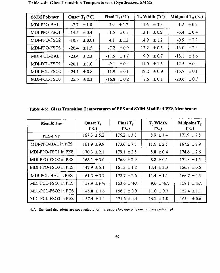
Table 4-4: Glass Transition Temperatures of Synthesized SMMs
SMM Polymer 1 Onset Tg (OC) 1 Final Tg ( O C ) 1 Tg Width ( O C ) 1 Midpoint Tg ( O C )
MDI-PPO-BAL 1 -7.7 1 1 . 8 1 3.9 f 1.7 1 11.6 f 3.5 1 -1.2 1 0 . 2
- -
MDI-PCL-BAL 1 -23.4 f 2.3 1 -13.5 f 1.7 1 9.9 f 0.7 1 -18.1 f 1.6
Table 4-5: Glass Transition Temperatures of PES and SMM Modified PES Membranes
Membrane Onset Tg Final Tg Tg Width 1 M i d g t Tg
PES-PVP 167.3 f 5.2 1 176.2 + 3.8 1 8.9 c 1.4 1 171.9 k 2.8
MDI-PPO-BAL in PES 1 161.9 f 9.9 1 173.6 f 7.8 1 1 1.6 f 2.1 1 167.2 f 8.9
MDI-PPO-FSO1 in PES 1 170.3 + 2.1 1 179.1 + 2.5 1 8.8 f 0.4 1 174.6 f 2.6
NIA - Standard deviations are not available for this sample because only one run was perforrned
. ...
MDI-PPO-FS02 in PES
MDI-PPO-FS03 in PES
MDI-PCL-BAL in PES
MDI-PCL-FSOI in PES
MDI-PCL-FS02 in PES
MDI-PCL-FS03 in PES
168.1 k 3.0
147.9 + 5.1
161.3 f 3.7
153.9 &NIA
145.8 + 1.6
157.4 3- 1.4
176.9 i 2.9
161.3 + 1.8
172.7 + 2.6
163.6 I N / A
156.7 1- 0.9
171.6 i 0 . 4
8.8 f 0.1
13.4 f 3.3
11.4 rt: 1.1
9.6 4 NIA
11.0 1 0 . 7
14.2 i 1.0
171.8 -t- 1.5
156.8 -t 0.6
166.7 f 4.3
159.1 ~ N / A
152.4 f 1.1
165.4 k 0.6

4.3.1 PES FIat Sheet Membranes
The casting method described in Section 3.3.1 allowed for the fabrication of optically smooth
membranes (approximately 40 Fm in thickness). PES membranes without SMM were
transparent films while SMM modified membranes were opaque. However, several SMM
modified membranes showed streaks of thicker polymer close to the edges of the slide. This was
more prominent in membranes with SMMs containing FSO as the fluoro-alcohol as compared to
materials with BA-L. This may be due to the more hydrophilic nature of the FSO component
which contains long PEO segments. Due to the relatively long hydrophilic segments, these
SMMs will be more miscible in the PES material. Instead of migrating to the air interface, some
segments may become entangled within the bulk rnaterial. This would increase the viscosity of
the bulk solution and therefore cause the observed streaks of cast polymer. Only the middle
portions of the surfaces, far from the glass edges, were used for surface analyses.
4.3.2 Characterization of PES Membrane Morphology
4.3.2.1 Polarized Microscopy
Several rnicroscopy techniques were used to study the morphology of cast PES flat sheet
membranes. Polarized rnicroscopy perhaps provided the clearest evidence of microdomains
resulting from SMM addition. PES membranes were clear and transparent, and no
microstructures could be observed through a polarized light microscope. Figure 4-2 illustrates
the microdomains within three SMM modified PES membranes as seen through a polarized
microscope. These pictures suggest that the opaqueness of the membranes is due to spherical
microstructures. There is a sense of depth as some spheres appear reflective, indicative of
microdomains wllich are closer to the surface, whife some which are deeper within the membrane
are black, and others which are even further in depth appear out of focus. The range of diarneters
of the microdomains for selected SMMs are given in Table 4-6. Of the three SMM modified

while materials containing MDI-PPO-BAL had the largest, suggesting that microdomain sizes
depend on individual SMMs.
Figure 4-2: Microdomain Structures of 4 wtOA SMMs within PES Membranes Obsewed Through a Polarized Microscope
(a) MDI-PPO-BAL in PES
(b) MDI-PCL-BAL in PES (c) MDI-PPO-FS03 in PES

When cast PES films were placed undenvater, small bumps were observed on the films, likely
due to the penetration of water through the membrane pores. Confocal microscopy was used to
determine the height of these bumps and to confirm that studies by undenvater contact angles
would not be significantly affected. Figure 4-3(a) is an example of a PES membrane as seen
underwater by confocal microscopy. The image shows optical rings which were caused by the
interference of the light passing through the membrane and reflected in the aqueous medium.
The nurnber of rings observed can be related to the height of these bumps by [Hemsley, 19891:
number of optical rings x wavelength of reflected light Height =
refractive index of water (4- 1 )
The wavelength of light used in this study was 488 nrn and the refractive index of water is 1.3
[Perry et al., 19841. In general, the height of these bumps ranged from 1 pm over a length of 250
p m for the smallest number of rings to 1 1 pm over a distance of 1500 pm for the largest number
of rings. Because the height of these bumps are gradua1 over a large distance, interference from
these bumps on contact angle studies is assumed to be negligible. However, it c m o t be
completely dismissed that some contribution to contact angle hysteresis may come fiom this
effect. Similar observations were made for SMM modified PES membranes undenvater, as
shown in Figure 4-4(b) for 4 wt% MDI-PCL-BAL in PES. In addition, the image in Figure 4-
4(b) indicates that there are microstructures within the SMM modified membranes which are
much smaller in size than the bumps.
The microstructures of the PES materials containing 4 wt% SMM were further studied on dry
membranes using confocal microscopy at a higher magnification. In reflectance mode, the
microdomains are distinct spheres as illustrated in Figure 4-4(a) for MDI-PPO-BAL in PES.
Using confocal microscopy in transmittance mode for the same membrane, the depth of these
microdomairis can be seen as darker patches in Figure 4-4(b). The reflectance mode was

F U I L w & I L I W U V I A ou v V L U A U A I A A V I A A I V U L I I + U l l l ~ l l 1 U L L U 1 b 3 L U l U Lllb 1 l L I ~ l W U W 1 1 1 U 1 1 1 3 111 L L 1 b 3 b 1lllllJ V Q l l C U 111
size for different SMM modification. These data are given in Table 4-6.
Using the confocal microscopy apparatus, it was possible to image different depths within the
membranes by stepping up the microscope stage in 1.2 pm increments. Figure 4-5 illustrates the
dispersion of the spherical microdomain structures at different depths within a PES membrane
containing 4 wt% MDI-PPO-BAL. These results suggest that the microdomain structures are
dispersed throughout the bulk of the membrane materials, penetrating approximately the top
quarter to one third of the membrane on the side of the membrane-air interface. As well, going
deeper within the membrane fiom the top surface, there is a gradua1 depletion in the number of
structures.
Figure 4-3: Confocal Microscopy images of PES Membrane Underwater
(a) PES-PVP Mern brane (b) 4 wt% MDI-PCL-FS03 in PES

Figure 4-4: Confocal Microscopy Images of 4 wt% MDI-PPO-BAL in PES Dry Membrane
(a) Reflectance Mode
(b) Transmittance Mode

Figure 4-5: Confocal Microscopy Images of the Dispersion of Microdomain Structures in a PES Membrane Modified with 4 wt% MDI-PPO-BAL
(a) top surface (b) 3.6 pm from the surface
(c) 6.0 pm from the surface (d) 8.4 pm from the surface

The topography of dry PES and selected SMM modified PES surfaces were fùrther analyzed
using atomic force microscopy in order to confirm the dimensions of domains on the surfaces.
Figure 4-6 illustrates the topography of PES and SMM modified PES membranes as imaged by
atomic force microscopy. While the PES membrane has a relatively srnooth surface, that of the
SMM modified surface consists of hills and valleys. It is suggested by these pictures that SMM
modification creates surfaces with greater texture. The sizes of the features Vary for substrates
with different SMMs (Table 4-6). The height of the hills in the terrrain for al1 of the SMM
modified surfaces studied varied between 4 to 20 nm while the width of these surface features
ranged between 0.2 to 3 .O Pm.
Table 4-6: Sizes Of Microdomains in 4 wt% SMM Modified PES Membranes
1 Dry Membrane ( Range of Diameters in Microdomain Structures (pm) 1
1 MDI-PPO-FS03 in PES 1 0.1 - 0.5 1 0.5 - 1.0 1 N/A 1
MDI-PPO-BAL in PES
MDI-PPO-FSO 1 in PES
MDI-PPO-FS02 in PES
Polarizing
0.5 - 1.5
N I A
N IA
Confocal
1.0 - 2.5
0.5 - 1.5
0.5 - 2.0
AFM
1 .O - 3.0
N I A
N I A

Modified PES ~ e r n b r a k ~ o ~ & a ~ h ~
(a) PES Membrane
(b) 4 wt% MDI-PPO-BAL in PES
(b) 4 wt% MDI-PCL-BAL in PES

The surfaces of selected PES and SMM modified PES films were analyzed by X-ray
photoelectron spectroscopy (XPS) in order to confirm the concentration of fluorine at the surface.
Each film was analyzed at two take off angles, 15" and 90°, corresponding to a depth of analysis
of 30 A and 100 A respectively. For each film, two samples were analyzed and the relative
atornic percentages of fluorine (F), oxygen (O), nitrogen (N), carbon (C), and silicon (Si) are
given in Table 4-7. For non-modified PES films, some contamination of silicon on the surface
was observed but were not present on SMM modified surfaces. The fluorine content on the
surfaces of PES membranes which contained no SMMs were negligible, at no more than two
atomic percent for both take off angles. In contrast, the fluorine content on the surfaces of PES
containing SMMs ranged between 33 and 47 atomic percent at a depth of 30 A, and between 1 7
and 26 atornic percent at a depth of 100 A. Therefore, it is clear that fluorine groups are
concentrated at these sdaces .
When comparing the two different analyzed sites for the sarne sarnple and a specific take off
angle, there are variations in the fluorine contents for some of the surfaces (as much as 10 percent
for MDI-PPO-BAL), while for others the variations are small. This may be due to the
heterogeneity of the surfaces. As shown by AFM analysis, the topography of the modified
membranes consist of microdomain structures ranging from 1 to 2 microns, depending on the
SMM (Table 4-6). The spatial resolution in the XPS analysis is approximately 4-6 mm, and
therefore a particular scan may encompass any fraction of the microdomains, giving variations in
the fluorine content.

Table 4-7: XPS Results of Elemental Composition at the Surfaces of PES and SMM Modified PES Membranes
Membrane Site Ta ke Off
Angle
Relative Atomic Percent
0 1 s 1 N l s
PES-PVP
MDI-PPO-BAL in PES
MDI-PPO-FSO 1 in PES
MDI-PPO-FSO2 in PES
MDI-PPO-FS03 in PES

4.3.4 Contact Angle sruaies
4.3.4.1 Results From Air Contact Angle Analyses
Air contact angle analysis was used to qualitatively assess the relative wettability of PES and
SMM modified PES flat sbeet membranes. The results are shown in Table 4-8. Pure PES shows
an advancing angle of approximately 67" and those for the SMM modified surfaces ranged
between 97" and 120". The addition of the SMMs increased the contact angles of the membrane
surfaces considerably, by as much as 53". Therefore, the SMM-PES surfaces are considerably
more hydrophobic. This is attributed to the presence of the SMMs at the surface of the PES
membranes, and more directly from the hydrophobic nature of the SMM fluorine tails. SMMs
containing PCL segments consistently showed larger advancing contact angles than those with
PPO segments, despite the fact that fluorine content was generally higher for the SMMs with
PPO segments (Table 4-2).
SMMs containing BAL as the fluoro-alcohol produced membranes with larger receding angles
than those with FSO. This may be due to the more hydrophobic nature of BAL, which does not
contain the hydrophilic PEO segments that are present in FSO. There were some difficulties in
measuring the receding angle and this gave some variability in repeated measurements on the
sarne sarnple and between sarnples. This is largely due to the influence of the needle on the
shape of the liquid drop at low volumes, and as well on the accuracy of reading small angles on
the goniorneter. Overall, the addition of SMMs caused an increase in contact angle hysteresis,
which is expected since the addition of SMM in PES creates a chemically heterogeneous system.

l Membrane Water Advancing
Contact Angle (O)
PES-PVP
MDI-PPO-BAL in PES
1 MDI-PPO-FS03 in PES / 97.5 f 1.6 1 12.4 $r 3.3 1 85.1 k 3.7 1
Water Receding Contact Angle (O)
MDI-PPO-FSO 1 in PES
MDI-PPO-FS02 in PES
1 MDI-PCL-BAL in PES ( 113.2 -t- 1.1 1 30.5 + 3.8 1 82.7 + 4.0 1
Contact Angle Hysteresis (O) 1
67.2 + 0.4
107.3 k1.8
1 MDI-PCL-FSOl in PES 1 119.4 k 0.8 1 17.5 f 1.5 1 101.9 f 1.6 1
102.9 + 2.0
106.3 f 2.3
26.0 + 3.7
58.2 zk 4.5
4.3.4.2 Results From Underwater Contact Angle Analyses
41.2 k3 .7
49.1 + 4.8
32.9 t 5.3
24.2 $r 4.6
MDI-PCL-FS02 in PES
MDI-PCL-FS03 in PES
An undenvater contact angle method was used to qualitatively assess the nature and behaviour of
PES and SMM modified PES membranes in an aqueous environment. The cast membranes
were, in general, optically smooth. However, when the films were placed in water, bumps were
observed on the surface which were suspected to be due to the penetration of liquid into the
membrane pores. Confocal microscopy was used to determine that the hydrated films were
indeed smooth undenvater (Section 4.3.2.2).
70.0 15 .7
82.1 -t- 5.1
The contact angle that an air bubble made on the material surface was measured as air was
introduced onto the membrane. Images were taken every second to give a profile of the
advancing and receding behaviour of the bubble on the surface. The field of view was scaled
according to a premeasured grid which was digitized into the memory of the cornputer. For each
picture taken, the cornputer chose ten points along the image of the air bubble and fitted these
points according to a Laplacian curve to determine theoretical values for the experimental image.
112.2 f 0.7
99.7 f 2.8
21.0 f 1 . 2
29.0 f 6.9
91.2 k1.4
70.7 f 7.4

-
angle, contact radius, surface area, and volume. Using these values, data for the contact angle
was plotted against contact radius for each dynarnic contact angle measurement. A typical plot is
shown in Figure 4-7.
For air advancing contact angles, as time (or air volume) increased, the initial contact radius
remained constant with increasing contact angle. Once the contact angle was large enough to
overcorne the surface tension of the membrane, the three phase line moved and the contact radius
increased as the contact angle remained constant. Figure 4-7 illustrates this ideal behaviour of air
advancing on a PES membrane containing 4 wt% MDI-PCL-BAL. For air receding, the opposite
trends were observed as shown in Figure 4-8. In both cases, the contact angle of interest is the
angle which is constant at increasing or decreasing contact radius for advancing and receding
contact angles respectively. For each membrane (with and without SMMs), at least 3 different
slides were prepared for that SMM and for each slide, the advancing and receding angles were
measured three times.
The phase at which the advancing and receding contact angles do not Vary with increasing or
decreasing contact radius was defined by determining the covariance between the contact radius
and contact angle. The covariance of two variables is defined as the expected value of the
product of their deviations fiom their mean [Olson, 19871 and is a measure of how two variables
change together. If x and y are independent, then the covariance is close to zero and the average
of the contact angle values in this region of the contact angle versus radius plot is taken. As well,
the covariance is similar to the linear correlation coefficient which c m be estimated by dividing
the covariance by the product of the individual standard deviations [Olson, 19871. Since there
are no general rules that can be stated as to what values give a strong or weak correlation [Olson,
19871, it was arbitrarily decided that onIy those experiments which gave a covariance of less than
0.01 and standard deviation of Iess than 2 degrees would be reported as reliable data. The data
from this analysis are tabulated in Appendix K and the final contact angles are reported in Table
4-9.

Figure 4-7: Profile of Air Advancing Contact Angles and Contact Radii for 4 wt% MDI-PCL-BAL in PES Flat Sheet Membrane
O 20 40 60 80 100 120 Time (sec)
Figure 4-8: Profile of Air Receding Contact Angles and Contact Radii for 4 wtOh MDI-PCL-BAL in PES Flat Sheet Membrane
120 , - . 0.25
NI.....
15 20 Time (sec)
j +Contact Angle Contact Radius

n y u a t c u I LO I ~ I U U U L U U W J LillV .. -. .... ..-, -ui-iiiC) - D - - - - -
in the PES membranes decreased the air advancing contact angle by as much as 14", therefore
indicating that these surfaces are more hydrophobic. However, this change in hydrophobicity
(between PES and SMM rnodified PES) for the hydrated membranes is not as great as the change
for the dry sarnples (in the air contact angle study) which was as rnuch as 5 2 O (Table 4-8). This
may lend evidence to the mobility of the SMMs in the PES base material, when place in an
aqueous environment.
There were some difficulties associated with the measurement of the air receding contact angles.
Once the three phase line had receded, only a small volume remained, therefore limiting the
number of images that could be taken. It was impossible in some cases to obtain an accurate
receding angle from the few pictures and therefore they are not reported in Table 4-9. However,
in order to provide the reader with some indication of possible receding contact angles for these
surfaces, the range of contact angles observed are included in Table 4-9. The air receding contact
angles were significantly lower in SMM modified membranes than that in pure PES. Again, this
is attributed to the hydrophobic nature of the fluorine containing SMMs. The contact angle
hysteresis values of the membranes undenvater were close to those observed in the air contact
angle study, for both PES and SMM modified PES samples. Using the undenvater air advancing
contact angle values in Table 4-9, the surface tension (y,,) of the PES and SMM modified PES
membrane surfaces were calculated using the macroscopic approach of the equation of state
(Section 2.3.3). The results are shown in Figure 4-9. Hydrated PES membranes have a surface
tension of 68 f 0.6 r n ~ / r n ~ and the addition of SMM reduced the surface tension by as much as 8
r n ~ / r n ~ for MDI-PPO-BAL.

1 Z1Ult: 9'7. I\C;JUiLï4 Ui U i i U G i rr n r c i b u i i r a b r A U ~ L ~ n i i u i j a b u vii i rrv A r = r i i i v i uiirii
1 1 Contact Angle (O) 1 Contact Angle (O)
1 ~ e r n b r a n e ~ Air Advancing Hysteresis (O)
1 PES-PVP 1 157.5 '1.8 1 115.1 11.2
Air Receding
1 MDI-PPO-BAL in PES 1 143.7 f 1.2 1 ~ a n g ' = 53 - 72
Contact Angle
Range = 91 - 72
MDI-PPO-FSO1 in PES
MDI-PPO-FS02 in PES
MDI-PPO-FS03 in PES
Figure 4-9:
MD1-PCL-FS03 in PES
Surface Tension (Y,,) of PES Membranes Underwater
r
148.4 f 0.4
147.3 k l . l
147.7 k1.4
PES MD1 MD1 MD1 MD1 MD1 MD1 PPO PPO P PO PPO PCL PCL BAL FSOI FS02 FS03 BAL FS03
149.0 f 1.9
- -
MDI-PCL-FSOI and MDI-PCL-FS02 were not available for study at the time the undenvater contact angle equipment was available for use and therefore undenvater studies were not performed for these materials. %ue to difficulties in measuring the air receding contact angles, it was not possible to obtain an accurate value for these surfaces. A range is given to provide the reader with an idea of possible values.
60.5 ir 1.1
71.6 f 3.5
Range = 61 - 91
87.9 f 1.2
75.7 I 3 . 7
Range = 87 - 57
Range = 63 - 91 Range = 86 - 58

4.4.1 Hollow Fibre Membranes
The solution casting rnethod (Section 3.4.1) produced PES hollow fibre membranes with
optically smooth surfaces. The hollow fibres for both PES and SMM modified PES were white
as a result of precipitation of the polymer in a gelation bath. The dimensions of the fibres were
determined by photographing magnified images observed through a light microscope and
measuring the circurnference of the fibre tube. The average dimensions of the hollow fibre are:
inner diameter 0.70 f 0.04 mm
outer diameter 0.98 * 0.03 mm
length of tube used 8 _+ 0.5 mm
The total surface area of an 8 mm piece of hollow fibre membrane was 44.98 +_ 2.3 mm2. The
surfaces of the hollow fibre membranes were analyzed by scanning electron microscopy and the
images of a PES and an SMM modified PES membrane are s h o w in Figure 4-10. These images
reveal the presence of contaminants on the surfaces of the membranes for both non modified and
modified membranes. These defects was probably produced during the manufacturing of the
hollow fibres and may ultimately affect the results of blood compatibility studies.
Figure 4-10: SEM Images of Hotlow Fibre Membranes
(a) PES (b) 4 wt% MDI-PPO-BAL in PES

Preliminary blood compatibility evaluation of PES hollow fibre membranes were assessed with
respect to fibrinogen adsorption. The details of the adsorption experiment were given in Section
3.4.2. The nurnber of counts per minute associated with adsorbed '2S~-labelled fibrinogen was
related to the actual adsorbed fibrinogen concentration by the following equation:
net surface counts (cpm) x protein concentration (mg 1 mL) amount adsorbed (mg / cm') = x 1000
surface area (cm2 ) x solution count (cpm / mL)
When the solution counts were analyzed for each experiment, the solution counts for the low
fibrinogen concentration solutions did not have a high degree of correlation to the expected
fibrinogen concentrations. In previous fibrinogen adsorption experiments performed at the
McMaster laboratory, solution counts were only taken for the highest and moderate
concentrations. For al1 other concentrations, solution count values were estimated by
interpolation. This is because solution counts for the low concentrations are too close to the
detection limit of the gamma counter and are therefore more likely to produce errors. Because of
this concern and the fact that solution counts did not relate directly to the expected protein
concentrations, only solution counts for the two highest concentrations were directly used for
calculations.
The different modified surfaces were divided into three sets, and each set was run with different
preparations of radiolabelled fibrinogen. Since different preparations resulted in different
radiolabel levels, a PES control fibre was used in each experiment. Figure 4-1 1 shows the
adsorption of fibrinogen onto PES membranes containing BAL as the fluoro-alcohol. The effect
of FSO fraction on the performance of the SMM with respect to protein adsorption is given in
Figure 4-12 (SMMs synthesized with PPO) and Figure 4-13 (SMMs synthesized with PCL). In
al1 experirnents, it is clear that surface modification with SMMs reduced the amount of protein
adsorption as compared to non-modified PES membranes.

- - - - - - - - - - - - - - - - - - - - 1 - 1 1
between experiments, there may have been slight differences in experimental technique which
caused deviations in the absolute level of fibrinogen adsorption. Evidence of the latter is pointed
out by the fact that the plateau levels for pure PES varied from one experiment to the next.
Therefore, in order to compare the effects of the eight different SMMs on fibrinogen adsorption
as compared to PES, two approaches were used for comparison. The first approach involved
calculating the ratio of adsorption slopes of SMM modified PES to pure non-modified PES,
between the concentrations of 0.01 rng/rnL and 0.05 mg/mL (representing the initial adsorption
phase). The second factor used for comparison is the determination of the percent reduction in
fibrinogen adsorption as compared to pure PES at the highest fibrinogen concentration, 0.5
mg/mL. These data are given in Table 4-10.
The ratio of the adsorption slopes for modified to non-modified membranes are either near unity
or significantly lower than unity. A lower ratio indicates that with increasing protein
concentration, the arnount of protein adsorption is less for the modified membranes. In general,
SMMs having PPO as the soft segment showed a more pronounced reduction in the ratio value at
low fibrinogen concentrations. As well, these SMMs also showed the greatest percent reduction
of fibrinogen adsorption at the highest concentration (0.5 mg/mL). The only exception is that of
PCL with FS02 which also showed a greater reduction in fibrinogen adsorption.

Figure 4-1 1: Fibrinogen Adsorption Ont0 PES Hollow Fibre Membranes -SMM Modifications Containing BAL
i
-+- PES
-D-MDIPPO-BAL in PES ~ --
O 0.1 0.2 0.3 0.4 0.5
Protein Concentration (mglml)
Figure 4-12: Fibrinogen Adsorption Onto PES Hollow Fibre Membranes SMM Modifications Containing PPO and FSO
; + PES I
1 -M-MDI-PPO-FS03 in PES ' 1 + MDI-PPO-FSO~ in PES 1 1 \C MDI-PPO-FSOI in PES /
O 0.1 0.2 0.3 0.4 0.5
Protein Concentration (mglml)

Figure 4-13: Fibrinogen Adsorption Onto PES Hollow Fibre Membranes SMM Modifications Containing PCL and FSO
1 l
--- 1 t ------p. -- t J
O O. 1 0.2 0.3 0.4 0.5
Protein Concentration (mglml)
Table 4-10: Summary of Fibrinogen Adsorption Results for 4 wt% SMM Modified PES Hollow Fibre Membranes
Membrane Ratio of Adsorption Slopes (SMM Modified PES):PES
- -
MDI-PCL-FSO1 in PES 1.04 + 0.20 8.1 t 8.3
Percent Reduction of Fg Adsorption at 0.5 mg/mL 1
-
MDI-PPO-FSO2 in PES
MDI-PPO-FS03 in PES
1 MDI-PCL-FSO2 in PES 1 0.75 -C- 0.18 1 27.2 & 6.7 1
0.92 -t. 0.15
0.83 k0.16
15.7 2 8 . 1
22.5 + 7.2
MDI-PCL-FS03 in PES 0.91 k0.16 5.0 k9.1

The membrane materials were contacted with whole blood in a rocking platform apparatus
(Figure 3-5) for one hour at 37 OC. The blood collected from the test materials were analyzed for
platelet count in the bulk, platelet activation (as indicated by % P-selectin expression and %
microparticles), and leukocyte activation (as indicated by the upregulation of CD1 1 b). Table 4-
11 details the ce11 count and flow cytometric results of platelet activation on these materials as
compared to control samples. The first set of samples are negative controls of resting blood
stored in sealed microcentrifuge tubes during the experiment. Resting and EDTA anticoagulated
sarnples provide an indication of the lower limit of activation. The presence of SFLLRN
thrombin peptide in the blood sarnple will activate platelets to breakdown and form
microparticles and P-selectin expression, and therefore defines the upper lirnit of platelet
activation in the blood. Three control materials were analyzed in the rocking platform apparatus,
relatively non-activating Silastic, relatively activating polyethylene (PE), and non-modified PES
hollow fibre membrane. The modified hollow fibres were separated into two series for these
studies, one group with PPO based SMM modifications and the other with PCL based SMM
modifications. Each series were analyzed in three separate experiments with six different
volunteer blood donors. For the control blood samples and materials, averages and standard
deviations were calculated fiom al1 six experiments and for the test materials (SMM modified
membranes) averages and standard deviations were calculated for three experiments.
In the resting sarnple, the number of platelets in the bulk of the blood is approximately 123 3- 14
(x Io9) per litre. Polyethylene (PE) positive control material showed the lowest platelet counts at
74 + 13 (x 109) per litre indicating the uptake of platelets from whole blood. The platelet counts
for the Silastic@ negative control and PES membrane are comparable, showing only a slight
decrease in the arnount of platelets present relative to resting samples after the rocking
experiment. PES membranes modified with PPO based SMMs also show comparable platelet
nuinbers to that of Silastic@ and PES. However, membranes containing PCL based SMMs
resulted in a reduction in the amount of platelets in blood, comparable to that of PE. There were
no significant differences in this marker between the four modifications within each series.
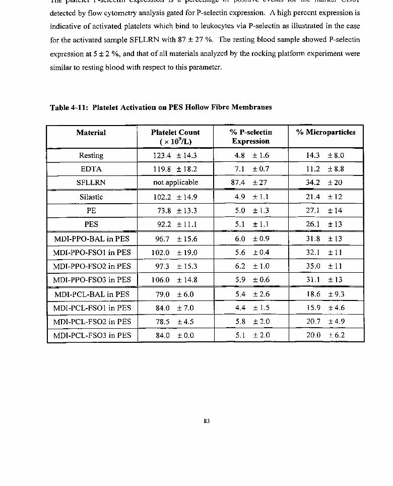
I I I G piaLcicL r-~CICLLIII C A ~ I ~ J J I V I I 13 a pubuIiagb ui p u a i ~ i v b b v b i i ~ a i u i ~ i i b ~licunu L U U ~
detected by flow cytometry analysis gated for P-selectin expression. A high percent expression is
indicative of activated platelets which bind to leukocytes via P-selectin as illustrated in the case
for the activated sample SFLLRN with 87 + 27 %. The resting blood sample showed P-selectin
expression at 5 k 2 %, and that of al1 materials analyzed by the rocking platform experirnent were
similar to resting blood with respect to this parameter.
Table 4-11: Platelet Activation on PES Hollow Fibre Membranes
Material
Resting
EDTA
SFLLRN
O h P-selectin Expression
Platelet Count ( x 1o9n)
Silastic
PE
PES
MDI-PPO-BAL in PES
MDI-PPO-FSO1 in PES
MDI-PPO-FS02 in PES
MDI-PPO-FS03 in PES
MDI-PCL-BAL in PES
MDI-PCL-FSOl in PES
MDI-PCL-FS02 in PES
MDI-PCL-FS03 in PES
% Microparticles
123.4 k 14.3
119.8 k 18.2
not applicable
102.2 + 14.9
73.8 + 13.3
92.2 k l l . l
96.7 f 15.6
102.0 + 19.0
97.3 k15.3
106.0 k 14.8
79.0 i 6.0
84.0 + 7.0
78.5 + 4.5
84.0 k 0.0
4.8 f 1.6
7.1 + 0.7
87.4 k 27
14.3 f 8.0
11.2 '8.8
34.2 k 20
4.9 k l . l
5.0 k1.3
5.1 f 1.1
6.0 k 0.9
5.6 k0.4
6.2 k 1.0
5.9 + 0.6
5.4 f 2 . 6
4.4 k1.5
5.8 52 .0
5.1 k2.0
21.4 L-12
27.1 '14
26.1 f 1 3
31.8 k 13
32.1 -411
35.0 + 11
31.1 k 13
18.6 -t 9.3
15.9 k 4.6
20.7 14 .9
20.0 + 6.2

-
marker CD61 detected by flow cytometry gated for %microparticles. The formation of
microparticles results fiom the fibrinogen binding to GPIIbAIIa in the activation of platelets
momura et al., 19921. The resting samples showed some degree of microparticle formation at 14
k 8 %. Silastic@ and membranes containing PCL based SMMs showed comparable values,
slightly above that of the resting sarnple, although not significant. Resting sample with SFLLRN
activator, PE, PES, and membranes containing PPO based SMMs al1 showed comparable
microparticle formation, at approximately 30%. However, with the variability between
experiments and the large standard deviations in the measurements, the levels of microparticle
formation for al1 materials analyzed by the rocking apparatus were not significantly different.
In the blood sarnples, leukocyte activation was determined by the upregulation of the antibody
CD1 1 b as determined by flow cytornetric analysis. These results are shown for'all controls and
materials in Figure 4-14. The degree of activation of leukocytes associated with platelets is
quantified in terms of a linearized fluorescence unit and are used as relative terms. Both the
relatively non activating Silastic@ and relatively activating PE materials showed the sarne degree
of leukocyte activation as the resting blood sample at approximately 170 units but less than the
PMA activated blood sample. All PES and SMM modified PES membranes showed an
increased amount of leukocyte activation during blood contact. Membranes modified with BAL-
based SMMs appear to lower the arnount of leukocyte activation of PES membranes by as much
as 80 units. In contrast, membranes containing FS02 and FS03 based SMMs showed increased
leukocyte activation as compared to non-modified PES membranes, by as much as 116 units.

Figure 4-14: Leukocyte Activation by the Upregulation of CD1 1 b
Resting EDTA PMA Silastic PE PES MD1 MD1 MD1 MD1 MD1 MD1 MD1 MD1 PPO PPO PPO PPO PCL PCL PCL PCL BAL FSOI FS02 FS03 BAL FSOl FSOZ FS03

5.1 SURFACE MODIFYING MACROMOLECULES (SMMs)
5.1.1 Synthesis of SMMs
Previous work investigating the synthesis of SMMs found that the properties of these oligomers
depended on the reactant mole ratio, reagents used, and environmental conditions [Pham, 1995;
Tang, 19953. It was assumed that by keeping the reaction conditions constant, such as the
reactant mole ratio, apparatus, temperature and stir rate, differences in polymerization between
SMMs would not vary significantly. In that case, the variations between the SMMs and its
effects on the base polymer would be due to their individual chernical composition. An
investigation on the reproducibility of the synthesized SMMs was beyond the scope of this thesis.
It is important to note that only one batch of each type of SMM was synthesized and analyzed,
and therefore conclusions drawn fiom the data presented should be confinned with M e r
studies on additional batches of SMMs.
In the synthesis of commercial polyurethanes, it is desirable to produce polymers with high
molecular weight through chain extension with a di01 or diamine. This is because the final
application of the polywethane is often one that requires mechanical strength and integrity.
However, in this study, this factor is not as important since SMMs are used as an additive in
small weight fractions relative to the base poIymer. The properties that are important are the
miscibility of the SMMs with the base polymer and the characteristics which may dictate the
SMM7s stability at the material surface. Therefore, the reagents used in synthesis were chosen
for the purpose of distinguishing the effect of different soft segments and fluoro-alcohol
endcapping reagents. The influence of these components on the nature of SMM interactions,
within the main chain of the base polymer, was of particular interest. For exarnple, a high
molecular weight SMM may result in entanglements within the base polymer and reduce the
driving force for the SMMs to migrate to the surface. At the same tirne, however, if the SMMs

possibility for leaching of the additives from the base material.
The fluoro-alchohols, BAL and FSO-100, were commercial products which contained unknown
impurities. The low molecular weight fractions of BAL, FSOl and FS02 were believed to be
relatively pure and free of contaminants because these were recovered products from distillation
of the stock materials. However, FS03 was the residual fraction from distillation and therefore
would have contained unknown contaminants. When PES solutions containing FS03 based
SMMs were filtered through a 0.5 pm filter, brown particulates were observed on the filter paper.
This may have been irnpurities from the original FS03 fraction which did not react to form SMM
polymer. Sirnilar particulates were also recovered from FS03 during the purification of FSO
fractions [Weiler, 19971. Approximately one third of FSO-100 was purified as FS02, and only
one tenth of FS02 was recovered as FSOl. Furthemore, the latter fraction was often difficult to
recover fiom the FS02 phase because the boiling point range was not clear and the products were
only differentiated by slight colour variations (clear for FSOl and faint yellow for FS02).
Considering the difficulties associated with the processing of FSO-100, future manufacturing
work with this materiai should use a combination of FS02/FSOl (the distillation product of
FSO-100) since it contains less contarninants and is relatively easy to recover. Characterization
results indicating that FSOl and FS02 produce SMMs with similar properties fürther support
this approach.
The SMMs differed in physical character and this defined their ease of handling during
processing. After the precipitation of the polymer solution in distilled water, SMMs containing
BAL tended to give polymers which were elastomeric while those containing FSO tended to be
tacky powders. During the final washing stage with 30% acetone, al1 SMMs became more tacky
because the polymers were partially soluble in acetone. Processing at this stage became difficult
because the polymers would stick to the sides of the container and the stir blade. After the final
wash, the polymers had to be scraped frorn the sides of the beaker and as a resuIt, the final
polymer yield was considerably low. The acetone washing step was implemented to leach out
residual unreacted monomers, specifically fluoro-alcohols, which are soluble in acetone.

V W I I O L U ~ L L L ~ ~ ulr ~11~1115~ ALI A I L L G ~ ~ I A L ~ VI CIIC, )JULJIIIC,I a I 1 u I U W YILIU, I L 13 I~~ U I I L I I I G I I U C U illa1 a
different washing solution be used. Other possible solvents include ethyl acetate and toluene
which also dissolves the fluoro-alcohol monomers [Dupont]. Further work is required in order to
determine the solubility of the SMM polymers in these solvents.
5.1.2 Properties of SMM Polymers
The properties of eight SMM polymers synthesized in this study were characterized by physical
appearance, elemental composition, molecular weights, and thermal properties. The effects of
using different polyol and fluoro-alcohol reagents on each of these properties are described in
this section.
5.1.2.1 Physical Appearance
The physical appearances of the final processed SMM polymers are dependent on both the nature
of the sofi segment and the fluorine tails. The PPO based SMM materials were more tacky as
compared to the PCL based polymers. Since the structure of the polymer is dependant on the
main urethane prepolymer chain, this observation may be due to the higher molecular weight of
the PCL segment (MW=530) which generally produced SMMs with larger molecular weights
than the PPO equivalents (MW=425). Since SMMs are oligomeric fluoro-polymers with a
relatively short main chain, one would expect the fluorinated endgroups to have an effect on the
main polymer structure. The low molecular weight fluoro-alcohols (FSOl, FS02 and BAL)
tended to be associated with less elastomeric SMMs having a crystalline appearance.
5.1.2.2 Elemental Composition
The structure of BAL is known from the literature [Dupont] and was confirmed in the work of
Pham 119951. However, the molecular weights of the three FSO fractions were not provided by
the supplier of the stock FSO-100. In a previous study, sainples were sent to Guelph Chernical

LaDoratories Tor eiemenrai anaiysis on r;aroon, i iuorinc, a i u uxygt;~ w GUCL, 1 77 1 1. 1 HG LCSUILS
are given in Table 5-1.
Table 5-1: Elemental Composition of FSO-100 Fractions [Weiler, 19971
The molecular structure of FSO-100 is:
FSO Fraction
FSO l
where m ranges from 3 to 8 [Dupont]. Different combinations of m and n values were used to
determine possible chemical structures for the three FSO fractions with elemental compositions
matching that given in Table 5-1. The possibilities are given in Table 5-2. The average
molecular weight of FSO-100 stock solution is 730 [Dupont]. Since two thirds of the stock
material were obtained as FS03, it is assumed that the average molecular weight of this fraction
must be higher than 730. Based on Table 5-2, this value would be estimated at 860. The lower
molecular weight fractions would most likely be lower than 730. For FS02, the average
molecular weight should be at least as low as 628. It is believed that the molecular weight of
FSOl is close to that of FS02 due to difficulties in separating the two fractions by distillation.
Therefore, the molecular weight of FSOl would likely be 596. From this reasoning, the
molecular structures of the three FSO fractions are given in Table 5-3. While these molecular
weights are not believed to be exact, they are probably good first estimates. Future work could
confirrn this by analyzing pure FSOl and FS02 by mass spectroscopy. They are discussed here
in order to give the reader an idea of their molecular structures and how they might influence the
structure of the different SMMs.
wt% Carbon
31.7
wt% Oxygen
1 1 . 1
wtOh FIuorine
54.0

FSO Fraction m n Molecular Weight
FSOl 3 2 452
4 3 596
Table 5-3: Estimates of Average Molecular Structures of FSO Fractions as Determined by Elemental Analysis
Theoretical elemental compositions of the SMMs were calculated using approximate molecular
weights of each reagent (based on Table 3-1 and Table 5-3) and assuming a perfect 3:2:2
stiochiometric ratio of MDI:polyol:fluoro-alcohol. The theoretical elemental compositions of
nitrogen and fluorine in the SMMs are given in Table 5-4, and the experimental values are also
tabulated for cornparison. The composition of nitrogen is indicative of the incorporation of MD1
in the main chaiil during the prepolymer reaction and the composition of fluorine corresponds to
the relative arnounts of fluoro-alcohol in the SMM.
FSO Fraction
FSOl
FS02
FS03
Molecular Structure
F(CF2CF2)4CH2CH20(CH2CH20)3H
F(CF2CF2)3CH2CH20(CH2CH20)6H
F(CF2CF2)4CH2CH20(CH2CH20)9H
Molecular Weight
596
628
860

of Elemental Nitrogen and Fluorine in SMMs
wt% Nitrogen 1 wt% Fluorine
1 Theoretical 1 Ex perimental ( Theoretical
MDI-PPO-FSO 1 1
Experimental
MDI-PCL-BAL
MDI-PCL-FSO 1
Comparing experimental theoretical compositions, the fluorine contents for SMMs containing
BAL and FS03 were lower than expected, with the BAL based SMMs showing the greatest
deviation. For the sarne SMMs, the composition of nitrogen was slightly greater than expected
(with the exception of MDI-PPO-BAL), suggesting that prepolymer content was relatively larger
than that predicted by theory. Interestingly, the SMMs which showed the greatest deviation from
theoretical values were the three SMMs (MDI-PPO-BAL, MDI-PCL-BAL, and MDI-PCL-FS03)
with the highest molecular weights (Table 4-3). This trend was also observed in previous studies
on the synthesis of SMMs [Tang, 19951. The results indicate that the urethane prepolymer has a
greater degree of polymerization, than the expected 3:2 for MD1:polyol.
the prepolymer stage, polyol molecules are still present in solution and
with the fluoroalcohols for the isocyanate groups of MDI.
3 .O
2.7
This may
therefore
occur if afier
will compete
3.5
2.9
The elemental compositions for synthesized SMMs containing FSOl and FS02 are close to
theoretical values suggesting that these SMMs exhibit the expected 3:2:2 stoichiometry of
reactants used. The differences between the experimental and theoretical fluorine content in
Table 5-4 suggest th.e relative reactivity of fluoro-alcohols with MD1 to be in the order of FS02 >
23.1
21.1

- - - A .
have a large effect on the endcapping reaction. This is because in step growth polymerization,
the reaction is dependent on the end functional groups of both molecules [Rosen, 19931. In this
case, these would be the hydroxyl group of the fluoro-alcohol and the isocyanate group of MDI.
5.1.2.3 Molecular Weight
The rnolecular weights of the SMMs ranged between 1.8 x 1 o4 and 3.1 x 1 o4 (Table 4-4). In the
previous section, it was suggested that the increase in molecular weights between the different
SMMs was due to an increase in the prepolymer chain. The polydispersity index, or breadth of
molecular weight distribution, of the SMMs are close to 1.3 indicating a very narrow distribution.
This index for most commercial polymers ranges between 2 and 50 [Rosen, 19931. The n m o w
distribution is likely attributed to the low degree of polymerization (degree of polymerization of
2 for a 3:2:2 stoichiometry) of the SMM polymers.
The rneasured polystyrene average molecular weights are much higher than expected values for
the actual SMM polymers having a 3:2:2 stoichiornetric ratio. This is because molecular weights
were determined by a polystyrene calibration curve. Different polymer molecules in the same
solvent exhibit varying configurations depending on their solubility characteristics in that solvent
[Rosen, 19931. Since polystyrene is a homopolymer, polystyrene of varying rnolecular weights
c m be readily synthesized. Because SMMs are block copolymers, it would be difficult to
produce a series of polymers with varying molecular weights in order to construct a calibration
curve. In this work, the SMMs are assumed to be linear polymers, similar to polystyrene, and
polystyrene equivalent moiecular weights are reported for comparison between the different
SMMs.

The midpoint glass transition temperatures of the SMMs ranged between -20 and -1 OC,
indicating that at room temperature the chain segments of the polymers are mobile and the
material is ductile. In general, glass transition temperatures of polymers increase with increasing
molecular weight [Turi, 19811. This relationship was not observed between the molecular
weights (Table 4-4) and Tg values (Table 4-5) for the different SMMs since no general trends
were noted. This may be due to the heterogeneity of the SMMs, whereby the Tg of each segment
contributed to the overall Tg of the polymer. The microheterogeneity in the composition of the
SMMs was also reflected in their Tg widths which ranged between 9 and 15 OC. No other
thermal transitions were detected in the thennograrns, and therefore the SMMs are amorphous in
this temperature range. In general, the T,s (onset, rnidpoint, and final) for SMMs containing
PCL soft segments were lower than those for SMMs containing PPO. This confirms the finding
of previous studies on SMMs showing that the Tg of SMM polyrners are dependent on the polyol
soft segment [Tang, 19951 and furthemore that the Tg decreases with increasing molecular
weights of the soft segment [Petrovic, 1985; Weiler, 19971.
5.2 SMM-PES MEMBRANE COMPOSITION AND MORPHOLOGY
DSC analysis of cast PES membranes showed large fluctuations above 170 OC in the first thermal
scan. Through TGA analysis of the pure components (SMM, PES and PVP), it was concluded
that the fluctuations were due to the evaporation of residual solvent from the membrane films.
This discovery was surprising since the drying procedure of the membranes involved an
evaporation step in a 50 OC oven for 2 days and further drying under vacuum at 50 OC for 2 days.
This finding highlights the difficulty in drying polymer sarnples and evaporating solvent from a
polymer matrix. It was observed by TGA analysis that films which were pour cast in aluminum
plates contained more solvent than films which were dip cast on glass slides (Appendix 1, Figure
1-5). This was probably due to a thinner membrane film obtained by the latter method. It is
important to consider the presence of residual solvent in regards to the outcome of the various

experimems i r i iriis LIICSIS. ru1 ~xal~iplt;, 111 L U I I L ~ ~ L L illlgl~ ~ L U U I C ~ , r i i c icauiiiig ur aul v c i i ~ i i i r u L ~ I G
water phase rnay cause perturbations in the observed contact angles. In blood studies, the
presence of residual solvent rnay cause the destruction of blood cells or activate platelets and
other biological factors. Therefore, care should be taken to ensure that al1 solvent has been
removed from the polymer films.
The addition of SMMs in PES lowered the midpoint Tg of the modified membranes by not more
than 20 OC. This was expected because the SMM additives, which have low Tg values, act to
decrease the Tg of the base polymer. Hence, for well mixed blends, the final Tg of the polyrneric
material would be expected to fa11 somewhere between the values of the two pure components.
However, the mixing of the blends rnay not be immediately obvious because while PES
membranes were originally transparent, they became opaque with the addition of SMMs. The
miscibility of polymer blends is ofien determined by the measure of a single Tg as a function of
composition [Couchman, 1978; Aubin, 19881. Since only one Tg was observed for the modified
membranes (Appendix H), one rnay conclude that the SMMs were miscible in the PES material.
However, the microscopy analysis of PES-SMM membranes reveal the existence of phase
separated structures in the form of spherical microdomains. The single observable Tg rnay result
from the low concentration of SMMs (4 wtO/o) in the bulk material and therefore a distinct Tg for
the SMM phases was not detected. Therefore, the addition of SMMs do not have a significant
effect on this bulk property of the PES material.
The Tg width of the bulk material can provide an indication of the heterogeneity of the
membranes. Non-modified PES membranes showed a Tg width of 8.9 t 1.4 OC. This rnay be
due to the distribution of molecular weight chains of the material and also to the presence of PVP
in the membranes. In general, the addition of SMMs did not significantly increase the Tg width,
again indicating that a low concentration of SMMs did not increase the bulk heterogeneity of the
PES membrane. The importance of concentration has been previously described for two phase
systems containing a low concentration of one component in another [Olabisi, 19791.

homogeneous. However, observations of cast SMM-PES films by polarizing and confocal
microscopy confirm the existence of phase separated microdomains within the PES material
(Section 4.3.2). The domains are spherical and evenly dispersed at several layers through the
bulk of the membranes, with a greater density of microspheres at the surface. The degree of
miscibility of the SMMs in PES will be expected to influence the size of these microstructures,
their dispersion throughout the bulk, and the heterogeneity of the membrane surface.
The immiscibility of two polymers in a polymer blend has been previously s h o w to produce a
system of small spherical microdomains of the low fraction polymer in the rich phase of the
second polymer [Piirma, 19921. The formation of these spherical domains is due to the
difference in the interfacial tension of the two polymers. Hence, it is possible that if one polymer
is considerably more hydrophobic than the other, the driving force for the more hydrophobic
material to phase separate into domains is greater. For exarnple, in a study by Okano et al.
[1981], spherical microdomain structures were observed in phase separated copolymers
composed of hydrophilic 2-hydroxyethyl methacrylate (HEMA) and hydrophobic styrene. In
their study, the microdomains were composed of concentrated hydrophobic styrene chains within
a continuous phase of HEMA chains, even at a mole fraction of 0.35 of the more hydrophilic
HEMA. This emphasizes the ability of hydrophobic molecules to aggregate and form
microdomains.
It is proposed that the observed microdomains in the modified PES materials are SMM
aggregates in the forrn of micelles, resulting from the arnphiphilic nature of the fluorine tail and
long chain backbone. This proposed structure is analogous to the micelle formation of
surfactants in solution. Based on bond lengths for C-C and C-O [Zumdahl, 19893 and the
theoretical structure of the SMMs, if the microdomains were one SMM molecule in dimension,
the size of the microstructures would be in the range of 0.05 - 0.1 Pm. However, the
microdomains obsei-ved in this study are larger, approximately ten times, and therefore the
domains must consist of many SMM molecules. The number of molecules would be difficult to
determine since the specific orientation of the SMMs in the domains is not known.

Lumucal mu p v ~ a r ~ ~ t ; ~ IIIILIUSGU~~ SLUUIGY 1t;vt;alcu LIK SILL VI L I I I L L U U V I I L Q I I I ~ 111 r CD LU v a y
between the different SMMs (Table 4-6). This phenornena rnay reflect the different surface
energies of the individual SMMs [Piirrna, 19921 and their relative miscibility of chain segments
in the base polymer. As well, the molecular weights of the additives may also be a factor
[Hwang, 19951. For exarnple, bIock copolymers with low surface energy segments of siloxane-
and perfiuoroalkane- modified blocks have been previously shown to segregate when mixed with
a styrene homopolymer. The behaviour of the macromolecules depended on both additive
molecular weight and the processing conditions of the blend [Hwang, 19951. Surface
modifications with SMMs containing PPO soft segments exhibited larger microdomain
structures than those with PCL (Table 4-6). Comparing the images of MDI-PPO-BAL and MDI-
PCL-BAL modified membranes (Figure 4-2), it appears that the PCL component increased the
miscibility of the SMMs in the PES material. It has been suggested that PCL is capable of
hydrogen bonding with molecules containing an electron donating portion [Olabisi, 19791 as
illustrated by PCL and PVC miscible blends. In this case, hydrogen bonding results from the
donating character of Cl-C-H groups as shown in Figure 5-1 (a). An analogy may be made for
possible hydrogen bonding between PCL and PVP rnolecules in PES material as illustrated in
Figure 5-1 (b). The XPS data (Table 4-7) showed the presence of nitrogen in the non-modified
PES sample. This suggests that PVP was available at the surface to interact with the SMMs and
the PES. Hence, this may help to explain the greater miscibility of PCL based SMMs in PES as
compared to PPO based SMMs, since PPO segments would not have the same capacity to
interact with PVP.
Figure 5-1: Illustration of Hydrogen Bonding Capabilities of PCL Components
PVC
-(CH 3)5-C -O - II
PCL coniponent O

with FSO (Table 4-6). This may be explained in terms of relative hydrophobic character. The
more hydrophobic BAL based SMMs (as indicated by the chemical data structures for BAL and
FSO Table 3-1) resulted in larger microdomains than the relativefy more hydrophilic FSO based
materials. It is betieved that the PEO segments present in the FSO chains may improve its
miscibility with the PES material, thereby reducing the driving force to form SMM domain
structures. This in tuni should effectively reduce the domain size. The influence of an increase in
PEO segments on irnproving the miscibility of the SMMs is further suggested by the observation
of smaller domain structures for the FS03 based materials relative to those containing FSOl and
FS02.
Confocal microscopy (Section 4.3.2.2) revealed that microdomains were dispersed in the top
third of the cast membrane (ie. top 12 pm) with a gradua1 depletion of the micro-structures from
the surface going into the bulk material. This observation supports the hypothesis that during
membrane casting, the SMMs migrate to the air-surface interface. Based on AFM studies
(Section 4.3.2.3), the topography of the SMM-PES films also indicated the presence of SMM
microdomains on the surface (Figure 4-7). This observation was fùrther confirrned by XPS
elemental studies which showed an elevated concentration of atomic fluorine at the SMM
modified membrane surfaces. The AFM studies also confirmed the size of the surface micro-
structures to be similar to that observed in the bulk of the membranes observed by confocal
microscopy (Table 4-6).
From the microscopy results, a simplified mode1 showing the hypothesized organization of
SMMs in PES membranes (dry surfaces) is illustrated in Figure 5-2. The SMMs are aggregated
into micelle structures dispersed in the bulk PES material. The ring structure is based on
micellar formations analogous to that of surfactants, but the true structure of the core of the
SMM micelles has not yet been determined. The SMM domains are also shown to be exposed at
the membrane surface, as revealed by AFM studies. It is apparent from the diagram that XPS
surface analysis (limit of resolution is 10- 150 prn [Cooke et al., 19961) would not have the lateral
sensitivity to measure the chemical composition of individual microstructures, since any fraction

PES membrane l
-- - . .-
SMM micelle SMM micelle at the surface
surface modifying rnacromolecule
fluorine tail
urethane prspolymer chain
fluorine tail
of the microdomains in PES can be detected at any particular site. At the surface, it is
hypothesized that there is a reorganization of some SMM molecules in which the fluorine tails
are exposed at the surface. This is suggested by XPS studies (Table 4-7) which showed a high
elemental fluorine content at the surface. XPS also revealed a low concentration of elemental
nitrogen at the membrane surfaces, with an increase going deeper in into the material. Recall that
nitrogen is specifically associated with the main cliain of the SMM. Therefore, this suggests that
at least part of the SMM backbone chain is exposed. This was observed in a previous study on

very little sulfur content at the surface which would have been associated with PES,
approximately 1 atomic percent. Therefore, the surface contains high concentrations of other
components which may include SMM and PVP. It is hypothesized that the matrix substrate at
the surface (shown as blank space on the surface of the membrane in Figure 5-2) may contain
SMM molecules and PVP at the top few angstroms. If this is the case, it would not have been
detected by AFM studies. Further studies using spectroscopy techniques capable of high lateral
resolutions will be required to confirm this.
The observed heterogeneity of the modified surfaces may explain observations in other studies
conducted in this thesis. For example, the observed hysteresis behveen the advancing and
receding contact angles is considered to be a measure of the degree of heterogeneity at the
surface. In XPS studies, variations in the relative atornic percent of fluorine are also suspected to
result from the presence of SMM domains concentrated on the surface. The variations were
greatest for membranes containing MDI-PPO-BAL which have exhibited the largest
microdomain structures. For membranes containing the smaller microdomains, elemental
compositions at the surface for different analyzed sites were less variable. The heterogeneity of
the SMM-PES surfaces is also expected to influence blood studies. This has been suggested by
Okano et al. [1981], whose studies showed that the hydrophobic/hydrophilic nature of a surface
affects the pattern of platelet spreading and deformation ont0 these surfaces.
5.3 MEMBRANE SURFACE PROPERTIES
5.3.1 Review of Contact Angle Methods
5.3.1.1 Air Contact Angle Method Using a Goniorneter
Difficulties associated with measuring contact angles using a goniorneter resulted from botli the
nature of the surfaces and the apparatus. The chemical heterogeneity of the membrane surfaces

resulted in a "slip-stick" action of the water droplet. That is, as the volume of the water drop was
slowly increased, the three phase line did not advance slowly, but moved abruptly. The kinetic
energy due to this abrupt motion would have ultimately affected the equilibrium of the system.
There were also sources of errors inherent in the goniometer method for measuring contact
angles. The needle used to advance the liquid rernained in the droplet during measurement and
therefore interfered with its shape. The water tended to one side of the needle, and both the lefi
and right contact angles did not necessarily give the same readings. To account for this, both the
left and right contact angles were measured and averaged if the differencce between the two was
less than five degrees. Measurements with greater than five degree differences were rejected. In
addition, the manually operated syringe caused slight vibrations which may have interfered with
the equilibrium of the liquid drop and therefore the equilibrium contact angle measurements. As
a result of these complications, subsequent work for undenivater contact angle studies used an
apparatus designed to alleviate some of these problems.
5.3.1.2 Underwater Contact Angle Method
(i) Advantages of the Underwater Apparatus
There were several advantages to the undenvater apparatus. First, the needle was placed on the
opposite side of the surface analyzed and therefore did not interfere with the shape of the air
bubble. This was important in order to allow the air bubbIe to advance and recede uniformly as
well as allowing the system to reach equilibrium. The use of a TeflonB needle also eliminated
any vibrations which may have been caused by the operation of the syringe. A constant flowrate
of air was delivered by the use of a motorized syringe so that the rate of the advancing and
receding angles could be controlled. In this manner, the air couid be introduced slowly so as to
minimize the effect of kinetic energy on the equilibration of the system. The behaviour of the air
bubble could be monitored at different time intervals by using the autoinated computer program,
ADSA-P. This program alIowed for accurate and quick calculations of the contact angles and
other parameters, and errors due to visual readings of the contact angles would be eliminated.

There were difficulties in measuring contact angles due to the chemical nature of the membrane
surfaces. The ideal relationship between contact angle and contact radius illustrated in Figure 4-
7 and Figure 4-8 were not always observed. It has been suggested that the contact angle is
dependent on the contact radius as a result of line tension, the one dimensional analog of surface
tension [Neumann, 19961. This effect is illustrated for a PES sample in Figure 5-3, and this
behaviour was also observed for some SMM modified samples. As the three phase line moved
(or contact radius increased), line tension would act in the opposite direction of the motion of the
three phase line. Therefore, the contact angle did not remain constant.
A second problem was the "slip-stick" behaviour of the three phase line which did not advance
slowly on the surface, but moved abruptly to a new position. This action is clearly illustrated in
Figures 5-4 and 5-5 for advancing and receding angles respectively. It was difficult to determine
the correct equilibriurn contact angle on these surfaces since the angle did not remain constant
and would be greatly affected by the kinetic energy of the moving three phase line. This "slip-
stick" behaviour may reflect the chernical heterogeneity of the SMM modified surfaces as
revealed by AFM and XPS studies.
There were mechanical problems inherent in the underwater contact angle method. It was
difficult to centre the air bubble around the hole since the bubble tended to float to one side. To
prevent this, an initial air bubble was introduced and moved to the centre using an inverted
stainless steel rod. The air bubble could then be advanced and receded using the motorized
syringe. For air receding angles, once the air had receded and the motor was stopped, buoyancy
effects created a back pressure which caused the complete withdrawal of the air. As a result, few
pictures of the receding angle were taken and the angle was affected by the kinetic energy of the
receding air bubble.

Figure 5-3: Dependence of Air Advancing Contact Angle on
O 50 100 150 200 250 Tirne (sec)
Figure 5-4: Illustration of Slip-Stick Action of Air Advancing Contact Angles on 4 wt% MDI-PPO-FSO2 in PES Flat Sheet Membrane
t i . 0.1 10 15 20 25 30 35 40 45 50
Time (sec)
1 +Contact Angle . Contact Radius 1

Figure 5-5: Illustration of Slip-Stick Action of Air Receding Contact Angles on 4 wt% MDI-PPO-FS03 in PES Flat Sheet Membrane
O 5 1 O 15 20 25 30 Time (sec)
5.3.2 Surface Energetics of PES and SMM Modified Membranes
Contact angle studies in air and underwater confirrned that the addition of SMMs to PES creates
a more hydrophobic surface than pure PES. Membranes containing SMMs synthesized with PCL
segments showed larger advancing contact angles in air than membranes with SMMs having
PPO based segments (Table 4-8), despite the greater fluorine content in PPO based SMMs (Table
4-2). This may be due to the greater hydrophobic character of PCL sofi segments (a polyester) as
compared to PPO sofi segments (a polyether). If some fraction of the SMM backbone is exposed
at the membrane surface, as suggested by XPS data, then PCL surface modifications may be
expected to yield more hydrophobic surfaces.
The SMM modified surfaces showed a greater contact angle hysteresis, indicating that the
modified surfaces are more heterogeneous than the pure PES. This observation is expected for a
two phase system [Morra, 19901. AFM analysis of the membranes indicated that the films were

- - - - - - - - - - -
surface roughness may be neglected. However, chernical heterogeneity was observed by both
polarizing and confocal microscopy. This was observed in the form of spherical microdomains,
0.1 to 3 pm in size, concentrated at the air interphase which would be anticipated to contribute to
a high degree of contact angle hysteresis [Morra, 19901.
In the aqueous environment, the degree of hydrophobicity decreased in the SMM-PES surfaces as
compared to surfaces in an air environment. This observation is hypothesized to be related to
two possible events, the penetration of water into the membrane pores and polymer surface
dynarnics, both of which are believed to have sorne contribution. The first hypothesis is that in
an aqueous environment, the water molecules are penetrating the interstitial areas of the PES
matrix and therefore, the water rnolecules on the surface would enhance the hydrophilic nature of
the membranes. The tendency of water to penetrate into the membrane pores has been observed
in several studies [Morra, 1990; Holly, 19751, and was confimed in this study by the observation
that membranes cast on glass slides would readily be displaced when immersed in water. As
well, confocal microscopy of membranes undenvater showed areas of swelling (Section 4.3.2.2)
which were suspected to result fiom water passing through the membranes. One can argue,
however that if the observed microdomain structures are concentrated SMMs, the water
molecules would be repelled from these regions and only enter regions of concentrated PES.
Therefore, the surface would be made up of regions of SMMs and water molecules and the
difference in surface energetics, or heterogeneity, between the two phases would be even greater
than that of SMMs and PES. In this scenario, the contact angle hysteresis should be greater in an
aqueous environment as compared to an air environment. However, this was not observed. The
contact angle hysteresis for air and undenvater contact angle studies were comparable (Table 4-8
and Table 4-9). Hence, other factors must be present.
Another factor to consider in regard to the observed decrease in hydrophobicity for hydrated is
related to the mobility of the SMMs in the PES base material. In an aqueous environment, the
hydrophobic fluorine tails would be expected to orient away from the water interphase and
rearrange into the material. Such mobility of chain segments and even whole macromolecules

- - -- - - - - - -
introduction of an air bubble on a hydrated membrane provided the driving force for the
hydrophobic SMM fluorine tails to orient towards the air-surface interface. Since there is a finite
time required for the polymer segments or molecules to rearrange in a changing environment,
then equilibrium contact angles will not be achieved. In this case, the true equilibriurn contact
angle cannot be obtained. Further undenvater contact angle studies should be conducted to
determine the effective hydration time of the SMM modified and non-modified porous
membranes. This factor has particular relevance in biornaterial applications. If the surface of a
biomedical device can undergo reorientation in an aqueous environment prior to and following
protein adsorption, this will have an impact on blood compatibility. As well, packaging and
storage conditions will be important parameters to consider for defining the initial surface
character of the product.
5.4 EFFECTS OF SMMs ON THE BLOOD COMPATIBILITY OF PES MEMBRANES
5.4.1 Properties of the PES Hollow Fibre Membranes
Hollow fibre membranes were fabricated and used for blood compatibility studies for two
reasons. The hollow fibre membranes are easier to handle in an aqueous medium because flat
sheet membranes tended to either displace from its substrate or float in water. As well, the
hollow fibre configuration resembles design components that are incorporated into devices used
for biomedical applications, such as the hollow fibres in a dialysis unit or the hollow tubing of
polymeric catheters.
The study of the membrane morphology (Section 4.3.2) was performed on flat sheet membranes
which were translucent and observable by light microscopes. Unfortunately, the hollow fibre
membranes had a much greater thickness and could not be studied by the same rnicroscopy
techniques because light could not pass through them. Therefore, the presence of rnicrodomai~~s
at the surface and in the bulk of the hollow fibre membranes have not been confirmed. The
behaviour of the SMMs are expected to be similar, although may not be identical, to that of flat

predominantly dependent on the polymer molecular weights and interfacial tensions of the
SMMs. The principle differences in the two configurations, flat sheet versus hollow tube, are
membrane thickness and processing conditions. The thickness of the membrane may affect
phase separation of the SMM and the ability of the SMM to migrate to the membrane interface.
Processing conditions include the precipitating medium (which will have different interfacial
tensions for air and water medium), the curing temperature (which will affect the degree of
phase separation), and the apparatus used to process the sample (which will affect the quality of
the membranes).
Analysis of the hollow fibres by SEM revealed irregular roughness features on the surfaces. The
membranes showed striations in the morphology which may have resulted frorn the machining of
the spinneret component (Appendix F). The grooves and crevices of these materials is expected
to influence the results of the fibrinogen and blood contact studies.
5.4.2 Fibrinogen Adsorption
Fibrinogen adsorption isotherm experiments were conducted to determine the qualitative nature
of protein adsorption ont0 PES fibres and to determine the effects of SMM surface modifications
on the arnount of protein adsorbed at different concentrations. The in vitro experiment was
simple in its implementation and allowed for a quick assessrnent of fibrinogen adsorption ont0
hollow fibre materiais. In the experiment, there was uncertainty about the amount of fibrinogen
that was effectively radiolabeled with 12? during the iodination step. To account for this, PES
samples were run in every experiment. In cornparing the amount of fibrinogen adsorbed onto
non-modified PES control membranes, the three experiments showed reproducible results, with a
variation of approximately 10%. While the experiment was designed to give only fibrinogen
adsorption values for a non-flow and single protein solution, the results do provide some
indication of the potential for the materials to induce interactions with procoagulant proteins.
However, it is noted that the experiment does not account for other factors involved with in vivo

in adsorption and desorption of proteins at the surfaces, as well as their interactions with cells.
The adsorption of fibrinogen proteins on solid surfaces generally follows the characteristics of a
Langmuir isotherm [Horbett, 19861. While the incrernental amount of fibrinogen adsorbed did
decrease with increasing solution concentration, the amount of fibrinogen adsorbed ont0 the
fibres did not level off for the concentration range studied (Figures 4- 1 2,4- 1 3,4- 14). The trends
do appear to approach saturation and hence, the amount of protein adsorbed is expected to level
off at higher concentrations. Future experiments should extend the study to higher protein
concentrations in order to determine the true saturation values. The arnount of fibrinogen
adsorbed by the PES materials (at the highest protein concentration) is higher, although on the
sarne order, as fibrinogen adsorption results reported on other polymer surfaces such as
polyethylene (at 1.4 pg/crn2) and polystyrene (at 1.7 pg/cm2) [Brash, 19691. The higher values
observed in the current study may be a reflection of the increased surface areas due to surface
defects, since this was not accounted for in the original estimate of membrane surface area.
The fibrinogen adsorption studies showed that in most cases, the surface modification of PES
hollow fibre membranes with SMMs reduced the arnount of fibrinogen adsorbed as compared to
non modified PES fibres. Reduced fibrinogen adsorption on more hydrophobic surfaces was
observed by Brash et al. [1969] in a study of the affinity of several plasma proteins on different
polymeric materials. The reduction may have resulted from a decrease in the surface energies of
the membranes which was related to the presence of SMMs at the surface, as indicated in Figure
4-10. This hypothesis is supported by other studies which have also shown increased adsorption
of human fibrinogen ont0 surfaces with increased surface energy [Sipehia, 19931. It has been
suggested that materials will show minimum bio-adhesion [Gogolewski, 19891 and minimal
platelet spreading [Baier, 19851 at a critical surface tension range of 20-30 rn~/m*. The surface
energy of SMM modified PES membranes ranged between 60-63 r n ~ / m ~ . Hence, it was expected
that the membranes in this study would show some degree of fibrinogen adsorption and blood
activation. Because fibrinogen adsorption has been directly linked to platelet activities and
activation of the intrinsic coagulation pathway [Courtney, 19941, these studies suggest that

polymer and therefore improving blood compatibility.
5.4.3 Activation of Blood Components
The preliminary in vitro whole blood study allowed for the determination of material induced
activation of blood platelets and leukocytes on PES and SMM modified PES hollow fibre
membranes. The advantage of the rocking platform apparatus is that it is simple and reveals
platelet activity that has taken place in the blood and not on the surface of the material. This is
because studies that have focused on platelet adhesion or granule release fiom adhered platelets
do not account for surfaces which do not promote adhesion but are still platelet activating
[Gemmell, 19951. For example, in the results of the present study (Section 4.4.3), the platelet
counts for al1 materials (except those with PCL based modifications) were comparable to that of
the resting blood sample (with the exception of SFLLRN), thus indicating low adhesion of
platelets. However, other platelet activating markers (%microparticles and upregulation of
CD1 1 b) suggest that al1 PES materials are blood activating.
Between the six separate experiments, there were large variabilities in the results for al1 measured
parameters as indicated by large standard deviations. Several factors may have influenced the
consistency of the experiments. The blood of different donors is inherently different fi-om each
other, and is likely to have caused variations in the blood ce11 counts and degree of activation.
As well, there appeared to be problems with the CD6 1 antibody (the marker for P-selectin and
%microparticles) used in the experiments. In the laboratory where the blood studies were
conducted, the supplier of CD61 had been changed. The new type of CD61 gave variable results
in the current studies and as well in experiments performed by other investigators. The
inconsistencies and unexpected results due to these factors were observed on resting blood
sarnples, negative and positive control materials. Another large source of error was likely to
have resulted from the irregular structures and defects on the hollow fibre membranes as revealed

-
proteins and cells, and resulted in the activation of platelets.
Another consideration is that activation of platelets on the membranes may have resulted fiorn
the design of the experimental apparatus used for the in vitro whole blood studies. The original
set up as introduced by Gemme11 et al [1995], was designed such that hollow tube materials were
attached directly to the rocking platform (Figure 3-5) by rneans of short pieces of SilasticB
tubing at either end. In this way, the blood is introduced only on the inside of the test material at
a maximum shear rate of 25 sec-' [Gemrnell, 19951. Initial trial experiments with PES hollow
fibre membranes were assembled in this manner but had failed. This was because the
membranes are porous, and water had evaporated from the blood through the membranes,
leaving dried blood in the materials. The apparatus was modified to insert the membrane
materials inside a SilasticB tubing and whole blood ran through both materials (i.e. the SilasticB
tubing and the PES fibres). The shear rate induced by this design would be much greater than 25
sec" since the average distance between the platelets in solution and the material wall was
smaller, and shear rate is a function of distance from the surface. As well, the control surfaces
did not have the additional surface area since these tubes were attached directly to the rocking
apparatus and not inserted in Silastic@ tubing. Therefore, the apparatus used for measuring the
activation of blood components in this preliminary study did not permit for an appropriate
assessment of the effect of SMM surface modification on the blood compatibility of PES
membranes.
In general, none of the analyzed materials (including the controls) showed activation with respect
to P-selectin expression, with al1 materials showing values comparable with the resting blood
sample and much Iower than the activated SFLLRN sampIe (Table 4-12). Platelet activation is
revealed by the platelet count and Ieukocyte activation. In terms of leukocyte activation, al1 PES
membrane surfaces showed higher levels of CD1 l b upregulation than control samples and
resting blood san~ples, with PES membranes showing twice as much activation as SilasticB
negative control and polyethylene positive control (Figure 4-15). Membranes modified with
FS02 and FS03 based SMMs (with larger PEO segments than BAL and FSOI) showed a

-
30%. At the same time, BAL based SMM modifications showed the lowest degree of leukocyte
activation. In this preliminary study, the results suggest that the chemistry of the SMMs may
differentiate the potential activation of blood components on the modified membranes. Further
studies using a more appropriate apparatus will have to be conducted to confirm the significance
of increased PEO segments for increasing leukocyte activation, and BAL segments for reducing
leukocyte activation.
Based on the leukocyte activity data, it would appear that the PES membranes which were
fabricated by the solution spinning technique at the Industrial Membrane Research Institute are
blood activating. However, due to the large variability between experiments and sources of
errors which affected the activation of platelets, a general conclusion cannot be made on the
overall blood compatibility of PES membranes and the effects of SMMs on these events.
However, this preliminary data has highlighted several technical issues which can be overcome
in future studies. Proposals for improvements c m be found in Section 7.0.

1. It was shown that the addition of 4 wt% SMM in PES reduced the glass transition
temperature of PES membranes by not more than 20 O C , indicating littie change in this bulk
property due to the SMMs. As well, the addition of SMM oligomers did not broaden the Tg
width of the PES bulk material, and therefore the presence of SMMs does not generate a
more heterogeneous system in terms of thermal properties.
From microscopy studies, a schematic of the morphology of SMMs in the PES membranes
was proposed. When SMM oligomers are added to the base material, during the curing stage
of membrane formation, phase separation occurs forming microdomains (approximately 1-2
pm in diameter), dispersed in the top 12 pm of the membrane. Therefore, the SMMs were
shown to migrate and concentrate in the surface region of the air-membrane interface. The
concentration of microdomains was gradually depleted from the surface going into the bulk
of the membrane. It is hypothesized that the microdomains are SMM polymer concentrated
in the form of micelles, due to the amphiphilic nature of the chain segments.
3. Contact angle analysis in air and aqueous environrnents showed that the addition of SMMs in
PES lowered the surface tension, creating more hydrophobic surfaces, accompanied by an
increase in surface heterogeneity. These results are evidence of the presence of fluorinated
SMMs at the surfaces. XPS studies further confirmed the presence of elemental fluorine at
the surface. When membranes were placed in an aqueous medium, the degree of
hydrophobicity decreased. This effect is hypothesized to be due to both the penetration of
water into the membrane pores and the surface dynarnics of the SMMs hydrophobic tails
which rearrange away from the water interface, thereby exposing its more hydrophilic
backbone.
4. The chernical composition of the different sofi segment components and the fluorine tails of
the SMMs was shown to produce SMMs with varying characteristics which ultimately
affected its physical state in PES membranes. The miscibility of SMMs in PES depended on

U U L l L L 1 L b L l U L U l b W 1 L L L b G V L L J b 6 L l A W L I L C U A U A l U W L l L L U C b U k I A U 6 L U U r J + U L I I I V I Q V W A l L U L L A L I A E ) I LL J U A L
segments as compared to PPO soft segments increased their miscibility in PES. As well,
FSO based SMMs showed increased miscibility compared to BAL based SMMs. This was
likely due to the hydrophilic PEO segments present in the FSO components. The surface
energy of PES materials was affected by the chemical composition of the SMMs. Surface
modifications with PCL sol? segments and BAL fluoro-tails showed a greater degree of
hydrophobicity at the membrane surfaces due to the greater hydrophobic nature of these
segments as compared to PPO and FSO respectively.
5. The addition of 4 wt% SMM to PES hollow fibre membranes reduced the adsorption of
fibrinogen by as much as 36% compared to pure PES. And SMMs with PPO soft segments
appear to be more effective in reducing fibrinogen adsorption compared to those with PCL
soft segments. Because fibrinogen is directly linked to platelet activities, activation of the
intrinsic coagulation pathway and interactions with leukocytes, this study suggests that
surface modification with SMMs may be an effective method for improving blood
compatibility by reducing the initial adsorption of fibrinogen proteins.
6. From preliminary results of the in vitro whole blood studies, it was not possible to draw
conclusions on the relative activation of platelets and leukocytes by PES hollow fibre
membranes. Nor was it possible to determine effects of SMM surface modification on these
markers of blood compatibility. This was due in part to donor variability, unreliable sources
of antibody and irregular roughness features and the presence of surface contarninants on the
membranes. While the apparatus used in this study was originally developed to assess the
blood cornpatibility of polymers in tube form, it was not well suited for the evaluation of
porous fibres. Hence, it did not manage to isolate conditions in order to test the ability of
SMMs to alter the blood activation events on PES membranes.

1. It has been suggested in this and other studies on SMMs that the bulk properties of the base
material will not be significantly altered by the presence of small arnounts (1 to 4 wt%) of
SMMs. This has been proven in the case of bulk thermal transition properties such as glass
transition temperatures and Tg width. In order to make a generalization of the effects of
SMMs on bulk properties, the blended membranes should be studied in terms of other bulk
parameters such as membrane strength and membrane permeability. In addition to blood
compatibility, the latter two properties have been identified to be important in the
development of membranes for biomedical applications [Cheung, 19901.
2. It was hypothesized that the observed microdomain structures in the bulk and surface of the
PES membranes are due to the formation of SMMs concentrated in the form of micelles.
XPS data also showed a high fluorine content on the surface of the membranes which rnay
result fiom both SMM micelles and SMM molecules at the top few angstroms of the matrix
substrate. To confirrn this hypothesis, the chemical composition of the microdomains and
that of the matrix substrate should be analyzed. This rnay be facilitated by transmission
electron microscopy which has a lateral resolution of up to 0.5 nm and cm provide chemical
analysis using x-ray and electron loss theory [Sawyer, 19961.
It was revealed that the microdomain structures were dispersed at approximately the top third
of the base membrane and that there was a gradua1 depletion frorn the surface going into the
membrane. By using confocal microscopy in step mode, the layers of the membrane film
rnay be studied to develop a more detailed mode1 on the distribution of microdomains as a
function of depth. This rnay be performed for membranes at slightly larger thickness, at
different stages of the curing process, and hydrated in water. This rnay provide information
on the kinetics of the microdomain dispersion and on the mobility of these structures in its
arnorphous state with time. This rnay also have relevance in regards to estirnating the depth
of the SMM dispersion for thicker membranes.

much is known about the effects of the presence of PVP on the surface properties and
miscibility of the SMM modified PES membranes. Studies should be performed to
determine if and how PVP acts as a cornpatibiliser for SMMs in PES, and differences
between the surface chemistry and surface energies of membranes with and without PVP.
5. In undenvater contact angle studies, the membranes were allowed to hydrate for 5 minutes,
and were assurned to have reached equilibrium before measurement. Because surface
dynarnics is time dependent, a time dependent hydration study is recommended in order to
determine an optimal hydration period in which the water-membrane interface has reached
equilibrium. This may be performed by observing changes in contact angles with varying
hydration times. As well, information on the surface rearrangement of SMM micelles may be
obtained by perfonning AFM analysis on membranes undenvater.
6. The results fiom the fibrinogen adsorption study and the in vitro whole blood study may have
been significantly affected by defects present on the hollow fibre membranes. These defects
would likely have caused increased fibrinogen adsorption and elevated levels of platelet and
Ieukocyte activation. Before further studies are to be conducted on the blood compatibility of
the membranes, the spinneret apparatus should be manufactured in a rnanner to minimize the
introduction of irregular features on the final fabricated membranes. The quality of the
membranes can be evaluated by SEM analysis prior to fibrinogen or blood studies.
7. It was assurned that the migration and formation of SMM microdomains in the hollow fibres
would be similar to that present in flat sheet membranes. In order to provide evidence of this,
the surface chemistry and morphology of the hollow fibre membranes should be
characterized. This will be particularly important for the interface inside the hollow fibre
tube which is the surface which cornes into contact with blood components in applications
such as haemodialysis. This c m be can be carried out by XPS studies and microscopy
techniques such as AFM.

not observed, although the trends in the experiments do suggest that a plateau value would be
reached at concentrations greater than the highest concentration (0.5 mgjml) used in this
study. Therefore, similar experiments should be conducted for higher protein solution
concentrations in order to determine the saturation values. Once a protocol for single protein
adsorption has been established, future studies could examine the adsorption patterns for
multiple protein solutions.
9. The rocking platform apparatus introduced by Gemme11 et al. (1995) was shown to be
successfûl for blood contacting studies with poIymeric tube materials, but has failed for
studies of porous membranes such as those used in this thesis. The apparatus for future blood
studies should be modified to facilitate the study of porous structures. A flat sheet design in
which membranes cast on glass slides is contacted with whole blood, may be able to better
determine the effect of SMMs in the PES membranes. However, this would not account for
physiological conditions such as blood fiow. An alternative method would be to manufacture
a hollow fibre membrane bundle inside a plexiglas encasing (similar to an artificial kidney),
whereby water is introduced in the shell side and blood is introduced in the tube side. A
rocking motion similar to that used in this study can be implemented to simulate blood flow,
and analysis of drained blood from this experiment can foilow procedures used in this thesis.
10. It was suspected that platelets would readily adhere to the grooves and crevices of the hollow
fibre membranes used the whole blood studies. To confirrn the effect of surface roughness
and evaluate the degree of platelet adhesion, SEM analysis cm be performed on the hollow
fibres after blood contact.

Absolom, D.R., Zingg, W., and A.W. Neumann, "Protein adsorption to polymer particles: Role of surface properties", Journal of Biomedical Materials Research, Vol. 21, 1987, pp. 1 6 1 - 17 1 .
Amij i, M.M., "Permeability and blood compatibility properties of chitosan-poly(ethy1ene oxide) blend membranes for haemodialysis", Biomaterials, Vol. 16, No. 8, 1994, pp. 593-599.
Andrade, J.D., Lee, H.B., Jhon, M.S., Kim, S.W., and J.B. Hibbs, "Water as a biomaterial", Transactions of the American Society of Artificial Internai Organs, Vol. 19, 1973, pp. 1-6.
Andrade, J.D., King, R.N., Gregonis, D.E., and D.L. Coleman, "Surface characterization of poIy(hydroxyethy1 methacrylate) and related polymers. 1. Contact angle methods in water", Journal of Polymer Science: Polyrner Symposium, Vol 66, 1979 (l), pp. 3 13-336.
Andrade, J.D., Ma, S.M., King, R.N., and D.E. Gregonis, "Contact angles at the solid-water interface", Journal of Colloid and Interface Science, Vol. 72, No. 3, 1979 (1 ), pp. 488-494.
Andrade, J.D., "X-ray photoelectron spectroscopy", 1985, pp. 105- 195.
Andrade, J.D., "Polymer surface and interface dynarnics: An introduction", in Polymer Surface Dynamics, Ed. A.D. Andrade, Plenum Press, New York, NY, 1988, pp. 1-8.
Andrade, J.D., Polymer Surface Dynamics, Plenum Press, New York, NY, 1988.
Aubin, M., and R.E. Prud'homme, "Analysis of the glass transition temperature of miscible polymer blends", Macromolecules, Vol. 21, 1988, pp. 2945-2949.
Baier, R.E., and R.C. Dutton, "Initial events in interactions of blood with a foreign surface", Journal of Biomedical Materials Research, Vol. 3, 1969, pp. 19 1-206.
Baier, R.E., DePalma, V.A., Goupil, D.W., and E. Cohen, "Human platelet spreading on substrata of known surface chemistry", Journal of Biomedical Materials Research, Vol. 19, No. 9, 1985, pp. 1 157-1 167.
Bantjes, A., "Clotting phenomena at the blood-polymer interface and development of blood compatible polymeric surfaces", The British Polymer Journal, Vol. 10, 1978, pp. 267-274.
Bergbreiter, D.E., "Surface modification of polymers" in Chemicallv Modified Surfaces, Eds. H.A. Mottola, J.R. Steinmetz, Elsevier Science Publishers, 1992.
Boretos, J.W., and W.S. Pierce, "Segmented polyurethanes: A new elastomer for biomedical applications", Science, Vol. 1 58, 1967, pp. 148 1 - 1482.

hydrophobie polyrner surfaces", ~ourna ï of ~iomedical ~ i t e r i a l s Research, Vol. 3, 1 9 6 9 , - ~ ~ . 175-189.
Brash, J.L., "Role of plasma protein adsorption in the response of blood to foreign surfaces", Blood Compatible Materials and Devices: Perspectives Towards the 21" Centuw, Eds. C.P. Sharma, M. Szcher, Technomic Publishing Company, Lancaster, PA, 199 1, pp. 3-24.
Brunstedt, M.R., Ziats, N.P., Robertson, S.P., Hiltner, A., and J.M. Anderson, "Protein adsorption to poly(ether urethane ureas) modified with acrylate and methacrylate polymer and copolymer additives", Journal of Biomedical Materials Research, Vol. 27, 1993, pp. 367-377.
Cabasso, I., Klein, E., and J.K. Smith, "Polysulfone hollow fibres. 1. Spinning", Journal of Applied Polymer Science, Vol. 20, 1976, pp. 2377.
Cheng, P., Li, D., Boruvka, L., Rotenberg, Y., and A.W. Neumann, "Automation of axisyrnmetric drop shape analysis for measurements of interfacial tensions and contact angles", Vol. 43, 1990, pp. 151-167.
Cheryan, M., Ultrafiltration Handbook, Technomic Publishing Co. Inc., Lancaster, PA, 1986.
Cheung, A.K., "Membrane biocompatibility", Clinical Dialvsis, 2nd Ed., Appleton & Lange A Publishing Division of Prentice Hall, New York, NY, 1990.
Clarotti, G., Schue, F., Sledz, J., Ait Ben Aoumar, A., Geckeler, K.E., Orsetti, A., and G . Paleirac, "Modification of the biocompatible and haemocompatible properties of polyrner substrates by plasma-deposited fluorocarbon coatings", Biomaterials, Vol. 13, No. 12, 1992, pp. 832-840.
Coiton, C.K., Ward, R.A., and S. Shaldon, "Scientific basis for assessrnent of biocompatibility in extracorporeal blood treatment", Nephrology Dialysis Transplantation, Vol. 9, Suppl. 2, 1994, pp. 11-17.
Cooke, F.W., Lemons, J.E., and B.D. Ratner, "Properties of Materials", in Biomaterials Science, Ed. B.D. Ratner, A.S. Hoffman, F.J. Schoen, and J.E. Lemons, Academic Press, San Diego, CA, 1996, pp. 1 1-3 5.
Couchrnan, P.R., and F.E. Karasz, "A classical thermodynarnic discussion of the effect of composition on glass transition temperatures", Macromolecules, Vol. 1 1, No. 1, 1978, pp. 1 17- 119.
Courtney, J.M., Lamba, N.M.K., Sundaram, S., and C.D. Forbes, "Biomaterials for blood- contacting applications", Biomaterials, Vol. 15, No. 10, 1994, pp. 737-744.

UULIC, U., QllU W. l I Q ~ Q l U I 1 , U I I l U 3 1 U L I L l I I U U ~ I I ~ U l ~ C L l I C 1 3 U I L U I I G LUUUlQl U A - LIIGlIlUlCUIC3. QI1
experimental approach", Journal of Membrane Science, Vol. 92, 1994, pp. 141 -1 55.
Dupont Performance Products - ZonylTM Intermediates, product literature by Dupont Chemicals, Wilmington, Delaware, U.S.
Edelman, P.G., Castner, D.G., and B.D. Ratner, "Perfluoropolyether soft segment containing polyurethanes: Synthesis, characterization and surface properties", Polymer Preprints, Vol. 3 1, No. 1, 1990, pp. 314-315.
Freij-Larsson, C., Kober, M., Wesslen, B., Willquist, E., and P. Tengvall, "Effects of a polymeric additive in a biornedical poly(ether urethaneurea)", Journal of Applied Polyrner Science, Vol. 49, 1993, pp. 815-821.
Garbassi, F., Morra, M., and E. OcchielIo, Polvrner Surface: From Physics to Technology, John Wiley & Sons Ltd., New York, NY, 1994.
Gemmell, C.H., Rarnirez, S.M., Yeo, E.L., and M.V. Sefton, "Platelet activation in whole blood by artificial surfaces: Identification of platelet-derived microparticles and activated platelet binding to leukocytes as material-induced activation events", J. of Lab. Clin. Med., Vol. 125, No. 2, 1995, pp. 276-287.
Gemmell, C.H., Black, J.P., Yeo, E.L., and M.V. Sefton, "Material-induced up-regulation of leukocyte CD1 1 b during whole blood contact: Material differences and a role for complement", Journal of Biomedical Materials Research, Vol. 32, 1996, pp. 1-6.
Gogolewski, S., "Leading contribution. Selected topics in biornedical polyurethanes. A review", Colloid & Polymer Science, Vol. 267, 1989, pp. 757-785.
Hakim, R.M., "Choice of the hemodialysis membrane", Principles and Practice of Dialysis, Williams & Wilkins, Baltimore, 1994.
Hamilton, W.C., "A technique for the characterization of hydrophilic solid surfaces", Journal of Colloid and Interface Science, Vol. 40, No. 2, 1972, pp. 2 19-222.
Harnza, A., Pham, V.A., Matsuura, T., and J.P. Santerre, "Development of membranes with low surface energy to reduce the fouling in ultrafiltration applications", Journal of Membrane Science, Accepted Decernber, 1996.
Hanson, S.R., and L.A. Harker, "Blood Coagulation and Blood-Materials Interactions", in Biomaterials Science, Eds., B.D. Ratner, A S . Hoffman, F.J. Schoen, and J.E. Lemons, Academic Press, San Diego, CA, 1996, pp. 193-199.
Hecker, J.F., and R.O. Edwards, "Effects of roughness on the thrornbogenicity of a plastic", Journal of Biomedical Materials Research, Vol. 15, 198 1 , pp. 1-7.

Hemsley, D.A., "Interference microscopy of polymers", in Applied Polymer Light Microscopy, Ed. D.A. Hemsley, Elsevier Science Publishers Ltd., New York, NY, 1989.
Hergenrother, R.W., Wabers, H.D., and S.L. Cooper, "Effect of hard segment chemistry and strain on the stability of polyurethanes: in vivo biostability", Biomaterials, Vol. 14, No. 6 , 1993, pp. 449-458.
H e n a n , B., and J.J. Lemasters, Optical Microscopy: Emerging Methods and Applications, Academic Press, San Diego, CA, 1993.
Herng, J., and E. Ruckenstein, "Solvent-stimulated surface remangement of polyurethanes", Journal of Colloid and Interface Science, Vol. 135, No. 2, 1990, pp. 496-507.
Hesketh, T.R., Van Bogart, J.W.C., and S.L. Cooper, "Differential scanning calorimetry anaiysis of morphological changes in segmented elastomers", Polymer Engineering and Science, Vol. 20, No. 3, 1980, pp. 190-1 97.
Hlady, V., Andrade, J.D., Ho, CH., Feng, L., and K. Tingey, "Plasma protein adsorption on mode1 biomaterial surfaces", Clinical Materials, Vol. 13, 1993, pp. 85-93.
Holly, F.J., and M.F. Refojo, "Wettability of hydrogels 1. Poly(2-ydroxyethyl methacrylate)", Journal of Biomedical Materials Research, Vol. 9, 1975, pp. 3 15-326.
Horbett, T.A., "Chapter 9: Techniques for Protein Adsorption Studies", in Techniques of Biocompatibilitv Testing Volume II, Ed. D.F. Williams, CRC Press Inc., 1986, pp. 183-2 14.
Horbett, T.A., "Proteins: Structure, properties, and adsorption to surfaces", in Biomaterials Science, Eds. B.D. Ratner, A.S. Hoffman, F.J. Schoen, and J.E. Lemons, Academic Press Inc., San Diego, CA, 1996, Ch. 3, pp. 133-141.
Hwang, S.S., Ober, C.K., Perutz, S., Iyengar, D.R., Schneggenburger, L.A., and E.J. Kramer, "Block copolymers with low surface energy segments: siloxane- and perfluoroalkane-modified blocks", Polymer, Vol. 36, No. 6, 1995, pp. 132 1 - 1325.
Ikada, Y., "Surface modification of polymers for medical applications", Biomaterials, Vol 15, No. 10, 1994, pp. 725-736.
Ishihara, K., Shibata, N.. Tanaka, S., Iwasaki. Y., Kurosaki, T., and N. Nakabayashi, "Improved blood compatibility of segmented polyurethane by polymeric additives having phospholipid polar group. II Dispersion state of the polymeric additive and protein adsorption on the surface", Journal of Biomedical Materials Research, Vol. 32, 1996, pp. 401 -408.

(SMMs) in polyurethanes", Undergraduate Thesis, Department of Mettalurgy and Materials Science, University of Toronto, April, 1996.
Jhon, M.S., and S.H. Yuk, "Contact angles at polymer-water interface; Temperature dependence and induced deformation", in Polyner Surface Dynarnics, Ed. A.D. Andrade, Plenum Press, New York, NY, 1988, pp. 35-43.
Kaku, M., Grirnminger, L.C., Dotsevi, Y.S., and S.L. Haynie, "New fluorinated oxazoline block copolyrner lowers the adhesion of platelets on polyurethane surfaces", Journal of Polymer Science: Part A, Vol. 33, No. 1 1, 1994, pp. 2 187-2 192.
Kasemura, T., Oshibe, Y., Uozumi, H., Kawai, S., Yamada, Y., Ohmura, H., and T. Yamamoto, "Surface modification of epoxy resin with fluorine-containing methacrylic ester copolymers", Journal of Applied Polymer Science, Vol. 47, 1993, pp.2207-22 1 6.
Lafreniere, L.Y ., Talbot, F.D.F., Matsuura, T., and S. Sourirajan, "Effect of polyvinylpyrrolidone additive on the performance of polyethersulfone ultrafiltration membranes", Industrial Engineering Chemistry Research, Vol. 26, 1987, pp. 2385-2389.
Lelah, M.D., and S.L. Cooper, Polyurethanes in Medicine, CRC Press Inc., Boca Raton, FL, 1986.
Liu, T., Xu, S., Zhang, D., Sourirajan, S., and T. Matsuura, "Pore size and pore size distribution on the surface of polyethersulfone hollow fibre membranes", Desalination, Vol. 85, 1991, pp. 1 - 12.
Lyman, D.J., Metcalf, L.C., Albo, D., Richards, K.F., and J. Lamb, "The effect of chernical structure and surface properties of synthetic polymers of the coagulation of blood. III. In vivo adsorption of proteins on polymer surfaces", Transaction of the American Society for Artificial Intemal Organs, Vol. 20, 1974, pp. 474-479.
Ma, K., Sourirajan, S., Zhang, H., and W.W.Y. Lau, "Standardization in the production and testing procedures for polyethersulfone hollow fibre ultrafiltration membranes", Separation Science and Technology, Vol. 30, No. 15, 1995, pp. 3025-3044.
Maher, J., "Polyethersulfone: high-temperature perfonner7', Advanced Materials & Processes, Vol. 147, No. 4, 1995, pp.47-48.
Mandenius, C.F., and L. Ljunggren, "Ellipsometric studies of plasma protein adsorption on membrane polymer for blood purification", Biomaterials, Vol. 12, 199 1, pp. 369-3 73.
Martin-Malo, A., et al, "Biocompatibility of dialysis membranes: a comparative study", Nephrology, Dialysis, Transplantation, Suppl. 2 (1 99 1 ).

poly(acrylonitri1e) haemodialyser reduces~platel& adhesion &d its transrnembrane stimulation", Biomaterials, Vol. 15, No. 6, 1994, pp. 4 17-422.
McMillin, C.R., "Current topics in biomedical rubbers and elastomers", IEEE Engineering in Medicine and Biology Magazine, June 1989, pp. 30-36.
Mills, N.J., Plastics: Microstructure and Engineering Applications, 2"d Ed., Halsted Press, 1993.
Missirlis, Y.F., "How to deal with the complexity of the blood-polymer interactions", Clinical Materials, Vol. 1 1, 1992, pp. 9-12.
Mohr, J.M., Paul, D.R., Taru, Y., Mlsna, T.E., and R.J. Lagow, "Surface fluorination of composite membranes. Part II. Characterization of the fluorinated layer", Journal of Membrane Science, Vol. 55, 199 1, pp. 149- 17 1.
Morra, M., Occhiello, E., and F. Carbassi, "Knowledge about polymer surfaces from contact angle measurements", Advances in Colloid and Interface Science, Vol. 32, 1990, pp. 79-1 16.
Nair, P.D., Mohanty, M., Rathinam, K., JayabaIan, M., and V.N. Krishnarnurthy, "Studies on the effect of degree of hydrophilicity on tissue response of polyurethane interpenetrating polymer networks", Biomaterials, Vol. 13, No. 8, 1992, pp. 53 7-542.
Neumann, A.W., "Contact angles and their temperature dependence: Thermodynarnic status, rneasurement, interpretation and application", Advances in Colloid and Interface Science, Vol. 4, 1974, pp. 105-191.
Neumann, A.W., and J.K. Spelt, Applied Surface Therrnodynamics. Surfactants Science Series, Vol. 63, Marcel Dekker, New York, NY, 1996.
Nomura, S., Suzuki, M., Kido, H., Yamaguchi, K., Fukoroi, T., Yanabu, M., Soga, T., Nagata, H., Kokawa, T., and K. Yasunaga, "Differences between platelet and microparticle glycoprotein IIbflIIa", Cytometry, Vol. 13, 1992, pp. 62 1-629.
Okano, T., Nishiyama, S., Shinohara, I., Akaike, T., Sakurai, Y.) Kataoka, K., and T. Tsuruta, "Effect of hydrophilic and hydrophobic microdomains on mode of interaction between block polymer and blood platelets", Journal of Biomedical Materials Research, Vol. 15, 198 1, pp. 393- 402.
Okano, T., Aoyagi, T., Kataoka, K., Abe, K., Sukurai, Y., Shimada, M., and 1. Shinohara, "Hyrophilic-hydrophobic microdomain surfaces having an ability to suppress platelet aggregation and their in vitro antithrombogenicity", Journal of Biomedical Materials Research, Vol. 20, 1986, pp. 919-927.

- - - 7 - ,
New York, NY, 1979.
Olson, C.L., Statistics: Making, Sense of Data, Allyn and Bacon Inc., 1987.
Omerod, M.G., Flow Cvtometry, BIOS Scientific Publishers Limited, Oxford, UK, 1994.
Peebles, L.J., "Sequence Iength distribution in segmented block copolymers", Macromolecu~es, Vol. 7, No. 6, 1974, pp. 872-882.
Peebles, L.H., "Hard block length distribution in segmented block copolymers", Macromolecules, Vol. 9, No. 1, 1 976, pp. 5 8-6 1 .
Peny, R.H., Green, D.W., and J.O. Maloney, Penv's Chemical Enaineer7s Handbook, 6" Ed., 1984, pg. 3-24.
Petersen, R.J., and L.T. Rozelle, "Ethylcellulose perfluorobutyrate: A highly non-thrombogenic fluoropolymer for gas exchange membranes", Transactions of the American Society for Artificial Interna1 Organs, Vol. 21, 1975, pp. 242-248.
Petrovic, Z.S., and J. Budinski-Simendic, "Study of the effect of sofi-segment length and concentration on properties of polyetherurethanes. 1. The effect on physical and rnorphological properties", Rubber Chemistry and Technology, Vol. 58, 1985, pp. 685-700.
Pham, V.A., "Surface modieing macromolecules for enhancement of polyethersulfone pervaporation membrane performance", M.A.Sc. Thesis, Department of Chemical Engineering, University of Ottawa, Ottawa, August 1995.
Pham, V.A., Santerre, J.P., Matsuura, T., and R.M. Narbaitz, "Application of surface modifying macromolecules (SMM) in polyethersulfone membranes. Part A: SMM synthesis and characterization", Journal of Applied Polymer Science, submitted in June 1997 (1).
Pham, V.A., Santerre, J.P., Matsuura, T., and R.M. Narbaitz, "Application of surface modifiing macromolecules (SMM) in polyethersulfone membranes. Part B: Effect on surface and physical properties", Journal of Applied Polymer Science, submitted in June 1997 (2).
Piirma, I., Polymeric Surfactants, Marcel Dekker, New York, NY, 1992. Piskin, E., "Biologically modified polymeric biomaterial surfaces: Introduction", Clinical Materials, Vol. I 1, 1992, pp. 3-7.
Pizzoferrato, A., Arciola, C.R., Cenni, E., Ciapetti, G., and S. Sassi, "In vitro biocompatibility of a polyurethane catheter after deposition of fluorinated film", Biomaterials, Vol. 16, No. 5, 1995, 361-367.

Introduction to Materials in Medicine, Academic Press, San Diego, CA, 1996.
Remuzzi, A., Boccardo, P., and A. Benigni, "In vitro platelet adhesion to dialysis membranes", Nephrology, Dialysis, Transplantation, Suppl. 2, 1991, pp. 36-39.
Rosen, S.L., Fundamental Principles of Polvmeric Materials, znd Ed., John Wiley and Sons Inc., New York, NY, 1993.
Sawyer, L.C., and D.T. Grubb, Polvrner Microsco~~, Chapman & Hall, London, UK, 1996.
Sbarbati Del Guerra, R., Lelli, L, Tonelli, C., Trombetta, T., Cascone, M.G., Taveri, M., Narducci, P., and P. Giusti, "In vitro biocompatibility of fluorinated polyurethanes", Journal of Materials Science: Materials in Medicine, Vol. 5, 1994, pp. 452-456.
Schroen, C.G.P.H., Wijers, M.C., Cohen-Stuart, M.A., van der Padt, A., and K. van? Riet, "Membrane modification to avoid wettability changes due to protein adsorption in an emulsion/membrane bioreactor", Journal of Membrane Science, Vol. 80, 1993, pp. 265-274.
Schulman, G., and R.M. Hakim, "Recent advances in the biocompatibility of haemodialysis membranes", Nephrology, Dialysis, Transplantation, Suppl. 2, 199 1, pp. 10- 13.
Sharma, C.P., and P.V. Ashalatha, "Surface modification - Blood Compatibility", Cellular Polymers, Vol. 3, 1984, pp. 325-343.
Silver, J. H., Hart, A.P., Williams, E.C., Cooper, S.L., Charef, S., Labarre, D., and M. Jozefowicz, "Anticoagulant effects of sulphonated polyurethanes", Biomaterials, Vol. 13, No. 6, 1992, pp. 339-344.
Sipehia, R., "X-ray photoelectron spectroscopy studies, surface tension measurements, immobilization of hurnan serum alburnin, human fibrinogen and human fibronectin ont0 arnmonia plasma treated surfaces of biomaterials useful for cardiovascular implants and artificial cornea implants", Biomaterial Artificial Cells Immobilization Biotechnology, Vol. 21, No. 5 , 1993, pp. 647-658.
Speckhard, T.A., and S.L. Cooper, "Ultimate tensile properties of segmented polyurethane elastomers: Factors leading to reduced properties for polyurethanes based on nonpolar soft segments", Rubber Chemistry and Technology, Vol. 59, 1986, pp. 405-43 1.
Takahara, A., Okkema, A.Z., and S.L. Cooper, "Effect of surface hydrophilicity on ex vivo blood compatibility of segmented polyurethanes", Biomaterials, Vol. 12, April 1991, pp. 324-334.
Tang, Y.W., "Surface modi@ing macromolecuies for biomaterials", M.A.Sc. Thesis, Department of Chemical Engineering, University of Ottawa, Ottawa, January 1995.

-, - - macromolecuies for use in segmented polyurethanes", Journal of Applied Polymer Science, Vol. 62, 1996, pp. I 133-1 145.
Tang, Y. W., Santerre, J.P., Labow, R.S., and D.G. Taylor, "Application of macromolecular additives to reduce the hydrolytic degradation of polyurethanes by lysosomal enzymes", Biomaterials, Vol. 1 8, No. 1, 1997 (1 ), pp. 37-45.
Tang, Y.W., Santerre, J.P., Labow, R.S., and D.G. Taylor, "The use of surface modifying macromolecules to improve the biostability of segmented polyurethanes", Journal of Biomedical Materials Research, Vol. 35, 1997 (2), pp. 371 -38 1.
Tremblay, A.Y., Tarn, C.M., and M.D. Guiver, "Variations in the pore size of charged and noncharged hydrophilic polysulfone membranes", Industrial & Engineering Chemistry Research, Vol. 3 1, 1992, pp. 834-838.
Turi, E.A., Thermal Characterization of Pol~meric Materials, Academic Press, San Diego, CA, 1981.
Vanholder, R., "Biocompatibility issues in hemodialysis: Review paper ", Clinical Materials, Vol. 1 O, 1992, pp. 87-133.
Wang, G.B., Santerre, J.P., and R.S. Labow, "High performance liquid chrornatographic separation and tandem mass spectrometric identification of breakdown products with the biological hydrolysis of a biomedical polyurethane", Journal of Chromatography B: Biomedical Applications, Accepted March, 1997.
Wang, C.B., and S.L. Cooper, "Morphology and properties of segmented polyether polyurethaneureas", Macromolecules, Vol. 16, 1983, pp. 775-786.
Ward, R.S., "Surface modifying additives for biomaterial poIymers", IEEE Engineering in Medicine and Biology Magazine", 1989, pp. 22-25.
Weiler, L.A., "The effect of polyethylene glycol spacer segments on the function of surface modiQing macromolecules (SMMs) in polyurethanes", M.A.Sc. Thesis, Department of Chernical Engineering and Applied Chemistry, University of Toronto, Toronto, January 1997.
Wesslen, B., Kober, M., Freij-Larson, C., Ljungh, A., and M. Paulsson, "Protein adsorption of poly(ether urethan) surfaces rnodified by amphiphilic and hydrophilic polymers", Biomateriais, Vol. 15, No. 4, 1994, pp. 278-284.
White, KA., Ward, R.S., Gill, R.S., Lim, F., and S.K. Coviello, "Surface modification of segmented polyurethaneureas via oligomeric end groups incorporated during synthesis", in Surface Modification of Polymeric Biomaterials, Eds. B.D. Ratner and D.G. Castner, Plenum Press, New York, 1996, pp. 27-33.

WiIson, J.E., "Hemocompatible polymers: Preparation and properties", Polymer Plastic Technology Engineering, Vol. 25, No. 3, 1 986, pp. 233-294.
Wu, Y., Kong, Y., Lin, X., Liu, W., and J. Xu, "Surface-modified hydrophilic membranes in membrane distillation", Journal of Membrane Science, Vol. 72, 1992, pp. 189- 196.
Yoon, S.C.. Sung, Y.K., and B.D. Ratner, "Surface and bulk structure of segmented poly(ether urethanes) with perfluoro chain extenders. 4. Role of hydrogen bonding on thermal transitions", Macromolecules, Vol. 23, 1990, pp. 435 1-4356.
Young, R.J., and P.A. Lovell, Introduction to Polymers, 2nd Ed., Chapman & Hall, London, UK, 1991.
Yu, J., Sundararn, S., Weng, D., Courtney, J.M., Moran, C.R., and N.B. Graham, "Blood interactions with novel polyurethaneurea hydrogels", Biornaterials, Vol. 12, 199 1, pp. 1 19- 120.
Zumdahl, S.S., Chemistry, 2nd Ed., D.C. Heath and Company, U.S., 1989.

APPENDICES

Chernical Supplier -
Acetone Aldrich Chernical Company, Milwaukee, U.S.
DuPont Chemicals, Supplied by Van Waters & Rogers, Montreal, Cm.
Aldrich Chernical Company, Milwaukee, U.S.
DMF
F S 0 100
LiBr
MD1
PCL
PES
PPO
PVP
Aldrich Chernical Company, Milwaukee, U.S.
DuPont Chernicals, Supplied by Van Waters & Rogers, Montreal, Cm.
Aldrich Chernical Company, Milwaukee, U. S.
Eastman Kodak, Rochester, U.S.
Aldrich Chernical Company, Milwaukee, U.S.
Victrex 4800P, ICI Chernicals
Aldrich Chernical Company, Milwaukee, U.S.
Aldrich Chemical Company, Milwaukee, U.S.

jjj
j thermometer
condenser
1 I l:I cooling water 1 ; 1
: 1 reflux column I l 1 I ! !
- ! I I I l
, solution flask
\ ,/'
heating mantle
U stopcock
collection flask
liquid nitrogen


mobile phase reservoir 0.05 M LiBr in DMF
;z
injector
samp'e $I T
1 I,
computer interfaced with Millenium Software
-1
waters 410 1 - , 3 HPLC pump
. _ .-. - I
I
Waters 200 uL ID loop
heating jacket interna1 temperature of 80 OC
- . - . - -
HT3 HR2 HRI Waters StyragelTM SEC columns
Waters 41 O Differential
Refractometer
1 waste solvent reservoir

Adapted from [Ratner, 19931
Electrostatic hemispherical
eledron energy analyzer
Acceptance lense Retardation lense
...m.............
Vacuum PumP
(10 torr) Ultrahigh vacuum
pumping system (10 torr)
Multichannel detector
Instrument control
and data analysis - binding energy, eV 1

MEMBRANES BY A SOLUTION SPINNING PROCESS
interna1 precipitant (distilled water)
SPINNERET polymer solution
$. hollow fibre membrane
100 cc syringe r? with DH1 0
high precision pump controller
hollow fibre membrane
prepuried nitrogen 7 -2 psi
stainless steel reservoir for polymer solution
stainless steel
1
\
t
large container with DH2 O

Experiment 1: Fibrinogen adsorption on t0 PES Iiollow fibre membranes SMM modifications containing BAL
Fg concentration: 0.5 mg/mL 0.1 mg/mL 0.05 mg/mL 0.0 1 rng/mL 0.001 mg/mL
total volume: 7.93 mL 9.66 m L 7.32 m L 6.60 mL 6.00 mL
solution counts: experimental 30,800,000 5,250,000 1,750,000 240,000 14,000
expected 30,800,000 5,250,000 3,000,000 620,000 60,000
Experiment 2: Fibrinogen adsorption o n t 0 PES hollow fibre membranes SMM modifications containing PPO and FSO
Fg concentration: 0.5 mg/mL 0.3 mg/mL 0.1 mdmL 0.05 mg/mL 0.0 1 mg/mL
total volume: 9.60 mL 7.67 mL 8.00 mL 6.00 mL 5.00 mL solution counts: experimental not counted 1,500,000 700,000 250,000 20,000
expected 1 1,000,000 6,500,000 2,000,000 1,000,000 200,000
Experiment 3: Fibrinogen adsorption o n t 0 PES hollow fibre membranes SMM modifications containing PCL and FSO
Fg concentration: 0.5 mg/mL 0.3 mg/mL 0.1 mglmL 0.05 mg/mL 0.01 mg/mL
total volume: 9.60 mL 7.67 mL 8.00 mL 6.00 mL 5.00 mL
solution counts: experimental 1 1,000,000 6,500,000 2,000,000 600,000 55,000
expected 1 1,000,000 6,500,000 2,000,000 1,000,000 200,000

-
MODIFIED PES-PVP MEMBRANES
Figure H-1: Thermograms for MDI-PPO-BAL Materials
l
I
I PES with MDI-PPO-BAL
MDI-PPO-BAL
-50 O 50 1 O0 150 200 250 300
Temperature ( OC)
Figure H-2: Therrnograms for MDI-PPO-FSOI Materials
-6 1 -100 -50 O 50 100 150 200 250 300
Temperature ( OC)

Figure H-3: Therrnograms for MDI-PPO-FSO2 Materials
\ PES with MDI-PPO-FSOZ 1
-1 O0 -50 O 50 1 O0 150 200 250 300
Temperature ( OC)
Figure H-4: Thermograms for MDI-PPO-FS03 Materials -
Temperature ( OC)

Figure H-5: Thennograms for MDI-PCL-BAL Materials
PES with MDI-PCL-BAL
MDI-PCL-BAL
-50 O 50 1 00 150 200 250 300
Temperature ( OC)
Figure H-6: Thermograms for MDI-PCL-FSOI Materials - - - * - a -- - -. - - .-- -- - - . -
- PES with MDI-PCL-FSOI ,
-50 O 50 1 00 150 200 250
Temperature ( OC)

Figure H-7: Thennograms for MDI-PCL-FSO2 Materials
PES with MDI-PCL-FSOZ MDI-PCL-FSO2
-50 O 50 1 O0 150 200 250
Temperature ( OC)
Figure H-8: Thermograms for MDI-PCL-FS03 Materials

Table 1-1 : PES Resin Powder

APPENDIX 1: (Cont'd)
Table 1-2: PVP Resin

APPENDIX 1: (Cont'd)
Table 1-3: SMM (MDI-PPO-BAL)

TEMPERATURE, deg C

Table 1-5: PES-PVP Film Cast on a Glass Slide

(a) 4 wt% MDI-PPO-FSO1 in PES (b) 4 wt% MDI-PPO-FS02 in PES
(c) 4 wt% MDI-PPO-FS03 in PES

CONTACT ANGLES IN UNDERWATER MEASUREMENTS
Table K-1 : PES
Angle Measured
air advancing
Sample #
- -- -- - --
Range of Ave. Contact Stand. Covariance Contact Radius Angle Deviation
(mm) (degree) (degree)
1.67 - 2.12 150.8 1.7 -0.0002
2.02 - 2.07 154.2 0.5 0.003
1.92 - 2.13 157.0 0.8 0.004
1.19 -2.09 157.3 0.5 0.0009
1.42 - 1.65 158.5 0.7 0.002
1.39 - 1.62 158.6 0.5 0.0007
1.37 - 1.67 159.0 0.4 0.0006
- - --
air receding 1 a2 1 2.47 - 1.57 1 107.8 1 1.6 1 0.03
Table K-2: PES with 4wt% MDI-PPO-BAL
Angle Measured
air advancing
air receding
Sample #
a 1
a5
b 1
b 3
. b5
a2
a6
Range of Contact Radius
(mm)
2.06 - 2.57
1.97 - 2.33
2.01 - 2.27
2.04 - 2.26
. 1.79-2.23
1.68 - 1.30
1.76 - 1.48
Ave. Contact Angle
(degree)
133.9
139.1
143.3
144.2
, 144.2
67.3
Stand. Deviation (degree)
0.5
0.4
1 .O
0.4
0.8
Covariance
0.003
0.003
0.007
-0.00 1
-0.0 I
1 .O --
0.05
0.00 72.5 1.5

Angle Measured 1 Sample
air advancing 1 al
air receding 1 a2
Range of Contact Radius
(mm)
Ave. Contact Stand. Covariance Angle Deviation
(degree)
Table K-4: PES with 4 wt% MDI-PPO-FSO2
Angle Measured
air advancing
air receding
Sarnple #
a3
a5
a7
b 1
b3
b5
a4
a6
a8
b4
Range of Contact Radius
(mm)
1.49 - 1.65 1.40 - 1.63 1.90 - 2.1 1 2.00 - 2.05 1.80 - 2.3 1
1.40 - 1.69 1.73 - 1.44 1.80 - 1.42 1.69 - 1 .O8 2.0 1 - 1.75
Ave. Contact Angle
(degree)
153.0
145.8
143.1
146.0
147.8
148.1
67.97
72.0
74.8
70.4
Stand. Deviation (degree)
0.7
1.4
1.2
0.9
1.2
0.9
1.3
1.7
0.8
0.3
Covariance
0.0003
0.007
0.007
0.0002
0.006
0.007
-0.0 1
0.0 1
-0.0 1
0.003

Angle Measured
air advancing l---
1 air receding
Table K-6: PES with 4 wt% MDI-PCL-BAL
Angle Measured
Covariance
-0.00 1
-0.006
0.0004
0.0003
0.00 1
Sarnple #
a 1
a3
a5
b5
c 1
NIA
Sarnple Range of
air advancing 1 al 1 2.10 - 2.47
Stand. Deviation (degree)
0.6
0.8
0.3
0.5
0.5
Range of Contact Radius
(mm)
1.56 - 1.71
1.35 - 1.64
1.71 - 1.80
1.69 - 1.84
1.64 - 1.83
Ave. Contact Angle
(degree)
146.1
148.5
148.6
148.7
149.6
Ave. Contact Stand. Covariance Angle Deviation
(degree) (degree)
136.0
136.1
134.7
air receding
O .4
0.2
0.4
- -
b5
c 1
~3
~5
d 1
d3
d5
a2
a4
-0.003
-0.0003
0.003
1.41 - 1.69
1.50 - 1.73
1.49- 1.81
1.49 - 1.90
1.47 - 1.79
1.42 - 1.88
1.59 - 1.90
2.51 -2.19
2.41 - 2.14
144.2
152.1
151.6
151.8
152.8
151.8
150.7
63.2
65.5
0.7
0.7
1 .O
0.005
-0,004
-0.009
0.8
0.7
0.8
O -6
1.1
0.5
-0.008
0.0007
-0.006
-0.0007
-0.002
0.00 1

air receding 1 NIA 1
Angle Measured
air advancing
Sample #
al
Range of Contact Radius
(mm)
1 .72 - 1.85
Ave. Contact Angle
(degree)
15 I .O
Stand. Deviation (degree)
0.4
Covariance
0.00 1

Table L-1 : Percent P-Selectin Expression for SMM Modifications Containing PPO
Material Experiment 1 Experiment 2 Experiment 3 Average (% P-Selectin) ('/O P-Selectin) (% P-Selectin)
Resting Blood 3.94 7.20 5.17 5.44
EDTA 7.59 8.0 1 6.82 7.47
Standard Deviation
SFLLRN 1 142.49 f 71.21 1 73.67 1 9 5 . 7 9
PES 5.32 5.57 6.3 1 5.73
MDI-PPO-BAL in PES 5.34 7.30 5.4 1 6.02
MDI-PPO-FSOI in PES 5.45 6.15 5.33 5 -64
MDI-PPO-FS02 in PES 5.32 5.62 7.65 6.20
MDI-PPO-FS03 in PES 5.65 6.74 5.38 5.92
Table L-2: Percent P-Selectin Expression for SMM Modifications Containing PCL
Material Experiment 1 Experiment 2 Experiment 3 ( O h P-Selectin) ( O h P-Selectin) ( O h P-Selectin)
5.10 5.27 1.94
5.7 1 7.54 6.94
83.73 59.62 93.49
5.23 4.67 2.56
Standard Deviation
Average
Resting Blood
EDTA
SFLLRN
PES 1 5.97 1 4.09 1 3.06 1 4 . 3 7
MDI-PCL-BAL in PES 1 8.70 1 5.12 1 2.49 1 5.44
MDI-PCL-FSOZ in PES 1 8.39 1 5.23 1 3.71 1 5.78
MDI-PCL-FS03 in PES 1 7.74 1 4.42 1 3.08

Table L-3: Percent Microparticles for SMM Modifications Containing PPO
Table L-4: Percent Microparticles for SMM Modifications Containing PCL
Experiment 3 (% MPs)
8.00
3.50
14.59
13.33
15.04
19.01
14.33
I6.17
19.92
13.50
Average
19.32
16.44
43.3 1
28.69
34.62
35.37
3 1.80
32.06
34.99
3 1 .O9
Material
Resting Blood
EDTA
SFLLRN
Silastic@
PE
PES
MDI-PPO-BAL in PES
MDI-PPO-FSOI in PES
MDI-PPO-FSO2 in PES
MDI-PPO-FS03 in PES
Standard Deviation
8.12
9.63
20.68
12.70
14.92
1 1.76
12.45
1 1.30
10.72
12.61
Material
Resting Blood
EDTA
SFLLRN
SilasticB
PE
PES
MDI-PCL-BAL in PES
MDI-PCL-FSOI in PES
MDI-PCL-FS02 in PES
MDI-PCL-FS03 in PES
Experiment 1 (% MPs)
26.64
26.60
62.46
44.44
5 1.23
46.13
42.47
41.50
44.00
42.44
Experiment 3 (% MPs)
4.70
3 -30
18.96
10.17
10.82
13.71
8.86
10.69
18.96
1 7.29
Experirnent 2 (% MPs)
23.3 1
19.22
52.87
28.29
37.59
40.96
38.60
38.5 1
41 .O5
37.32
Experiment 1 (% MPs)
12.34
8.95
43.48
16.46
28.89
2 1.57
3 1 .O8
21.91
27.36
28.52
Average
9.20
5.86
25 .O0
14.04
19.49
16.77
18.55
15.93
20.70
19.99
Experiment 2 ('10 MPs)
10.56
5.32
12.55
15.48
18.76
15.04
15.70
15.19
15.77
14.17
Standard Deviation
3.26
2.34
13.33
2.76
7.40
3.43
9.29
4.6 1
4.89
6.16

Table L-5 : CD 1 1 b Upregulation for SMM Modifications Containing PPO
Material Experiment 1 Experiment 2 (units) (units)
Resting Blood 187.57 144.40
EDTA 60.43 39.06
PMA 762.92 422.1 1
Silastic@ 100.97 78.17
Experiment 3 Average (units)
294.84 208.94
39.24 46.24
393.43 526. f 5
234.40 137.85
I -
PES 1 404.15 1 269.97 1 382.59 1 352.24 -- - -- - - - -- -
MDI-PPO-BAL in PES 3 10.81 238.12 272.20 273.7 1
MDI-PPO-FSO 1 in PES 437.49 192.58 408.72 346.26
MDI-PPO-FSO2 in PES 59 1 .O0 288.09 403.93 427.67
MDI-PPO-FS03 in PES 597.1 1 325.62 440.15 454.29
Table L-6: CD 1 1 b Upregulation for SMM Modifications Containing PCL - --- -- - - -
Material Experiment 1 Experiment 2 Experiment 3 (units) (units) (units)
Resting Blood 155.37 183.15 140.1 1
EDTA 32.08 3 1.30 32.24
PMA 502.62 151.68 486.24
PES 1 307.50 1 356.98 1 372.44
MDI-PCL-EAL in PES 244.25 267.33 286.44
MDI-PCL-FSO 1 in PES 250.44 263.03 377.46
MDI-PCL-FS02 in PES 437.14 4 16.08 539.68
1 MDI-PCL-FS03 in PES 1 424.81 1 363.97 1 506.48
Standard Deviation
Average 1 Standard 1 Deviation

Table L-7: Platelet Counts for SMM Modifications Containing PPO
PES 1 10.00 1 86.00 1 85.00 193.67 ( 11.56 1
Standard Deviation
12.81
20.70
Table L-8: Platelet Counts for SMM Modifications Containing PCL
Material
Resting Blood
EDTA
. - -
MDI-PPO-BAL in PES
MDI-PPO-FSOI in PES
Standard Deviation
1 1 .O0
Experiment 2 (#)
1 12.00
108.00
Experiment 1 (#)
142.00
155.00
Material ( Erperiient 1
- - -
1 1 1.00
12 1 .O0
Average
Experiment 3 (#)
135.00
115.00
R e s t i n ~ Blood 1 125.00
Average
129.67
126.00
-
75 .O0
76.00
EDTA 1 117.00
- - -
PES 1 100.00
-
104.00
109.00
- - -
MDI-PCL-FS03 in PES 84.00
-
96.67
102.00
-
MDI-PCL-BAL in PES
MDI-PCL-FSOI in PES
--
15.58
19.03
85 .O0
9 1 .O0

APPLIED A IMAGE. lnc - - - 1653 East Main Street - -. - - Rochester. NY 14609 USA -- -- - - Phone: il 61482-0300 -- -- - - Fax: 7 161288-5989
O 1993. Applied Image. Inc.. All Rights Resewed


