Notch effect on strength of components at elevated ...
46
1 Notch effect on strength of components at elevated temperature under creep, fatigue and creep-fatigue loading conditions: phenomenon, and mechanism Jian-Guo Gong Key Laboratory of Pressure Systems and Safety (MOE), School of Mechanical and Power Engineering, East China University of Science and Technology, 130 Meilong Road, Shanghai 200237, China E-mail: [email protected] Fu-Zhen Xuan* Key Laboratory of Pressure Systems and Safety (MOE), School of Mechanical and Power Engineering, East China University of Science and Technology, 130 Meilong Road, Shanghai 200237, China E-mail: [email protected] *Correspondence author Haofeng Chen Department of Mechanical and Aerospace Engineering, University of Strathclyde, Glasgow G1 1XJ, UK E-mail: [email protected]
Transcript of Notch effect on strength of components at elevated ...

1
Notch effect on strength of components at elevated temperature under
creep, fatigue and creep-fatigue loading conditions: phenomenon, and
mechanism
Jian-Guo Gong
Key Laboratory of Pressure Systems and Safety (MOE),
School of Mechanical and Power Engineering,
East China University of Science and Technology,
130 Meilong Road, Shanghai 200237, China
E-mail: [email protected]
Fu-Zhen Xuan*
Key Laboratory of Pressure Systems and Safety (MOE),
School of Mechanical and Power Engineering,
East China University of Science and Technology,
130 Meilong Road, Shanghai 200237, China
E-mail: [email protected]
*Correspondence author
Haofeng Chen
Department of Mechanical and Aerospace Engineering,
University of Strathclyde,
Glasgow G1 1XJ, UK
E-mail: [email protected]

2
Abstract
Structural discontinuities (e.g. nozzle, hole, groove, etc) are widely existed in many high
temperature components of nuclear and fossil power plants. In general, the notched
component is employed for simplified tests and analyses due to the complexity of the
introduction of a practical component. In previous works, the effects of the notch on failure life
of the components have been reported experimentally, including the strengthening and
weakening effects, but so far, the internal mechanisms have not been clearly demonstrated.
Based on this, this work mainly reviews the notch effects on the structural strength of the
notched components at elevated temperatures under creep, fatigue and creep-fatigue
loading conditions. Experimental phenomenon about the notch effects (i.e. strengthening or
weakening effects) for typical notched specimens subjected to the above three loading
conditions are summarized, and related factors to notch effects on creep rupture life or cycle
to failure of the components are discussed. The mechanisms for the strengthening or
weakening effects induced by a notch are described. Evaluation procedures for notch effect
analysis under complex loading conditions are also discussed. Main challenges about the
notch effect analyses are provided for further investigations.
Keywords: notch effect, high temperature, creep, fatigue, creep-fatigue, review

3
1 Introduction
Structural discontinuities (e.g. nozzle, hole, groove, etc) are widely existed in many high
temperature components of nuclear and fossil power plants. They are usually the main cause
of the structural failure due to the complex stress and strain distributions around these local
zones [1, 2]. In general, the notched component is employed for simplified tests and analyses
due to the complexity of the introduction of a practical component. A notched component with
various geometrical parameters can cause different multi-axial stress states around the notch
root and then result in the change of the stress and strain behavior, as well as the failure life,
of the component. Thus, it is crucial and necessary to investigate the effect of notch on
structural behavior of high temperature components. Considering these components are
usually exposed to a high temperature/pressure and cyclic loadings induced by the startup,
steady operation and shutdown of the system, so creep, fatigue and creep-fatigue interaction
are three potential failure modes, which will be included for analyses in this work.
In fact, the notch effects on structural responses of high temperature components
originate from the multi-axial stress state induced by a notch. It should be noted that the
multi-axial stress state induced by a notch for notched components (Type-A components, see
Fig. 1a) is different from that of bi-axially loaded plates or tubes subjected to internal pressure
and axial loadings (Type-B components, see Fig. 1b). Regarding notched components, the
multi-axial stress state and the complex stress gradient across the notch section can be
observed, while only the uniform multi-axial stress state exists and the stress gradient can be
neglected or does not exist for Type-B components. When representing the effect of the
stress state, the data of the Type-B component is compared with that of the smooth specimen
with the same equivalent stress, while Type-A component is based on the smooth specimen
under the same nominal stress across the notch section. Therefore, it can be expected that
the structural behavior for components with a notch under creep, fatigue and creep-fatigue
loading conditions could be different from that subjected to the uniform multi-axial stress

4
state.
Fig. 1 The current creep, fatigue and creep-fatigue test specimens in published works: (a)
Type-A components, (b) Type-B components
In general, the multi-axial stress effects can be analyzed from two aspects: one is on the
stress and strain responses, and the other is on the failure life. These two aspects will be
included in following.
Regarding the creep condition, the uniform multi-axial stress state of Type-B
components can cause a smaller multi-axial creep fracture strain and a premature fracture of
the component compared with the smooth specimen with the uni-axial stress state (see Fig.
2b). For Type-A components, as shown in Fig. 2a, a smaller multi-axial creep fracture strain
can also be found due to the constraint effects around the notch region, but the creep failure
life of notched components may be higher or lower than that of the smooth specimen,
dependent on the geometry, material ductility, and so on. It should be noted that the average
strain across the notch areas of the notched components (see Fig. 2a) is taken for
comparisons, which is much smaller than that of the smooth specimen.
Regarding the fatigue loading, the uniform multi-axial stress state of Type-B components
can induce the change of the stress and strain responses(see Fig. 3b), as well as the
decrease of the fatigue failure cycle due to the larger energy loss per cycle. It should be
stated that the hysteresis loop would be more complex when the non-proportional cyclic
loadings are introduced. For Type-A components, displayed in Fig. 3a, the stress and strain

5
responses are based on the data across the notch region, which are smaller than that of the
smooth specimens due to the smaller structural response adjacent to the notch root. However,
the fatigue failure cycle of Type-A components is usually smaller than that of the smooth
specimen due to the remarkable stress and strain concentration around the notch root of the
component.
When the creep-fatigue loading condition is mentioned for analyses, the creep and
fatigue actions interact with each other, and the combining actions determine the stress and
strain behavior of components, as well as the structural strength of the components. The
strengthening or the weakening effects are related to many factors, such as the loading
parameters, geometrical parameters, and so on.
As a whole, in this work, the notch effect on failure life of the component is of the main
concern, and the notched components (i.e. Type-A components) are chosen for analyses.
Fig. 2 Effect of stress state on creep deformation evolution behavior: (a) Type-A components,
(b) Type-B components

6
Fig. 3 Effect of stress state on fatigue stress-strain loop behavior: (a) Type-A components, (b)
Type-B components
So far, many experimental results about the notch effect of components under the
complex loading conditions (i.e. creep, fatigue, and creep-fatigue) have been reported,
including the strengthening and weakening effects. However, the internal mechanism of such
notch effects on failure life of the components under various loading conditions is still not
clearly described. Therefore, this work is to conduct a review over the notch effect on
structural strength of the notched component under the complex loading conditions and then
to discuss the mechanism for notch strengthening or weakening effects. Meanwhile, related
analysis methods for notch effect evaluations of the notched components at elevated
temperatures are included.
The structure of the paper is arranged as follows: Firstly, the representation of the notch
effect on failure life of components is given in Section 2. Then, notch effects on failure life of
the components under creep conditions and fatigue loadings are provided in Sections 3 and
4, respectively. Later, Section 5 reports the notch effect on structural strength of components
at elevated temperature under creep-fatigue loading conditions. Finally, concluding remarks
are provided in Section 6.
2 Representation of notch effect on failure life of components
To describe the notch effect on the failure life of components quantitatively, the previous
notch effect descriptions for creep, fatigue and creep-fatigue loading conditions are firstly
reviewed.
Regarding creep conditions, several representations of the notch effect on structural
strength of components have been proposed. For example, Hayhurst et al. [3] defined the
normalized representative rupture stress when investigating the notch effect under creep
conditions, shown as Eq. (1).

7
r
n
r
(1)
where, r is the normalized representative rupture stress; σr is the creep stress for
smooth specimen which has the same life as the notched specimen; σn is the average
stress at the net section. If the equivalent un-axial stress σr is lower than the average stress
σn, the notch presents a strengthening effect. Otherwise, the notch has a weakening effect.
Later, Nix et al. [4] proposed a more intuitive quantity, called notch effect factor (NEF),
expressed as Eq. (2), i.e. the inverse of Eq. (1).
n
r
(2)
where, α is notch effect factor. The notch has a strengthening effect if the coefficient α is larger
than 1, while a weakening effect is observed for the coefficient α smaller than 1. Then, some
researchers define the ratio of creep rupture life of notched specimen to plain specimen as
notch effect factor [5], shown as Eq. (3).
notch
smooth
t
t (3)
where, tnotch and tsmooth are the creep rupture lives for notched and smooth specimens.
Similarly, the strengthening effect can be concluded if the creep rupture life of the notched
component is higher than that of the smooth specimen.
Regarding fatigue loadings, the cycles to failure for notched specimens are always
compared with that of the smooth specimen, implying that the notch effect factor can be
represented by the equation like Eq. (3) and the creep rupture life should be replaced by the
cycle to failure. Similarly, when the creep-fatigue loading conditions are considered, the
cycle to failure is usually adopted to define the notch effect factor. Therefore, for notch effect
factor under fatigue or creep-fatigue conditions, the cycle to failure can be employed to define
the notch effect on structural strength of the notched components.
As mentioned above, the notch effect factor can be represented by stress-based

8
variables or creep rupture life for creep conditions, or by the cycle to failure for
fatigue/creep-fatigue loadings. Considering that the creep rupture life for creep conditions
and the cycle to failure for fatigue/creep-fatigue loadings are the structural strength of
components under a specific loading, so the notch effect coefficient η between the strength of
the notched component (Nnotch) and that of the smooth specimen (Nsmooth) is introduced to
indicate the notch effect on structural strength of the component, shown as Eq. (4).
notch
smooth
N
N (4)
where, η is the notch effect coefficient, defined as the strength ratio of the notched
component to smooth specimen. It should be noted that the strength herein means cycles to
failure for fatigue/creep-fatigue loadings and creep rupture life for creep conditions. A
strengthening effect is observed for notch effect coefficient η larger than 1.0, while it means a
weakening effect for the coefficient η smaller than 1.0.
3 Notch effect of components under creep conditions
3.1 Notch effect and related factors
Notch effects of the components under creep conditions have been reported in many
published works [5-20], where the strengthening and weakening effects are both mentioned.
Among these works, they are all based on the assumption that the net stress at the notch
plane of the notched component is the same as that of the smooth specimen. Experimental
results demonstrate that the notch effect on creep rupture life of the notched component is
related to notch shape, notch acuity ratio, material ductility, stress level and so on.
3.1.1 Notch shape and notch acuity ratio
Notch shape determines the multi-axial stress state around the notch root and directly
affects the creep rupture life of the notched components. Many experimental studies have
stated that the notch presents a strengthening effect for C/U/V-shape notched bars and
double-edge notched plates for many creep ductile materials (e.g. 9Cr-1Mo [5, 17],

9
2.25Cr-1Mo[19], 1CrMoV[6], CMSX-4[7, 8], DD6[9], Inconel 718[10], IMI834[11], 316[12],
316LN[13], 12CrWCoB[14]). In other words, the notched components have a longer creep
rupture life than the smooth specimens when the same nominal stress or average stress is
applied. Moreover, the creep rupture life of the notched component remarkably increases
with the notch acuity ratio. However, it displays a weakening effect for plate/bar specimens
with a circular hole or a slot [12], as shown in Fig. 4.
The damage evolution behaviors of notched bars under creep conditions have been
discussed based on continuum damage mechanics (CDM). As concluded in Ref. [20], the
creep damage evolution behavior can be ascribed to the combining action of the equivalent
stress and the stress tri-axiality of the components. The results present that the notched
component has a lower equivalent stress than the nominal stress for the smooth specimen,
which plays a more remarkable role on creep rupture life than the stress tri-axiality. This is
why the notched component presents a longer creep rupture life than the smooth one,
indicating a notch strengthening effect. In addition, numerical results revealed that the
location with the maximum creep damage shifts from the notch root to the interior regions
during the creep process for creep ductile materials. This is verified by the experimental
investigations that inner cracks are initiated at several hundred micro-meters from the notch
root (see Fig. 5), demonstrating that the creep rupture behavior of the notched specimens are
not only controlled by the equivalent stress, but also the stress tri-axiality of the components.
Regarding plate specimens with a hole, preliminary results [21] have demonstrated that
the maximum creep damage is located at the corner angle perpendicular to the applied
loadings and the critical damage value (e.g. 0.99) is firstly reached at this location. This is
quite different from that for notched bars under creep conditions. There is a remarkable stress
relaxation for notched bars during the whole creep process, while this does not occur for plate
specimens with a hole, remaining a relatively high stress level during the creep stage.
Therefore, the notch bar is prone to indicate a strengthening effect due to a smaller

10
equivalent stress even with a relatively high stress tri-axiality, while, for plate specimens with
a hole, the weakening effect happens due to a remarkable local stress concentration, which is
much higher than the net section stress at the minimum section.
1 2 3 4
1
10
100
CMSX-4(950°C) [5] CMSX-4(850°C) [6]
Waspaloy (700°C) [9] IMI834 (650°C) [9]
2.25Cr-1Mo (600°C) [17] DD6 (980°C) [7]
9Cr-1Mo (600°C) [3,15] 1Cr-Mo-V (575°C) [4]
Incol 718 (620°C) [8]
N
otc
h e
ffe
ct co
effic
ien
t
Stress concentration factor (SCF)
(a) Cases for strengthening behavior
5 10 150.0
0.2
0.4
0.6
0.8
1.0
316SS(600°C) [plate with a hole] (Ref.10)
316SS(600°C) [plate with a slot] (Ref.10)
304SS(593°C) [plate with a hole] (Ref.10)
No
tch
effe
ct co
effic
ien
t
Stress concentration factor (SCF)
1
(b) Cases for weakening behavior
Fig. 4 Notch effect of high temperature components under creep conditions

11
(a) Case A (b) Case B
Fig. 5 Failure of notch rupture specimens tested at 793 MPa resulted from internal initiations
similar to cyclic max dwell notch low cycle fatigue specimens [22]
3.1.2 Material ductility
The notch effect on creep rupture life of the component is also dependent on the material
ductility. As reported in Ref. [5], the notch is more likely to present a strengthening effect for
creep ductile materials, while it is prone to manifest a weakening effect for creep brittle
materials due to the failure caused by the local accumulated strain exceeding a limit value
before attaining the stationary state across the notch throat section. Meanwhile, the effect of
creep ductility on creep rupture behavior of the notched bars is discussed based on CDM in
Ref. [20], where the strengthening and weakening effects under different creep ductility are
both reported. It is found that the strengthening effect is more likely to occur for materials
with high creep ductility, while the weakening effect is expected to happen for materials with
small creep ductility. The strengthening or weakening mechanisms can be explained as
follows. Compared with the smooth component, at the beginning of the creep process, the
maximum creep damage is located at the notch root due to a high equivalent stress and a
relatively high stress triaxility, and the creep ductility exhausted within the same time is higher
for a notched component than that for a smooth specimen. However, with the increasing
creep time, the maximum damage point shifts from the notch root to the interior regions and
the creep damage is not as large as that for a smooth specimen. Therefore, if the creep

12
ductility of the material is high enough, then the strengthening effect caused by the notch is
expected to present. Otherwise, the notch is likely to display a weakening effect for materials
with small creep ductility. It should be noted that the above conclusion is mainly limited to
notched bars with a hoop notch (e.g. C/U/V-shape).
When plate specimens with a hole are taken for analysis, the notch effect does not
present similar creep behavior as that of the notched bars. Based on the analyses given in
Section 3.1.1, it can be predicted that the wakening effect is more likely to happen due to the
remarkable stress/strain concentration around the hole, independent on the material types
(i.e. creep ductile or brittle materials).
3.1.3 Stress level
Stress level is another factor affecting the notch effect of the components under creep
conditions. Many tests of the notched bar specimens, reported in Section 3.1.1, also present
that the strengthening effect can be detected for a wide stress level, ranging from the stress
lower than the yield stress to that higher than the yield stress. It should be noted that the
above conclusion is mainly limited to the bar specimens with a hoop notch or double-edge
notched plates. In addition, creep material ductility is always the stress-related, so the
strengthening effect at a high stress level (with a high creep material ductility) may changes
to a weakening effect for a relatively small stress (with a small creep material ductility).
Numerical studies are conducted in Ref. [20], where the stress-related creep ductility of the
material is adopted.
For plate specimens with a hole, the hole has a weakening effect for the stress level
involved. Moreover, different from the conclusion obtained for notched bars, the change from
a weakening effect to a strengthening effect probably does not occur. The main cause for the
weakening effect is due to the local stress/strain concentration around the hole of the plate,
and the steady stress cannot be lower than the average stress around the hole. Thus, the
weakening effect should be dominant for a wide stress level.

13
3.2 Related models for notch effect on creep strength of components
As described above, the notch presents strengthening or weakening effects, dependent
on the creep ductility, notch shape, applied stress, temperature and so on. Based on the
understanding of the phenomenon about the notch effect under creep conditions, the
mechanism behavior behind the phenomenon should be established.
As a whole, there are three typical analysis strategies on evaluations of the notch
strengthening or weakening effects. Firstly, we can extract the representative stress at the
skeletal point and combines the material parameters, and the representative stress of the
notched component can be determined. Based on this, the strengthening or weakening
effects caused by the notch can be evaluated. Secondly, the continuum damage mechanics
has been adopted for assessing the creep rupture life of the notched components, including
the classical K-R creep damage equations, the strain exhaustion concept and so on. Later,
the strengthening or weakening effects can be found. Finally, there are some analytical
methods describing the effective stress of the notched component, and then the creep
rupture life of the component can be identified. Based on the creep rupture life determined,
the notch effect on creep rupture life of the notched component can be found. In following,
the above three analysis strategies about the mechanism of the notch effect will be
discussed in detail.
3.2.1 Representative stress and skeletal point concept
In this section, the evolution behavior of the representative stress is firstly reviewed.
Then, the strengthening or weakening effects of the notched components will be discussed.
In general, multi-axial creep rupture is mainly governed by several stress variables:
maximum principal stress, hydrostatic stress and von Mises stress. Many studies have
pointed out that the creep deformation and creep cavity nucleation processes are mainly
controlled by von Mises stress, while the maximum principal and hydrostatic stress have a
significant effect on the continuum cavity growth. Meanwhile, the maximum principal stress
14
is also responsible for the intergranular cavity growth [4]. To reflect the effect of multi-axial
stress, many representative stress models have been introduced, which includes the relative
contribution of above stress components [23].
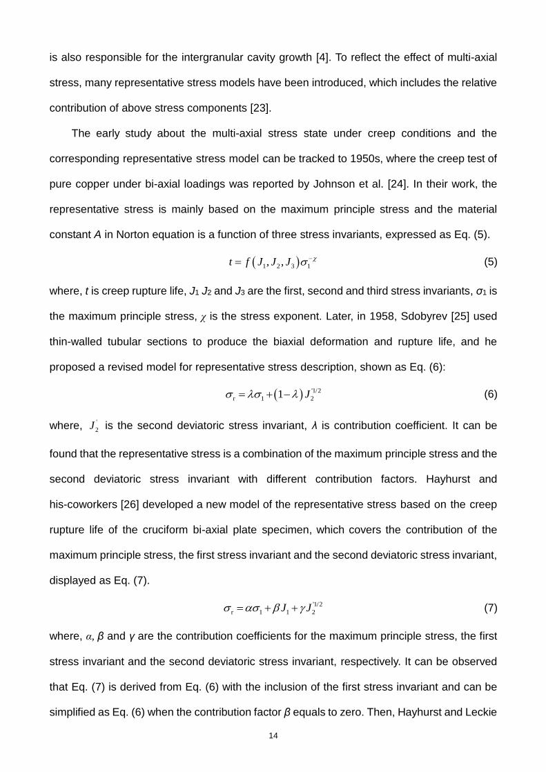
The early study about the multi-axial stress state under creep conditions and the
corresponding representative stress model can be tracked to 1950s, where the creep test of
pure copper under bi-axial loadings was reported by Johnson et al. [24]. In their work, the
representative stress is mainly based on the maximum principle stress and the material
constant A in Norton equation is a function of three stress invariants, expressed as Eq. (5).
1 2 3 1, ,t f J J J (5)
where, t is creep rupture life, J1 J2 and J3 are the first, second and third stress invariants, σ1 is
the maximum principle stress, χ is the stress exponent. Later, in 1958, Sdobyrev [25] used
thin-walled tubular sections to produce the biaxial deformation and rupture life, and he
proposed a revised model for representative stress description, shown as Eq. (6):
'1/2
r 1 21 J (6)
where, '
2J is the second deviatoric stress invariant, λ is contribution coefficient. It can be
found that the representative stress is a combination of the maximum principle stress and the
second deviatoric stress invariant with different contribution factors. Hayhurst and
his-coworkers [26] developed a new model of the representative stress based on the creep
rupture life of the cruciform bi-axial plate specimen, which covers the contribution of the
maximum principle stress, the first stress invariant and the second deviatoric stress invariant,
displayed as Eq. (7).
'1/2
r 1 1 2J J (7)
where, α, β and γ are the contribution coefficients for the maximum principle stress, the first
stress invariant and the second deviatoric stress invariant, respectively. It can be observed
that Eq. (7) is derived from Eq. (6) with the inclusion of the first stress invariant and can be
simplified as Eq. (6) when the contribution factor β equals to zero. Then, Hayhurst and Leckie

15
[27] found that the maximum principal stress and the effective stress are much more
important than the hydrostatic stress in determining multi-axial creep rupture. Thus, the
contribution coefficient β in Eq. (7) is assumed as zero and the second deviatoric stress
invariant is transformed as equivalent stress. Then, the above representative stress (Eq. (7))
is modified as Eq. (8):
r 1 e1 (8)
where, σe is the equivalent stress. Later, Cane [28] discussed the mechanism of the formation
and growth of cavities and it was found that the controlling factors are mainly attributed to the
maximum principle stress, and the ratio between the maximum principle stress and the
equivalent stress. Then, a model for representative stress was provided, shown as Eq. (9).
1
r 1 e
pp
(9)
where, p is the contribution coefficient for maximum principle stress. Also, Huddleston [29]
provided an improved multi-axial creep strength criterion based on the further development
of the work of Cane [28], which incorporates three independent stress parameters, shown as
Eq. (10).
1r 1
1
23exp 1
2 3
a
e
s
JS b
S S
(10)
where, S1 is the maximum deviatoric stress, J1 is the sum of three principle stresses, Ss is an
invariant stress parameter, a and b are material constants. The bi-axial creep data of 304SS
at 593℃ are taken for the validation of the proposed criteria. It should be noted that this
model has been adopted by the ASME III-NH standard for creep damage evaluations based
on the inelastic analysis with a slight modification (suppose parameter a=1.0). As a whole,
the above models are mainly limited to creep rupture life of the specimens under bi-axial
stress states (e.g. cruciform biaxial plates or thin-walled tubes with torsion loadings), while
the complex tri-axial stress state around the notch root of the bars are not included. The
main differences of two stress states (e.g. bi-axial plates and tri-axial notched bars) are as
16
follows: For notched bars, the stress state around the notch root or across the notch plane is
not uniformly distributed, which is quite different from that of the cruciform bi-axial plates,
which have the same stress state for any node at the specimens. Therefore, the
representative stress model reported for specimens subjected to bi-axial stress state is likely
not adequate to describe the tri-axial stress state (e.g. the stress state around the root of
notched bars).
With the further development of the representative stress model, the tri-axial creep
rupture data (e.g. notched bars) are mentioned to formulate a more general description. For
example, Nix et al [4] proposed a modified formulation of the representative stress, shown as
Eq. (11), which is based on the stress redistribution associated with grain boundary sliding
and is expected to be valid for alloys that exhibit grain boundary sliding and fail by cavitation
of grain boundaries perpendicular to the maximum principal stress.
r 1 2 32.24 0.62 (11)
where, σ2 and σ3 are the second and third principle stresses, respectively. This model has
been validated by the creep data of cruciform biaxial plates and notched bars reported by
Hayhurst et al. [3], Cane [30], Stanzl et al. [31], Dyson and Mclean [32], and so on. It should
be noted that the stress adopted for evaluations for are mainly based on the node at the
center of the notch plane. Further investigations by Kraus [33] presented that for symmetric
shapes and simple loading conditions (e.g. constant tension, pressure or bending), a point
exists in the cross-section of the notch plane where the stress remains unchanged during
the creep process. Al-Faddagh et al. [34] conducted some numerical studies on the creep
behavior of the notched bars and also reported that the there is a region with approximately
constant effective stress, which is also independent of the stress index n. Moreover, an
approximate method was established for estimating the maximum equivalent steady-state
stress across the notch throat. Similar works are also made by Hayhurst and his co-workers
[35]. With the further development of the skeletal point stress, the skeletal point stress for a
17
variety of notch geometries have been analyzed and a code of practice for notched bar
testing was formulated initially in 1991 [36] and updated in 2004 [23]. Based on the standard
established, many experimental results are conducted to demonstrate the applicability of the
representative stress at the skeletal point and good consistency is also observed. For
example, Goyal et al. [5, 17, 19] conducted the creep tests of the notched bars made of
9Cr-1Mo steel and 2.25Cr-1Mo steel at high temperatures. The observed creep rupture data
are employed to characterize the multi-axial creep life based on the skeletal point concept
(see Fig. 8) and three representative stress models are included for analyses, such as the
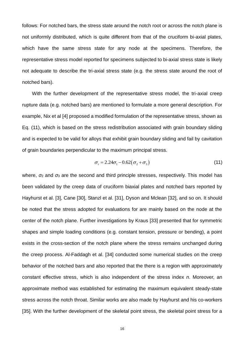
model of Hayhurst et al. [26], Cane [30] and Nix et al. [4], all indicating an adequate solution.
Fig. 6 Normalized effective stress distribution at steady state across the throat of a
semi-circular notch [23]
The above description mainly includes the evolution behavior of the representative
stress, and the skeletal point concept is also mentioned for analyses. Based on the above
equation describing the representative stress, the characteristic equivalent stress of the
notched component can be found. Then, the creep rupture life of the notched component
can be calculated and the notch effect on creep rupture life of the component can be

18
evaluated. Taking the equation by Hayhurst et al as an example, the maximum principle
stress and the equivalent stress at the skeletal point can be determined. Then, the
representative stress of the component can be gained using the material parameter. At this
time, if the representative stress is higher than the average stress for the smooth specimen,
then the weakening effect is prone to happen. Otherwise, the strengthening effect can occur
if the representative stress is smaller than the average stress for the smooth specimen.
3.2.2 Methods based on continuum damage mechanics (CDM)
Yao et al. [37] reviewed the creep analysis and design methods for components under
multi-axial stress states. Meanwhile, they divided the existing theories and creep design
approaches into three categories, including the classical plastic theory (CPT) based
approach, the cavity growth mechanism (CGM) based approach and the continuum damage
mechanics (CDM) based approach. For CDM-based damage models, in general, these
models mainly originate from the work of Kachnaov [38], Rabotnov [39], Lemaitre [40] and
so on. It should be noted that the representative stress concept mentioned in Section 3.2.1
can also be coupled with CDM analysis, such as the work of Hayhurst et al. [3], Hyde et al.
[10, 11], Liu and Murakami [41], Jiang et al. [42, 43], Goyal et al. [5, 17, 19] , Zhang et al. [44],
and so on. Numerical results presented that the critical creep damage of the notched
component is highly related to the notch shapes, stress levels, et al. Exactly speaking, for a
relatively shallow notch, the critical creep damage is located at the zone inside the notch tip,
while it is nearly around the notch root for a relatively sharp notch. Moreover, the predicted
creep rupture lives of the notched components are also consistent with the experimental
results, but the specific solution accuracy is dependent on the material studied. For example,
the error band of the predicted creep rupture life of the notched component is within a factor
of 1.1 for GH3536 [44] and it is 3.0 for 9Cr-1Mo steel [5, 17].
The above mentioned damage constitutive equations are mainly limited to stress-based
damage models. The main disadvantage of these models is that many material equations

19
are introduced in these damage models, and great efforts should be made to the
determination of these parameters, causing a big barrier for engineering applications of the
above models. Based on this, the strain-based damage model (e.g. ductility exhaustion
concept) has been included for creep damage evolution analysis of the components at
elevated temperatures due to the simplicity of the model with fewer material parameters,
which was adopted since the work of Yatomi et al. [45, 46]. Recently, similar work about the
notch effect on creep rupture life of the component was also conducted by Xu et al. [20],
where the Cock-Ashby model was also employed to describe the relationship between the
uniaxial creep fracture strain and multi-axial creep fracture strain. It was concluded that for
creep ductile materials, the creep rupture life of the notched component is determined by the
combining action of the equivalent stress and stress tri-axiality. At the beginning of the creep
process, the equivalent stress presents a remarkable stress relaxation, and the
corresponding stress tri-axiality is higher than that of the smooth specimen. Meanwhile, with
the further increase of creep process, the equivalent stress remains a low stress level and
the equivalent stress plays an important role on creep strain rate or creep damage rate of the
notched component. This is why the creep strain rate (i.e. creep damage rate) is smaller
than that for the smooth specimen. Numerical results may present strengthening and
weakening effects for various geometrical, material types, loading conditions, and so on.
Meanwhile, the critical creep damage is mainly located at the zone inside the notch root for
creep ductile material, which is consistent with the experimental results provided in Fig. 5.
3.2.3 Analytical methods
Some analytical equations between the effective stress and the geometrical parameters,
as well as the correlation of the creep rupture life and the notch parameter, are mentioned.
For example, Dyson and Loveday [47] conducted notched specimens of Nimonic 80A with a
Bridgman geometry at 750℃ using a wide stress range (154-600MPa). The strengthening
behavior was clearly observed and the Bridgman effective stress [48] was taken as the

20
representative stress, shown as Eq. (12). This method was also considered for a qualitative
comparison in Ref. [22].
1
eff net net
21 ln 1
2 2
R a af
a R R
(12)
where, σeff is the effective stress, σnet is the net section stress, a is the distance from the
center of the specimen to the notch root and R is defined as the radius of the notch. It should
be stated that this analytical equation can only be adopted to analyze the strengthening
effects and this is because the factor 2
af
R
in Eq. (12) has a value smaller than 1.0, shown
as Fig. 7. When the weakening effects of the notched components are reported, the above
analytical strategy is no longer available.
0 5 10 15 20 25 30 350.0
0.2
0.4
0.6
0.8
1.0
eff
=net
* f(a/2R)
f(a/2R)
Fa
cto
r f(
a/2
R)
Notch acuity ratio (a/2R)
1
Fig. 7 Relationship between the factor f(a/2R) for Bridgman effective stress and notch acuity
ratio of notched components
4 Notch effect of components under fatigue loadings
4.1 Notch effect and related factors
In general, the experimental studies on the notched components under fatigue loadings

21
are mainly divided into two controlled modes: stress-controlled and strain-controlled modes.
In following, the notch effect of the components under these two controlled modes will be
provided.
4.1.1 Stress-controlled mode
For stress-controlled mode, notch effects of the components under low cycle fatigue
loadings at elevated temperatures have been discussed [49-62]. Among these cases studies,
many kinds of specimens are taken for analyses, such as notched bar specimens,
single-edge or double-edge notched plates, plate component with a hole, and so on. It is
always assumed that the net section stress of the notched component is the same as that of
a smooth specimen. Through experimental investigations reported, in general, the notched
component has a shorter cycle to failure than a smooth component, meaning that the notch
has a weakening effect (see Fig. 8). Meanwhile, it is found that the weakening effect is much
more remarkable for specimens with a high stress concentration factor (SCF) than that with a
small SCF. The main reason for the weakening effect is that the surface crack is easily
initiated at the notch root of the notched components due to a high local stress/strain at the
notch root. With the development of the optical technology, it makes in situ viewing of the
fatigue crack initiation possible by taking a telephoto lens microscope combined with a video
camera [49, 51, 63]. Experimental results demonstrate that fatigue crack is initiated around
the notch root for the notched plates and bars, or at the edge of the hole for plates with a
hole, further supporting the above understandings.
The effect of the stress level on notch effect on cycle to failure of the component is also
shown in Fig. 8. It should be noted that the detailed stress levels are not marked in the figure,
but they are all based on a certain specimen (corresponding to a stress concentration factor),
implying they have the same horizontal axis for a given specimen made of a certain material
in Fig. 8. It can be found that the extent of the notch weakening effect is closely related to the
stress level applied. Similar conclusion about the effect of the temperature on notch effect

22
can be obtained based on the experimental results in Ref. [52]. It should be noted that these
two factors usually do not alter the notch effect on cycle to failure of the component from
weakening effect to strengthening effect.
1 2 3 4 5 61E-4
1E-3
0.01
0.1
1
Notched plates:
FGH97 (550℃ )[63]
DZ125 (850℃ )[61,71]
40CrMoV13.9 (650℃ ) [64]
Plate with a hole:
DZ125 (850℃ )[71]
304SS (600℃ )[74]
No
tch
effe
ct co
effic
ien
t
Stress concentration factor (SCF)
Fig. 8 Notch effect of high temperature components under stress-controlled fatigue loadings
In addition, the effect of the stress ratio on notch effect may be different from that of the
stress level and temperature, which may alter the notch effect from weakening effect to the
strengthening effect with the increasing stress ratio. This is mainly because with the increase
of the stress ratio, a relatively large average stress may induce an evident creep contribution
during the cyclic process according to the numerical results obtained in Ref. [1]. Thus, the
strengthening effect caused by the notch can probably be detected for fatigue loadings with
a high stress ratio. It should be noted that the above description is only limited to notched
bars (with a hoop notch) or single-edge/double-edge notched plates, while the plates with a
hole do not present such behavior. This is mainly because the hole causes a weakening
effect even under pure creep conditions and the stress ratio does not cause the change from

23
notch weakening effect to notch strengthening effect.
4.1.2 Strain-controlled mode
For strain-controlled mode, notch effects of the components under low cycle fatigue
loadings at elevated temperatures have been discussed [63, 64]. It is always assumed that
the applied strain imposed to a notched specimen is the same as that to a smooth component
for strain controlled mode, which is different from the assumption for stress-controlled mode.
Under this circumstance, it can be expected that the local stress and strain around the notch
root is much higher than the applied strain (equals to that for smooth specimens).
Experimental investigations also indicate that the notched component has a shorter cycle to
failure than a smooth component, implying a weakening effect (see Fig. 9). Moreover,
components with a higher SCF can induce a more remarkable reduction of fatigue strength.
Similar to that under stress-controlled mode, the main cause for the weakening effect is that
the surface crack is easily initiated at the notch root due to a high local stress/strain at these
zones. For plate specimens with a hole, the experimental results under strain controlled
mode are relatively rarely reported. Even so, it can be expected that the hole present a
weakening effect due to the prominent stress and strain concentration around the edge of
the hole.
As reported in Section 4.1.1, it is stated that for a relatively high stress ratio, the notch
may indicate a strengthening effect under fatigue loadings. However, this phenomenon is
difficult to occur for component under strain-controlled mode. The current experimental study
about the strain-controlled mode is mainly based on the assumption that the applied strain
for smooth and notched specimens is the same, equivalent to the same external loadings.
With the increase of the stress ratio, the creep contribution caused by the average stress
gets remarkable. However, the notched and smooth components still sustain the same
external loadings and the weakening effect can be gained even under pure creep conditions,
which is quite different from the conclusion for stress-controlled mode in Section 4.1.1.

24
4.2 Related models for notch effect on fatigue strength of components
4.2.1 Methods for applications at room temperature
In current studies, the notch effect has been included when conducting the multi-axial
fatigue strength evaluation of the notched component, especially at room temperature. Many
methods have been proposed for multi-axial fatigue strength representation by researchers.
In general, the current methods can be divided into several classes: (1) One is the classical
method aiming to establish the description of the effective stress of the notched component.
The typical approaches are listed below: local stress/strain approach (LSSA), stress gradient
approach (SGA), normal stress approach (NSA), stress field intensity approach (SFIA) [65],
critical distance approach (CDA) [66, 67], critical plane approach (CPA) [68], critical volume
approach (CVA) [69], and so on. (2) The second is to evaluate the fatigue life of the notched
component by the strain-based variables, such as the equivalent strain range, maximum
principle strain, maximum shear strain, and so on. (3) The third is based on energy approach
(EA) [70]. Among these methods, some have been successfully adopted for the fatigue life
evaluation of the notched component, and even engineering structures, indicating a
reasonable prediction solution.
4.2.2 Methods for applications at high temperature
For notched components at elevated temperature, the notch effect representation has
been discussed by some researchers when investigating the notch effect made of various
materials. As a whole, many experimental results have demonstrated that multiply cracks
initiate at the surface of the notch. Meanwhile, the process of the fatigue crack initiation and
propagation can be real-time recorded. Researchers come to conclude that the location of
the fatigue crack initiation is some distance away from the notch root. For example, Moore et
al. [61, 71] discussed the notch fatigue behavior of the directionally solidified (DS) superalloy
CM247LC at 750℃ and 950℃. It was concluded that the crack initiation is not located at the
notch root, which is consistent with the maximum Hill’s stress. Later, Shi et al. [49] discussed

25
the effect of notch types and stress concentration factor on low cycle fatigue life and
cracking of DS superalloy DZ125. It was also found that the cracking does not occur at the
notch apex but at the location where the maximum principal stress or Hill’s stress is the
highest. Similar results are also reported in Refs. [51, 53, 63], and isotropic materials (e.g.
304SS in Ref. [63]) are also mentioned. In addition, for the thermomechanical fatigue
behavior, it was also reported that the fatigue crack offsets from the notch root [72, 73]. It
should be noted that for the fatigue crack propagation, in general, the fatigue crack turned to
the plane perpendicular to the loading direction. Meanwhile, as reported in Ref. [49], the
fatigue crack path is dependent on the stress concentration factor: it presents a zigzag line
for components with a small SCF, while the straight crack propagation can be detected for a
high stress concentration factor.
To accurately predict the fatigue life of the notched component, several models have
been proposed. For instance, Domas and Antolovich [74] provided an approach to predict
the fatigue life of the notched component based on hysteresis loop energy. Many fatigue
data were adopted to validate the proposed model, but results presented that limited data
can be correlated correctly. Leidermark et al. [75] discussed the fatigue life of the
components in presence of notches using a critical plane approach combined with a critical
distance concept and it seemed that the simulated results are consistent with the
experimental results. Berto et al. [52] studied the stress-controlled fatigue tests on smooth
and notched specimens made of 40CrMoV13.9 steel. Meanwhile, fatigue data from
un-notched and notched specimens are re-analyzed by means of the mean value of the
strain energy density (SED), presenting a reasonable solution. Also, stress relaxation locus
(SRL) method is taken for the prediction of the strain range and the cycle number, and it is
concluded that the SRL method with a coefficient of 1.6 can provide a reasonable prediction
[63, 64]. Based on the stress-strain behavior of the material in the notch, Filippini [53]
proposed a fatigue damage parameter (the maximum range of resolved shear stress on the

26
crystallographic planes), which allows the transferability of tests results from plain specimen
data to notched specimen data. Later, Huang et al. [59] developed a simple unified critical
plane damage parameter (i.e., the modified resolved shear strain range) based on a slip
mechanism-related critical plane concept, where the critical plane is determined as the slip
plane on which the damage parameter is the maximum during the cycle. The predicted
results also demonstrated that the proposed critical plane damage parameter can provide a
reasonable solution, where the material orientation, temperature, loading ratio and notch
shapes are also included. In addition, Karolczuk and Macha [76] reviewed the multiaxial
fatigue failure criteria based on the critical plane concept, which are divided into three groups
(i.e. (i) stress, (ii) strain and (iii) strain energy density criteria), according to the fatigue
damage parameter used in the criterion. As a whole, the above models have been
successfully employed for the life prediction of the notched components (at lease for cases
studied), but the applicability of these models to other cases or materials still needs more
investigations. Therefore, a generalized life prediction model under multi-axial fatigue
loadings is necessary and crucial. Moreover, the solution of the model is another challenge
for a reasonable description of the notched components under cyclic loadings.
5 Notch effect of components under creep-fatigue loadings
Considering that the notch effects on notched components under creep-fatigue loading
conditions with stress and strain controlled modes are different from each other, so in
following, the stress and strain-controlled modes are discussed separately.
5.1 Stress-controlled mode
In previous studies, creep-fatigue tests of notched components under stress-controlled
creep-fatigue loading conditions have been reported [22, 60, 77-80], where the strengthening
and weakening effects are both mentioned. As a whole, the notch effect is closely related to
material ductility (ductile or brittle materials), loading parameters, and so on.

27
5.1.1 Ductile materials
For ductile materials, as described in Sections 3 and 4, some consistent conclusions
about notch effect have been drawn for components under creep conditions or fatigue
loadings only. Taking the notched bar specimens with a circumferential C/U/V-shape notch for
example, the notch usually presents a strengthening effect under creep conditions only, but it
indicates a weakening effect for notched structures under fatigue loadings only. For notch
effect under creep-fatigue loading conditions, however, the notch strengthening and
weakening effects are both reported, such as the work of Sakane et al. [77], where they
analyzed the frequency and hold-time effects on stress-controlled low cycle fatigue for
notched bar specimens made of SS304. Further investigations about their experimental
results (see Fig. 9) demonstrate that the notch effect is closely related to holding time. The
weakening effect is observed for a small holding time (e.g. 0.0056h), while it changes to
strengthening effect when the holding time is long enough (e.g. 0.27h and 2.77h). The above
phenomenon can also be explained by Fig. 10. When the holding time is zero, the
creep-fatigue loading is just fatigue loading and the notch presents a weakening effect, while
it changes to the creep spectrum with an infinite long holding time, and the notch
strengthening effect is observed. For creep-fatigue conditions, however, the notch effect is
dependent on the holding time and it is concluded that the difference could be ascribed to the
creep damage contribution in the holding stage [1]. Meanwhile, the stress concentration
factor (SCF), stress ratio, and the maximum stress are all included in Ref. [1] and the results
indicated that the influences of the above factors are strongly dependent on the competition
of creep and fatigue mechanism.
As described in Section 3, it is found that the critical creep damage is located at the place
inside the notch tip for components with a relatively shallow notch, while the fatigue crack can
be more easily formed at the notch root. Thus, for the creep-fatigue loadings, the maximum
damage should be located at the zone between the two above critical locations. Recently,

28
experimental investigations in Ref. [22] displayed that the primary initiation site is internal at a
substantial distance away from the notch root for the air and vacuum tested cyclic max dwell
fatigue tests, as shown in Fig. 11. The location of the primary failure origin away from the
notch root is attributed to visco-plastic stress redistribution controlling the damage evolution
process. Meanwhile, a single small secondary surface initiation region was also found for
cases mentioned (see Fig. 11). Similar experimental results are also observed in Ref. [6],
where the experimental studies on the notched bar specimens of a low alloy steel are
conducted. In their work, the SEM results of the notched bar specimens after fracture
manifested that micro damages (e.g. small creep cracks) are mainly observed around
several hundred micro-meters below the surface.
It should be noted that the above conclusions are mainly limited to notched components
with a hoop notch, and may be applied to single-edge or double-edge plates. For plate
specimens with a hole, limited experimental studies under stress-controlled creep-fatigue
loading conditions are reported [60]. In general, as concluded in Sections 3 and 4, the hole
indicates a weakening effect for creep conditions for ductile materials, and also presents a
weakening effect when fatigue loading conditions are considered. Thus, it can be expected
that the hole always presents a weakening effect for creep-fatigue loading conditions (see
Fig. 10). The experimental results in Ref. [60] also support this point, where the plate with a
hole made of DZ125 superalloy at 850℃ under creep-fatigue loading conditions is tested.
5.1.2 Brittle materials
For notched components made of brittle materials, related works are rarely published.
When creep conditions (one extreme condition of creep-fatigue loadings) are considered only,
the notch usually presents a weakening effect. This is because the stress re-distribution of
the notched component is relatively slow and the local accumulated strain exceeds the limit
required for fracture before attaining the stationary state across the notch throat plane [5, 17,
19]. The numerical results of Ref. [20] also support that the weakening effect can be detected

29
for material with relatively small creep ductility. For the other extreme condition, fatigue
loadings, the crack initiation is easier at the notch root and the crack propagation rate is faster,
and then a notch weakening effect is expected. For cases under creep-fatigue loadings,
considering that the creep conditions and fatigue loadings are two extreme cases of
creep-fatigue loadings, it can be expected that a notch still presents a weakening effect by
analogy to ductile materials shown in Fig. 10. Surely, further experimental validation for the
notch effect evaluation is also needed for an intuitive demonstration.
0.0 0.5 1.0 1.5 2.0 2.5 3.00.0
0.5
1.0
1.5
2.0
2.5
Co
effic
ien
t fo
r n
otc
h e
ffe
ct
Holding time (h)
Kt=1.0 Kt=2.6
Kt=4.2 Kt=6.0
weakening
strengthening
Fig. 9 Weakening and strengthening behavior of notches under the creep–fatigue
condition in terms of the of Ref. [77] ([1])

30
Fig. 10 Schematic diagram of notch effect under creep/fatigue/creep-fatigue conditions [1]
Fig. 11 Comparison of failure modes and dwell fatigue lives for air and vacuum tested cyclic
max dwell notch low cycle fatigue specimens tested at 793 MPa [22]
It should be noted that the current work about the notch effect under stress-controlled
mode is mainly limited to tensile holding time only, while the compressive holding time is
rarely considered. Some experimental studies have focused on the creep-fatigue behavior of
the notched components. For example, Telesman et al. conducted the study about the effect
of notches on creep-fatigue behavior of a P/M nickel-based superalloy, and the results
presented that the compressive holding time can cause an even more detrimental effect on
creep-fatigue strength of components than that with a tensile holding time. In general, it is
thought that the compressive holding time can induce a closure effect of the crack and then
prevent the rate of the crack propagation. The conclusion obtained is quite different from the
general understanding of the effect caused by the compressive holding time. The mechanism

31
of the above phenomenon is ascribed to the remarkable oxidation behavior during the
compressive holding stage. Considering that the link between the oxidation behavior and
mechanics-based variables is quite complex and is not clearly established, it is not easy to
discuss the representation of notch effect currently and much work is still needed for future
studies.
5.2 Strain-controlled mode
For notched bar specimens, strain-controlled creep-fatigue experimental studies on the
notched bar components are reported [71, 81-86]. For stress-controlled mode mentioned
above, the uniform stress at the notch plane is kept as the same as that of the smooth
specimens. Different from that for stress-controlled mode, the application of the strain can be
divided into two methods (see Fig. 12): The first method is to directly apply the same strain for
a notched component as that for a smooth specimen (see Fig. 12a). At this moment, the
strain at the notch root for a notched component is higher than that for a smooth specimen.
References [81, 82] have demonstrated that the notch weakening effect is clearly observed
for the cases mentioned. Moreover, in general, the notch weakening effect is more
remarkable for a large stress concentration factor than that for a small stress concentration
factor (see Fig. 13). The opposite behavior is also found by Nozaki et al. (see Fig. 13), but
the possible reason may be due to the limited specimens conducted in their experimental
studies. The second method is to keep the maximum strain around the notch root as a
constant for components with various elastic stress concentration factors (see Fig. 12b), and
the applied strain can be determined by detailed finite element analysis. Experimental results
of Refs. [83-85] have displayed that the notch presents a strengthening effect and the
strengthening effect is more remarkable with the increasing elastic stress concentration
factor (see Fig. 13).

32
(a) Notch effect for the same loadings (b) Notch effect for the same strain
Fig. 12 Two possible conditions for notch effect of notched components under creep-fatigue
loading conditions
0 20 40 60 801E-3
0.01
0.1
1
10
100
weakening
Kt2.6
4.2
6.0
Sakane (1983, Kt=2.6)
Sakane (1983, Kt=4.0)
Sakane (1983, Kt=6.0)
Nozaki (2011)
Ando (2014)
Co
effic
ien
t fo
r n
otc
h e
ffe
ct
Holding time (min)
Kt=2.85
Kt=1.36strengthening
Fig. 13 Weakening and strengthening behavior of notches under the strain-controlled
creep–fatigue condition in terms of Refs. [81-83]
For plate specimens with a hole, the experimental tests are usually based on the
loading condition of Fig. 12a. As mentioned in Section 5.1, the hole usually indicates a
weakening effect for ductile or brittle materials due to the remarkable stress/strain
concentration around the hole. This rule is also applicable to specimens with a hole under
strain controlled creep-fatigue loading conditions. This is because the stress around the hole

33
can approach to the uniform stress state for a smooth specimen due to the remarkable
stress relaxation around the hole during the holding stage, but it is still higher than that for a
smooth specimen. Therefore, it can be expected that the weakening effect can be observed
for specimens with a hole subjected to creep-fatigue loading conditions. In addition, there
are other experimental studies over the creep-fatigue behavior of the notched component
under strain controlled creep-fatigue loading conditions [64, 87-89]. However, the
experimental results of the notched components are only provided and that of the smooth
specimens are not reported, so it is difficult to conduct a notch effect evaluation.
5.3 Notch effect evaluation under creep-fatigue loading conditions
To evaluate the notch effect of the notched components under creep-fatigue loading
conditions, the allowable cycles to failure for smooth and notched specimens should be
identified, meaning that the evaluation procedure for creep and fatigue damage should be
chosen firstly. There are several methods for notch effect study of the components under
creep-fatigue loadings, such as the procedures in some international standards (e.g. ASME
III-NH [90], R5 [91]), the revised procedure based on ASME III-NH [1], and so on.
5.3.1 Main evaluation procedures
Some international standards have provided the creep and fatigue damage evaluation
procedures for components under creep-fatigue loadings, such as ASME III-NH, R5, and so
on. These standards are based on the time fraction model, but the creep damage evaluation
procedures recommended in these standards have some remarkable differences. Exactly
speaking, in ASME III-NH, the creep damage is defined as the ratio of the holding time to the
allowable creep rupture life, which is evaluated by the effective stress for inelastic analysis
(see Eq. (13)). In addition, fatigue damage is evaluated by the maximum equivalent strain
range (see Eq. (14)).
1 2 3eff vm 1/2
2 2 2
1 2 3
exp 1C
(13)
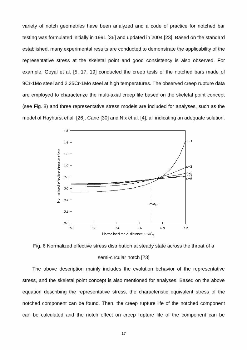
34
1/2
2 2 2 2 2 2
equiv, *
2 3
22 1i xi yi yi zi zi zi xyi yzi zxi
(14)
where, σeff is the effective stress; σvm is the equivalent von Mises stress; C is a material
constant; Δεequiv,i is the equivalent von Mises strain range for time point i; Δεxi, Δεyi, Δεzi, Δ
γxyi, Δγyzi, Δγxzi are the corresponding differences of the six strain variables for each point in
time i; ν* is the Poisson’s ratio and equals to 0.5 for inelastic analysis. However, in R5
standard, the creep damage is based on the ductility exhaustion concept, shown as Eq. (15)
0
0f
dt
cD t
(15)
where, is the strain rate for a certain moment; f is the creep ductility for a certain stress
state, which can be identified by Cock-Ashby, or other models, transforming the multi-axial
creep ductility to uniaxial ones. Based on the creep and fatigue damage per cycle, as well as
the damage evaluation criteria, one can determine the allowable cycles to failure (Nnotch and
Nsmooth) of the notched and smooth components, marked as the life of the notched and
smooth specimens. Then, the notch effect can be identified using the ratio of the two.
Besides, Gong and Xuan [1] proposed another damage evaluation procedure when
conducting the notch effect analysis of the notched bar specimens based on the procedure
of ASME III-NH, where the creep damage is evaluated by the representative stress at the
skeletal point but the fatigue damage is still based on the maximum equivalent strain range.
5.3.2 Applications for notch effect evaluation
For notched components with a circumferential notch, the procedure in ASME III-NH has
been adopted for notch effect analysis [1]. Numerical results demonstrated that the current
creep damage evaluation cannot describe the strengthening effect for notched component
under creep conditions. Based on the existing problem, Gong and Xuan [1] proposed a
revised method for creep damage evaluation based on the Hayhurst’s representative stress
of skeletal point instead of the effective stress in ASME III-NH, and the fatigue damage is still
35
based on the equivalent strain described in ASME III-NH. Results presented that the revised
method is adequate to discuss the notch effect for components under creep-fatigue
conditions. The notch presents a weakening effect for a small holding time, while it displays a
strengthening effect for a long holding time. These conclusions are consistent with the
experimental results in Ref. [77]. It should be noted that the above description is mainly
focused on the bar specimens with a hoop notch. When the single-edge or double-edge plate
specimens are mentioned, it is expected that they present a similar notch effect behavior to
bar specimens with a hoop notch.
For components with a hole, the damage behavior is quite different from that of the
notched components with a hoop notch. Therefore, how to discuss the creep and fatigue
damage is a main challenge. For creep damage, continuum damage mechanics (CDM)
method has been adopted to identify the damage behavior during the whole creep process
[21]. Results presented that the maximum creep damage is always located at the corner
angle perpendicular to the loading axis, which is also higher than the damage for the smooth
specimen. This indicates that the notch or the hole has a weakening effect on the structural
strength of the component. For fatigue damage, it is also based on the maximum equivalent
strain range in ASME III-NH and the weakening effect is observed, consistent with general
conclusions in Section 3. As a whole, the weakening effect can be expected for specimens
with a hole under creep-fatigue conditions.
It should be stated that although the above methods could provide a basic notch effect
analysis, the notch effect factor calculated is not very consistent with the experimental results.
Thus, further analyses on notch effect evaluation are still needed, including the creep and
fatigue damage evaluation procedures. Moreover, the creep-fatigue interaction may
introduce difficulties for exact evaluation and should be mentioned in future investigations.

36
6 Concluding remarks
This work mainly reviews the experimental and numerical studies on notch effect of high
temperature components under creep, fatigue and creep-fatigue loading conditions. Some
progresses have been achieved over the notch effect analysis and evaluation for notched
components under the above loading conditions. The strengthening and weakening effects
are both observed for components under creep conditions, which are related to the notch
shape, material ductility, stress level, and so on. For specimens subjected to fatigue loadings,
the weakening effect is mainly found due to the remarkable stress/strain concentration
around the notch root or the hole. When the creep-fatigue loading conditions are mentioned,
the notch effect is dependent on the controlling mode, material ductility, notch shape, and so
on. As a whole, the complex mechanisms of the notch effect have been stated for
components under creep, fatigue and creep-fatigue loading conditions, which are also
consistent with experimental results. It should be noted that there are still some questions
needing further investigations, which are listed below:
(1) The notched component is a basic structural component for further investigating the
engineering components under complex loading conditions. The current notch strengthening
and weakening effects have been reported and analyzed, but only some of these
conclusions can be applicable to engineering components. This is because it is difficult to
define the similar reference cross-section to the notched component, and accordingly the
methods developed by notched components could not be employed directly for engineering
cases. In the future, a general method is still needed for the accurate description of the
failure life of the practical components. Surely, the importance of the notched component
could not be replaced due to its simple geometry and they are important structural cases for
experimental validations.
(2) Although the procedure for notch effect analysis has been established for notched
component under creep, fatigue and creep-fatigue loading conditions, the notch effect

37
coefficient is still not very consistent with the experimental results. This means that the
current creep/fatigue damage evaluation procedures may not evaluate the corresponding
damage exactly. Thus, much attention should be paid to the improvement and development
of the current life evaluations of the notched components.
(3) For creep-fatigue loading conditions, notch effect is closely related to material
ductility, loadings parameters, geometrical parameters, etc. Among these factors, various
materials and geometrical parameters are included, but the creep-fatigue loading
parameters are mainly limited to tensile holding time only. Further investigations on notched
components under creep-fatigue conditions are still needed to discover the notch effect with
compressive holding stage included.
Acknowledgment
Supports from National Science Foundation of China (51605165, 51475167), National
Key Research and Development Program of China (2016YFC0801905), and the ‘111 project’
are greatly acknowledged.
References
[1] Gong JG, Xuan FZ. Notch behavior of components under the stress controlled
creep-fatigue condition: Weakening or strengthening? Journal of Pressure Vessel
Technology-Transactions of the Asme. 2017; 139(1): 011407.
[2] Gong JG, Xia QW, Xuan FZ. Evaluation of Simplified Creep Design Methods Based on the
Case Analysis of Tee Joint at Elevated Temperature. Journal of Pressure Vessel
Technology-Transactions of the Asme. 2017; 139(4): 041412.
[3] Hayhurst DR, Dimmer PR, Morrison CJ. Development of continuum damage in the creep
rupture of notched bars. Philosophical Transactions of the Royal Society of London A
(Mathematical and Physical Sciences). 1984; 311(1516): 103-29.
38
[4] Nix WD, Earthman JC, Eggeler G, Ilschner B. The principal facet stress as a parameter for
predicting creep rupture under multiaxial stresses. Acta Metallurgica. 1989; 37(4):
1067-77.
[5] Goyal S, Laha K, Das CR, Panneerselvi S, Mathew MD. Effect of Constraint on Creep
Behavior of 9Cr-1Mo Steel. Metallurgical and Materials Transactions A. 2014; 45A(2):
619-32.
[6] Isobe N, Yashirodai K, Murata K. Creep damage assessment for notched bar specimens
of a low alloy steel considering stress multiaxiality. Engineering Fracture Mechanics. 2014;
123: 211-22.
[7] Yu QM, Wang YL, Wen ZX, Yue ZF. Notch effect and its mechanism during creep rupture
of nickel-base single crystal superalloys. Materials Science and Engineering A. 2009;
520(1-2): 1-10.
[8] Lukas P, Preclik P, Cadek J. Notch effects on creep behaviour of CMSX-4 superalloy
single crystals. Materials Science and Engineering A. 2001; 298(1-2): 84-9.
[9] Liu DS, Wen ZX, Yue ZF. Creep damage mechanism and gamma'-phase morphology of a
V-notched round bar in Ni-based single crystal superalloys. Materials Science and
Engineering A. 2014; 605: 215-21.
[10] Hyde TH, Becker AA, Song Y, Sun W. Failure estimation of TIG butt-welded Inco718
sheets at 620 degrees C under creep and plasticity conditions. Computational Materials
Science. 2006; 35(1): 35-41.
[11] Hyde TH, Xia L, Becker AA. Prediction of creep failure in aeroengine materials under
multi-axial stress states. International Journal of Mechanical Sciences. 1996; 38(4):
385-401.
[12] Konish HJ. Simplified Estimation of Creep-Rupture Strength for Notched Tensile
Specimens of Austenitic Stainless Steels. Journal of Pressure Vessel
Technology-Transactions of the Asme. 1988; 110(3): 314-21.

39
[13] Ganesan V, Kumar JG, Laha K, Mathew MD. Notch creep rupture strength of 316LN SS
and its variation with nitrogen content. Nuclear Engineering and Design. 2013; 254:
179-84.
[14] Ha JC, Tabuchi M, Hongo H, Yokobori AT, Fuji A. Creep crack growth properties for
12CrWCoB rotor steel using circular notched specimens. International Journal of
Pressure Vessels and Piping. 2004; 81(5): 401-7.
[15] Curbishley I, Pilkington R, Lloyd GJ. Macroscopic creep crack growth in type 316
stainless steel. II. Effect of geometric constraint. Engineering Fracture Mechanics. 1986;
23(2): 383-400.
[16] Tabuchi M, Adachi T, Yokoburi AT, Fuji A, Ha JC, Yokobori T. Evaluation of creep crack
growth properties using circular notched specimens. International Journal of Pressure
Vessels and Piping. 2003; 80(7-8): 417-25.
[17] Goyal S, Laha K. Creep life prediction of 9Cr–1Mo steel under multiaxial state of stress.
Materials Science and Engineering: A. 2014; 615: 348-60.
[18]Kumar JG, Ganesan V, Vijayanand VD, Laha K, Mathew MD. Creep Behaviour of 316L(N)
SS in the Presence of Notch. Procedia Engineering. 2013; 55: 534-41.
[19] Goyal S, Laha K, Das CR, Selvi SP, Mathew MD. Finite element analysis of uniaxial and
multiaxial state of stress on creep rupture behaviour of 2.25Cr-1Mo steel. Materials
Science and Engineering A. 2013; 563: 68-77.
[20] Xu X, Wang GZ, Xuan FZ, Tu ST. Effects of creep ductility and notch constraint on creep
fracture behavior in notched bar specimens. Materials at High Temperatures. 2016; 33(2):
1-10.
[21] Gong JG, Xuan FZ, Chen HF. Notch effect of plate and bar specimens with a hole under
stress-controlled creep-fatigue loadings: A comparative study. 2018; waiting for
submission.
[22] Telesman J, Gabb TP, Ghosn LJ, Gayda J. Effect of notches on creep-fatigue behavior of
40
a P/M nickel-based superalloy. International Journal of Fatigue. 2016; 87: 311-25.
[23] Webster GA, Holdsworth SR, Loveday MS, Nikbin K, Perrin IJ, Purper H, Skelton RP,
Spindler MW. A Code of Practice for conducting notched bar creep tests and for
interpreting the data. Fatigue & Fracture of Engineering Materials & Structures. 2004;
27(4): 319-42.
[24] Johnson AE, Henderson J, Mathur VD. Combined stress creep fracture of a commercial
copper at 250 C. The Engineer. 1956; 202(5248): 261-5.
[25] Sdobyrev VP. Long-term strength of alloy EI-437B under complex stresses. Izv. Akad.
Nauk SSSR, Otd. Tech. Nauk,. 1958; 4: 92.
[26] Hayhurst DR. Creep rupture under multi-axial states of stress. Journal of the Mechanics
and Physics of Solids. 1972; 20(6): 381-90.
[27] Hayhurst DR, Leckie FA. Behaviour of materials at high temperatures. Mechanical
Behaviour of Materials - IV. Proceedings of the Fourth International Conference, ed. J.
Carlsson and N.G. Ohlson. 1984. 1195-211.
[28] Cane BJ. Creep damage accumulation and fracture under multiaxial stresses. in ICF5.
1981: Cannes (France).
[29] Huddleston RL. An improved multiaxial creep-rupture strength criterion. Journal of
Pressure Vessel Technology. 1985; 107(4): 421-9.
[30] Cane BJ. Interrelationship between creep deformation and creep rupture in 2¼Cr-1Mo
steel. Metal Science. 1979; 13(5): 287-94.
[31] Stanzl SE, Argon AS, Tschegg EK. Diffusive intergranular cavity growth in creep in
tension and torsion. Acta Metallurgica. 1983; 31(6): 833-43.
[32] Dyson BF, McLean D. Creep of Nimonic 80A in torsion and tension. Metal Science. 1977;
11(2): 37-45.
[33] Kraus H. Creep Analysis. 1980, New York: John Wiley.
[34] Al-Faddagh KD, Fenner RT, Webster GA. Steady-state stress distributions in

41
circumferentially notched bars subjected to creep. The Journal of Strain Analysis for
Engineering Design. 1982; 17(3): 123-32.
[35] Othman AM, Hayhurst DR, Dyson BF. Skeletal point stresses in circumferentially notched
tension bars undergoing tertiary creep modelled with physically based constitutive
equations. Proceedings of the Royal Society of London, Series A (Mathematical and
Physical Sciences). 1993; 441(1912): 343-58.
[36] Webster GA, Cane BJ, Dyson BF, Loveday MS. A code of practice for notch bar creep
rupture testing: procedures and interpretation of data for design. . H.-T.T.C. Report, Editor.
1991, National Physical Laboratory. : Teddington.
[37] Yao HT, Xuan FZ, Wang ZD, Tu ST. A review of creep analysis and design under
multi-axial stress states. Nuclear Engineering and Design. 2007; 237(18): 1969-86.
[38] Kachanov L. Rupture Time Under Creep Conditions. Isv. Akad. Nauk. SSR. Otd Tekh.
Nauk. 1958(26-31).
[39] Rabotnov YN. Creep problems in structural members. 1969, Amsterdam: North-Holland
Pub. Co.
[40] Lemaitre J. How to use damage mechanics nuclear reactors. Nuclear Engineering and
Design. 1984; 80(2): 233-45.
[41] Yan L, Murakami S. Damage localization of conventional creep damage models and
proposition of a new model for creep damage analysis. JSME International Journal,
Series A (Solid Mechanics and Material Engineering). 1998; 41(1): 57-65.
[42] Jiang YP, Guo WL, Yue ZF. On the study of the creep damage development in
circumferential notch specimens. Computational Materials Science. 2007; 38(4): 653-9.
[43] Jiang YP, Guo WL, Yue ZF, Wang J. On the study of the effects of notch shape on creep
damage development under constant loading. Materials Science and Engineering A.
2006; 437(2): 340-7.
[44] Zhang DX, Wang JP, Wen ZX, Liu DS, Yue ZF. V-Notched Bar Creep Life Prediction:

42
GH3536 Ni-Based Superalloy Under Multiaxial Stress State. Journal of Materials
Engineering and Performance. 2016; 25(7): 2959-68.
[45] Yatomi M, Bettinson AD, O'Dowd NP, Nikbin KM. Modelling of damage development and
failure in notched-bar multiaxial creep tests. Fatigue & Fracture of Engineering Materials
& Structures. 2004; 27(4): 283-95.
[46] Yatomi M, Nikbin KM, O'Dowd NP. Creep crack growth prediction using a damage based
approach. International Journal of Pressure Vessels and Piping. 2003; 80(7-8): 573-83.
[47] Dyson BF, Loveday MS. Creep fracture in Nimonic 80A under triaxial tensile stressing. in
Creep in Structures. 1981. p. 406-21.
[48] Bridgman PW. Studies in large plastic flow and fracture. 1952, New York: McGraw-Hill.
[49] Shi DQ, Hu XA, Wang JK, Yu HC, Yang XG, Huang J. Effect of notch on fatigue behaviour
of a directionally solidified superalloy at high temperature. Fatigue & Fracture of
Engineering Materials & Structures. 2013; 36(12): 1288-97.
[50] Chen Q, Kawagoishi N, Nisitani H. Evaluation of notched fatigue strength at elevated
temperature by linear notch mechanics. International Journal of Fatigue. 1999; 21(9):
925-31.
[51] Yuan SH, Wang YR, Wei DS. Experimental investigation on low cycle fatigue and fracture
behaviour of a notched Ni-based superalloy at elevated temperature. Fatigue & Fracture
of Engineering Materials & Structures. 2014; 37(9): 1002-12.
[52] Berto F, Gallo P, Lazzarin P. High temperature fatigue tests of un-notched and notched
specimens made of 40CrMoV13.9 steel. Materials & Design. 2014; 63: 609-19.
[53] Filippini M. Notched fatigue strength of single crystals at high temperature. 11th
International Conference on the Mechanical Behavior of Materials (Icm11). 2011; 10:
3787-92.
[54] Yu ZL, Zhao YQ, Zhou L, Sun J. Fractography analysis of smooth and notched high hycle
fatigue specimens in TC21 alloy at 315 ℃. Rare Metal Materials and Engineering. 2007;
43
36(12): 2084-8. (in Chinese).
[55] Gallo P, Berto F. Influence of surface roughness on high temperature fatigue strength and
cracks initiation in 40CrMoV13.9 notched components. Theoretical and Applied Fracture
Mechanics. 2015; 80: 226-34.
[56] Defresne A, Remy L. Fatigue behaviour of CMSX 2 superalloy 001 single crystals at high
temperature. I. Low cycle fatigue of notched specimens. Materials Science & Engineering
A (Structural Materials: Properties, Microstructure and Processing). 1990; A129(1): 45-53.
[57] Gallo P, Berto F, Lazzarin P. High temperature fatigue tests of notched specimens made
of titanium Grade 2. Theoretical and Applied Fracture Mechanics. 2015; 76: 27-34.
[58] Louks R, Susmel L. The linear-elastic Theory of Critical Distances to estimate high-cycle
fatigue strength of notched metallic materials at elevated temperatures. Fatigue &
Fracture of Engineering Materials & Structures. 2015; 38(6): 629-40.
[59] Huang J, Yang X, Shi D, Yu H, Hu X. A simple unified critical plane damage parameter for
high-temperature LCF life prediction of a Ni-based DS superalloy. Journal of Materials
Science. 2014; 49(22): 7625-38.
[60] Huang J, Yang X, Shi D, Yu H, Dong C, Hu X. Systematic methodology for high
temperature LCF life prediction of smooth and notched Ni-based superalloy with and
without dwells. Computational Materials Science. 2014; 89: 65-74.
[61] Moore ZJ. Life modeling of notched CM247LC DS Nickel-based superalloy. 2008,
Georgia Institute of Technology: Atalanta.
[62] Merah N. Notch-strengthening phenomenon under creep-fatigue loading conditions.
Journal of Pressure Vessel Technology-Transactions of the Asme. 2000; 122(1): 15-21.
[63] Bubphachot B, Watanabe O, Kawasaki N, Kasahara N. Crack Initiation Process for
Semicircular Notched Plate in Fatigue Test at Elevated Temperature. Journal of Pressure
Vessel Technology-Transactions of the Asme. 2011; 133(3): 031403.
[64] Watanabe O, Bubphachot B, Kawasaki N. Fatigue Strength Evaluation of Perforated

44
Plate at Elevated Temperature Using Stress Redistribution Locus Method. in Eighth
International Conference on Creep and Fatigue at Elevated Temperatures. 2007,
American Society of Mechanical Engineers.
[65] Yao WX. Stress field intensity approach for predicting fatigue life. International Journal of
Fatigue. 15(3): 243-6.
[66] Taylor D. A mechanistic approach to critical-distance methods in notch fatigue. Fatigue &
Fracture of Engineering Materials & Structures. 2001; 24(4): 215-24.
[67] Taylor D. Geometrical effects in fatigue: a unifying theoretical model. International Journal
of Fatigue. 1999; 21(5): 413-20.
[68] Carpinteri A, Macha E, Brighenti R, Spagnoli A. Expected principal stress directions
under multiaxial random loading. Part I: theoretical aspects of the weight function method.
International Journal of Fatigue. 1999; 21(1): 83-8.
[69] Taylor D, Wang G. The critical volume method in fatigue analysis. Notch Effects in Fatigue
and Fracture, ed. G. Pluvinage and M. Gjonaj. Vol. 11. 2001. 187-205.
[70] Macha E, Sonsino CM. Energy criteria of multiaxial fatigue failure. Fatigue & Fracture of
Engineering Materials & Structures. 1999; 22(12): 1053-70.
[71] Moore ZJ, Neu RW. Creep fatigue of a directionally solidified Ni-base superalloy - smooth
and cylindrically notched specimens. Fatigue & Fracture of Engineering Materials &
Structures. 2011; 34(1): 17-31.
[72] Kupkovits RA, Neu RW. Thermomechanical fatigue of a directionally-solidified Ni-base
superalloy: Smooth and cylindrically-notched specimens. International Journal of Fatigue.
2010; 32(8): 1330-42.
[73] Fernandez-Zelaia P, Neu RW. Influence of notch severity on thermomechanical fatigue
life of a directionally solidified Ni-base superalloy. Fatigue & Fracture of Engineering
Materials & Structures. 2014; 37(8): 854-65.
[74] Domas PA. An integrated local energy density approach to notch low cycle fatigue life
45
prediction. Engineering Fracture Mechanics. 1985; 21(1): 187-202.
[75] Leidermark D, Moverare J, Simonsson K, Sjostrom S. A combined critical plane and
critical distance approach for predicting fatigue crack initiation in notched single-crystal
superalloy components. International Journal of Fatigue. 2011; 33(10): 1351-9.
[76] Karolczuk A, Macha E. A review of critical plane orientations in multiaxial fatigue failure
criteria of metallic materials. International Journal of Fracture. 2005; 134(3-4): 267-304.
[77] Sakane M, Ohnami M, Awaya T, Shirafuji N. Frequency and hold-time effects on low
cycle fatigue life of notched specimens at elevated temperature. Journal of Engineering
Materials and Technology-Transactions of the ASME. 1989; 111(1): 54-60.
[78] Filippini M. Creep-Fatigue at High Temperature of Notched Single Crystal Superalloys.
Journal of ASTM International. 2011; 8(6): JAI103735.
[79] Umeda H, Hamada N, Motoie K, Sakane M, Ohnami M. Multiaxial creep-fatigue of round
notched specimens. Journal of the Society of Materials Science, Japan. 1990; 39(447):
1699-705.
[80] Sakurai S, Fukuda Y, Kaneko R. Creep-fatigue failure life and internal damage
distribution for circumferentially notched 1CrMoV steel bars. Journal of the Society of
Materials Science, Japan. 1992; 41(471): 1743-8.
[81] Sakane M, Ohnami M. A study on the notch effect on the low cycle fatigue of metals in
creep-fatigue interacting conditions at elevated temperature. Journal of Engineering
Materials and Technology-Transactions of the ASME. 1983; 105(2): 75-80.
[82] Nozaki M, Zhang S, Sakane M, Kobayashi K. Notch effect on creep-fatigue life for
Sn-3.5Ag solder. Engineering Fracture Mechanics. 2011; 78(8): 1794-807.
[83] Ando M, Hirose Y, Karato T, Watanabe S, Inoue O, Kawasaki N, Enuma Y. Comparison
and Assessment of the Creep-Fatigue Evaluation Methods With Notched Specimen Made
of Mod.9Cr-1Mo Steel. Journal of Pressure Vessel Technology-Transactions of the Asme.
2014; 136(4).

46
[84] Ando M, Hirose Y, Karato T, Watanabe S, Inoue O, Kawasaki N, Enuma Y. Comparison of
creep-fatigue evaluation methods with notched specimens made of Mod. 9Cr-1Mo steel.
Proceedings of the Asme Pressure Vessels and Piping Conference, PVP 2011, Vol 6, a
and B, ed. A.J. Duncan. 2012. 177-87.
[85] Ando M, Hirose Y, Date S, Watanabe S, Enuma Y, Kawasaki N. Verification of the
Estimation Methods of Strain Range in Notched Specimens Made of Mod. 9Cr-1Mo Steel.
Journal of Pressure Vessel Technology-Transactions of the Asme. 2012; 134(6).
[86] Ponter ARS, Chen H, Willis MR, Evans WJ. Fatigue-creep and plastic collapse of
notched bars. Fatigue & Fracture of Engineering Materials & Structures. 2004; 27(4):
305-18.
[87] Watanabe O, Kikuchi M, Matsuda A, Asme. Scanning electron microscope of fatigue and
creep-fatigue from stress concentrations in plates. Proceedings of the Asme Pressure
Vessels and Piping Conference, PVP 2012, Vol 6, Pts a and B. 2012. 19-27.
[88] Watanabe O, Koike T. Creep-fatigue life evaluation method for perforated mates at
elevated temperature. Journal of Pressure Vessel Technology-Transactions of the Asme.
2006; 128(1): 17-24.
[89] Inoue T, Sakane M, Fukuda Y, Igari T, Miyahara M, Okazaki M. Fatigue-creep life
prediction for a notched specimen of 21/4Cr-1Mo steel at 600degC. Nuclear Engineering
and Design. 1994; 150(1): 141-9.
[90] 2015 ASME boiler & pressure vessel code, III-NH, Class 1 components in elevated
temperature service. 2015, American Society of Mechanical Engineers.
[91] EDF-Energy. R5-Assessment procedure for the high temperature response of structures.
2012.