Northern Kentucky Water District A EOUR 2021
44
Northern Kentucky Water District 2021 Standard Specifications & Drawings for the Installation of Water Mains S E R V I C E A T Y O U R
Transcript of Northern Kentucky Water District A EOUR 2021

Northern Kentucky
Water District
2021
Standard Specifications & Drawings
for the Installation of Water Mains
S
E
R
V
I
C
E
A
T
Y
O
U
R

PART 1 - GENERAL
1.01
1.02
1.03
INTRODUCTION Unless modified, deleted, replaced, or otherwise changed, the latest published
addition of the following documents shall be the accepted standard for materials and/or procedures
for the construction of water mains and appurtenances:
A. Northern Kentucky Water District's Standard Drawings
B. Natural Resources & Environmental Protection Cabinet, Division of Water
C. Kentucky Public Service Commission Regulations
D. American Water Works Association's Standards (AWWA)
E. Recommended Standards for Water Works
If a conflict exists between referenced sources, the more restrictive requirements shall prevail. The
District shall provide interpretation as requested.
DESCRIPTION In general the following specifications are minimum requirement for water main
design and installation. New design ideas and concepts are welcomed by the District, but subject to
District's approval. Construction may be dictated by location, soil conditions, ground water,
topography, etc. Additional provisions may be required by the District.
DESIGN GUIDELINES Plans are approved subject to the conditions of compliance with all
applicable laws, rules, regulations and technical design and construction standards including, but
not limited to all water quality standards set forth in 401 KAR chapter 8 and all technical design and
construction standards as required by the Kentucky Division of Water. Deviation from applicable
laws, rules, regulations and standards will only be considered with appropriate justification
submitted to the District's Engineering Department. The proposed project may be constructed only
in accordance with the approved plans. It is strongly recommended that the design engineer meet
with the Water District prior to plan submittals for review of overall project. Extensions from and
connections to the public water system will be approved by the District where proper pressures and
flows permit, provided there is a sufficient water supply developed and available for domestic use
and fire protection to take on new or additional extension or service without detriment to those
already served. The District will run a hydraulic analysis for every new water main extension to
ensure adequate water, as defined by the Ky. Public Service Commission, is available.The
hydraulic analysis will: (a.) identify the existing and potential customer peak demand. (b.)
demonstrate that the proposed water main projects can be flushed at a minimum of two and one
half [2.5] feet per second [fps], while keeping system pressure above twenty [20] pounds per square
inch [psi] within the pressure zone of the proposed project. (c.) demonstrate that the proposed
water main project maintains thirty (30) psi under peak demand. (d.) demonstrate that the proposed
water main project does not drop ground level pressure in any part of the pressure zone below 20
psi under all flow conditions. (e.) demonstrate pressures greater than or equal to
( ≥ ) thirty (30) psi are available on the discharge side of all water meters. Any needs in excess of
the available water at the site, is the responsibility of the developer to provide (e.g. additional
domestic needs for processing or increased fire protection requirements).
If any phasing is to be allowed after the District has approved a set of drawings, the Developer shall
provide to the District a set of the approved drawings with the proposed phasing shown in redlined
notation. The drawing shall indicate any proposed additional appurtenances to the system per Standard
101. This redline shall provide dimensions of the proposed phased water main extension. Upon approval
of the phasing by the District, and after construction of the system, the District's Inspector shall confirm
the work was completed in accordance with the approved changes.
Water lines must be sized to meet the demands anticipated for the total development being designed.
The design engineer and/or developer are responsible for properly sizing water mains to meet
required demands of the development. Public water mains shall be installed in a public right of way
with the exception of cross-country lines installed to eliminate dead ends and water mains installed on
private property which are going to be maintained by the Water District.
All improvement drawings shall consist of plan and profile views,street layout, lot or building layout and
number, water main and appurtenance locations, and location of other utilities that may be in conflict. The
Developer's Design Engineer is responsible to maintain an unobstructed area for the placement of the water
main and appurtenances and allow no conflict with other utilities other than crossing of laterals. Utility
laterals shall maintain a minimum of 6" outside diameter to outside diameter clearance except for
storm and/or sanitary laterals which shall provide, 18" clearance below the water main.
The four-(4) foot area over the water main, (3' from curbside) shall be a non-paved, strip totally
unobstructed with the exception of:
a) removable, post type mail boxes;
b) utility laterals (gas, electric, telephone, and cable television) maintaining a minimum of 6 inch outside
diameter to outside diameter clearance;
c) no more than 30' of continuous pavement used as driveways or parking pads;
d) street and sidewalk crossings;
e) sidewalks (may not be over main, but could encroach on this four-(4) foot area on street radius
curves, and cul-de-sacs);
The ten-(10) foot area over the water main, centered (5' either side) shall be totally unobstructed with
the exception of:
a) items listed above;
b) streets, curbs, and gutters;
c) sidewalk pavement;
d) storm drainage appurtenances
Additional requirements may be required for subdivision plans submittals that create double frontage
lots (a lot other than a corner lot that has frontage on more than one public street) along public
streets which currently do not have public water. The developer may be responsible for extending
the water main along both sides of the double frontage lots if the property would benefit from the
extension. If there is a future potential that a water main extension may be made by District's
Extension Policy along the existing public street would be beneficial, as determined by the District,
an agreement would need to be signed between the developer and the District.
Upon the request of the Developer, the District shall provide the Developer with a letter accepting the water
main installation and the start of the one year maintenance period.
1.04 PLAN SUBMITTALS
Design drawings shall include both plan and profile views of the proposed water main. All plans submitted
must be dated and bear the stamp and signature of a Professional Engineer licensed in the State of Kentucky
and be on a 1" = 50' scale with plan sheets no larger than 24" x 36". Improvement plans shall be submitted in
duplicate for preliminary review by the District. One copy of the improvement plan will be returned to the
Engineer for corrections to meet District's Standards. The Engineer will need to revise and resubmit six (6)
sets of plans. Also at this time a set of plans in digital format showing curb lines, a north arrow on a 1" = 50'
scale will also be submitted for the Districts GIS system.The District will not approve any project until these
digital format plans have been received. Distribution of approved plans will be made by the District as follows:
Three (3) copies retained by the District; one (1) copy to Planning Development Services;and two (2) copies
returned to the Design Engineer when approval is granted and the District's Subdivision Agreement is signed
and returned to the District by the Developer.A project approval period shall not exceed twenty-four (24)
months, during which time the water main construction shall begin. Project approval does not relieve the
Developer from the responsibility of obtaining any other approvals, permits, or licenses required by the
Cabinet and other state, federal, and local agencies. Submittal to the Kentucky Division of Water will only be
required if any of the following conditions exist :
To allow for the future extension of the water system in an orderly manner, the water system shall be
constructed to the developer's property limits which abut a proposed or existing public right-of-way or
has a potential for future development and the termination shall be as described in the Standard
Drawings and Specifications of the Water District or by connection to an existing main.
AutoCAD SHX Text
100
AutoCAD SHX Text
SPECIFICATIONS
AutoCAD SHX Text
2/1/2021
AutoCAD SHX Text
REVISION
AutoCAD SHX Text
BY
AutoCAD SHX Text
DATE
AutoCAD SHX Text
N. KY. WATER DISTRICT
AutoCAD SHX Text
APPROVED:
AutoCAD SHX Text
DATE:
AutoCAD SHX Text
STANDARD
AutoCAD SHX Text
DRAWING NO:
AutoCAD SHX Text
DRAWN BY:
AutoCAD SHX Text
SAR

1.06
1.07
1.08
1.05
WATER MAIN SIZE Minimum public water main size shall be 8", unless it is determined by the District that a
dead-end main has no potential for future development, or it is determined by the District that a smaller main is
adequate. The District may allow the last 600 feet of water main to be constructed as 6" water main, if a fire
hydrant is deemed necessary by the Authority having Jurisdiction; or a smaller diameter main if a blow-off is
sufficient. The water main around a cul-de-sac may be reduced to 4" ductile Iron or 2" polyethylene, A flushing
device may be required, as determined by the District,on 4" ductile Iron and 2" polyethylene lines, if there is no
potential for future development as determined by the District and proper fire hydrant spacing can be met. The
District may consider the installation of conduits for cul-de-sac lots versus a main around the cul-de-sac.
Conduits will need to be installed on the opposite lot lines of the electric service and at the proper depth with a
tracing wire. Additional requirements may be required for the installation of conduits subject to the approval of
the District. All water mains 16" and larger shall be min. class 50 ductile Iron as determined by the District. The
District does not allow water mains 10" , 14" & 18" in size.
WATER MAINS ON PRIVATE PROPERTY Water mains installed on private property which are going to be
maintained by the Water District, shall have a twenty-(20) foot wide easement with the water main centered in
the easement area and shall have a justifiable benefit to the District (serving more than one property owner,
hydraulic benefits, etc.) A four-(4) foot area over the water main shall be a non-paved, strip totally
unobstructed with the exceptions as outlined in DESIGN GUIDELINES. With appropriate justification, paving
may be approved within the four-(4) foot area over cross-country water mains. Outside the ten-(10) foot area
over the water main, 5' either side but within the overall easement area, other utilities may be placed in this
area. Proper documentation shall be provided for all easement areas. For areas that are on recorded
subdivision plats, the following statement may be used in lieu of the grant of easement forms:
WATER MAIN EASE
The Water Main Easement(s) as shown on this plat are subject to the DECLARATION OF
MASTER WATER FACILITY EASEMENT AGREEMENT as set forth in _________________
Document Location)
of the _____________________ County Clerk's records at ___________________, Ky.
(County Name) (Court House)
Document Location at Various Court Houses:
Court House Document Location County
Alexandria Easement Book 129, Page 145 Campbell
Boone County Easement Book 54, Page 195 Boone
Covington Miscellaneous Book 504, Page 311 Kenton
Independence Miscellaneous Book 228, Page 73 Kenton
Newport Easement Book 304, Page 466 Campbell
For other areas, the Design Engineer shall prepare an easement document suitable for recording with the
County Clerk. Documents shall consist of a sketch (8 1/2" by 14"), a legal description of the twenty (20) foot
easement with back references to Deed Book and Page number, and a signed Grant of Easement Form
(Restoration agreement) provided by the District prior to filling the main for sterilization.
DEAD ENDS OF WATER MAINS Dead ends to water mains shall be prohibited unless approved by
the District. Dead ends may be approved if one or more of the following conditions exists:
A. The distance between the dead end and the other tie-in point is greater than 600 feet.
B. Physical features exist between the dead end and the other tie- in point that in the opinion of
the District make it impractical to tie them together.
C. Slopes between the dead end and the other tie-in point is greater than 3 to 1.
D. Slopes/terrain between the dead end and the other tie-in point is certified as geotechnically
unstable by a qualified professional geotechnical engineer.
E. It is necessary to purchase easements to run a water line through existing developed lots.
The District reserves the right to require certain dead ends to be connected even though they meet
the above conditions. No services shall be permitted to be tapped on cross-country water mains.
For lines that dead end, a fire hydrant or blow-off shall be placed at the end of each line 6" in
diameter or greater, and a flush hydrant or blow-off shall be required at the end of each line that is
less than 6" in diameter. Each blow-off, fire hydrant, or flush hydrant shall be sized so that water
velocity in the water main served by the blow-off or hydrant is greater than or equal to two and one
half (2.5) fps during flushing. Flushing devices, blow-offs, or air relief valves shall not be connected
to any sanitary sewer, combined sewer, septic tank or subsoil treatment system (hereinafter
"non-storm sewer") or any storm sewer or storm drain, and shall be located at a distance greater
than ten feet (10') from any non-storm sewer. Chambers, pits, or manholes containing valves,
blow-offs, meters, or other such appurtenances shall not be directly connected to any non-storm
sewer or any storm sewer or storm drain. Such chambers, pits, or manholes shall be drained to
absorption pits underground or to the surface of the ground where they are not subject to flooding
by surface water.
Cul-de-sacs streets of less than 300 feet long may be considered for the installation of a 4" ductile
Iron looped water main for the elimination of the dead end. A fire hydrant shall be installed at the
intersection of the cross street and a valve installed between the two tees for the 4" line.
MULTIPLE WATER MAIN FEEDS A minimum of two supply sources shall be required for
subdivisions of one hundred (100) units or more, more than one street, and/or there is
potential development area that exceeds the number of customers or streets previously
mentioned.
- a variance from these specifications is required and approved by the District.
- the project's overall length is greater than ten thousand (10,000) contiguous feet. Two (2) or more
adjoining projects shall be considered one (1) project for the purposes of this requirement.
- the project consists of water pipes less than three inches (3") or greater than twelve inches (12") in
diameter. This excludes: [1.] circulating two inch (2") water main projects of less than five hundred feet
(500') shall qualify if future extension from the line will not occur and if the District determines that the two
inch (2") line will benefit the overall system hydraulics and/or drinking water quality and [2.] projects
consisting of water pipes greater than twelve inches (12") if the project only includes the relocation and/or
rehab of the water main and no changes to pipe diameter.
- the project includes new construction or installation of treatment plants, storage tanks, chemical or
pressure booster pumping stations.
- the project is funded in part or in full by the State Revolving Fund (SRF) or Congressional Special
Appropriation Project Grants (SPAP).
- the projects is under the jurisdiction of any regulating agency or funding agency other than the Kentucky
Division of Water (external agencies), which in any way conflict with any regulatory process or funding
process of these external agencies.
- the project impacts any outstanding state resource water, outstanding national resource water,
exceptional water, or cold water aquatic habitat as defined at by 401 KAR Chapter 10.
If DOW approval is required an additional three (3) sets of plans must be submitted to the District along with
a check made out to the Kentucky State Treasurer in the amount of $150 for projects less than
10,000 linear feet and $325 for projects longer than 10,000 by the Developer. Requirements contained within
the DOW approval may make it necessary for a professional engineer to certify in writing that the project has
been completed in accordance the the approved plans and specifications. If this is the case, the Developer
shall secure these engineering services and supply said written certification upon completion of construction.
AutoCAD SHX Text
100-A
AutoCAD SHX Text
SPECIFICATIONS
AutoCAD SHX Text
REVISION
AutoCAD SHX Text
BY
AutoCAD SHX Text
DATE
AutoCAD SHX Text
N. KY. WATER DISTRICT
AutoCAD SHX Text
APPROVED:
AutoCAD SHX Text
DATE:
AutoCAD SHX Text
STANDARD
AutoCAD SHX Text
DRAWING NO:
AutoCAD SHX Text
DRAWN BY:
AutoCAD SHX Text
SAR
AutoCAD SHX Text
2/1/2021
1.09
1.10
1.11
1.12
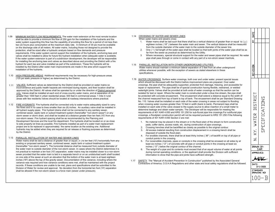
1.13 PARALLEL INSTALLATION OF WATER AND SEWER LINES
Water mains shall be laid a distance of greater than or equal ( ≥ ) to ten feet (10') horizontally from any
existing or proposed sanitary sewer, combined sewer, septic tank or subsoil treatment system
(hereinafter "non-storm sewer"). The horizontal distance shall be measured from outside diameter of
the water main to outside diameter of the non-storm sewer. In cases where the District determines it is
not practical to maintain a ten foot (10') separation, water mains may be installed closer to a non-storm
sewer provided that the water main is laid in a separate trench or on an undisturbed earth shelf located
on one side of the sewer at such an elevation that the bottom of the water main is at least eighteen
inches (18") above the top of the gravity sewer. Documentation of this variance, including where the
variance was required and how variance conditions were met, shall be maintained with the project
records. If these conditions are unable to be met, plans and specifications shall be submitted to the
Division of Water for review and approval. No deviation from the horizontal ten foot (10') separation
shall be allowed if the non-storm sewer is a force main (sewer under pressure).
VALVES Sufficient valves as determined by the District shall be provided on water mains so
inconvenience and public health hazards are minimized during repairs, and their location shall be
approved by the District. All valves shall be operated by or under the direction of District personnel
only. Valves shall be installed at each end of cross-country water mains, and at separation of no
greater than 1000 feet in urban residential areas; 500 feet in commercial areas; 1 mile in rural
areas with few residents.Valves should be located at roadway intersections where practical.
MINIMUM WATER FLOW REQUIREMENTS The water main extension at the most remote location
shall be able to provide a minimum fire flow of 250 gpm for the installation of fire hydrants and the
water system supporting this flow has the capability of providing this flow for a period of not less than
two (2) hours plus consumption at the maximum daily rate. A minimum of 30 psi must be available
on the discharge side of all meters. All water mains, including those not designed to provide fire
protection, shall be sized after a hydraulic analysis based on flow demands and pressure
requirements. If the water system cannot support the installation of fire hydrants, anchoring tees and
valves shall be installed to allow for future fire hydrant installation when adequate water is available.
If the water system extension is part of a subdivision development, the developer will be responsible
for installing the anchoring tees and valves as described above and providing the District with a fire
hydrant for each tee and valve installed as part of the subdivision. These fire hydrants will be
installed by the District after water main improvements are made in the area which support the
installation of fire hydrants.
HIGH PRESSURE AREAS Additional requirements may be necessary for high-pressure areas
(125 psi static pressure or higher) as determined by the District.
FIRE HYDRANTS Fire hydrants shall be connected only to water mains adequately sized to carry
fire flows and in no case to lines smaller than six (6) inches. An auxiliary valve shall be installed in
all hydrant supply pipes. Fire hydrant drains shall not be connected to any sanitary sewer,
combined sewer, septic tank or subsoil treatment system (hereinafter "non-storm sewer") or any
storm sewer or storm drain, and shall be located at a distance greater than ten feet (10') from any
non-storm sewer. Fire hydrant spacing shall be as recommended by the Planning and
Development Services and the local fire department. Fire hydrants shall be located on or as close
to side property lot lines as possible. Fire hydrants installed as part of a water main replacement
project are to be replaced in approximately the same location as the existing one. Additional
hydrants may be added when they are required for air release or flushing purposes as determined
by the District.
1.17
1.16
1.14
1.15 PARALLEL INSTALLATION WITH OTHER UNDERGROUND UTILITIES-
Water mains should maintain a minimum lateral separation of 3 feet from all other underground
utilities whenever possible, with the exception of sewers as stated elsewhere in these
specifications.
WATER CROSSINGS Surface water crossings, both over and under water, present special issues
which should be discussed with the District before improvement plans are prepared. Over water
crossings, the pipe shall be adequately supported, protected from damage, freezing, and accessible for
repair or replacement. The pipe shall be of special construction having flexible, restrained, or welded
watertight joints. Valves shall be provided at both ends of water crossings so that the section can be
isolated for test or repair. Where the water main is constructed under a blue line stream, the pipe shall
be protected with concrete encasement. This encasement shall extend a distance equal to the width of
the channel measured from top of bank to top of bank. The encasement shall be per Standard Drawing
No. 110. Valves shall be installed on each side of the water crossing in areas not subject to flooding
when crossing water courses greater than 15 feet in width (bank to bank). Permanent taps shall be
installed on each side of the valve closest to the supply source to allow insertion of a small meter to
determine leakage and obtain water samples. The Developer will be responsible for meeting the
requirements of 401 KAR 4:050 and KRS 151.250 for sub-fluvial pipe line crossings.For subfluvial pipe
crossings, a floodplain construction permit will not be required pursuant to KRS 151.250 if the following
requirements of 401 KAR 4:050 Section 2 are met:
SAFETY The "Manual of Accident Prevention In Construction" published by the Associated General
Contractors of America, O.S.H.A Regulations and other state and local safety regulations shall be followed.
CROSSING OF WATER AND SEWER LINES
When water mains and sewers cross:
1. Water mains shall be laid such that there shall be a vertical distance of greater than or equal to ( > )
eighteen inches ( 18" ) between the water main and sewer. The vertical distance shall be measured
from the outside diameter of the water main to the outside diameter of the sewer line.
2. One ( 1 ) full length of the water pipe shall be located so that both joints of the water pipe shall be as
far from the sewer as practical as determined by the Utility.
3. Where necessary, special structural support for the water and sewer pipes shall be required. No water
pipe shall pass through or come in contact with any part of a non-strom sewer manhole.
1. No material may be placed in the stream or in the flood plain of the stream to form construction
pads, coffer dams, access roads, etc. during construction of pipe crossings.
2. Crossing trenches shall be backfilled as closely as possible to the original contour.
3. All excess material resulting from construction displacement in a crossing trench shall be
disposed of outside the flood plain.
4. For erodible channels, there shall be at least thirty inches ( 36" ) of backfill on top of all pipe or
conduit points in the crossing.
5. For nonerodible channels, pipes or conduits in the crossing shall be encased on all sides by at
least six inches ( 12" ) of concrete with all pipe or conduit points in the crossing at least six
inches ( 12" ) below the original contour of the channel.
6. The weight of a pipe and its contents must exceed that of an equal volume of water at all points
during normal operating conditions, or the applicant shall provide the Division with sufficient
information to show that the pipe and joints have sufficient strength.
AutoCAD SHX Text
REVISION
AutoCAD SHX Text
BY
AutoCAD SHX Text
DATE
AutoCAD SHX Text
N. KY. WATER DISTRICT
AutoCAD SHX Text
APPROVED:
AutoCAD SHX Text
DATE:
AutoCAD SHX Text
STANDARD
AutoCAD SHX Text
DRAWING NO:
AutoCAD SHX Text
DRAWN BY:
AutoCAD SHX Text
SAR
AutoCAD SHX Text
100-B
AutoCAD SHX Text
SPECIFICATIONS
AutoCAD SHX Text
2/1/2021

1.18
1.19
1.20
PART II - MATERIALS
2.01 WATER MAIN PIPE AND FITTINGS
B.
1.21 ORGANIC CONTAMINATION
Mains installed within 200 feet of petroleum tanks and other areas of organic contamination must be
ductile iron pipe.
MAINTENANCE PERIOD The Developer shall be responsible for the maintenance of the installed
water mains and appurtenances to District Standards for a period of not less than one (1) year from
the date the water main is placed in service by the District. If an inspection reveals that the installation does
not meet District standards, the developer will be notified in writing to correct all discrepancies and/or
problems within 30 days after notification. If the problems are not corrected within the 30 day period, the
District shall make the corrections at the expense of the Developer. The Developer shall then be billed by the
District at a rate of time and material plus overhead or at the rate of actual cost plus overhead when
completed by an available contractor hired by the District. Payment is required within 30 days of invoice
date. Indebtedness to the Water District will result in no future water being provided to the Developer on all
existing and future water main projects and/or phases until all indebtedness is paid in full.
APPLICATION FOR SERVICE Application for water service will only be accepted after the water main
bacteria samples are shown to be negative following disinfection and the main is placed in-service by the
District. No service installation will be scheduled until the water main is approved and turned on.
CONDUITS FOR WATER SERVICES IN ROCKY AREAS The Developer is responsible for
notifying the District when rocky conditions are found in a development which could affect the
installation of customer water service lines. In rocky areas, the Developer shall install service line
conduits and be responsible for maintaining markings which identify the conduit's location. When
service connections in developments require rock boring as a result of a developer's failure to install
crossover conduits, the water service applicant will be billed for the full cost of the installation under
the District's Invoice Billing Policy, less the connection fee paid at the time of application. This will
apply to service connections tapped to water mains installed by a developer and put into service
after January 1, 2020. The word “rock” is defined as boulders and solid masonry larger than ½
cubic yard in volume, or solid ledge rock and masonry which requires for its removal, drilling and
blasting, wedging, sledging, barring, or breaking up with a power operated hand tool. Photo
evidence of rock encountered during service line installation is available upon request.
Minimum Class 50 Ductile Iron Pipe (D.I.P) - A minimum of Class 50 Ductile Iron pipe shall
conform to the latest edition of AWWA C151. All pipe shall be clearly marked as to class by the
manufacturer "Push-on single gasket" type joints shall conform to the latest edition of AWWA
C-111. Pipe shall have a standard thickness cement mortar lining in conformance with AWWA
C-104.
Under no conditions shall pipe line deflection measured between joints exceed the manufacturer's
published recommended standard for that type of pipe. The maximum deflection at push-on joints
and/or mechanical joints shall be 5 degrees or as recommended by Manufacturer. All D.I.P. shall
be blue polyethylene wrapped.
A.
Polyvinyl Chloride Pipe (P.V.C.) - D.R. 18, P.V.C. pipe shall conform to the latest edition of
AWWA C900, must be NSF approved and manufactured in accordance with ASTM standards. All
pipe shall be clearly marked as to class by the manufacturer. The outside diameter shall be
equivalent to D.I.P. Pipe shall have gasket bell end type joints furnished complete with gaskets
meeting the latest edition of ASTM F477. Solvent weld joints are prohibited.
P.V.C. pipe shall be permitted for use in residential subdivisions and along city and county roads
as approved by the District. Pipe size shall be limited to 6", 8" & 12". P.V.C. pipe shall not be
installed in high pressure areas where the static system pressures exceeds 125 psi or other
system conditions exist which increase pressures over 125 psi. as determined by the District.
P.V.C. pipe cannot be used for cross country lines, along state highways, water crossings, or
installed within 200 feet radius of oil or gasoline lines, underground storage tanks, petroleum
storage tanks or pumping stations.
P.V.C. pipe may be tied into an existing ductile iron main in a subdivision when the extension is
over 450 linear feet of main, or when the pipe is installed around a cul-de-sac or a dead-end
street with no possible extension of the street as approved by the District. Transition between
D.I.P. and P.V.C. pipe shall be made with some type of ductile iron fitting. Manufacturer
approved transition joints shall be used between dissimilar piping materials.
Beveled spigot ends must have a minimum bevel of 8 degrees to a maximum bevel of 15
degrees. The vertical face of the spigot end may not exceed 75% of pipe wall thickness and the
horizontal length of the bevel shall not exceed 1.25 inches. Field beveled spigot end shall be
made per manufacturers recommendation and as approved by the District. The degree of bevel
shall be approved for the type of pipe being installed.
P.V.C. Pipe Shipping, Handling & Storage - The front end of all pipe delivered by truck shall be
covered for protection against exhaust fumes.P.V.C. pipe shall be protected from exposure to
sunlight according to manufacturer's recommendations. Pipe will not be accepted for installation
if discoloration is evident due to sunlight or other exposure. Pipe shall be stored in such a manner
to prevent beaming the pipe.
C.
D.
Molecularly Oriented Polyvinyl Chloride Pressure Pipe (P.V.C.O.)
P.V.C.O. pipe shall conform to the latest edition of AWWA C909, must be NSF approved and
manufactured in accordance with ASTM standards. All pipe shall be clearly marked as to class by the
manufacturer. The outside diameter shall be equivalent to D.I.P. Pipe shall have gasket bell end type
joints furnished complete with gaskets meeting the latest edition of ASTM D3139. Solvent weld joints
are prohibited. P.V.C.O. pipe installation shall follow the P.V.C. C-900 Standards - Part II -Materials,
2.01, Section C of these specifications.
Polyethylene Pipe - Class 200, S.D.R. 9, 200 psi, ASTM D-2737, P.E. pipe shall conform to the latest
edition of AWWA C901, must be NSF approved and manufactured in accordance with ASTM standards.
All pipe shall be clearly marked as to class by the manufacturer. The outside diameter shall be equivalent
to Copper Tubing Size (CTS). The P.E. pipe shall be homogeneous throughout and free of visible cracks,
holes, kinks, foreign inclusions or other defects. It shall be uniform in color, opacity, density and other
physical properties. Solvent weld joints are prohibited.
P.E. pipe shall be permitted for use in residential subdivisions cul-de-sacs only as approved by the District.
Pipe size shall be limited to 2". P.E. pipe shall not be installed in high pressure areas where the static
system pressures exceeds 125 psi or other system conditions exist which increase pressures over 125 psi.
as determined by the District. P.E. pipe cannot be used for cross country lines, along state highways, water
crossings, or installed within 200 feet radius of oil or gasoline lines, underground storage tanks, petroleum
storage tanks or pumping stations.
P.E. pipe expands and contracts when exposed to temperature changes, allowances shall be made during
installation. Normally P.E. pipe will "snake" itself in the trench enough to provide sufficient slack. An extra
6" per 100' of pipe per 45 F temperature change should be added to compensate for thermal conditions.
AutoCAD SHX Text
REVISION
AutoCAD SHX Text
BY
AutoCAD SHX Text
DATE
AutoCAD SHX Text
N. KY. WATER DISTRICT
AutoCAD SHX Text
APPROVED:
AutoCAD SHX Text
DATE:
AutoCAD SHX Text
STANDARD
AutoCAD SHX Text
DRAWING NO:
AutoCAD SHX Text
DRAWN BY:
AutoCAD SHX Text
SAR
AutoCAD SHX Text
100-C
AutoCAD SHX Text
SPECIFICATIONS
AutoCAD SHX Text
2/1/2021

E.
F.
2.02
2.03
A.
Tracing Wire All water mains, including out-of-service stubs intended for future extension, shall
be installed with copper tracing wire (P.V.C. coated) taped to the top of the pipe every 5'. Maximum
tracing wire length shall be 500' without terminating in a curb stop box. Curb stop boxes shall not be
located in the pavement areas. Splices in the tracing wire shall be kept to a minimum and approved
by the District. If splices are required they shall be made with copper split bolt (lisco #ik-8 or
approved equal) and taped with electrical tape. Jumper wires must be run from the main tracing
wire and secured to all water meter service lines.
Fittings - All fittings and accessories shall be Ductile Iron, rated for a minimum of 200 psi working
pressure or as specified herein. The fittings and accessories shall be new and unused. (NOTE: Certain
areas of the Northern Kentucky Water District require materials used, to be of a higher working pressure
than 200 psi.) All pipe fittings shall be mechanical joint fittings. Mechanical joints shall conform to
AWWA C111. Bolts and nuts shall be high strength, corrosion resistant alloy, such as "Cor-Ten" or
approved equal. Ductile Iron Compact Fittings shall conform to AWWA C153 and Full Body Fittings to
AWWA C110. A bituminous seal coat shall be applied to the outside of the fitting. All ductile iron fittings
shall be cement lined and seal coated in accordance to AWWA C104.
POLYETHYLENE WRAP All ductile iron pipe, fittings, valves, and fire hydrant leads shall be polyethylene
wrapped, installed according to the current edition of AWWA C105. Polyethylene wrap shall be blue in
color. Ductile iron fittings,valves, and fire hydrant leads used in the installation of P.V.C. pipe shall be
included. Polyethylene wrap shall be 8-mill thickness low-density film or 4-mil thickness high-density
cross-laminated polyethylene tube per AWWA C105. The contractors shall cut the roll in tubes 2 feet
longer than a standard length of pipe.
Each tube shall be slipped over the length of pipe, centering to allow a one foot overlap on each
adjacent pipe section. After the lap is made, slack in the tubing shall be taken up for a snug fit. and
the overlay shall be secured with polyethylene tape. Pipe shall not be wrapped and stored on site for
any period of time, but wrapped and immediately placed in the trench, fittings shall be wrapped prior
to installing blocking or pads. (see Standard Drawing #104) Polyvinyl chloride pipe requires no wrap.
Odd shaped appurtenances such as valves, tees, fittings, and other ferrous metal pipeline
appurtenances shall be wrapped by using a flat sheet of polyethylene. Wrapping shall be done by
placing the sheet under the appliances and bringing the edges together, folding twice, and taping
down.
VALVES All valves shall open by turning counter-clockwise with the operation of a 2 inch square
operating nut. All valves shall have openings through the body of the same circular area as that of
the pipe to which they are attached. Valves shall have mechanical joint ends except Tapping Valves.
GATE VALVES Valves 12 inches and smaller shall be resilient seated gate valves, non-rising
stem with rubber "O" ring packing seals, rated at 250 psi working pressure and conform to the
applicable portions of AWWA Standard C509, Latest Edition. High pressure gate valves shall
be required when the pressure exceeds 200 psi. Valve bodies shall be ductile iron, glands
shall be the same material as the valve. All external dome and packing bolts shall be stainless
steel. The valves shall open by turning counter-clockwise. All valves shall have openings
through the body of the same circular area as that of the pipe to which they are attached.
Valves shall have mechanical joint ends unless otherwise shown on the plans or directed by the
District. An extension stem shall be furnished if required, to bring the operating nut within 3-1/2
feet of finished grade. Extension stems shall be securely fastened to the valve stem. The
Contractor shall make all valves tight under their working pressures after they have been placed
and before the main is placed in operation. Unless otherwise approved by the District, all valves 16"
and larger shall be ductile iron resilient wedge gate valves with beveled gearing (lay down gate
valves). Valve shall be ductile iron body, non-rising stem, open left, 2" square operating nut, epoxy
coated, mechanical joint (inlet & outlet connections), O-ring type packing, resilient wedge, 250 psi
working pressure, and conforming in all other ways to AWWA Standard C515 American Flow Control
2500 Resilient Wedge Gate Valve or approved equal. Valve body, external dome, and packing bolts
to be assembled with stainless steel bolts grade 304 or better.
TAPPING SLEEVE AND VALVES - No tapping sleeves and valves unless approved by Northern
Kentucky Water District. Tapping sleeves and valves shall be designed for a working pressure of 200
psi. The tapping sleeve together with the tapping valve shall be tested at 250 psi for visible leakage
before the main is tapped. Tapping sleeve and valve used in high pressure areas shall be tested at
350 psi.
B.
1. Tapping Sleeves - Tapping sleeves shall be a two piece body with mechanical joint type ends,
and be so designed as to assure uniform gasket pressure and permit centering of the sleeve on the
pipe. Stainless steel type tapping sleeves with full gasket maybe considered, but will need to be
approved by the District prior to installation.
2. Tapping Valves - Tapping valves shall be resilient seated gate valves, rated at 200 psi (unless
installed in high pressure service area) and conform to the applicable portions of AWWA
Standard 509, latest edition except that the seat rings shall be oversized to permit entry of the
tapping machine cutter. All external dome and packing bolts shall be stainless steel. Tapping
valves shall be ductile iron body, non-rising stem with rubber "O" ring packing seals. Tapping
valves shall have a flange on one end for bolting to the tapping sleeve and a mechanical joint
type end connection on the slotted standard flange or other adapters for connection to the
tapping machine.
C. VALVE STEM EXTENSIONS A valve stem extension shall be installed by the contractor to
bring the operating nut within 2 1/2 to 3 1/2 ft. of final grade. Extension stems will be supplied
by the Water District if the extension is justified. The contractor shall measure the needed
length and provide a minimum of 48 hours notice for receipt of stem extension.
B. Water mains greater than or equal to (≥) 16 inches in diameter which contain metallic piping and/or fittings
shall be installed with cathodic protection designed by a NACE certified corrosion specialist. This specialist
shall be responsible for:
- Performing field soil analysis/survey along a proposed water main project alignment.
- Review design drawings and material specifications prepared by others and provide
recommendations for consideration.
- Providing all necessary and appropriate services in connection with conducting corrosion evaluation
of the proposed project, corrosion protection analysis, design installation
details/schedule/specifications.
- Preparation of standard corrosion protection specification for inclusion with the District's
specifications.
- Review the proposed pipe material and provide recommendations on cathodic protection/control
and/or protective coatings.
- Providing a report/recommendations for the long-term cathodic protection of the proposed project
which could include the following: the size, type, configuration, quantity, and spacing of
recommended galvanic anodes, joint bonding, isolation couplings, wiring, etc.; all soil
analysis/measurements, calculations, locations, corrosion monitoring & test stations; and provisions
to mitigate DC interference to nearby metallic structures.
AutoCAD SHX Text
REVISION
AutoCAD SHX Text
BY
AutoCAD SHX Text
DATE
AutoCAD SHX Text
N. KY. WATER DISTRICT
AutoCAD SHX Text
APPROVED:
AutoCAD SHX Text
DATE:
AutoCAD SHX Text
STANDARD
AutoCAD SHX Text
DRAWING NO:
AutoCAD SHX Text
DRAWN BY:
AutoCAD SHX Text
SAR
AutoCAD SHX Text
100-D
AutoCAD SHX Text
SPECIFICATIONS
AutoCAD SHX Text
2/1/2021

2.05
2.06
2.07
2.08
PART III - INSTALLATION OF WATER MAINS AND APPURTENANCES
3.01
AIR RELEASE VALVES AND/OR TAPS Air release valves shall be installed in the high points of
the water mains where hydrants are not installed and as required by the District and in accordance
with Standard Drawing No. 106. 8" and smaller water mains, tap size and piping shall be 3/4", 12"
water main-1",& 16" and larger water main-2". Temporary taps of suitable size may be required
at certain points on the water main for the release of air for filling and/or flushing purposes.
Temporary taps will be removed and plugged after use. Automatic air relief valves shall not be used in
situations where manhole or chamber flooding may occur. The open end of an air relief pipe from
automatic valves shall be extended a distance of greater than or equal to ( ≥ ) one foot (1') above grade
and shall be provided with a screened, downward facing elbow or an equivalent standard as determined
by the best professional judgment of the District. Manually operated air release valves shall include a
camlock-type coupling and waste valve.The pipe from a manually operated air release valve shall be
extended to the top of the pit.
2.04 VALVE BOXES All valves shall be provided with valve boxes. Valve boxes shall be of standard,
adjustable, heavy duty cast iron extension type, two piece, 5 1/4 inch shaft, screw type, and of such
length as necessary to extend from valve to finished grade, Tyler #562-S, Tyler #564-S or approved
equal. Valve box cover shall be stamped "Water". Tops shall be set at final established grade. If valve
boxes are not of sufficient height to bring the top of the box to final grade, a section of 6" ductile iron pipe for
pavement areas and 6" PVC for non-pavement areas may be used to extend the valve box to final grade
with prior approval from the District. The length of pipe shall permit the valve box to be adjusted up and
down. All valves will be installed with a box-lok type valve box centering ring or approved equal.
FIRE HYDRANTS All fire hydrants shall have auxiliary valves for isolating water flow to the hydrant. All
fire hydrants and auxiliary valves shall be positively locked to the water main by restrained joints, hydrant
adapters, or other approved method. Hydrants shall be designed to 200 psi working pressure and shall be
shop tested to 300 psi hydrostatic pressure with the main valve both open and closed. High pressure fire
hydrants will be required when pressures exceed 150 psi.
The barrel shall have a breakable safety section and/or base bolts just above the ground line. Hydrants
shall have a main valve opening of 5 1/4 inches, a 6 inch mechanical joint inlet to be suitable for setting in
a trench 3' 6" deep minimum, and shall be the traffic style hydrant so that the main valve remains closed
when the barrel is broken off. Hydrants shall have a dry top and shall be self draining, when the main
valve is closed. Self draining hydrants shall drain to dry wells provided exclusively for that purpose.
Hydrant drains shall not be connected to storm or sanitary sewers. Hydrants located generally in the
Covington System and other areas determined by the District (flood zones) shall have all drain holes
plugged prior to installation. Hydrants shall be rotatable in a minimum of eight (8) position in 360 degrees.
All hydrants shall have two (2) - two and one half (2 1/2) inch hose nozzles and one (1) steamer or pumper
connection threaded to conform to Northern Ky. Water District's Standards: steamer nozzle shall be National
Standard Thread and 2 1/2" outlets shall be Old Cincinnati Thread. The operating nut and the nuts of the
nozzle caps shall be square in shape, measuring one (1) inch from side to side. Hydrant body shall be
painted yellow for areas designed for 150 psi working pressure and red for areas in excess of 150 psi.
All hydrants shall be right hand open, clockwise. The following fire hydrants are approved for installation in
the District's system: Mueller, Waterous,U.S. Pipe, M & H , Kennedy and American Darling.
PRESSURE REDUCING VALVES Pressure reducing valves will be installed by the District in regular 2" and
smaller meter settings when the static system pressure is at or above 125 psi for new and old services when
deemed necessary by the District. Pressure reducing valves are only installed to protect the meter. The
District will not be liable for any damage due to pressure conditions caused by or arising out of the failure or
defective condition of such pressure regulator or for damage that may occur through the installation,
maintenance, or use of such equipment.
STEEL CASING PIPE Casing pipe shall be steel pipe with a minimum yield strength of 35,000 psi
with a minimum wall thickness as listed below:
Nominal | Nominal
Diameter Casing Normal Wall | Diameter Casing Normal Wall
Pipe Thickness | Pipe Thickness
Under 14" 0.251" | 26" 0.438"
14" & 16" 0.282" | 28" & 30" 0.469"
18" 0.313" | 32" 0.501"
20" 0.344" | 34" & 36" 0.532"
22" 0.375" | 38", 40", & 42" 0.563"
24" 0.407" | 48" 0.626"
The inside diameter of the casing pipe shall be at least four (4) inches greater than the outside
diameter of the carrier pipe joints. Steel casing sections shall be connected by welding, conforming
to AWWA C206. All carrier pipe placed in steel casing pipe shall be minimum class 50 ductile iron
pipe and conform to the latest edition of AWWA C151. Carrier pipe gaskets shall develop a wedging
action between pairs of high-strength stainless steel elements spaced around the gasket (FIELD
LOK , FASTGRIP or approved equal gaskets). Adequate pipe spacers shall be installed to ensure
that the carrier pipe is adequately supported in the center of the casing pipe throughout it's length,
particularly at the ends to offset settling and possible electrical shorting. Manufactured pipe spacers
shall be installed per manufacture's installation requirements. There shall not be any metallic contact
between the casing and carrier pipe. Casings shall have both ends sealed up in such a way as to
prevent the entrance of foreign material. See Standard Drawing #114 for installation details.
GENERAL Water mains and appurtenances shall be installed in compliance with AWWA standards
(C600 for D.I.P, C605 for P.V.C. type pipe and C901 for P.E.) and/or manufacturer recommendations.
Water main pipe and fittings shall be laid on a good level foundation with no gaps or humps under
the pipe or fittings. Excavation shall be done by hand at joints to prevent the pipe and fittings from
being supported by the mechanical joint or slip joint bell. Transition between D.I.P. and P.V.C. type
pipe shall be made with some type of ductile iron fitting. Manufacturer approved transition joints shall
be used between dissimilar piping materials. Repairs to or section replacement of D.I.P. shall not be
made using P.V.C. materials. Pipe shall be laid with the bell ends facing in the direction of laying.
AutoCAD SHX Text
REVISION
AutoCAD SHX Text
BY
AutoCAD SHX Text
DATE
AutoCAD SHX Text
N. KY. WATER DISTRICT
AutoCAD SHX Text
APPROVED:
AutoCAD SHX Text
DATE:
AutoCAD SHX Text
STANDARD
AutoCAD SHX Text
DRAWING NO:
AutoCAD SHX Text
DRAWN BY:
AutoCAD SHX Text
SAR
AutoCAD SHX Text
100-E
AutoCAD SHX Text
SPECIFICATIONS
AutoCAD SHX Text
2/1/2021

3.03
3.04
3.05 TRENCH EXCAVATION
3.06
3.07
3.08
If the interruption of service to any customer of the District is necessary, the Contractor shall make
arrangements to provide such shutdown and notify District customers at the direction of the District
Inspector. All private residents shall be notified no less than 48 hours and all businesses commercial and
Industrial customers shall be notified no less than 1 week prior to the interruption of service. All
shutdowns shall be coordinated with the effected residents, with priority given to any special needs
customers such as hospitals, schools, and customers with medical needs.
A.
3.02 CONTRACTORS RESPONSIBILITY If the existing water main being tapped or connected to is cathodically
protected, an isolation coupling shall be required. All work performed on any water mains and/or
appurtenances that are owned or anticipated to be owned by the District shall be completed under the
direction of the District adhering to an acceptable plan approved by the District. A minimum 24 hours notice
shall be given to the District by the contractor prior to the start of water main work. One set of District approved
plans shall be on the job site during construction. Water main construction will not be permitted to start until all
approvals are received. There shall be no deviation from the approved plans without written approval from the
District.
The interior of the pipe shall be thoroughly cleaned of foreign matter before being lowered into the trench
and shall be kept clean during laying operations. ALL OPEN ENDS ARE TO BE CLOSED WITH CAPS
OR PLUGS AT ALL TIMES WHEN PIPE LAYING OPERATIONS ARE NOT IN OPERATION AND AT
THE END OF THE DAY. All caps or plugs shall be properly installed and blocked in advance of filling,
flushing, and testing mains. All securing and blocking shall be inspected by the District prior to back
filling of ditch.
If the existing water main material being tapped or connected to is asbestos concrete, then during
the process of tapping the asbestos concrete water main, the contractor shall conform to OSHA
regulations governing the handling of hazardous waste. Pieces of asbestos concrete resulting from
the tap shall be doubled bagged, placed in a rigid container and disposed of in an approved landfill.
Contractor shall be responsible for relieving any water main pressure (whether air or water)
before removing any cap, plug, fire hydrant, valve, etc.
B.
HANDLING Pipe, fittings, valves, hydrants, and accessories shall be loaded and unloaded by lifting
with hoists or skidding so as to avoid shock or damage. Pipe hooks that extend inside the ends of
the pipe shall not be used for handling the pipe since they could damage the lining. Under no
circumstances shall such materials be dropped. Pipe handled on skid ways shall not be skidded or
rolled against other pipe. All bolts shall be tightened with proper wrenches and must have equal
tension. The interior of all pipe, fittings and other accessories shall be kept free from dirt and
foreign material at all times. When handling P.V.C., P.V.C.O. & P.E. pipe care should be taken to
avoid abrasion damage, gouging of the pipe, rocks, and any stressing of the bell joints or damage
of the bevel ends.
TRENCHING, GRADE, AND COVER Typically no trenching or laying of pipe or fittings shall be
done until pavement (curbs) has been installed. In cases where water main installation is required
under new pavement (side streets) main may be installed from trench stakes. When main
installation is done prior to the pavement completion, test holes may be required by the District if
valve depth, service taps or other evidence indicates that the minimum or maximum cover
requirements are not met or that the main is in the wrong location. The contractor will be
responsible for digging test holes at intervals required by the District to verify depth and location.
All trenching, grade, and cover work shall conform to the lines and grades established, and shall be
done according to the drawings and specifications, subject to such modifications as the District may
determine to be necessary during the execution of the work. Trenches for water lines shall be of a
depth that will provide a minimum cover over the top of pipe of three (3) feet and a maximum of four
(4) feet from the final finished grade. Cover over four feet in depth will not be allowed unless
approved by the District to avoid interference with other utilities. Kentucky Dept. of Transportation
requires a minimum of 42" of cover for water mains along state highways.
The Contractor shall establish all locations, lines, and grades in advance of all work where practical.
In addition the Contractor will keep the Northern Kentucky Water District informed a reasonable
time in advance of the times and places in which the Contractor intends to work (minimum advance
notice shall be one working day, 24 hours).
A. TRENCH WIDTH Widths of trenches shall be held to a minimum to accommodate the pipe and
appurtenances. The trench width shall be measured at the top of the pipe barrel and shall
conform to the following limits:
Earth
Minimum - outside diameter of the pipe barrel plus 8 inches, 4 inches each side of pipe.
Maximum - nominal pipe diameter plus 24 inches.
Rock
Minimum - 24" or less, nominal pipe size: outside diameter of pipe barrel plus 12 inches, @ 6 inches
each side.
Minimum - Larger than 24", nominal pipe size: outside diameter of pipe barrel plus 18 inches, @
9 inches each side.
Maximum - nominal pipe diameter plus 24 inches.
B. BUTTERFLY VALVES
Trench width shall be over excavated 24" on the side that the operating mechanism is located on the
butterfly valve when the surrounding area cannot be hand dug.
BOTTOM PREPARATION The Contractor shall use excavation equipment that produces an even
foundation. For the entire length of the trench, a compacted 3" layer of sand, shall be installed below
the pipe. Bell holes and depressions for joints, valves, and fittings shall be dug after the trench
bedding has been graded in order that the pipe rest upon the prepared bedding for as nearly its full
length as practicable. Bell holes and depressions shall be only of such length, depth, and width as
required for properly making the particular type of joint. Stones found in the trench shall be removed
for a depth greater than or equal to ( ≥ ) six inches (6") below the bottom of the pipe.
UNSTABLE SUB-GRADE MATERIAL When the sub-grade is found to include non-approved
backfill material (rock, refuse, organic material, etc.), such material shall be removed to a minimum
of six (6) inches below the bottom of the pipe and backfilled with sand, backrun or granular material
and thoroughly compacted.
UNSTABLE SUB-GRADE If the material forming the trench bottom is not suitable for a good
foundation, a further depth shall be excavated and backfilled with an approved backfill material and
thoroughly compacted or a foundation shall be constructed using piling, treated timbers, concrete,
or other materials as directed and approved by the District.
AutoCAD SHX Text
REVISION
AutoCAD SHX Text
BY
AutoCAD SHX Text
DATE
AutoCAD SHX Text
N. KY. WATER DISTRICT
AutoCAD SHX Text
APPROVED:
AutoCAD SHX Text
DATE:
AutoCAD SHX Text
STANDARD
AutoCAD SHX Text
DRAWING NO:
AutoCAD SHX Text
DRAWN BY:
AutoCAD SHX Text
SAR
AutoCAD SHX Text
100-F
AutoCAD SHX Text
SPECIFICATIONS
AutoCAD SHX Text
2/1/2021

3.09
3.10
PIPE LAYING Pipe shall be laid with bell ends facing in the direction of laying. After placing a length
of pipe in the trench, the spigot end shall be centered in the bell and the pipe forced home.
All pipe shall be laid with ends abutting and true to line and grade. Deflection of pipe joints in
excess of the manufacturer's recommendations shall not be permitted. Caps or plugs shall be
installed to prevent the entrance of foreign material whenever pipe laying operations are not in
progress.
PIPE CUTTING Cutting of pipe for installing valves, fittings, or hydrants shall be done in a neat and
workmanlike manner without damage to the pipe or lining. The end shall be smooth and at right
angles to the axis of the pipe. Flame cutting of metal pipe by means of an oxyacetylene torch shall
not be permitted.
3.14
3.15
3.16
3.17
3.18
3.19
3.20
3.11
3.12
3.13
PUSH-ON JOINTS The surfaces with which the rubber gasket comes in contact shall be thoroughly
cleaned just prior to assembly. The gasket shall then be inserted into the groove in the bell. Before
starting joint assembly, a liberal coating of special lubricant, per manufacturers recommendation,
shall be applied to the spigot end. (Special lubricant shall be suitable for use in potable water) With
the spigot end centered in the bell, the spigot is pushed home per manufacturers recommendations.
Insertion of spigot into PVC type pipe bell should be inserted until the reference mark is flush with
the end of the bell. Over insertion of the pipe is not recommended per the manufacturer. Pipe joint
materials which prevent permeation by petroleum products shall be used within 200 foot radius of oil
or gasoline lines, underground storage tanks, petroleum storage tanks or pumping stations.
MECHANICAL JOINTS Mechanical joints for D.I.P. and P.V.C. type pipe require that the spigot be
carefully located in the bell. The surfaces with which the rubber gasket comes in contact shall be
thoroughly cleaned just prior to assembly. These clean surfaces shall be brushed with a special
lubricant just prior to slipping the gasket over the spigot end and into the bell. (Special lubricant shall
be suitable for use in potable water) The lubricant shall also be brushed on each gasket prior to
installation to remove the loose dirt and lubricate the gasket as it is force into its retaining space.
P.V.C. type pipe spigot ends shall be field cut smooth and at right angles to the axis of the pipe for
installation in mechanical joint fittings. Care shall be taken to ensure that the P.V.C. plain end is
completely home into the mechanical joint fitting.
RESTRAINED JOINTS Restrained joint-type pipe and fittings shall only be used as approval by
the District. Retaining glands, field lock gaskets, or retaining flanges maybe used as temporary
blocking but shall not be considered as providing a permanent restrained joint or as an alternate
for permanent concrete blocking. The use of these type of restraining joints need to be approved
by the District prior to installation.
SETTING VALVES Valves shall be set on a firm solid concrete block foundation so that no load will
be transferred to the connecting pipe. Valves in water mains shall, where possible, be located on
the side property lines extended, unless otherwise shown on the plans. A valve box shall be
provided for every valve. The valve box shall not transmit shock or stress to the valve and shall be
centered and plumb over the operating nut of the valve. The box cover shall be set flush with the
surface of the finished pavement unless otherwise shown. All valves boxes with the exception of
isolating valves for fire hydrants that are located in non-paved areas shall have a minimum 2' by 2'
by 4" concrete pad as shown in Standard Drawing No. 105, unless a smaller pad is approved by the
District.
SETTING FIRE HYDRANTS Hydrants shall be located as shown on the plans or as directed by the
District. The location shall provide complete accessibility and minimize the possibility of damage
from vehicles or injury to pedestrians. All hydrants shall stand plumb with the pumper nozzle facing
the curb. Hydrant shall be set to the established grade, with the traffic flange within 4" above final
grade in accordance to Standard Drawing No. 109. Each hydrant shall be controlled by an
independent gate valve with valve box. All valves used for hydrant control shall be anchored to the
branch tee. Fire hydrant barrel extension shall be limited to a one piece assembly only, stacking
two or more extensions is prohibited. Maximum fire hydrant barrel extension is 2 feet.
CROSS-COUNTRY WATER MAINS All cross-country water mains shall be installed with a tracing
wire as described in Part II, Section 2.01 - F- Tracing Wire.
THRUST BLOCKING All bends over five (5) degrees, tees, plugs, reducers, and hydrants shall be
securely blocked against movement with concrete thrust blocks placed against undisturbed earth in
accordance with Standard Drawing No. 104 & 104-A. Thrust blocks shall be approved by the District
prior to backfilling. Water mains shall have concrete thrust block at all pipe intersections and
changes of direction to resist forces acting on the pipeline. All concrete thrust blocks shall be poured
in such a manner that the bolts can be replaced without disturbing the blocking. All caps or plugs
used in mains to undergo hydrostatic test shall be properly installed and blocked in advance of
testing mains. All caps or plug installations shall be approved by the District representative before
the main is subjected to the pressure test. The District may permit the use of restrained type glands,
gaskets, 3/4" welded eye bolts @ a 90 degree bend & 3/4" threaded rods or other means as prior
approved by the District for temporary restraint only. Permanent concrete thrust restraint shall be
provided with any temporary restraint. Duc-Lucs are prohibited for use.
TRENCH BACKFILL TO 12" OVER PIPE BARREL All trench excavations shall be backfilled
immediately after pipe is laid with the exception of thrust blocks. Compacted sand material shall be
used to backfill the trench from the bottom of the pipe barrel to the 12" over the pipe barrel Lime
sand is not permitted. Backfill material shall be free from cinders, refuse, organic material, boulders,
top soil, frozen material, material with a high void content, rocks 1 1/2" or larger measured in any
direction, sharp stones and crushed rocks larger than 3/4", or other materials which in the opinion
of the District is unsuitable. No flushing of backfill shall be permitted to achieve compaction.
REMAINING TRENCH BACKFILL IN NON-PAVEMENT AREAS From 12" above the pipe barrel
to the surface, excavated trench material may be used as backfill material or as required by local or
county authorities. No material shall be used for backfill that contains frozen earth, vegetable or
organic material, debris, rocks 8" or larger measured in any direction, or earth with an exceptionally
high void content. Compaction of remaining trench backfill shall be as required by local or county
authorities.
REMAINING TRENCH BACKFILL IN EXISTING PUBLIC ROADWAYS Roadway opening permits
shall be obtained from the local City, County or Ky. State Dept. of Highways if applicable. The
minimum requirements for backfill beneath all existing public roadways from 12" above the pipe
barrel to sub-grade shall be flowable fill unless City, County, or State have additional requirements.
The flowable fill shall comply with the latest edition of the Kentucky Transportation Cabinet/
Department of Highways "Standard Specifications for Road and Bridge Construction".The remaining
trench backfill to final grade shall match the existing pavement/surface conditions.
AutoCAD SHX Text
100-G
AutoCAD SHX Text
SPECIFICATIONS
AutoCAD SHX Text
REVISION
AutoCAD SHX Text
BY
AutoCAD SHX Text
DATE
AutoCAD SHX Text
N. KY. WATER DISTRICT
AutoCAD SHX Text
APPROVED:
AutoCAD SHX Text
DATE:
AutoCAD SHX Text
STANDARD
AutoCAD SHX Text
DRAWING NO:
AutoCAD SHX Text
DRAWN BY:
AutoCAD SHX Text
SAR
AutoCAD SHX Text
2/1/2021

3.21 DISINFECTION New or relocated water mains shall be thoroughly disinfected in accordance with 401
KAR Chapter 8:150 Section 4 (1) upon completion of construction and before being placed into
service. To disinfect the new or relocated lines, the Utility shall use chlorine or chlorine compounds
(disinfectants) in such amounts as to produce an initial disinfectant concentration of at least fifty (50)
ppm and a residual disinfection of greater than or equal to ( ≥ ) twenty-five (25) ppm at the end of
twenty four (24) hours. The line disinfection shall be followed with thorough flushing and the lines shall
be placed into service if, and only if, coliform monitoring of the line does not show the presence of
coliform. If coliform is detected, repeat flushing of the line and coliform monitoring. If coliform is still
detected, repeat disinfection and flushing as if the line has never been disinfected. Continue the
described process until monitoring does not show the presence of coliform. The application shall be as
approved by the District and in accordance with AWWA C651 and applicable Ky. Division of Water
requirements.The presence or absence of total coliform monitored by sampling and analysis as
needed shall be determined for the new or relocated water main(s). Samples shall be taken at
connection points to existing lines at one (1) mile intervals and at dead ends, and from each branch of
the new or relocated water main. Sample bottles shall be clearly identified as "special" construction
tests. For new construction projects, the distribution system, using the most expedient method, shall
maintain coliform test results. Chlorinated water resulting from disinfection of project components shall
be disposed in a manner which does not violate 401 KAR 10:030.The contractor shall be responsible
for de-chlorination of the disinfection water. All non-disinfected fittings used for tie-ins or repairs shall
be cleaned and swabbed with a hypochlorite disinfecting solution prior to installation.
3.22 PRESSURE TESTING and Leak Detection. All installed pipe shall be monitored for leaks by physical testing,
as needed. Pressure Testing must be in accordance with the latest edition of AWWA Standards C600. The
water main being tested shall have all air expelled by additional flushing or the installation of taps on high
points in the line. The pressure of the water main shall be gradually increased to obtain a minimum pressure of
100 psi over the design pressure (250 psi minimum) at the lowest elevation point of the water main or as
directed by the District. The test will be for a two (2) hour duration and will not vary by more than 5 psi. All tests
performed for each test section shall be witnessed and approved by a representative of the District, in the
event any test is performed without a representative of the District, the Contractor shall be required to test the
section again. Leakage is defined as the amount of water used to maintain the test pressure.
A. TABLET METHOD Calcium hypochlorite tablets shall be installed in each length of pipe to
insure a sufficient dosage of 50 ppm based on the following table:
Pipe Diameter Tablets per Length
6" 2 ea. -5 gram tablets
8" 4 ea. -5 gram tablets
10" 6 ea. -5 gram tablets
16" 14 ea. -5gram tablets
12" 8 ea. -5 gram tablets
B. LIQUID CHLORINE METHOD
of chlorine in the form of liquid sodium hypochlorite as per AWWA B300 to obtain the results
as the previous method described. Note: Permission for this method of disinfection shall be
obtained by the District prior to construction.
Cross Connections Cross connections shall not be allowed, in accordance with 401 KAR 8:020.
3.23
Disinfection may be done by the addition of suitable amounts
The tablets shall be attached by an adhesive meeting the requirements of NSF/ANSI 61.
Tablets shall be attached inside and at the top of the main with approximately equal numbers
of tablets at each end of the pipe. Tablets must be water soluble.
AutoCAD SHX Text
100-H
AutoCAD SHX Text
SPECIFICATIONS
AutoCAD SHX Text
REVISION
AutoCAD SHX Text
BY
AutoCAD SHX Text
DATE
AutoCAD SHX Text
N. KY. WATER DISTRICT
AutoCAD SHX Text
APPROVED:
AutoCAD SHX Text
DATE:
AutoCAD SHX Text
STANDARD
AutoCAD SHX Text
DRAWING NO:
AutoCAD SHX Text
DRAWN BY:
AutoCAD SHX Text
SAR
AutoCAD SHX Text
2/1/2021

NO SERVICES
between hydrant & valve.
Hydrant
6"-8" Reducer
Temporary Dead-End
Blocking
Property Line or
Boundry to Future
Developable Section
Property Line orBoundry to Future
Developable Section
Plug
Line not placed in
service until extended
to next mainline valve
& hydrant
Valve to remain closed
until placed in service
3 Valves & Tee
Typical Lot Line
Valve
Temporary Dead-End
Blocking
6"-8" Reducer
No Service between
hydrant & valve
Last pipe
joint before
Dead-End
Bell
Joint
Bell Joint
Direction
of F
low
Direction
of F
low
To D
ead-E
nd
with B
locking
To D
ead-E
nd
with B
locking
4'0" M
in.
6"
Min.
6"
Min.
6"
Min.
6"
Min.
150 PSI DESIGN
Blocking (See STd)
Valve
Hydrant (See Std)
Anchoring Pipe
Anchoring Tee
(See Std)
Lot Line
Blocking shall be Class "A" Concrete or
Flowable Fill as approved by the District.
DETAIL FOR TEMPORARY
DEAD-END BLOCKING
NOTE: Blocking shall be inspected by the
District prior to backfilling.
CUL-DE-SAC WITH DEAD-END
FIRE HYDRANT
FUTURE SIDE STREET WITHOUT
SERVICES ON BRANCH LINE
Water Mains under paved surface shall not exceed
maximum 30 lin.Ft.,this does not apply to streer intersections.
FUTURE SIDE STREET WITH
SERVICE ON BRANCH LINE
DEAD-END STREET WITH PROPOSED
FUTURE EXTENSION
1.
th
e 3
0' u
nd
er p
ym
t. n
ot fo
r in
te
rse
ct.
De
ta
il te
mp
. d
ea
d-e
nd
b
lo
ckin
g
MP
S
MP
S
1/1
5/9
3
9/2
2/9
3
AutoCAD SHX Text
V
AutoCAD SHX Text
V
AutoCAD SHX Text
V
AutoCAD SHX Text
V
AutoCAD SHX Text
V
AutoCAD SHX Text
V
AutoCAD SHX Text
V
AutoCAD SHX Text
V
AutoCAD SHX Text
V
AutoCAD SHX Text
6"
AutoCAD SHX Text
Min.
AutoCAD SHX Text
6"
AutoCAD SHX Text
Min.
AutoCAD SHX Text
WATER MAINS TERMINATIONS
AutoCAD SHX Text
101
AutoCAD SHX Text
REVISION
AutoCAD SHX Text
BY
AutoCAD SHX Text
DATE
AutoCAD SHX Text
N. KY. WATER DISTRICT
AutoCAD SHX Text
APPROVED:
AutoCAD SHX Text
DATE:
AutoCAD SHX Text
STANDARD
AutoCAD SHX Text
DRAWING NO:
AutoCAD SHX Text
DRAWN BY:
AutoCAD SHX Text
SAR
AutoCAD SHX Text
2/1/2021

Water Main
Pavement
R/W
R/W
STREET WITHOUT SIDEWALK
3'
Water Main
Pavement
R/W
R/W
3'
STREET WITH SIDEWALK
Water
Meter Box
Cru
b L
in
e
ST
RE
ET
Wa
te
r M
ain
Sidewalk
Customer's
Service Line
Rig
ht o
f W
ay L
in
e
Fire
Hydrant
Sidewalk
All ductile iron pipe, fittings and valves shall be wrapped with
polyethelene encasement in accordance with specifications.
DRAWING NOTES
Mechanical Joint Anchoring Tee-Clow No.F-1217
or equal as approved.
Mechanical Joint Gate Valve
Mechanical Joint Anchoring Pipe
Clow No.F-1216 or Approved equal
Length as required.
1.
The 30' under pym
t. not for intersect.
Detail tem
p. dead-end blocking.
MP
S
1/15/93
9/22/93
MP
S
AutoCAD SHX Text
C
AutoCAD SHX Text
L
AutoCAD SHX Text
C
AutoCAD SHX Text
L
AutoCAD SHX Text
C
AutoCAD SHX Text
L
AutoCAD SHX Text
C
AutoCAD SHX Text
L
AutoCAD SHX Text
1
AutoCAD SHX Text
2
AutoCAD SHX Text
3
AutoCAD SHX Text
1
AutoCAD SHX Text
2
AutoCAD SHX Text
3
AutoCAD SHX Text
WATER MAINS TERMINATIONS
AutoCAD SHX Text
102
AutoCAD SHX Text
REVISION
AutoCAD SHX Text
BY
AutoCAD SHX Text
DATE
AutoCAD SHX Text
N. KY. WATER DISTRICT
AutoCAD SHX Text
APPROVED:
AutoCAD SHX Text
DATE:
AutoCAD SHX Text
STANDARD
AutoCAD SHX Text
DRAWING NO:
AutoCAD SHX Text
DRAWN BY:
AutoCAD SHX Text
SAR
AutoCAD SHX Text
2/1/2021

3"
1'0"
36" Minimum
Cover, Typ.*
Finish Grade
Earth Fill
Compacted Sand
Water Main
See Polyethelene Wrap
Specs
EARTH CUTS
TRENCH DETAIL
See
Trench
Detail
12 Gauge Solid
Copper PVC Coated
Wire
PVC PIPE
6"
1'0"
36" Minimum
Cover, Typ.*
Finish Grade
Earth Fill Rock
Peices Less than
8" Maximum Size
Compacted Sand
Polyethelene Wrap
(See Specs)
Water Main
ROCK CUTS
& UNSTABLE SUBGRADE
* Unless Otherwise Noted
TRENCH DETAIL
SUBDIVISION CONSTRUCTION
C
L
36" Minimum
Cover, Typ.*
18" Minimum
ALTERNATE TO BE USED ONLY ON APPROVAL
BY THE DISTRICT
Water Main
Water Main must be located a minimum of 10 feet
lateral distance from anyexisting or future sewer
lines or manholes, or as shown in the above alternate.
WATER MAIN PARALLELING
SEWER MAIN
See
Backfill
Detail
1/2 Pipe
length
1/2 Pipe
length
Water Main
Storm Sewer/
Sanitary Sewer Main
18" Minimum
WATER MAIN CROSSING SEWER
1 8
" M
ax. R
ock size
M
PS
1
/1
5/9
3
AutoCAD SHX Text
C
AutoCAD SHX Text
L
AutoCAD SHX Text
C
AutoCAD SHX Text
L
AutoCAD SHX Text
1'0"
AutoCAD SHX Text
TYPICAL PIPELINE TRENCH
AutoCAD SHX Text
DETAIL
AutoCAD SHX Text
103
AutoCAD SHX Text
REVISION
AutoCAD SHX Text
BY
AutoCAD SHX Text
DATE
AutoCAD SHX Text
N. KY. WATER DISTRICT
AutoCAD SHX Text
APPROVED:
AutoCAD SHX Text
DATE:
AutoCAD SHX Text
STANDARD
AutoCAD SHX Text
DRAWING NO:
AutoCAD SHX Text
DRAWN BY:
AutoCAD SHX Text
SAR
AutoCAD SHX Text
2/1/2021

95% PDD Compaction
36" Minimum
Cover, TYP. *
12"
3" Min.
Water Main
Compacted
Sand Bedding
Sand
Existing Paving
Saw Cut Pavement and
Seal Joints
8" Min Concrete
K.D.O.T. Class A
UNDER CONCRETE PAVEMENT
Asphalt
Traffic Bound
gravel
6"
4"
Varies
TEMPORARY STREET
RESTORATION
12"
3" Min.
8" Min. Concrete
KDOT Class A or Match
Existing
Saw Cut Pavement and
Seal Joints
Existing Pavement
Low Strength Mortar
Backfill (K-Crete,
Flowable Fill)
Sand
Water Main
95% PDD Compaction
UNDER STATE MAINTAINED STREET
ALL CONSTRUCTION
* 48" Maximum Cover
Minimum depth within State right-of-way
is 42" under roadways, ramps, and
ditch lines and 36" in all other areas
12"
3" Min.
Low Strength Mortar
Backfill (K-Crete,
Flowable Fill)
Sand
Water Main
95% PDD Compaction
Finish Grade
Match Existing
Surface (Full depth)
UNDER SHOULDER OF STATE
MAINTAINED STREET
36" Minimum
Cover, TYP. *
12"
3" Min.
Sand
Water Main
95% PDD Compaction
Compacted
Sand Bedding
Match Existing
Paving (Full depth)
Existing Paving
Seal Joints
UNDER ASPHALT CONCRETE
PAVEMENT
1.
All stre
ets lo
w stg
th
m
orta
rM
PA
10
/3
0/9
5
PDD= Standard Proctor Dry Density
-ASTM D698
Low Strength Mortar
Backfill (K-Crete,
Flowable Fill)
Low Strength Mortar
Backfill (K-Crete,
Flowable Fill)
Minimum depth within State right-of-way
is 42" under roadways, ramps, and
ditch lines and 36" in all other areas
AutoCAD SHX Text
TYPICAL PIPELINE TRENCH
AutoCAD SHX Text
DETAIL
AutoCAD SHX Text
103-A
AutoCAD SHX Text
REVISION
AutoCAD SHX Text
BY
AutoCAD SHX Text
DATE
AutoCAD SHX Text
N. KY. WATER DISTRICT
AutoCAD SHX Text
APPROVED:
AutoCAD SHX Text
DATE:
AutoCAD SHX Text
STANDARD
AutoCAD SHX Text
DRAWING NO:
AutoCAD SHX Text
DRAWN BY:
AutoCAD SHX Text
SAR
AutoCAD SHX Text
2/1/2021

Adhesive Tape
(Duct Tape)
Polyethelene Wrap
45° BEND
*
*
D
/
2
D
/
2
4
5
°
*
C
/
2
C
/
2
C
*
90° BEND
3
0
°
*
A/2
*
A/2
A
Tracing Wire
Test Box
(Placed between tee
and valve, not
exactly as shown)
TEE
(DEAD END OR FIRE HYDRANT SIMILAP
15°
*
*
E
/2
E
/2
E
11 1/4° & 22 1/2° BEND
B/2
B/2
B
ELEVATION
Blocking shall be poured after blue polyethelene
wrap is in place.
Blocking shall be inspected by the District
prior to backfilling.
* Distance to be 1/2" longer than entire length
of the bolt used.
1 DIP Fittings shall be per specifications.
2 Concrete to be 3500 psi.
3 All fittings to be Mechanical Joint.
4 Thrust blocks to be placed against
undisturbed earth - use additional concrete
as required for over excavation.
5 Blocking to be placed in a manner so that bolts can be
removed without distrubing the block.
150 PSI/250 PSI
PIPE SIZE
A B CD E
6"2'0"/2'6" 1'6"/1'6" 3'0"/3'6" 1'6"/2'0" 1'0"/1'0"
8" 2'6"/3'6" 2'0"/2'0" 3'6"/4'6" 2'0"/2'6" 1'0"/1'6"
10" 3'6"/4'0" 2'6"/2'6" 4'6"/5'6" 2'6"/3'0" 1'6"/1'6"
12" 4'0"/5'0" 3'0"/3'0" 5'6"/6'6" 3'0"/3'6" 1'6"/2'0"
16" 5'0"/6'0" 3'0"/4'0" 7'0"/8'6" 4'0"/4'6" 3'0"/3'0"
20" 6'0"/7'6" 5'0"/5'0" 7'0"/10'6" 4'0"/6'0" 3'0"/3'0"
30°
6 Thrust block bearing surface must be suitable for a
design bearing pressure of 2,500 psi.
NOTES
AutoCAD SHX Text
D
AutoCAD SHX Text
104
AutoCAD SHX Text
REVISION
AutoCAD SHX Text
BY
AutoCAD SHX Text
DATE
AutoCAD SHX Text
N. KY. WATER DISTRICT
AutoCAD SHX Text
APPROVED:
AutoCAD SHX Text
DATE:
AutoCAD SHX Text
STANDARD
AutoCAD SHX Text
DRAWING NO:
AutoCAD SHX Text
DRAWN BY:
AutoCAD SHX Text
SAR
AutoCAD SHX Text
CONCRETE THRUST BLOCK
AutoCAD SHX Text
DETAIL
AutoCAD SHX Text
2/1/2021

12"
L
H M
IN
.
STEP BACKING IF
NECESSARY TO OBTAIN
HORIZONTAL BEARING.
REINFORCEMENT
SECTION A-A
A
A
UNDISTURBED EARTH
UNDISTURBED EARTH
L
PLAN
W
D - 2
AL
LO
WA
BL
E
WID
TH
OF
T
RE
NC
H
1. BACKING DESIGNED FOR 3000 POUNDS PER SQUARE FOOT SOIL BEARING AND
150 POUNDS PER SQUARE INCH INTERNAL PRESSURE.
2. PROVIDE MINIMUM CONCRETE REINFORCEMENT OF 2 PAIR OF TWO 5" "U" BARS @ 12" C.
3. CENTER BACKING ON BEND.
BLOCKING FOR SIZES NOT SHOWN SHALL USE THE NEXT LARGER SIZE.
CONCRETE BACKING FOR VERTICAL BENDS
DEGREE OF BEND
SIZE
of
PIPE
NOTE: VOLUMES GIVEN IN CUBIC FEET
11 1/4 22 1/2 45
L" W" H" VOL.
4"
6"
8"
12"
16"
20"
24"
12
12
12
20
31
45
47
24
43
54
63
65
70
72
16
18
24
36
38
40
54
2.7
5.4
9.0
26.3
44.4
73.0
106.0
L" W" H" VOL. L" W" H" VOL.
15
16
18
37
60
56
67
30
48
57
62
65
70
74
18
34
36
37
39
60
69
4.7
15.1
21.4
49.2
88.2
136.4
198.4
22
30
36
48
65
72
88
36
55
57
62
65
76
84
24
24
33
51
65
78
84
11.0
22.9
39.2
88.0
159.2
247.5
360.1
AutoCAD SHX Text
104-A
AutoCAD SHX Text
CONCRETE THRUST BLOCKING
AutoCAD SHX Text
FOR VERTICAL BENDS
AutoCAD SHX Text
REVISION
AutoCAD SHX Text
BY
AutoCAD SHX Text
DATE
AutoCAD SHX Text
N. KY. WATER DISTRICT
AutoCAD SHX Text
APPROVED:
AutoCAD SHX Text
DATE:
AutoCAD SHX Text
STANDARD
AutoCAD SHX Text
DRAWING NO:
AutoCAD SHX Text
DRAWN BY:
AutoCAD SHX Text
SAR
AutoCAD SHX Text
2/1/2021

Adhesive Tape
(Duct Tape)
Polyethelene Wrap
45° BEND
*
*
D
/
2
D
/
2
4
5
°
*
C
/
2
C
/
2
C
*
90° BEND
3
0
°
*
A/2
*
A/2
A
Tracing Wire
Test Box
(Placed between tee
and valve, not
exactly as shown)
TEE
(DEAD END OR FIRE HYDRANT SIMILAP
15°
*
*
E
/2
E
/2
E
11 1/4° & 22 1/2° BEND
B/2
B/2
B
ELEVATION
Blocking shall be poured after blue polyethelene
wrap is in place.
Blocking shall be inspected by the District
prior to backfilling.
* Distance to be 1/2" longer than entire length
of the bolt used.
1 DIP Fittings shall be per specifications.
2 Concrete to be 3500 psi.
3 All fittings to be Mechanical Joint.
4 Thrust blocks to be placed against
undisturbed earth - use additional concrete
as required for over excavation.
5 Blocking to be placed in a manner so that bolts can be
removed without distrubing the block.
150 PSI/250 PSI
PIPE SIZE
A B CD E
6"2'-6" 2'-0" 3'-0" 2'-0" 2-0"
8" 3'-0" 2'-6" 4'-6" 2'-6" 2'-6"
12" 5'-6" 3'-0" 7'-6" 4'-0" 3'-0"
16" 7'-6" 3'-6" 11'-0" 6'-0" 4'-0"
30°
6 Thrust block bearing surface must be suitable for a
design bearing pressure of 2,500 psi.
NOTES
24" 14'-6" 4'-0" 20'-6" 11'-6" 6'-0"
30" 22'-6" 4'-0" 31'-6" 17'-0" 9'-0"
AutoCAD SHX Text
D
AutoCAD SHX Text
104-M
AutoCAD SHX Text
REVISION
AutoCAD SHX Text
BY
AutoCAD SHX Text
DATE
AutoCAD SHX Text
N. KY. WATER DISTRICT
AutoCAD SHX Text
APPROVED:
AutoCAD SHX Text
DATE:
AutoCAD SHX Text
STANDARD
AutoCAD SHX Text
DRAWING NO:
AutoCAD SHX Text
DRAWN BY:
AutoCAD SHX Text
SAR
AutoCAD SHX Text
CONCRETE THRUST BLOCK
AutoCAD SHX Text
DETAIL
AutoCAD SHX Text
2/1/2021

12"
L
H M
IN
.
STEP BACKING IF
NECESSARY TO OBTAIN
HORIZONTAL BEARING.
REINFORCEMENT
SECTION A-A
A
A
UNDISTURBED EARTH
UNDISTURBED EARTH
L
PLAN
W
D - 2
AL
LO
WA
BL
E
WID
TH
OF
T
RE
NC
H
1. BACKING DESIGNED FOR 3000 POUNDS PER SQUARE FOOT SOIL BEARING AND
150 POUNDS PER SQUARE INCH INTERNAL PRESSURE.
2. PROVIDE MINIMUM CONCRETE REINFORCEMENT OF 2 PAIR OF TWO 5" "U" BARS @ 12" C.
3. CENTER BACKING ON BEND.
BLOCKING FOR SIZES NOT SHOWN SHALL USE THE NEXT LARGER SIZE.
CONCRETE BACKING FOR VERTICAL BENDS
DEGREE OF BEND
SIZE
of
PIPE
NOTE: VOLUMES GIVEN IN CUBIC FEET
11.25
L" W" H" VOL.
24"
30"
50
60
84
96
84
96
204.2
320.0
AutoCAD SHX Text
104-M1
AutoCAD SHX Text
CONCRETE THRUST BLOCKING
AutoCAD SHX Text
FOR VERTICAL BENDS
AutoCAD SHX Text
REVISION
AutoCAD SHX Text
BY
AutoCAD SHX Text
DATE
AutoCAD SHX Text
N. KY. WATER DISTRICT
AutoCAD SHX Text
APPROVED:
AutoCAD SHX Text
DATE:
AutoCAD SHX Text
STANDARD
AutoCAD SHX Text
DRAWING NO:
AutoCAD SHX Text
DRAWN BY:
AutoCAD SHX Text
SAR
AutoCAD SHX Text
2/1/2021

Compact sand
Concrete
bearing pad
Solid Concrete
16"x 8"
Detail Valve Box
Note:Valve box shall not transmit shock or
stress to the valve
Installation
Valve Box must not touch
valve body-2" space
desired here
See Polyethelene Wrap
Adjustable Cast
Iron Valve Box
5 1/4"
Shaft
Finished Grade
WATER
2'0" MIN.
2'0
" M
IN
.
Concrete Pad
Ky. D.O.T. Class "A"
Wood Float Finish
Tooled Edge
PLAN
4"
Min
.
Screw Type Adjustable
Cast Iron Valve Box
(See detail)
All side slopes 1/4"/Ft.
ELEVATION
NOTES
*
2'0
" C
on
cre
te
p
ad
u
se
De
ta
il V
alve
B
ox
In
sta
lla
tio
n
MP
S
6/2
8/9
3
9/2
2/9
3M
PS
VALVE BOX
CENTERING RING
Concrete Pads shall be constructed
around all main line valve boxes except
within hard paved areas. Concrete
Pads shall be constructed around
customer service line valve boxes 3"
and larger valves.
AutoCAD SHX Text
4"
AutoCAD SHX Text
4"
AutoCAD SHX Text
VALVE BOX AND
AutoCAD SHX Text
VALVE PAD DETAIL
AutoCAD SHX Text
105
AutoCAD SHX Text
REVISION
AutoCAD SHX Text
BY
AutoCAD SHX Text
DATE
AutoCAD SHX Text
N. KY. WATER DISTRICT
AutoCAD SHX Text
APPROVED:
AutoCAD SHX Text
DATE:
AutoCAD SHX Text
STANDARD
AutoCAD SHX Text
DRAWING NO:
AutoCAD SHX Text
DRAWN BY:
AutoCAD SHX Text
SAR
AutoCAD SHX Text
2/1/2021

18
" M
in
.
24
" M
ax.
Slope Up
Water Main
Corporation Stop
Ford Type F6250
or Approved equal
@ Top of Main **
Type K Copper
Curb Stop- "Ford
No.B21-777 Or
Approved equal
Curb Stop
Box
Finished Grade
3'0" Square Concrete Pad
5" Thick with (2)#4 Reinf.
Bars at each side
Ring & Lid- Ford Type A32
Single Lid Cover 18" I.D. Tile
Size, 11 1/2" Lid Opening, 4" Deep
or approved equal
18" I.D. x 24" High Ultra Rib Type
Air Release Valve-
Size & Operating Pressure-See
Specifications
Grade "A" Red Brass Thread Pipe
Concrete Brick as required to support box.
6" Deep Pea Gravel
NOTE: Air Release Valve to be centered
over water main.
Air Release Valves larger than 1" use:
vault size 24"x24"
lid Ford Type MC 24 &
Extension Ring Ext-2 or approved equal.
Screen
When Practical
36
" M
in
.
** Taps on mains which utilizes
a cathodic protection system shall
require an isolation corporation stop
Absorption Pit
AutoCAD SHX Text
106
AutoCAD SHX Text
N.KY WATER DISTRICT
AutoCAD SHX Text
AIR RELEASE VALE
AutoCAD SHX Text
REVISION
AutoCAD SHX Text
BY
AutoCAD SHX Text
DATE
AutoCAD SHX Text
N. KY. WATER DISTRICT
AutoCAD SHX Text
APPROVED:
AutoCAD SHX Text
DATE:
AutoCAD SHX Text
STANDARD
AutoCAD SHX Text
DRAWING NO:
AutoCAD SHX Text
DRAWN BY:
AutoCAD SHX Text
SAR
AutoCAD SHX Text
2/1/2021

4"
24"
12" M
in.
18" M
ax.
6"
Water main
Type K Copper
Typical
Corporation Stop **
Ford Type FB 600
or Approved Equal.
PVC Mains-Use single band brass saddle
Ford Type 101 BS or equal.
Coupling & Service Lead
Concrete brick as required to
support meter box
18" I.D. x 24" High Ultra Rib Type
Meter Box
Meter
Riser Type Yoke with
Ford No. 501 or
Approved Equal.
Ring & Lid Type C32 Single
Lid Cover 18" I.D. Tile Size,
11 1/2" Lid Opening, 4" Deep or
Approved Equal.
Finished Grade
NOTE:
NOTE:
NOTE:
Tracing Wire
ONLY FOR D.I. PIPE
Poly Tape 3'
36" M
in.
Services installed in concrete
areas, not subject to vehicle traffic,
a Ford Type A32, or approved
equal, lid and ring shall be used.
Areas subject to vehicle traffic, a
Ford Type A32HH, or approved
equal, lid and ring shall be used.
Services to be removed &
abandoned are to be disconnected
at corporation stop. Cap corporation
stop if required to prevent leaks or
replace stop.
For relocating existing services provide
extension from lead on main to new
meter setting location.
Split Bolt
Tracing wire runs
from main to 6"
below meter lid
** Taps on mains which utilizes
a cathodic protection system shall
require an isolation corporation stop
NOTE:
When the pressure exceeds 110 psi
on a new service, a double yoke setter
shall be used. This setting will contain
a pressure reducer and the meter.
Absorption Pit
Angle Valve
Angle Valve
AutoCAD SHX Text
5/8" & 1" METER SETTING
AutoCAD SHX Text
107
AutoCAD SHX Text
REVISION
AutoCAD SHX Text
BY
AutoCAD SHX Text
DATE
AutoCAD SHX Text
N. KY. WATER DISTRICT
AutoCAD SHX Text
APPROVED:
AutoCAD SHX Text
DATE:
AutoCAD SHX Text
STANDARD
AutoCAD SHX Text
DRAWING NO:
AutoCAD SHX Text
DRAWN BY:
AutoCAD SHX Text
SAR
AutoCAD SHX Text
2/1/2021
AutoCAD SHX Text
BLUE POLY WRAP
AutoCAD SHX Text
POLYETHYLENE TAPE PROVIDED BY NKWD
AutoCAD SHX Text
COPPER

4"
24"
12" M
in.
18" M
ax.
6"
Water main
Type K Copper
Typical
Corporation Stop**
Ford Type FB 600
or Approved Equal.
PVC Mains-Use single band brass saddle
Ford Type 101 BS or equal.
Coupling & Service Lead
Concrete brick as required to
support meter box
18" I.D. x 24" High Ultra Rib Type
Meter Box
Meter
Riser Type Yoke with
Approved Equal.
Ring & Lid Type C32 Single
Lid Cover 18" I.D. Tile Size,
11 1/2" Lid Opening, 4" Deep or
Approved Equal.
Finished Grade
NOTE:
NOTE:
NOTE:
ONLY FOR D.I. PIPE
Services installed in concrete
areas, not subject to vehicle traffic,
a Ford Type A32, or approved
equal, lid and ring shall be used.
Areas subject to vehicle traffic, a
Ford Type A32HH, or approved
equal, lid and ring shall be used.
Services to be removed &
abandoned are to be disconnected
at corporation stop. Cap corporation
stop if required to prevent leaks or
replace stop.
For relocating existing services provide
extension from lead on main to new
meter setting location.
36" M
in.
Ford No. 501 or
Tracing Wire
Split Bolt
Tracing wire runs
from main to 6"
below meter lid
** Taps on mains which utilizes
a cathodic protection system shall
require an isolation corporation stop
NOTE:
When the pressure exceeds 110 psi
on a new service, a double yoke setter
shall be used. This setting will contain
a pressure reducer and the meter.
Absorption Pit
Angle Valve
Angle Valve
AutoCAD SHX Text
5/8" & 1" METER SETTING
AutoCAD SHX Text
107-A
AutoCAD SHX Text
REVISION
AutoCAD SHX Text
BY
AutoCAD SHX Text
DATE
AutoCAD SHX Text
N. KY. WATER DISTRICT
AutoCAD SHX Text
APPROVED:
AutoCAD SHX Text
DATE:
AutoCAD SHX Text
STANDARD
AutoCAD SHX Text
DRAWING NO:
AutoCAD SHX Text
DRAWN BY:
AutoCAD SHX Text
SAR
AutoCAD SHX Text
2/1/2021
AutoCAD SHX Text
BLUE POLY WRAP
AutoCAD SHX Text
POLYETHYLENE TAPE PROVIDED BY NKWD
AutoCAD SHX Text
PEX-A SERVICE LINE

Ford Flange for 30" I.D. Meter Box
30" I.D. x 24" Ultra Rib Type Meter Box
Ford Customsetters w/bypass or
Approved Equal.
Flow
Concrete Brick as required to
support meter vault.
Stabilizing Bars
Ford Type No. 30 Monitor Cover with 20" lid
opening, 7 1/2 depth
Finish Grade
6"
30"
18" Max.
Ford Type FB 600 Corporation
Stop or Approved Equal **
Water Main
Type K Copper Pipe
Ford Flaired Copper Coupling
Catalog No. C28 or Approved Equal
ONLY FOR D.I. PIPE
Note: Services to be removed & abandoned are to
be disconnected at corporation stop. Cap
corporation stop if required to prevent leaks
or replace stop. For relocating existing
services provide extension from lead on
main to new meter setting location.
Note: If service is installed in sidewalk or
pavement area,a heavy duty lid shall
be installed.
Notes: PVC Mains - use single band brass saddle Ford
Type 101BS or equal.
D.I.P. Mains 8" or smaller use a double strap brass
tapping saddle Ford Type 202B or equal.
Curb Stop
Box
Tracing Wire
Split Bolt
Tracing wire runs
from main to 6"
below meter lid
** Taps on mains which utilizes
a cathodic protection system shall
require an isolation corporation stop
Absorption Pit
Notes: Pressure regulators are required for new
services where the pressure exceeds 110 psi.
AutoCAD SHX Text
1-1/2" & 2" METER SETTING
AutoCAD SHX Text
108
AutoCAD SHX Text
REVISION
AutoCAD SHX Text
BY
AutoCAD SHX Text
DATE
AutoCAD SHX Text
N. KY. WATER DISTRICT
AutoCAD SHX Text
APPROVED:
AutoCAD SHX Text
DATE:
AutoCAD SHX Text
STANDARD
AutoCAD SHX Text
DRAWING NO:
AutoCAD SHX Text
DRAWN BY:
AutoCAD SHX Text
SAR
AutoCAD SHX Text
2/1/2021
AutoCAD SHX Text
BLUE POLY WRAP
AutoCAD SHX Text
POLYETHYLENE TAPE PROVIDED BY NKWD

Flow
Concrete Brick as required to
support meter vault.
Stabilizing Bars
Ford Type No. 30 Monitor Cover with 20" lid
opening, 7 1/2 depth
Finish Grade
6"
30"
18" Max.
Ford Type FB 600 Corporation
Stop or Approved Equal **
Water Main
Type K Copper Pipe
Ford Flaired Copper Coupling
Catalog No. C28 or Approved Equal
Notes: PVC Mains - use single band brass saddle
Ford Type 101BS or equal.
D.I.P. Mains 8" or smaller use a double strap brass
tapping saddle Ford Type 202B or equal.
Note: Services to be removed & abandoned are to
be disconnected at corporation stop. Cap
corporation stop if required to prevent
leaks or replace stop.
For relocating existing services provide
extension from lead on main to new meter
setting location.
Note:If service is installed in sidewalk or
pavement area,a heavy duty lid shall
be installed.
BLUE POLY WRAP
POLYETHYLENE TAPE
PROVIDED BY NKWD
ONLY FOR D.I. PIPE
Flow
Concrete Brick as required to
support meter vault.
Stabilizing Bars
Ford Type No. 30 Monitor Cover with 20" lid
opening, 7 1/2 depth
Finish Grade
6"
30"
18" Max.
30"I.D.x24"
Ultra Rib Type
Meter Box
Ford Custom setter
w/bypass or Approved Equal.
Ford Flange for
30" I.D. Meter Box
Ford Flange for
30" I.D. Meter Box
30"I.D.x24"
Ultra Rib Type
Meter Box
Ford Custom setter
w/bypass or Approved Equal.
Pressure
Regulator
Curb Stop
Box
Tracing wire runs
from main to 6"
below meter lid
** Taps on mains which utilizes
a cathodic protection system shall
require an isolation corporation stop
Absorption Pit
Notes: Pressure regulators are required for new
services where the pressure exceeds 110 psi.
Absorption Pit
AutoCAD SHX Text
REQUIRING PRESSURE REGULATOR
AutoCAD SHX Text
108-A
AutoCAD SHX Text
REVISION
AutoCAD SHX Text
BY
AutoCAD SHX Text
DATE
AutoCAD SHX Text
N. KY. WATER DISTRICT
AutoCAD SHX Text
APPROVED:
AutoCAD SHX Text
DATE:
AutoCAD SHX Text
STANDARD
AutoCAD SHX Text
DRAWING NO:
AutoCAD SHX Text
DRAWN BY:
AutoCAD SHX Text
SAR
AutoCAD SHX Text
1-1/2" & 2" METER SETTING
AutoCAD SHX Text
2/1/2021

2.5
R/W
Finish Grade
4"
36" M
in.
1 Cubic Yard washed
gravel around hydrant
drainers
Thrust
Blocking
2'0"
2'0"
Thrust Blocking
1. Concrete shall be 3000P.S.i.
2. Thrust block to be placed against
undisturbed earth.Use
additional concrete
for over excavation.
6" Mechanical Joint Inlet
Concrete bearing pad
Hydrant lead pipe
See Polyethelene Wrap Specs.
Clow No.F-1216 Anchoring
Pipe 6" Size with Roto-ring
Glands or Approved Equal.
6" Mechanical Joint
Concrete bearing pad
(See Valve box installation detail)
See Concrete
Thrust Blocks Details
Mechanical Joint
Anchoring Tee with
Roto-ring Gland
Clow No. F-1217 or
Approved Equal.
Extension Type Cast
Iron Valve Box
(See Valve Box Installation
Detail)
HYDRANT DATA:
1. 5 1/4" Valve opening with 6" barrel.
2. (2) 2 1/2" Nozzles-Northern Kentucky Water District Standard.
3. (1) 4 1/2" Nozzle-National Standard Thread Outlet.
4. Right Hand Open-1" Square Operating Nut on Hydrant & Caps.
5. Ground line breakable flange.
6. Self draining
7. High Pressure Hydrants (systems pressures greater than 150 psi) shall be red
red in color. Normal Pressure Hydrants to be yellow.
8. Hydrants within Covington System and other areas determined by the District
9. All hydrants leads shall be anchoring pipe unless the length is over
18ft. then CL 52 ductile iron shall be used.
10. Fire Hydrants barrel extension shall be limited to a one piece assembly only.
Maximum fire hydrants barrel extension is two (2) feet.
AREAS OF CAMPBELL COUNTY HAVE LEFT HAND OPEN (SEE SPECS.)
Blocking,conc,pads,polyw
rap M
PS
9/22/93
Extension to barrel M
PS
12/22/93
Blocking inside R
/W
M
PS
10/25/95
*
*
(flood zones) shall have all drain holes plugged prior to installation.
11. Thread Cut 3.095 x 6
Curb stop box/
Test Box and Lid
2' Min. tracing wire to be
tucked back into box.
Tape
AutoCAD SHX Text
+
AutoCAD SHX Text
-
AutoCAD SHX Text
109
AutoCAD SHX Text
HYDRANT ASSEMBLY
AutoCAD SHX Text
REVISION
AutoCAD SHX Text
BY
AutoCAD SHX Text
DATE
AutoCAD SHX Text
N. KY. WATER DISTRICT
AutoCAD SHX Text
APPROVED:
AutoCAD SHX Text
DATE:
AutoCAD SHX Text
STANDARD
AutoCAD SHX Text
DRAWING NO:
AutoCAD SHX Text
DRAWN BY:
AutoCAD SHX Text
SAR
AutoCAD SHX Text
2/1/2021

B
B
A
A
W
a
t
e
r
F
l
o
w
Water Flow
2'0"
Min.
2'0"
Min.
1'0" 1'0"
Pipe
Dia.
1'0"
1'0"
Pipe
Dia.
3'0" M
in.
Cover
1'0" 1'0"
Pipe
Dia.
1'0"
1'0"
Min.
Water Main
Standard Service Tap-Drg#107
Type K Copper
Ball Cock Valves
& Pipe Plugs
Type K Copper
Standard Service Tap-Drg#107
Standard
Water Valve
& Box
Drg#105
Standard Meter
Box,Ring& Lid.
Drg#107
Pipe Plug
Ball
Cock
Valve
Type K Copper
Corporation Stop **
Ford Type FB 600
or Approved Equal
Standard Service Tap-see Drg.#107
VALVE & TEST TAP DETAIL
Concrete Fill
Rock Line
Earth Backfill
Existing Grade
Isolating Valve
See Valve &
Test Tap Detail
Existing Grade
NOTE: Entire excavation below rock
line to be filled solid with concrete
to the same shape as the
original creek bed.
Bed Rock Line
NOTE: All concrete to be KDOT Class "A"
"Section A"
"Section B"
NOTE: Isolating Valve same as
other side crossing.
No test taps on this side.
Valve shall be installed in areas not subject to flooding
No services will be tapped between the isolating valve
on the creek crossings.
** Taps on mains which utilizes
a cathodic protection system shall
require an isolation corporation stop
Absorption Pit
36" below creek bottom for
erodible channels
12" below creek bottom for
non-erodible channels
AutoCAD SHX Text
110
AutoCAD SHX Text
CONCRETE ENCASEMENT AT
AutoCAD SHX Text
CREEK CROSSING
AutoCAD SHX Text
REVISION
AutoCAD SHX Text
BY
AutoCAD SHX Text
DATE
AutoCAD SHX Text
N. KY. WATER DISTRICT
AutoCAD SHX Text
APPROVED:
AutoCAD SHX Text
DATE:
AutoCAD SHX Text
STANDARD
AutoCAD SHX Text
DRAWING NO:
AutoCAD SHX Text
DRAWN BY:
AutoCAD SHX Text
SAR
AutoCAD SHX Text
2/1/2021
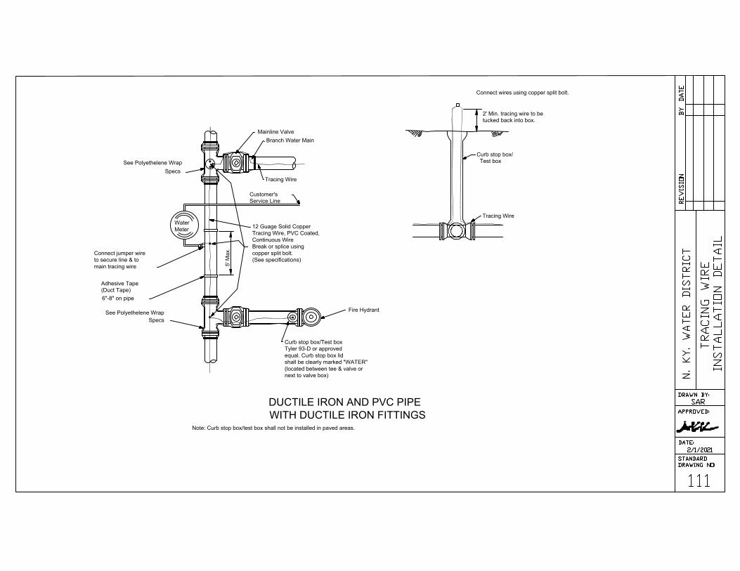
Connect wires using copper split bolt.
2' Min. tracing wire to be
tucked back into box.
Curb stop box/
Test box
Tracing Wire
Water
Meter
Mainline Valve
Branch Water Main
Tracing Wire
See Polyethelene Wrap
Specs
Customer's
Service Line
12 Guage Solid Copper
Tracing Wire, PVC Coated,
Continuous Wire
Break or splice using
copper split bolt.
(See specifications)
5' M
ax.
Connect jumper wire
to secure line & to
main tracing wire
Adhesive Tape
(Duct Tape)
6"-8" on pipe
See Polyethelene Wrap
Specs
Fire Hydrant
Curb stop box/Test box
Tyler 93-D or approved
equal. Curb stop box lid
shall be clearly marked "WATER"
(located between tee & valve or
next to valve box)
Note: Curb stop box/test box shall not be installed in paved areas.
DUCTILE IRON AND PVC PIPE
WITH DUCTILE IRON FITTINGS
AutoCAD SHX Text
111
AutoCAD SHX Text
TRACING WIRE
AutoCAD SHX Text
INSTALLATION DETAIL
AutoCAD SHX Text
REVISION
AutoCAD SHX Text
BY
AutoCAD SHX Text
DATE
AutoCAD SHX Text
N. KY. WATER DISTRICT
AutoCAD SHX Text
APPROVED:
AutoCAD SHX Text
DATE:
AutoCAD SHX Text
STANDARD
AutoCAD SHX Text
DRAWING NO:
AutoCAD SHX Text
DRAWN BY:
AutoCAD SHX Text
SAR
AutoCAD SHX Text
2/1/2021

WATER
METER
New Concrete
Slope concrete to meet
the meter lid.
Water Meter Lid.
Tooled joint around lid
Existing Crock (Performed Plastic)
New Surface
Meter
Setting
18
" M
axim
um
12
" M
in
im
um
Tooled joint around lid
of crock in concrete surface
Use a section of plastic meter
crock when the meter lid is to be
adjusted more than 6"-up to 12".
Adjustment greater than 12" will
require the meter setting and
meter crock to be raised to
meet Std. Drwg. 107.
Note: Meter lid shall be flush with the top of
the concrete surface. The concrete surface
shall be tapered to provide a smooth
transition to the meter lid. A tooled joint
shall be formed around the meter lid.
NOTE: SERVICES INSTALLED IN CONCRETE AREAS, NOT
SUBJECT TO VEHICLE TRAFFIC, A FORD TYPE A32, OR
APPROVED EQUAL, LID AND RING SHALL BE USED.
AREAS SUBJECT TO VEHICLE TRAFFIC, A FORD TYPE
A32HH, OR APPROVED EQUAL, LID AND RING SHALL BE
USED.
PLASTIC (PVC) METER CROCKS shall be raised by use of an adapter with a
section of plastic crock cut to achieve final grade.
At no time shall wood be used to adjust the ring and lid to grade.
Meter ring and lids shall be reset solidly and shall have no broken edge to allow dirt
to enter the crock.
If the meter box is damaged beyond repair it shall be replaced. See Standard
Drawing 107.
RAISING CURB STOPS OR VALVE BOXES:
Curb stop boxes and valve boxes shall be raised by turning the upper section to
meet grade. If the upper section cannot be raised in this manner it shall be
carefully broken off and replaced.
New upper sections shall be supplied by NKWD
AutoCAD SHX Text
112
AutoCAD SHX Text
ADJUDTING RING & LID
AutoCAD SHX Text
TO GRADE
AutoCAD SHX Text
REVISION
AutoCAD SHX Text
BY
AutoCAD SHX Text
DATE
AutoCAD SHX Text
N. KY. WATER DISTRICT
AutoCAD SHX Text
APPROVED:
AutoCAD SHX Text
DATE:
AutoCAD SHX Text
STANDARD
AutoCAD SHX Text
DRAWING NO:
AutoCAD SHX Text
DRAWN BY:
AutoCAD SHX Text
SAR
AutoCAD SHX Text
2/1/2021

Ring & Lid,Ford Type C-32
Ground Level
18" I.D. x24" H.
Male 2" Camlock Type
Coupling
Concrete Brick as
Required To Support
Vault.
Pea Gravel (Min. 8")
Corporation Stop **
Type "K" Copper
Double Strap Bronze
Tapping Saddle
Blow-off Piping Smaller Than
2" shall Be Increased To 2"
Camlock Type Coupling.
EXIST.
WATER
MAIN
12
" M
in
.
18
" M
ax.
No
rm
al 3
6" C
ove
r
** Taps on mains which utilizes
a cathodic protection system shall
require an isolation corporation stop
Ultra Rib Type Box
Absorption Pit
Curb Stop
Box
Curb Stop
TYPICAL FLUSHING DEVICE
INSTALLATION and Manual
Air Release Valve N.T.S.
AutoCAD SHX Text
113
AutoCAD SHX Text
REVISION
AutoCAD SHX Text
BY
AutoCAD SHX Text
DATE
AutoCAD SHX Text
N. KY. WATER DISTRICT
AutoCAD SHX Text
APPROVED:
AutoCAD SHX Text
DATE:
AutoCAD SHX Text
STANDARD
AutoCAD SHX Text
DRAWING NO:
AutoCAD SHX Text
DRAWN BY:
AutoCAD SHX Text
SAR
AutoCAD SHX Text
2/1/2021
AutoCAD SHX Text
TYPICAL FLUSHING DEVICE INSTALLATION and MANUAL RELEASE VALVE

ENCASEMENT PIPE
APPROVED PIPE
SUPPORT
CARRIER
PIPE
WELDED STEEL ENCASEMENT
PIPE ASTM A134 GRADE B.
OPEN CUT INSTALLATION WITH
SIZE AND WALL THICKNESS
AS SHOWN ON THE PLANS OR SPEC.
SEAL BOTH ENDS OF CASING PIPE
APPROVED PIPE SUPPORT
WATER MAIN
NOTE: CASING PIPE JOINTS SHALL BE SEAM WELDED SO
THAT CASING IS WATER TIGHT FROM END TO END.
NO SCALE
ENCASEMENT PIPE DETAIL
JS
2/1/00
Rem
ove G
ranular F
ill
All carrier pipe placed in steel casing pipe shall be minimum class 50 ductile iron pipe and conform
to the latest edition of AWWA C151.
Carrier pipe gaskets shall develop a wedging action between pairs of high-strength stainless
steel elements spaced around the gasket (FIELD LOK , FASTGRIP, or approved equal gaskets).
1.
2.
AutoCAD SHX Text
114
AutoCAD SHX Text
ENCASEMENT PIPE DETAIL
AutoCAD SHX Text
1.
AutoCAD SHX Text
REVISION
AutoCAD SHX Text
BY
AutoCAD SHX Text
DATE
AutoCAD SHX Text
N. KY. WATER DISTRICT
AutoCAD SHX Text
APPROVED:
AutoCAD SHX Text
DATE:
AutoCAD SHX Text
STANDARD
AutoCAD SHX Text
DRAWING NO:
AutoCAD SHX Text
DRAWN BY:
AutoCAD SHX Text
SAR
AutoCAD SHX Text
2/1/2021

R/W LINE
SEE CONNECTION
DETAIL
LOT LINE
2" C.T.S P.E. PIPE
2"X2"X1" TEE
w/1" CORP. STOP
DOUBLE STRAP BRASS SADDLE
2" BRASS NIPPLE
2" P.E. PIPE
2" STRAIGHT COUPLING
2" CURB STOP
W.M.
CONNECTION DETAIL
3'0" MIN. COVER
FINISH GRADE
EARTH
FILL
TRACING
WIRE
P.E. PIPE
COMPACTED
GRANULAR FILL
TRENCH DETAIL
Materials
Pipe-2" High Density Polyethylene Water Service Pipe,Class 200 (SDR-9),CTS-OD,200psi,
ASTM D-2737.
Tees -2"x2"x1" with Pack Joints both ends,side outlet tapped for corp stop. Ford FB 600
1" AWWA Taper Threads with Ford 1"-F600 Corporation Stop or approved equal.
materials will be provided by the Water District.
Saddles - Ford 202B Double Strap Brass Saddles (IP Threads) or approved equal.
Curb Stops - Ford 2" B11-777 Ball Valves for Iron Pipe or approved equal. A curb stop box shall
be provided.
Straight Couplings - Ford 2" C84-77 Male Iron Pipe Thread to Pack Joint type fittings for P.E. Pipe
or approved equal.
Tracing Wire- 12 gauge solid copper (P.V.C. coated) tracing wire taped to the top of the pipe
every 5'.
GENERAL INFORMATION
This detail is not designed to eliminate dead-end water mains. This is an alternate to installing 6"
or 8" pipe around a cul-de-sac.
Tees for services need to be dropped off on the opposite lot lines of the electric and other
utilities.
Tees for services will need to be properly installed with some type of above ground markers.
P.E. Pipe shall be installed after the curb are installed.
The only joints made in the P.E. pipe shall be made at the water service tees.
1" copper tubing will need to be provided for one of the water service tees for flushing purposed.
1.
2.
3.
4.
5.
6.
1.
2.
3.
4.
5.
6.
AutoCAD SHX Text
3"
AutoCAD SHX Text
1'0"
AutoCAD SHX Text
115
AutoCAD SHX Text
2" P.E. AROUND CUL-DE-SAC
AutoCAD SHX Text
REVISION
AutoCAD SHX Text
BY
AutoCAD SHX Text
DATE
AutoCAD SHX Text
N. KY. WATER DISTRICT
AutoCAD SHX Text
APPROVED:
AutoCAD SHX Text
DATE:
AutoCAD SHX Text
STANDARD
AutoCAD SHX Text
DRAWING NO:
AutoCAD SHX Text
DRAWN BY:
AutoCAD SHX Text
SAR
AutoCAD SHX Text
2/1/2021
Northern Kentucky
Water District
2021
Standard Specifications & Drawings
for the Installation of Meters Pits
S
E
R
V
I
C
E
A
T
Y
O
U
R

PIT CONSTRUCTION SPECIFICATIONS
PART I - GENERAL
1.02
1.03
1.04
1.05
1.06
1.07
1.08
1.09
1.10
1.11
1.12
INTRODUCTION Unless modified, deleted, replaced, or otherwise changed, the latest published
addition of the following documents shall be the accepted standard for materials and/or
procedures for the construction of meter pits:
1. Northern Kentucky Water District's Standard Drawings
2. Natural Resources & Environmental Protection Cabinet, Division of Water
3. Kentucky Public Service Commission Regulations
4. American Water Works Association Standards (AWWA)
If a conflict exists between referenced sources, the more restrictive requirements shall prevail.
The District shall provide interpretation as requested.
REQUIREMENTS FOR METER PIT INSTALLATION The following are guidelines for meter pit
installations:
A. Meter pit will not be required to be installed if the following conditions can be met:
Firelines-1. An approved back flow prevention device shall be installed as the first device
inside the building on the fire line before any taps or branches -and-
2. The fire department connection shall be located downstream of the approved
back flow prevention device -and-
3. The domestic water service is 2" or smaller which will be installed per Standard
Drawings #107, 107-A, or 108.
Domestic Services-- 2" or smaller domestic water services shall be installed by the District
per Standard Drawings #107, 107-A, or 108.
B. Meter pits shall be required to be installed if one or more of the following conditions exists:
Firelines-- The fire department connection is required by the authority having jurisdiction to be
installed near the public right-of-way. An approved double check assembly
shall be required to be installed per Standard Drawing #204, 206, or 207R.
Domestic Services-- 3" or larger domestic water services shall be installed per Standard
Drawings #205R, 207R, or 208.
CONTRACTORS RESPONSIBILITY All work performed on any meter pit and/or appurtenances
that are owned or anticipated to be owned by the District shall be completed under the direction of
the District adhering to an acceptable plan approved by the District. A minimum of 24 hours
notice shall be given to the District by the contractor prior to the start of work. If the interruption of
service to any customer of the District is necessary, the Contractor shall make arrangements to
provide such shutdown and notify District customers at the direction of the District Inspector.
One set of District approved plans shall be on the job site during construction. There shall be no
deviation from the approved plans without written approval from the District.
EXISTING PITS Any changes, modifications, or alterations made to an existing pit structure,
piping, etc., it shall be brought up to current standards. Compliance subject to the discretion of
the Water District.
PLANS Plans are approved subject to the conditions of compliance with all applicable laws,
rules, regulations and standards. The proposed project may be constructed only in accordance
with the approved plans. Plans submitted to the District for approval shall have a Ky. Professional
Engineer or Certified Fire Suppression Technician stamp and signature. Two sets of plans should
be submitted for preliminary review and four sets for final review.
DESCRIPTION In general the following specifications are minimum requirements as pit design.
Construction may be dictated by location, soil conditions, ground water, topography, etc.
Additional provisions may be required upon submission for approval.
ACCESSIBILITY OF PITS Accessibility for maintenance and testing of all meter pits shall be
provided. A means of access for maintenance vehicles shall be constructed of a hard, all weather
surface at least 10' wide and designed to support the heaviest vehicle, within 15' of the pit.
WATER MAINS ON PRIVATE PROPERTY Meter pits and appurtenances installed on private
property outside of normal conditions which are going to be maintained by the Water District shall
have proper documentation provided for all easement areas. See appropriate sections of
District's Standards Specifications & Drawings for the Installation of Water Mains for procedures.
HIGH PRESSURE AREAS Additional requirements may be necessary for high pressure areas
(110 psi static pressure or higher) as determined by the District.
MAINTENANCE PERIOD The Owner shall be responsible for the maintenance of the installed
meter pit and appurtenances to District Standards for a period of not less than one (1) year from
the date the meter pit is placed in service by the District. Meter pits will be placed in service when
the meter pit is 100% completed to District Standards.
MINIMUM REQUIREMENTS Floor slab shall be 6" thick concrete sloping at 1/8 inch per foot to
drain or sump location. Dimensions of slab shall be 4 inches larger all around than outside pit
walls. Pit shall be drained by a 4" drain or larger as required, leading to grade or a storm sewer.
When a drain is not practical an electric operated sump pump shall be used.
Walls shall be 8" thick concrete. Top slab shall be 8" thick reinforced concrete with #5 bars @6"
O.C. maximum, spanning in short direction and #5 bars @18" O.C. maximum, in long direction.
Two (2) #5 bars, two (2) feet long are to be placed at 45 degree to each corner of slab
openings. Reinforcing shall be placed 1-1/2" clear from the bottom of the slab or inside wall
faces. Additional reinforcement may be required.
Pit openings shall have lids as indicated or as approved in traffic areas of a type operable by a
single person. Removable aluminum ladders shall be furnished in all pits.
METER PIT DIMENSIONS Minimum inside pit dimensions shall be: Height - 5 feet; Width - 5
feet; Length - 6 feet.
AutoCAD SHX Text
REVISION
AutoCAD SHX Text
BY
AutoCAD SHX Text
DATE
AutoCAD SHX Text
N. KY. WATER DISTRICT
AutoCAD SHX Text
APPROVED:
AutoCAD SHX Text
DATE:
AutoCAD SHX Text
STANDARD
AutoCAD SHX Text
DRAWING NO:
AutoCAD SHX Text
DRAWN BY:
AutoCAD SHX Text
SAR
AutoCAD SHX Text
201
AutoCAD SHX Text
MATERIAL SPECIFICATIONS
AutoCAD SHX Text
FOR PIT CONSTRUCTION
AutoCAD SHX Text
1.01
AutoCAD SHX Text
2/1/2021

1.13 QUALITY ASSURANCE
1.14
PART 2 - PRODUCTS
2.01 MATERIALS
PART 3 - EXECUTION
3.01
PART 4 - ELECTRIC SUMP PUMPS
4.01
4.02
4.03
4.04 MATERIALS
4.05 INSTALLATION
A. Standards: The following publications shall be hereby made a part of these specifications.
1. "Specifications for Structural Concrete for Buildings ACI 301-72 (Revised 1975) with
Selected ACI and ASTM Referenced, Sp-15(73)" by the American Concrete Institute.
2. "Placing Reinforcing Bars, CRSI-WCRSI Recommended Practices" by the CRSI-WCRSI
Committee on Bar Placing.
3. "Standard Specifications for Road and Bridge Construction by the Kentucky Department
of Transportation, Bureau of Hwy. 4.Specifications for the Design and Construction Load-
Bearing Concrete Masonry by the National Concrete Masonry Association.
Or Equal All materials referenced are for design purpose only. Any other materials that are "equal"
can be used with prior approval from the District.
A. Concrete: Ready mixed type meeting K.D.O.T "Class A", 3,500 psi at 28 days compressive
strength, 4" maximum slump.
B. Reinforcing Steel: Deformed #5 bars conforming to ASTM A615, A616, or A617, grade 60.
C. Curing Compound: Acrylic based "non-residual" type meeting ASTM C309 Type 1 not less
than 18 % to cure, harden and seal concrete.
D. Lid: 48" x 54" double door, aluminum lid with locking padlock bar, centered over the meters,
Halliday Products Model #A4854 or approved equal. If padlock bar creates hazard, other locking
mechanisms maybe considered.
E. Removable Metal Ladder: Removable metal ladder shall be an approved OHSA Type 1
Industrial Heavy, 250 pound aluminum ladder. Ladder must reach from the pit floor and extend
into the pit opening. The bottom of the ladder shall be blocked to prevent it from kicking out but
still be removable.
F. Waterproofing: The exterior side of the pit walls shall be waterproofed with one coat of one
of the following materials applied in accordance with the Manufacturer's recommendations:
Thoroseal; U.S.S. Chemical Tarmastic #102; Koppers Bitumastic Super Service Black;
Damchex; Amercoat #78; or an approved equal.
Voids between pipes and chamber walls shall be grouted with a hydraulic cement such as
Waterplug or an approved equal before waterproofing pit.
G. Waterstop: A waterstop shall be provided in the pit floor to the pit walls.
H. Floor Drain: Raised or beehive dome grate, 4" minimum, similar to Wade #1634; Josam
#7324-N; or an approved equal.
I. Pit Drain Line: Cast iron, Schedule 40 PVC, Plastic STM #35 or ductile iron, 4" minimum.
J. Alternate To Pit Drain Line: Electric Submersible Sump Pump, Little Giant, Big John, Stock
#3P-639A Model #6-CIA or approved equal. Note: This alternative shall only be used when a
drain line is impractical as determined by the District. (See drawing #202 & Part 4 of Pit
Specifications)
K. Packaged, Prefab Meter Vaults: Packaged, prefab meter vaults are acceptable with
approval from the Water District.
WORKMANSHIP Earth cuts may be used for forms of base slab provided vertical sides are kept
true and sharp. All embedded items, reinforcing, piping, etc. shall be secured in place prior to
placing of the concrete. Concrete shall be protected from loss of moisture for a curing period of
at least 7 days. All concrete shall be deposited within 1-1/2 hours following the initial mixing of
water and cement. Wall finish may be a rough form finish. Top slab finish shall be wood float
with tooled edges.
DESCRIPTION In general the following specifications are a minimum requirements for the
design and installation of Electric Submersible Sump Pumps in meter pits where a normal drain
line is impractical.
ELECTRIC WORK All electric work shall be installed according to the National Electric Code
and all other applicable codes. All work shall be inspected by an Electrical Inspector and
certification provided to the District.
RESPONSIBILITY The property owner is responsible for providing continuous electric service
for the electric sump pump at the owner's expense. The property owner shall be responsible for
the maintenance and upkeep of all electrical boxes, conduit, circuit breaker box, circuit breaker,
outlet and wiring outside the pit.
A. Electric Submersible Sump Pump: Electric sump pump shall be U.L. Listed, Little
Giant, Stock #3P639, Model #6-CIA.
B. Electric Junction Box: Water resistant, U.L. Listed, P.V.C electrical box shall be installed
on the inside of the pit on the wall closest to the sump pump nearest the ceiling.
C. Electrical Piping: Electric piping shall be U.L. Listed for underground use, rigid or
plastic installed at least 18" below grade.
A. Sump Pump Hole: A 4" deep hole shall be provided in the floor of the pit.
B. Discharge Piping: Piping for the water discharge from the electric sump pump shall be
plastic or copper. Minimum piping size shall be 1 1/2". A 1/8" hole shall be bored above
the check valve of the discharge pipe if freezing temperatures will affect the pipe.
C. Water Discharge: Water discharge shall be directed into a storm sewer or drainage ditch, if
this is impractical, water discharge shall be directed on to a 16" x 16" concrete pad.
D. Electric Service Line: The electric line to the pit shall be only used for the pit sump pump,
no other electrical taps shall be made on this line.
E. Manufacturer Instructions: Manufacturer's instructions should be followed for installation.
AutoCAD SHX Text
REVISION
AutoCAD SHX Text
BY
AutoCAD SHX Text
DATE
AutoCAD SHX Text
N. KY. WATER DISTRICT
AutoCAD SHX Text
APPROVED:
AutoCAD SHX Text
DATE:
AutoCAD SHX Text
STANDARD
AutoCAD SHX Text
DRAWING NO:
AutoCAD SHX Text
DRAWN BY:
AutoCAD SHX Text
SAR
AutoCAD SHX Text
201-A
AutoCAD SHX Text
MATERIAL SPECIFICATIONS
AutoCAD SHX Text
FOR PIT CONSTRUCTION
AutoCAD SHX Text
2/1/2021
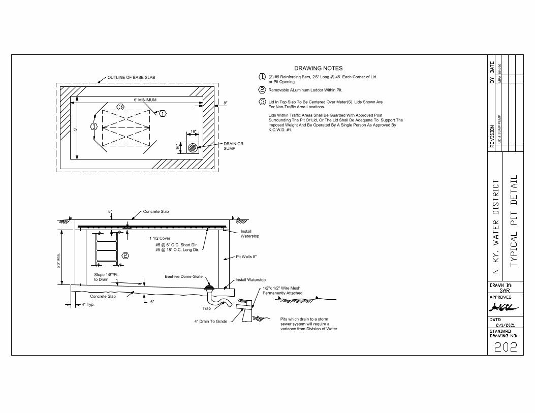
OUTLINE OF BASE SLAB
DRAIN OR
SUMP
6' MINIMUM
5'
16"
16
"
8"
Concrete Slab8"
Slope 1/8"/Ft.
to Drain
Concrete Slab
4" Typ.
5'0" M
in.
Beehive Dome Grate
1 1/2 Cover
#5 @ 6" O.C. Short Dir
#5 @ 18" O.C. Long Dir.
Install
Waterstop
Pit Walls 8"
Install Waterstop
Trap
6"
4" Drain To Grade
1/2"x 1/2" Wire Mesh
Permanently Attached
DRAWING NOTES
LID
&
S
UM
P P
UM
PM
PA
10
/4
/9
0
(2) #5 Reinforcing Bars, 2'6" Long @ 45 Each Corner of Lid
or Pit Opening.
Removable ALuminum Ladder Within Pit.
Lid In Top Slab To Be Centered Over Meter(S). Lids Shown Are
For Non-Traffic Area Locations.
Lids Within Traffic Areas Shall Be Guarded With Approved Post
Surrounding The Pit Or Lid, Or The Lid Shall Be Adequate To Support The
Imposed Weight And Be Operated By A Single Person As Approved By
K.C.W.D. #1.
Pits which drain to a storm
sewer system will require a
variance from Division of Water
AutoCAD SHX Text
1
AutoCAD SHX Text
3
AutoCAD SHX Text
1
AutoCAD SHX Text
2
AutoCAD SHX Text
1
AutoCAD SHX Text
3
AutoCAD SHX Text
2
AutoCAD SHX Text
202
AutoCAD SHX Text
TYPICAL PIT DETAIL
AutoCAD SHX Text
REVISION
AutoCAD SHX Text
BY
AutoCAD SHX Text
DATE
AutoCAD SHX Text
N. KY. WATER DISTRICT
AutoCAD SHX Text
APPROVED:
AutoCAD SHX Text
DATE:
AutoCAD SHX Text
STANDARD
AutoCAD SHX Text
DRAWING NO:
AutoCAD SHX Text
DRAWN BY:
AutoCAD SHX Text
SAR
AutoCAD SHX Text
2/1/2021

PART 1 - PRODUCTS
1.01 MATERIALS
PART 2 - EXECUTION
2.01 INSTALLATION
A. Underground Piping & Appurtenances: All underground piping and appurtenances shall
conforms to appropriate sections of District's "Standard Specifications & Drawings for the
Installation of Water Mains". All underground piping 4" and larger shall be polyethylene
wrapped Class 50 or higher Ductile Iron Pipe from the public water main to the meter pit.
B. Piping Inside Pits: Pipe installed inside the pit shall be a minimum thickness of Class 53
flanged ductile iron pipe for 3" and larger piping. The pipe shall extend through the pit walls.
C. Fittings: All fittings and accessories shall be Ductile Iron, rated for a minimum of 200 psi
working pressure or as specified herein. The fittings and accessories shall be new and
unused. (NOTE: Certain areas of the Northern Kentucky Water District require materials
used, to be of a higher working pressure than 200 psi.) All pipe fittings inside the meter pit
shall be flanged.
D. 2" and Smaller Service Branch Lines: Type K or L copper conforming to ASTM B88. Valves,
fittings, and nipples shall be brass.
E. Gate Valves 3" & Larger, Inside Pit: Conforming to AWWA Standard C509. Outside stem
and Yoke (OS&Y), ductile iron body, left hand open, resilient wedge, wheel operated, flanged
connection, gate valves. Clow Resilient Wedge Gate Valve or approved equal. Valves installed
as part of a back flow prevention assembly shall be approved by the F.C.C.C.R., U.S.C.
F. Valves 2" % Smaller: All 2" and smaller valves shall be ball valves.
G. Glands, Gaskets, Bolts & Nuts: Conforming to AWWA C111.
H. Bypass Lines on 3" & Larger Meter Lines: A bypass line of equal or one size less than the
domestic line shall be installed on all domestic meter services 3" or larger. Minimum bypass
line size is 3".
I. Meters: As purchased from Northern Kentucky Water District.
J. Pressure Reducing Valves: On domestic lines, pressure reducing valve will be required to be
installed when the static system pressures is at or above 125 psi. They will be installed before
the meter and are installed to protect the meter only. The District will not be liable for any damage
due to pressure conditions caused by or arising out of the failure or defective condition of such
pressure regulator or for damage that may occur through the installation, maintenance, or use of
such equipment. Pressure reducing valves shall be installed at least 5 pipe diameters away from
the meter. Cla-Val Model 690-48 shall be installed on 3" and larger lines. This may also include
electronic devices, sight gauge, or any other such devices per District requirements.0 thur 300
psi gauges shall be provided on the inlet and outlet sides of the pressure reducing valve.
K. Back flow Prevention Assembly: All assemblies shall be listed and approved by the Foundation
for Cross-Connection Control Research, University of Southern California (F.C.C.C.R.,U.S.C.)
and the District. The testable assembly consists of the back flow prevention unit and two
approved shut-off valves. Valves shall be full port ball valves for 2" and smaller and outside
stem and yoke, resilient wedge, left hand open, gate valves for 3" and larger. Assemblies shall
be delivered completely assembled by the original manufacturer with all components as
approved by F.C.C.C.R.,U.S.C. The assembly shall not be separated or altered in anyway.
The type of back flow prevention assembly to be installed shall be determined by the N.K.W.D.
(see Back flow Prevention Device Assembly Standard Drawings Figure II-a for general guidelines).
All approved back flow devices shall be tested and certified that it works properly after system
activation. Special permission must be obtained from the District to install a reduced pressure back
flow prevention assembly in a pit.
L. Booster Pumps: Booster pumps 3" and larger installed on water lines shall be equipped with a
Pump Suction Control Valve and/or a Low Pressure Cut-off Device which is designed to
modulate the pump discharge or shut-off the booster pump when the pressure on the suction-
side of the pump drops to 20 psi.
These devices shall be designed to prevent water hammer to the public water system. Pump
Suction Control Valve and/or a Low Pressure Cut-off Device shall be inspected and tested for
proper operation at the time of installation and at least annually thereafter. The property owner
shall maintain a complete record of all test, inspections and repairs to the devices. The devices
shall not be bypassed, made inoperative, or removed without authorization from the District.
A. Pipe Laying: Conforming to AWWA Standard C600. Maintain a minimum pipe cover of 3'-0"
with continuous pipe support for entire length. All underground piping and appurtenances shall
be installed according to appropriate sections of District's "Standard Specifications & Drawings
or the Installation of Water Mains".
B. Pit Components: Adequately supported by solid concrete blocks or supports set on the floor
slab. 2" or smaller domestic service lines may be supported by brackets mounted on the pit
wall.
C. Anchorage: Inlet valves on 3" or larger piping shall be securely anchored to the pit wall when
piping is sleeved through the wall. Additional rodding may be required at the discretion of the
District.
D. Disinfection: The interior of all surfaces in contact with the potable water system, tapping sleeve,
valves, couplings and pipe shall be swabbed with a 5 % hypochlorite solution prior to installation.
E. Valve Box Protection: The valve box over the tapping sleeve if located outside of a hard paved
area shall have a minimum 2'x2'x4" square pad cast around the lid. Refer to standard drawing
No. 105.
F. Flushing of Mains: Lines shall be flushed at a rate 2.5 ft/s.
AutoCAD SHX Text
REVISION
AutoCAD SHX Text
BY
AutoCAD SHX Text
DATE
AutoCAD SHX Text
N. KY. WATER DISTRICT
AutoCAD SHX Text
APPROVED:
AutoCAD SHX Text
DATE:
AutoCAD SHX Text
STANDARD
AutoCAD SHX Text
DRAWING NO:
AutoCAD SHX Text
DRAWN BY:
AutoCAD SHX Text
SAR
AutoCAD SHX Text
203
AutoCAD SHX Text
PIPING SPECIFICATIONS
AutoCAD SHX Text
FOR PIT CONSTRUCTION
AutoCAD SHX Text
2/1/2021

PLAN
ELEVATION
SOLID CONCRETE BLOCK SUPPORT
VALVE BOX
ASSEMBLY
3'-0" CONCRETE
PAD,5" THICK
Minimum Distance From
Street R/W To Pit
NKWD #1
Main
ISOLATING
VALVE FOR
THE PIT
6"
Min.
2'-0
" M
in
.
ST
RE
ET
R
/W
L
IN
E
6"
Min.
2'-0
" M
in
.
3'-0" M
in.
1'6
" M
in
.
DRAWING NOTES
GENERAL NOTES
An approved Double Check Valve Assembly shall be
required on Fire Lines by the following governing bodies:
Kentucky Public Service Commission, Kentucky Division of
Water, and Kentucky Division of Plumbing.
Piping Class 52 With Flanged Ends Within Pits.
Plain End Pipe By Plain End Pipe With Uniflange
Coupler In Pit
1. SEE DRAWING NO.202 FOR PIT CONSTRUCTION DETAILS
2. SEE DRAWING NO. 201 FOR PIT MATERIALS SPECIFICATIONS
3. SEE DRAWING NO. 203 FOR PIT SPECIFICATIONS
4. ANY PUMPER CONNECTION SHALL BE INSTALLED DOWNSTREAM OF
OUTLET VALVE & BACK FLOW DEVICE.
5. ANY POST INDICATOR SHALL BE TYPE THAT WILL ATTACH TO
WHEEL OPERATOR AND ALLOW OPERATION OF VALVE WITHIN PIT.
6. SHADED AREAS INDICATE WHAT THE PROPERTY OWNER WILL
MAINTAIN AFTER THE WARRANT PERIOD EXPIRES.
AutoCAD SHX Text
2
AutoCAD SHX Text
3
AutoCAD SHX Text
1
AutoCAD SHX Text
3
AutoCAD SHX Text
2
AutoCAD SHX Text
1
AutoCAD SHX Text
204
AutoCAD SHX Text
DOUBLE CHECK VALVE
AutoCAD SHX Text
SETTING FOR FIRE SYSTEM ONLY
AutoCAD SHX Text
REVISION
AutoCAD SHX Text
BY
AutoCAD SHX Text
DATE
AutoCAD SHX Text
N. KY. WATER DISTRICT
AutoCAD SHX Text
APPROVED:
AutoCAD SHX Text
DATE:
AutoCAD SHX Text
STANDARD
AutoCAD SHX Text
DRAWING NO:
AutoCAD SHX Text
DRAWN BY:
AutoCAD SHX Text
SAR
AutoCAD SHX Text
END OF DISTRICTS RESPONSIBILITY
AutoCAD SHX Text
2/1/2021

1"-6
"
Min
.
3'0
" M
in
.
ELEVATION
SOLID-CONCRETE BLOCKING SUPPORT
ROD INTO WALL
IF NECESSARY
3'0" CONCRETE
PAD
6"M
in
.
2'M
in
.
6"M
in
.
2'M
in
.2
'M
in
.
MINIMUM DISTANCE FROM
STREET R/W TO PIT
NKWD #1
MAIN
ISOLATING
VALVE FOR
THE PIT
ST
RE
ET
R
/W
L
IN
E
PLAN
DRAWING NOTES
GENERAL NOTES
CO
MP
OU
ND
M
ET
ER
,E
TC
.M
PA
10/9/90
NO
TE
4-G
EN
. N
OT
EM
PA
2/6/92
PIPING CLASS 52 WITH FLANGED END WITHIN PIT.
VALVES WITH OUTSIDE SCREW AND YOKE, FLANGED
CONNECTIONS. (RESILENT SEATED VALVES)
2.5"" OR LARGER COMPOUND METER
FLANGED COUPLING ADAPTER OVER PLAIN END PIPE
FLANGED BY PLAIN END PIPE.
STRAINER
BYPASS LINE SHALL BE EQUALIVANT IN SIZE AS THE
FEED LINE OR THE NEXT SIZE SMALLER (3" MININUM
SIZE)
If system pressures exceed 110 psi, a regulator SHALL BE
INSTALLED AS SHOWN (DWG NO. 201 item No. 1.09)
SHADED AREA DISTRICTS RESPONSIBILITY
1. SEE DRAWING 202 FOR PIT CONSTRUCTION DETAILS.
2. SEE DRAWING 201 FOR PIT MATERIALS SPECIFICATIONS.
3. SEE DRAWING 203 FOR PIPING SPECIFICATIONS.
4. An approved Double Check Valve Assembly shall be required on
Fire Lines by the following governing bodies: Kentucky Public
Service Commission, Kentucky Division of Water, and Kentucky
Division of Plumbing.
AutoCAD SHX Text
x
AutoCAD SHX Text
x
AutoCAD SHX Text
1
AutoCAD SHX Text
4
AutoCAD SHX Text
2
AutoCAD SHX Text
3
AutoCAD SHX Text
6
AutoCAD SHX Text
5
AutoCAD SHX Text
2
AutoCAD SHX Text
1
AutoCAD SHX Text
1
AutoCAD SHX Text
2
AutoCAD SHX Text
3
AutoCAD SHX Text
4
AutoCAD SHX Text
5
AutoCAD SHX Text
6
AutoCAD SHX Text
205-R
AutoCAD SHX Text
METER SETTINGS
AutoCAD SHX Text
2.5" AND LARGER
AutoCAD SHX Text
REVISION
AutoCAD SHX Text
BY
AutoCAD SHX Text
DATE
AutoCAD SHX Text
N. KY. WATER DISTRICT
AutoCAD SHX Text
APPROVED:
AutoCAD SHX Text
DATE:
AutoCAD SHX Text
STANDARD
AutoCAD SHX Text
DRAWING NO:
AutoCAD SHX Text
DRAWN BY:
AutoCAD SHX Text
SAR
AutoCAD SHX Text
7
AutoCAD SHX Text
7
AutoCAD SHX Text
END OF DISTRICTS RESPONSIBILITY
AutoCAD SHX Text
8
AutoCAD SHX Text
8
AutoCAD SHX Text
8
AutoCAD SHX Text
2/1/2021

2'-0
" M
in
.2
'-0
" M
in
.
MINIMUM DISTANCE AS REQ"D
BY WIDTH OF METER
TO THE ISOLATING
VALVE AT THE
NKWD #1 MAIN
TEE FITTING
CORPORATION STOP
(SHOWN)and/or SADDLE
(AS REQUIRED)
TYPE K COPPER
MINIMUM DISTANCE
TO R/W LINE AS
REQUIRED
PLAN
ELEVATION
SEE DRAWING 204
FOR SIMILAR DETAILS
AT TAP
SOLID CONCRETE BLOCK SUPPORTS
ST
RE
ET
R
/W
L
IN
E
3'0
" M
IN
.
DRAWING NOTES
GENERAL NOTES
7.
AD
D LO
K-P
AK
M
ET
ER
AD
D D
OU
BLE
C
HE
CK
A
SS
EM
BLY
CH
AN
GE
T
O C
US
TO
ME
R S
IT
TIN
G
MP
A
MP
S
GN
10/9/90
2/22/92
2/1/00
12
"
CURB STOP
An approved Backflow Prevention Assembly shall be
required on Fire Lines by the following governing bodies:
Kentucky Public Service Commission, Kentucky Division of
Water, and Kentucky Division of Plumbing.
REFER TO DRAWING NO.204 FOR DETAILS OF
FIRE BRANCH PIPING.
2" OR SMALLER DOMESTIC METER TO ALIGN
WITH BACK FLOW DEVICE.
VALVE
BRACKETS FOR PIPE SUPPORT.
ON 8" AND SMALLER PIPING, TAPS MADE SHALL BE
MADE WITH BRONZE SADDLE FOR 1 1/2" OR 2" TAPS.
PRESSURE REDUCING DEVICE (if pressures exceed 110 psi)
1. SEE DRAWING 202 FOR PIT CONSTRUCTION DETAILS.
2. SEE DRAWING 201 FOR PIT MATERIALS SPECIFICATIONS
3. SEE DRAWING 203 FOR PIPING SPECIFICATIONS
4. ANY PUMPER CONNECTION SHALL BE INSTALLED
DOWNSTREAM OF OUTLET VALVE & BACK FLOW DEVICE.
5. ANY POST INDICATORS SHALL BE TYPE THAT WILL
ATTACH TO WHEEL OPERATOR AND ALLOW
OPERATION OF VALVE WITHIN PIT.
6. 1 1/2" $ 2" METERS WILL COME WITH CUSTOM
SETTER.(BOTH TO BE PURCHASED FROM NKWD)
AutoCAD SHX Text
2
AutoCAD SHX Text
4
AutoCAD SHX Text
1
AutoCAD SHX Text
3
AutoCAD SHX Text
3
AutoCAD SHX Text
5
AutoCAD SHX Text
2
AutoCAD SHX Text
4
AutoCAD SHX Text
1
AutoCAD SHX Text
3
AutoCAD SHX Text
5
AutoCAD SHX Text
206
AutoCAD SHX Text
DUAL SERVICE BRANCH
AutoCAD SHX Text
SETTING WITH 2" OR 1 1/2" METERS
AutoCAD SHX Text
C
AutoCAD SHX Text
REVISION
AutoCAD SHX Text
BY
AutoCAD SHX Text
DATE
AutoCAD SHX Text
N. KY. WATER DISTRICT
AutoCAD SHX Text
APPROVED:
AutoCAD SHX Text
DATE:
AutoCAD SHX Text
STANDARD
AutoCAD SHX Text
DRAWING NO:
AutoCAD SHX Text
DRAWN BY:
AutoCAD SHX Text
SAR
AutoCAD SHX Text
6
AutoCAD SHX Text
6
AutoCAD SHX Text
2/1/2021

2'-0
" M
in
.2
'-0
" M
in
.
MINIMUM DISTANCE AS REQ"D
BY WIDTH OF METER
TO THE ISOLATING
VALVE AT THE
NKWD #1 MAIN
TEE FITTING
CORPORATION STOP
(SHOWN)and/or SADDLE
(AS REQUIRED)
TYPE K COPPER
MINIMUM DISTANCE
TO R/W LINE AS
REQUIRED
PLAN
ELEVATION
SEE DRAWING 204
FOR SIMILAR DETAILS
AT TAP
SOLID CONCRETE BLOCK SUPPORTS
ST
RE
ET
R
/W
L
IN
E
3'0
" M
IN
.
DRAWING NOTES
GENERAL NOTES
AD
D LO
K-P
AK
M
ET
ER
AD
D D
OU
BLE
C
HE
CK
A
SS
EM
BLY
MP
A
MP
S
10/9/90
2/22/92
CURB STOP
7. An approved Approved Backflow Prevention Assembly
shall be required on Fire Lines by the following governing
bodies: Kentucky Public Service Commission, Kentucky
Division of Water, and Kentucky Division of Plumbing.
REFER TO DRAWING NO.204 FOR DETAILS OF
FIRE BRANCH PIPING.
1" OR SMALLER DOMESTIC METER TO ALIGN
WITH BACKFLOW DEVICE.
VALVE
BRACKETS FOR PIPE SUPPORT.
ON 8" AND SMALLER PIPING, TAPS MADE SHALL BE
MADE WITH BRONZE SADDLE FOR 1 1/2" OR 2" TAPS.
PRESSURE REDUCING DEVICE (if pressures exceed 110 psi)
1. SEE DRAWING 202 FOR PIT CONSTRUCTION DETAILS.
2. SEE DRAWING 201 FOR PIT MATERIALS SPECIFICATIONS
3. SEE DRAWING 203 FOR PIPING SPECIFICATIONS
4. ANY PUMPER CONNECTION SHALL BE INSTALLED
DOWNSTREAM OF OUTLET VALVE & BACK FLOW DEVICE.
5. ANY POST INDICATORS SHALL BE TYPE THAT WILL
ATTACH TO WHEEL OPERATOR AND ALLOW
OPERATION OF VALVE WITHIN PIT.
6. 1" & SMALLER METERS WITH COUPLINGS TO BE
PURCHASED FROM NKWSD.
AutoCAD SHX Text
2
AutoCAD SHX Text
4
AutoCAD SHX Text
1
AutoCAD SHX Text
3
AutoCAD SHX Text
3
AutoCAD SHX Text
5
AutoCAD SHX Text
2
AutoCAD SHX Text
4
AutoCAD SHX Text
1
AutoCAD SHX Text
3
AutoCAD SHX Text
5
AutoCAD SHX Text
206-A
AutoCAD SHX Text
DUAL SERVICE BRANCH
AutoCAD SHX Text
SETTING W/1" & SMALLER METER
AutoCAD SHX Text
C
AutoCAD SHX Text
REVISION
AutoCAD SHX Text
BY
AutoCAD SHX Text
DATE
AutoCAD SHX Text
N. KY. WATER DISTRICT
AutoCAD SHX Text
APPROVED:
AutoCAD SHX Text
DATE:
AutoCAD SHX Text
STANDARD
AutoCAD SHX Text
DRAWING NO:
AutoCAD SHX Text
DRAWN BY:
AutoCAD SHX Text
SAR
AutoCAD SHX Text
6
AutoCAD SHX Text
6
AutoCAD SHX Text
2/1/2021
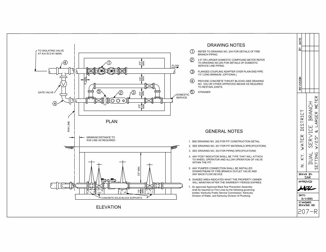
FLOW
DOMESTIC
SERVICE
TO ISOLATING VALVE
AT N.K.W.D #1 MAIN
2'0
"
MIN
.
6" M
IN
.
2'0
"
MIN
.
2'0
"
MIN
.
2'0
"
MIN
.
R/W
L
IN
E
MINIMUM DISTANCE TO
R/W LINE AS REQUIRED
3'0
" M
IN
.1
'6
"
MIN
.
CONCRETE SOLID BLOCK SUPPORTS
PLAN
ELEVATION
DRAWING NOTES
GENERAL NOTES
GATE VALVE
7. An approved Approved Back flow Prevention Assembly
shall be required on Fire Lines by the following governing
bodies: Kentucky Public Service Commission, Kentucky
Division of Water, and Kentucky Division of Plumbing.
REFER TO DRAWING NO. 204 FOR DETAILS OF FIRE
BRANCH PIPING.
2.5" OR LARGER DOMESTIC COMPOUND METER REFER
TO DRAWING NO.205 FOR DETAILS OF DOMESTIC
SERVICE LINE PIPING.
FLANGED COUPLING ADAPTER OVER PLAIN END PIPE
1'0" LONG MINIMUM. (OPTIONAL)
PROVIDE CONCRETE THRUST BLOCKS (SEE DRAWING
NO. 104) OR OTHER APPROVED MEANS AS REQUIRED
TO RESTAIN JOINTS.
STRAINER
1. SEE DRAWING NO. 202 FOR PIT CONSTRUCTION DETAIL.
2. SEE DRAWING NO. 201 FOR PIT MATERIALS SPECIFICATIONS.
3. SEE DRAWING NO. 203 FOR PIPING SPECIFICATIONS.
4. ANY POST INDICATOR SHALL BE TYPE THAT WILL ATTACH
TO WHEEL OPERATOR AND ALLOW OPERATION OF VALVE
WITHIN THE PIT.
5. ANY PUMPER CONNECTION SHALL BE INSTALLED
DOWNSTREAM OF FIRE BRANCH OUTLET VALVE AND
ANY BACK FLOW DEVICE.
6. SHADED AREA INDICATES WHAT THE PROPERTY OWNER
WILL MAINTAIN AFTER THE WARRENTY PERIOD EXPIRES.
AutoCAD SHX Text
4
AutoCAD SHX Text
1
AutoCAD SHX Text
5
AutoCAD SHX Text
2
AutoCAD SHX Text
3
AutoCAD SHX Text
4
AutoCAD SHX Text
4
AutoCAD SHX Text
1
AutoCAD SHX Text
5
AutoCAD SHX Text
2
AutoCAD SHX Text
3
AutoCAD SHX Text
207-R
AutoCAD SHX Text
DUAL SERVICE BRANCH
AutoCAD SHX Text
SETTING W/2.5" & LARGER METER
AutoCAD SHX Text
V
AutoCAD SHX Text
REVISION
AutoCAD SHX Text
BY
AutoCAD SHX Text
DATE
AutoCAD SHX Text
N. KY. WATER DISTRICT
AutoCAD SHX Text
APPROVED:
AutoCAD SHX Text
DATE:
AutoCAD SHX Text
STANDARD
AutoCAD SHX Text
DRAWING NO:
AutoCAD SHX Text
DRAWN BY:
AutoCAD SHX Text
SAR
AutoCAD SHX Text
2/1/2021

3'0" Concrete
Pad
ROD INTO WALL
IF NECESSARY
3'0
" M
IN
.
SOLID CONCRETE BLOCKING SUPPORT
NOTE: STRAINER,METER & DETECTOR CHECK VALVE SHALL
BE U.L. LISTED ASSEMBLY PURCHASED FROM
N. KY WATER DISTRICT.
MINIMUM DISTANCE FROM
STREET R/W TO THE PIT.
NKWD
MAIN
ISOLATING
VALVE FOR
THE PIT
6" M
IN
2" M
IN
2" M
IN
2" M
IN
6" M
IN
DRAWING NOTES
VALVES WITH OUTSIDE STEM AND YOKE, FLANGED
CONNECTION (RESILIENT SEATED VALVES)
U.L. FIRE RATED STRAINER
METER
U.L. LISTED DETECTOR CHECK
SPOOL PIECE, 12", FLANGED & PLAIN END
GATE VALVE
LOW FLOW METER
CHECK VALVE
BYPASS LINE SHALL BE EQUALIVANT IN SIZE AS
THE FEED LINE OR THE NEXT SIZE SMALLER (3"
MINIMUM SIZE)
CLASS 52 PIPING WITH FLANGED END WITHIN
PIT.
PRESSURE REDUCING VALVE TO BE LOCATED BEFORE
THE METER WHEN REQUIRED BY THE DISTRICT AND
AFTER THE METER WHEN REQUIRED BY THE CUSTOMER
SHADED AREA DISTRICTS RESPONSIBILITY
1. ANY PUMPER CONNECTION SHALL BE
INSTALLED DOWN STREAM OF OUTLET VALVE
& BACK FLOW DEVICE
2. ANY POST INDICATOR SHALL BE THE TYPE THAT
WILL ATTACH TO THE WHEEL OPERATOR AND
ALLOW OPERATION OF VALVE WITHIN THE PIT.
3. SEE DRAWINGS 202,201 & 203
4. An approved Approved Back flow Prevention Assembly
shall be required on Fire Lines by the following governing
bodies: Kentucky Public Service Commission, Kentucky
Division of Water, and Kentucky Division of Plumbing.
AutoCAD SHX Text
x
AutoCAD SHX Text
x
AutoCAD SHX Text
0
AutoCAD SHX Text
9
AutoCAD SHX Text
4
AutoCAD SHX Text
3
AutoCAD SHX Text
2
AutoCAD SHX Text
1
AutoCAD SHX Text
6
AutoCAD SHX Text
7
AutoCAD SHX Text
8
AutoCAD SHX Text
5
AutoCAD SHX Text
1
AutoCAD SHX Text
10
AutoCAD SHX Text
10
AutoCAD SHX Text
9
AutoCAD SHX Text
4
AutoCAD SHX Text
3
AutoCAD SHX Text
2
AutoCAD SHX Text
1
AutoCAD SHX Text
6
AutoCAD SHX Text
7
AutoCAD SHX Text
8
AutoCAD SHX Text
5
AutoCAD SHX Text
10
AutoCAD SHX Text
208
AutoCAD SHX Text
FIRE RATED METER SETTING 4"
AutoCAD SHX Text
& LARGER FOR PROPERTIES WITH
AutoCAD SHX Text
PRIVATE FIRE & DOMESTIC WATER SERVICE
AutoCAD SHX Text
11
AutoCAD SHX Text
11
AutoCAD SHX Text
REVISION
AutoCAD SHX Text
BY
AutoCAD SHX Text
DATE
AutoCAD SHX Text
N. KY. WATER DISTRICT
AutoCAD SHX Text
APPROVED:
AutoCAD SHX Text
DATE:
AutoCAD SHX Text
STANDARD
AutoCAD SHX Text
DRAWING NO:
AutoCAD SHX Text
DRAWN BY:
AutoCAD SHX Text
SAR
AutoCAD SHX Text
END OF DISTRICTS RESPONSIBILITY
AutoCAD SHX Text
12
AutoCAD SHX Text
12
AutoCAD SHX Text
12
AutoCAD SHX Text
2/1/2021

GENERAL NOTES
Hydraulic Regulator Model
690-01 Reduced Port Determined by NKWD
90-01 Full Port CALVAL
Stainless Steel Seats with o-ring
X101-Site Tube
Valve with Speed Control - To Be Determined by NKWD Stops Water Hammer
2" Low Flow-Shall have unions installed for easy removal of small
2" shall be tapped with Brass Saddle and shall be Type K copper
2" shall have Ball valves installed
Refer to drawing #202 for the Meter Vault and Drain.
Part used to identify if valve is
opened or closed
regulator-Regulator can be the same as District keeps in stock
REGULATOR w/2" Low Flow
2" Low Flow
Regulator
Regulator
See Detail
Regulator Vault
Heavy Duty
Traffic Lid
TYPE OF REGULATOR
Accessories for Hydraulic Regulator
Low Flow 2"
Regulator Vault
Pressure Guage - installed on low flow pipe between isolation valve and outlet of pressure control of P.R.V.
This should consist of isolation ball valve to pressure guage and a pressure bleed off.
Guage - 2" Tee & Ball Valve
Reduced Down to
3
4
" Guage
MINIMUM DISTANCE AS REQ"D
BY WIDTH OF REGULATOR
Resilient Seated Gate Valve
w/ rising spindle & hand wheel
Drain
Guage - 2" Tee &
Ball Valve Reduced
Down to
3
4
" Guage
Resilient Seated Gate Valve
w/ rising spindle & hand wheel
Dresser
Coupling
RSGV
Beehive Dome Grate
Trap
SOLID CONCRETE BLOCK SUPPORTS
3' M
in.
18" M
in.
w/ Rising Stem
Positive Slope
Toward Drain
All piping, valves, and fittings inside the vault shall be painted
Paint
with the exception of copper, brass, and stainless steel.
Preparation: Near-white blast cleaning or factory primed.
One coat epoxy primer.
One Coat Polyurethane enamel (blue).
**All ductile iron connections / joints inside the regulator vault
shall be flanged with the exception of the dresser coupling.
Brass Saddle Ford Type
101 BS or Equal
Corporation Stop
Ford Type F600 or
Approved Equal
Ball Valve
Regulator to be capable of reducing pressure to a range
between 75 - 150 psi
AutoCAD SHX Text
210
AutoCAD SHX Text
REGULATOR VAULTS
AutoCAD SHX Text
REVISION
AutoCAD SHX Text
BY
AutoCAD SHX Text
DATE
AutoCAD SHX Text
N. KY. WATER DISTRICT
AutoCAD SHX Text
APPROVED:
AutoCAD SHX Text
DATE:
AutoCAD SHX Text
STANDARD
AutoCAD SHX Text
DRAWING NO:
AutoCAD SHX Text
DRAWN BY:
AutoCAD SHX Text
SAR
AutoCAD SHX Text
WITH 2" LOW FLOW
AutoCAD SHX Text
2/1/2021

FLOW
DOMESTIC
SERVICE
TO ISOLATING VALVE
AT N.K.W.D #1 MAIN
2'0
"
MIN
.
6" M
IN
.
2'0
"
MIN
.
2'0
"
MIN
.
2'0
"
MIN
.
R/W
L
IN
E
MINIMUM DISTANCE TO
R/W LINE AS REQUIRED
3'0
" M
IN
.1
'6
"
MIN
.
CONCRETE SOLID BLOCK SUPPORTS
PLAN
ELEVATION
DRAWING NOTES
GENERAL NOTES
GATE VALVE
7. An approved Approved Back flow Prevention Assembly
shall be required on Fire Lines by the following governing
bodies: Kentucky Public Service Commission, Kentucky
Division of Water, and Kentucky Division of Plumbing.
REFER TO DRAWING NO. 204 FOR DETAILS OF FIRE
BRANCH PIPING.
2.5" OR LARGER DOMESTIC COMPOUND METER REFER
TO DRAWING NO.205 FOR DETAILS OF DOMESTIC
SERVICE LINE PIPING.
FLANGED COUPLING ADAPTER OVER PLAIN END PIPE
1'0" LONG MINIMUM. (OPTIONAL)
PROVIDE CONCRETE THRUST BLOCKS (SEE DRAWING
NO. 104) OR OTHER APPROVED MEANS AS REQUIRED
TO RESTAIN JOINTS.
STRAINER
1. SEE DRAWING NO. 202 FOR PIT CONSTRUCTION DETAIL.
2. SEE DRAWING NO. 201 FOR PIT MATERIALS SPECIFICATIONS.
3. SEE DRAWING NO. 203 FOR PIPING SPECIFICATIONS.
4. ANY POST INDICATOR SHALL BE TYPE THAT WILL ATTACH
TO WHEEL OPERATOR AND ALLOW OPERATION OF VALVE
WITHIN THE PIT.
5. ANY PUMPER CONNECTION SHALL BE INSTALLED
DOWNSTREAM OF FIRE BRANCH OUTLET VALVE AND
ANY BACK FLOW DEVICE.
6. SHADED AREA INDICATES WHAT THE PROPERTY OWNER
WILL MAINTAIN AFTER THE WARRENTY PERIOD EXPIRES.
CLA-VAL 90-01 or 690-01 (if system
pressure exceeds 110 psi)
AutoCAD SHX Text
4
AutoCAD SHX Text
1
AutoCAD SHX Text
5
AutoCAD SHX Text
2
AutoCAD SHX Text
3
AutoCAD SHX Text
4
AutoCAD SHX Text
4
AutoCAD SHX Text
1
AutoCAD SHX Text
5
AutoCAD SHX Text
2
AutoCAD SHX Text
3
AutoCAD SHX Text
211
AutoCAD SHX Text
DUAL SERVICE BRANCH
AutoCAD SHX Text
SETTING W/3" & LARGER METER
AutoCAD SHX Text
V
AutoCAD SHX Text
REVISION
AutoCAD SHX Text
BY
AutoCAD SHX Text
DATE
AutoCAD SHX Text
N. KY. WATER DISTRICT
AutoCAD SHX Text
APPROVED:
AutoCAD SHX Text
DATE:
AutoCAD SHX Text
STANDARD
AutoCAD SHX Text
DRAWING NO:
AutoCAD SHX Text
DRAWN BY:
AutoCAD SHX Text
SAR
AutoCAD SHX Text
6
AutoCAD SHX Text
6
AutoCAD SHX Text
2/1/2021