
NORTH BUS DEPOT BASIS OF DESIGN REPORT - …newla.co.za/uploads/897.pdf · NORTH BUS DEPOT BASIS OF...
42
PS‐PT 38/2013 CONTRACT 1 PHASE 1A AND PHASE 1B OF THE INTEGRATED RAPID PUBLIC TRANSPORT NETWORK (IRPTN) NORTH/SOUTH CORRIDOR PROFESSIONAL SERVICES NORTH BUS DEPOT BASIS OF DESIGN REPORT 8 May 2015 Prepared by: UWP/SMEC South Africa JV DOCUMENT No. PS‐PT38/2013/1/RFA/043 Rev Date Preparation Review Work Stream Approved JV Approved EMM Description of Revision (Responsible Person) (Accountable Person) 0 4/05/2015 Marius Mostert Zulch Lötter Final report 1 8/05/2015 Marius Mostert Zulch Lötter Comments incorporated THIS DOCUMENT IS THE PROPERTY OF THE CITY OF EKURHULENI AND CANNOT BE USED, REPRODUCED, TRANSMITTED AND/OR DISCLOSED WITHOUT PRIOR WRITTEN PERMISSION
Transcript of NORTH BUS DEPOT BASIS OF DESIGN REPORT - …newla.co.za/uploads/897.pdf · NORTH BUS DEPOT BASIS OF...

PS‐PT 38/2013
CONTRACT 1
PHASE 1A AND PHASE 1B OF THE
INTEGRATED RAPID PUBLIC TRANSPORT NETWORK (IRPTN)
NORTH/SOUTH CORRIDOR
PROFESSIONAL SERVICES
NORTH BUS DEPOT
BASIS OF DESIGN REPORT
8 May 2015
Prepared by:
UWP/SMEC South Africa JV
DOCUMENT No. PS‐PT38/2013/1/RFA/043
Rev Date
Preparation Review Work
Stream Approved JV
Approved EMM
Description of Revision (Responsible
Person) (Accountable
Person)
0 4/05/2015 Marius Mostert Zulch Lötter Final report
1 8/05/2015 Marius Mostert Zulch Lötter Comments incorporated
THIS DOCUMENT IS THE PROPERTY OF THE CITY OF EKURHULENI AND CANNOT BE USED, REPRODUCED, TRANSMITTED AND/OR DISCLOSED WITHOUT PRIOR WRITTEN PERMISSION
UWP / SMEC South Africa JV CoE IRPTN – Bus Depot – Basis of design Project Management Report
2015/05/08 (i)
EXECUTIVE SUMMARY
UWP / SMEC South Africa JV has been appointed by the EMM to design the phase 1A and
1B of the IRPTN. The design of the Tembisa Bus Depot forms part of this appointment. This
report deals with the basis of design for the bus depot. The depot will provide administration
functions for the northern trunk route; inspect fuel and washing services for 162 buses.
Parking will be provided for 103 buses on the site. The remainder of the buses will be parked
off site. The Client has identified various alternative parking options, but at the time of the
report were not finalized and will not be part of this design appointment. This facility will
service 162 buses from this depot as well as the 26 buses from the southern bus station.
There will be 9m feeder, 12m standard and 18m articulated buses at the facility.
This appointment will terminate at the end of June 2015. The design team have to develop
the design up to Stage 4. This includes all construction information from the various
disciplines as well as the tender document. The aim of this “Basis of Design” approval is to
fix the design parameters and freeze the layouts (Stage 3 approval) prior to starting with the
construction documentation and tender document. The team will require this approval by the
4th of May 2015 in order for the team to meet the tight Stage 4 deadline. This report may
also be used in future to convey the design approach and parameters to the implementing
consulting team and to the Operator.
This report deals with the baseline information used in the design as well as the design
approach. The baseline information includes the site survey, geotechnical report, bus tender
specifications, bus movements at the depot and the operational information obtained from
Pegasus. The design approach for the Depot is based on a best practise approach review of
other similar facilities. The team visited the latest operational BRT Bus station in Dobsonville
and equipment suppliers to establish the best practise approach.
This report gives an overview of the basis of design approach for the depot for all the project
disciplines from a Project Management perspective. The project disciplines that were
involved in this phase of the project are Architectural, Civil, Electrical, ITS, Mechanical,
Structural Engineering and Landscape Architecture. This report also highlights the discipline
specific design approaches that were followed.

UWP / SMEC South Africa JV CoE IRPTN – Bus Depot – Basis of design Project Management Report
2015/05/08 (ii)
TABLE OF CONTENTS
Page No.
1. GENERAL................................................................................................................. 1
1.1 Introduction ............................................................................................................... 1
1.2 Site Location ............................................................................................................. 2
1.3 Geographical characteristics of the site .................................................................... 2
1.4 Land rights, existing zoning and ownership .............................................................. 3
1.5 Servitudes and other restrictions ............................................................................... 3
1.6 Scope of the Work..................................................................................................... 3
1.7 Time management .................................................................................................... 3
2. PROJECT INPUT AND COMMUNICATION ............................................................ 4
2.1 Baseline Information Provided .................................................................................. 4
2.2 Depot design team .................................................................................................... 5
2.3 Request for Information (RFI) ................................................................................... 6
2.4 Client and Project technical team coordination meetings ......................................... 6
3. DEPOT OPERATIONAL REQUIREMENTS ............................................................. 7
3.1 Future operator assumptions .................................................................................... 7
3.2 Bus vehicle movements at the depot ........................................................................ 7
3.3 Depot staff numbers and working hours ................................................................... 8
3.4 Bus driver numbers, working hours and habits ......................................................... 9
3.5 Gender ratios for various Depot functions ................................................................. 9
3.6 Bus and vehicle parking requirements .................................................................... 10
3.7 Depot ITS system approach.................................................................................... 10
4. ADMINISTRATION BUILDING DESIGN REQUIREMENTS .................................. 12
4.1 Office functions ....................................................................................................... 12
4.2 Facilities for the drivers ........................................................................................... 12
5. MAINTENANCE BUILDING DESIGN REQUIREMENTS ...................................... 13
5.1 Maintenance requirements...................................................................................... 13
5.2 Service area design requirements .......................................................................... 14
5.3 General maintenance area design requirements .................................................... 15
5.4 Centralized lubrication system – oil store and dispensing ...................................... 15
5.5 Centralized compressed air system – compressor room and reticulation ............... 16
5.6 Maintenance service utilities stands ........................................................................ 17
5.7 Maintenance supply stores ..................................................................................... 17
5.8 Flammable liquid stores .......................................................................................... 18

UWP / SMEC South Africa JV CoE IRPTN – Bus Depot – Basis of design Project Management Report
2015/05/08 (iii)
5.9 Spray booth requirements ....................................................................................... 18
5.10 General design aspects .......................................................................................... 19
6. SITE DESIGN REQUIREMENTS ........................................................................... 19
6.1 Bus gatehouse ........................................................................................................ 19
6.2 Fuel tanks ............................................................................................................... 20
6.3 Refuelling and inspection bays ............................................................................... 20
6.4 Dry internal cleaning and washing bay ................................................................... 21
6.5 Bus parking area ..................................................................................................... 22
6.6 Staff parking area .................................................................................................... 22
6.7 Basement water tanks and pump installations ........................................................ 23
6.8 Mini soccer / attenuation pond design approach ..................................................... 23
7. ARCHITECTURAL OVERVIEW OF THE DESIGN ................................................ 24
8. CIVIL ENGINEERING OVERVIEW ........................................................................ 24
8.1 Bulk Earthworks: ..................................................................................................... 24
8.2 Roads and handstands: .......................................................................................... 24
8.3 Storm water drainage design: ................................................................................. 25
8.4 Water supply: .......................................................................................................... 25
8.5 Rain water harvesting and wash water re-cycling plant: ......................................... 25
9. ELECTRICAL SYSTEMS OVERVIEW ................................................................... 25
9.1 MAIN ELECTRICAL RETICULATION ..................................................................... 25
9.2 POWER DISTRIBUTION ........................................................................................ 26
9.3 LIGHTING ............................................................................................................... 26
9.4 SMALL POWER ...................................................................................................... 26
10. STRUCTURAL ENGINEERING ............................................................................. 27
10.1 Site Founding Conditions ........................................................................................ 27
10.2 Building Envelope Structures .................................................................................. 28
10.3 Basement Parking ................................................................................................... 28
10.4 Maintenance Building .............................................................................................. 28
10.5 Administration Building............................................................................................ 28
10.6 Training Building ..................................................................................................... 28
10.7 Refuelling Building .................................................................................................. 29
10.8 Wash Bay Building .................................................................................................. 29
10.9 Gate House ............................................................................................................. 29
10.10 Parking Hard Stands and circulation drive ways ..................................................... 29
11. MECHANICAL SYSTEMS OVERVIEW ................................................................. 29

UWP / SMEC South Africa JV CoE IRPTN – Bus Depot – Basis of design Project Management Report
2015/05/08 (iv)
11.1 Heating, Ventilation & Air-conditioning (HVAC) ...................................................... 29
11.2 Domestic Potable Water ......................................................................................... 30
11.3 Fire Protection ......................................................................................................... 30
11.4 Compressed Air ...................................................................................................... 31
11.5 Lifts ......................................................................................................................... 31
11.6 Specialised Mechanical Systems ............................................................................ 31
12. ITS SYSTEMS OVERVIEW .................................................................................... 31
12.1 Gatehouse .............................................................................................................. 31
12.2 Refuelling ................................................................................................................ 32
12.3 Bus inspection/bus washing .................................................................................... 33
12.4 Bus depot parking ................................................................................................... 33
12.5 Maintenance building .............................................................................................. 34
12.6 Admin building ........................................................................................................ 34
12.7 Training Building ..................................................................................................... 35
12.8 Public/Staff Entrance............................................................................................... 35
12.9 Conduits, cable tray, sleeves and manhole ............................................................ 35
12.10 Power supply, reticulation and backup power requirements ................................... 35
12.11 Cooling requirements .............................................................................................. 36
12.12 Perimeter/boundary wall security ............................................................................ 36
TABLE OF FIGURES
Figure 1: Site Location ............................................................................................................ 2
TABLE OF TABLES
Table 1: Geographical Characteristics of the Site ................................................................... 3
ABBREVIATIONS EMM IRPTN
City of Ekurhuleni Integrated Rapid Public Transport Network
UWP SMEC
UWP (Pty) Ltd SMEC SA (Pty) Ltd
ARG ARG Architects SANS South African National Standards et al. et ali etc. et cetera i.a. inter alia i.c. in casu

UWP / SMEC South Africa JV CoE IRPTN – Bus Depot – Basis of design Project Management Report
2015/05/08 (v)
i.d. Idem i.e. id est i.f. in fine kPa Kilopascals MPa Megapascals

UWP / SMEC South Africa JV CoE IRPTN – Bus Depot – Basis of design Project Management Report
2015/05/08 1
1. GENERAL
1.1 Introduction
UWP / SMEC South Africa JV has been appointed by the EMM to design the phase
1A and 1B of the IRPTN. The design of the Tembisa Bus Depot forms part of this
appointment. This report deals with the basis of design for the bus depot. The depot
will provide administration functions for the northern trunk route, inspect, fuel and
washing services for 162 buses. Parking will be provided for 103 buses on the site.
The remainder of the buses will be parked elsewhere. The Client has identified
various alternative parking options, but at the time of the report were not finalized
and will not be part of this design appointment. This facility will service 162 buses
from this depot as well as the 26 buses from the southern bus station. There will be
9m feeder, 12m standard and 18m articulated buses at the facility.
This appointment will terminate at the end of June 2015. The design team has to
develop the design up to Stage 4. This includes all construction information from the
various disciplines as well as the tender document. The aim of this “Basis of
Design” approval is to fix the design parameters and freeze the layouts (Stage 3
approval) prior to starting with the construction documentation and tender
document. The team will require this approval by the 4th of May 2015 in order for the
team to meet the tight Stage 4 deadline. This report may also be used in future to
convey the design approach and parameters to the implementing consulting team
and to the Operator.
This report deals with the baseline information used in the design as well as the
design approach. The baseline information includes the site survey, geotechnical
report, bus tender specifications, bus movements at the depot and the operational
information obtained from Pegasus. The design approach for the Depot is based on
a best practise approach review of other similar facilities. The team visited the new
BRT Bus station in Dobsonville and interviewed the COO, Javier Cajiao. His input
was valuable to understand the operation of the depot, the staff requirements, the
maintenance philosophy and the design requirements. He also pointed out the
design flaws and pitfalls in the current design. The team also met with garage
equipment specialists and spray booth specialists to get their design input.
This report outlines the operational assumptions that were made in order to design
the various aspects of the facility. It also describes the assumptions and motivation

UWP / SMEC South Africa JV CoE IRPTN – Bus Depot – Basis of design Project Management Report
2015/05/08 2
for the design solutions. This report also highlights the discipline specific design
approaches that were followed.
1.2 Site Location
The proposed site for the Tembisa Depot is situated south of Nakuru Street in
Tembisa, Ekurhuleni in the Gauteng province of South Africa. Figure 1 below
displays the position of the site relative to its surroundings.
1.3 Geographical characteristics of the site
The attached Table 1 summarizes the geographical characteristics of the site. The
site covers an area of 3.5 hectares.
Site Characteristic Unit Value Site Characteristic Unit Value
Latitude [° ‘ “] 26° 01’ 53.40” Longitude [° ‘ “] 28° 11’ 48.30”
Figure 1: Site Location

UWP / SMEC South Africa JV CoE IRPTN – Bus Depot – Basis of design Project Management Report
2015/05/08 3
Altitude (AMSL) [m] 1 594 Mean Annual
Precipitation [mm] 723
Mean 24 Hour
Maximum
Precipitation
[mm] 55.6
Mean Thunder
Storm Days per
Annum
[pa] 72
1.4 Land rights, existing zoning and ownership
The EMM has recently purchased the existing depot facility. The site is currently
zoned for “Residential 2” and will be rezoned for “Transportation” use. The rezoning
process is expected to be completed by 30 June 2015. The Client is managing this
process.
1.5 Servitudes and other restrictions
The design team is not aware of any servitude or other restrictions on the site. The
Client is in the process of removing restriction on the site as part of the rezoning
process. The details of the previous restrictions were not known.
1.6 Scope of the Work
The scope of this appointment is to develop the brief for the facility and to develop
the design into Stage 4 documentation. This will include the Architectural, Civil,
Structural, Electrical, Mechanical, Fire and Landscape Architecture construction
documentation for the facility. The QS will compile the tender document and Bill of
Quantities for the facility. This appointment will end on the 30th of June 2015. The
above information will be presented to the Client on the 1st of July 2015.
The Depot facility consists of the Administration building, the Maintenance building
with a basement parking structure, private vehicle parking area, bus entrance,
inspections pits, refuelling area, wash bays, bus parking area and training area.
1.7 Time management
UWP / SMEC JV is responsible for the time management of the design phase of the
project. The depot design stage 3 documentation is presented in this report.
The Construction documentation and tender document (Stage 4) must be submitted
to the Client on the 1st of July 2015. The JV will notify the Client of a potential
program slip as soon as a delay manifests itself.
Table 1: Geographical Characteristics of the Site

UWP / SMEC South Africa JV CoE IRPTN – Bus Depot – Basis of design Project Management Report
2015/05/08 4
2. PROJECT INPUT AND COMMUNICATION
2.1 Baseline Information Provided
The following baseline information was used in the design of the Depot. Table 2 list
the various disciplines, the company involved and their input in the design phase of
the project;
Discipline Company Design input
Land
Surveyor Provided a survey for the site.
Fire Engineer SFT
Fire engineer met with the team and provided the design
input. Final Rational fire design report to be submitted
before 30 June 2015.
Traffic
modelling Transportfutures
Provided the bus numbers including the spares. Also
provided the bus movements at the depot facility.
Bus
specifications Aurecon
Provided the tender bus specifications document to the
design team.
Traffic
Engineer UWP/SMEC Compiled the traffic study for the entrance to the Depot
Geotechnical
Engineer SMEC
Provided the Geotechnical investigation for the site with
foundation recommendations and comments on the use
of in-situ material for the roads and hardstands.
OHS Not available OHS aspects not addressed in this phase of the project.
EIA NLA – part of UWP/SMEC JV
The EIA assessment of certain aspects of the design
including the fuel tanks and the site storm water
management plan.
Green
Building
Consultant
Not required Not required by Client. The team will comply with the
new SANS 10400 as well as a best practise approach.
Operator Javier Cajiao – COO Rea Vaya
Dobsonville depot
Operational structure, critical review of current
Dobsonville Depot facility, staff working hours input,
operational ratios and requirements. Independent design

UWP / SMEC South Africa JV CoE IRPTN – Bus Depot – Basis of design Project Management Report
2015/05/08 5
review.
Spray booth Zenith
Local fabricator of bus / truck spray booths. Provided
input on preparation bay, spray booth, paint mixing area,
electrical demand, air handling and fire requirements.
Garage
equipment
Garage Equipment Supplies
Input on the latest garage equipment trends and
specialist equipment including the centralized lubrication
system, pits, lift, break tester, pneumatic systems, waste
oil handling, tyre changing, tyre balancing and
mechanical parts washing.
Fuel tanks Neda Consulting
Design of the underground fuel tanks, piping and
pumping diagrams, Environmental requirements and fire
risk assessment.
2.2 Depot design team
The depot design team consists of the following Professional disciplines:
Discipline Company
Architect ARG Architects / Holm Jordaan JV
Project Manager SMEC
Civil Engineer SMEC
Structural Engineer SMEC
Electrical Engineer SMEC
Mechanical Engineer SMEC
ITS & Electronic Engineer Techso
Quantity Surveyor LDM
Landscape Architect NLA
Table 2: Baseline information used in the design

UWP / SMEC South Africa JV CoE IRPTN – Bus Depot – Basis of design Project Management Report
2015/05/08 6
2.3 Request for Information (RFI)
Information was requested from the City of Ekurhuleni and the various disciplines in
the form of Request for Information (RFI) schedules that were compiled by the
team. A copy of the final RFI is attached in the overall Request for approval (RFA)
document in appendix F. The RFI schedule indicates who raised a query and who
answered the query and on what date. The technical queries pertaining to the
operational requirements for the depot could not be answered by the EMM. These
queries were answered through site visits and interviews with industry specific
specialists based on the current best practise approach. The intent of the team was
to provide a flexible solution for the future operator. The aim of this document is to
outline the design approach that the team followed for each aspect of the design
and to convey it to the Client and the future operator.
2.4 Client and Project technical team coordination meetings
All communication with the Client was channelled through the UWP / SMEC JV
overall PM, Zulch Lotter. The design team held design coordination Video
Conference meetings on a weekly basis. Separate operational and supplier visits
were scheduled and attended by the discipline specific team members. A design
workshop was held on the 15th of April 2015 to finalize the design concepts and
layout plans. The design development plans and this basis of design report and
supporting documentation are presented to the Client on the 4th of May 2015. The
signing of this Request for Approval (RFA) pack will constitute the record of
decision for the Depot design assumptions and parameters. All the supporting
information will be shared with Brentt Mossick who is acting as the technical advisor
to the Client from the PWU team.
Table 3: Depot Professional team composition

UWP / SMEC South Africa JV CoE IRPTN – Bus Depot – Basis of design Project Management Report
2015/05/08 7
3. DEPOT OPERATIONAL REQUIREMENTS
3.1 Future operator assumptions
The facility has been designed based on one operator operating from the
administration building and this facility. This affects the number of dispatchers,
unions and office staff. The number of managers depends on the operational
structure of the Bus Operating Company (BOC). We have based the office staff
numbers on the staff ratios obtained from our visit to the Dobsonville Depot. The
offices are open plan to allow for future space planning requirements. The number
of individual offices has been limited to the top management structure at the depot.
3.2 Bus vehicle movements at the depot
The design of the facility is based on the number of buses at the facility and the
expected vehicle movements. The vehicle movements at the Depot facility were
provided by Transportfutures and are summarized below:
1 2 3 4 5 6 7 8 9 10 11 12 13 14 15 16 17
Bus movements along Nakuru Street ‐ and in / out Depot 05:00 06:00 07:00 08:00 09:00 10:00 11:00 12:00 13:00 14:00 15:00 16:00 17:00 18:00 19:00 20:00 21:00
06:00 07:00 08:00 09:00 10:00 11:00 12:00 13:00 14:00 15:00 16:00 17:00 18:00 19:00 20:00 21:00 22:00
Exit
depot
Return
Depot
Return
Depot
Comp 12m (STD) 12m 80 40 20 20 40 60 20
Trunk 18m (ARTIC) 18m 19 6 5 2 9 11 8
Feeder 12m (STD) 12m 18 12 6 6 12 6
16 11 5 6 11 5
FEEDER F5 12m Nakuru St (N'bound) Andrew Mapheto Dr to Brian Mazibuko Dr 3 7 7 7 4 4 4 4 4 4 7 7 7 7 4 4 4
Nakuru St (S'bound) Brian Mazibuko Dr to Andrew Mapheto Dr 3 7 7 7 4 4 4 4 4 4 7 7 7 7 4 4 4
Buses In depot at end of hour 05:00 06:00 07:00 08:00 09:00 10:00 11:00 12:00 13:00 14:00 15:00 16:00 17:00 18:00 19:00 20:00 21:00 22:00
Comp 12m (STD) 88 8 8 8 48 68 68 68 68 68 48 8 8 8 68 68 68 88
Trunk 18m (ARTIC) 21 2 2 2 8 13 13 13 13 13 11 2 2 2 13 13 13 21
Feeder 12m (STD) 38 4 4 4 4 27 27 27 27 27 16 4 4 4 27 27 27 38
Fleet total that use Tembisa Depot 147
On road 0 133 133 133 87 39 39 39 39 39 72 133 133 133 39 39 39 0
Busses in depot 147 14 14 14 60 108 108 108 108 108 75 14 14 14 108 108 108 147
Total = 147 147 147 147 147 147 147 147 147 147 147 147 147 147 147 147 147 147
Vehicle exit / return 0 133 0 0 46 48 0 0 0 0 33 61 0 0 94 0 0 39
Return Depot Exit Depot
Depot ‐ Nakura St ‐ Andrew Mapheto Dr
Depot ‐ Nakura St ‐ Andrew Mapheto Dr
Depot ‐ Nakura St ‐ Andrew Mapheto Dr
Depot ‐ Nakura St ‐ Brian Mazibuko Dr
The vehicle movement numbers provided are based on the 12 and 18m buses. The
bus numbers will change when the 9m feeder buses are introduced and were not
available at the time of this report. This may result in a slight variation in the bus
driver numbers due to increase in the total number of buses from 147 to 162. The
facility design should be able to accommodate the slight variation. Additional bus
parking will have to be provided off site.
There is an allowance for 10% spare capacity in the bus numbers. The spare
capacity buses will be rotated in the fleet to ensure that the average kilometres on
the buses are kept similar. This will be done to maintain the same depreciation on
the vehicles. The 12m buses are typically operated until 750,000 km and the 18m
articulated buses are operated until 675,000 km. The buses are replaced after
approximately 12 years.
UWP / SMEC South Africa JV CoE IRPTN – Bus Depot – Basis of design Project Management Report
2015/05/08 8
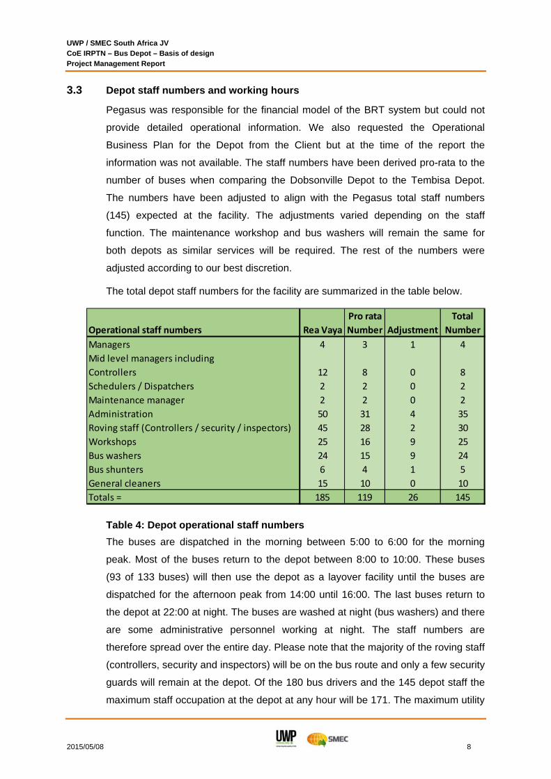
3.3 Depot staff numbers and working hours
Pegasus was responsible for the financial model of the BRT system but could not
provide detailed operational information. We also requested the Operational
Business Plan for the Depot from the Client but at the time of the report the
information was not available. The staff numbers have been derived pro-rata to the
number of buses when comparing the Dobsonville Depot to the Tembisa Depot.
The numbers have been adjusted to align with the Pegasus total staff numbers
(145) expected at the facility. The adjustments varied depending on the staff
function. The maintenance workshop and bus washers will remain the same for
both depots as similar services will be required. The rest of the numbers were
adjusted according to our best discretion.
The total depot staff numbers for the facility are summarized in the table below.
Pro rata Total
Operational staff numbers Rea Vaya Number Adjustment Number
Managers 4 3 1 4
Mid level managers including
Controllers 12 8 0 8
Schedulers / Dispatchers 2 2 0 2
Maintenance manager 2 2 0 2
Administration 50 31 4 35
Roving staff (Controllers / security / inspectors) 45 28 2 30
Workshops 25 16 9 25
Bus washers 24 15 9 24
Bus shunters 6 4 1 5
General cleaners 15 10 0 10
Totals = 185 119 26 145
The buses are dispatched in the morning between 5:00 to 6:00 for the morning
peak. Most of the buses return to the depot between 8:00 to 10:00. These buses
(93 of 133 buses) will then use the depot as a layover facility until the buses are
dispatched for the afternoon peak from 14:00 until 16:00. The last buses return to
the depot at 22:00 at night. The buses are washed at night (bus washers) and there
are some administrative personnel working at night. The staff numbers are
therefore spread over the entire day. Please note that the majority of the roving staff
(controllers, security and inspectors) will be on the bus route and only a few security
guards will remain at the depot. Of the 180 bus drivers and the 145 depot staff the
maximum staff occupation at the depot at any hour will be 171. The maximum utility
Table 4: Depot operational staff numbers

UWP / SMEC South Africa JV CoE IRPTN – Bus Depot – Basis of design Project Management Report
2015/05/08 9
demand will be based on this maximum occupation number. Refer to the attached
table that indicates the expected staff levels for every hour of the day:
1 2 3 4 5 6 7 8 9 10 11 12 13 14 15 16 17 18 19 20 21 22 23 24
Max 00:00 01:00 02:00 03:00 04:00 05:00 06:00 07:00 08:00 09:00 10:00 11:00 12:00 13:00 14:00 15:00 16:00 17:00 18:00 19:00 20:00 21:00 22:00 23:00
p/d Staff description 01:00 02:00 03:00 04:00 05:00 06:00 07:00 08:00 09:00 10:00 11:00 12:00 13:00 14:00 15:00 16:00 17:00 18:00 19:00 20:00 21:00 22:00 23:00 00:00
180 Drivers at the depot 0 0 0 0 0 133 4 4 50 98 98 98 98 98 65 4 4 4 52 4 4 43 0 0
4 Managers 0 0 0 0 0 1 1 2 4 4 4 4 4 4 4 4 4 4 4 2 1 1 0 0
8 Controllers 0 0 0 0 4 4 4 4 4 4 4 4 4 4 4 4 4 4 4 4 4 4 4 0
2 Schedulers / Dispatchers 0 0 0 0 1 1 1 1 1 1 1 1 1 1 1 1 1 1 1 1 1 1 1 0
2 Maintenance manager 0 0 0 0 0 0 0 1 2 2 2 2 2 2 2 2 2 1 0 0 0 0 0 0
35 Administration 8 8 8 8 10 2 2 25 25 25 25 25 23 23 25 25 25 2 2 2 2 2 8 8
30 Roving (Controllers / secu 6 6 6 6 6 16 6 6 6 6 6 6 6 6 6 6 6 6 6 6 6 6 6 6
25 Workshops 0 0 0 0 0 0 0 25 25 25 25 25 25 25 25 25 25 0 0 0 0 0 0 0
24 Bus washers 24 24 24 24 0 0 0 0 0 0 0 0 0 0 0 0 0 0 0 0 24 24 24 24
5 Bus shunters 5 5 2 2 0 0 0 0 0 0 0 0 0 0 0 0 0 0 3 3 5 5 5 5
10 General cleaners 4 4 4 4 4 0 0 6 6 6 6 6 6 6 6 6 6 0 0 4 4 4 4 4
47 47 44 44 25 157 18 74 123 171 171 171 169 169 138 77 77 22 72 26 51 90 52 47Total head count @ depot p/h
Operational time slots
Drivers
Operation
3.4 Bus driver numbers, working hours and habits
The bus drivers work 45 hours a week for 6 days of the week. On a typical day the
9 working hours per day may be staged over a 14 hour period. There are relief
points along the route where drivers swap over or change shifts by the roving
controllers. This reduces the number of bus drivers to be employed. On any given
day the bus service is provided over a 15 hour period from 5:00 until 22:00 at night.
In the off peak period there are only 39 buses operating from 10:00 until 14:00 and
from 18:00 until 22:00. The number of bus drivers has been based on the vehicle
movement numbers, assuming that there will be 4 standby drivers at the facility at
any time. The maximum number of drivers utilized on a day will amount to 176. The
total number of drivers employed at the Tembisa facility (240) is based
proportionally on the Dobsonville depot drivers to bus ratio.
3.5 Gender ratios for various Depot functions
The Gender ratios for the various functions vary and have been considered in the
design of the facility. The numbers provided are based on the gender ratios that we
obtained from the Dobsonville Depot visit and may vary depending on the final
operational plan for the facility. The drivers are predominantly 97% male and only
3% female. The Administration staff is 60% female and 40% male. The
maintenance workshop is 75% female and 25% male. The washing staff is 80%
female and 20% male. The Female staff is generally better with detail work. At the
Dobsonville depot their approach is to employ husband and wife in an effort to
reduce the number of strikes.
Table 5: Hourly Depot and driver staff numbers
UWP / SMEC South Africa JV CoE IRPTN – Bus Depot – Basis of design Project Management Report
2015/05/08 10
3.6 Bus and vehicle parking requirements
Based on the Dobsonville Depot visit the Tembisa Depot should be situated on a
5.5 ha site to accommodate the number of buses. The allocated site is only 3.5 ha
and there is only parking for 103 buses on the site. The remainder of the buses will
be parked off site at another facility. At the time of this report the Client engaged
with other land owners in the vicinity but an agreement has not been finalized. This
spill over facility design will fall outside the scope of this appointment.
The private vehicle parking will be based on the Ekurhuleni town planning scheme
requirements. Based on this a total of 144 parking bays will be required. The
operator should implement a staff transport policy to collect and deliver the bus
drivers from their homes to the Depot. This transport is provided by external taxis
and reduces the parking demand at the depot.
Some of the drivers prefer to use their own transport and this percentage change
over time. Initially, at Dobsonville only 15% of the staff used their own transport.
This number has escalated to 55% currently. The number of drivers using their own
transport also varies throughout the month. The highest numbers are recorded in
the week after payday. Thereafter, the numbers reduce and the staff makes use of
the staff transport facility.
The parking at the Tembisa Depot will be provided both on grade and in the
basement structure. The basement structure was required due to the limited space
on the site. The Client and the Dobsonville operator advised us to supply additional
parking bays. This will be investigated in the detail design.
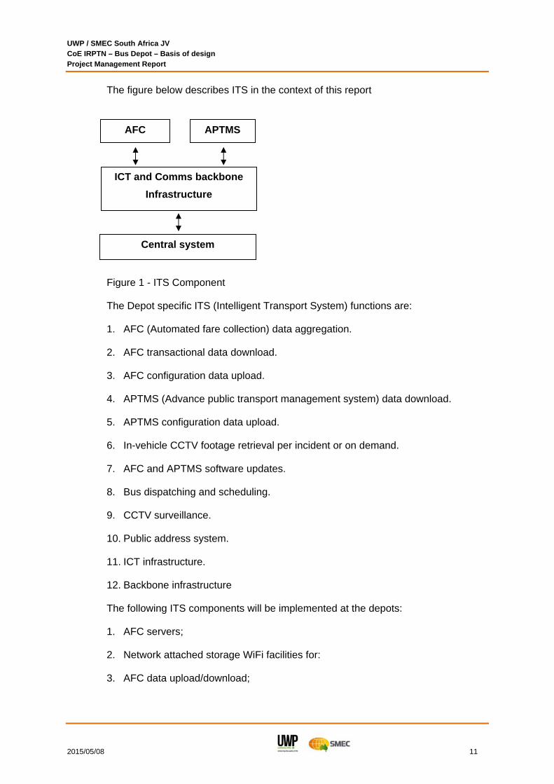
3.7 Depot ITS system approach
The ITS systems for the depot use information and communication technologies to
make the transportation system safe, efficient and reliable. The EMM IRPTN bus
depot requires Intelligent Transport System (ITS) subsystems to be installed at the
depot which tie back to the central system.
UWP / SMEC South Africa JV CoE IRPTN – Bus Depot – Basis of design Project Management Report
2015/05/08 11
The figure below describes ITS in the context of this report
Figure 1 - ITS Component
The Depot specific ITS (Intelligent Transport System) functions are:
1. AFC (Automated fare collection) data aggregation.
2. AFC transactional data download.
3. AFC configuration data upload.
4. APTMS (Advance public transport management system) data download.
5. APTMS configuration data upload.
6. In-vehicle CCTV footage retrieval per incident or on demand.
7. AFC and APTMS software updates.
8. Bus dispatching and scheduling.
9. CCTV surveillance.
10. Public address system.
11. ICT infrastructure.
12. Backbone infrastructure
The following ITS components will be implemented at the depots:
1. AFC servers;
2. Network attached storage WiFi facilities for:
3. AFC data upload/download;
AFC APTMS
Central system
ICT and Comms backbone
Infrastructure

UWP / SMEC South Africa JV CoE IRPTN – Bus Depot – Basis of design Project Management Report
2015/05/08 12
4. APTMS data upload/download Biometric access control to server room (under
the scope of electrical engineering);
5. APTMS terminal for dispatching and scheduling;
6. Public address system;
7. ICT network equipment;
8. Backbone fibre to server room;
9. and CCTV surveillance.
4. ADMINISTRATION BUILDING DESIGN REQUIREMENTS
4.1 Office functions
The administration building houses the management and administration personnel.
They account for 50-60 staff members over a 24 hour period. The building is
occupied 24 hours of the day. The admin staff numbers and working hours are
summarized in Table 5. The majority of the personnel will use the facility between
7:00 and 16:00. The main server room and control room are also located in this
building. The majority of the office area will be open plan for maximum future
flexibility. The floor area may be optimized by using a hot desk principle for the
administration staff who work both day and night shifts.
4.2 Facilities for the drivers
The peak dispatch period is in the morning from 5:00 until 6:00 when 133 buses will
be dispatched from the facility. The drivers tend to use the toilets during this peak
period and the WC numbers must accommodate this peak. The majority of the
buses (94) return from the morning peak between 8:00 and 10:00. They will use the
depot as a layover facility until they are dispatched for the afternoon between 14:00
until 16:00. During this period they will use the gym, canteen, breakaway area and
the showers. The demand for showers and hot water over this period will be
staggered.
The Dobsonville Depot experienced a strike due to the allocation of lockers. Either
sufficient number of lockers (4 lockers in a unit) should be provided or alternatively
only lockers should be provided for the maintenance and washing staff. The bus
drivers could be issued with backpacks instead of lockers. Some of the drivers will
also use the Kempton Park layover facility during the day or may be relieved in

UWP / SMEC South Africa JV CoE IRPTN – Bus Depot – Basis of design Project Management Report
2015/05/08 13
close proximity to their homes during the day. A backpack is a more flexible solution
than supplying lockers for all the drivers at both the depot and layover facility.
Each driver is issued with 5 sets of uniforms every 9-12 months and is responsible
for their own laundry. A Laundry service for the overalls of the maintenance staff
should be provided by enterprises in the township close to the depot. This supports
the local community and eliminates the need for a laundry facility at the depot.
Dobsonville Depot has involved the local community in the operation of the facility
where practical. This reduces crime and theft at the facility.
The kitchen area is well equipped with 2 gas stoves, an electric deep fryer, electric
toaster, extraction hood, cold drink fridges, a cold room and a store room. There is
a counter with a point of sales. The kitchen should be operated by local community
members and serves between 50 – 60 hot meals per day. The facility is open from
4:00 in the morning until 19:00 in the evening. The kitchen will be tiled with floor
drains. The breakaway area should also include an office for the bus drivers’ union
representative. The breakaway area will be equipped with power and data points
that the area may double up as a large presentation area. There should also be a
small arms safe next to the reception for the bus drivers to secure and store their
firearms.
A gym area is well utilized by the drivers during the off peak hours and should be
well equipped and ventilated. The floor should be non-slip and mirrors should be
provided on the walls. The gym may include an open studio area for group exercise
classes for the female staff.
The detail Architectural, Electrical, ITS, Mechanical, Structural and Civil engineering
aspects of the design are covered in the discipline specific summaries of this report.
5. MAINTENANCE BUILDING DESIGN REQUIREMENTS
5.1 Maintenance requirements
A preventative maintenance philosophy should be followed on the buses. Oil
samples should be taken regularly and sent off for analysis. This method provides
early warning of failures and preventative maintenance to be taken. The type of
maintenance at this facility will depend on the bus tender requirements that are not
available at this stage. The type of maintenance will vary over time as the fleet ages
and the maintenance requirements change. The major overhaul of mechanical
components is expected to be done at the bus supplier’s facilities subject to the

UWP / SMEC South Africa JV CoE IRPTN – Bus Depot – Basis of design Project Management Report
2015/05/08 14
tender. This eliminates the need for large equipment stripping areas, large parts
equipment washing, and pressurized clean rooms for assembly purposes. The
maintenance at this facility will include all mechanical maintenance (excluding
overhauls), tyre services, electrical maintenance, body repair, painting and general
oil and filter changes.
Based on the Dobsonville depot site visit one flat bay and one pit bay will be
required for every 50 buses. Both the north and the south depot buses will be
maintained at this facility. The total number of buses for the 9m, 12m and 18m bus
option (maximum) will amount to 188 buses to be maintained. This facility will
therefore require 4 service bays and 4 general maintenance bays. The Gautrain
maintenance depot uses the pit / skylift bays as service bays and the flat bays for
general repairs and tyre maintenance. This philosophy will be used at the Tembisa
depot.
5.2 Service area design requirements
The first bay in the service area will be a pit bay equipped with four different
roadworthy tests:
1. The first test is the scuff gauge mounted in the floor to conduct the side slip
testing. This test gives an indication of the wheel alignment condition of the bus.
Should there be an issue the bus wheel alignment; it has been assumed that it
will be repaired off site at a specialist company and not at the Depot (similar to
the Gautrain bus depot operation).
2. The second test is the testing of the breaks with the Bilanmatic 10000 break
tester. The wheel break testers are mounted in the surface bed and feed the
information to the central console.
3. The third test is the axle plate that stresses the wheels out of plane to determine
the condition of the steering and the suspension system.
4. The last test is the headlight tester that tests the condition of the head lights.
This maintenance pit will have to be mechanically ventilated, with sufficient light
levels and floor drains that drain to oil traps. The pit will be 1400mm deep and the
top of the pit will be 900mm wide at the floor level. The maintenance pit will have
two sets of stairs at each end of the pit and will be 21m long to suit a 18m long
articulated bus. The walls will be tiled for ease of maintenance. Mechanical
ventilation will be provided in the pit.
UWP / SMEC South Africa JV CoE IRPTN – Bus Depot – Basis of design Project Management Report
2015/05/08 15
The remaining 3 service bays will be fitted with Stertil Koni Skylifts (or similar
approved) that will be fitted on top of the surface beds. These units can lift the bus
to a variable height of up to 1750mm above the ground in 90 seconds. The lifting
height can therefore be adjusted to the specific height of the mechanic and it
provides more movement freedom under the bus. This system is currently used at
the Gautrain maintenance depot. The Skylifts are also fitted with LED lighting and it
eliminates the need for mechanical pit air extraction systems. This solution
eliminates the need for a maintenance pit.
5.3 General maintenance area design requirements
The General maintenance area will be fitted with 6 Stertil Koni Mobile column lifts.
These mobile column lifts are positioned at each axle wheel and the system is then
synchronized to lift all the wheels in sequence to the required height. If it is required
that the bus be lifted for an extended period of time, the bus will be lowered on axle
stands and the mobile column lifts can be used elsewhere in the maintenance area.
The lifts can also operate outside on the concrete hardstands. This system
increases the flexibility of the general maintenance area. This lifting solution is
currently used in the Gautrain Maintenance Depot. The mobile column lifts are
battery powered and will be charged at a dedicated battery charging area.
One of the general maintenance bays will be a dedicated tyre maintenance bay.
This bay will be next to the tyre store. The tyre store will be equipped with
compressed air jacks as well as 3 phase and single phase plug points. The operator
could enter into a SLA with a tyre company for the supply and servicing of the tyres
at the facility. The Tyre supplier will then be responsible for the wheel and tyre
equipment as well as the storage system inside the tyre store. It is anticipated that
the following equipment will be housed in this store; the tyre changer, wheel
balancing equipment and tyre inflation equipment.
5.4 Centralized lubrication system – oil store and dispensing
A Centralized oil lubrication system and waste oil extraction system will be installed.
Allowance has been made for 7 x 5000 litre Jo-Jo chemical tanks for the seven
possible oils in the facility. The following oil tanks are catered for in the design;
1. Engine oil (2x assuming two bus engine brands)
2. Hydraulic oil (1x)
3. Transmission oil (2x assuming two types of transmissions)

UWP / SMEC South Africa JV CoE IRPTN – Bus Depot – Basis of design Project Management Report
2015/05/08 16
4. Coolant (1x)
5. Axle (diff) oil (1x)
Initially, only 5 tanks will be installed. Additional space and pipe reticulation will be
supplied for a 6th and 7th tank. The oil pumps will be installed on one wall of the oil
store.
The 3,500 litre waste oil tank will also be housed in the oil store. A Service level
agreement (SLA) shall be entered into with an oil waste company that will remove
and re-cycle the waste oil at a set interval. This waste oil company may also be
employed to maintain the oil traps at the facility. At the lubrication stations,
pneumatic waste oil pumps will be installed to pump the waste oil back to the waste
oil tank through a centralized piping system.
The oil store must be accessible by a supply truck and must be fitted with a roller
shutter door. Delivery pipes to the various tanks with dry couplings must be fitted
inside the store at the roller door. The delivery oil truck will connect to the pipes and
pump the oil to the various tanks. The oil monitoring system will record the volume
of oil added to the tanks. From the tanks the oil is pumped to the lubrication stations
at each service or maintenance bay.
For environmental reasons the store floor must be bunded and grated. The
concrete floor must be sealed and sloped towards a sump. A removable grating
cover must be supplied at the sump position. Spare grease drums or containers will
also be stored in this room.
5.5 Centralized compressed air system – compressor room and reticulation
A centralized compressor will be used to feed all the pneumatic tools, tyre inflation
system and the spray booth area. The maintenance building compressed air system
will be linked to the fuel / washing bay compressor as a fail over system. The
compressor is approximately 1x2m in plan and will be housed in a compressor
room. The compressor room must be supplied with a floor drain for the water
strainer. The main workshop compressor will be a screw type and the paint bay and
fuel / wash bay compressors will be piston type. The compressed air tank will be
sourced from a South Africa supplier in order to meet with the stringent local
pressure vessel specifications. The maintenance building compressed air system
will operate at 11 bar pressure and the distribution system will be a large diameter
ring feed system to ensure constant pressure and flow speed to all the pneumatic
equipment.

UWP / SMEC South Africa JV CoE IRPTN – Bus Depot – Basis of design Project Management Report
2015/05/08 17
5.6 Maintenance service utilities stands
In the maintenance building, service utility stands will be provided between each
service or maintenance bay. These stands will provide the various centralized oil
lubrication systems, grease point, compressed air connection point, waste oil
extraction, 3 phase & single phase plug points and the exhaust gas extraction
system. The lubrication oil and waste oil are reticulated on pipe racks suspended
from the roof structure on the one side of the roof. The lubrication lines are not kept
under pressure to prevent potential environmental spillage in case of a leak.
The oil dispensing is controlled with a keypad at the utility stand. Before the oil can
be dispensed an authorized person will enter his pin code, the job number, the
product and the volume to be dispensed. This will trigger the pump in the oil room
and the flow will be recorded with the solenoid valve at the station. A pneumatic
diaphragm waste oil pumps are located at the station to pump the waste oil back to
the waste oil tank.
On the opposite side of the roof the electrical cables and compressed air piping are
reticulated on similar cable trays as the oil systems. The compressed air and
electrical cables will be reticulated to the service stations. Air jacks are provided for
the pneumatic tools and tyre inflation hose reels will be provided at the stations. The
electrical 3 phase and single phase plug points will be installed in close proximity to
the service station. The grease will be stored on trolleys and will be kept at the
maintenance bays.
An exhaust gas extraction system on a spring loaded hose reel will be supplied at
each station. The exact location of the system will be determined at a later stage
when the exhaust positions on the various buses are known. This system will be
triggered by a switch in the hose reel. The hose reel extraction system will be
connected to a central extraction system.
5.7 Maintenance supply stores
The size of the maintenance stores should be 200m² for every 100 buses. A total of
188 buses will be maintained at this facility. Based on this number of buses the
store room should be 376m². There should be separate compartments in the store
for the heavy mechanical items like gearboxes and diffs and the small bin items.
The large body parts will be stored in a separate store close to the paint preparation
and spray booth. The supply store will be at the end of the maintenance building for
ease of deliveries and dispatching. The store should be managed by a store keeper

UWP / SMEC South Africa JV CoE IRPTN – Bus Depot – Basis of design Project Management Report
2015/05/08 18
and a picker. The store will be provided with a small office with an electrical and
data point. A counter will be supplied where the movement in and out of the store
can be controlled. There will be direct access for the truck to back up to the store
roller shutter door. The ground floor area will be designed for a forklift of pallet jacks
to move heavy objects. A mezzanine floor will be installed in the store where the
lighter bin spares items will be stored.
5.8 Flammable liquid stores
The flammable liquid stores will have to be designed to the stringent 2 hour fire
requirements. The requirements include a concrete roof slab, 2hr fire rated doors
and walls, window only on the outside walls with wire woven glass in steel window
frames. The areas must be bunded to store 110% of the stored volume and the
minimum bund height must be 300mm. The store must be smaller than 100m² and
if the store is more than 10m² a second escape door must be installed on the
opposite wall. Mechanical ventilation must be provided to the stores at a 0.5 m/s
flow rate. All electrical installations must be a flameproof construction that meets the
Class 1, Division 1 requirements. All the electrical switches must be fitted to the
outside of the store.
The following flammable stores will have to meet the 2hr fire requirements. The
chemical store will store 5 x 200 litre chemical drums (1000 litres). The fibreglass
resins are stored in the chemical store. The paint washing store will store 2 x 200
litre drums. A paint store will be provided and will store 5 x 200 litre drums of paint
(1000 litres).
The paint mixing store will store less than 200 litres of paint. This paint mixing store
will be a 2hr fire rated building and an external Class D escape door with self-
closures must be supplied. The opposite door of the paint mixing area will lead into
the paint spray booth. The Operator will have to contact BASF regarding the types
of paint to be supplied and the paint mixing systems to be installed in the paint
mixing store.
5.9 Spray booth requirements
The paint area comprise out of a paint preparation bay, a spray booth and a paint
mixing area. The entire area will be a design and supply plant that could be
supplied by Zenith equipment. The entire structure will be enclosed with Rockwool
panels to ensure that the structure will comply with a 2 hour fire rating. The paint

UWP / SMEC South Africa JV CoE IRPTN – Bus Depot – Basis of design Project Management Report
2015/05/08 19
area must be a dry area to maintain the Rockwool panels and to produce a good
quality paint finish.
The spray bay will be equipped with its own air ventilation system to ensure positive
pressure inside the bay that is fed through the top of the structure and extracted in
the bottom of the panels. The bottom panels are fitted with air filters to trap the
suspended paint particles. The paint booth can be supplied with air heating blowers
to heat the entire space for paint baking purposes and with individual infrared
heating panels for smaller paint baking applications. The paint mixing store will be
adjacent to the spray booth as described previously.
The preparation bay will be 22m long x 5m wide x 5m high. The spray bay will have
the same dimensions as the preparation bay and the paint mixing store will be 4m
wide x 2.4m deep x 2.8m high. The external doors to the preparation bay and the
spray booth require a 1.5m swing distance outwards. The total electrical load of the
spray paint installation will be approximately 90 kW.
5.10 General design aspects
The roller door slats must be fabricated from solid slats and not perforated slats.
The perforated slats result in dust and rain spray entering the maintenance
workshop during a storm. The size of the maintenance store exceeds 2500m² and
will be sprinkled. The fire installation system will include the installation of 2 x 110m³
fire water tanks, a pump room and the distribution system to the maintenance
workshop and the basement. A parts washing machine will be installed with a cold
water supply point, a waste connection point and electrical supply to the area. The
water will be heated in the machine.
The fibre glass workshop will have air jack points for pneumatic power tools and will
have single and 3-phase electrical power points. The workshop will be mechanically
ventilated and filtered. The light levels will be above 500 lux. The battery charging
area will have a bank charger.
6. SITE DESIGN REQUIREMENTS
6.1 Bus gatehouse
The bus gatehouse will control the bus access into and out of the site. The
pedestrian access to the site will be controlled from the staff gatehouse. The
gatehouse will be fitted with gates and booms. The gates will be operated in off
peak periods and the booms in peak periods. The APTMS (advanced public

UWP / SMEC South Africa JV CoE IRPTN – Bus Depot – Basis of design Project Management Report
2015/05/08 20
transport management systems) sensors will test the vehicle ITS systems at the
gatehouse before the dispatch. The AFC (Automated fare collection) data capturing
process will start at the gatehouse with a Wi-Fi point in the roof structure. The
building will be fitted with CCTV cameras, Wi-Fi points, LAN points, horn speakers
and a ITS / IT cabinet in the gatehouse. The use of the ANPR (automated number
plate recognition) system is currently on hold and will not be allowed for in the
design of the system. The facility will have its own ablution facilities.
6.2 Fuel tanks
The fuel tanks will be required to store more than 120,000 litres of fuel. The fuel
demand has been calculated based on 162 buses with an average daily
consumption of 100 litres per day. The tanks must be able to store a 7 day supply
for the entire depot. This yields a consumption of 114,100 litres. A standard
submerged tank volume is 80,000 litres. Due to the lower cost of a standard 80,000
litre tank compared to a non-standard 57,000 litre tank, 2 standard fuel tanks with a
combined capacity of 160,000 litres will be installed.
The tank and dispensing system will be installed and owned by the operator to
ensure flexibility for the operator in the diesel supply company. The operators tend
to change suppliers every 2 years. The piping from the fuel tanks to the dispensing
system will be routed underground. The position of the tanks complies with the
relevant SANS codes for buried tanks. The fire fighting requirements for these tanks
will be hydrants, hose reels and 9kg DCP’s. The fuel that will be stored will be 50
ppm low sulphur content diesel. No other fuel types have been catered for.
6.3 Refuelling and inspection bays
The services provided at the fuel bay are based on the Gautrain bus depot
operational requirements. The number of refuelling points provided is 8. This could
be reduced by the operator to 4 points. The diesel will be dispensed at a rate of 2
litres per second. The add blue will be housed in a separate store and will be
dispensed in the forecourt. A small oil room will be provided with 2 x 2500 litre tanks
for engine oil and coolant. Space must be allowed for a future 2500 litre second
engine oil tank. The oil and coolant dispensing system will be automated similar to
the maintenance building oil system. The buses’ oil and coolant will be topped up
from this system. A compressor will be provided in the building and will support both
the refuelling and the wash bay area. The air will be used for tyre inflation at the fuel
bay and aeration of the wash water recycling plant. The compressor will be
connected with the maintenance main compressor as a fail over system. The

UWP / SMEC South Africa JV CoE IRPTN – Bus Depot – Basis of design Project Management Report
2015/05/08 21
monitoring and fuel management system will be installed by the operator at a later
date.
The bus inspection will be done at the refuelling bay. The inspection will focus on
any visible damage to the undercarriage or visible signs of oil leaks. Pits will be
installed at the refuelling bay similar to the Gautrain Bus depot. The inspection pits
will be 900mm wide and will have a grated floor at 1.4m depth. The overall depth of
the inspection pit will be 1.5-1.6m deep and the floor will be sloped to the floor
drain. This will drain to an oil separator tank. The pit will be mechanically ventilated
and lights and plug point will be provided inside the pit. The refuelling bays will be
covered to prevent storm water entering into the area. The area will be drained to
the oil separator tank to prevent environmental contamination. The areas around
the refuelling structure will be sloped away from the bays to manage the storm
water in the area.
6.4 Dry internal cleaning and washing bay
The bus cleaning bays are placed beyond the refuelling area. This area may by by-
passed by using the bus passing lane to proceed directly to the parking area. The
cleaning of the buses will happen during the night shift from 20:00 until 5:00. The
design of the external and internal washing area is based on two functional areas in
sequence. The entire area will be covered with a roof structure and the storm water
will be managed around the area. The first area is the internal cleaning of the buses
with brushes and vacuum cleaners. The second bay is the washing of the buses.
Two of the bays will be fitted with mechanical drive through washing equipment that
will wash the bus in one minute. The Gautrain depot was designed for a mechanical
system and the Dobsonville Depot is currently being retro fitted with a mechanical
washing system. This system requires the driver / shunter to operate the bus. The
third bay will be a hand washing bay. The internal cleaning is placed before the
wash bay to reduce the speed through the wash bay. This should prevent possible
damage to the washing equipment.
The mechanical washing of the buses requires an installation length of 20m. This
system defines the water demand and water treatment system for the wash area.
The mechanically washing starts with the under-chassis washing. This is done at a
water flow rate of 350 l/minute with re-cycled water. Secondly the bus is washed
with the mechanical rollers that use pre-dosed re-cycled water at a flow rate of 200
l/minute. The final stage is the rinsing of the bus with fresh water at a flow rate of
120 l/minute. This fresh water is the top-up water for the re-cycling system. The

UWP / SMEC South Africa JV CoE IRPTN – Bus Depot – Basis of design Project Management Report
2015/05/08 22
fresh water supply will be a combination of harvested rain water and municipal
water. The rain water will be harvested from the wash bay roof.
The wash water will be collected in the floor grids and will drain to the high volume
oil separator tanks. These concrete tanks will be below ground and will consist out
of 3 x 10,000 litre tanks. The oil will be removed from the tanks on a monthly basis
and the silt will have to be removed from the tanks on an annual basis. From the oil
traps the water will be pumped through the sand filter to the holding tank.
Flocculating agents and disinfectant will be added to the holding tank and the water
in the tank will be aerated with compressed air from the fuel bay compressed air
installation. From the holding tank the water will be pumped back to the wash bay.
The under chassis pump is a high pressure and high volume pump with a 30 kW
electrical demand. The water demand for the washing area is based on the total
fleet of 162 buses that will be washed every 3 days. This implies that 54 buses will
require 29,700 litres of re-cycled water per day and 6,480 litres of fresh / harvested
rain water.
6.5 Bus parking area
The area will be a concrete hardstand area with maximum 1:40 slopes. The bus
parking bays have been set out based on a 15x3.5m bay for a 12m bus and a
20x3.5m bay for a 18m feeder bus. The parking area can currently accommodate
103 buses. The Operator may reduce the parking bay lengths and may change the
configurations in future. The parking area will have one central median island where
masts and hydrants will be accommodated. The central median will improve the
distribution of the IT masts over the parking area. IT masts (12 off) will be installed
on the perimeter and in the central median of the parking area to provide Wi-Fi
access for all the buses. The IT masts with house the Wi-Fi, CCTV cameras and
the Horn speakers.
6.6 Staff parking area
The staff entrance will require two inbound lanes with a stacking distance of 12m.
The outbound lane will be a single lane. A gatehouse will be provided with IT
services similar to the bus gatehouse. The pedestrian traffic will be controlled to the
site at this point. A waste area will be provided next to the gatehouse. This area will
accommodate a skip and the office refuse and will be provided with roof cover, floor
drains and a water point. External parking will be provided for a portion of the
required 144 parking bays. The rest of the parking will be supplied in the basement
structure.

UWP / SMEC South Africa JV CoE IRPTN – Bus Depot – Basis of design Project Management Report
2015/05/08 23
6.7 Basement water tanks and pump installations
The basement structure will house the various water tanks and pumps. For the fire
sprinkler system 2 x 110m³ water tanks and a pump room will be installed. For the
fire hydrants and hose reels a water storage capacity of (1200 litre/minute x 2 x
60minutes) 144 m³ will be required. This will be combined with domestic water
storage tank to ensure that the water stay fresh and is replaced within 2 weeks. The
combined tank will have a high level outlet for the domestic water and a low level
dedicated outlet for the fire hydrants and hose reels connection. A booster pump
will be installed for the domestic line to boost the water pressure to 2.5 bar. A
separate booster pump will be installed for the fire hydrants and hose reels to
supply water at a flow rate of 1200 litre/minute and at a pressure of 3 bar.
A rain water harvesting tank with a capacity of 120m³ will be installed for the
irrigation water. This tank will be topped up with a 40mm diameter municipal water
line. The irrigation water pump and gardening store will be accommodated next to
the irrigation tank in a 2 x 2.4m pump room. The irrigation controller will be located
outside at the administration building at the ramp to the bus parking area.
A second rain water harvesting tank will be installed to feed the wash bay fresh
water supply tanks. The volume of this tank will be determined by the Civil
Engineer. A pump room will be provided next to the tank to pump the water to the
wash bay area.
6.8 Mini soccer / attenuation pond design approach
The storm water for the entire site excluding the staff external parking area will drain
to the attenuation pond. This pond will double up as the mini soccer field and a
landscaped break away area for the depot. Due to the long operational hours of the
depot and the lay over function at the depot a grass surface won’t be able to handle
the traffic on the surface. An astro turf surface will therefore be installed for the
soccer field and the surrounding area. This surface will be constructed on
engineered layers with a subsoil drainage system below. The storm water will first
drain into a contained area with a SUDS (sustainable urban drainage system)
system. Wetland plants will be introduced in this area that will be able to manage
short periods of flooding. This suds area will contained in a triangular space on site
with retaining structures on two sides and a gabion wall on the third side. The
gabion wall will be used as a silt filter and a garbage barrier.

UWP / SMEC South Africa JV CoE IRPTN – Bus Depot – Basis of design Project Management Report
2015/05/08 24
7. ARCHITECTURAL OVERVIEW OF THE DESIGN
The Architects compiled a project brief based on the Client, specialists and
Professional team design input as outlined in the document. The proposed design
language were presented to the Client and accepted at the Stage 1 and 2 design
sign off meetings. As part of this submission the Architect will present the site layout
plan and detail drawings of the various buildings that include plans, elevations and
3-D renderings. These drawings are included in this report in appendix G.
In terms of energy efficiency the facility will be designed according to best practice,
but no formal Green Building rating process will be followed. Normal construction
materials and processed will be used in the construction of this facility.
Each discipline has participated in the preliminary design of the depot. Their input is
coordinated in the architectural design. A short overview of their individual design
process is included in this report.
8. CIVIL ENGINEERING OVERVIEW
The Civil Engineering design on all the Civil Engineering aspects of the project and
include the following aspects:
8.1 Bulk Earthworks:
The survey drawing supplied by the JV team was used as the basis of the design. A
digital terrain model of the site was created and the building platforms, roads and
hardstands were modelled. The Civil Engineer has made recommendations on the
layer works for the various area based on the geotechnical investigation.
8.2 Roads and hardstands:
The road widths and vehicle turning radii were tested on Autoturn for the various
bus sizes and parameters as supplied by Aurecon. The final design parameters of
the road will be based on a design speed of 30 km/h to ensure safe sight distances
and forgiving horizontal and vertical curves. The roads and handstands have been
categorized in light and heavy vehicle traffic movement areas. The light traffic areas
will be designed as asphalt road surfaces. The heavy traffic areas that are
subjected to heavy bus and forklift loads and vehicle movements have been
designed as concrete hardstands.

UWP / SMEC South Africa JV CoE IRPTN – Bus Depot – Basis of design Project Management Report
2015/05/08 25
8.3 Storm water drainage design:
The storm water design is based on the hydrological analysis of the site and the
preliminary drainage layout design. The site will drain to the attenuation pond that is
also the mini soccer astro turf field. From this point the water will drain from the site
to the opposite side of Nakura street at the pre-developed storm water discharge
rate.
The design is based on overland flow to the grid inlets. The grids connect to the
storm water junction boxes and a piped system. Access to the storm water pipes is
granted by the manholes and is placed at a spacing of less than 300m.
The cement stabilised C4 layer is proposed to ensure that no structural damage will
be caused to the underlying layer works if the platforms are exposed to rainwater
during construction.
8.4 Water supply:
The potable water for this plant will be supplied by the City of Ekurhuleni. The wash
water requirements are outlined in a previous chapter. The domestic water
requirements were calculated based on the staff compliment. The fire water
requirements are based on the Fire Engineer’s recommendations. Various water
tanks and pump rooms are provided in the basement as described previously.
The water reticulation on the site will be a main feed supply to the domestic tank.
From the tank the water will be pressurized and pumped to the various buildings.
The various pipes have been sized based on the various building off take
estimations. The preliminary layout plan and quantities are summarized in the Civil
Engineering baseline report.
8.5 Rain water harvesting and wash water re-cycling plant:
The rain water harvesting and water re-cycling plant are described in detail as
outlined previously in the report.
9. ELECTRICAL SYSTEMS OVERVIEW
The following electrical services will be provided for at the Bus Depot:
9.1 MAIN ELECTRICAL RETICULATION
New MV-cable will be installed from the existing local supply authority ring feed to
the new 11kV / 400V miniature substation/transformer. The Bus Depot will be
equipped with an 800 kV miniature substation.

UWP / SMEC South Africa JV CoE IRPTN – Bus Depot – Basis of design Project Management Report
2015/05/08 26
9.2 POWER DISTRIBUTION
Power distribution will be a low Low voltage distribution system. The 400 volt
miniature substation secondary will be fed to the main low voltage distribution board
located in main LV Room by means of an underground low voltage cable in
sleeves. From the main low voltage distribution board, power will be distributed via
sleeves to the sub distribution board in all the other buildings.
9.3 LIGHTING
General
The lighting in all the buildings will be designed in accordance with the minimum
requirements stipulated in the SANS 10142 Standards and the OHS Act.
In determining lighting levels, cognisance will be taken of the Client's requirements
with regard to lighting levels as well. The light fittings will be chosen to reduce glare
whilst providing a high level illuminance, and to optimise energy efficiency in order
to reduce the heat load on the airconditioning system.
Switching
The lighting will be controlled via motion sensors and light switches where motion
detection is not possible.
Emergency lighting
Due to the fact that all the buildings are fed via the generator, the lighting will stay
on during a power outage. The generator will have an 8 hour fuel supply.
Area lighting
Area lighting will be provided for both security and aesthetic purposes. The area
lighting will be designed in accordance with the minimum requirements stipulated in
the SANS Standards and the OHS Act.
9.4 SMALL POWER
General
Socket outlets will be provided at various locations and will be mounted on columns,
walls or in power skirting where applicable. All normal socket outlets will be
provided with earth leakage protection. Dedicated socket outlets will not be
protected by earth leakage and will be distributed throughout the building, and will
be for use on the computers and some other equipment.

UWP / SMEC South Africa JV CoE IRPTN – Bus Depot – Basis of design Project Management Report
2015/05/08 27
Single-phase socket outlets will be of the 16 Amp 3 pin switched type and shall
comply to SANS 10142 Standards.
EARTHING AND LIGHTNING PROTECTION
All buildings will be protected with lightning protection and an earthing system to
comply to SANS Standards. A clean earth will be provided in the Server Room.
GENERATOR
The generator shall be of an automatic mains failure type, with water cooled diesel
engine and bulk storage tank. The set shall be enclosed within a weather-proof and
sound attenuated enclosure. The bulk diesel storage tank shall be of minimum
capacity of 1000 litres.
UPS SYSTEM
A 20kVA UPS-power system is included in the design and will be housed in the
Server Room. The UPS will have back-up time of 120 minutes.
FIRE DETECTION
Several buildings shall have fire detection systems in the form of fire panel, break
glass units, detectors, sirens and red warning lights as determined by the national
building regulations.
10. STRUCTURAL ENGINEERING
10.1 Site Founding Conditions
The geotechnical investigations shows the site to be underlain by founding soft-rock
dipping East-Westerly of the site, soft-rock found at depth 1.7m on the East and at
approximately 5m on the Western side of the site below surface. The site
development plan has the wash-bay, training building and refuelling bays on the
East, the basement parking, maintenance building and administration building on
the West. All these structures are recommended to be found on piled foundations
as the financially feasible solution compared to soil raft and pad bases.
Auger Piles will be used and will be of minimum diameter 600mm and to depths of
±5m below surface depending on the location on the site and the depth of the
suitable founding soft-rock. Piles will have pile caps of depth 800mm under each
building supporting column.
The Geotechnical Investigation Report does not mention any dolomite risk on site.

UWP / SMEC South Africa JV CoE IRPTN – Bus Depot – Basis of design Project Management Report
2015/05/08 28
10.2 Building Envelope Structures
The Structural Engineering coordination information has been provided to the
architect. The information includes the sizing of foundations, columns, beams,
slabs, walls, roofing elements, concrete hardstands and surface beds. All designs
shall comply with the South African Design Standards and codes of practise and is
according to the applicable structural loading based on the functions of the various
areas.
10.3 Basement Parking
Partially underground single level building and composed mainly of reinforced
concrete structure of a grid of columns that leaves spaces for vehicle parking bays,
circulation driveways, accommodate fire and domestic water-tanks as well as
services. Columns carry transfer beams and concrete slab above with perimeter
retaining walls and ventilation openings, basement floor is a concrete surface bed.
10.4 Maintenance Building
This is a heavy duty garage/industrial-kind triple volume steel structure. Half of it
sits above the parking basement concrete roof slab and the other half sits on
ground level to accommodate service pits, heavy machinery and equipment on
heavy duty surface bed. The structures consist of stub concrete columns for
vehicular impact resistance, a grid of steel frames supported on the stub concrete
columns with corrugated iron as cladding on steel purlins. Load bearing masonry
and mezzanine floors for storage facilities, offices and control rooms.
10.5 Administration Building
The administration building houses the supporting and controlling functions of the
Bus Depot and has such rooms as offices, boardrooms, lecture rooms, IT server
and data rooms, control rooms, security, kitchen catering and canteen facilities,
ablution and locker facilities, duty rooms, and gymnasium.
The building is primarily a two storey steel frame structure with reinforced concrete
floors, the steel structure is cladded with brick-walls infill as perimeter wall for
security purposes. Open plan spaces are divided with lightweight partitioning and
some masonry walls as partitioning on other areas. Steel roof structure and
cladding on steel purlins.
10.6 Training Building
This is a ground floor masonry structure with a steel structure carrying a decorative
type roof concrete slab
UWP / SMEC South Africa JV CoE IRPTN – Bus Depot – Basis of design Project Management Report
2015/05/08 29
10.7 Refuelling Building
This is a double volume height steel structure of columns, beams purlins and roof,
open on the sides with no cladding. The refuelling offices, generator room, diesel
filters, compressor room and ablution are a masonry structure with steel roof over.
The fuelling bay has underground reinforced concrete tanks to provide volume
space for fuel tanks and pump systems
10.8 Wash Bay Building
This is a double volume height structural-steel of columns, beams purlins and roof,
open on the sides with no cladding. The recycled water storage room, water-pumps
and reclamation rooms are a masonry structure with steel roof.
The wash bay has ground pits on concrete surface bed for inspection purposes.
Underground concrete water tanks for drainage, oil separation and recycling of
wash-water.
10.9 Gate House
The gatehouse is a double volume height structural-steel of columns, beams purlins
and roof, open on the sides with no cladding. The guard’s room and ablution is a
masonry structure with steel roof over
10.10 Parking Hard Stands and circulation drive ways
Parking hard stands for staff are paved surface on top of selected base layers. Bus
parking hard stands and circulation driveways will be concrete hardstands with saw-
cut joints on top of selected pavement layers. Staff parking bays will be covered
with light steel structure as per architect detail and bus parking bays will not be
covered.
11. MECHANICAL SYSTEMS OVERVIEW
The descriptions below represent high level intentions and may change as detail
designs are developed.
11.1 Heating, Ventilation & Air-conditioning (HVAC)
The offices and canteen areas of all buildings shall be air-conditioned by means of
either a DX split type variable refrigerant volume (VRV) system or heat recovery
four pipe chilled water system. Air handling equipment shall be concealed type
evaporator unit for the VRV system and fan-coil units for the chilled water system
and shall be mounted in ceiling and floor voids.

UWP / SMEC South Africa JV CoE IRPTN – Bus Depot – Basis of design Project Management Report
2015/05/08 30
All server rooms shall contain independent DX split systems (1 Duty and 1 back-up
unit).
All internal kitchens, store rooms and ablutions shall be provided with mechanical
ventilation. Fresh air supply shall be provided for all air-conditioned spaces.
Ventilation shall be in accordance with SANS 10400 part O.
The administration building will be served by a dedicated filtered fresh air supply
system with ventilation plant located in the parking basement.
MAINTENANCE BUILDING AND BASEMENT
The basement shall be provided with mechanical extract ventilation to SANS 10400
for the removal of fumes. To save energy, this system shall be controlled via CO
sensors placed in the basement. This system shall be designed to double up as a
smoke ventilation system which shall react to heat/smoke detectors.
Pump rooms shall be separately ventilated.
An overhead extract ventilation system shall be provided for the maintenance
workshop area and shall serve to enhance the already good natural ventilation as
well as providing a dedicated exhaust fume extract system.
11.2 Domestic Potable Water
The main municipal water supply shall terminate in a 3-day storage, domestic water
tank (tank and site reticulation piping addressed by civil engineer).
Cold water shall be reticulated to the site and buildings where required via a
dedicated duplicate booster pump set which shall maintain a constant pre-set
pressure.
Hot water shall be generated by means of either solar panels with heat pump back-
up or by means of air conditioning chiller waste heat recovery.
Sufficient hot water storage shall be provided in accordance with SANS 10400 and
or ASHRAE guidelines to serve the complex. The gate house will not receive hot
water.
11.3 Fire Protection
Fire protection shall be provided throughout in accordance with SANS 10400 and
shall include fire hydrants, hose reels and DCP fire extinguishers.
UWP / SMEC South Africa JV CoE IRPTN – Bus Depot – Basis of design Project Management Report
2015/05/08 31
The maintenance building and parking basement shall be protected by means of a
sprinkler installation complete with electric and diesel pump sets located in the
basement adjacent to the dedicated sprinkler fire tanks.
11.4 Compressed Air
Compressed air shall be provided by means of two compressed air systems,
located at the maintenance and the refuelling buildings respectively. An
underground connection pipe shall link the two compressed air stations in order to
provide redundancy at both buildings in the event that one system fails or is being
serviced.
11.5 Lifts
Stretcher type passenger lifts shall be provided for the maintenance and the
administration building and shall be of the lift motor room-less type.
11.6 Specialised Mechanical Systems
The following mechanical systems shall essentially be design & supply type
systems as provided by specialist suppliers:
A lubricating system complete with oil tanks, pumps, pipework and supply points shall be provided for the flat bay areas to service the buses.
Spray booth tunnels and associated systems.
Break tester & wheel alignment systems
Synchronised mobile jacks
Parts washer
Mechanical bus washing system for two bays complete with water recovery system.
12. ITS SYSTEMS OVERVIEW
The bus depot ITS design approach considers the ITS requirement at the various
nodes within the depot and links it back to the operation of the depot e.g.
synchronisation of the buses. The section below describes the approach for the
individual nodes.
12.1 Gatehouse
The gatehouse consists of the security office, exit and entrance of the buses to the
depot. The following ITS devices will be installed:

UWP / SMEC South Africa JV CoE IRPTN – Bus Depot – Basis of design Project Management Report
2015/05/08 32
Supervision/security CCTV – this is installed to enhance supervision and security at the depot and to deter transgression/security threat. The CCTV at the gates house identifies the buses as they move in and out of the station. The time of exit and entrance of the buses in the depot can also be determined. It also supports standard operating procedure (SOP) by verifying if inspection of the buses were done as they leave or enter the depot. These cameras are to have optimal view of the activities at the gatehouse. These are assumed to be IP camera which connects back to the network switch located in the cabinet at the gatehouse. CCTV footages can be viewed on site but are recorded and stored offsite.
Automatic Number plate recognition – This is installed to monitor vehicles entering and exiting the depot from a bus scheduling and security perspective.
Wi-Fi AP – Wi-Fi access points will be installed under the canopy at the gatehouse. Their main function is to connect with the on-board ITS equipment to start the download of AFC transaction data and APTMS data e.g. CCTV footage (per incident or on demand) as the buses enter the depot. Software updates of the on-board unit can also be done using these access points. They are connected to the network switch located in the cabinet at the gatehouse.
Network cabinet – Network equipment i.e. access switch are installed in this cabinet. All the ITS IP devices at the gatehouse are aggregated at this point. This access switch connects back to the collapsed core/distribution switch in the server room. This switch also provides LAN access to the telephone or workstations at the gatehouse.
LAN points - LAN points will also be provided in the gatehouse for telephone/workstations.
IP Intercom – This intercom device will be placed at the entrance/exit of the depot for communication between someone seeking to enter/exit the depot and the security. This system can be integrated into the VoIP system.
APTMS and AFC Sensors – These sensors will be placed at the gatehouse to determine the status of the ITS on-board devices and station door to bus door alignment system before they leave the depot. These sensors will be connected either directly to the switch or through a media converter.
12.2 Refuelling
Supervision/security CCTV– CCTV IP cameras will installed under the canopy at the refuelling area to monitor the activities in this area. These cameras will connect to the switch in the network cabinet at the refuelling staff office.
Wi-Fi AP – Wi-Fi access points will be installed under the canopy at the refuelling area to seamlessly continue download of AFC transaction data and APTMS data e.g. CCTV footage (per incident or on demand) as the buses stop to refuel or pass by the refuelling area. On board software updates can

UWP / SMEC South Africa JV CoE IRPTN – Bus Depot – Basis of design Project Management Report
2015/05/08 33
also be done using these access points. They are connected to the network switch located in the cabinet at the refuelling office.
Network cabinet - access switch will be installed in the network cabinet located in the refuelling office. This access switch connects back to the collapsed core/distribution switch in the server room. This switch also provides LAN access to the telephone or workstations at the refuelling area.
Horn Speaker/ceiling speaker - IP Horn speakers will be mounted below the canopy at the refuelling area or IP ceiling speakers in the refuelling office for public address system (public announcement and emergency evacuation).
LAN points - LAN points will also be provided in the refuelling office for telephone/workstations and possible interface with the fuel level monitoring/measurement system at the refuelling area.
12.3 Bus inspection/bus washing
Supervision/security CCTV - CCTV IP cameras will be installed under the canopy at the bus inspection area to monitor the activities in this area. These cameras will connect to the switch in the network cabinet at the bus inspection staff office
Wi-Fi AP - Wi-Fi access points will be installed under the canopy at the bus inspection area to seamlessly continue download of AFC transaction data and APTMS data e.g. CCTV footage (per incident or on demand) as the buses stop for inspection. On board software updates can also be done using these access points. They are connected to the network switch located in the cabinet at the bus inspection office.
Network cabinet - access switch will be installed in the network cabinet located at the bus inspection office. This access switch connects back to the collapsed core/distribution switch in the server room. This switch also provides LAN access to the telephone or workstations at the bus inspection office.
Horn Speaker (PAS) - IP Horn speakers will be mounted below the canopy at the bus inspection area or IP ceiling speakers in the bus inspection office for public address system (public announcement and emergency evacuation).
LAN points - LAN points will also be provided in the bus inspection office for telephone/workstations
12.4 Bus depot parking
Supervision/security CCTV - CCTV IP cameras will be installed on 10m poles with a 2m stub to house electrical and electronics component (optional) at the bus depot parking area to monitor the activities in this area. These cameras will connect to the switch in the 2m stub.

UWP / SMEC South Africa JV CoE IRPTN – Bus Depot – Basis of design Project Management Report
2015/05/08 34
Wi-Fi AP - Wi-Fi access points will be installed on the same 10m poles mentioned above to seamlessly continue download of AFC transaction data and APTMS data e.g. CCTV footage ( per incident or on demand) as the buses park. On board software updates can also be done using these access points. They are connected to the network switch located in the 2m stub.
Horn Speaker (PAS) - IP Horn speakers will be mounted on the 10m pole for public address system (public announcement and emergency evacuation).
12.5 Maintenance building
Supervision/security CCTV - CCTV IP cameras will be installed in the maintenance building to monitor the activities in this area. These cameras will connect to the switch in the network cabinet at the maintenance building office
Network cabinet - access switch will be installed in the network cabinet located in the maintenance building office. This access switch connects back to the collapsed core/distribution switch in the server room. This switch also provides LAN access to the telephone or workstations at the maintenance building office
Wi-Fi AP - Wi-Fi access points will be installed in the maintenance area to retain a link to the buses for equipment maintenance purposes. They are connected to the network switch located in the cabinet at the maintenance building office.Horn Speaker/ceiling speaker (PAS) - IP Horn speakers will be installed in the service bay area and IP ceiling speakers in the maintenance building office for public address system (public announcement and emergency evacuation).
LAN points - LAN points will also be provided in the maintenance building office and store for telephone/workstations.
12.6 Admin building
Supervision/security CCTV - CCTV IP cameras will be installed in the admin building to monitor the activities in this area. These cameras will connect to the switch in the server room
Wi-Fi AP – Wi-Fi access point will be installed for WLAN coverage in the office areas, meeting rooms and kitchen area within the admin building
Ceiling speaker (PAS) – Ceiling speaker will be installed in the admin building for public address system (public announcement and emergency evacuation).
Server room - the server room is located on the ground floor of the admin building. ITS/AFC servers, network storage and other network equipment will be installed in the cabinets at the server room. Provision is made for two separate racks, one each for the Bus Operating Company (BOC) as well as EMM

UWP / SMEC South Africa JV CoE IRPTN – Bus Depot – Basis of design Project Management Report
2015/05/08 35
LAN points - LAN points will also be provided in the admin building office, meeting rooms and kitchen area for telephones/workstations.
12.7 Training Building
Supervision/security CCTV - CCTV IP cameras will be installed in the training building to monitor the activities in this area. These cameras will connect to the access switch in the simulation room
Wi-Fi AP - Wi-Fi access point will be installed for WLAN coverage in the training building. These access points connects to the access switch in the simulation room
Network cabinet - access switch will be installed in the network cabinet located in simulation room. This access switch connects back to the collapsed core/distribution switch in the server room. This switch also provides LAN access to the telephone or workstations at the training room
Ceiling speaker (PAS) - Ceiling speaker will be installed in the training building for public address system (public announcement and emergency evacuation).
LAN points- LAN points will also be provided in the training and simulation room.
12.8 Public/Staff Entrance
Supervision/security CCTV - CCTV IP cameras will be installed in the security office to monitor the activities in this area. These cameras will connect to the access switch in the security office
Network cabinet - access switch will be installed in the network cabinet located in security office. This access switch connects back to the collapsed core/distribution switch in the server room. This switch also provides LAN access to the telephone or workstations at the security office.
IP Intercom – This intercom device will be placed at the entrance/exit of the depot for communication between someone seeking to enter/exit the depot and the security. This system can be integrated into the VoIP system.
12.9 Conduits, cable tray, sleeves and manhole
Conduit design and cable trays within the building will be done in conjunction with the electrical engineer for connection between various ITS devices as described above to the network equipment. Also, sleeves and manholes which provide communication connection between the access switches in each node and the core switch in the admin building will be design in conjunction with the electrical engineer.
12.10 Power supply, reticulation and backup power requirements
ITS electrical load calculation/estimates at different node within the depot will be provided to the electrical engineer for provision of clean (surge protection,

UWP / SMEC South Africa JV CoE IRPTN – Bus Depot – Basis of design Project Management Report
2015/05/08 36
earthing etc) electrical power supply. Online UPS power (2hrs standby time) is required in the server room and to all network cabinets. 10 hrs of backup power (generator) is also required to all ITS devices in the depot.
12.11 Cooling requirements
Cooling will be required in the server room to maintain the temperature of the equipment in the server to a specified level. This will be provided by the mechanical engineer responsible for HVAC. The heat load in the server room will be provided to the Mechanical Engineer.
Proper ventilation and cooling is also required where all the network cabinets are installed for heat dissipation and to maintain specified temperature.
12.12 Perimeter/boundary wall security
Although this is outside the scope of ITS, provision should be made for conduits, sleeves and power in specified areas around or on the boundary wall for security devices such CCTV surveillance, sensors, alarms etc.