North American Clutch & Driveline -...
61
North American Clutch & Driveline NACD Power Take-Off Service Manual 6.5”, 7.5”, 8”, 10” and 11.5” HE Clutches Includes Installation, Operation, Maintenance and Overhaul Instructions
-
Upload
phamnguyet -
Category
Documents
-
view
336 -
download
19
Transcript of North American Clutch & Driveline -...

North American Clutch & Driveline
NACD Power Take-OffService Manual
6.5”, 7.5”, 8”, 10” and 11.5” HE ClutchesIncludes Installation, Operation, Maintenance and Overhaul Instructions
nFuhrmann
Text Box
AIR BURNERS, INC. S-300 Series w/Kubota V3300 uses NACD Clutch Model 434510AM S-300 Series w/Kubota V3600 uses NACD Clutch Model 411256AM S-200 Series w/Kubota Engines uses NACD Clutch Model 411238AM S-100 Series w/Kubota Engines uses NACD Clutch Model 411238AM
nFuhrmann
Rectangle

North American Clutch & Driveline 800-383-9204Rockford, Illinois 2 (fax) 815-282-9160
NOTICE
IMPORTANT INFORMATION
It is imperative that proper installation, maintenance, operation and safety procedures be followed explicitlyregarding products provided by North American Clutch and Driveline.
GENERAL:Safe working and operating practices must be employed by all personnel working on, with, or near NACDproducts. NACD will not be responsible for personal injury.
SAFETY NOTICE:Accidents may result from use of manufactured products, resulting in possible danger to person(s) or property.Therefore, it is important and imperative that correct, safe procedures be followed. Products must be installed,maintained, operated and used in accordance with the engineering information specified. Continual andrepeated inspections and observations should be employed as necessary to assure that safe operations and asafe environment exist under prevailing conditions. Use proper guards and other suitable safety equipment,devices and procedures that may be desirable or specified in safety codes, or as necessary to preventaccidental injury to person(s) or property. These devices are neither provided by NACD nor are they theresponsibility of NACD.
OWNER / OPERATOR / USERRESPONSIBILITIES:Knowledge of and performance of the procedures specified in this publication are the responsibility of theowner(s), operator(s), user(s) and all person(s) working on or near the products described herein. Followingthese procedures and explicit adherence to the information described should ensure safe and reliable use,repair, and operation of products provided by NACD.
WARRANTY:NACD's limited Warranty is described in detail in this publication. It is the responsibility of the originalpurchaser or manufacturer, successive buyers, users, third parties or employees to make themselves aware ofthis warranty and all conditions it contains.

800-383-9204 North American Clutch & Driveline815-282-9160 (fax) 3 Rockford, Illinois
Table of Contents1.0 Introduction . . . . . . . . . . . . . . . . . . . . . . . . . . . . . . . . . . . . . . . . . . . . . . . . 5
1.1 Part numbering system . . . . . . . . . . . . . . . . . . . . . . . . . . . . . . . . . . 51.2 Locating the part number and serial number . . . . . . . . . . . . . . . . . . 5
2.0 General Information, Specifications & Recommendations . . . . . . . . . . . . 62.1 Basic dimensions for SAE housings . . . . . . . . . . . . . . . . . . . . . . . . 62.2 Basic dimensions for SAE flywheels . . . . . . . . . . . . . . . . . . . . . . . . 62.3 Application guidelines (side load vs. in-line) . . . . . . . . . . . . . . . . . . . 72.4 Allowable side load pulls . . . . . . . . . . . . . . . . . . . . . . . . . . . . . . . . . 72.5 Maximum safe operating speed . . . . . . . . . . . . . . . . . . . . . . . . . . . 142.6 Required clutch torque capacity for an application . . . . . . . . . . . . . . 142.7 Alignment tolerances for flywheels & flywheel housings . . . . . . . . . . 15
3.0 Maintenance . . . . . . . . . . . . . . . . . . . . . . . . . . . . . . . . . . . . . . . . . . . . . . . . 173.1 Lubrication requirements . . . . . . . . . . . . . . . . . . . . . . . . . . . . . . . . . 17
3.1.a Grease specifications . . . . . . . . . . . . . . . . . . . . . . . . . . . 173.1.b Grease specification for special conditions . . . . . . . . . . . . 17
3.2 Lubrication intervals . . . . . . . . . . . . . . . . . . . . . . . . . . . . . . . . . . . . 173.3 Bearing operating temperature . . . . . . . . . . . . . . . . . . . . . . . . . . . . 183.4 Methods of measuring clutch engagement force . . . . . . . . . . . . . . . 19
3.4.a Torque wrench method (preferred method) . . . . . . . . . . . 193.4.b Spring scale method using standard handle . . . . . . . . . . . 203.4.c Spring scale method using altered handle length . . . . . . . 21
3.5 Clutch adjustment procedure . . . . . . . . . . . . . . . . . . . . . . . . . . . . . 21
4.0 Installation information . . . . . . . . . . . . . . . . . . . . . . . . . . . . . . . . . . . . . . . 224.1 Preparation . . . . . . . . . . . . . . . . . . . . . . . . . . . . . . . . . . . . . . . . . . . 224.2 Flywheel and flywheel housing alignment checks . . . . . . . . . . . . . . 224.3 Lubrication required before installation . . . . . . . . . . . . . . . . . . . . . . 224.4 Install the PTO on the engine . . . . . . . . . . . . . . . . . . . . . . . . . . . . . 234.5 Correct handle installation position . . . . . . . . . . . . . . . . . . . . . . . . . 244.6 Check clutch engagement pressure . . . . . . . . . . . . . . . . . . . . . . . . 244.7 Outboard bearing shimming and alignment . . . . . . . . . . . . . . . . . . . 25
5.0 Operation5.1 Clutch engagement procedure . . . . . . . . . . . . . . . . . . . . . . . . . . . . 26
6.0 Typical Power Take-Off List of Parts & Exploded View . . . . . . . . . . . . . . . 276.1 SAE housing size 4, 5, 6 w/ 6.5” or 7.5” clutch . . . . . . . . . . . . . . . . 276.2 SAE housing size 4 w/ 10” clutch . . . . . . . . . . . . . . . . . . . . . . . . . . 296.3 SAE housing size 1, 2, 3 w/ 8”, 10” or 11.5” clutch . . . . . . . . . . . . . 316.4 SAE housing size 1, 2, 3 w/ 11.5” clutch . . . . . . . . . . . . . . . . . . . . . 336.5 Universal bill of materials . . . . . . . . . . . . . . . . . . . . . . . . . . . . . . . . 35
7.0 Disassemble the Power Take-Off . . . . . . . . . . . . . . . . . . . . . . . . . . . . . . . . 367.1 Removing accessories attached to the PTO . . . . . . . . . . . . . . . . . . 367.2 Remove the PTO from the engine . . . . . . . . . . . . . . . . . . . . . . . . . . 367.3 Remove the clutch from the shaft . . . . . . . . . . . . . . . . . . . . . . . . . . 367.4 Remove the shaft and bearings from the bearing housing . . . . . . . 387.5 Remove the main bearings from the shaft . . . . . . . . . . . . . . . . . . . . 387.6 Remove the cross shaft . . . . . . . . . . . . . . . . . . . . . . . . . . . . . . . . . 39
8.0 Inspect the Power Take-Off Components . . . . . . . . . . . . . . . . . . . . . . . . . 39

North American Clutch & Driveline 800-383-9204Rockford, Illinois 4 (fax) 815-282-9160
Table of Contents continued
9.0 Disassemble the Clutch . . . . . . . . . . . . . . . . . . . . . . . . . . . . . . . . . . . . . . . 419.1 Preparation for disassembly . . . . . . . . . . . . . . . . . . . . . . . . . . . . . . 419.2 Remove the release sleeve and bearing assembly . . . . . . . . . . . . . 419.3 Disassemble the sleeve and bearing assembly . . . . . . . . . . . . . . . 429.4 Remove the levers . . . . . . . . . . . . . . . . . . . . . . . . . . . . . . . . . . . . . 439.5 Remove and disassemble the pressure plate assembly . . . . . . . . . . 439.6 Complete the disassembly of the clutch . . . . . . . . . . . . . . . . . . . . . 43
10.0 Inspect the Clutch Components . . . . . . . . . . . . . . . . . . . . . . . . . . . . . . . 43
11.0 Assemble the Clutch . . . . . . . . . . . . . . . . . . . . . . . . . . . . . . . . . . . . . . . . 4611.1 Assemble the sleeve and bearing assembly . . . . . . . . . . . . . . . . . 4611.2 Assemble the clutch body assembly . . . . . . . . . . . . . . . . . . . . . . . 4811.3 Install the release levers . . . . . . . . . . . . . . . . . . . . . . . . . . . . . . . . 4811.4 Install the release sleeve and bearing assembly . . . . . . . . . . . . . . 49
12.0 Assemble the Power Take-Off . . . . . . . . . . . . . . . . . . . . . . . . . . . . . . . . . 5012.1 Install the main bearings on the drive shaft . . . . . . . . . . . . . . . . . . 5012.2 Install the drive shaft in the bearing housing . . . . . . . . . . . . . . . . . 5212.3 Install the cross shaft and clutch release yoke . . . . . . . . . . . . . . . . 5312.4 Complete the assembly of the housing unit . . . . . . . . . . . . . . . . . . 54
13.0 Adjust the Main Bearing End Play . . . . . . . . . . . . . . . . . . . . . . . . . . . . . . 54
14.0 Install the Clutch On the Drive Shaft . . . . . . . . . . . . . . . . . . . . . . . . . . . . 56
15.0 Troubleshooting Guide . . . . . . . . . . . . . . . . . . . . . . . . . . . . . . . . . . . . . . . 58
16.0 Warranty . . . . . . . . . . . . . . . . . . . . . . . . . . . . . . . . . . . . . . . . . . . . . . . . . 59

800-383-9204 North American Clutch & Driveline815-282-9160 (fax) 5 Rockford, Illinois
1.0 INTRODUCTION
Performance of the following procedures by the owner and operator should ensure reliable PTO operation.
1.1 Part Numbering System
NACD Power Take-Off part numbers have changed in the way they were displayed in print over the years,primarily due to advances in technology.
The part number format for an NACD Power Take-Off is 4XXXXXAM, where XXXXX is a 5 digit alpha numberunique to that particular assembly. Sub-assemblies or Kits are designated 3XXXXXAM and individualcomponents are designated 2XXXXXAM, where XXXXX is a 5-digit alpha number unique to that particular sub-assembly, kit or component.
Previous numbers may have been displayed as:4-XXXXX, 40XXXXX, 04-XXXXX, or 4-0XXXXX. The unique 5-digit number remains unchanged, regardless ofhow the prefix may have been written at one time or another.
1.2 Locating the Part Number and Serial Number
Refer to the nameplate for part number and serial number information. The serial number will be stamped intothe bell housing in the location shown in the bottom picture.

2.0 GENERAL INFORMATION, SPECIFICATIONS & RECOMMENDATIONS
2.1 Basic Dimensions for SAE Housings
2.2 Basic Dimensions for SAE Flywheels
North American Clutch & Driveline 800-383-9204Rockford, Illinois 6 (fax) 815-282-9160
SAE
Hsg
No.
“1”
“2”
“3”
“4”
“5”
“6”
PilotDiam.
“A”
O.D.
“B”
BoltCircle
“C”
(See NoteBelow)
Flywheel HousingBolts & Bolt Holes
“E”
“D” Qty HoleDia.
BoltSize
20.125 21.75 20.875
18.375
16.875
15.000
13.125
11.250
3.94 12 .484 7/16
3.94 12 .433 3/8
3.94 12 .433 3/8
* 12 .433 3/8
* 8 .433 3/8
2.81 8 .433 3/8
17.625 19.25
16.125 17.75
14.250 15.88
12.375 14.00
10.500 12.12
All dimensions are in inchesunless otherwise specified.
* 3.94 for 8" clutch; 2.81 for 6" and 7" clutch. "D" = Depth of pilot bore from housing face to
shoulder on flywheel or to crankshaft flange face.
Clutch
Size
6.5”
7.5”
8”
10”
11.5”
DriveRing Pilot
“F”
BoltCircle
“G”
HousingFace to
Flywheel
“H”
Pilot Bearing Bore Bolt Hole “K”
“J” Qty Size
8.500 7.875 1.19
1.19
2.44
2.12
1.56
2.0472 (52mm) 6 5/16
2.0472 (52mm) 8 5/16
2.4409 (62mm) 6 3/8
2.8346 (72mm) 8 3/8
2.8346 (72mm) 8 3/8
9.500 8.750
10.375 9.625
12.375 11.625
13.875 13.125
All dimensions in inchesunless otherwise noted.

800-383-9204 North American Clutch & Driveline815-282-9160 (fax) 7 Rockford, Illinois
2.3 Application Guidelines
2.3.a In-line (torsional) vs. side loaded applications
NACD Power Take-Offs with 6.5 " HE, 7.5" HE, 8" HE, 10" HE, 11.5" HE, and 11.5" HE(DP) clutches areapproved for either in-line drive or side-loaded applications within allowable limits.
2.3.b Segmented facings in 2-plate (DP) clutches
NACD does not approve the use of segmented facings in 2-plate (DP) clutches.
2.4 Allowable Side Load Pulls
The following formula can be used to estimate applied side loads. Loads are calculated on proper tensioningof belts. If belts are tightened excessively, the resulting side load can exceed the calculated value. If belts areunder-tightened, belt "whip" and other resultant factors can cause intermittent side load pulls which exceedallowable limits.
L= predicted side load 126000 x H.P. H.P. = horsepower
L= ------------------- x F x A N = shaft speed (rev./min.)N x D D = pitch dia. of pulley (in)
F = load factor (see below)1.0 for chain or gear drive2.5 for V-belt drive3.5 for flat belt drive
A = 1.0 for low & moderateduty drives1.4 for severe shock loadsor large inertia loads(reciprocating compressors,crushers, chippers, planers,etc.)
Note: Side load charts are not furnished for some Power Take-Offs because the pilot bearing is provided bythe customer. Pilot bearing size and type are integral to allowable side load pull calculations. Thereforeallowable side load charts cannot be furnished unless bearing information is known.
NACD's Application Engineering Department can furnish side load charts for those Power Take-Off partnumbers if the exact pilot bearing information is furnished.

North American Clutch & Driveline 800-383-9204Rockford, Illinois 8 (fax) 815-282-9160
The following charts list allowable side load pulls. For Power Take-Off part numbers not listed,contact NACD for assistance.
6.5" Power Take-Off Part Numbers 411236AM, 411294AMX" Distance
RPM 0 1" 2" 3"1600 904 804 724 6581900 854 759 683 6212200 813 723 651 5922500 779 693 624 5672800 750 667 601 5463100 725 645 581 528
6.5" Power Take-Off Part Numbers 430378AMX" Distance
RPM 0 1" 2" 3"2000 1123 998 899 7692400 1057 939 846 7242800 1004 892 803 6873200 960 853 768 6573600 923 821 739 632
6.5" Power Take-Off Part Numbers 411294T, 411294T750X" Distance
RPM 0 1" 2" 3"1600 1350 1225 1030 8201900 1300 1175 995 7902200 1250 1125 960 7602500 1200 1075 925 7302800 1150 1025 890 7003100 1100 975 855 670
7.5" Power Take-Off Part Numbers 411238AM, 411298AMX" Distance
RPM 0 1" 2" 3"1600 904 804 724 6581900 854 759 683 6212200 813 723 651 5922500 779 693 624 5672800 750 667 601 5463100 725 645 581 528
7.5" Power Take-Off Part Number 436271AMX" Distance
RPM 0 1" 2" 3"1900 960 854 769 6942200 914 813 733 6612500 876 779 702 6332800 844 751 676 6103100 815 726 654 589

800-383-9204 North American Clutch & Driveline815-282-9160 (fax) 9 Rockford, Illinois
7.5" Power Take-Off Part Numbers 411298T, 411298T750, 411238T, 411238T750X" Distance
RPM 0 1" 2" 3"1600 1350 1225 1030 8201900 1300 1175 995 7902200 1250 1125 960 7602500 1200 1075 925 7302800 1150 1025 890 7003100 1100 975 855 670
8" Power Take-Off Part Numbers 411244AMX" Distance
RPM 0 1" 2" 3" 4" 5" 6" 7"2000 1146 1033 941 791 633 528 453 3972400 1078 972 886 744 596 497 427 3732800 1024 924 841 707 566 472 405 3553200 979 883 805 676 542 452 388 339
8" Power Take-Off Part Numbers 411247AM, 426048AMX" Distance
RPM 0 1" 2" 3" 4"2000 1110 1000 910 840 7702400 1050 940 860 790 7302800 990 900 810 750 6903200 950 860 780 710 660
8" Power Take-Off Part Numbers 424838AMX" Distance
RPM 0 1" 2" 3" 4" 5" 6" 7"2000 959 858 776 661 531 444 381 3342400 902 807 731 622 500 418 359 3152800 857 767 694 591 475 397 341 2993200 820 734 664 565 454 380 326 286
8" Power Take-Off Part Numbers 430973AM, 430974AM, 430985AM, 436573AMX" Distance
RPM 0 1" 2" 3" 4" 5" 6"2000 3220 1990 1440 1130 930 790 6802400 3030 1870 1350 1060 870 740 6402800 2800 1780 1290 1010 830 700 6103200 2750 1700 1230 960 790 670 580

North American Clutch & Driveline 800-383-9204Rockford, Illinois 10 (fax) 815-282-9160
8" Power Take-Off Part Numbers 430982AMX" Distance
RPM 0 1" 2" 3" 4" 5" 6" 7"1600 2430 1502 1087 852 700 595 517 4571900 2294 1419 1027 805 661 561 488 4312200 2185 1351 978 766 630 535 465 4112500 2094 1295 937 734 604 512 445 3942800 2016 1247 902 707 581 493 429 3793100 1949 1205 872 683 562 477 414 366
8" Power Take-Off Part Numbers 431026AM, 434015AMX" Distance
RPM 0 1" 2" 3" 4" 5" 6" 7"2000 3209 1984 1436 1125 925 785 682 6032400 3019 1867 1351 1059 870 739 642 5672800 2868 1773 1284 1006 827 702 610 5393200 2743 1696 1228 962 791 671 583 516
8" Power Take-Off Part Numbers 431427AMX" Distance
RPM 0 1" 2" 3" 4" 5" 6"2000 780 720 660 610 570 530 5002400 740 670 620 570 540 500 4702800 700 640 590 550 510 480 4503200 670 610 560 520 490 450 430
10" Power Take-Off Part Numbers 411256AM, 411174AMX" Distance
RPM 0 1" 2" 3" 4" 5" 6" 7"1600 4859 4484 3978 3160 2620 2238 1954 17331900 4588 4234 3757 2984 2475 2114 1845 16372200 4369 4032 3578 2841 2357 2013 1757 15592500 4187 3864 3428 2723 2258 1929 1684 14942800 4932 3721 3301 2622 2175 1858 1621 14383100 3897 3597 3191 2535 2102 1796 1567 1390
10" Power Take-Off Part Numbers 423676AM, 432555AMX" Distance
RPM 0 1" 2" 3" 4" 5" 6" 7”2000 2155 1407 1044 830 689 589 514 4562400 2028 1324 983 781 649 554 484 4292800 1927 1258 934 742 616 526 460 4083200 1843 1203 893 710 589 504 440 390

800-383-9204 North American Clutch & Driveline815-282-9160 (fax) 11 Rockford, Illinois
10" Power Take-Off Part Numbers 428297AMX" Distance
RPM 0 1" 2" 3" 4" 5" 6" 7”2000 1303 1204 1119 1045 981 924 873 8272200 1262 1166 1084 1013 950 895 846 8022400 1226 1133 1053 984 923 869 821 7792600 1194 1103 1025 958 899 846 800 7582800 1165 1076 1000 935 877 826 780 7403000 1138 1052 978 913 857 807 763 723
10" Power Take-Off Part Numbers 430358AMX" Distance
RPM 0 1" 2" 3" 4" 5" 6" 7”2000 3916 2557 1898 1509 1252 1070 934 8292200 3794 2477 1838 1462 1213 1037 905 8032400 3685 2406 1786 1420 1178 1007 879 7802600 3588 2342 1739 1382 1147 981 856 7602800 3501 2285 1696 1349 1119 957 835 7413000 3421 2233 1658 1318 1094 935 816 724
10" Power Take-Off Part Numbers 431271AMX" Distance
RPM 0 1" 2" 3" 4" 5" 6"2000 4870 4510 3900 3100 2570 2190 19202200 4730 4380 3780 3000 2490 2130 18602400 4610 4270 3670 2910 2420 2070 18002600 4500 4170 3570 2840 2350 2010 17502800 4400 4080 3480 2770 2300 1960 1710
10" Power Take-Off Part Numbers 429451AMX" Distance
RPM 0 1" 2" 3" 4" 5" 6" 7”1600 2115 1376 1019 810 672 574 501 4441900 1997 1299 963 765 634 542 473 4192200 1902 1237 917 728 604 516 450 3992500 1823 1186 879 698 579 494 432 3832800 1755 1142 846 672 557 476 416 369
10" Power Take-Off Part Numbers 436003AMX" Distance
RPM 0 1" 2" 3" 4" 5" 6" 7”1600 4899 4347 3224 2562 2126 1816 1585 14071900 4626 4105 3044 2419 2007 1715 1497 13282200 4405 3909 2899 2304 1911 1633 1426 12652500 4221 3746 2778 2208 1832 1565 1366 12122800 4065 3607 2675 2126 1764 1507 1316 1167

North American Clutch & Driveline 800-383-9204Rockford, Illinois 12 (fax) 815-282-9160
10" Power Take-Off Part Numbers 436065AMX" Distance
RPM 0 1" 2" 3" 4" 5" 6" 7”1600 4858 4106 3042 2416 2004 1712 1494 13261900 4587 3877 2873 2282 1893 1617 1411 12522200 4369 3692 2736 2173 1802 1540 1344 11922500 4186 3538 2622 2082 1727 1475 1288 11422800 4031 3407 2525 2005 1663 1421 1240 1100
11.5" Power Take-Off Part Numbers 411122AM, 411183AM, 411046AM, 421681AM,421636AM, 427225AM
X" DistanceRPM 0 1" 2" 3" 4" 5" 6"2000 4869 4511 3896 3097 2571 2197 19182200 4732 4384 3774 3001 2490 2128 18582400 4610 4271 3666 2915 2419 2067 18052600 4501 4170 3569 2838 2355 2013 17582800 4402 4078 3482 2769 2298 1964 1715
11.5" Power Take-Off Part Numbers 436144AMX" Distance
RPM 0 1" 2" 3" 4" 5" 6" 7”1600 4899 4347 3224 2562 2126 1816 1585 14071900 4626 4105 3044 2419 2007 1715 1497 13282200 4405 3909 2899 2304 1911 1633 1426 12652500 4221 3746 2778 2208 1832 1565 1366 12122800 4065 3607 2675 2126 1764 1507 1316 1167
11.5" Power Take-Off Part Numbers 411127AM, 411088AM, 417778AM, 427489AM,434845AM, 434846AM
X" DistanceRPM 0 1" 2" 3" 4" 5" 6"2000 6820 5280 3940 3140 2610 2230 19502200 6630 5110 3810 3040 2530 2160 18902400 6460 4970 3710 2950 2460 2100 18402600 6300 4840 3610 2880 2390 2050 17902800 6170 4720 3520 2810 2330 2000 1740
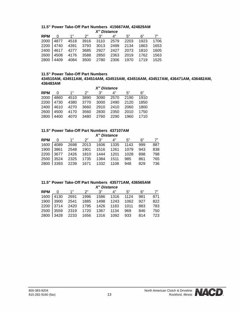
800-383-9204 North American Clutch & Driveline815-282-9160 (fax) 13 Rockford, Illinois
11.5" Power Take-Off Part Numbers 415667AM, 424829AMX" Distance
RPM 0 1" 2" 3" 4" 5" 6" 7”2000 4877 4518 3916 3110 2579 2203 1923 17062200 4740 4391 3793 3013 2499 2134 1863 16532400 4617 4277 3685 2927 2427 2073 1810 16052600 4508 4176 3588 2850 2363 2019 1762 15632800 4409 4084 3500 2780 2306 1970 1719 1525
11.5" Power Take-Off Part Numbers434510AM, 434511AM, 434514AM, 434515AM, 434516AM, 434517AM, 436471AM, 436482AM,436483AM
X" DistanceRPM 0 1" 2" 3" 4" 5" 6"2000 4860 4510 3890 3090 2570 2190 19102200 4730 4380 3770 3000 2490 2120 18502400 4610 4270 3660 2910 2410 2060 18002600 4500 4170 3560 2830 2350 2010 17502800 4400 4070 3480 2760 2290 1960 1710
11.5" Power Take-Off Part Numbers 437107AMX" Distance
RPM 0 1" 2" 3" 4" 5" 6" 7”1600 4089 2698 2013 1606 1335 1143 999 8871900 3861 2548 1901 1516 1261 1079 943 8382200 3677 2426 1810 1444 1201 1028 898 7982500 3524 2325 1735 1384 1511 985 861 7652800 3393 2239 1671 1332 1108 948 829 736
11.5" Power Take-Off Part Numbers 435771AM, 436565AMX" Distance
RPM 0 1" 2" 3" 4" 5" 6" 7”1600 4130 2691 1996 1586 1316 1124 981 8711900 3900 2541 1885 1498 1243 1062 927 8222200 3714 2420 1795 1426 1183 1011 883 7832500 3559 2319 1720 1367 1134 969 846 7502800 3428 2233 1656 1316 1092 933 814 723

North American Clutch & Driveline 800-383-9204Rockford, Illinois 14 (fax) 815-282-9160
2.5 Maximum Safe Operating Speeds
Maximum safe operating speeds of NACD Power Take-Offs with HE or HE(DP) clutches used for either in-lineor side load drives are shown below:
2.6 Required Clutch Torque Capacity
To determine the actual torque capacity required of a clutch used for any given application the maximumengine torque and torque service factor must be considered. See the following chart and formula to calculatethe proper clutch capacity required for the application.
Required Clutch Torque Capacity Calculation:
Required Clutch Torque= Maximum Engine Torque x Service Factor.
Ratings:Shafts, bearings and clutch capacities are rated on a conservative basis. For usually heavy starting loads,frequent engagement service, or if prime mover is engine of less than 4 cylinders, consult NACD's ApplicationEngineering Department for recommendations. Extremely low speed engines require special consideration.
6.5" HE 3700 RPM7.5" HE 3400 RPM8" HE 3250 RPM10" HE 3000 RPM11.5" HE 2800 RPM11.5" HE (DP) 2800 RPM
Torque Service Factors
Blower or Vacuum-Centrifugal with free flow of air . . . . 1.7-With high start-up inertia or
subject to choking of air supply . . . 4.0Compressors
-Reciprocating, 1 or 2 cylinders . . . . 4.0-Reciprocating 3 or more cylinders . . 2.5-Roto screw or turbine . . . . . . . . . . . 2.0
Conveyor-Fed uniformly . . . . . . . . . . . . . . . . . 1.5-Not fed uniformly. . . . . . . . . . . . . . . 2.0-Reciprocating . . . . . . . . . . . . . . . . . 3.0
Drills . . . . . . . . . . . . . . . . . . . . . . . . . . . . 2.0Generator . . . . . . . . . . . . . . . . . . . . . . . . . . 2.0Pump
-Centrifugal or Turbine . . . . . . . . . . . 1.5-Dredge . . . . . . . . . . . . . . . . . . . . . . 2.0-Mud or reciprocating . . . . . . . . . . . . 3.0
Rock Crusher, Hammer Mill. . . . . . . . . . . . . 3.0Snow Blower. . . . . . . . . . . . . . . . . . . . . . . . 2.0Wood Chipper, Saw Mill . . . . . . . . . . . . . . . 3.0

800-383-9204 North American Clutch & Driveline815-282-9160 (fax) 15 Rockford, Illinois
2.7 Alignment Tolerances for Flywheels and Flywheel Housings.
Check the alignment of the engine flywheel and the engine flywheel housing. Excessive bore and face runoutof the flywheel, flywheel housing, and flywheel housing adapters, if used, can adversely affect the performanceof the PTO and the system of which it is a part. A dial indicator will be required to measure alignment.
2.7.a Flywheel housing face runout deviation check
Mount the indicator base on the face of the flywheel and position the dial indicator tip perpendicular to theflywheel housing mounting flange face. Rotate the flywheel through 360 degrees.
The total indicator reading should not exceed:SAE #1, #2, #3 Housing .008 (.203mm)SAE #4, #5, #6 Housing .006 (.152mm)
2.7.b Flywheel housing bore runout deviation check
Mount the indicator base on the face of the flywheel and position the dial indicator tip so its movement isperpendicular to the pilot bore surface of the flywheel housing. Rotate the flywheel through 360 degrees.
The total indicator reading should not exceed:SAE #1, #2, #3 Housing .008" (.203mm)SAE #4, #5, #6 Housing .006" (.152mm)
NOTE: NACD recommends that engine flywheel housings used with NACD PTOs be made of quality castiron or other material of equal or better strength. Aluminum flywheel housings have been found to provideinsufficient strength to properly maintain bearing alignment and support the weight and forces related to the
application.
NOTE: The flywheel and crankshaft of the engine must be heldagainst either the front or rear of the crankshaft thrust bearing while the
total indicator sweep (TIR) measurement is being made.
NOTE: Identify SAE housings. See Basic Dimensions for SAE Housings section 2.1 foridentification of SAE Housings.

North American Clutch & Driveline 800-383-9204Rockford, Illinois 16 (fax) 815-282-9160
2.7.c Flywheel face runout deviation check.
Mount the indicator base on the flywheel housing and position the dial indicator tip so its movement isperpendicular to the face of the flywheel. The indicator tip should be positioned near the drive ring mountingbolt circle diameter. Rotate the flywheel through 360 degrees.
Measure the diameter of the drive ring bore in the flywheel.
Clutch Size (ref) Drive Ring Bore Dia. Maximum T.I.R.6.5" HE 8.5" (21.59cm) .004" (.102mm)7.5" HE 9.5" (24.13cm) .005" (.127mm)7.5" HE 11.125" (28.26cm) .006" (.152mm)8" HE 10.375" (26.35cm) .005" (.127mm)8" HE 11" (27.94cm) .006" (.152mm)10" HE 12.375” (31.43cm) .006" (.152mm)10" HE 13" (33.02cm) .007" (.178mm)11.5" HE 13.875" (35.24cm) .007" (.178mm)11.5" HE 15.5" (39.37cm) .008" (.203mm)
2.7.d Flywheel drive ring pilot bore runout deviation check.
Mount the indicator base on the flywheel housing and position the dial indicator tip so its movement isperpendicular to the drive ring pilot bore surface of the flywheel. Rotate the flywheel through 360 degrees.
NOTE: The flywheel and crankshaft of the engine must beheld against either the front or rear of the crankshaft thrustbearing while the total indicator sweep (TIS) measurement
is being made.
The total indicator reading should not exceed:0.005 inches (0.127 mm)
800-383-9204 North American Clutch & Driveline815-282-9160 (fax) 17 Rockford, Illinois
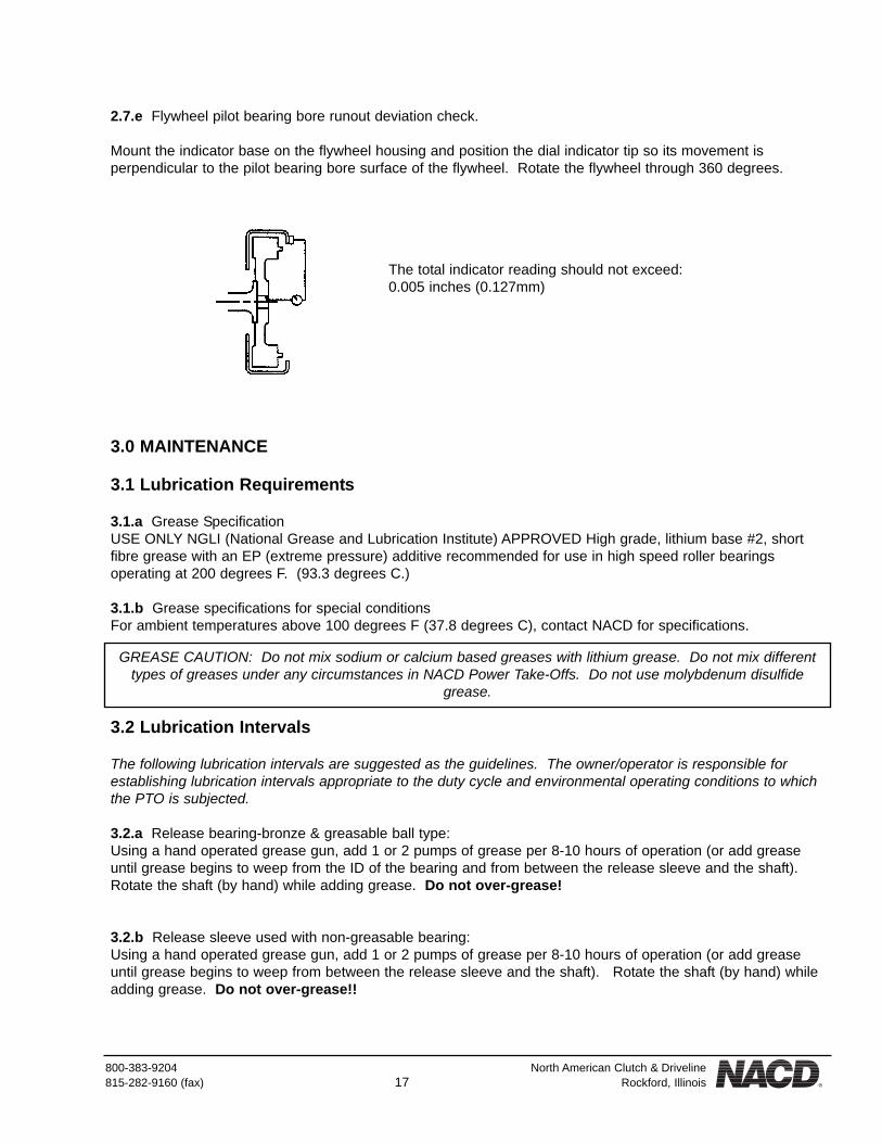
2.7.e Flywheel pilot bearing bore runout deviation check.
Mount the indicator base on the flywheel housing and position the dial indicator tip so its movement isperpendicular to the pilot bearing bore surface of the flywheel. Rotate the flywheel through 360 degrees.
3.0 MAINTENANCE
3.1 Lubrication Requirements
3.1.a Grease SpecificationUSE ONLY NGLI (National Grease and Lubrication Institute) APPROVED High grade, lithium base #2, shortfibre grease with an EP (extreme pressure) additive recommended for use in high speed roller bearingsoperating at 200 degrees F. (93.3 degrees C.)
3.1.b Grease specifications for special conditionsFor ambient temperatures above 100 degrees F (37.8 degrees C), contact NACD for specifications.
3.2 Lubrication Intervals
The following lubrication intervals are suggested as the guidelines. The owner/operator is responsible forestablishing lubrication intervals appropriate to the duty cycle and environmental operating conditions to whichthe PTO is subjected.
3.2.a Release bearing-bronze & greasable ball type:Using a hand operated grease gun, add 1 or 2 pumps of grease per 8-10 hours of operation (or add greaseuntil grease begins to weep from the ID of the bearing and from between the release sleeve and the shaft).Rotate the shaft (by hand) while adding grease. Do not over-grease!
3.2.b Release sleeve used with non-greasable bearing:Using a hand operated grease gun, add 1 or 2 pumps of grease per 8-10 hours of operation (or add greaseuntil grease begins to weep from between the release sleeve and the shaft). Rotate the shaft (by hand) whileadding grease. Do not over-grease!!
The total indicator reading should not exceed:0.005 inches (0.127mm)
GREASE CAUTION: Do not mix sodium or calcium based greases with lithium grease. Do not mix differenttypes of greases under any circumstances in NACD Power Take-Offs. Do not use molybdenum disulfide
grease.

North American Clutch & Driveline 800-383-9204Rockford, Illinois 18 (fax) 815-282-9160
3.2.c Main bearings:Grease every 100 hours of operation. Add grease until grease is forced out of the labyrinth seal(s) around theshaft. Manually (not by starting the engine) rotate the shaft while adding grease.
3.2.d PTO cross shaft:Grease every 500 hours of operation. Add one or two pumps of grease from a hand operated grease gun.
3.2.e Clutch linkage and levers:Lubricate sparingly with engine oil every 500 hours of operation.
3.2.f Pilot bearing: (except non-greasable type)Using a hand operated grease gun, add 1 or 2 shots of grease per 100 hours of operation.
3.2.g Pilot bearing: (non-greasable type)Cartridge-type pilot bearings are sealed units and require no additional lubrication.
The lubrication intervals and the amount of grease used should be adjusted to minimize the amount of greaseforced out of the housing and the clutch release bearing. A small amount of grease driven from the housingand clutch release bearing is an indication that enough grease is being provided.
3.3 Bearing Operating Temperature
3.3.a Main Bearing:Operating temperature range is normally between 170 degrees F, and 200 degrees F (76.7 degrees C to 93.3degrees C). Locations with high ambient temperatures such as desert climates will cause the bearings tooperate at a higher temperature. More frequent lubrication intervals and/or specialized grease designed forhigher operating temperatures will be required. See following note.
NOTE: On some models the grease fitting on the release bearingmust be accessed by opening or removing a small cover located on
the side of the housing.
Pilot bearing(Some PTO shafts have 2 possible grease locations; one locationwill be plugged and the other will have a grease fitting. If the PTOuses a non-greaseable cartridge type pilot bearing, both locationswill be plugged or the shaft will have no drilled passageways at all.)

800-383-9204 North American Clutch & Driveline815-282-9160 (fax) 19 Rockford, Illinois
3.4 Methods of Measuring Clutch Engagement Force
The model 6.5" HE, 7.5" HE, 8" HE, 10" HE, 11.5" HE and 11.5" HE (DP) clutches described in this manual donot automatically adjust to compensate for wear of the clutch facing(s), and therefore must be manually adjust-ed. Maintaining the correct engagement pressure is the responsibility of the owner/operator. The owner/oper-ator must periodically adjust the clutch to ensure correct clutch operation. See section 3.5.
The clutch should be adjusted if the force required to engage the clutch drops by 10-15% of the specifiedengagement force. Destructive damage may have already occurred if engagement force is allowed to diminishto the point where the clutch fails to carry the load (slippage), or if facing(s) have overheated.
3.4.a Torque wrench method (preferred method).
A torque wrench should be used at the cross shaft to measure engagement force. The following chart showstorque readings that represent proper clutch engagement force. The clutch should ENGAGE within the torquereadings shown.
An adapter, NACD part number 236484AM, may be obtained to provide a 1.5" hex nut at the end of the crossshaft. The adapter may be used in place of the standard handle for the purpose of checking clutch adjustmentwith a torque wrench, or it may be installed on the end of the cross shaft opposite the standard handle. (MostPTOs have serrations on both ends of the cross shaft.) All NACD handles are cast with this hex.
Clutch Size Engagement Torque& Type (measured at cross shaft)6.5" HE 50-58 ft-lbs (68-79Nm)7.5" HE 50-58 ft-lbs (68-79Nm)8" HE 65-72 ft-lbs (88-98Nm)10" HE 101-108 ft-lbs (137-146Nm)11.5" HE (3.00" Yoke) 108-115 ft-lbs (146-156Nm)11.5" HE(DP) (3.00" Yoke) 108-115 ft-lbs (146-156Nm)11.5" HE(DP) (3.75" Yoke) 115-127 ft-lbs (156-172Nm)
NOTE: There is a tendency to test temperature with the hand. However, it is difficult to hold a hand on abearing housing operating at 150 degrees F (65.6 degrees C) although that temperature is below the normal170 degree F (76.7 degrees C) operating temperature of the PTO. Therefore a thermometer (contact type)should be used to make reasonably accurate temperature measurements.
CAUTION: Torque wrench readings are in FOOT-POUNDS, which are different values from spring scalereadings which are in POUNDS OF FORCE. There is no direct correlation between FOOT-POUNDS andPOUNDS OF FORCE. Do not confuse the two different kinds of values.
NOTE: New clutches or new facings usually require several, frequent adjustments until the friction facingsurfaces have "worn in". The clutch friction facing plate(s) will become glazed, and possibly permanentlydamaged if the clutch is permitted to slip excessively.
NOTE: If the facings have been slipped excessively, and enough heat was generated that the facings began tosmoke, the clutch material may have been destroyed. Excessive heat normally destroys the friction material.
Therefore further clutch adjustment will not remedy slippage problems. Replace "burned" facing plates.
NOTE: These values include 15%allowance for friction within the clutch
release mechanism.

North American Clutch & Driveline 800-383-9204Rockford, Illinois 20 (fax) 815-282-9160
3.4.b Spring scale method using a standard handle.
Determine whether the engagement force is correct. Measure the distance from thebottom of the handle grip location to the center of the cross shaft. Attach a spring scale tothe handle at the location specified below and pull the scale perpendicular to the handle tomeasure the force required to engage the clutch.
Handle LengthCross Shaft to
Grip12” (30.48cm)
6.5” HESAE #4, #5, #6
12” (30.48cm)7.5” HE
SAE #4, #5, #6
12” (30.48cm)8” HE
SAE #4
16” (40.64 cm)8” HE
SAE #3
12” (30.48cm)10” HESAE #4
ReleaseYoke
Length
3.0” (7.62cm)
3.0” (7.62 cm)
3.0” (7.62 cm)
3.0” (7.62 cm)
3.0” (7.62 cm)
EngagementForce
45 - 65 lbs (200-289N)41 lbs. (182 N)38 lbs. (169 N)
45 - 65 lbs (200-289N)41 lbs. (182 N)38 lbs. (169 N)
60 - 80 lbs (267-356N)54 lbs. (240 N)51 lbs. (227 N)
45 - 60 lbs (200-267N)41 lbs. (182 N)38 lbs. (169 N)
95-120 lbs (423-534 N)85 lbs (378 N)81 lbs (360 N)
Original Setting10% decrease15% decrease
Original Setting10% decrease15% decrease
Original Setting10% decrease15% decrease
Original Setting10% decrease15% decrease
Original Setting10% decrease15% decrease
16” (40.64 cm)8” HE
SAE #2, #3
21” (53.34 cm)10” HESAE #1
16” (40.64 cm)11.5” HE &
HE(DP) SAE #4
21” (53.34 cm)11.5” HE &
HE(DP) SAE #1
16” (40.64 cm)11.5” HE(DP)SAE #2, #3
3.0” (7.62 cm)
3.0” (7.62 cm)
3.0” (7.62 cm)
3.0” (7.62 cm)
3.75” (9.53 cm)
70 - 90 lbs (311-400N)63 lbs. (280 N)59 lbs. (262 N)
55 - 70 lbs (245-311N)50 lbs. (222 N)47 lbs. (209 N)
75 - 95 lbs (334-423N)68 lbs. (302 N)64 lbs. (284 N)
60 - 75 lbs (267-334N)54 lbs. (240 N)51 lbs. (227 N)
95-120 lbs (423-534 N)85 lbs (378 N)81 lbs (360 N)
Original Setting10% decrease15% decrease
Original Setting10% decrease15% decrease
Original Setting10% decrease15% decrease
Original Setting10% decrease15% decrease
Original Setting10% decrease15% decrease
21” (53.34 cm)11.5” HE(DP)
SAE #13.75” (9.53 cm)
75-90 lbs (334-400 N)68 lbs (302 N)64 lbs (284 N)
Original Setting10% decrease15% decrease

800-383-9204 North American Clutch & Driveline815-282-9160 (fax) 21 Rockford, Illinois
3.4.c Spring scale method with altered or special handle length.
Engagement force for standard handle lengths is shown in 3.4.b. For other handle lengths, use the followingformula and refer to the following charts.
X= 1.15 x (A x Y)B
3.5 Clutch Adjustment Procedure
If the clutch requires adjustment, remove the PTO nameplate, disengage the clutch and rotate it to gain accessto the adjusting ring lock.
With a flat blade screwdriver or 7/16" wrench, loosen the adjustment lock bolt (417) and loosen or remove theadjustment lock (419). (See illustration in section 6.2.a)
Rotate the adjusting ring counter-clockwise to tighten the clutch. Rotating the adjustment ring clockwise willloosen the clutch. Adjust to obtain the proper handle engagement force by using one of the methods shown insection 3.4. (Torque wrench method in 3.4.a is the preferred method.)
When clutch is poorly adjusted, reposition the adjustment lock in the notches. Install and tighten theadjustment lock bolt.
Repeat the procedure in 3.4.a, 3.4.b, or 3.4.c, to recheck for proper engagement force.
Clutch Sizeand Type
6.5” HE7.5” HE8” HE
10” HE11.5” HE
11.5” HE(DP)11.5” HE(DP)
Value A
3.0” (7.62cm)3.0” (7.62cm)3.0” (7.62cm)3.0” (7.62cm)3.0” (7.62cm)3.0” (7.62cm)
3.75” (9.53cm)
Value Y
175 - 200# (778 - 887N)175 - 200# (778 - 887N)
225 - 250# (1001 - 1112N)350 - 375# (1557 - 1668N)375 - 400# (1668 - 1779N)375 - 400# (1668 - 1779N)375 - 400# (1668 - 1779N)
X Engagement force atattachment point
Y Engagement force at clutch release bearing
A Length of clutch release yokeB Length of handle (cross shaft to
attachment point)
lbs force
lbs force
inchesinches
(newtons)
(newtons)
(centimeters)(centimeters)
NOTE: A new clutch installation usually requires several adjustments until the friction facing surfaces have“worn in”. The clutch facing(s) will become glazed, and possibly permanently damaged, if the clutch is
permitted to slip excessively.

North American Clutch & Driveline 800-383-9204Rockford, Illinois 22 (fax) 815-282-9160
4.0 INSTALLATION INFORMATION
4.1 Preparation
Do not disengage the clutch before installing the PTO on the engine. Disengagement allows the clutch platesto slip out of the correctly aligned positions established at NACD.
4.1.a If the facing plates have become misaligned, they may be realigned by using the drive ring as a gauge.If the plates require alignment, follow the procedure outlined below.
4.1.b Support the PTO unit with the output shaft hanging straight down. Blocks or a hoist can be used to holdthe PTO in position.
4.1.c Use the clutch drive ring provided with the PTO or remove the drive ring from the engine flywheel touse as an alignment gauge. Place the drive ring over the clutch facings with the clutch disengaged. Mesh thedrive teeth of the facings with the drive ring and align the facings by centering the drive ring relative to the ODof the clutch body. While holding the drive ring and facings centered, engage the clutch.
4.1.d Remove the drive ring.
4.2 Flywheel and Flywheel Housing Alignment Checks
It is strongly recommended that the dial indicator checks be made (as shown in section 2.7) prior to installationof the PTO, especially on new engines or when bearing failures or shaft wear were found after the previousPTO was removed and examined for cause of failure.
4.3 Lubrication Required Before Installation
4.3.a See section 3.1 for information on the type(s) of lubricant(s) required.
4.3.b Lubricate as follows before installation.
(See illustration in section 3.2 for locations of grease fittings.)
Release bearing: (except non-greasable type)Bronze and greasable ball-type release bearing:With a hand operated grease gun, add 1 or 2 pumps of grease per 8-10 hours of operation (or until greasebegins to weep from the I.D. of the bearing and the release sleeve. Rotate the shaft (by hand) while addinggrease. Do not over-grease!!
Release bearing: (non-greasable type)Non-greasable ball bearing type release bearing:Sealed bearing- no lubrication required.

800-383-9204 North American Clutch & Driveline815-282-9160 (fax) 23 Rockford, Illinois
Release sleeve used with non-greasable bearing:Using a hand operated grease gun, add 1 or 2 pumps of grease per 8-10 hours of operation (or add greaseuntil grease begins to weep from between the release sleeve and the shaft). Rotate the shaft (by hand) whileadding grease. Do not over-grease!!
Main bearing:With a hand operated grease gun, add 1 or 2 pumps of grease while rotating the shaft (by hand), or untilgrease weeps from the labyrinth seals around the shaft at either end of the bearing housing.
Pilot bearing lube passage:Some PTOs have a hole drilled through the length of the shaft to provide lube to the pilot bearing. The greasefitting may be located either at the end or to the side of the output shaft. Add grease until the center passageis filled with grease. Be sure that the shipping plug is removed from the pilot bearing end of the shaft prior toinstallation.
Cross shaft:With a hand operated grease gun add 1 or 2 pumps of grease into each of the grease fittings located in thePTO housing, near each end of the cross shaft.
4.4 Install the PTO on the Engine
4.4.a Install the drive ring on the engine flywheel. Be sure that the ring is seated in the locating bore. UseUSA SAE Grade 5 bolts (or equivalent) with lockwashers. Torque the bolts according to the chart below.
Use the engine manufacturer's torque specifications if different from the above.
Some engines use metric bolts. Refer to engine manufacturer's torque specifications.
4.4.b (For greasable pilot bearing ONLY). If a pilot bearing adapter is used on the flywheel, be sure themating surfaces between the adapter and the flywheel face are sealed, to prevent loss of grease from the pilotbearing grease cavity due to vacuum or centrifugal force. Loctite 515 or equivalent is suggested.
4.4.c Proceed as follows:
For greasable pilot bearing ONLY: (bearing has a grease shield on 1 side only)
Pack the flywheel pilot bearing cavity with grease. Install the pilot bearing in the flywheel or adapter with thegrease shield of a greasable bearing towards the PTO and clutch. Be sure that the pilot bearing spacer, ifused, is in place. Two types of spacers may be used. Spacers may be installed in the flywheel to keep thepilot bearing from going too far into the bore in the flywheel, and a spacer may be used on the pilot end of thePTO shaft between the pilot bearing and the PTO to help maintain proper pilot bearing location in the flywheelbore.
For non-greasable pilot bearing ONLY: (bearing has 2 grease seals.)
Clutch Sizeand Type
6.5” HE7.5” HE8” HE
10” HE11.5” HE
11.5” HE(DP)
Bolt Size
5/16 - 185/16 - 183/8 - 163/8 - 163/8 - 163/8 - 16
TorqueSpecification
15-18 ft-lbs (20 - 24 Nm)15-18 ft-lbs (20 - 24 Nm)
26 - 35 ft-lbs (35 - 43 Nm)26 - 35 ft-lbs (35 - 43 Nm)26 - 35 ft-lbs (35 - 43 Nm)26 - 35 ft-lbs (35 - 43 Nm)

North American Clutch & Driveline 800-383-9204Rockford, Illinois 24 (fax) 815-282-9160
Non-greasable, double-sealed pilot bearings require no re-lubrication and may be installed in the flywheel oradapter with either side toward the PTO and clutch. The shaft should have no grease fittings. If it does,remove the grease fitting(s) and replace with pipe plugs as a precaution to insure grease is not forced into thepilot bearing cavity of the flywheel. A build-up of pressure caused by forcing grease into the cavity can causethe pilot bearing to be forced out of the flywheel, resulting in a bearing or shaft failure.
4.4.d Install the PTO with the cross shaft in a horizontal position. Install two 5" long guide bolts in theflywheel housing holes, located approximately at the 3 o'clock and 9 o'clock positions. Position the PTO onthe guide bolts to help align the unit and support the weight while the mounting bolts are installed.
Start the PTO shaft in the pilot bearing. Carefully align the clutch facing teeth with the teeth in the drive ring.Temporarily install longer bolts in 4 bolt holes 90 degrees apart, and tighten the bolts alternately and evenly todraw the PTO housing toward the flywheel housing. Replace the longer bolts with shorter ones as necessary,and tighten to draw the PTO into place. Then remove the temporary bolts and guide bolts, and replace themwith proper mounting bolts. Install bolts and lockwashers. Use USA SAE Grade 5 bolts (or equivalent) withlockwashers. Torque bolts according to the following chart.
Use the engine manufacturer's torque specifications if different from the above torque recommendation.
4.4.e Rap the output end of the shaft with a soft mallet to relieve any pre-load on the engine crankshaft thatmay have built up as a result of the pilot bearing's fit on the shaft pilot.
4.5 Correct Handle Installation Position
Install the clutch handle or release mechanism. Position the handle so that it is pointingeither straight up or straight down when the clutch is in the engaged position. Positioningthe lever vertically minimizes loading on the release bearing.
If an altered or special clutch engagement mechanism is used (remote linkage mechanism isnot recommended), be sure there is not pre-load on the release bearing either sideways ortoward the engaged or released position. There should be no pre-load on the cross shaft inany direction, forward, rearward or sideways. A torsional and forward or rearward load (only)will be applied (only) during the engagement or disengagement cycle.
4.6 Check Clutch Engagement Pressure
The clutch was properly adjusted at the factory. However, due to variables created by first-time engagements,the clutch engagement pressure should be rechecked to insure proper clutch engagement pressure at the timeof installation. See sections 3.4 and 3.5
NOTE: Many engines use metric threads, so the below chart would not be applicable. Do not use bolts madewith U.S. threads in holes with metric threads. The threads will be damaged, rendering them unusable.
SAE HousingSize#1#2#3#4#5#6
Bolt Size
7/16 - 143/8 - 163/8 - 163/8 - 163/8 - 163/8 - 16
TorqueSpecification
42-50 ft-lbs (57 - 68 Nm)26-35 ft-lbs (32 - 43 Nm)26-35 ft-lbs (32 - 43 Nm)26-35 ft-lbs (32 - 43 Nm)26-35 ft-lbs (32 - 43 Nm)26-35 ft-lbs (32 - 43 Nm)

800-383-9204 North American Clutch & Driveline815-282-9160 (fax) 25 Rockford, Illinois
4.6.a Adjust the clutch if necessary.
4.7 Attaching and Shimming an Outboard Shaft Support Bearing(OPTIONAL SUPPORT - SPECIAL APPLICATIONS ONLY)
4.7.a The power take off must be bolted to the engine.
4.7.b Bolt and torque the outboard bearing support member to the frame.
4.7.c Install the outboard bearing on the PTO shaft in the position where it will later be tightened to the out-board bearing support member, but leave a small gap in the shim slot at this time.
NOTE: New clutches or new facings usually require several, frequent adjustments until the friction facingsurfaces have “worn in”. The clutch friction facing will become glazed, and possibly permanently damaged if
the clutch is permitted to slip excessively.
NOTE: Perform the following procedure carefully and precisely. Misaligned bearings result in PTO failures.
The following shimming procedures for shimming the outboard bearing must be carefully followed. It is imper-ative that the three (3) support bearings (pilot bearing, PTO main bearings(s) and outboard bearing) be inclose alignment. The outboard bearing will help support the side loads imposed on the PTO shaft by the
belts. If the three bearings are not installed so that the center of the PTO shaft is in a straight line, reducedbearing life will occur. It is therefore important that the internal PTO bearings be properly installed and adjust-
ed, and that the outboard bearing NOT impose a load which would tend to bow the center line of the PTOshaft.
NOTE: NACD does not supply outboard bearings.

North American Clutch & Driveline 800-383-9204Rockford, Illinois 26 (fax) 815-282-9160
4.7.d Secure (2) dial indicators to a solid base. Place the points of the indicators on top and side of the shaft,as close as possible to the outboard bearing. Set the dial indicators to "0".
4.7.e Properly torque the bolts securing the outboard bearing to the support member.
4.7.f Read the dial indicator. Add shims until the indicator reads 0+ 0.001 inches (0.0254mm) after installingand properly torquing the mounting bolts.
4.7.g Tighten the belts using accurate tensioning methods and an accurate belt tensioning gage. The beltsshould not be tightened until all the mounting bolts have been tightened. Make sure that the side loads arelower than those listed in the allowable side load tables in section 2.4.
5.0 OPERATION
5.1 Clutch Engagement Procedure
5.1.a The PTO clutch should normally be engaged with the engine operating below 1,000 RPM. After the loadhas been brought up to engine speed, and the clutch is no longer slipping, the engine speed may be increasedto operating speed.
5.1.b Where high inertia loads must be picked up, engaging the clutch at 1,000 RPM may result in stalling theengine. Heavy inertia loads may be brought up to speed by a series of short engagements anddisengagements at intervals long enough to prevent excessive heat build up in the facings. Under extremecircumstances, the engine may have to be operated at higher speeds while engagement occurs, but UNDERNO CIRCUMSTANCES should the clutch be slipped for more than a second or two without either fullyengaging the clutch or completely disengaging the clutch to permit it to cool.

800-383-9204 North American Clutch & Driveline815-282-9160 (fax) 27 Rockford, Illinois
6.0 EXPLODED VIEWS - TYPICAL POWER TAKE-OFFS6.1 Typical configuration for SAE housing size 4, 5 or 6 with 6.5” or 7.5” clutch illustrated

North American Clutch & Driveline 800-383-9204Rockford, Illinois 28 (fax) 815-282-9160
6.1.a Clutch assembly exploded view

800-383-9204 North American Clutch & Driveline815-282-9160 (fax) 29 Rockford, Illinois
6.2 Typical configuration for SAE housing size 4 with 10” clutch illustrated

North American Clutch & Driveline 800-383-9204Rockford, Illinois 30 (fax) 815-282-9160
6.2.a Clutch assembly exploded view

800-383-9204 North American Clutch & Driveline815-282-9160 (fax) 31 Rockford, Illinois
6.3 Typical configuration for SAE housing size 1,2,3 or 4 with 8”, 10” or 11.5” clutch shown

North American Clutch & Driveline 800-383-9204Rockford, Illinois 32 (fax) 815-282-9160
6.3.a Clutch assembly exploded view

800-383-9204 North American Clutch & Driveline815-282-9160 (fax) 33 Rockford, Illinois
6.4 Typical configuration for SAE housing size 1,2 or 3 with 11.5” DP clutch shown

North American Clutch & Driveline 800-383-9204Rockford, Illinois 34 (fax) 815-282-9160
6.4.a Clutch assembly exploded view

800-383-9204 North American Clutch & Driveline815-282-9160 (fax) 35 Rockford, Illinois
1 Bell Housing
2 Name Plate
4 Bolt
5 Grease Zerk
6 Jam Nut
7 Grease Zerk
8 Drive Shaft
9 Main Bearings
10 Bearing Retainer
11 Adjusting Lock
12 Lock Bolt
13 Lock Washer
14 Cross Shaft
15 Woodruff Key
17 Release Yoke
18 Bolt
19 Washer
20 Shifting Lever Sub-Assembly
21 Shifting Lever
22 Bolt
23 Washer
24 Output Key
25 Pilot Bearing
26 Nut
27 Locking Washer
28 Clutch Key
29 External Snap Ring
32 Grease Tube
33 Grease Fitting (Cross Shaft)
68 Internal Snap Ring
69 Grease Fitting (End of Shaft)
78 Headless Setscrew
79 Clutch Assembly
81 Pipe Plug
109 Clutch Body
110 Facing Plate
111 Center Plate
112 Pressure Plate
113 Adjusting Ring
125 Release Sleeve
127 Release bearing kit
132 Sleeve & Bearing Assembly
134 Name Plate
135 Drive Screw
136 Pressure Plate Assembly
146 Wear Plate
412 Lever Spring
413 Lever
414 Clevis Pin
415 Retainer Ring
417 Lock Bolt
418 Lock Washer
419 Adjustment Lock
430 Link
431 Clevis Pin
432 Retaining Ring
433 Clevis Pin
434 Retainer Ring
436 Seperator Spring
437 Roll Pin
935 Drive Ring
6.5 Universal Bill of Materials

North American Clutch & Driveline 800-383-9204Rockford, Illinois 36 (fax) 815-282-9160
7.0 DISASSEMBLE THE POWER TAKE-OFF
(Refer to parts illustrations in section 6.0)
7.1 Remove All Accessories or Drives Attached To the Output Shaft
7.1.a Engage the clutch.
7.1.b Disconnect any linkage which may be attached to the clutch actuating handle.
7.1.c If the handle must be removed to permit removal of the Power Take-Off from the engine, loosen the bolt(22) which fastens the handle to the cross-shaft.
7.1.d Match-mark the handle and cross shaft so that the handle can be reinstalled at the same place on theshaft.
7.1.e Slide the handle off of the cross shaft spline.
7.2 Remove the Power Take-Off From the Engine
7.2.a Attach a hoist or other suitable lifting device to the power take-off. Attach at 3 points spanning thecenter of gravity to hold the shaft in a horizontal position during removal.
7.2.b Remove the mounting bolts, removing those located near the top last. The PTO should separate fromthe flywheel housing. If the PTO doesn't separate, install two bolts in the threaded holes in the flange.
Holes are tapped for:
#1 Housing: 7/16” - 14 bolts#2, #3, #4 Housing: 3/8” - 16 bolts#5, #6 Housing: 3/8” - 16 bolts
Tighten the bolts evenly until the housing is removed from the engine flywheel housing pilot diameter.
7.2.c Exercise caution when removing the PTO from the engine to avoid damage to the grease fittings,facing(s), and pilot bearing.
7.3 Remove the Clutch From the PTO Shaft
7.3.a Remove the pilot bearing (25) from the shaft using a split-plate bearing puller.
7.3.b If not done in 7.1.b thru 7.1.e, loosen bolt (22) and remove the handle (21).
7.3.c Remove jam nut (6) securing the grease hose (if the release bearing is a regreasable type and a greasehose is used) and disconnect the hose fitting from the bell housing. The grease hose may now be removedfrom the release bearing (127) (or it may be removed after the clutch is removed from the shaft).
7.3.d Position the PTO with the pilot bearing end up, resting with support beneath the end of the output shaft(the impact force of the mallet blow in step 7.3.f will therefore be absorbed through the shaft rather than acrossthe main bearing(s).

800-383-9204 North American Clutch & Driveline815-282-9160 (fax) 37 Rockford, Illinois
7.3.e Bend the locking washer (27) away from nut (26), and remove the nut and locking washer.7.3.f Place pry bars under the pressure plate. While exerting pressure on the pry bars, strike the end of theshaft with a soft mallet to "jar" the clutch loose. Pull the clutch from the shaft.
The following illustrate standard bearing and bearing housing configurations found in NACD Power Take-Offs."Specials" have been designed and sold, but they are only slight variations of these standard configurations.
CAUTION: Do not damage the pilot end of the shaft.

North American Clutch & Driveline 800-383-9204Rockford, Illinois 38 (fax) 815-282-9160
7.4 Remove the Shaft and Bearings From the Housing
CONFIGURATIONS A, B and D only:7.4.a Remove lock bolt (12) , lockwasher (13) and adjustment lock (11).
7.4.b Rotate the bearing retainer (10) counter-clockwise and remove it.
7.4.c Lift the drive shaft (8) with bearing(s) (9) from the bearing housing (a hoist may be needed).
7.4.d Configuration A only: One tapered roller bearing cup will have remained in the bearing housing.Remove the bearing cup from the bearing housing.
Insert a small punch through the three holes provided in the rear of the bearing housing and drive the cup out.(Some units have threaded plugs which first must be removed from the holes).
CONFIGURATION C only:7.4.e Remove internal snapring (68).
7.4.f Lift the drive shaft (8) with bearing (9) from the bearing housing (a hoist may be needed).
7.5 Remove the Main Bearings From the Drive Shaft
Wash the bearings and bearing cups with clean fuel oil or solvent. Dry and carefully examine for wear,corrosion or rough spots. If it is determined the bearing(s) must be replaced, remove from the shaft.
Configuration A only:7.5.a Place the shaft in a press with a split-plate resting on the bed of the press, positioned under the topbearing inner race.
Configuration C: Proceed to 7.4.e
Proceed to 7.5
Configuration B, C and D: Proceed to 7.5.d

800-383-9204 North American Clutch & Driveline815-282-9160 (fax) 39 Rockford, Illinois
7.5.b Press the shaft from the bearing.
7.5.c Turn the shaft over and repeat steps 7.5.a and 7.5.b to remove the remaining bearing (9).
CONFIGURATION B, C and D only:7.5.d Remove 1 or 2 external snapring(s) (29).
7.5.e Support beneath bearing (9) on the bed of a press.
7.5.f Press the drive shaft from the bearing.
7.6 Remove the Cross Shaft
7.6.a Loosen two bolts (18) securing the yoke assembly (17) to the cross shaft.
7.6.b Slide the cross shaft through the housing until the yoke rests against a block of wood placed betweenthe yoke and the housing.
7.6.c With a soft mallet, drive the cross shaft out of the yoke just far enough to expose two woodruff keys (15).7.6.d Remove the woodruff keys.
7.6.e Slide or tap the cross shaft out of the yoke and housing.
8.0 INSPECT THE POWER TAKE-OFF COMPONENTS
8.1 Ball bearings:
8.1.a Visually examine for indications of wear, corrosion, or pitting on balls and races. Apply clean, lightweightengine oil and slowly rotate the outer race while holding the inner race. The balls must roll free. Rough orsticking spots must be checked to be sure they are not particles of dirt. If they are, clean and check again. Ifnot dirt, replace the bearing.
8.2 Tapered Roller Bearings:8.2.a Visually examine for indications of wear, corrosion, brinelling or pitting on races or rollers. Rollers mustnot have flat spots or pitting. Bearing cups and cones must not exhibit signs of pitting, scuffing or tracking.
CAUTION: Place a block of wood beneaththe shaft to prevent it from being damaged
as it falls loose.
CAUTION: If the inner race of the pilot bearing is still on theshaft (roller bearing style) place a plug on the end of the
shaft to prevent pressing against the pilot bearing inner race.
Proceed to 7.6
CAUTION: Place a block of wood beneath the shaft to prevent it from being damaged as it falls loose.
NOTE: The yoke may be loose enough to slide out without use of a mallet.

North American Clutch & Driveline 800-383-9204Rockford, Illinois 40 (fax) 815-282-9160
Lightly oil the races with clean oil, hold one race stationary while slowly rotating the other race against it.Rough spots or sticking indicate need for replacement. Races must be smooth and unworn.
8.3 Bell Housing:
8.3.a Check the bearing fit. Bearing races usually are designed with a sliding or slightly snug fit in thehousing bore. They should not have side movement in the bore. Labyrinth seal bores at the output end of thebearing housing should be round, not worn oval and should be approximately .020:-0.25" (.508mm-.635mm)diameter larger than the drive shaft.
8.3.b Threads for the bearing retainer should not be damaged.
8.3.c If a bearing failure has occurred, be sure the bearing has not spun in the housing, destroying theshoulder or bore contacted by the bearing. Although the moveable bearing retainer will compensate for smallamounts of shoulder wear, it is imperative the bearing contact the housing only at the OD of the race, and notanywhere else on the bearing in its assembled and adjusted position.
8.3.d The mounting pilot OD and mounting face must be free of protruding metal, rust, corrosion etc., whichwould prevent the housing from locating properly in the flywheel housing bore or against the flywheel housingface. An improper fit causes misalignment. Misalignment is a major cause of Power Take-Off failure. InConfiguration C the snapring should restrict bearing movement to .015" (.381mm) maximum.
8.3.e Cross shaft holes should not be worn more than .015" (.381mm) out of round. A little wear does not ren-der the parts unserviceable, but excessive wear can cause binding of the cross shaft under load during clutchengagement.
8.4 Bearing Retainer:
8.4.a Threads must not be damaged. A surface that presses against the bearing or bearing shims must besmooth, with no metal protrusions above the surface. A small indentation below the surface is not detrimental.
8.5 Cross Shaft:
8.5.a Be sure the cross shaft moves freely in the bell housing. Remove rust or corrosion from the cross shaftand the holes in the bell housing. Wear on the cross shaft does not become detrimental until it inhibits smoothrotation during clutch engagement (creates a false clutch engagement pressure reading) or allows moisture,dirt, or other corrosives to enter the housing. This can be prevented by ample greasing through the greasefittings to keep the cross shaft lubed.
8.5.b Woodruff key slots must hold the keys straight. If the release yoke has been loose on the cross shaft,the keyways may have one side worn at an angle.
8.6 Clutch Release Yoke:
8.6.a Keyways must not be worn excessively.
8.6.b Replace if width of cradles is over:
6.5", 7.5" and 8" (Bronze Brg.) .645" (16.38mm)8" (Ball Brg.), 10" and 11.5" .765" (19.43mm)
800-383-9204 North American Clutch & Driveline815-282-9160 (fax) 41 Rockford, Illinois
8.7 Drive Shaft:
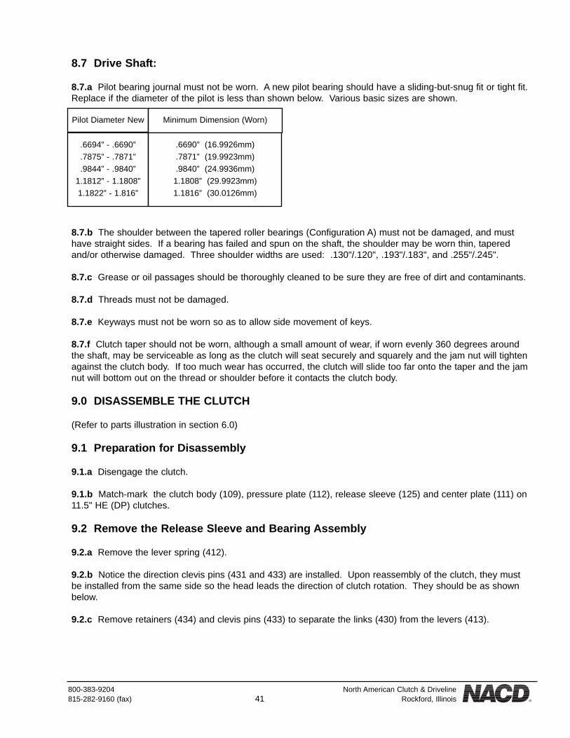
8.7.a Pilot bearing journal must not be worn. A new pilot bearing should have a sliding-but-snug fit or tight fit.Replace if the diameter of the pilot is less than shown below. Various basic sizes are shown.
8.7.b The shoulder between the tapered roller bearings (Configuration A) must not be damaged, and musthave straight sides. If a bearing has failed and spun on the shaft, the shoulder may be worn thin, taperedand/or otherwise damaged. Three shoulder widths are used: .130"/.120", .193"/.183", and .255"/.245".
8.7.c Grease or oil passages should be thoroughly cleaned to be sure they are free of dirt and contaminants.
8.7.d Threads must not be damaged.
8.7.e Keyways must not be worn so as to allow side movement of keys.
8.7.f Clutch taper should not be worn, although a small amount of wear, if worn evenly 360 degrees aroundthe shaft, may be serviceable as long as the clutch will seat securely and squarely and the jam nut will tightenagainst the clutch body. If too much wear has occurred, the clutch will slide too far onto the taper and the jamnut will bottom out on the thread or shoulder before it contacts the clutch body.
9.0 DISASSEMBLE THE CLUTCH
(Refer to parts illustration in section 6.0)
9.1 Preparation for Disassembly
9.1.a Disengage the clutch.
9.1.b Match-mark the clutch body (109), pressure plate (112), release sleeve (125) and center plate (111) on11.5" HE (DP) clutches.
9.2 Remove the Release Sleeve and Bearing Assembly
9.2.a Remove the lever spring (412).
9.2.b Notice the direction clevis pins (431 and 433) are installed. Upon reassembly of the clutch, they mustbe installed from the same side so the head leads the direction of clutch rotation. They should be as shownbelow.
9.2.c Remove retainers (434) and clevis pins (433) to separate the links (430) from the levers (413).
Pilot Diameter New
.6694” - .6690”
.7875” - .7871”
.9844” - .9840”1.1812” - 1.1808”1.1822” - 1.816”
Minimum Dimension (Worn)
.6690” (16.9926mm)
.7871” (19.9923mm)
.9840” (24.9936mm)1.1808” (29.9923mm)1.1816” (30.0126mm)

North American Clutch & Driveline 800-383-9204Rockford, Illinois 42 (fax) 815-282-9160
9.3 Disassemble the Sleeve and Bearing Assembly
9.3.a (Ball type release bearing): Remove the grease hose (32) (if the bearing is a regreasable style and agrease hose is used).
9.3.b Remove 3 retainers (432) and clevis pins (431) to remove the links (430) from the release sleeve (125).
9.3.c Remove the external snapring (129) from the release sleeve.
9.3.d Using a split plate as close to the release sleeve as possible, support beneath the release bearing andbearing carrier (126) on the bed of a press. Press the release sleeve from the bearing.
9.3.e Remove the internal snapring (128).
9.3.f Tap the bearing carrier (126) off the release bearing.
9.3.g (Bronze-type release bearing):Match-mark the two halves of the bronze release bearing (127). Observe whether a machined side is up ordown so it may be reinstalled in the same direction.
9.3.h Remove the grease hose (32) (if the bearing is a regreasable style and a grease hose is used).
9.3.i Remove 3 retainers (432) and clevis pins (431) to remove links (430) from the release sleeve (125).
9.3.j Loosen and remove 2 bolts and nuts holding the release bearing together. Remove the release bearingfrom the sleeve.
Proceed to 9.4

800-383-9204 North American Clutch & Driveline815-282-9160 (fax) 43 Rockford, Illinois
9.4 Remove the Levers
Note the direction the clevis pins (414) are installed so they can be reinstalled in the same direction. Remove(3) retainers (415) from the clevis pins (414). Press down on the pressure plate to compress the separatorsprings (436) and allow removal of the clevis pins. Remove the clevis pins (414) to separate the levers fromthe clutch body.
9.5 Remove and Disassemble the Pressure Plate Assembly
9.5.a Lift the pressure plate assembly from the clutch body.
9.5.b Remove the wear ring (146) from inside the adjusting ring.
9.5.c Remove the adjustment lock bolt (417), lockwasher (418) and adjustment lock (419) from the pressureplate.
9.5.d Rotate the adjusting ring counter-clockwise to remove it from the pressure plate.
9.6 Complete the Disassembly of the Clutch
9.6.a Remove the facing plate (110).
9.6.b Remove 3 separator springs (436) from the pockets in the clutch body.
(11.5" HE(DP)(2 plate) clutches only):9.6.c Remove the center plate (111) and the remaining facing plate.
9.6.d If the spring pins (437) are worn or damaged, remove them from the clutch body.
10.0 INSPECT THE CLUTCH COMPONENTS
10.1 Clutch Body:
10.1.a Friction surface must not have heat cracks, must be smooth and must be flat within .005" (.127mm).
10.1.b Drive bosses must not have wear marks exceeding .003" (.076mm) depth due to wear from thepressure plate or center plate.

North American Clutch & Driveline 800-383-9204Rockford, Illinois 44 (fax) 815-282-9160
10.1.c Keyway must not be worn.
10.1.d Tapered bore must fit snugly and securely on shaft.
10.2 Pressure Plate:
10.2.a Friction surface must not have heat cracks, must be smooth and must be flat within .005" (.127mm).
10.2.b Drive slots must not be excessively worn. Measure the width of the clutch body drive lug in the worncontact area. Measure the width of the pressure plate drive slot in the (worn) contact area. If the differencebetween the two readings exceeds .012" (.305mm) the worn component(s) must be replaced.
10.2.c Threads for adjusting ring must not be damaged.
10.3 Release Sleeve:
10.3.a No fractures should exist in the bosses.
10.3.b Clevis pin holes must not be excessively worn. A small amount of wear is normal and will not bedetrimental.
10.3.c The release sleeve bore should not be worn beyond the limits shown below.
(for use with ball-type release bearing):10.3.d Snapring groove must not be damaged or worn beyond:
10.3.e Ball bearing must fit tight on the release sleeve.
(for use with bronze-type release bearing):10.3.f Shoulder width should not be worn below:
Basic Size
.875” (22.23mm)1.250” (31.75mm)1.375” (34.93mm)1.750” (44.45mm)2.000” (50.80mm)2.250” (57.15mm)2.500” (63.50mm)
Maximum Allowable Diameter
.883” (22.482mm)1.258” (31.953mm)1.387” (35.230mm)1.759” (44.679mm)2.012” (51.105mm)2.259” (57.379mm)2.509” (63.729mm)
Clutch Size Maximum Allowable Width
6.5”, 7.5”8”
10”, 11.5”
.130” (3.30mm)
.145” (3.68mm)
.155” (3.94mm)
Basic Size Minimum Width
5/16” (7.94mm)1/2” (12.70mm)
.304” (7.72mm).493” (12.52mm)

800-383-9204 North American Clutch & Driveline815-282-9160 (fax) 45 Rockford, Illinois
10.4 Release Bearing:
10.4.a (ball type):Clean and lightly oil the bearing. Hold the inner race and slowly rotate the outer race, feeling and listening forrough spots, catches or a sticking condition.
10.4.b (bronze type):Flat areas are usually worn on the trunnions. Measure the trunnion diameter. Replace if worn to less than:
10.4.c Internal slot that straddles the release sleeve shoulder maximum width:
10.5 Bearing Carrier: (ball-type release bearing only)
10.5.a Flat areas are usually worn on the trunnions. Measure the trunnion diameter. Replace if worn to lessthan:
10.5.b The snapring groove must securely hold the snapring. Measure the dimension from the bearingshoulder inside the carrier to the farthest edge of the snapring groove.
10.5.c The bearing fit may be a sliding fit, but must be snug. A slightly tight fit is desirable.
10.6 Facing Plates:
10.6.a Must be free of oil or grease. Must not be burned. Once burned, they normally are incapable ofholding torque.
Clutch Size Minimum Trunnion Diameter
6.5”, 7.5”, 8”8”, 10”, 11.5”
.605” (15.37mm)
.730” (18.54mm)
Basic Size Maximum Width
5/16” (7.94mm)1/2” (12.70mm)
.319” (8.10mm).507” (12.88mm)
Clutch Size Minimum Trunnion Diameter
6.5”, 7.5”8”, 10”, 11.5”
.605” (15.37mm)
.730” (18.54mm)
Clutch Size Maximum Width
6.5”, 7.5”, 8”10”, 11.5”
.700” (17.78mm).814” (20.68mm) or
.891” (22.63mm)

North American Clutch & Driveline 800-383-9204Rockford, Illinois 46 (fax) 815-282-9160
10.6.b Measure the amount of wear which has occurred on each friction surface (2 surfaces per facing disc).Total wear allowable in any clutch (add 2 or 4 surfaces together) is approximately .25" (6.35cm). Thickness ofa new facing plate is:
10.6.c Teeth must not be worn excessively or broken.
10.7 Center Plate:
10.7.a Friction surfaces must not have heat cracks, must be smooth, and must be flat within .005" (.127mm).
10.7.b Drive slots must not be excessively worn. Measure the width of the clutch body drive lug in the slotcontact area and the width of the pressure plate drive slot in the (worn) contact area. If the difference betweenthe two readings exceeds .007" (.180mm) the worn component(s) must be replaced.
10.7.c Minimum thickness of the facing contact area must not be less than .365" (9.27mm).
10.8 Grease Hose:
10.8.a Should be pliable, flexible and free of cracks, holes or wear.
10.8.b Braided wire design: Wire should not be crushed (flattened).
10.9 Levers:
10.9.a Clevis pin holes must not be excessively worn. A small amount of wear is normal and will not bedetrimental.
11.0 ASSEMBLE THE CLUTCH
(Refer to parts illustration in section 6.2)
11.1 Assemble the Sleeve and Bearing Assembly
(Ball-type release bearing):11.1.A Install the release bearing (127) in the bearing carrier (126). The fit should be a snug sliding fit or alight press fit.
6.5”, 7.5”, 8” clutches10” and 11.5” clutches
.375” (9.53mm).437” (11.10mm)

800-383-9204 North American Clutch & Driveline815-282-9160 (fax) 47 Rockford, Illinois
11.1.b Install the internal snapring (128).
11.1.c Press the release bearing onto the release sleeve with the snapring (128) located on the side nearestthe three bosses of the release sleeve. Be sure to press against the inner race of the bearing; do not support,press or tap against the outer race (bearing carrier). Damage to the bearing could result.
11.1.d Install external snapring (129).
(Bronze release bearing):11.1.e Lubricate the inside slot of the bearing halves (127). Place the two halves of the release bearing inposition on the release sleeve (125) (with the machined side up or down as was noted in 9.3.g).
11.1.f Install and tighten the bolts and nuts holding the halves together. Rotate the bearing on the sleeve tobe sure it turns freely.
11.1.g Place two connecting links (430) on one of the bosses of the release sleeve (one on either side of theboss). The travel stop protruding from one side of each link should point toward the bottom of the releasesleeve and must rest against the release sleeve.
11.1.h Install the clevis pin (431) through both links and the boss on the sleeve.
11.1.i Securely install the retainer (432) in the groove of the clevis pin.
11.1.j Repeat 11.1.g thru 11.1.i to install links on the remaining 2 bosses.
Proceed to 11.1.g
NOTE: The clevis pin must be installed as shown below so the head will lead the direction of clutch rotation.

North American Clutch & Driveline 800-383-9204Rockford, Illinois 48 (fax) 815-282-9160
11.2 Assemble the Clutch Body Assembly
11.2.a Place the clutch body (109) on the bench with the friction surface up.
11.2.b Install 3 separator springs (436) in the spring pockets of the clutch body.
11.2.c Place one facing plate (110) on the clutch body.
(11.5" HE(DP) Clutches):11.2.d (If they were removed) install the three spring pins (437) in the clutch body holes to support the separa-tor springs. Drive them to the bottom of the holes.
11.2.e Install 3 separator springs (436) over the spring pins in the clutch body.
11.2.f Place on (whole ring style) facing plate (110) on the clutch body.
11.2.g Place the center plate (111) on top of the facing with the machined "ramps" located along the sides ofthe drive slots facing down (away from the pressure plate). Then place a second (whole ring style) facing plateon top of the center plate.
11.2.h Thread the adjusting ring (113) into the pressure plate (112) almost to the bottom of the thread.
11.2.i Place the wear ring (146) in the adjusting ring.
11.2.j Place the pressure plate assembly on top of the facing plate, aligning the drive slots on the drive bossesof the clutch body.
11.3 Install the Release Levers
11.3.a Position the 3 levers (413) in the lever bosses with the protruding tang against the wear ring up and the
Proceed to 11.2.h
CAUTION: NACD DOES NOT APPROVE the use of seg-mented facings in 2-plate (DP) clutches.
11.5” HE(DP) Clutches: Proceed at 11.2.d

800-383-9204 North American Clutch & Driveline815-282-9160 (fax) 49 Rockford, Illinois
"long end" up. (See illustration in section 11.1.)
11.3.b Press down on the pressure plate to compress the separator springs and allow the clevis pins (414) tobe inserted through the lever and clutch body.
11.3.c Securely install retainers (415) on the clevis pins.
11.4 Install the Release Sleeve and Bearing Assembly on the Clutch
11.4.a Position the sleeve and bearing assembly on the clutch so the links align with the levers.
11.4.b Align the clevis pin holes and install a clevis pin (433) through the links and levers so the head of theclevis pin will lead the direction of rotation during clutch operation.
11.4.c Securely install the retainer (434) in the groove of the clevis pin.
11.4.d Repeat 11.4.b and 11.4.c at the remaining lever positions.
11.4.e Install the lever spring (412) over the release bearing. Locate one connector of the spring over each of2 levers, then stretch the spring to get it onto the third lever.
11.4.f Using the drive ring as a gage, perfectly center the facing plate(s) relative to the clutch body.
11.4.g Engage the clutch by pressing the release sleeve and bearing down to the stop. If the facings are notclamped tight, disengage the clutch, rotate the adjusting ring counter-clockwise and reengage the clutch.Repeat until the clutch is adjusted tight enough to hold the facings aligned.
NOTE: Be sure the clevis pins are installed so the heads will lead the direction of clutch rotation.(See section 11.1).
NOTE: If the facings are not perfectly aligned in the clutch, mounting the PTO onto the engine will berestricted by interference between the facing teeth and the teeth of the drive ring.

North American Clutch & Driveline 800-383-9204Rockford, Illinois 50 (fax) 815-282-9160
11.4.h Insert the adjustment lock in the slots of the adjusting ring. Install the lock bolt and lockwasher.Tighten finger tight.
11.4.i Install the grease hose (32) (if used) in the proper hole in the release bearing. (In some designs agrease fitting (5) is installed directly into the bronze release bearing.)
12.0 ASSEMBLE THE POWER TAKE-OFF
(Refer to parts illustrations in section 6.0)
12.1 Install the Main Bearings on the Drive Shaft
12.1.a (CONFIGURATION A only):Start one bearing cone (9) on the shaft with the wide face of the inner race facing the shoulder on the driveshaft.
12.1.b Place a steel ring approximately .25" thick over the shaft resting against the narrow race of the bearingcone.
12.1.c Support beneath the steel ring on the bed of a press. Press the drive shaft into the bearing until theshoulder on the shaft is tight against the wide face of the bearing inner race.
Configurations B & D: Proceed at 12.1.eConfiguration C: Proceed at 12.1.h
CAUTION: Do not allow any pressure to be applied against the bearing cage at any time.A damaged cage will cause bearing failure.
NOTE: If the inner race of a roller type pilot bearing is on the shaft, place a plug on the end of the shaft toprevent pressing directly against the inner race.
NOTE: Do not disengage the clutch until after the PTO has been mounted on the engine. Should the facingsbecome misaligned, see section 4.1 for realignment of the facings.
NOTE: Many bronze release bearings provide more than one position for the grease hose as astandardization measure to reduce inventories. Install the grease hose in the position appropriate for your
PTO. Be sure to securely install a pipe plug in the other hole to prevent loss of grease.
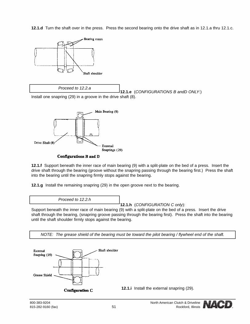
800-383-9204 North American Clutch & Driveline815-282-9160 (fax) 51 Rockford, Illinois
12.1.d Turn the shaft over in the press. Press the second bearing onto the drive shaft as in 12.1.a thru 12.1.c.
12.1.e (CONFIGURATIONS B andD ONLY:)Install one snapring (29) in a groove in the drive shaft (8).
12.1.f Support beneath the inner race of main bearing (9) with a split-plate on the bed of a press. Insert thedrive shaft through the bearing (groove without the snapring passing through the bearing first.) Press the shaftinto the bearing until the snapring firmly stops against the bearing.
12.1.g Install the remaining snapring (29) in the open groove next to the bearing.
12.1.h (CONFIGURATION C only):Support beneath the inner race of main bearing (9) with a split-plate on the bed of a press. Insert the driveshaft through the bearing, (snapring groove passing through the bearing first). Press the shaft into the bearinguntil the shaft shoulder firmly stops against the bearing.
12.1.i Install the external snapring (29).
Proceed to 12.2.a
Proceed to 12.2.h
NOTE: The grease shield of the bearing must be toward the pilot bearing / flywheel end of the shaft.

North American Clutch & Driveline 800-383-9204Rockford, Illinois 52 (fax) 815-282-9160
12.2 Install the Drive Shaft in the Housing
12.2.a (CONFIGURATION A ONLY):Support beneath the bearing housing with the bore up.
12.2.b Install one bearing cup in the bore. (Ifnecessary, gently tap the cup to the bottom of the bore.)
12.2.c Install the shaft and bearing in the bore. DO NOT ADD GREASE AT THIS TIME, but the bearingsshould be lightly oiled.
12.2.d Place the second bearing cup onto the exposed bearing cone. (If necessary, gently tap on the outeredge of the cup to seat the cup against the bearing cone.) Under no circumstances should abusive force beused. Excessive force can damage the roller surface of the bearing cup, causing bearing failure.)
12.2.e Thread the bearing retainer (10) into the bearing housing until it is snugly tightened against the bearingcup. Rotate the drive shaft while tightening the bearing retainer to determine when "zero" bearing clearanceexists. When the bearing cups are seated, the "zero" point will be noted by the increased effort required torotate the drive shaft.
12.2.f After "zero" bearing clearance has been obtained, back the bearing retainer out 2 or 3 notches, usingthe adjustment lock bolt hole as a reference point.
12.2.g Position the adjustment lock (11) tab in a notch, align the bolt hole with the hole in the housing, andinstall the adjustment lock bolt and lockwasher (12 and 13).
12.2.h (CONFIGURATIONS B and D ONLY):Support beneath the bearing housing with the bore up.
NOTE: This is a preliminary adjustment. Final measurement and adjustment will be made in 13.2.
Proceed to 12.3
Configurations B & D: Proceed at 12.2.hConfiguration C: Proceed at 12.2.m

800-383-9204 North American Clutch & Driveline815-282-9160 (fax) 53 Rockford, Illinois
12.2.i Install the shaft in the bore.
12.2.j (Configuration B only):Install the bearing spacer (48) in the bore, against the bearing.
12.2.k Thread the bearing retainer (10) into the bearing housing until it is snugly tightened against the bearingspacer or bearing outer race.
12.2.l Back the bearing retainer off a partial notch if necessary to align the nearest notch with the adjustmentlock (11) tab. Install the adjustment lock bolt and lockwasher (12 and 13).
12.2.m (CONFIGURATION C ONLY:)support beneath the housing with the bore up.
12.2.n Lower the drive shaft and main bearing (output end of the shaft first) to the bottom of the housing bore.The fit should be slightly snug. (Gently tap on the outer race of the bearing if necessary to seat it in the bot-tom of the bore).
12.2.o Securely install the internal snapring (68) in the groove of the bearing housing.
12.3 Install the Cross Shaft and Clutch Release Yoke
Proceed to 12.3
CAUTION: Do not drive the bearing into the housing by tapping on the shaft.To do so may damage the roller surface of the bearing.

North American Clutch & Driveline 800-383-9204Rockford, Illinois 54 (fax) 815-282-9160
12.3.a Lubricate the cross shaft holes in the bell housing. Slide the cross shaft (14) through one hole.
12.3.b Slide the clutch release yoke (17) onto the cross shaft. The bolt holes (unthreaded end) should faceoutward (toward the flywheel). Slide the cross shaft through the release yoke and into the other cross shafthole in the bell housing.
12.3.c Rotate and position the cross shaft so one keyway is exposed in the middle of the release yoke. Theother keyway will be located outside the yoke. Install two woodruff keys (15) in the cross shaft.
12.3.d Slide the cross shaft and woodruff keys into the keyways of the release yoke until the keys are cen-tered on the yoke.
12.3.e Install two bolts and lock washers (18 and 19) in the clutch release yoke. Tighten and torque to:
12.4 Complete the Assembly of the Housing Unit
12.4.a Install all pipe plugs and fittings to complete assembly of the housing.
12.4.b Install remaining fittings in the shaft and housing. (see sections 3.2 and 6.0)
13.0 ADJUST THE MAIN BEARING END PLAY
13.1 (CONFIGURATION B, C and D ONLY):These are ball bearing designs. No adjustment is required.
13.2 (CONFIGURATION A only):
Grade 2 bolts
Grade 5 bolts
17-20 ft-lbs (23 - 27Nm)
26-32 ft-lbs (35 - 43Nm)

800-383-9204 North American Clutch & Driveline815-282-9160 (fax) 55 Rockford, Illinois
13.2.a Support the PTO with a sling and chain hoist as illustrated.
13.2.b Raise the PTO high enough for access to the output end of the drive shaft. Using a soft, but heavymallet against a hard wood block, strike the ended of the shaft to seat the front bearing cup.
13.2.c Lower the PTO and repeat the procedure in 13.2.b on the front end of the drive shaft to seat the rearbearing cup.
13.2.d Insert 4 pieces of shim stock between the shaft and the bearing retainer to fill the gap and minimizesideways movement of the shaft.
13.2.e Attach a dial indicator to a solid bar clamped across the housing as shown. Position the tip of the dialindicator on the nose of the shaft with the direction of indicator tip travel parallel to the shaft. Set the dialindicator to "0".
13.2.f Lower the PTO so the shaft rests on a wood block. Allow a small amount of slack in the lifting strap.Tap lightly on the bell housing to move it downward. Read the dial indicator. The amount of bearing end playwill be indicated.
13.2.g Raise the PTO off the wood block. Lightly tap on the pilot bearing end of the drive shaft to move itdownward against the rear bearing cup.
13.2.h Again read the dial indicator. It should have returned to "0". If it didn't, repeat 13.2.e thru 13.2.g toobtain an accurate reading.
13.2.i If adjustment is necessary, proceed as follows: Rotate the bearing retainer clockwise to decrease or
CAUTION: Sufficient force must be used to securely seat the cups, but abusive force can damage the rollersurface of the cups, resulting in bearing failure.
Main bearing end play should be:(Grease lubricated bearings:)
Configuration A: .004” - .008” (loose)(check with bearings lightly oiled, not greased)
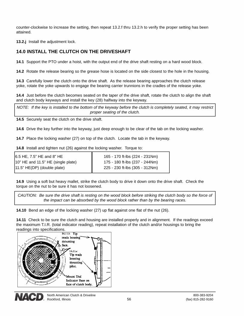
North American Clutch & Driveline 800-383-9204Rockford, Illinois 56 (fax) 815-282-9160
counter-clockwise to increase the setting, then repeat 13.2.f thru 13.2.h to verify the proper setting has beenattained.
13.2.j Install the adjustment lock.
14.0 INSTALL THE CLUTCH ON THE DRIVESHAFT
14.1 Support the PTO under a hoist, with the output end of the drive shaft resting on a hard wood block.
14.2 Rotate the release bearing so the grease hose is located on the side closest to the hole in the housing.
14.3 Carefully lower the clutch onto the drive shaft. As the release bearing approaches the clutch releaseyoke, rotate the yoke upwards to engage the bearing carrier trunnions in the cradles of the release yoke.
14.4 Just before the clutch becomes seated on the taper of the drive shaft, rotate the clutch to align the shaftand clutch body keyways and install the key (28) halfway into the keyway.
14.5 Securely seat the clutch on the drive shaft.
14.6 Drive the key further into the keyway, just deep enough to be clear of the tab on the locking washer.
14.7 Place the locking washer (27) on top of the clutch. Locate the tab in the keyway.
14.8 Install and tighten nut (26) against the locking washer. Torque to:
14.9 Using a soft but heavy mallet, strike the clutch body to drive it down onto the drive shaft. Check thetorque on the nut to be sure it has not loosened.
14.10 Bend an edge of the locking washer (27) up flat against one flat of the nut (26).
14.11 Check to be sure the clutch and housing are installed properly and in alignment. If the readings exceedthe maximum T.I.R. (total indicator reading), repeat installation of the clutch and/or housings to bring thereadings into specifications.
CAUTION: Be sure the drive shaft is resting on the wood block before striking the clutch body so the force ofthe impact can be absorbed by the wood block rather than by the bearing races.
NOTE: If the key is installed to the bottom of the keyway before the clutch is completely seated, it may restrictproper seating of the clutch.
6.5 HE, 7.5” HE and 8” HE10” HE and 11.5” HE (single plate)11.5” HE(DP) (double plate)
165 - 170 ft-lbs (224 - 231Nm)175 - 180 ft-lbs (237 - 244Nm)225 - 230 ft-lbs (305 - 312Nm)

800-383-9204 North American Clutch & Driveline815-282-9160 (fax) 57 Rockford, Illinois
14.11.a Securely support the PTO beneath the rear of the housing with the bell housing and clutch end up.The output shaft end must hang free and be suspended on the bearing races.
14.11.b Mount the base of a dial indicator on the face of the clutch body. Locate the tip on the bell housingmounting face. Slowly rotate the clutch and shaft to read face runout. Maximum runout must not exceed:
14.11.c Move the tip to read the OD of the housing pilot and repeat as in 14.11.b. Maximum runout must notexceed:
14.12 Install the grease hose (greasable release bearing only) through the hole in the side of the housing (if agrease hose is used). Install and tighten the lock nut (6).
14.13 Install the grease fitting (5) in the end of the grease hose (if used).
14.14 Lubricate the PTO. (See sections 3.1, 3.2, and 4.3.)
14.15 Final clutch adjustment may be made after the Power Take-Off is installed on the engine. Refer to sec-tions 3.4 and 3.5 for final clutch adjustment information.
14.16 Refer to section 4.0 for Power Take-Off installation and lubrication instructions.
SAE #1, #2, #3 HousingSAE #4, #5, #6 Housing
SAE #1, #2, #3 HousingSAE #4, #5, #6 Housing
.008” (.203mm)
.006” (.152mm)
.008” (.203mm)
.006” (.152mm)

800-383-9204 North American Clutch & Driveline815-282-9160 (fax) 58 Rockford, Illinois
15.0 TROUBLESHOOTING GUIDE15.1 Common Causes for PTO Failures:
Problem Cause Correction
Clutch slippageNo adjustment or improper
adjustment
Clutch pressure must be set with springpull scale or torque wrench(See section 3.4 and 3.5.)
Clutch slippage(adjustment was properly set)
Glazed, burned or warped matingcomponents from high engagements.
Replace complete clutch with newassembly. Engage with engine speed less
than 1000 RPM. (See section 5.0.)
Clutch slippage(adjustment was properly set)
Clutch disc is oil or grease soaked.Check for proper grease viscosity & lube
intervals. Replace damaged components.(See section 3.0)
Clutch failure(several times)
Clutch does not have torque capacityfor engine output.
Review application.Contact NACD.
Failed release bearing(bronze type)
Improper handle position and/ormodification.
Position handle vertically up or down whenengaged and no pre-load. (See section 4.5)
No output from PTO(clutch feels normal)
Drive teeth worn off clutch disc.Check for failed pilot bearing, misalignment,
and dial indicate bell housing.(See section 2.7)
Failed pilot bearingBearing overloaded, lack of lube,improper bearing for application.
Check for proper belt tension, lubricationand application. (See section 2.4 and 3.0)
Failed main bearing(s)(repeated failures)
Improper application(In-line vs. side load)
Review application.Contact NACD.
Failed main bearing(s)Improper lube intervals, impropergrease, incorrect bearing setting if
applicable.
Checking for proper lubrication, review lubeintervals, set bearings to proper clearance.
(See section 3.0 and 13.0)

LIMITED NACD GENERAL WARRANTY, LIMITATIONS OF REMEDIES ANDLIMITATIONS OF OTHER WARRANTIES
A. North American Clutch and Driveline warrants all assembled products and parts to the original customer. For Power Take-Offs products and parts, such warranty shall extend for a period of fifteen (15) months from the date of original shipment byNACD to the original customer, but not to exceed twelve (12) months of service or one thousand five hundred (1,500) hoursof service, whichever occurs first. The warranty set forth above is exclusive and North American Clutch & Driveline,Inc. makes no other warranty, express or implied. NACD hereby expressly disclaims any and all other warrantiesincluding warranties of merchatability or fitness for a particular purpose.
B. Limitation of Remedies and Liability: The remedies provided herein are buyer’s sole and exclusive remedies. In noevent shall NACD be liable for any direct, indirect, special, punitive, incidental or consequential damages including,but not limited to, loss of revenue or profit, loss of use of the product, cost of capital, cost of substitute equipment orfacilities, cost of cover, downtime costs, claims of any third parties, including buyers’ customers, or any other costswhatsoever, whether based on contract, warranty, tort (including negligence) or any other legal theory.
The above warranty and remedy are subject to the following terms and conditions:
1. Complete parts or products upon request must be returned transportation prepaid and also the claims submitted to NACDwithin sixty (60) days after completion of the in-warranty repair.
2. The warranty is void if, in the opinion of NACD, the failure of the part or product resulted from abuse, neglect, impropermaintenance or accident.
3. The warranty is void if any modifications are made to any product or part without the prior written consent of NACD.4. The warranty is void unless the product or part is properly transported, stored and cared for from the date of shipment to
the date placed in service.5. The warranty is void unless the product or part is properly installed and maintained within the rated capacity of the
product or part with installations properly engineered and in accordance with the practices, methods and instructions approved or provided by NACD.
6. The warranty is void unless all required replacement parts or products are of NACD origin or are NACD authorized replacement parts, and otherwise identical with components of the original equipment. Replacement parts or products not of NACD origin are not warranted by NACD.
C. As considered for this warranty, the original customer and subsequent purchaser agree to indemnify and hold NACD harmlessfrom and against all and any loss, liability, damages or expenses for injury to persons or property, including without limita-tion, the original customer's and subsequent purchaser's employees and property, due to their acts or omissions or the acts oromissions of their agents, and employees in the installation, transportation, maintenance, use and operation of said equipment.
D. Only an NACD authorized factory representative shall have authority to assume any cost or expense in the service, repair orreplacement of any part or product within the warranty period, except when such cost or expense is authorized in advance inwriting by NACD.
E. NACD reserves the right to improve the product through changes in design or materials without being obligated to incorpo-rate such changes in products of prior manufacture. The original customer and subsequent purchasers will not use any suchchanges as evidence of insufficiency or inadequacy of prior designs or materials.
F. If failure occurs within the warranty period, and constitutes a breach of warranty, repair or replacement parts will be furnishedon a no-charge basis and these parts will be covered by the remainder of the unexpired warranty which remains in effect onthe complete unit.
*Note: The Above constitutes the basic NACD General Limited Warranty and may be supplemented by additional publishedwarranty terms dependent upon the product involved. Supplementary warranty terms are available upon request.
North American Clutch & Driveline800-383-9204
Rockford, Illinois

NOTICE
NACD makes no warranty or guarantee of any kind, expressed, implied orotherwise, with regard to the information contained within this manual.NACD assumes no responsibility for any errors that may appear in thismanual and shall not be liable under any circumstances for incidental,
consequential or punitive damages in connection with, or arising out of,the use of this manual. The information contained within this manual is
subject to change without notice.

800-383-9204 North American Clutch & Driveline815-282-9160 (fax) Rockford, Illinois