NonStop Updates and Planned Downtime: CLIM, HSS, HCA …h20628. · 1 P00094-001 . NonStop Updates...
51
1 P00094-001 NonStop Updates and Planned Downtime: CLIM, HSS, HCA and InfiniBand Switch Updates Version 1.0 – 30 June 2017 Part Number P00094-001 Overview There are a number of components residing outside of the NonStop server itself that may require software or firmware updates as a part of planned system downtime. This document provides detailed information about the steps to be followed before coldloading the NonStop system in order to update software and firmware on all the CLIMs and their components. The procedure involves running the ‘Prepare for Down System CLIM Management’ action from the OSM Service Connection, followed by performing the DSM/SCM ZPHIRNM step to complete the host software installation and bring the system down and then invocation of the ‘CLIM Management Tool’ installed in the NonStop System Console (NSC). This document describes how to use NonStop System Console (NSC) based tools to update: • Cluster I/O Modules (CLIM) software and firmware of CLIM components on all the CLIMs present in the NonStop system • Halted State Services (HSS) and InfiniBand HCA firmware in x86 blades (L series only) This document also describes the procedure to upgrade the OS on the NonStop Blade IB Switch. The DSM/SCM ZPHIRNM step is described in the NonStop Software Essentials User Guide. Intended Audience This document is written for those who are planning to perform an RVU upgrade on the J-series and L- series NonStop systems.
Transcript of NonStop Updates and Planned Downtime: CLIM, HSS, HCA …h20628. · 1 P00094-001 . NonStop Updates...

1 P00094-001
NonStop Updates and Planned Downtime: CLIM, HSS, HCA and InfiniBand Switch Updates Version 1.0 – 30 June 2017 Part Number P00094-001
Overview
There are a number of components residing outside of the NonStop server itself that may require software or firmware updates as a part of planned system downtime. This document provides detailed information about the steps to be followed before coldloading the NonStop system in order to update software and firmware on all the CLIMs and their components. The procedure involves running the ‘Prepare for Down System CLIM Management’ action from the OSM Service Connection, followed by performing the DSM/SCM ZPHIRNM step to complete the host software installation and bring the system down and then invocation of the ‘CLIM Management Tool’ installed in the NonStop System Console (NSC).
This document describes how to use NonStop System Console (NSC) based tools to update:
• Cluster I/O Modules (CLIM) software and firmware of CLIM components on all the CLIMs present in the NonStop system
• Halted State Services (HSS) and InfiniBand HCA firmware in x86 blades (L series only)
This document also describes the procedure to upgrade the OS on the NonStop Blade IB Switch.
The DSM/SCM ZPHIRNM step is described in the NonStop Software Essentials User Guide.
Intended Audience
This document is written for those who are planning to perform an RVU upgrade on the J-series and L-series NonStop systems.

2 P00094-001
Update software and firmware of all CLIMs and CLIM components using CLIM Management Tool
The CLIM Management Tool can be used to update firmware/BIOS on the following CLIM components during planned system down time:
• CLIM iLO • CLIM ROM • CLIM Smart Array Controller • CLIM NIC • CLIM InfiniBand HCA • CLIM SAS Firmware • CLIM SAS BIOS • CLIM FC Firmware • CLIM FC BIOS • SAS Disk Enclosure (but not individual SAS disk) Firmware
References The CLIM Management Tool is installed on the NonStop system console (NSC) as part of the OSM Console Tools product, T0634. It requires SSH SPR T0801^ABA or later. For information on installing the CLIM Management Tool, see the NonStop System Console Installer Guide. For information on OSM Service Connection, see the OSM Configuration Guide. For information on the ‘Prepare for Down System CLIM Management’ action, see the OSM Service Connection User's Guide. It is also available as online help within the OSM Service Connection. From within the OSM Service Connection, you can:
• Access a JavaHelp online help interface to the OSM Service Connection User's Guide by selecting Help > Help Contents from the OSM menu bar.
• Get a context-sensitive help topic (from the same JavaHelp interface) by selecting a system resource object, action, or OSM management window area and pressing the F1 key. Help is also available from many dialog box Help buttons.
Detailed instructions
Perform the prepare step from ‘OSM Service Connection’ In the OSM Service Connection, run the action ‘Prepare for Down System CLIM Management’ on the CLIMs object. When you perform the ‘Prepare for Down System CLIM Management’ action, a dialog prompts you to specify:
• The new SYSnn location to be used after the RVU upgrade.
NOTE: This location is the alternate SYSnn on which you installed the SUT containing the new firmware to be used for the update.
• The IP address of the NonStop System Console to which the files will be transferred.

3 P00094-001
• User name and password for the NSC. Click OK to proceed. The Prepare for Down System CLIM Management action collects information on all CLIM firmware/BIOS components whose Compare State is not “Same” or “Compatible” and creates a list of the components that need to be updated. This list along with the actual firmware/BIOS binary files is transferred to specified NSC. The CLIM Management Tool uses this information to perform the firmware/BIOS updates.

4 P00094-001

5 P00094-001
Upon successful completion of the action, the Action Detail window instructs you to perform a ZPHIRNM to complete the installation of the RVU, to bring down the system, and then use the CLIM Management Tool to start the ‘Perform Down System CLIM Software/Firmware Update’ action.
NOTE: CLIMs with iLO-4 firmware versions earlier than 2.42 can get into a bad state. This can cause iLO and/or ROM firmware updates to fail. This can also cause CLIM reboots to fail, which can impact CLIM software updates as well. If the CLIM Management Tool or OSM Service Connection is going to be used to perform any updates to the CLIM's iLO, ROM firmware, or CLIM software, you need to take certain precautions. Please refer to Hotstuff HS03358A for details before proceeding to launch the CLIM Management Tool from the NSC. From the NSC, launch the CLIM Management Tool.

6 P00094-001
Select the system to be updated.
Enter the CLIM Password.

7 P00094-001
Select the version of CLIM software to install.
When the update starts, each row represents the status of one CLIM in the list.
Updates for all the CLIMs are launched in parallel.

8 P00094-001
Updates within each CLIM are done serially.

9 P00094-001
Double Click any row to see the progress of that CLIM.
Individual CLIM progress is seen in a separate window when a row is double clicked.

10 P00094-001
That window does not update in real time.

11 P00094-001
CLIMs are rebooted after the Software update is complete.
Once the CLIMs are back up, all the firmware updates are started.

12 P00094-001

13 P00094-001

14 P00094-001
If there is an error, it will be seen as an error for that CLIM.
Double Click the CLIM row that failed to see which component update failed.

15 P00094-001
In this case, the Embedded NIC firmware update failed.
Other updates passed.
The CLIM will be rebooted after all the updates are completed.
The CLIM will be rebooted even if there is a failure on any of the CLIM components.

16 P00094-001

17 P00094-001
At this point the system can be coldloaded and it will come up with the updated Software and Firmware versions.
Update HSS and HCA on the x86 blades using ‘HSS and HCA Firmware Management Tool’ (L series only)
The HSS and HCA Firmware Management Tool is a console-based OSM interface for managing and updating both HSS and InfiniBand HCA firmware in an x86 blade. This document provides detailed information about the steps to be followed to update HSS and HCA firmware in the x86 blades before coldloading the system.
References For information on installing the HSS and HCA Firmware Management Tool and Halted State Services (HSS) Firmware in the NSC, see the NonStop System Console Installer Guide.
Preparation Collect the following information:
• MEU00 ip address and credentials. • MEU01 ip address and credentials. • Peer NSC ip address and credentials. • DHCP servers’ ip address and credentials, in case DHCP and DNS servers are configured to run in the
CLIM. • Enclosure active Onboard Administrator ip address and credentials.
Steps to be followed
From the NSC, launch the HSS and HCA Firmware Management Tool.

18 P00094-001
Select the ‘Update HSS and HCA Firmware’ option.

19 P00094-001
Enter both ME Unit IP addresses and the MEU credentials, then click Next.

20 P00094-001
Enter credentials for the Peer NSC and click Next.

21 P00094-001
The tool asks for the DHCP and DNS servers' IP address and credentials only if they are configured to run in the CLIM. In this case, enter the IP address and credentials of the DHCP servers and then click Next.

22 P00094-001
Enter the Enclosure active Onboard Administrator IP address and credentials, then click Next.

23 P00094-001
The tool displays the list of HSS versions available in the NSC. Select the HSS version to be installed in the x86 blades and click ‘Update HSS and HCA’ to continue. The HCA version is automatically picked up by the tool for the selected HSS distribution. The processors will be halted and hard reset as part of this update.

24 P00094-001

25 P00094-001

26 P00094-001

27 P00094-001

28 P00094-001
At this point the system can be coldloaded and it will come up with the updated HSS and HCA Firmware versions.
Updating the OS on the NonStop Blade IB Switches (L series)
This section provides detailed information on how to upgrade the OS on the NonStop Blade IB switches. Updating the OS automatically updates the firmware on the blade IB switch. The IB switches can be updated serially even when the system is up. The procedure involves running certain actions from the ‘OSM Service Connection’ to ensure that the internal IB fabric that becomes the active path performs properly.
References To determine the supported firmware version for L-series RVU (for example, version 3.4.0008 for L15.08), see the NonStop Firmware Matrices. The firmware used on Blade IB switches is not controlled on the SUT, so the firmware on the IB switch must first be verified through the InfiniBand switch interface. If you need to update this firmware, be sure you install the supported firmware version for your current L-series RVU (for example, version 3.4.0008 for L15.08). The latest firmware versions provided on the NSC DVD are identified in the NonStop Firmware Matrices. For information on OSM Service Connection, see the OSM Configuration Guide. For more information on Nonstop Blade IB switch, see the ‘Mellanox MLNX-OS® InfiniBand User Manual for HP’. This manual is available in the web interface of the InfiniBand switch. From the web interface, select Product Documents>User Manual to access the manual.
Prepare the System for updating the OS on the NonStop Blade IB Switch Perform these steps: 1. Use the OSM Service Connection ‘InfiniBand Path Test’ action to test the internal IB fabric that
becomes the active path while the other Blade IB switch is upgraded to ensure this fabric performs properly:
• If you are upgrading the Blade IB switch in c7000 enclosure bay 5 or 6, test the System>Internal
InfiniBand Y fabric. Run the ‘InfiniBand Path Test’ action available on Internal InfiniBand Y fabric under the System object.
• If you are upgrading the Blade IB switch in c7000 enclosure bay 7 or 8, test the System>Internal InfiniBand X fabric. Run the ‘InfiniBand Path Test’ action available on Internal InfiniBand X fabric under the System object.
Identify and fix any problems detected by the test before continuing with the Blade IB switch upgrade procedure.

29 P00094-001
NOTE: C7000 enclosure Bays 5 and 6 are associated with IB switches for the X Fabric. Bays 7 and 8 are associated with IB Blade switches for the Y Fabric.
2. Because all interprocessor traffic within the local node goes through the Blade IB switches, perform the
Interprocessor Path Test to test and validate the interprocessor path (X or Y) to ensure that it will successfully become the sole active interprocessor path when you upgrade the Blade IB switch
• If you are upgrading the Blade IB switch installed in bay 5 or 6 of the c7000enclosure, run the
‘Processor-to-Processor Connectivity Test’ action available on Internal InfiniBand Y fabric under the System object.
• If you are upgrading the Blade IB switch installed in bay 7 or 8 of the c7000 enclosure, run the ‘Processor-to-Processor Connectivity Test’ action available on Internal InfiniBand X fabric under the System object.
3. If the system is connected to a NonStop X Cluster Solution, perform these steps:
a. From the OSM Service Connection, click on the Display>Multi-Resource... action. b. Select Remote Node under Resource Types. c. Select ‘Interprocessor Path Test on X/Y Fabric’ from the Action drop down menu. d. Click on Add All. e. Click on Perform Action. f. Fix any problems that are detected by the test before continuing with this upgrade procedure. g. Select the ‘Place Local Node in Service’ action on the InfiniBand Cluster object. h. Check for Cluster Connectivity Problems
Before you begin the process of upgrading a Blade IB switch in a cluster node, issue this command to test for connectivity problems within the cluster: 1–> SCF STATUS SUBNET $ZZCMN, PROBLEMS SCF — T9082L01 — (18 SEP15) (31SEP15) — 10/10/2015 13:53:53 System \HOME01 (C) Copyright 1986–2014 Hewlett-Packard Development Company L.P. Node Sysname Nodes With Connectivity Problems - — — — — — — — — — — — — — — — – — — — — — — — — — — — — — – — — — — — — — 61) \BLOSM1 | ) No connectivity problems detected ) 62) \BLOSM3 | ) No connectivity problems detected ) 107) \BLOSM3 | ) No connectivity problems detected ) Total Errors = 0 Total Warnings = 0 2 — > If the test returns connectivity errors, do the following before continuing with this service procedure: • Locate and repair all reported connectivity problems. • Repeat this connectivity test to ensure that no connectivity problems are detected.
CAUTION: The Local Node provides the only connection to other zones in a cluster. Fix any problems detected by the test before continuing with this upgrade procedure.
4. Use the OSM ‘Suppress Problem Incident Report Creation’ action on the System object to prevent
unnecessary dial-out communications related to the Blade IB switch.

30 P00094-001
Steps to be followed NOTE: This procedure starts with the assumption that Partition 1 is the active partition and you need to load Partition 2, the inactive partition, and the screen captures provided reflect this. If Partition 2 is the active partition, perform these steps accordingly, treating Partition 1 as the inactive partition. Where instructed, boot the active partition and repeat the procedure for the other partition. 1. Logon to the IB switch web interface using default static IP address for the switch’s rack location and
logon with the username ‘admin’ and the password ‘admin’. 2. From the web interface, select System>MLNX-OS Upgrade. 3. Verify that both partitions eventually display the correct firmware version the current L-series RVU as
specified in the NonStop Firmware Matrices. This GUI window shows that Partition 1 is currently the active partition running on the switch.

31 P00094-001
4. If the installed firmware version that is displayed (for example, the SX_3.4.008 value shown in the
preceding GUI window) is not the firmware version identified for your current L-series RVU in the NonStop Firmware Matrices, perform these actions in the Install New Image to (non-active) Partition 2 section:
a. Select the ‘Install from local file’ option. b. From the NSC DVD, navigate to C:\NonStop Firmware and select the folder for your L-series
RVU. c. Select the .img file version for your L-series RVU that is specified in the NonStop Firmware
Matrices:
image-PPC_M460EX_x.y.000z.img
d. Select ‘View image upgrade progress’.

32 P00094-001
e. Under Image validation, pull-down the ‘Validate if signature present’ option. f. Select the Install Image button.

33 P00094-001
5. Initially, this Loading icon will display in the window.
34 P00094-001
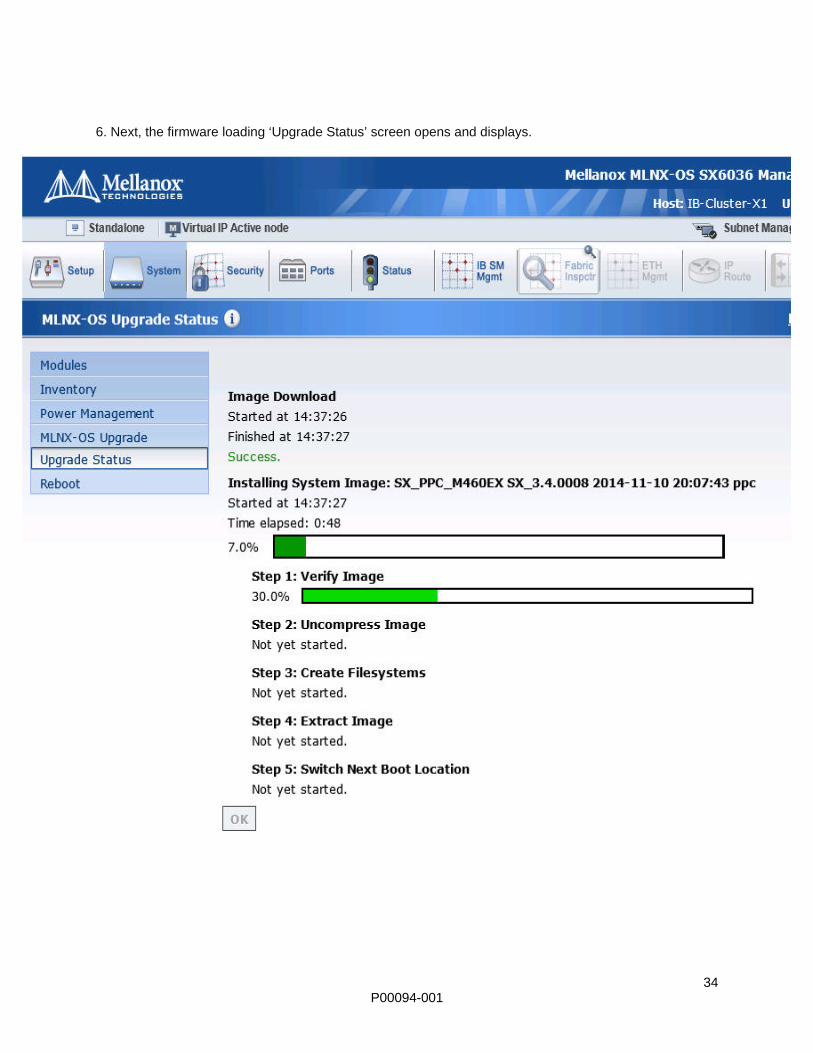
6. Next, the firmware loading ‘Upgrade Status’ screen opens and displays.
35 P00094-001
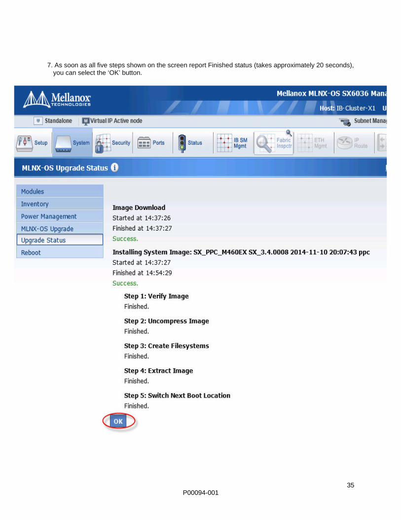
7. As soon as all five steps shown on the screen report Finished status (takes approximately 20 seconds), you can select the ‘OK’ button.

36 P00094-001
8. Select the ‘Reboot’ option in the System menu. When the following message appears, select the
‘Reboot’ option again.
9. If the following Warning! message alerts you to saving the InfiniBand switch configuration, select
‘Cancel’ to save those changes.

37 P00094-001
10. When the following Warning! screen appears, select the ‘Reboot’ option again to confirm that you
want to reboot.

38 P00094-001
11. The following log out screen will appear. When it does, monitor the InfiniBand switch’s LEDs. As soon as the LEDs for the occupied ports are all illuminated (it normally takes about 10 minutes), this signifies that the switch is active again. When this happens, select the ‘click here’ link.

39 P00094-001
12. Log on to the switch using the Account name ‘admin’ and the password ‘admin’.

40 P00094-001
13. When this End User License Agreement displays, select ‘Confirm’.
14. Navigate to the System>MLNX-OS Upgrade screen.
The following screen shot confirms that Partition 2 has been successfully loaded.

41 P00094-001
15. Repeat firmware update steps 1 through 3, but this time enter the data within the Install New Image to
(non-active) Partition 1 area.

42 P00094-001
16. After you have successfully completed the firmware update procedure for both partitions, navigate to the System>MLNX-OS Upgrade screen again. Verify that both partitions now report the latest supported L-series switch firmware version as specified in the NonStop Firmware Matrices.
17. Reboot the Blade IB switch to make sure it can run on Partition 1. 18. Perform SNMP Setup:
NOTE: OSM will automatically attempt to monitor Blade IB switches with a default Read-Only Community string of public, a default Read-Write Community string of private, and a default Default Notification Community string of public. If you use all of these default settings for the Blade IB switch, you do not have to perform the ‘Configure SNMP Credentials’ action described in “Configuring SNMP Credentials” step.

43 P00094-001
19. To set the SNMP settings, perform these steps from this screen at the start of the SNMP>Setup configuration displays in the Mellanox Management Console GUI (see the yellow highlighted screen options):
a. Unselect the ‘Enable Multiple SNMP Communities’ checkbox. b. Click on ‘Apply’.

44 P00094-001
c. Select the Enable SNMP checkbox. d. Select the Enable SNMP communities checkbox. e. Select the Enable SNMP Notification (Traps and Informs) checkbox. f. Set SNMP Agent Port to 161. g. Set Read-Only Community to public. h. Set Read-Write Community to private. i. Set Default Notification Community to public. j. Set Default Notification Port to 162. k. Click Apply.

45 P00094-001
20. To configure the switch to send SNMP traps to $ZTCP0 (192.168.36.10 by default), scroll further down the Setup>SNMP display until you see Add New Notification Sink and do the following (see the yellow highlighted options):

46 P00094-001
a. Set Address to 192.168.36.10 (by default). b. Set the Enable checkbox. c. Set Notification Type to vltrap. d. Click on the Add New Sink button.
21. To configure the switch to send SNMP Traps to $ZTCP1 (192.168.36.11 by default), scroll further
down the Setup>SNMP display until you see Add Notification Sink and do the following:
a. Set Address to 192.168.36.11 (by default). b. Set the Enable checkbox. c. Set Notification Type to vltrap. d. Click on the Add New Sink button.

47 P00094-001
22. To make sure that 192.168.36.10 and 192.168.36.11 are in the list in the Notification Sinks: SNMP v1 and v2c section, scroll further down and do the following (see the yellow highlighted options):
a. Under Notification Sinks: SNMP v1 and v2c, confirm that both 192.168.36.10 and 192.168.36.11
are in the list as shown. b. Click on the Save button to save these changes.
23. Configuring SNMP Credentials This section describes how to configure SNMP credentials on the upgraded Blade IB switch if the saved configurations have been lost by the switch. Obtain the expected credential settings, and then perform the following steps to configure SNMP credentials for Blade IB switch only if the expected credentials had been configured as follows:

48 P00094-001
• Read-Only Community string on the Blade IB switch to something other than public • Read-Write Community string on the Blade IB switch to something other than private • Default Notification Community string on the Blade IB switch to something other than public
If the Blade IB switch is so configured, perform these steps:
a. From OSM, perform the Configure SNMP Credentials action on the System>Enclosure>Internal InfiniBand Switch object.
b. Set the Public Community String to what was set in the Blade IB switch SNMP’s Read-Only Community” configuration.
c. Set the Private Community String to what was set in the Blade IB switch SNMP’s Read-Write Community configuration.
d. Set the Public Community String for Traps to what was set in the Blade IB switch SNMP’s Default Notification Community configuration.
24. Use the OSM Service Connection Alarm Summary function on the upgraded Blade IB switch to check for any alarms.
25. Use the OSM InfiniBand Path Test action to test the affected IB fabric: • For a Blade IB switch in c7000 enclosure bay 5 or 6, use the InfiniBand Path Test action on the
System>Internal InfiniBand X Fabric object. • For a Blade IB switch in c7000 enclosure bay 7 or 8, use the ‘InfiniBand Path Test’ action on the
System>Internal InfiniBand Y Fabric object. 26. Because all interprocessor traffic goes through the Blade IB switches, perform the Interprocessor
Path Test to test and validate the interprocessor path (X or Y) within the local node when you upgraded the Blade IB switch: • If you upgraded the Blade IB switch installed in bay 5 or 6 of the c7000 enclosure, run ‘Processor-
to-Processor Connectivity Test’ action available on Internal InfiniBand X fabric under System object.
• If you upgraded the Blade IB switch installed in bay 7 or 8 of the c7000 enclosure, run ‘Processor-to-Processor Connectivity Test’ action available on Internal InfiniBand Y fabric under System object.

49 P00094-001
27. Use the OSM ‘Unsuppress Problem Incident Report Creation’ action on the system object to again allow dial-out communications.
Summary This section has the average time taken to update:
• CLIM software and firmware of CLIM components NOTE: Average time stated are for Gen8 and Gen9 Network (NCLIM) and Storage (SCLIM) CLIMs. However, these timings might vary between systems and individual CLIMs.
• Halted State Services (HSS) and InfiniBand HCA firmware in x86 blades • OS on NonStop Blade IB switch
Component Average Time taken with
100MB/S Switch Average Time taken with 1GB/S
Switch
CLIM SW Update time
(16 NCLIMs & 10 SCLIMs)
22 minutes 6.5 minutes for NCLIM
8.5 minutes for a SCLIM
Longest SW Update time 24 minutes
(was a storage CLIM)
8 minutes for NCLIM
10 minutes for a SCLIM
Reboot Time Average 6 minutes 4 minutes for NCLIM
6 minutes for SCLIM
Longest Reboot time 11 minutes
(was a storage CLIM)
5 minutes for NCLIM
9 minutes for SCLIM
Average Time taken for iLO update
6 minutes
(Longest 9 minutes)
5 minutes
(Longest 6 minutes)
Time taken for ROM update 2 minutes 1.5 minutes

50 P00094-001
Time taken for NIC update 4 minutes for most updates (Longest 6 minutes)
1 to 5 minutes depending on type of NIC
Time taken for SAS HBA BIOS update
1 minute 1 minute
Time taken for SAS HBA Firmware update
1 minute 1 minute
Time taken for FC Card update
2 minutes 2 minutes
Time taken for Smart Array Controller update
1 minute 1 minute
Time taken for HCA update 1 minute 1 minute
Time taken to complete Software and Firmware
Update on Network CLIMs (16 CLIMs)
55 minutes 27 minutes
Time taken to complete Software and Firmware
Update on Storage CLIMs (10 CLIMs)
51 minutes 34 minutes

51 P00094-001
Copy HSS 30 seconds
HCA UPDATE and Reset 12 minutes
4 IB Switch FW upgrades Time = 23 minutes for each partition
- upgrade: 15 minutes
- reboot: 8 minutes
Total time (2 partitions) = 46 minutes
NOTE: Upgrade times stated are for a single revision level update. Any updates that require multiple revision level updates will require more time.