Nonlinear dynamics of a vehicle with a displacement ... · it possible to effectively analyse the...
18
Nonlinear Dyn (2020) 100:185–202 https://doi.org/10.1007/s11071-020-05532-7 ORIGINAL PAPER Nonlinear dynamics of a vehicle with a displacement-sensitive mono-tube shock absorber Jan Luczko · Urszula Ferdek Received: 21 February 2019 / Accepted: 11 February 2020 / Published online: 24 February 2020 © The Author(s) 2020 Abstract The paper presents a new concept of absorb- ing car body vibrations, which consists in a modifi- cation of the construction of the classical mono-tube hydraulic shock absorber by the introduction of an additional inner cylinder with an auxiliary piston. By making an appropriate selection of the system parame- ters, one may obtain the damping force characteristics dependent on the excitation amplitude and frequency. In the case of driving on a good-quality road surface, the shock absorber displays the soft characteristics which are desired as far as the driving comfort is concerned. In the case of worse-quality roads or while overcoming large obstacles, the hard characteristics ensure a higher level of safety and protect the shock absorber from get- ting damaged. The developed nonlinear model makes it possible to effectively analyse the system responses to harmonic, impulse and random excitations. On the basis of the analysis of the impact of harmonic exci- tations on the driving comfort and safety indexes, one may estimate the optimal values of the shock absorber construction parameters. Impulse and random excita- tions are applied in order to finally verify the effective- ness of the operation of the proposed shock absorber. J. Luczko · U. Ferdek (B ) Politechnika Krakowska im. Tadeusza Kosciuszki, Jana Pawla II 37, 31-864 Kraków, Poland e-mail: [email protected] J. Luczko e-mail: [email protected] Keywords Hydraulic damper · Shock absorber · Nonlinear vibrations · Vehicle suspension 1 Introduction The constructions of modern car vehicles suspensions undergo changes together with the development of technology. The shock absorber is one of the suspen- sion elements responsible for minimizing car body displacements, and in this way responsible for the driving safety and comfort. One may list numerous designs of car shock absorbers, starting with the sim- plest hydraulic ones with constant characteristics of the damping force, to the most complex active ones in which the damping force is dependent on a type of the road surface. Until recently, due to a high level of reliability and low exploitation costs, passive shock absorbers with a classical construction were most fre- quently used as the principle of their operation is rela- tively simple. Such shock absorbers contain springy and damping elements of nonlinear characteristics. Depending on the construction of flow channels, a shock absorber may possess the so-called soft or hard characteristics. The so-called hard suspensions ensure better vehicle driving but, at the same time, they lower the passenger ride comfort. In order to find a compromise one more and more frequently applies active or semi-active shock absorbers, e.g. magnetorheological ones [1–3], whose characteristic adjusts to a type of the driven road sur- 123
Transcript of Nonlinear dynamics of a vehicle with a displacement ... · it possible to effectively analyse the...

Nonlinear Dyn (2020) 100:185–202https://doi.org/10.1007/s11071-020-05532-7
ORIGINAL PAPER
Nonlinear dynamics of a vehicle with adisplacement-sensitive mono-tube shock absorber
Jan Łuczko · Urszula Ferdek
Received: 21 February 2019 / Accepted: 11 February 2020 / Published online: 24 February 2020© The Author(s) 2020
Abstract Thepaper presents a newconcept of absorb-ing car body vibrations, which consists in a modifi-cation of the construction of the classical mono-tubehydraulic shock absorber by the introduction of anadditional inner cylinder with an auxiliary piston. Bymaking an appropriate selection of the system parame-ters, one may obtain the damping force characteristicsdependent on the excitation amplitude and frequency.In the case of driving on a good-quality road surface, theshock absorber displays the soft characteristics whichare desired as far as the driving comfort is concerned.In the case of worse-quality roads or while overcominglarge obstacles, the hard characteristics ensure a higherlevel of safety and protect the shock absorber from get-ting damaged. The developed nonlinear model makesit possible to effectively analyse the system responsesto harmonic, impulse and random excitations. On thebasis of the analysis of the impact of harmonic exci-tations on the driving comfort and safety indexes, onemay estimate the optimal values of the shock absorberconstruction parameters. Impulse and random excita-tions are applied in order to finally verify the effective-ness of the operation of the proposed shock absorber.
J. Łuczko · U. Ferdek (B)Politechnika Krakowska im. Tadeusza Kosciuszki, JanaPawła II 37, 31-864 Kraków, Polande-mail: [email protected]
J. Łuczkoe-mail: [email protected]
Keywords Hydraulic damper · Shock absorber ·Nonlinear vibrations · Vehicle suspension
1 Introduction
The constructions of modern car vehicles suspensionsundergo changes together with the development oftechnology. The shock absorber is one of the suspen-sion elements responsible for minimizing car bodydisplacements, and in this way responsible for thedriving safety and comfort. One may list numerousdesigns of car shock absorbers, starting with the sim-plest hydraulic ones with constant characteristics ofthe damping force, to the most complex active onesin which the damping force is dependent on a typeof the road surface. Until recently, due to a high levelof reliability and low exploitation costs, passive shockabsorbers with a classical construction were most fre-quently used as the principle of their operation is rela-tively simple. Such shock absorbers contain springyand damping elements of nonlinear characteristics.Depending on the construction of flow channels, ashock absorber may possess the so-called soft or hardcharacteristics. The so-called hard suspensions ensurebetter vehicle driving but, at the same time, they lowerthe passenger ride comfort.
In order to find a compromise one more andmore frequently applies active or semi-active shockabsorbers, e.g. magnetorheological ones [1–3], whosecharacteristic adjusts to a type of the driven road sur-
123
186 J. Łuczko, U. Ferdek
face. However, due to a considerably more complexconstruction they are more expensive to produce andexploit than passive shock absorbers. For these reasons,manufacturers develop more and more modern passiveshock absorbers with modified constructions, whosecharacteristics possess similar properties as in the caseof active shock absorbers.
One of such designs is the hydraulic damper with anadditional flow channel (bypass), controlled by a rela-tive displacement of the piston [4,5]. For large ampli-tudes of excitations (worse roads), the modified con-struction of the shock absorber ensures a similar levelof safety as in the case of hard shock absorbers. Duringthe trip on a good-quality road surface, i.e. in the caseof lower amplitudes of excitations, the characteristic ofthe damping force of the shock absorber with a bypassis similar to the one present in the soft shock absorber,thus resulting in better driving comfort. Therefore, thecharacteristic of the shock absorber with a bypass isdependent on the amplitude of excitation. A sampledesign for shock absorber with bypass is proposed byLee and Moon [5]. The additional flow between thecompression chamber and the rebound chamber is real-ized by an appropriate shape of the cylinder’s innersurface.
A series of other shock absorbers with innovativeconstructions [6–8] may also be classified within thegroup of hydraulic dampers with a variable character-istic of the damping force. One of them is a twin-tubehydraulic shock absorberwith an additional inner cylin-der presented in the paper [6]. The characteristic of thedamping force depends on the amplitude of excitationsince the flow of oil between the chambers of the mainand the inner cylinder is controlled by the displacementof the auxiliary piston.
In order to analyse the effectiveness of the opera-tion of shock absorbers, one most frequently appliestwo-mass, the so-called quarter-car models [2,4,6,9].One of the masses, the so-called sprung mass, repre-sents the car body, whereas the other one (un-sprungmass) represents the wheel with appropriate suspen-sion elements. The quarter-car model allows for carry-ing out a dynamic analysis of the system in two res-onance ranges, which are important from the point ofview of the driving comfort and safety. The drivingcomfort depends on the level of vibrations of the car’sbody. Typically, the RMS (root mean square) of thedisplacement or acceleration of the sprung mass is themeasure of the comfort [10,11], which reaches a max-
imum value in the first resonance range. Vibrations ofthe un-sprung mass are dominant within the range ofhigh frequencies. Within this range, the momentaryforces of the wheel pressure on the road surface aredecreased, which in turn impacts driving safety. Thedynamic component of the reaction [11] or its minimalvalue and the associated EUSAMA indicator [9] arefrequently applied as the safety index.
The level of vibration felt by the driver depends to alarge extent on the road surface and the speed driving.Various realizations of stochastic processes are used todescribe the road profile [12–15]. During the designprocess, harmonic excitations with constant or vari-able frequency are also useful for that purpose. Typi-cally a constant amplitude of the excitation is used, butit is better to assume that the amplitude is a decreas-ing function of frequency. This approach is proposedby Funke [16], which assumes a constant value of themaximum speed of excitation, so that the amplitude isa function inversely proportional to the frequency.
In recent years, there have appeared more and morevarious kinds of speed breakers on roads in the areaswhere extra caution is required, e.g. in places withintense pedestrian traffic or near schools. The purposeof implementing such solutions is to force drivers toconsiderably reduce the driving speed. Impulse func-tions [17], e.g. of a unit step type, are used to describethis kind of excitations. The implementation of shockabsorbers with adjustable characteristics of the damp-ing force in the suspension system makes it possibleto overcome unevenness of an impulse character whilemaintaining the highest possible driving comfort.
There are many works in the literature devotedto modelling and analysis of both twin-tube shockabsorbers [4,16,18–20] and mono-tube shockabsorbers [21–24]. However, most of them considerclassic constructions, in which the oil flow between thecompression and rebound chambers takes place underthe influence of the oil pressure difference only throughthe channels in the main piston. Frequently the orificesof the channels are assumed to be covered by a stack ofcircular plates, and the details of their modelling can befound, e.g. in the works of Alonso [18], Farjoud [23]and Talbott [24]. The vibration of valves and the occur-ring acoustic discomfort is analysed by Benazis in thepaper [25].
A new design of the mono-tube hydraulic shockabsorber, definitely different frommost of the classicalconstructions discussed in the available literature, has
123
Nonlinear dynamics of a vehicle 187
been proposed in this paper. Although this construc-tion has some similarities to the shock absorber shownin the paper [6], its operating principle is quite differ-ent. Both solutions have an additional inner cylinderwith an auxiliary piston, but the role of the piston ineach of them is different. In the considered work [6],the variable shock absorber characteristic is the effectof the flows between the chambers of the inner cylin-der and the compression or rebound chamber. In theshock absorber presented in this paper, an auxiliarypiston directly controls the oil flow between the com-pression and the rebound chamber. In addition, thecurrently proposed solution is applied to a mono-tubeshock absorber,whereas themodel of a twin-tube shockabsorber is previously tested. The results of numericalsimulations of vibration damping of the vehicle bodypresented in the paper confirm the effectiveness of theproposed shock absorber.
2 Model of the system
2.1 Model of the hydraulic shock absorber
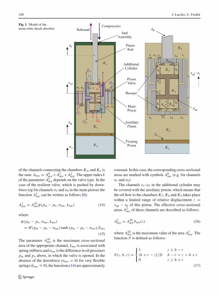
A model of the studied shock absorber is illustrated inFig. 1. Themain element of the classical shock absorberis the tube known as the working cylinder, connectedto the vehicle suspension (so-called un-sprung mass).
The working cylinder consists of two chambers: therebound chamber K1 and the compression chamber K2,which separates the main piston. The main piston isconnected by the piston rod to the car body, i.e. thesprungmass. In the working cylinder, there is a floatingpiston which separates the chamber K2 filled with oilfrom the chamber K6, filledwith high pressure nitrogen(approx. 2 MPa).
In the proposed concept of the shock absorber, thereis an additional cylinder which is rigidly fixed with thepiston rod. Inside this cylinder, there is an appropriatelyshaped auxiliary piston,which divides this cylinder intothe chambers K3 and K4 of a variable volume, and thechamber K5 of a constant volume.
The oil flow between the chambers K1 and K2 takesplace through the channels which are always open (o1and o2, Fig. 1) and covered with low-stiffness plates(o3 and o4), the flow between the chambers of the addi-tional cylinder is via c1–c9 channels.
In order to determine oil pressures in the chambersKn (n = 1, 2, . . . , 5), the following equation may beused [6]:
pn = β
[Qn
mn− Vn
Vn
](1)
where mn are the oil mass in the chambers Kn (n =1, 2, . . . , 5), while β stands for the compressibilitymodulus. The volumes Vn of the chambers Kn areexpressed by the formulae:
V1 = V10 − Atp(xb − xw) (2)
V2 = V20 + Ap(xb − xfp) (3)
V3 = V30 − Aap(xap − xb) (4)
V4 = V40 + Aap(xap − xb) (5)
V5 = V50 (6)
The parameters Vn0 constitute the initial volumes of thechambers Kn , and the parameters Atp = Ap − Apr, Ap
and Aap determine the upper and lower surface of themain piston, respectively, as well as the surface of theauxiliary piston.
The change of the oil mass in the chambers Kn isdefined by the equation:
mn = Qn (7)
where
Q1 = Q21 − Q12 + Q31 − Q13 + Q51 − Q15 (8)
Q2 = Q12 − Q21 + Q42 − Q24 + Q52 − Q25 (9)
Q3 = Q13 − Q31 (10)
Q4 = Q24 − Q42 (11)
Q5 = Q25 − Q52 + Q15 − Q51 (12)
where Qmn is mass flow rate from the chamber Km
(m = 1, 2, . . . , 5,m �= n) to the chamber Kn . In thecase of a turbulent flow [26], the flow rate Qmn is deter-mined from the formula:
Qmn = CdAmnH(pm − pn)√2ρm |pm − pn| (13)
where the parameterCd is the discharge coefficient andAmn is an effective cross-sectional area of an appro-priate channel. The function H () of the unit step typeensures that the condition: Qmn = 0 for pm < pn isfulfilled.
The oil flow control usually depends on the differ-ence in oil pressures in the adjacent chambers, andin some cases in addition to the relative displacementz = xap − xb of the auxiliary piston. We assume that inthe general case the total effective cross-sectional area
123
188 J. Łuczko, U. Ferdek
Fig. 1 Model of themono-tube shock absorber
of the channels connecting the chambers Km and Kn isthe sum: Amn = A0
mn + A1mn + A2
mn . The upper index kof the parameter Ak
mn depends on the valve type. In thecase of the resilient valve, which is pushed by down-force (eg for channels o3 and o4 in the main piston) thefunction A1
mn can be written as follows [6]:
A1mn = A10
mnφ(pm − pn, σnm, knm) (14)
where
φ(pm − pn, σmn, kmn)
= H(pm − pn − σmn) tanh (pm − pn − σmn)/kmn
(15)
The parameter A10mn is the maximum cross-sectional
area of the appropriate channel, kmn is associated withspring stiffness andσmn is the difference in oil pressurespm and pn above, in which the valve is opened. In theabsence of the downforce (σmn = 0) for very flexiblesprings (kmn ≈ 0), the functions (14) are approximately
constant. In this case, the corresponding cross-sectionalareas are marked with symbols A0
mn (e.g. for channelso1 and o2).
The channels c1–c5 in the additional cylinder maybe covered with the auxiliary piston, which means thatthe oil flow to the chambers K3, K4 and K5 takes placewithin a limited range of relative displacement z =xap − xb of this piston. The effective cross-sectionalareas A2
mn of these channels are described as follows:
A2mn = A20
mnϑnm(z) (16)
where A20mn is the maximum value of the area A2
mn . Thefunction ϑ is defined as follows:
ϑ(z, h, r) =⎧⎨⎩1 z � h − r(h + r − z)/2r h − r < z < h + r0 z � h + r
(17)
123

Nonlinear dynamics of a vehicle 189
Fig. 2 Quarter-car model
where the parameters h and r determine the positionof orifices and their radii. For the proposed system(Fig. 1), the functions ϑ51(z) = ϑ(−z, h1, r1) andϑ31(z) = ϑ(z, h2, r2) describe the process of cov-ering the channels connecting the chamber K1 withthe chamber K5 (c1, c2) and K3 (c4), respectively.By analogy, the functions ϑ52(z) = ϑ(z, h1, r1) andϑ42(z) = ϑ(−z, h2, r2) describe the flow between thechambers K2 and K5 (c3) as well as K2 and K4 (c5).
Apart from the valves controlled by relative dis-placement, in the chambers K3 and K4 there are alsochannels which are always open (c8, c9) and coveredwith low-stiffness plates (c6, c7). In order to describethe oil flow through the channels c6 and c7, the formula(14) may be used. Ultimately, for m = 3 and n = 1,m = 5 and n = 1, m = 4 and n = 2, m = 5 andn = 2 (analogically for the flows in reverse direction)the total effective cross-sectional areas are described bythe formula Amn = A0
mn + A1mn + A2
mn . The effectivecross-sectional areas of the channels in the main piston(for m = 1, n = 2 or m = 2, n = 1) are the sum:Amn = A0
mn + A1mn .
Equations (1–17) determine pressure changes in thechambers Kn (n = 1, 2, . . . , 5). Gas pressure in thechamber K6 may be determined after accepting the adi-abatic process from the equation:
p6 = p0V κg0
[Vg0 + Ap(xfp − xw)]κ (18)
where κ is the adiabatic index, and Vg0 is the initial gasvolume (in the state of equilibrium).
2.2 Quarter-car suspension model
In order to test the effectiveness of vibration, dampingthequarter-carmodel of the vehicle shouldbe examined(Fig. 2). Assuming that the coordinates: xw, xb, xfp, xapdetermine themovement of the un-sprungmassmw andthe sprung mass mb as well as floating piston mfp andthe auxiliary pistonmap, the vibrations around the equi-librium can be described by the system of four second-order differential equations in the following form:
mw xw = kb(xb − xw) + kw(xr − xw) + Fw (19)
mb xb = −kb(xb − xw) − Fb + Fbump (20)
mfp xfp = (pg − p2)Ap − Ffpsgn(xfp − xw) (21)
map xap = (p4 − p3)Aap + kap(xb − xap) − Fbump
(22)
The parameters kw and kb and kap are the stiffness ofthe tyre and the spring, respectively, while kap is thestiffness of the mounting of additional mass. Nonlin-ear forces Fb and Fw are expressed with the followingformulae:
Fw = (p1−p0)Atp − (pg−p0)Ap+Fp sgn(xb − xw)
+ Ffp sgn(xfp − xw) (23)
Fb = (p1 − p0)Atp − (p2 − p0)Ap + (p4 − p3)Aap
+ Fp sgn(xb − xw) + kap(xb − xap) (24)
where Fp and Ffp are friction forces between the pistonrod and the guideway [4] aswell as between the floatingpiston and the cylinder, respectively. The force Fbump,which describes the impact of the bumpers, is definedas follows:
Fbump=⎧⎨⎩kbump(xap−xb − h3) xap−xb � h30 −h3 < xap−xb < h3kbump(xap−xb + h3) xap−xb � −h3
(25)
Owing to the fact that the displacements are mea-sured with respect to the static equilibrium, the forcekw(xr − xw) describes only the dynamic component ofthe reaction affecting the car wheel. In the case of per-manent contact of car wheels with a road surface thesum of the static (mw + mb)g and dynamic reactionsshould be higher than zero, and hence the conditionkw(xr − xw) + (mw + mb)g > 0 should be fulfilled.Therefore, the lowest possible values |kw(xr − xw)| arerecommended for reasons of the driving safety.
123

190 J. Łuczko, U. Ferdek
2.3 Modelling of a road profile
Depending on the purpose of the research, the road pro-file can be described by harmonic, impulse or randomfunctions. Harmonic excitations are particularly usefulin studying the impact of construction parameters onthe efficiency of the shock absorber. In such analyses,it is advisable to assume that the amplitude depends onthe frequency of excitation [6].
For a constant amplitude and higher frequencies,wheels can detach from the road surface (contact losscondition: kw(xr − xw) + (mw + mb)g < 0, whichusually does not happen in reality. In the case of a roadwith aworse surface (for larger amplitudes), the drivingspeed should be lower, which is also associated with alower frequency of excitation. We will assume furtherexcitation in the form of:
xr(t) = (a0 f0/ f ) sin 2π f t (26)
where a0 is the amplitude of the excitation for the fre-quency f = f0. From the formula (26) follows thecondition: xmax
r (t) = 2π f0a0 = const.Impulse excitations of various types are applied in
order to describe excitations arising while a vehicleis overcoming obstacles. It is convenient to use forthis purpose the ‘rounded pulse’ function [6] whichis defined as follows (Fig. 3):
xr(s) = He2ξ2 exp(−2ξ) (27)
where ξ = s/L and H is the height of the obstacle(xr = H for ξ = 1). After the substitution s = v0t ,one obtains the formula describing the dependence ofthe surface irregularity on time:
xr(t) = 1
4He2(νt)2 exp(−νt) (28)
where ν = 2v0/L . A function similar to (28) is uti-lized in paper [17] to study the reaction of dampers todifferent types of impulse excitations.
Random excitations [12–15,27–29] are useful inthe final step of designs for an overall evaluation ofthe vehicle behaviour while being driven over vari-ous kinds of road surfaces. The surface irregularityis being approximated using either a sine or cosineseries, although the difference between the equationsthat specify the amplitudes, phases and natural fre-
quencies is minor. The profile of the road presentedbelow has been compiled from the proposals presentedin works [13,14,27]. The realization of the stochasticexcitation may be described by the polyharmonic func-tion in the following form:
xr(s) =N∑
k=1
Ak sin(2πnks − ϕk) (29)
where N is a number of the given frequencies. Theamplitudes Ak of the successive harmonics depend onthe spectral power density Sr as follows [27]:
Ak = √4Sr(nk)�n (30)
The values of frequencies are determined from the for-mula [13]:
nk = nl + (k − 0.5 + εχk)�n (31)
where
�n = (nu − nl)/N (32)
The parameters nl and nu represent the lower and uppercutoff spatial frequencies, respectively. The phases ϕk
and χk are random variables with uniform probabil-ity distribution within the ranges (–π , π ) and (–1, 1).Including a random change of frequency in the formula(31) (it was assumed that ε = 0.05) ensures the lack ofexcitation periodicity [13]. The power spectral densityfunction Sr is determined by the formula [14]:
Sr(nk) = Sr0(2πnk)−η (33)
where the exponent η = 2 for n � n0 and η = 1.5 forn > n0 (where n0 = 1/2π cycles/m). The parameterSr0 depends on a class of the driven road and may bedetermined from the dependence:
Sr0 = 4K 10−6 (34)
where the successive road classes (starting with classA) correspond with the values K = 1, 2, 3 . . . [14].
Figure 4a presents the comparison of power spectraldensity graph for signal xr (for N = 152, nl = 0.005,nu = 10) with the PSD graphs calculated using equa-tions (33) and (34) according to ISO 8608. In order
123

Nonlinear dynamics of a vehicle 191
Fig. 3 The rounded pulsefunction
Fig. 4 Stochastic excitationcharacteristics: a xr PSD forA–H class roads, b xrdisplacement for A–D classroads
to increase the clarity of the figure, the PSD xr graphcomparison has been limited to the roads of class A,C, E and G. Figure 4b shows the representation of thestochastic excitation xr for roads of class A, B, C andD.
3 Results of the simulations
After the transformation of Eqs. (1, 7, 19–22), thevibrations of the system are described by the systemof 18 strongly nonlinear first-order differential equa-tions. The analysis of these equations may be carriedout practically only with the use of numerical meth-ods. In numerical simulations carried out on the basisof the programmes written in the Fortran 77 program-ming language, the Runge–Kutta–Verner methods of5th and 6th order are applied for this purpose.
It is an important issue to analyse the impact ofessential model parameters on certain indexes whichare responsible for the driving safety and comfort. Forthe reason of a large number of the system parame-ters in simulations, we will assume constant values formany of these parameters (illustrated in Table 1), thus
limiting the analysis to the examination of the impact ofthe parameters responsible for controlling the oil flow.
Themajority of the values of the physical parametersof the hydraulic damper listed in Table 1 result from theanalysis of the existing designs of mono-tube shockabsorbers. For instance, the value Ap = 16 cm2 refersto the damper approximately 4.5cm in diameter, thesurface ratio Apr/Ap in themajority of dampers is equalto approx. 0.2, hence Atp = Ap − Apr = 12.8 cm2.The volumes of chambers depend on the assumed valueof the damper stroke, the values of parameters: β =1.5 GPa, ρ0 = 890 kg/m3 are practically independentof a type of the damper.
Certain dimensionless parameters are better suitedfor amore complex evaluation of the damper. In numer-ical simulations one uses, among others, the follow-ing parameters: αnm = A0
nm/Ap, βnm = A1nm/Ap and
γnm = A2nm/Ap, which determine the surface areas of
appropriate flow channels. The majority of numericalcalculations are carried out for the following parametervalues: σ21 = σ12 = 0.2p0, k12 = k21 = 0.4p0 andσmn = 0 as well as kmn ≈ 0 (hence βnm = 0) for n �= 1and m �= 2 or n �= 2 and m �= 1, characterizing thepressure-controlled valves.
123

192 J. Łuczko, U. Ferdek
Table 1 Parameters of the quarter-car model
Symbol Description Value Unit
mw Un-sprung mass 40 kg
mb Sprung mass 325 kg
mfp Floating piston mass 0.02 kg
map Auxiliary piston mass 0.04 kg
kw Stiffness of the tyre 180 kN/m
kb Stiffness of the main spring 20 kN/m
kap Stiffness of the spring in additional cylinder 2 kN/m
kbump Stiffness of the bumper in additional cylinder 200 kN/m
Fp Friction force between the piston rod and cylinder 10 N
Ffp Friction force between the floating piston rod and cylinder 1 N
Atp Cross-sectional area of chamber K1 12.8 cm2
Ap = Afp Cross-sectional area of chamber K2 16 cm2
Aap Cross-sectional area of chambers K3 and K4 2 cm2
V10 Volume of chamber K1 160 cm3
V20 Volume of chamber K2 130 cm3
V30 = V40 Volumes of chambers K3 and K4 2 cm3
V50 Volumes of chambers K5 2.4 cm3
Vg0 Initial volume of the gas 70 cm3
p0 Nominal working pressure 2 MPa
pa Atmospheric pressure 0.1 MPa
Cd Discharge coefficient 0.6 –
κ Adiabatic index 1.4 –
β Fluid bulk modulus at atmospheric pressure 1.5 GPa
ρ0 Oil density at atmospheric pressure 890 kg/m3
3.1 Damper characteristics
Because of the large number of parameters that definethe damper model presented in this paper, the para-metric optimization of the system is complex and inthe worst case might not even be possible. Its opera-tion quality criterion should on the one hand includethe comfort of travel on the road of different surfaces,while on the other hand should consider an appropri-ate level of safety. Depending on the chosen priorities,the optimal solutions can widely differ. These priori-ties and solutions will be different between the racingor cross-country vehicles and passenger cars, which formost of the time drive on roads of good quality. Onepossible way to accommodate for those contradictoryrequirementsmight be the utilization of active dampingsystems, which permit the adjustment of the dampingforce characteristic based on the conditions on the road.
The main purpose of the simulations presented inthis paper is to prove that a passive damping systemwhich is generally cheaper to produce andmore reliablein operation, can behave similar like an active dampingsystem.
In these analyses, the focus was on determining theinfluence of the proposed dimensionless parameters onthe oil flow control process and the damping force char-acteristic.
In the classical damper, the damping force increasestogether with a decreasing surface of the channels inthe main piston, i.e. together with a decrease in thevalues of the dimensionless parameters αnm and βnm
(n,m = 1, 2). The ratio of the maximum dampingforce in the rebound and compression phase dependson the coefficients: α21/α12 and β21/β12. Typicallythe oil flow in the rebound phase is accomplishedthrough the channels of smaller cross-sectional area:
123
Nonlinear dynamics of a vehicle 193
α12 < α21 i β12 < β21. Very often an approximaterelation α12/α21 = β12/β21 = 0.5 proves true, whichdenotes that the damping force in the rebound phase istwice as high as during the compression phase.
Parameters α12 and α21, that characterize the oilflow through the permanently open channels betweenthe K1 and K2 chambers, exhibit the highest influenceon the damping force. With their increase, the damperbecomes “soft”, which is desirable when the vehicle ismoving on the good-quality roads. For the roads of lowquality, a “hard” damper is more advisable, mostly dueto the fact of better vibration damping when traversingroads of high roughness. However, as must be pointedout, the damper should not be either too “soft” or too“hard”.
For the purpose of comparison, a very “soft” damper(SD) of parameters α21 = 2α12 = 0.024 and a very“hard” damper (HD) of parameters α21 = 2α12 =0.004 are introduced, in which the coefficients β21 =2β12 = 0.02. The limiting values of the parameter α21
have been assumed, based on the analysis of existingconstructions and the study of the simulation results.Depending on the weighting factor, which determinesthe share of comfort and safety indices in the consid-ered quality criterion, the optimal value of parameterα21 is within the range 0.004 < α21 < 0.024.
The modified damper (MD) is supposed to accom-modate for the partially contradictory criteria of com-fort and safety. It is expected to behave as a HD damperin the case of bad-quality roads and as a SD damper inthe opposite case (e.g. on highways).
The model for the proposed MD damper is definedusing a larger number of parameters (αnm, βnm and anadditional coefficient γnm for n > 2 or m > 2). Theseparameters characterize the flows between the cham-bers of the inner cylinder (K3, K4, K5) and the cham-bers in the main cylinder (K1, K2).
Theparameters:γ51, γ25 (and theflowratesQ51, Q25
in the compression phase, which depend on them) aswell as γ15, γ52 (Q15, Q52 in the rebound phase) to ahigh degree influence the characteristic of the dampingforce. For small relative displacements xap − xb of theadditional mass, the flow from the chamber K1 to K2 inthe rebound phase takes place both through the chan-nels in the main piston and through the channels c2 andc3 in the inner cylinder (Fig. 1), and in the compressionphase additionally through the channel c1. Therefore,the damping force is decisively smaller than in the caseof larger displacements during which the orifices of
these channels are covered by the auxiliary piston. Inorder to maintain the assumed proportion between themaximum forces in both phases of the damper oper-ation, we will assume the same cross-sectional areasof the channels c1 and c2. Then the relation occurs:γ15/γ51 = 0.5. In the case when the channels c1, c2 orc3 are blocked, the characteristic of the damper practi-cally depends only on the parametersα21, β21, α12, β12
(the hard characteristics), and in the opposite caseit additionally depends on γ51, γ25, γ15, γ52 (the softcharacteristics).
The parameters: α31, β31, γ31α24, β24, γ24, (flowrates Q31, Q24 in the compression phase) andα13, β13, γ13, α42, β42, γ42 (Q13, Q42 in the reboundphase) influence the movement of the additional mass,hence they play a crucial role in the process of control-ling the flow between particular chambers. The cor-rect operation of the damper depends on the appro-priate selection of values of these parameters. Aneffectively working shock absorber should possessthe hard characteristics for high amplitudes of exci-tations and the soft characteristics for lower ampli-tudes. In the former case, the orifices of the chan-nels c1, c2 or c3 should be covered, and in the lat-ter one they should be open at all times. Therefore,the parameters α13, α31, α24, α42, β13, β31, β24, β42,
γ13, γ31, γ24, γ42 characterizing the oil flow through thechannels c1−c9 are of crucial importance.
We will further determine the values of the param-eters in the following way: α21 = 0.004, α12 =0.002, β21 = 0.02, β12 = 0.01, γ25 = γ52 =0.02, γ51 = 0.02, γ15 = 0.01, by analysing the impactof the remaining ones on the damper characteristics. Inthe case when the orifices c1, c2 or c3 are covered thedamper MD works in a similar way to a hard damperHD with the parameters: α21 = 2α12 = α21 = 0.004.For the channels c1, c2, c3 which are always open thedamper MD behaves similarly to the soft damper SDwith the parameters: α21 = 2α12 = α21+γ51 = 0.024.
Figure 5 illustrates the characteristics of the damp-ing force of a properly designed shock absorber withthe parameters: γ31 = γ13 = 0.0004, γ42 = γ24 =0.004, α31 = α13 = α24 = α42 = 0.00004, β13 =β24 = 0, β31 = β42 = 0.004, h1 = 0.5 cm, h2 =0.6 cm, h3 = 0.9 cm.
The characteristics are determined for four frequen-cies of harmonic excitation (26), where the excita-tion amplitudes become lower with an increase in fre-
123

194 J. Łuczko, U. Ferdek
Fig. 5 Dampercharacteristics ( f = 1.2 Hz,a = 2.5 cm; f = 2 Hz,a = 1.5 cm; f = 12 Hz,a = 0.25 cm; f = 15 Hz,a = 0.2cm): aforce–relative displacementdiagram, b force–relativevelocity diagram
quency. The values of frequencies were selected fromtwo resonance ranges near 1.2 Hz and 12 Hz.
In the absence of damping in the system (no shockabsorber), the quarter-car model of the vehicle is alinear system with two degrees of freedom. There-fore, it is easy to determine resonance frequencies( fr1 ≈ 1.18 Hz and fr2 ≈ 11.26 Hz) and eigenvectors.The analysis of the form of vibrations indicates that inthe first resonance range the vibrations of the sprungmass (car body) are dominant. In the other range, thevibrations of the un-sprung mass (vehicle wheels) aredominant.
In the first resonance, within the range of lower fre-quencies and at the same time larger amplitudes (forf = 1.2 Hz and f = 2 Hz), the shock absorber MDpossesses the stiff characteristics in steady-state vibra-tions (Fig. 5b), and in the other range for f = 12 Hzand f = 15 Hz the soft characteristics (consider-ably smaller gradient of the curves in Fig. 5b) may beobserved. It may be demonstrated that practically iden-tical results are obtained by using the shock absorberHD in the first range, and SD in the other one. Thecharacteristics illustrated in Fig. 5 are asymmetrical.The value of the resistance force of the damper dur-ing the rebound is bigger than that of the force duringthe compression. Such a characteristic is desirable [30]while driving on surfaces with large irregularities (e.g.while going over a high obstacle). The ratio of themax-imum value of the force to the minimum value dependson the ratio of the effective surfaces of oil flow duringthe compression and the rebound (α21/α12, β21/β12).In the graphs, one can also observe points of inflectionwhose position depends actually on the value of theparameters σ21 and σ12.
The pressure time histories pn in the chambers Kn
(n = 1, . . . , 5), which are illustrated in Fig. 6, pro-vide essential information regarding the operation ofthe damper. The graphs correspond with the hard char-acteristics (Fig. 5 for f = 1.2 Hz, a = 2.5 cm). Aslightly bigger impact on the damping force is exertedby the pressure p1 in the rebound chamber, which ismore clearly different with respect to the pressure p2in the compression chamber (mild changes of p2 area result of the impact of the compensation chamberK6). In the analysed case, the orifices of the channelsc1 and c2 are covered, so the chamber K5 is connectedonly with the chamber K2 (p5 ≈ p2). Also the pres-sure histories in the chambers K1 and K3 are similarto each other. The pressure in the chamber K4 in thecompression phase is slightly lower than the pressurep1, however in the rebound phase it is similar to thepressure p2.
In the case of smaller amplitudes of excitation(Fig. 7), the pressures in the damper chambers are defi-nitely different.Now the chamber K5 is all the time con-nected with both the chamber K1 and K2, so the pres-sure p5 has intermediate values between the pressuresp1 and p2 (but closer to p2). The values of the pressuresp3 and p4 are similar to each other. In the compressionphase, they are slightly higher than the pressure p2,whereas in the rebound phase they are lower. The oilflow to the rebound chamber is the sum of three flows(Q21, Q31, Q51), where the impact of the flow betweenthe chambers K3 and K1 on the force characteristicis practically negligible (because Q31 � Q21 andQ31 � Q51). Due to larger effective cross-sectionalareas of the channels in the inner cylinder with respectto the channels in the piston (γ51 > α21, γ52 > α12),the flow rate Q51 is larger than Q21. Similar graphs to
123

Nonlinear dynamics of a vehicle 195
Fig. 6 Pressure timehistories( f = 1.2 Hz, a = 2.5 cm)
Fig. 7 Pressures and massflow rates( f = 15 Hz, a = 0.2 cm)
the ones illustrated in Fig. 7 may be prepared for flowrates to the compression chamber.
In order to analyse the impact of the parameters:β13, β31, β24, β42, γ13, γ31, γ24, γ42 on the operationof the shock absorber, in Fig. 8 there are presentedgraphs of relative displacements of additional massmap in the transitional (unspecified) state of vibrations.Simulations are carried out for four selected combi-nations of parameter values, which characterize theflow through the channels c4−c8. The following indi-cators were adopted: k1 for β31 = β13 = β24 =β42 = 0.0004, γ31 = γ13 = γ24 = γ42 = 0.004,k2 for β31 = β42 = 0.0004, β13 = β24 = 0,γ31 = γ13 = γ24 = γ42 = 0.004, k3 for β31 =β13 = β24 = β42 = 0.0004, γ31 = γ13 = 0.0004,γ24 = γ42 = 0.004, k4 for β31 = β42 = 0.0004, β13 =β24 = 0, γ31 = γ13 = 0.0004, γ24 = γ42 = 0.004. Inthe calculations the constant values of the parameters:α31 = α13 = α24 = α42 = 0.00004 were assumed,which characterize the flow through the narrow chan-nels c8 and c9.
For the correctly selected parameters, the shockabsorber characteristics should adjust from the soft tothe hard one within the range of the first resonance (e.g.for f = 1.2 Hz—Fig. 8a). The damper works effec-tively if during themovement of the auxiliary piston theorifice of the channel c3 (or c1 and c2) is all the timeclosed in steady-state vibrations. Additionally, the tran-sient state should be as short as possible in order for thedamper to quickly adjust in the case when the vehicleis going over a large obstacle.
Apart from the resonance (e.g. for f = 6 Hz—Fig. 8b), the soft characteristics are indicated, andtherefore the movement of the additional mass map
should take place within a limited range so that themass map does not close the channels c1 and c3 (i.e.|xap − xb| < h2 + r2).
Only in the case of the curve k4, the conditions givenabove are fulfilled at the same time. In the remain-ing cases, one most frequently observes cyclic closingand opening of orifices, which results in more complexcharacteristics of the damping force (as in Fig. 11).
123

196 J. Łuczko, U. Ferdek
Fig. 8 Relativedisplacements of auxiliarypiston: a f = 1.2 Hz,a = 0.25 cm, b f = 6 Hz,a = 0.05 cm
3.2 Response of the system to harmonic excitation
The effectiveness of the damper operation may be con-cluded by analysing the frequency characteristics of thequarter-carmodel of the vehicle. Figure 9 illustrates thegraphs for three indexes: �w, �b and �r, in the exci-tation frequency function. The indexes �w and �b aredefined as the ratios of the RMS displacement valuesxw and xb of the un-sprung and sprungmass to theRMSvalue of the signal xr. The index �r is the ratio of thereaction dynamic component to the static component(the total weight of the vehicle). In comparison, Fig. 9also illustrates appropriate characteristics of classicaldampers HD and SD. It was assumed that the exci-tation parameters fulfil the condition (26) of constantmaximum velocity.
Observing the results of the analysis two basic reso-nance ranges may be noticed. The first one in the vicin-ity of f ≈ 1.2 Hz and the other one for f ≈ 12 Hz. Inthe first resonance range, particularly in the case of thedamperSD, the index�b assumes highvalues (Fig. 9b),which is important from the point of view of the drivingcomfort. The indexes �w (Fig. 9a) and �r (Fig. 9c) forthe dampers SD and MD achieve their maximum lev-els in the second resonance range. In the case of largeamplitudes of wheels vibrations, the value of the reac-tion dynamic component increases, which means thatthemomentary downforce of the wheel on the road sur-face decreases. In a drastic case, the contact with theroad surface may be lost. Therefore, the second res-onance range is important from the point of view ofthe driving safety. Within this range, the damper MD
behaves similarly to the damper SD, and it is betterthan the damper HD as far as the driving comfort isconcerned (Fig. 9b). In a narrow range of frequencies(in the vicinity of f = 12 Hz) in terms of the driv-ing safety the damper MD is worse than the damperHD (Fig. 9c). The damper HD, however, is character-ized by a relatively very high level of damping, whichresults in a qualitative change of the frequency char-acteristics visible in Fig. 9 (it is similar to the char-acteristics of the system with one degree of freedom).Only within selected frequency ranges (mainly in thefirst resonance) the damper MD should behave like thedamper HD.
The values of the index �b that decides about thedriving comfort are for the damper MD in almost allthe frequency range smaller than for the dampers SDand HD. Only in the first resonance the damper HD isslightly more effective than the damper MD.
Figure 10 illustrates the graphs of the RMS valuesof displacements xb and accelerations ab for two val-ues of the parameter a0 that characterizes excitation(26). Since the excitation amplitude decreases togetherwith frequency, the displacement xb decreases as well(Fig. 10a). The comparison of the values of amplitudesin the first resonance indicates that the damper MD,with reference to the damperSD, ismore effective in thecase of larger excitations. For example, for f = 1.2 Hzand a = 1 cm�MD
b = 2.167, �SDb = 3.294 (a reduc-
tion of approx. 1.5 times), and for f = 1.2 Hz anda = 3 cm �MD
b = 1.289, �SDb = 2.777 (over 2 times).
In the graphs of the modified damperMD illustratedin Figs. 9 and 10, jumps between the characteristics of
123

Nonlinear dynamics of a vehicle 197
Fig. 9 Frequencycharacteristics (a = 2 cm):a index �w, b index �b, cindex �r
Fig. 10 Frequencycharacteristics: adisplacement of sprungmass, b acceleration ofsprung mass
the damper SD and HD may be observed. Within theranges in which the characteristics of MD overlap withthese of SD or HD, the graphs of the damping force aresimilar to the ones illustrated in Fig. 5. In the remainingones, the characteristic of the force is more complex,which is a result of closing and opening orifices ofthe channels c1−c5 by the auxiliary piston. Figure 11illustrates selected courses of the relative displacementxap−xb of themassmap and the correspondingdampingforces. The channel c3 is closed or opened for xap −xb ≈ −h1, the channel c5 for xap − xb ≈ −h2, and inthe case of xap − xb = −h3 the mass hits a quite rigidbumper.
3.3 Response of the system to impulse excitation
The advantage of the damper MD over the damperSD may be seen even more clearly while analysingthe responses of the system to impulse excitation (28),which describes in a simplified way the initial phase ofthe process of overcoming an obstacle by a vehicle. Fig-ure 12 illustrates the displacements of the sprung massof the quarter-carmodelwith the damperMD (Fig. 12a)
and SD (Fig. 12b) while overcoming an obstacle ofthe same shape but of a different height H . Only forH = 1 cm, the responses of the systems MD and SDare identical. In this case, the additional mass in thedamperMDmoves between the orifices of the channelsc1 and c3, not closing them. In the remaining cases, thecharacteristic of the damper MD adjusts within a shortperiod of time from soft to hard, as a result of whichthe vibrations of the car body are very quickly damped.
Figure 13 illustrates the time histories of displace-ment xb and index �r0 while a vehicle is overcomingthe same obstacle with different driving speeds. Theindex �r0 is defined as the ratio of the total reaction(the sum of weight and dynamic reaction) exerted onthe vehicle wheel to the static reaction. When the index�r0 reaches the zero value, it means that wheels havelost contact with the road surface.
Also this comparison of the operation of the dampersMDandSDshowsbetter properties of vibrations damp-ing in the car body by the damper MD. While driv-ing at high speeds the maximum value of the displace-ment admittedly decreases, but this takes place at theexpense of increased accelerations and reaction fromthe road surface. In the case of the damper HD appro-
123

198 J. Łuczko, U. Ferdek
Fig. 11 Relativedisplacements of auxiliarypiston and force-velocitydiagram: a f = 1.2 Hz,a0 = 1 cm; b f = 1.1 Hz,a0 = 3 cm
Fig. 12 Impact ofparameter H ondisplacement of sprungmass (L = 1 m,v0 = 5 m/s): a damper MD,b damper SD
Fig. 13 Impact of drivingvelocity v0 on displacementxb and index �r0(H = 5 cm, L = 1 m): adamper MD, b damper SD
123

Nonlinear dynamics of a vehicle 199
Fig. 14 Displacements andaccelerations of sprungmass and characteristic ofthe damping force (K = 4,v0 = 7.5 m/s,nl = 0.04 cycle/m,nu = 4 cycle/m, N = 512)
Fig. 15 Relativedisplacements of the mainand floating piston: (K = 4,v0 = 7.5 m/s andv0 = 15 m/s,nl = 0.04 cycle/m,nu = 4 cycle/m, N = 512):a damper MD, b damper SD
priate time histories (not included in the work) are verysimilar to the ones illustrated in Fig. 13a. The damperHD damps down vibrations slightly faster, however forv0 = 20 m/s the reaction minimum value reaches thezero value, which means that wheels lost contact withthe road surface. In this case, the better behaviour of thedamper MD is due to the fact that in the initial phaseof overcoming the obstacle its characteristic is close tothe soft one.
3.4 Response of the system to random excitation
In order to verify the designed shock absorber, oneshould also examine the behaviour of the quarter-carmodel while driving over surfaces described by the ran-dom function (29). Random excitation depends on anumber of parameters, including above all the class ofthe road surface (parameter K ) and the driving speedv0.When the quality of the road surface becomesworse(i.e. the value of the parameter K increases), the driv-ing velocity v0 should be adequately lower – and thenone should expect the values of all indexes, responsiblefor both driving comfort and driving safety, to be moresimilar to one another.
Figures 14, 15 and 16 illustrate selected results ofthe analysis for the case of driving over a poor-qualitysurface (class K = 4) at a relatively low speed v0 =7.5 m/s (27 km/h) and driving over a road of class K =1 at a four times higher speed v0 = 30 m/s (108 km/h).
Figure 14 illustrates the courses of displacements xband accelerations ab of the sprung mass as well as thecharacteristic of the damping forceFb for K = 4 andv0 = 7.5m/s.Numerical simulations are carriedout for:N = 512, nl = 0.04 cycle/m, nu = 4 cycle/m. For thedriving speed v0 = 7.5 m/s, the low and high frequen-cies of excitation are equal: fl = 0.3 Hz, fu = 30 Hz,which means that the range which they determinedencompasses both resonance frequencies of the sys-tem.
In accordance with expectations, in the case of apoor road surface the damper MD possesses the char-acteristics of the hard damper HD (Fig. 14b). Since thegraphs for responses of the systems with the dampersMD and HD overlap almost throughout the whole timeduration, for a better clarity Fig. 14 illustrates only theresults of the analysis of the dampers MD and SD.
The application of the damper MD reduces mainlythe extreme values of displacements in relation to the
123

200 J. Łuczko, U. Ferdek
Fig. 16 Displacements andaccelerations of sprungmass and characteristic ofthe damping force (K = 1,v0 = 30 m/s,nl = 0.04 cycle/m,nu = 4 cycle/m, N = 512)
system SD. The scope of the change of displacementsof both systems is similar, although they are slightlylarger for the system MD. During a short transitionalperiod (t < 0.4 s), the damperMDbehaves like the softdamper SD (Fig. 14a). The calculated RMS values ofdisplacements and accelerations are equal to: xRMS
b =2.07 cm and aRMS
b = 3.51 m/s2 for MD and xRMSb =
2.39 cm and aRMSb = 2.78 m/s2 for SD, respectively.
The damper MD has one more positive feature incomparison with the damper SD. The change of itscharacteristics from soft to hard in the case of a verypoor road surface and additionally high driving speedslimits the movement of the main piston, thus protectingthe system from undesired collisions with the floatingpiston or with the cylinder walls. Figure 15 illustratesthe graphs of relative displacements zb = xb − xwand zfp = xfp − xw for the systems with the dampersMD and SD. For the damper SD already for the speedv0 = 7.5 m/s the distance between the main piston andthe floating piston is dangerously small, and in the caseof a twice higher speed we are practically confrontedwith collisions of both pistons in numerous points intime,whichmay lead to the damper damage. In the caseof the systemMD the situation is completely different.
Figure 16 illustrates the courses of displacementsand accelerations of the sprung mass while drivingon a road surface of the class K = 1 at a speed ofv0 = 30 m/s (108 km/h). In this case, the damperMD behaves like the soft damper SD, and appropriategraphs overlap. For the evaluation of the effectivenessof the operation of the damper MD, Fig. 16 illustratesalso the responses of the system with the damper HD.
In the case of a good road surface, the displacementsin both cases are relatively small and from the point ofview of the driving comfort accelerations are this timemore important. The damper MD damps down high
harmonics decisively better,which results in an approx-imately twofold decrease in the RMS values of accel-erations in comparison with the system HD. The RMSvalues of displacements and accelerations are equal to:xRMSb = 0.20 cmandaRMS
b = 0.47m/s2 for the damperMD and xRMS
b = 0.22 cm and aRMSb = 0.91 m/s2 for
the damper HD, respectively.To summarize, the damperMD ensures high driving
comfort on good surface roads (then it is better thanthe damper HD), but in the case of worse surface roadslimits it maximally deflections and better damps downvibrations in comparison with the damper SD.
4 Conclusion
The paper proposes a modification of the classicalmono-tube shock absorber which consists in an intro-duction of an additional cylinder with an auxiliary pis-ton controlling the oil flow between the compressionand rebound chambers. As a result of such a modifi-cation of the damper, the shock absorber characteristicdepends on the amplitude and frequency of excitation.
In order to analyse the effectiveness of the opera-tion of the shock absorber, a nonlinear model of a vehi-cle with the tested damper has been developed. Theflow between the main chambers of the shock absorberdepends on the difference betweenoil pressures in thesechambers, and in the case of the chambers of the innercylinder also on the relative displacements of the aux-iliary piston. The proposed simplified model of flowson the one hand well describes basic features of thedamper, and on the other hand allows for an effectiveanalysis of the vehicle model for harmonic, impulseand random excitations. In the case of large amplitudesof excitation (e.g. during an initial stage of overcom-ing a large obstacle by a vehicle), the oil flow through
123

Nonlinear dynamics of a vehicle 201
additional channels in the inner cylinder is blocked,as a result of which the damping force increases andvibrations disappear faster.
The conducted numerical simulations make it pos-sible to analyse in detail the impact of the constructionparameters of the damper on the characteristics of thedamping force as well as indexes responsible for thedriving comfort and safety.On the basis of various anal-yses, onemay estimate the values of the damper param-eters (characterizing mainly valves), which ensure itsproper operation in various conditions. In comparisonwith the classical damper with hard characteristics theproposed damper reduces the amplitudes of vibrationsof the sprung mass (mainly accelerations) within theranges of higher frequencies, thus improving the driv-ing comfort. Within the range of the first resonance,the shock absorber acts as the ‘hard’ damper, clearlylimiting the amplitudes of vibrations. The change ofthe characteristics from soft to hard also protects thedamper from getting damaged in the case of largeamplitudes of excitations.
Compliance with ethical standards
Conflict of interest The authors declare that they have no con-flict of interest.
Open Access This article is licensed under a Creative Com-mons Attribution 4.0 International License, which permits use,sharing, adaptation, distribution and reproduction in anymediumor format, as long as you give appropriate credit to the originalauthor(s) and the source, provide a link to the Creative Com-mons licence, and indicate if changes were made. The images orother third partymaterial in this article are included in the article’sCreative Commons licence, unless indicated otherwise in a creditline to thematerial. If material is not included in the article’s Cre-ative Commons licence and your intended use is not permitted bystatutory regulation or exceeds the permitted use, you will needto obtain permission directly from the copyright holder. To viewa copy of this licence, visit http://creativecommons.org/licenses/by/4.0/.
References
1. Demir, O., Keskin, I., Cetin, S.: Modeling and control ofa nonlinear half-vehicle suspension system: a hybrid fuzzylogic approach. Nonlinear Dyn. 67(3), 2139–2151 (2012)
2. Prabakar, R.S., Sujatha, C., Narayanan, S.: Response of aquarter car model with optimal magnetorheological damperparameters. J. Sound Vib. 332(9), 2191–2206 (2013)
3. Prabakar, R.S., Sujatha, C., Narayanan, S.: Response of ahalf-car model with optimal magnetorheological damperparameters. J. Vib. Control 22(3), 784–798 (2016)
4. Ferdek, U., Łuczko, J.: Nonlinear modeling and analysis ofa shock absorber with a bypass. J. Theor. Appl.Mech. 56(3),615–629 (2018)
5. Lee, C.T., Moon, B.Y.: Simulation and experimental vali-dation of vehicle dynamic characteristics for displacement-sensitive shock absorber using fluid-flow modelling. Mech.Syst. Signal Process. 20(2), 373–388 (2006)
6. Łuczko, J., Ferdek, U.: Non-linear analysis of a quarter-car model with stroke-dependent twin-tube shock absorber.Mech. Syst. Signal Process. 115, 450–468 (2019)
7. Götz, O., Nevoigt, A., Burböck, W., Feist, D., Weimann,C., Wilhelm, R., Eisenring, T.: Dashpot with amplitude-dependent shock absorption. U.S. Patent No. 7,441,639, 28Oct 2008
8. Nowaczyk, M., Vochten, J.: Shock absorber with frequencydependent passive valve. U.S. Patent No. 9,222,539, 29 Dec2015
9. Ferdek, U., Łuczko, J.: Performance comparison of activeand semi-active SMC and LQR regulators in a quarter-carmodel. J. Theor. Appl. Mech. 53(4), 811–822 (2015)
10. Ferdek,U., Łuczko, J.:Vibration analysis of a half-carmodelwith semi-active damping. J. Theor. Appl. Mech. 54(2),321–332 (2016)
11. Xu, N.T., Liang, M., Li, C., Yang, S.: Design and analysis ofa shock absorber with variable moment of inertia for passivevehicle suspensions. J. Sound Vib. 355, 66–85 (2015)
12. Schiehlen, W., Hu, B.: Spectral simulation and shockabsorber identification. Int. J. Non LinearMech. 38(2), 161–171 (2003)
13. Jin, Y., Luo, X.: Stochastic optimal active control of ahalf-car nonlinear suspension under random road excitation.Nonlinear Dyn. 72(1–2), 185–195 (2013)
14. Reza-Kashyzadeh,K., Ostad-Ahmad-Ghorabi,M.J., Argha-van, A.: Investigating the effect of road roughness on auto-motive component. Eng. Fail. Anal. 41, 96–107 (2014)
15. Johannesson, P., Podgórski, K., Rychlik, I.: Modellingroughness of road profiles on parallel tracks using rough-ness indicators. Int. J. Veh. Des. 70(2), 183–210 (2016)
16. Funke, T., Bestle, D.: Physics-based model of a stroke-dependent shock absorber. Multibody Syst. Dyn. 30(2),221–232 (2013)
17. Shekhar, C., Hatwal, H., Mallik, A.K.: Performance of non-linear isolators and absorbers to shock excitations. J. SoundVib. 227(2), 293–307 (1999)
18. Alonso, M., Comas, Á.: Modelling a twin tube cavitatingshock absorber. Proc. Inst. Mech. Eng. Part D: J. Automob.Eng. 220(8), 1031–1040 (2006)
19. Ramos, J.C., Rivas, A., Biera, J., Sacramento, G., Sala,J.A.: Development of a thermal model for automotive twin-tube shock absorbers.Appl. Therm.Eng.25(11), 1836–1853(2005)
20. Wang, S.K.,Wang, J.Z.,Xie,W., Zhao, J.B.:Development ofhydraulically driven shaking table for damping experimentson shock absorbers. Mechatronics 24(8), 1132–1143 (2014)
21. Simms, A., Crolla, D.: The influence of damper propertieson vehicle dynamic behaviour. SAE Technical Paper No.2002-01-0319 (2002)
22. Titurus, B., Du Bois, J., Lieven, N., Hansford, R.: A methodfor the identification of hydraulic damper characteristicsfrom steady velocity inputs. Mech. Syst. Signal Process.24(8), 2868–2887 (2010)
123

202 J. Łuczko, U. Ferdek
23. Farjoud, A., Ahmadian, M., Craft, M., Burke, W.: Nonlin-earmodeling and experimental characterization of hydraulicdampers: effects of shim stack and orifice parameters ondamper performance. Nonlinear Dyn. 67(2), 1437–1456(2012)
24. Talbott,M.S., Starkey, J.: An experimentally validated phys-ical model of a high-performance mono-tube damper. SAETechnical Paper No. 2002-01-3337 (2002)
25. Benaziz, M., Nacivet, S., Thouverez, F.: A shock absorbermodel for structure-borne noise analyses. J. Sound Vib. 349,177–194 (2015)
26. Al-Zughaibi, A.I.: Experimental and analytical investiga-tions of friction at lubricant bearings in passive suspensionsystems. Nonlinear Dyn. 1–16 (2018)
27. Au, F.T.K., Cheng, Y.S., Cheung, Y.K.: Effects of randomroad surface roughness and long-term deflection of pre-stressed concrete girder and cable-stayed bridges on impactdue to moving vehicles. Comput. Struct. 79(8), 853–872(2001)
28. Türkay, S., Akçay, H.: A study of random vibration char-acteristics of the quarter-car model. J. Sound Vib. 282(1),111–124 (2005)
29. ISO, Standard. 8608: Mechanical vibration—road surfacesprofiles—reporting of measured data. International Organi-zation for Standardization, Geneva (1995)
30. Silveira, M., Pontes, B.R., Balthazar, J.M.: Use of nonlinearasymmetrical shock absorber to improve comfort on passen-ger vehicles. J. Sound Vib. 333(7), 2114–2129 (2014)
Publisher’s Note Springer Nature remains neutral with regardto jurisdictional claims in published maps and institutional affil-iations.
123