Non-inductive Plasma Initiation and Plasma Current … Plasma Initiation and Plasma Current Ramp-up...
8
1 EX/P2-11 Non-inductive Plasma Initiation and Plasma Current Ramp-up on the TST-2 Spherical Tokamak Y. Takase, A. Ejiri, H. Kakuda, T. Oosako, T. Shinya, T. Wakatsuki, O. Watanabe 3 , T. Ambo, H. Furui, T. Hashimoto, J. Hiratsuka, H. Kasahara 1 , K. Kato, R. Kumazawa 1 , C. Moeller 2 , T. Mutoh 1 , A. Nakanishi, Y. Nagashima 3 , K. Saito 1 , T. Sakamoto, T. Seki 1 , M. Sonehara, R. Shino, H. Togashi, T. Yamaguchi The University of Tokyo, Kashiwa 277-8561 Japan 1 National Institute for Fusion Science, Toki 509-5292 Japan 2 General Atomics, San Diego, CA 92186 U.S.A. 3 Research Institute for Applied Mechanics, Kyushu University, Kasuga 816-8580 Japan E-mail contact of main author: [email protected] Abstract. To realize a compact spherical tokamak (ST) reactor, operation without the central solenoid (CS) must be demonstrated. In particular plasma current (I p ) ramp-up from zero to a level required for fusion burn is crucial. Plasma initiation and I p ramp-up in ST by waves in the lower-hybrid (LH) frequency range were demonstrated for the first time on TST-2. A combline antenna was used to inject RF power of ~ 100 kW at 200 MHz. Formation of a low current (~ 1kA, mainly driven by pressure gradient) ST configuration can be accomplished by waves over a broad frequency range (21 MHz to 8.2 GHz in TST-2), but further I p ramp-up (to ~ 10 kA, mainly driven by RF) is most efficient with uni-directional traveling waves in the LH frequency range. I p ramp-up to 15 kA was achieved with 60 kW of net RF power. Soft X-ray emission in the direction of electron acceleration by RF wave was enhanced more strongly in the co-drive case (acceleration in the direction to increase I p ) compared to the counter-drive case. Hard X-ray spectral measurements showed that the photon flux is an order of magnitude higher and the photon temperature is higher in the co-current-drive direction than in the counter-current-drive direction. These observations are consistent with acceleration of electrons by a uni- directional RF wave. The combline antenna excites vertical electric fields which match the polarization of the fast wave (FW). There is evidence that the LH wave (or the slow wave, SW) is excited nonlinearly, based on the frequency spectra measured by magnetic probes in the plasma edge region. The time evolution indicates the tendency of the pump wave to weaken when the sideband waves intensify. It is expected that the effectiveness of current drive would improve if the LH wave could be excited directly by the antenna. Two types of traveling- wave LH antennas will be tested on TST-2, a dielectric-loaded waveguide array (“grill”) antenna, and an array of capacitively coupled elements with the electric field polarized in the toroidal direction. During initial operation of the grill antenna, wavenumber components were measured by an array of magnetic probes. Results were qualitatively consistent with expectations based on dispersion relations for the FW and the SW. 1. Introduction Although STs have the attractiveness of high β plasma capability, at present it is considered impractical to realize a compact ST fusion reactor at an aspect ratio of ~ 1.5 unless the CS is eliminated [1,2]. During the steady-state burning phase, I p could be maintained mainly by the self-driven current, with possible assist by non-inductive current drive, such as NBCD. However, there is no established method of I p ramp-up without the CS, from zero to a high enough level required for fusion burn in an ST reactor.
Transcript of Non-inductive Plasma Initiation and Plasma Current … Plasma Initiation and Plasma Current Ramp-up...

1 EX/P2-11
Non-inductive Plasma Initiation and Plasma Current Ramp-up
on the TST-2 Spherical Tokamak
Y. Takase, A. Ejiri, H. Kakuda, T. Oosako, T. Shinya, T. Wakatsuki, O. Watanabe3,
T. Ambo, H. Furui, T. Hashimoto, J. Hiratsuka, H. Kasahara1, K. Kato, R. Kumazawa1,
C. Moeller2, T. Mutoh1, A. Nakanishi, Y. Nagashima3, K. Saito1, T. Sakamoto, T. Seki1,
M. Sonehara, R. Shino, H. Togashi, T. Yamaguchi
The University of Tokyo, Kashiwa 277-8561 Japan 1National Institute for Fusion Science, Toki 509-5292 Japan 2General Atomics, San Diego, CA 92186 U.S.A. 3Research Institute for Applied Mechanics, Kyushu University, Kasuga 816-8580 Japan
E-mail contact of main author: [email protected]
Abstract. To realize a compact spherical tokamak (ST) reactor, operation without the central solenoid (CS) must be demonstrated. In particular plasma current (Ip) ramp-up from zero to a level required for fusion burn is crucial. Plasma initiation and Ip ramp-up in ST by waves in the lower-hybrid (LH) frequency range were demonstrated for the first time on TST-2. A combline antenna was used to inject RF power of ~ 100 kW at 200 MHz. Formation of a low current (~ 1kA, mainly driven by pressure gradient) ST configuration can be accomplished by waves over a broad frequency range (21 MHz to 8.2 GHz in TST-2), but further Ip ramp-up (to ~ 10 kA, mainly driven by RF) is most efficient with uni-directional traveling waves in the LH frequency range. Ip ramp-up to 15 kA was achieved with 60 kW of net RF power. Soft X-ray emission in the direction of electron acceleration by RF wave was enhanced more strongly in the co-drive case (acceleration in the direction to increase Ip) compared to the counter-drive case. Hard X-ray spectral measurements showed that the photon flux is an order of magnitude higher and the photon temperature is higher in the co-current-drive direction than in the counter-current-drive direction. These observations are consistent with acceleration of electrons by a uni-directional RF wave. The combline antenna excites vertical electric fields which match the polarization of the fast wave (FW). There is evidence that the LH wave (or the slow wave, SW) is excited nonlinearly, based on the frequency spectra measured by magnetic probes in the plasma edge region. The time evolution indicates the tendency of the pump wave to weaken when the sideband waves intensify. It is expected that the effectiveness of current drive would improve if the LH wave could be excited directly by the antenna. Two types of traveling-wave LH antennas will be tested on TST-2, a dielectric-loaded waveguide array (“grill”) antenna, and an array of capacitively coupled elements with the electric field polarized in the toroidal direction. During initial operation of the grill antenna, wavenumber components were measured by an array of magnetic probes. Results were qualitatively consistent with expectations based on dispersion relations for the FW and the SW.
1. Introduction
Although STs have the attractiveness of high β plasma capability, at present it is considered impractical to realize a compact ST fusion reactor at an aspect ratio of ~ 1.5 unless the CS is eliminated [1,2]. During the steady-state burning phase, Ip could be maintained mainly by the self-driven current, with possible assist by non-inductive current drive, such as NBCD. However, there is no established method of Ip ramp-up without the CS, from zero to a high enough level required for fusion burn in an ST reactor.

2 EX/P2-11
ST plasma initiation and Ip ramp-up by waves in the LH frequency range were demonstrated for the first time on TST-2 (R0 ≤ 0.38 m, a ≤ 0.25 m, Bt0 ≤ 0.3 T, Ip ≤ 0.14 MA) [3]. Formation of a low current (~ 1kA) ST configuration was accomplished by waves over a wide frequency range, from 21 MHz to 8.2 GHz in TST-2, but further Ip ramp-up (to ~ 10 kA) was most efficient with waves in the LH frequency range. So far, Ip ramp-up to 15 kA has been achieved by injecting 60 kW of net RF power at 200 MHz. Two antennas were used, a combline antenna (FW excitation) and a grill antenna (SW excitation). Direct current drive by fast electrons accelerated by the LH wave is indicated by X-ray spectral analysis. Polarization resolved wave magnetic field measurements were made to study wave excitation, propagation, absorption, and nonlinear wave generation by parametric decay.
2. Plasma Start-up Experiment Using the Combline Antenna
LH Ip ramp-up experiments on TST-2 were carried out with power levels of ~ 100 kW [4], at Bt0 ~ 0.1 T. The combline antenna used for the JFT-2M fast wave current drive experiment [5], modified for use on TST-2, was used. A typical Ip ramp-up discharge is shown in Fig. 1. Initially 5 kW of EC wave at 2.45 GHz was injected into a magnetic configuration with only the toroidal field Bt and the vertical field Bv. A toroidal current starts flowing in the plasma, and a toroidal configuration with closed flux surfaces with Ip ~ 1 kA is formed spontaneously. The vertical field during this process must be low (typically ~ 1 mT). After forming the ST configuration, Ip is ramped up with a simultaneous ramp-up of Bv to maintain equilibrium. Sufficient RF power must be added to achieve Ip ramp-up. In the case shown in Fig. 1, 140 kW of RF power at 200 MHz was supplied to the input port of the combline antenna, but 80 kW exited from the output port (i.e., only 60 kW was delivered to the plasma). Initially, Ip is predominantly driven by the pressure gradient, and the achievable level of Ip depends approximately linearly on Bv (as in Fig. 12 of Ref. [4]), but not on the wave frequency (21 MHz, 200 MHz, 2.45 GHz and 8.2 GHz) or polarization. The difference among different
FIG. 1. Typical TST-2 discharge with LH Ip ramp-up. (a) plasma current, (b) ECH and RF power, (c) line integrated density (typical path length is 0.88 m), (d) vertical field, (e) loop voltage, (f) soft X-ray.
3 EX/P2-11
current drive schemes becomes evident at higher levels of Ip (greater than about 5 kA in TST-2) when the RF-driven current fraction becomes dominant. Equilibrium reconstruction indicates that the current density profile is peaked far off-axis on the outboard side. The q profile had a weak shear region in the core with qmin ≅ 8, βp ∼ 1, l i ∼ 0.5 when Ip ≅ 12 kA.
2.1. X-ray Measurements
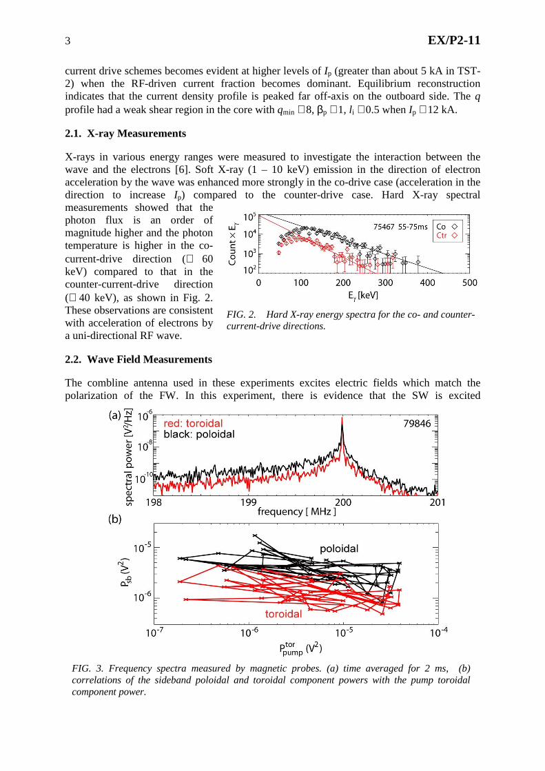
X-rays in various energy ranges were measured to investigate the interaction between the wave and the electrons [6]. Soft X-ray (1 – 10 keV) emission in the direction of electron acceleration by the wave was enhanced more strongly in the co-drive case (acceleration in the direction to increase Ip) compared to the counter-drive case. Hard X-ray spectral measurements showed that the photon flux is an order of magnitude higher and the photon temperature is higher in the co-current-drive direction (≅ 60 keV) compared to that in the counter-current-drive direction (≅ 40 keV), as shown in Fig. 2. These observations are consistent with acceleration of electrons by a uni-directional RF wave.
2.2. Wave Field Measurements
The combline antenna used in these experiments excites electric fields which match the polarization of the FW. In this experiment, there is evidence that the SW is excited
FIG. 2. Hard X-ray energy spectra for the co- and counter-current-drive directions.
FIG. 3. Frequency spectra measured by magnetic probes. (a) time averaged for 2 ms, (b) correlations of the sideband poloidal and toroidal component powers with the pump toroidal component power.

4 EX/P2-11
nonlinearly. Two orthogonal single-turn loops, each enclosed in a stainless steel cover with a slit aligned perpendicularly to the plane of the loop (same construction as the probe in the array shown in Fig. 6), were used to measure the frequency spectra of the toroidal component (FW polarization) and the poloidal component (SW polarization) of the RF magnetic field in the plasma edge region, as shown in Fig. 3(a). While the pump wave at 200 MHz (frequency integral over ± 1 kHz) has a stronger toroidal component (0.135 mW vs. 0.023 mW), the lower sideband (195 < f < 201 MHz excluding the pump wave) has a stronger poloidal component (0.035 mW vs. 0.109 mW), suggesting generation of the SW by parametric decay. The time evolution indicates the tendency of the pump wave toroidal component to weaken when the sideband poloidal and toroidal components intensify, as can be seen from the negative correlations in Fig. 3(b).
3. Plasma Start-up Experiment Using the Grill Antenna
It is expected that the effectiveness of current drive would improve if the antenna could excite the LH wave directly. Two types of traveling-wave LH antennas will be tested on TST-2. With the installation of ECW power at 8.2 GHz with output power of up to 15 kW, the operating regime for Ip ramp-up experiments can be extended to higher toroidal fields (Bt0 ≤ 0.3 T), where accessibility of the LH wave is improved [4]. The first type of LH antenna is a dielectric-loaded waveguide array (or “grill”) antenna (Fig. 4 left). Each waveguide is a rectangular alumina block with the surfaces covered by a layer of 80 µm thick nickel, deposited by electroless plating. The waveguides have cross sectional dimensions of 30 mm (width) × 285 mm (height). The two middle waveguides are 1332 mm long while the two outer waveguides are 911 mm long to accommodate RF power feeders. The RF power is fed from the side of the waveguide through a coax-waveguide transition (Fig. 4 right). The vacuum seal is accomplished by O-rings around each waveguide. The open end of the
FIG. 4. Dielectric-loaded waveguide array (grill) antenna for LH wave excitation.

5 EX/P2-11
waveguides do not have poloidal or toroidal curvature, but the “picture-frame” protective limiter is contoured to match a typical plasma surface. This antenna is now installed on TST-2, and initial experiments have begun.
3.1. Comparison of Plasma Start-up with Grill Antenna and Combline Antenna
Plasma start-up data obtained using the grill antenna are shown in Fig. 5, compared with data obtained using the combline antenna. For similar RF power and vertical field, the observed driven current is similar but slightly lower. This may be attributed to a lower directivity of the waves excited by the grill antenna under the present condition. The reflectivity is observed to alternate between high (nearly 100%) and low (nearly 0%) in adjacent waveguides, resulting in a nearly symmetric spectrum of the wavenumber parallel to the magnetic field, k||.
3.2. Wave Polarization and Wavenumber Measurements
An array of five magnetic probes (same type as described in Sec. 2.2) arranged in a cross configuration (Fig. 6) was installed to measure the wavenumber of the waves excited in the plasma. The whole assembly can be rotated about its axis to measure the toroidal (horizontal) and poloidal (vertical) components of the wavevector (kt and kp) for either or depending on the probe orientation (θ = 0° and 90°, respectively). Phase differences of probes a, b, c, d relative to probe e are measured to calculate the toroidal and poloidal components of
FIG. 6. Magnetic probe array. The entire assembly can be rotated about its axis to measure
(when θ = 0°), (when θ = 90°), or their linear combination.
FIG. 5. Comparison of plasma current driven by waves excited by the waveguide (grill) antenna and by the combline antenna. Dependence on the vertical field (left) and RF power (right).
6 EX/P2-11
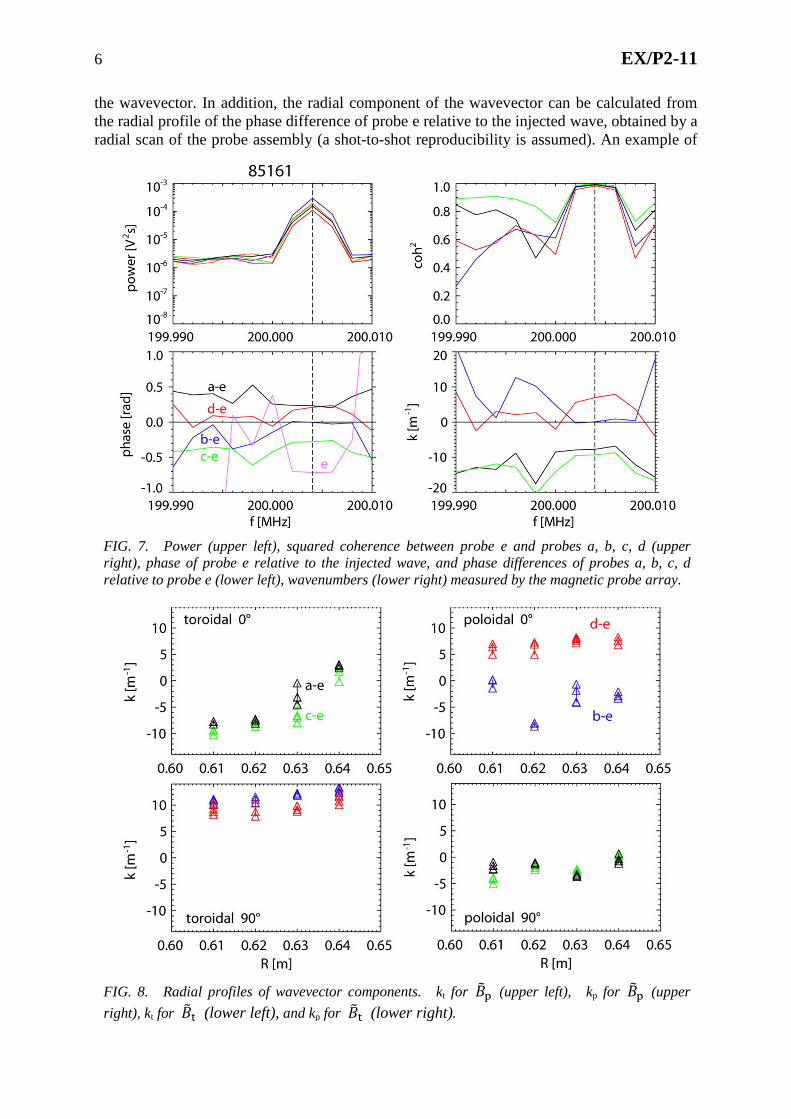
the wavevector. In addition, the radial component of the wavevector can be calculated from the radial profile of the phase difference of probe e relative to the injected wave, obtained by a radial scan of the probe assembly (a shot-to-shot reproducibility is assumed). An example of
FIG. 8. Radial profiles of wavevector components. kt for (upper left), kp for (upper
right), kt for (lower left), and kp for (lower right).
FIG. 7. Power (upper left), squared coherence between probe e and probes a, b, c, d (upper right), phase of probe e relative to the injected wave, and phase differences of probes a, b, c, d relative to probe e (lower left), wavenumbers (lower right) measured by the magnetic probe array.

7 EX/P2-11
data obtained in low current (Ip ~ 1 kA) plasmas initiated and maintained by waves excited by the grill antenna is shown in Fig. 7. In these plasmas, the magnetic field line pitch angle is very small (less than 1°) so k|| is nearly the same as kt. In the following discussion, wavevector components are evaluated at the pump wave frequency (200.004 MHz).
The radial profiles of kt and kp for (SW component) and (FW component) are shown in Fig. 8. The radial profiles of the phase measured by probe e (relative to the injected wave) for the two polarizations are shown in Fig. 9, from which the radial component of the wavevector kR can be obtained (assuming a shot-to-shot reproducibility). The result is summarized in Table I. These can be compared with kt ~ 50 m−1 and kp ~ 10 m−1 which the grill antenna is trying to excite (for a phase difference of 90° between adjacent waveguides used in this experiment). The measured magnitude of the parallel wavenumber |k||| for both SW and FW polarizations are substantially smaller than that excited by the antenna. This observation may indicate absorption of the higher |k||| components by the plasma. The magnitude of the perpendicular wavenumber |k⊥| is larger for the SW than the FW, consistent with the dispersion relation for these waves.
TABLE I: Wavevector components for (SW component) and (FW component).
(SW component) (FW component)
|kt| ≅ |k||| < 10 m−1 ~ 10 m−1
|kp| < 10 m−1 < 5 m−1
|kR| ~ 35 m−1 ~ 10 m−1
|k⊥| ~ 35 m−1 ~ 10 m−1
4. New Traveling Wave LH Antenna
The second type of LH antenna is an array of mutually coupled bars oriented in the vertical direction, similar to the combline antenna, but with the electric field in the horizontal direction rather than the vertical direction. It therefore couples predominantly to the SW rather than the FW. Thirteen mutually coupled elements comprise the antenna array. For exciting a traveling wave, RF power is fed to one outermost element (“input element”). Intermediate elements are excited by mutual capacitance from neighboring elements, and the power that is not radiated to the plasma exits from the other end of the array (“output element”). The array behaves like a band-pass filter, and the phase shift between elements is determined by choosing the operating frequency within the pass-band. The feeders must attach to the input and output elements at appropriate points where the input impedance is 50 Ω. This antenna is presently being tested at low power for final adjustment.
FIG. 9. Radial profiles of phase measured by probe e relative to the injected wave.

8 EX/P2-11
5. Conclusions
ST plasma initiation and Ip ramp-up by waves in LH frequency range were demonstrated for the first time on TST-2 using a combline antenna (FW excitation) and a dielectric-loaded waveguide array (grill) antenna (SW excitation). Whereas initial formation of the ST plasma is independent of frequency or polarization, further Ip ramp-up to ~ 10 kA was most efficient with uni-directional traveling waves in the LH frequency range. Ip ramp-up to 15 kA has been achieved with 60 kW of net RF power using the combline antenna. X-ray measurements indicate acceleration of electrons by a uni-directional RF wave. The combline antenna excites the FW, but polarization-resolved wave field measurements indicate a nonlinear generation of the SW by parametric decay. A similar but slightly lower efficiency of Ip ramp-up obtained during initial operation of the grill antenna may be the result of poor directivity of the excited LH wave. Results of polarization and wavevector measurements of the wave magnetic field were qualitatively consistent with expectations based on dispersion relations for the FW and the SW. A second type of LH antenna, an array of capacitively coupled elements, is being tested at low power for final adjustment. This antenna is capable of exciting the SW with much higher directivity than the grill antenna.
Acknowledgments
This work is supported by Japan Society for the Promotion of Science Grants-in-Aid for Scientific Research (S) (21226021), (A) (21246137), and (B) (23360409), by NIFS Collaboration Research Program NIFS12KNWR001, and by Japan/US Cooperation in Fusion Research and Development. Work at General Atomics is supported by US DoE contract DE-AC03-97ER-54411.
References
[1] NISHIO, S., et al., “Technological and Environmental Prospects of Low Aspect Ratio Tokamak Reactor VECTOR,” in Fusion Energy 2004 (Proc. 20th Int. Conf., Vilamoura, 2004) (Vienna: IAEA), CD-ROM file FT/P7-35 and http://www-naweb.iaea.org/napc/ physics/fec/fec2004/datasets/index.html.
[2] TOBITA, K., et al., “SlimCS - compact low aspect ratio DEMO reactor with reduced-size central solenoid,” Nucl. Fusion 47 (2007) 892.
[3] TAKASE, Y., et al., “Initial results from the TST-2 spherical tokamak,” Nucl. Fusion 41 (2001) 1543.
[4] TAKASE, Y., et al., “Development of a plasma current ramp-up technique for spherical tokamaks by the lower hybrid wave,” Nucl. Fusion 51 (2011) 063017.
[5] OGAWA, T., et al., “Radiofrequency experiments in JFT-2M: Demonstration of innovative applications of a travelling wave antenna,” Nucl. Fusion 41 (2001) 1767.
[6] WAKATSUKI, T., et al., “X-ray Measurements during Plasma Current Start-up Experiments using the Lower Hybrid Wave on the TST-2 Spherical Tokamak,” IEEJ Trans. FM 132 (2012) 485.


![Changes in plasma lipidome following initiation of ... · increased risk for cardiovascular disease (CVD) [1]. HIV and ARV-associated dyslipidaemia is responsible for a component](https://static.fdocuments.in/doc/165x107/5ed81bfad9463e16115a2507/changes-in-plasma-lipidome-following-initiation-of-increased-risk-for-cardiovascular.jpg)