Non-contact multi-sensor 3D metrology system
8
Non-contact multi-sensor 3D metrology system
Transcript of Non-contact multi-sensor 3D metrology system

Non-contact multi-sensor 3D metrology system

1
The HN-6060 non-contact, multi-sensor, 3D metrology system makes automatic shape measurement of complex components a reality. With a two-axis rotary table and a three-axis high-rigidity air bearing construction CMM, incorporating five-axis synchronous linear motor drive and control mechanism, the hardware has been optimized for stability. Additionally, with the adoption of Nikon’s proprietary low thermal expansion encoder scales and a design optimized for minimizing Abbé errors, the accuracy of the this high-precision 3D measurement instrument is 1.5+4L/1000 μm.
The HN-6060 is equipped with newly developed high-speed and high-precision laser scanner and SFF (shape from focus) sensor, which uses active texture projection to perform high-precision measurement of shapes even with glossy surfaces or with no surface texture. Touch probes and optical heads with built-in TTL laser AF (with proven performance in Nikon’s NEXIV VMR series CNC Video Measuring System) complete the multi-sensor system. The system’s use of multi-sensors allows it to perform diverse shape measurements of parts such as complex automotive and machined components, molded parts, medical devices etc.
HN-6060
Non-Contact Multi-Sensor 3D Metrology
Nikon 3D metrology system — from critical dimension measurement to high- precision, non-contact shape inspectionThe HN-6060 — Nikon’s next-generation, non-contact, 3D metrology system is equipped with the latest multi-sensing metrology technologies, including a newly developed high-precision laser scanner that combines optical and image processing technologies. As a new generation metrology system, the HN-6060 assists the manufacturing process and assures product quality.

2
A high level of user operability is incorporated, including fixed viewpoint five-axis operation control (for easy acquisition of surface point clouds) plus simulation running mode.With a design that takes full account of user safety and operability (such as fixed viewpoint joystick operation for easy acquisition of point clouds from 3D shapes and simulation for collision avoidance), the system makes non-contact shape inspection a reality.
HN Metrology 3D — feature-rich 3D metrology softwareThe new HN Metrology 3D software represents an evolution in multi-sensor metrology software based on the dimension inspection software for the proven Nikon NEXIV VMR series. The user can easily make use of a wide variety of advanced functions for set-up, teaching, shape measurement, comparative error estimation with reference to 3D CAD data, and result output.
Focus point cloud analysis software (optional)The Focus Inspection option allows error comparison with reference to 3D CAD data and creation of detailed reports based on high-precision point cloud and mesh data. Point clouds can also be used for reverse engineering.
The main features of the HN-6060High-precision and optimized shape capturing and measurement for 3D componentsNikon has combined leading-edge optical and hardware control technology and developed a laser scanner system that acquires point clouds with high precision at a rate of 120,000 points per second. The HN-6060 has proven its ability in comparison checking of surface shape inspection data with 3D CAD models (part-to-CAD comparison) and in reverse engineering.
Enhanced multi-sensor technology enables shape inspection without manual preparation of samplesUsing newly developed high-precision laser scanner, SFF and tactile sensors, and five axis hardware control, the system can perform many types of high-precision inspection of components and match processing for automatic assembly of point clouds. The system also allows high-precision, non-contact 3D inspection without manual preparation (such as application of powder to the object under inspection) of black molded components and shapes with glossy surfaces, which have traditionally been difficult to measure.
Five-axis synchronized hardware control for high-precision metrologyIn addition to a newly developed high-precision three-axis orthogonal drive system driven by linear motors, the system is also equipped with a two-axis rotary table. This technology allows for acquisition and inspection of point clouds at the optimum orientation necessary for gear inspection.
Home appliances: 3D external casing and internal functional parts
Pressed Parts: 3D surface form part to CAD inspection with GD&T evaluations
Turbine blade: part to CAD inspection with cross section analysis
The HN-6060 metrology system assists, drives and streamlines the production process with high accuracy 3D digitizing and measuring capabilities. The unique system is designed in close cooperation with leading industrial manufacturers and offers many benefits to produce better products in a faster way.
Gear Metrology: Automotive hypoid/spiral bevel gear teeth surface
Full 3D point cloud data of complex partsNon-contact measurementManual preparation-free laser scanningHigh precision and high qualityFast, automated inspectionEasy operationHigh rigidity 5 axis hardwareMulti-sensors cover a wide application range

3
The five-axis hardware control, which incorporates Nikon control technology, supports multi-sensor high-precision non-contact 3D metrology.
High-precision, two-axis rotary stageThe adoption of a high-rigidity design enables control with high-precision positioning repeatability and unlimited angular rotation with a free swivel angle of up to 95°. Ideal for gear inspection, the system carries out inspection with the optimum sensor orientation for the stereoscopic shape of the target object.
CMM design for top accuracyA linear motor drive mechanism is the heart of the three-axis orthogonal section, guaranteeing stable and high-precision inspection over a long period of time. Concurrently, the system also achieves high-precision positioning control. With the system’s high-rigidity air bearing construction, the design has been optimized to compensate deformation caused by changes in temperature. Additionally, with the adoption of Nikon’s proprietary low-temperature expansion encoder scales and a layout optimized to minimize Abbé errors, the accuracy of the high-precision 3D measurement hardware is 1.5+4L/1000 μm.
Ergonomic operator consoleThe console, which enables easy five-axis synchronized operation, features a simple configuration and includes switches for changing between sensors, and buttons for carrying out simple inspection. The fixed-viewpoint control function allows for easy control of the optimum sensor attitude for a particular shape.
Calibration system for multi-sensor metrologyThe system comes with a calibration set that is designed to enable non-contact, 3D metrology at the highest accuracy. This enables measurement with a single datum using a variety of different sensors. A specially made ball bar, traceable to the National Institute of Advanced Industrial Science and Technology’s non-contact measurement standards is used for calibration of the main unit. This guarantees traceability to public and international agencies that require certified non-contact measurements of the highest precision.
Light sectioning sensor calibration
Five-axis precision calibration using a multi-datum ball
Touch-probe calibration
Non-contact measurement precision verification using a ball bar
The low thermal expansion linear encoder scales, which are key components in high-precision measurement, are manufactured in-house, using Nikon optical technology.

4
50mm
Light emitter
FinderCamera
Light detector
Light emitter
FinderCamera
Light detector
Level-differencedetection range: 20 mm
Multi-sensor measurement head featuring Nikon's newly developed high-precision laser scanner that attains non-contact measurement uncertainty of 5 μm (Es, MPE).
High-speed high-density acquisition of shape point cloud dataHigh-speed digital transform processing enables surface point clouds to be acquired at the rate of 120,000 points per second. Fine Mode enables high-density acquisition of in-line point clouds with a line pitch of 20 μm — not only for shapes with features but also for surface waviness.
Image-processing optical system with built-in SFF sensor and TTL laser AF, and 15x zoomThe system features the proven high-NA zoom optical system from the NEXIV VMR series CNC Video Measuring Systems — now illuminated exclusively with LEDs — as well as image processing developed in-house by Nikon. In addition, the system is equipped with the very latest SFF (shape from focus) inspection sensor. Using active texture pattern projection mechanism, the system can perform high-precision shape acquisition for surfaces that are as devoid of texture as the surface of a mirror, while TTL laser AF enables level difference and profile measurement.
Ready to fit with Renishaw touch probesIn cases where touch probes are required for datum shape acquisition (for example, with cylindrical shapes), measurement with the TP200 trigger sensors, as fitted to the PH1, is effective.
Newly developed high-precision laser scannerAs a long-established manufacturer of high-quality optical instruments, Nikon took a completely fresh look at non-contact-sensor optical systems. In order to achieve measurement with such an unprecedentedly high degree of precision, Nikon developed special optics such as a newly designed cylindrical lens for the light emitter and an image-side telecentric optical system directing the object image to a detector with high precision. Nikon, also, designed the hardware mechanism suppressing variation in magnification due to changes in temperature. In addition, the implementation of a hinged optical system (in accordance with the Scheimpflug principle) enables surface data to be acquired with a constant focus above the detection device. A CCD with dramatically improved smear resistance has been employed for the light detecting section. In tandem with the bright optical system, this enables detection on low-reflectivity, or glossy surfaces without manual preparation such as spraying. The system has a built-in finder-camera for monitoring the surface measurement of an object. This enables the user to carry out measurement programming in the video window of the host PC and to monitor inspection in real time.
High-resolution small 3D surface metrology by SFF sensor
Edge detection by image processing
5
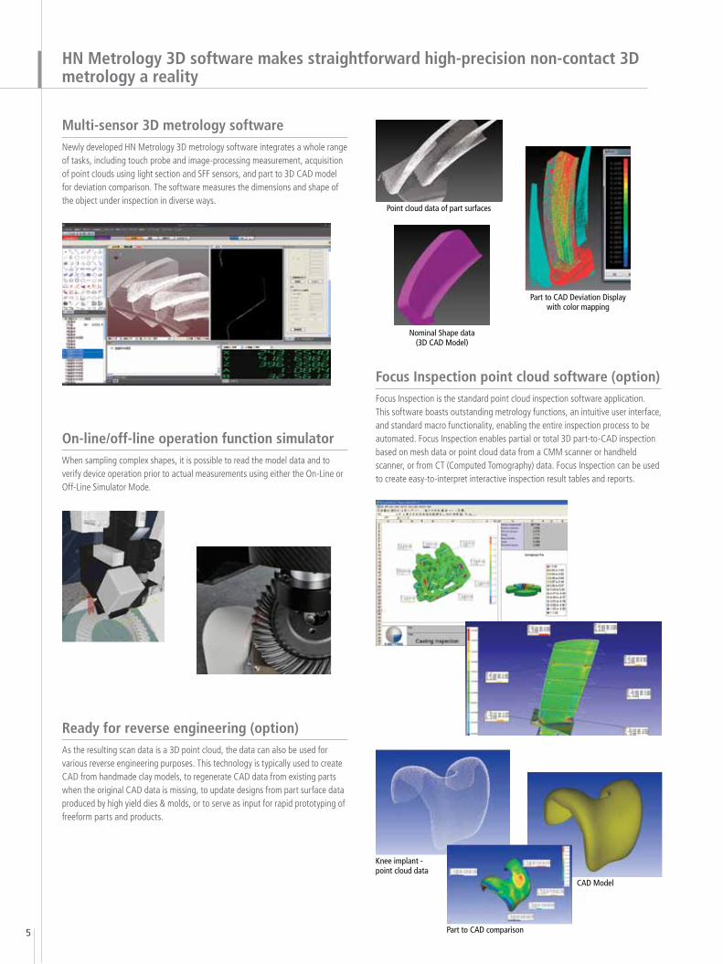
HN Metrology 3D software makes straightforward high-precision non-contact 3D metrology a reality
Multi-sensor 3D metrology software Newly developed HN Metrology 3D metrology software integrates a whole range of tasks, including touch probe and image-processing measurement, acquisition of point clouds using light section and SFF sensors, and part to 3D CAD model for deviation comparison. The software measures the dimensions and shape of the object under inspection in diverse ways.
On-line/off-line operation function simulatorWhen sampling complex shapes, it is possible to read the model data and to verify device operation prior to actual measurements using either the On-Line or Off-Line Simulator Mode.
Nominal Shape data (3D CAD Model)
CAD Model
Part to CAD comparison
Knee implant - point cloud data
Focus Inspection point cloud software (option)Focus Inspection is the standard point cloud inspection software application. This software boasts outstanding metrology functions, an intuitive user interface, and standard macro functionality, enabling the entire inspection process to be automated. Focus Inspection enables partial or total 3D part-to-CAD inspection based on mesh data or point cloud data from a CMM scanner or handheld scanner, or from CT (Computed Tomography) data. Focus Inspection can be used to create easy-to-interpret interactive inspection result tables and reports.
Ready for reverse engineering (option)As the resulting scan data is a 3D point cloud, the data can also be used for various reverse engineering purposes. This technology is typically used to create CAD from handmade clay models, to regenerate CAD data from existing parts when the original CAD data is missing, to update designs from part surface data produced by high yield dies & molds, or to serve as input for rapid prototyping of freeform parts and products.
Point cloud data of part surfaces
Part to CAD Deviation Display with color mapping
6
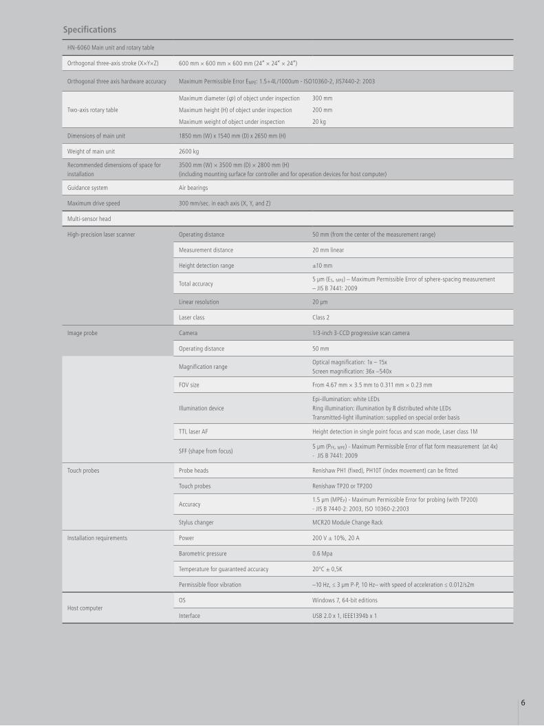
Specifications
HN-6060 Main unit and rotary table
Orthogonal three-axis stroke (X×Y×Z) 600 mm × 600 mm × 600 mm (24” × 24” × 24”)
Orthogonal three axis hardware accuracy Maximum Permissible Error EMPE: 1.5+4L/1000um - ISO10360-2, JIS7440-2: 2003
Two-axis rotary table
Maximum diameter (φ) of object under inspection
Maximum height (H) of object under inspection
Maximum weight of object under inspection
300 mm
200 mm
20 kg
Dimensions of main unit 1850 mm (W) x 1540 mm (D) x 2650 mm (H)
Weight of main unit 2600 kg
Recommended dimensions of space for installation
3500 mm (W) × 3500 mm (D) × 2800 mm (H)(including mounting surface for controller and for operation devices for host computer)
Guidance system Air bearings
Maximum drive speed 300 mm/sec. in each axis (X, Y, and Z)
Multi-sensor head
High-precision laser scanner Operating distance 50 mm (from the center of the measurement range)
Measurement distance 20 mm linear
Height detection range ±10 mm
Total accuracy 5 μm (ES, MPE) – Maximum Permissible Error of sphere-spacing measurement – JIS B 7441: 2009
Linear resolution 20 μm
Laser class Class 2
Image probe Camera 1/3-inch 3-CCD progressive scan camera
Operating distance 50 mm
Magnification rangeOptical magnification: 1x – 15xScreen magnification: 36x –540x
FOV size From 4.67 mm × 3.5 mm to 0.311 mm × 0.23 mm
Illumination deviceEpi-illumination: white LEDsRing illumination: illumination by 8 distributed white LEDsTransmitted-light illumination: supplied on special order basis
TTL laser AF Height detection in single point focus and scan mode, Laser class 1M
SFF (shape from focus)5 μm (PFF, MPE) - Maximum Permissible Error of flat form measurement (at 4x) - JIS B 7441: 2009
Touch probes Probe heads Renishaw PH1 (fixed), PH10T (index movement) can be fitted
Touch probes Renishaw TP20 or TP200
Accuracy1.5 μm (MPEP) - Maximum Permissible Error for probing (with TP200) - JIS B 7440-2: 2003, ISO 10360-2:2003
Stylus changer MCR20 Module Change Rack
Installation requirements Power 200 V ± 10%, 20 A
Barometric pressure 0.6 Mpa
Temperature for guaranteed accuracy 20ºC ± 0,5K
Permissible floor vibration –10 Hz, ≤ 3 μm P-P, 10 Hz– with speed of acceleration ≤ 0.012/s2m
Host computer OS Windows 7, 64-bit editions
Interface USB 2.0 x 1, IEEE1394b x 1

This brochure is printed on recycled paper made from 40% used material.
Specifications and equipment are subject to change without any notice or obligationon the part of the manufacturer. October 2010 ©2005-10 NIKON CORPORATION
Printed in Japan (1010-00)T Code No. 2CE-IFEH-1
N.B. Export of the products* in this catalog is controlled under the Japanese Foreign Exchange and Foreign Trade Law. Appropriate export procedure shall be required in case of export from Japan.* Products: Hardware and its technical information (including software)• Monitor images are simulated.• Company names and product names appearing in this brochure are their registered trademarks or trademarks.
WARNINGTO ENSURE CORRECT USAGE, READ THE CORRESPONDING MANUALS CAREFULLY BEFORE USING YOUR EQUIPMENT.
NIKON METROLOGY, INC.12701 Grand River Avenue, Brighton, MI 48116 U.S.A.phone: +1-810-220-4360 fax: +1-810-220-4300E-mail: [email protected]://us.nikonmetrology.com/http://www.nikoninstruments.com/
NIKON METROLOGY EUROPE NVGeldenaaksebaan 329, 3001 Leuven, Belgiumphone: +32-16-74-01-00 fax: +32-16-74-01-03E-mail: [email protected]://www.nikonmetrology.com/
NIKON INSTRUMENTS (SHANGHAI) CO., LTD.CHINA phone: +86-21-6841-2050 fax: +86-21-6841-2060(Beijing branch) phone: +86-10-5831-2028 fax: +86-10-5831-2026(Guangzhou branch) phone: +86-20-3882-0552 fax: +86-20-3882-0580
NIKON SINGAPORE PTE LTDSINGAPORE phone: +65-6559-3618 fax: +65-6559-3668
NIKON MALAYSIA SDN BHDMALAYSIA phone: +60-3-7809-3688 fax: +60-3-7809-3633
NIKON INSTRUMENTS KOREA CO., LTD.KOREA phone: +82-2-2186-8400 fax: +82-2-555-4415
NIKON INDIA PRIVATE LIMITEDINDIA phone: +91-124-4688500 fax: +91-124-4688527
NIKON CANADA INC.CANADA phone: +1-905-602-9676 fax: +1-905-602-9953
NIKON INSTRUMENTS S.p.A.ITALY phone: +39-055-300-96-01 fax: +39-055-30-09-93
NIKON AGSWITZERLAND phone: +41-43-277-28-67 fax: +41-43-277-28-61
NIKON GMBH AUSTRIA AUSTRIA phone: +43-1-972-6111-00 fax: +43-1-972-6111-40
NIKON BELUXBELGIUM phone: +32-2-705-56-65 fax: +32-2-726-66-45
NIKON METROLOGY UK LTD.UNITED KINGDOM phone: +44-1332-811-349 fax: +44-1332-639-881E-mail: [email protected]
NIKON METROLOGY SARLFRANCE phone: +33-1-60-86-09-76 fax: +33-1-60-86-57-35E-mail: [email protected]
NIKON METROLOGY GMBHGERMANY phone: +49-6023-91733-0 fax: +49-6023-91733-19E-mail: [email protected]
NIKON CORPORATIONShin-Yurakucho Bldg., 12-1, Yurakucho 1-chome, Chiyoda-ku, Tokyo 100-8331, Japanphone:+81-3-3216-2384 fax:+81-3-3216-2388 http://www.nikon.com/instruments/
Top surfaceDimensions
1850 530
780
850
2650
1780
840
550
470
890
Cente
r of g
ravity
(154
0)
Cent
er o
f gra
vity
770
1400
1540
805Center of gravity
800580
625 (=P125 X 5) 250
1000 (=P125 X 8)
486.5
116.5
1400
705 M8 DEPTH 28
8 X M8 DEPTH 10
240
150
45°8 X M8 THRU
HN
6060
_EN
_041
1 –
Cop
yrig
ht N
ikon
Met
rolo
gy N
V 2
011.
All
right
s re
serv
ed. A
ll sp
ecifi
catio
ns a
re s
ubje
ct t
o ch
ange
with
out
notif
icat
ion.
The
mat
eria
ls p
rese
nted
her
e ar
e su
mm
ary
in n
atur
e an
d in
tend
ed f
or g
ener
al in
form
atio
n on
ly.