NO TAT 7 NR*/ 8 · NO TAT 7 NR*/ 8 UNDERGROUND AMMUNITION STORAGE Report I Test Programme,...
69
*~*^.A~ ML ;V r, l! I USADAC TECHNICAL LIBRARY 5 0712 0102 373 77} rCRTIFIKATÜRISK i NO TAT NR*/ 78 UNDERGROUND AMMUNITION STORAGE Report I Test Programme, Instrumentation, and Data Reduction BEST AVAILABLE COPY St. > o / «7 7 b DISTRmUTIC^STÄTmENT_Ä_ Approved foi public release; Distribution Unlimited CRSVARETS BYGMNCST JENESTE
Transcript of NO TAT 7 NR*/ 8 · NO TAT 7 NR*/ 8 UNDERGROUND AMMUNITION STORAGE Report I Test Programme,...

*~*^.A~ ML
;V r, l! I
USADAC TECHNICAL LIBRARY
5 0712 0102 373
77}
rCRTIFIKATÜRISK
i
NO TAT NR*/78
UNDERGROUND AMMUNITION STORAGE
Report I
Test Programme, Instrumentation, and Data Reduction
BEST AVAILABLE COPY
St. > o / «7 7 b
DISTRmUTIC^STÄTmENT_Ä_
Approved foi public release; Distribution Unlimited
CRSVARETS BYGMNCST JENESTE

NORWEGIAN DEFENCE CONSTRUCTION SERVICE Office of Test and Development
Fortifilcatorisk notat nr 80/72
UNDERGROUND AMMUNITION STORAGE
; Report I
1 Test Programme, Instrumentation, and Data Reduction
by
A. Skjeltorp, T. Hegdahl, and A. -Jenssen
DISTRIBUTION STATEMENT^ Approved foi public release;
Distribution Unlimited
September 1975

TABLE OP CONTENTS
... Page
ABSTRACT . 1
1. INTRODUCTION 2
1.1 Study Objectives ., 2
1.2 Problem Background 2
1.3 Scope of Report . 3
2:. THEORETICAL CONSIDERATIONS ' 4
2.1 Scaling Relationships 4
2-,2 Effects of Thermal Interactions with the Walls 6
2.3 Mechanical Interactions with the Walls 8
2.4 Viscous Losses to the Walls 11
2.5 Validity of Model and Large Scale Testing 13
3. TEST PROGRAMME AND MODELS .15
3.1 Report II .15
3.2 Report III ' 15
3.3 Report IV 15
3.4 Report V 16
3.5- Model Construction 16
4. INS TRUMEN TATION 17
4.1 Pressure Transducers and Measuring Chain 17
4.2 Transducer Calibration and System Linearity 18
5. DATA REDUCTION 18
5.1 Curve Tracing and A/D Conversion 18
5.2 Pitting Technique for Scaling Relationships 18
5.3 Electrical Filter for Chamber Pressure 19
REFERENCES 20-23
APPENDIX A DEFINITIONS OP SYMBOLS
DEFINITION OF TERMS USED IN UNDER- GROUND AMMUNITION STORAGE
APPENDIX B CALIBRATION OF PRESSURE TRANSDUCERS AND MEASURING CHAIN
APPENDIX C CURVE TRACING AND A/D CONVERSION

APPENDIX D FITTING TECHNIQUE TO ESTABLISH SCALING RELATIONSHIPS
APPENDIX E ELECTRICAL FILTER FOR CHAMBER PRESSURE
Tables
Figures
ABSTRACT
This report is the first in a series of five describing an
extensive series of model tests on air blast propagation
in underground ammunition storage sites. A general descrip-
tion is given of the scope and purpose of the tests as well
as a presentation of the principles of scaling and various
intrinsic uncertainties which may cause problems in the
modelling technique. The report also surveys the test
programme, instrumentation, and data reduction for the whole
test series.

1. INTRODUCTION
This report is the first in a series of five /1-6/*
describing an extenive series of model tests on air
blast propagation in underground ammunition storage
sites.
These tests are a natural continuation of earlier
'; work performed by this office in this general field
/7-12/.
1 •1 Study Ob jecti ves
The basic objectives for performing these tests have
been to use several empirical and theoretical scaling
techniques to combine'air blast data into a form
that allows the prediction of blast wave propagation
inside a wide range of typical underground ammunition
storage sites as a function of explosive quantities
and geometrical parameters. These methods of pre-
dictions will thus give the design engineer a tool
to evaluate the effects of different layouts and
geometries. In particular, it will be possible to
specify the necessary strength of blast doors, blast
valves and blast walls to prevent the propagation of
detonation from one chamber to another in a connected
chamber storage site. Furthermore, in the determina-
tion of the pressure and impulse at the exit of the
tunnel leading into the underground storage complex,
it will be possible to determine the hazardous area
around such a site /13, 14/.
"I • ^ Pr obi em Background
The detailed analysis of accidental explosions in
underground ammunition storage sites in regard to
blast wave propagation generally involves three
distinct steps:
Determination of the pressure-time history in the
storage chamber; determination of the blast wave
propagation fron the storage chamber down the main
passageway (or between chambers in connected chamber
* Numerals in / / designate appended references

storage sites); and finally, mapping of the blast
wave emerging from the exit of the tunnel in the
terrain outside. This analysis can generally be
performed in three ways: full scale testing; theoreti-
cal calculations; or finally, model testing.
As far as theoretical treatment is concerned, one
can in principle describe the blast propagation by
sets of mathematical equations, and attempt to solve
these equations numerically. However, the methods of
computation are often so involved that one cannot
economically repeat these computations while varying in
a systematic manner all of the physical parameters
which may affect the blast wave. One important point
to remember is that one has no idea of the accuracy
of such theoretical solutions until proof tested.
The second possibility is experimental studies in
large or full scale. Such tests would, however, be
very costly, take long time and also cause instru-
mentation and manning problems. This would limit
the number of tests to a very few special cases, and
there could be a tendency to draw conclusions outside
the range of the actual experimental and geometrical
conditions.
The third and last possibility is model testing
using similarity methods. This method forms the basis
for the experiments presented in the present reports.
"1 • 5 Scope of Report
The general principles of scaling are presented in
Sec.2 together with a discussion of various intrinsic
uncertainties which may cause problems in the modelling
technique. The test plan and models are described
in Sec.3 followed by a presentation of the instrumenta-
tion in Sec.4. Section 5 contains a description of
the data reduction and a discussion of the experi-
mental errors.

The appendi.ces preside more detailed sources of in-
formation of the data reduction and analysis for
this whole series of reports.
Because several terms that relate to "blast propaga-
tion in underground ammunition storage are used
differently by different authors, a list of defini-
tions is also included as a separate appendix.
2. ■ THEORETICAL CONSIDERATIONS
2•1 Scaling Relationships
The basis for the scaling relationships used in the ■ present work correspond to the familiar Hopkinson
scaling laws /15/. The use of models requires com-
plete geometrical similarity between the model and the
full scale system. If the linear scale factor is n,
the relationship between distances in the full scale
(subcript F) and model (subscript M) is
Lp - nlty (2.1 a)
Likewise, areas scale as
AF = n2^, (2.1 b)
and volumes as
Vp = n3VM (2.1 c)
For the energy release
Ep = n3Ew (2.1 d)
This energy scaling is also valid for the explo-
sive quantity if the energy release per unit weight
is constant:
Qp = n3QM (2.1 e)

5
The "blast wave parameters scale as
Pp - PM (2-1 f)
for peak pressure, and
Ip = nIM . (2.1 g)
for impulse, and
tp = ntM (2.1 h)
for characteristic times.
Inherent in this simple scaling is the assumption
of perfect gas "behaviour of air and no differences
in ambient conditions (e.g. temperature and pressure)
between the model and prototype. Furthermore, the
theory does not account for energ3>" dissipating effects
due to tunnel or chamber walls such as: thermal energy
transmission to the walls; elastic or inelastic de-
formation of the walls; viscous loss due to wall rough-
ness.
If one tried to scale all these effects properly from
a full scale system, it would require tests in scale
1:1. It is therefore important to try to put an upper
limit on the uncertainties involved in neglecting
non-scaled effects. This will be attempted in Sec.2.2 -
2.4, and it will be shown that tlae effects from these
sources will he relatively unimportant except maybe
for the viscous loss due to wall roughness. However,
as the relative wall roughness is normally significantly
larger in a full.scale site than in a steel model, the
model data would tend to be conservative or on the safe
side.
As will be discussed in the succeeding reports, care-
ful inspection of the experimental results from the
various model tests have produced extended empirical
scaling re1ationships representing a wide range of
important geometrical parameters. One should note

the distinction between scaling laws and scaling
relationships in this connection as the former re-
quire complete geometrical similarity.between the
model and the prototype.
2•2 Effects of Thermal Interactions with the Walls
The detonation of explosives in confined regions such
as storage chambers produces hot gases from which
energy is transferred by heat flow to the much cooler
confining walls. There are two mechanisms involved
in this heat transfer: Radiation and a combination
of 'Conduction and convection. In that the surrounding
medium is rock in the full scale case and steel in the
present model tests,the heat losses do not scale due
to the large difference in thermal properties«,
The question is therefore whether these effects will
be of such magnitude that it will introduce large
systematic errors in the scaled data.
Earlier theoretical calculations have been carried out
to estimate the heat conduction in a detonation
chamber in full scale (rock) and steel models in
linear scales 1:10 and 1:100 /'16/. The basic results
are reproduced in Fig.2.2 for a loading density of
100 kg TNT/m3. It can be seen that for the full
scale case (chamber radius R = 6m), the heat loss
is relatively unimportant. For a steel model in a
linear scale 1:100, the heat loss is estimated to be
about 14/o of the total heat at a scaled time t/R_ =
20 ms/rn, corresponding to 120 ms in the full scale
case /17/. Qualitative arguments have also been
given to the effect that the relative heat loss in-
creases with decreasing loading densities and that
the result from a 1:100 steel model at low loading
densities are expected to be quite misleading unless
a heat loss correction is applied. Fortunately, the
present series of experiments offers some results
which can be used to check these conclusions. How-
ever, first an attempt will be made to convert the
thermal loss into pressure effects. This cannot be

7
performed in a straightforward way, but to first
order the pressure decrease in an unvented chamber
due to conduction loss can be roughly described as
/18/
§E=^°U-D/V. (2.2 a)
Here, dE /dt is the heat loss in watts, V is
the chamber volume, and y = c /c the usual
specific heat ratio for the detonation products.
Assuming 'V to be constant, the relative pressure
decrease can be found from Eq. (2.2 a) to be
approximately equal to the relative heat loss
, dE ^E zl —£ (2.2 b^
Another heat transfer which produces pressure .
decay, is radiation. There are indications that
conduction effects at the high temperatures of
internal explosions are less than those of radia-
tion /18/. However, the radiation loss is expected
to produce approximately the same effects whether
the confining walls are rock or steel.
Relatively good experimental estimates of the
maximum effects on peak press\*re and positive
impulse of the heat loss are provided by the
closed bomb tests in Report II A /1/, and the
connected ch.an.ber storage tests in Report
IV A /2/. Details are given in these reports
and only one example will be discussed here. In one
typical closed bomb test with a loading density of
11 kg TNT/m3 (effective chamber radius RQ —
0,15 m), it was found that the pressure fell
approximately 15$ in the first t/R = 20 rns/m
scaled time. In the following t/R = 200 rns/m
the pressure fell only about 5$.

8
Tliese pressure drops are considered to be upper
limits for the effects from heat loss due to con-
duction in as much as part of the pressure drops
found in these tests are in fact due to small leaks
in the detonation chamber (Sec.3.5)as well as radia-
tion loss. As noted earlier, the effects from
radiation probably exceed those of conduction, Fron
this particular test and from similar observations
of the other test results referred to earlier, it is
therefore concluded that the heat loss will be of no
practical importance as to the correctness of scaling
the present steel model results to full scale in-
stallations in rode Thus, the calculations in
Ref. 16 appear to overestimate the effects from heat
loss in this connection.
One possible explanation is that the steel walls are
assumed to be completely clean. This is far from
being true under normal experimental conditions. The
walls will be somewhat corroded and covered with
soot due to the incomplete detonation of TNT. This
will certainly reduce the effective heat transfer to
the steel, but it is hardly possible to be more
spesific on this point without detailed calculations.
2•5 Mechanical Interactions with the Walls
It is of interest to put some upper limits on the
effects from elastic or plastic deformations of the
chamber walls in the present tests. Steel is elastic
up to approximately 200 kbar and there will be
negligible direct energy loss at the present pressure
levels (Report II A). However, due to the oscilla-
tions of the pressure-time history (Report II A),
the.chamber walls will also oscillate. This will
cause some changes in the blast wave emerging from
the chamber with a small'.' lowering of the pressure
and an increase in the duration of the blast wave.
For the simplified case of a spherical chamber shown
in Fig. 2.3» it can be shown that the deformation
energy from a step load is approximately given .by
3 3 3
R2 " R1 7 I ^L / L
with parameters defined in Fig. 2.3.
To evaluate E^ relative to the total energy release,
one particular case will be considered with the
following values /19/:
Q = 51,5 g TNT '<
V. = 300 crri = volume of detonation chamber 3
Vp - 24500 cm = total volume of chamber
This produces
Q/V siL 172 kg/m3 = loading density
with an average chamber pressure of (Report II A)
p d. 2000 bar
The total energy release is
Ej. rj 1,4 x 10⁵ Joule (2700 Joule/g TNT).
The volumes V, and V? correspond to the following
equivalent spherical radii:
R1 = 4,2 cm
R2 = 18,0 cm.
Using these values and the values given in Fig. 2.3
for steel, Eq, (2.3) produces the total deformation
energy
ED = 58 Joule

10
and relative to the total energy release
ED/St^ 4 x 10~4 or 0,04$.
As p ccE,,this shows that the mechanical interaction
with the walls is expected to have a negligible
effect on the front pressure.
This can be compared with a corresponding full scale
chamber in granite (with the same geometry as in
Pig. 2.3) in a linear scale 100:1 of the model. Using
the material constants in Pig. 2.3, the relative de-
formation energy is approximately
ED/Et~; 0,4$
or ten times as high as for the steel model. (This
can be seen immediately as the elastisity module
for steel is approximately ten times as high as the
elastisity module for granite).
The general conclusion which can be drawn from these
approximate calculations is that the energy loss
due to elastic deformation of the chamber walls will
not significantly affect the scaling relationships
between the present model tests and prototype in-
stallations in rock.
The proceeding analysis is based on the assumption
of elastic deformations of the detonation chamber.
In practice, however, there will also be small
permanent deformations of the chamber and exit tube
(visual inspection after many shots). It is reason-
able to assume that this will produce negligible
energy losses. This will also be the case for proto-
type installations in rock with sufficient overhead
cover to prevent venting, as the destruction is
expected to take place in the vicinity of cracks and
flaws in the rock. Even with the destruction of
inner concrete liner walls, the relative energy loss
is. expected to be less than 1^ /20/.

11
In the model tests, shock waves in the air
surrounding the model will also be generated. The
energy of .these must be transmitted through the steel
walls, and has to be less than the deformation energy-
taken up by the model. This type of energy loss can
therefore also be neglected.
2';.4 Viscous Losses to the Walls
There are numerous experimental results pointing to
the effect that blast waves in tubes and tunnels
may be damped significantly due to viscous losses
stemming from wall roughness /21, 22/. In particular,
the results from recent large scale tests in rock
tunnels in Sweden 1231 and Norway /24-/ have showed a
viscous damping of typically 40-80^ in the average
peak overpressure for travel distances of about 20
tunnel diameters,, These unusually large damping
effects were due to large wall roughnesses which
were typically 5-1 Op of the tunnel diameter.
. For the steel models in the present experiments, the
viscous damping will be much less as the tube walls
are relatively smooth (Sec. 3). This has been
clearly demonstrated in earlier tests of one-dimensional
blast wave propagation in tubes and tunnels with dia-
meters ranging from 5 to 600 cm /21/. Considering
the practical accuracies aimed at in these types of
experiments, it was found that the viscous damping
could be described adequately using a model originally
proposed by Porzel /25, 22/. This model has also
been relatively successful in describing the viscous
damping in the Swedish tests referred to earlier /25/.
It is therefore of interest to outline the results
of this model.
Prom thermodynamics it can be shown that pressure re-
duction due to wall roughness is given to a good
approximation by /25/t

12
Y(p) = constant - 2£|- J (2.4 a)
Here, Y(p) is an impedance function
Y(p) = $fc±-j Inp - ^7T In (p +/A+ 1) - -1 (2.4 b)
where p is the dimensionless overpressure ratio
P = PCVP^ and p = ambient pressure /27/. Further-
more./o is a thermodynamic parameter
/"- (y+ D/(^.- O (2.4 c)
where V is the usual ratio of the specific, heats,
V = c /c . The constant^ in Eq. (2.4 a) is a
proportionality factor or efficiency with
1/2 ^ 6 ^ 1 (2.4 d)
It has "been argued that6" — 1 for "strong impedance",
i.e. in early shock wave formation and £ dL 1/2 for
"weak impedance" or beyond a so-called choke forma-
tion in the tunnel. e" in Eq.(2„4 a) is the average
roughness of the tunnel. For engineering purposes,
an adequate value can he found from
e = Jed (Area)/Jd (Area) (2.4 e)
where e equals the depth of roughness and the area
is integrated over the wall of the tunnel. Finally,
D = hydraulic diameter = 4 A/S, with A the cross-
sectional area and S the tunnel perimeter.
For high pressures, p >> _/<-( = 6 for air with y = 1,4),
Eq.(2.4 a) reduces to Y(p) = lnp and therefore Inp = constan"
/* e jj - 2c w * =K * which has the solution

13
L - L p(L) = p(L0)exp(-lc -ir^) (2.4 i)
with an attenuation constant /28, 29/
k - 26 | ■' (2.4 g)
It is also interesting to note for low pressures,
-g«/to, Id - 1/p, the relative pressure attenuation
expressed in Eq.(2„4 a) is minutely small compared to
the high pressure attenuation in Eq.(2.4 f).
The value for e" in Eq.(2.4 a) has been fitted to experi-
mental data referred to earlier /21, 30/ and the results
show fair agreement with the values for "e when measured
directly.
2• 5 Validity of J^odsl^nd^Larg^Scale^ Testing
It is often argued that one has no cheek of the
accuracy of model tests unless a direct model-
prototype comparison is conducted„ In as much as there
are relatively few large scale tests on underground
ammunition storage, only a few comparisons for very
special cases can be made. It will therefore be con-
sidered very important, throughout this series of
reports to discuss in some detail those comparisons
for which both model and prototype data are available.
The term "validity of model testing" is often misused
as one receives the impression that model-prototype
comparison is always needed because the analysis
applies similtude technique. One should rather con-
sider the few model-prototype comparisons as tests
of the assumptions, and accept the validity of model
tests with similar accuracy for analogous problems.
Another important point to remember is that the model
tests described in these reports apply methods of
obtaining engineering answers to questions which cannot
be found more accurately at an acceptable cost any
other way. The very few large scale tests conducted
up to the present time are not sufficient by

14
themselves to form a basis for safety criteria. There
are several reasons for this:
- There is a lack of systematic investigations for differ-
ent geometries
- The majorit;/- of the test sites are not geometrically
.;■ similar to sites in use
- Energy losses due to friction and viscous interaction
with the walls are expected to be significantly different
for several of the tests due to relatively large differ-
ences in wall roughness from site to site. This compli-
cates the quantitative comparisons considerably
- There are severe difficulties connected with the instru-
mentation due to the destructive power from debris and
the need for long transmission lines between the pressure
transducers and the recording instruments. The inter-
pretation of many of the test results has therefore been,
quite uncertain
- Attempts to confirm the test results theoretically
have so far been inconclusive as to the possibility of
extending the results to widely different geometries and
providing reliable information of the uncertainties in«
volved
From these general observations it therefore appears that
the sparse data from the large scale results should be
used with some caution. This is especially true in
attempting to generalize or extend the results to a wide
range of different geometries. These tests will, how-
ever, be quite important for direct comparisons with
geometrically similar model tests. In the event of future
costly large scale experiments it is considered essential
to have these preceded by model tests as an aid in the
planning.

15
3. ' TEST PROGRAM-IE AHI) MODELS
The test programme was divided into four major parts
which are reported in the four remaining reports of this
series:
3.1 Reporten
Closed bomb tests to determine the average pressure exerted
on the chamber walls in underground ammunition storage
sites. The parameters which were varied in these tests
are shown in Fig. 3.1:
7-= chamber volume
Q. = charge weight and type of explosive
A-= vented area J —
3.2 Report__III
Determination of the blast wave propagation in the passage-
way of a single chamber storage site. The parameters
which were varied in these tests are shown in Fig. 3.2:
V.= chamber volume
Q = explosive charge weight (TNT)
A-= passageway cross section
L = distance along passageway
3.3 Report^IV
Determination of the blast wave propagation in the main
passageway of a connected chamber storage site. The para-
meters which were varied in these tests are shown in
Fig. 3.3:
V. = chamber volume
Q - explosive charge weight (TNT) t
A. = branch passageway cross section J
Av = main passageway cross section
v = angle between branch and main passageway
1 = distance along main passageway
16
3.4 Report_V Determination of the blast wave propagation between connected
chamber storage sites and the blast load on doors in three
sites. The different geometries and the parameters which
were varied in the1 tests are shown in Fig. 3.4.
Q = explosive charge weight
L = distance along main passageway
3.5 Model Construction^
The chambers were the most critical parts in the construc-
tion of the models in regard to strength as average
pressures up to 200 bars were expected with pressure peaks
up to 8 times this value. This required a type of steel
which would not be too brittle and a quality St 50 was
chosen. Example of the design of one particular chamber
. (V = 15200 cm ) is shown in Fig. 3.5 a with the standard
codes used in Norway.
To vary the chamber volume, various insertions were used and
some typical examples are shown in Fig. 3.5 b. As may
be seen, the inlays were mounted directly on to one of
the endpieces of the chamber.
Examples of the -connections between chambers and the tubes are shown in Fig. 3.5 c. This figure also show's the design of some of the straight tubes (main passageway) with the pressure gauge mountings.
All chambers, branch passageways and main passageways
were cylindrical, but using the cross section of the main
passageway as the scale reference,; these steel models are
ideally thought to be in a linear scale from 1:50 to
1:100 of typical configuration of Norwegian underground
storage sites. The difference in the geometry of the
cross sections between model and full scale, is thought
to have minor influence upon the test result.

17
4. INSTRUMENTATION
4"1 Pressure ^Transducers and Measuring Chain
To measure the pressure-time history in the'various models,
standard instrumentation techniques were employed. The
pressure transducers in the detonation chambers and exit
tubes were of the Kistler 603 B, 601 H,. and 6201 type with rise
times of 100 microseconds and a natural frequency of 400 kHz.
The mounting of the transducer in the detonation chamber,
as shown in Fig. 4.1 a, was especially designed to reduce
the thermal response of the transducer to the high
temperatures of the detonation products. To achieve this,
a relatively large cavity in front of the transducer was
filled with a mixture of silicone oil and graphite. This
arrangement is expected to reduce the rise time of the
transducer by a- factor of about 30, but this will not be
critical for the type of experiment reported here.
Similar precautions were taken in mounting the transducers
in the tubes as shown in Pig. 4.1 b, where a 2 mm thick
Silicon rubber plate served as a heat shield. This pro-
tection proved to be sufficient as the temperature rise
was significantly smaller in the tubes than in the chamber.
The signals from the pressure transducers were processed
as shown in Pig. 4.1 c. The output from the charge ampli-
fiers were recorded in either of two different modes:
- Mode A: The pressure-time histories were photographed
directly from oscilloscope displays
- Mode B; The pressure recordings were stored on an analog
tape recorder and subsequently played back to a CEC U.V.
writer using light sensitive paper.
Mode A gives intrinsically the best resolution of about
5/^ sec, compared to an approximate resolution of 25/o sec
for mode B (40 kHz bandwidth of Ampex).

18
4. 2 Transducer Calibration and _System Linearity
The calibration data for the transducers supplied by the
manufacturer were used to obtain the pressure. Several
transducers were occasionally mounted together in an explo-
sive charge driven shock tube to check the overall relative
accuracy of these calibrations. This is discussed in
Appendix B.
In spite of relatively reliable calibration data on the
transducers, there will of course be errors introduced by
the other components in the measuring chains. Some idea
of these uncertainties can be estimated from the specifica-
tions given in Table.4.2,
5. DATA REDUCTION
5• 1 Curye_Tracing^ and_ A/D Conversion
In order to effectively analyse the pressure-time record-
ings, a D-mac curve-tracer was used to convert the analog
signals to digital form. This is discussed in Appendix Ö.
Further data, reduction was performed on an IBM 370/155 and
frontpressure (maximum average overpressure), impulse,
positive duration and time of arrival were obtained» These
data were then sorted according to test configuration,
charge weight etc, and printed in tabular form /6/ and
punched on cards for further analysis.
5•2 Fitting Technique for Scaling Relationships
For the 27 different model configurations described in
Reports III and IV, a total of 2200 blast wave parameter
values (peak pressure, impulse, and positive duration)
were obtained. Attempts were made to fit these data to
several equations based on various scaling relationships
to link the data from these different configurations to-
gether, The type of equations tested aid not permit the
normal met: ods of least squares fitting and so an iterr.ti-.'s
procedure which requires no derivatives was used. This is
discussed in more de bail in Anoendix D.

19
5.3 Electrical Filter for Chamber Pressure
As will be discussed in Report II,. the recorded signals from
the transducers mounted in the detonation chamber contained
high frequency ringing. This was mainly due to the multiple
reflected waves from the walls, but also to some extent
due to vibrations of the chamber walls /31/. The signals
from the magnetic tape were in this case passed through
a carefully designed electrical filter used elsewhere
/32/. There were,, however;, some, alterations to the filter
used in Ref.32 and a full description is therefore given
in Appendix E.

20
REFERENCES
1. A. Skjeltorp, T. Hegdahl, and A. Jenssen, "Underground Ammunition Storage II A and II B Chamber Pressure,!
Technical note no 79/72, Norwegian Defence Construction Service (1975).
2. A. Skjeltorp, T. Hegdahl, and A. Jenssen, "Underground Ammunition Storage III A and III 3: Single chamber storage with, variable tunnel diameter and variable chamber volume". Technical note no 81/72. Norwegian Defence Construction Service (1975).
3. A. Skjeltorp, T. Hegdahl, and A. Jenssen, "Underground Ammunition Storage IV A and IY B: Connected chamber storage with variable chamber volume and variable angle between branch and main passageway". Technical note no 82/72, Norwegian Defence Construction Service (1975;.
4- A. Skjeltorp, T. Hegdahl, and A. Jenssen, "Underground Ammunition Storage V A and V B: Connected chamber storage. Blast load on doors in two sites". Technical note no 83/72, Norwegian Defence Construct:!.on Service (1975).
5. Parts of the reports listed in Refs. 1-4 are published in Proceedings, Fourth International Symposium on the Military Applications of Blast Simulation, Atomic Weapons Research Establishment, Foulness, England (1974).
6. The reports in Refs. 1-4 labelled A contain the main results whereas the reports labelled 3 contain the raw data in the form of pressure-time recordings and tabulated blast wave parameters.
7. A. Jenssen, A. Solvberg, H. I-lichalsen, "Sikerhetssporsmäl ved ammunisjonslagre". Fortifikatorisk notat 26/65. Norwegian Defence Construction Service, (1965).
i/O ,J 8. A. Salvberg, H. Flichalsen,
"Sikkerhetssparsmäl ved ammunisrjonslagre. i unaergrunnslagre, Ernpiriske formler basert pä mo dell- forsek". Fortifikatorisk notat 27/65 Norwegian Defence Construction Service (1965)..
9. A. Skjeltcrp, A. Jenssen, "Underground Ammunition Storage Safety". For t ifikat or i sk notat 52/6 6. Norwegian Defence Construction cervice (1966).

21
10. A. Skjeltorp, "Model tests to investigate external safety distances". Fortifikatorisk notat 36/67. Norwegian Defence Construction Service (1967).
11. A. Skjeltorp, "One-dimensional blast wave propagation". Fortii'ikatorisk notat 48/69. Norwegian Defence Construction Service (1969).
12. G-. Predrilcson and A. Jens sen, "Underground Ammunition Storages. Model Tests to deter- mine air "blast propagation from accidental explosions". Fortifikatorisk notat nr 59/70 Norwegian Defence Construction Service (1970).
13. This is being proposed as an improvement in the present determination of the hazardous area around an under- ground ammunition storage site as prescribed in Ref.14, which uses the net explosive quantity, as basic input parameter.
14. NATO Safety Principles for the Storage of Ammunition and Explosives, NATO document AC/258-D/70, dated December 1969.
15. See for example w.E. Baker, P.S. Westine, and P.D. Dodge, "Similarity Methods in Engineering Dynamics" (Hvden Book Co., New Jersey, U.S.A., 1973) Ch. 4.
16. E. Stromsoe, "Scaling of Underground Explosions and the Heat Loss Problem" Teknisk notat VM-15 Norwegian Defence Research Establishment (1971).
17. This corresponds to a 200 m blast wave propagation in an exit tunnel with an average Mach number of 5-
18. R.G-.S. Sev/ell, G.F. Kinney, and J.E. Sinclair, "Internal Explosions in Yented and Unvented Chambers", Minutes of the' Fourteenth Explosives Safety Seminar, Department of Defence Explosives Safety Board, Washington P.C., p. 87 (.1972).
19. This example is taken from an earlier test, Ref.12. These data are included in Report IV and represent one of the highest loading densities used in any of our tests.
20. D.R. Curran, "Effects of an Explosion in an Underground Chamber", Teknisk notat X-132 Norwegian Defence Research Establishment (1965).

22
21. A.T. Skjeltorp, "Blast Wave Propagation In Rough-Walled Tunnels", Fortifikatorisk notat nr 103/75, Norwegian Defence Construction. Service (1975).
22. A.R. Kribel, "Airblast in Tunnels and Chambers", Defence Nuclear Agency, Washington D.C. 20305 DASA 1200-11, Supplement 1 (1972).
23. E. Abrahamsson, "Operation Block", Proceedings Fourth International Symposium on Military Applications of Blast Simulation, Atomic Weapons Research Establishment, Foulness, England (1974).
24. K.G-. Schmidt, "Underground Explosion Trials at Raufoss 1968: Blast Wave Propagation Following a Detonation in a Tunnel System",
' Norwegian Defence Research Establishment, Report no. X-128 (1970).
.25. F.B. Porzel, "Study of Schock Impedance Effects in a Rough Walled Tunnel", Research Paper No. P-330, Institute for Defence Analysis, AD 684790 (1969).
26. A. Rinnan, A.T. Skjeltorp, and A. Jenssen, "Underground Ammunition Storage. Model Test to Investi- gate the Strength and Effectiveness of a Selfclosing Concrete Block", Technical note no 98/73, Norwegian Defence Construction Service, (1973).
27. For the present experiments the pressure unit is 1 bar and ;ie ambient pressure is always set to p = 1 bar.
In ■; .ctice, therefore, p = u - which is consistent. s o The definition of p normally used in the present reports.
28. Eq. (2.4 f) was originally proposed by Emerich and Ciirtis in ref. 29 to describe the wall roughness attenuation.
29. R.J. Emerich and C.W. Curtis, "Attenuation in Shock Tube", J. Appl. Phys. 24, 360 (1953).
30. A.T. Skjeltorp and A. Jenssen, "One-Dimensional Blast Wave Propagation", Proceedings Fourth International Conference on Military Applications of Blast Simulation, Atomic Weapon Research Establishment, Foulness, England (1974).
23
31. The Kistler 603 B transducers have "built in compensa-
tion for acceleration with, a sensitivity of <C 10~4 bar/a;.
32. C. Svensson, "Metod for bestämning av toppvärde hos eksponentiellt förlopp med överlagrade svängningar", Fortifikationsförvaltningen, Forskningsbyrän, Stockholm, C-rapport nr 52 (1972).
33. M.J.D. Powell, "A method for minimizing sums of squares of non-linear functions without calculating derivatives", Computer J, 7 , 303 (1965).

A 1
APPENDIX A
DEFINITIONS OP SYMBOLS
A Cross-sectional area defined as:
A. main passageway, single chamber storage site J
t
A. "branch passageway, connected chamber storage site J
A, main passageway, connected chamber storage site
c Velocity of sound
D = 4A/S, hydreoilic diameter
E Elasticity module
E Conduction heat loss c
E-j, Deformation energy
E, Total energy release of explosive
e local height of wall roughness element
'e~ Average height of wall roughness element
I Impulse (bar« ms)
k = 2 G e/D, attenuation constant
L . Distance along main passageway from:
a) Chamber exit in single chamber storage sites
b) Exit of branch passageway in connected chamber storage sites
n Linear scaling factor
p Peak overpressure (bar)
Q TNT charge weight
S Perimeter of cross
t Positive duration of pressure pulse
t Arrival time of shock front from time of detonation a

v Angle between branch and main passageway
V Chamber volume (closed bomb)
V. Chamber volume for single and connected, chamber storage sites
V. Total effective volume (Volume of chamber and tunnel system up to the observation point
■X Energy division factor for connected chamber storage sites
V Impedance function
V = C /C , specific heat ratio
£ Efficiency of feedback energy
Lame's constant, def. in Fig. 2.3
Lamp's constant, def. in Pig. 2.3
K L
A = (Y+ 1)/(^- 1)

A 3
DEFINITION OF TERMS USED IN UNDERGROUND STORAGE
Adit: A passage or tunnel leading into an underground storage complex. See Underground Storage
After-Burning: Blast or flames from post-detonation reaction HJetwe'en combustible explosion gases and ambient oxygen. This effect occurs for oxygen deficient explosives as for example I N T. See Blast Wave, Jet-Effect
Average Oyerpressure: The pressure/time curve obtained by ITafcing tile mean values of the pressures of the peaks and troughs in a pressure oscillating system.
Average Beak overpressure: The maximum value of the average' overpressure. "See Average Overpressure
Ball of Fire (or Fireball): The luminous sphere of hot gases wliTcTTTorms a few raillionths of a second after an cxplo'd and immediately starts to expand and cool. The exterior of the ball of fire is initially sharply defined by the luminous shock front (in air) and later by the limits of the hot gases themselves. See Breaka'.va; . V
^^^„^hSilS-^.'^Pil : ™'1S decrease in peak overpressure and/or impulse versus distance from the explosion source due to rarefaction wave and/or due to energy dissipating effects in tunnel systems such as viscous loss due to wall roughness, thermal energy transmission to the walls, verte: formation etc. ^ee R°rsfaotion '-Vave, Viscous Boss, 'Vail Rougb:ncjj;s. Vsr'
Blast Ioaoing : The loading (or force) on an object caused by the ail" blast from an explosion striking and flowing around the object. It is a combination of overpressure (or diffraction) and dynamic pressure (or drag) loading. See Diffraction, Drag, Dynam.ic Pressure , Overpressure.
Biast protective_Construction : Specifically designed building elements such as blast doors, blast valves etc, to reduce or prevent the enxry into a chamber of the blast "wave fror the explosion of the contents of an adjacent chamber, See Blast Door, Blast Valve, Blast "v'ave ,.
Blas t ResistingBo or : A door specifically designed to nrevent xhe enxr-j into a chamber of the gases, flame and air shoe!- from the explosion of the contents of an adjacent : t " -

A 4
Blast Scaling_ laws : Formulas which permit the calculation of the properties, e.g., overpressure, dynamic pressure, time of arrival, duration, etc,of a blast wave at any distance from an explosion of specified energy from the known variation with distance of these properties for a referenc- explosion of known energy, e.g. of 1 kilogram TUT. See Cube Root Law.
Blast Trap i Special construction features in the tunnel system of an underground storage site such as turns, crossovers, obstacles, cross section changes etc., to reduce the blast wave leaving or entering a passageway.
Blast Valve l A valve in the ventilation system specifically ~~" ' designed to prevent the entry into a chamber of the blast
wave from the explosion of the content of an adjacent cham"
Blast Wall : A wall which supports (or bears) part or mass of a structure, such as a blast door, specifically designed t: withstand the blast wave from the explosion of the content; of an adjacent chamber.
Blast Wave : A pressure pulse of air, accompanied by winds, propagated continuously from an explosion. See Shock wave.
Bran c h Pa ss age way : The tunnel leading from the storage chamber to the"malm passageway in a connected chamber storage site
Breakaway : The onset of a condition in which the shock front (in the air)moves away from the exterior' of the expanding ball of fire produced by the explosion. See Ball of fire, Shock front.
Bulk Velocity : The resultant velocity imparted to a mass oy a "" • series of shock and reflected waves.
Burst : Explosion or detonation»
Chamber Interval : The interval between the natural walls of ' "a7fJä~e~Ti. 'underground storage sites»
See Quantity "Distance
Chamber Storage Site : Normally a chamber excavated in c hill ~ ojr-gT''s37'T-?s'""b"?"*such chambers specially
storage of ammunition ana explosives. A structurally modified to be used as a chamber storage itu-
Connected Chamber Storage Site '. An excavated chamber which is ^ ——_c0^^5^X""oy"~äif~a
:Ic13 or passageways to another storage chamber.
Contained Explosion : An explosion in an underground storage ™^.„„„_._„^_j._._^__ o^ ^ venting to the surface.

A 5
Coyer : The solid ground situated between the ceiling or wall of an underground chamber and the nearest exterior surfac
Crater i A hole or chasm in the overburden caused by a subterranean explosion.
Cube Root Law : A scaling law applicable to many blast • phenomena. It relates the time and distance at which a given blast effect is observed to the cube root of the energy yield of the explosion.
D am age C r i t e r i a I Standards or measures used in estimating specific levels of damage.
Detonation,, A violent chemical reaction within a chemical
compound or mechanical mixture evolving heat and high
pressures, A detonation, in contradistinction to deflagra-
tion, is the reaction which proceeds through the reacted
material toward the imreacted material at a supersonic
velocity. The result of the chemical reaction is an exer-
tion of extremely high pressures on the surrounding mc~ ■ dium forming a propagating shock wave which is originally
of supersonic velocity,, A detonation, when the material
is located on or near the surface of the ground, is nor-
mally characterized by a crater.
Diffraction : The bending of waves around the edges of object; ""Th connection with a blast wave impinging on a structure. diffraction refers to the passage around and envelopment of the structure by the blast wave. Diffraction loading : the force (or loading) on the structure during the envelopment process»
Drag loading : The force on an object or structure due to Thce~trausient winds accompanying the passage of a blast The drag pressure is the product of the dynamic pressure and a coefficient which is dependent upon the shape {or geometry) of the structure or object. See Dvnaniic ores sure.
Dynamic Pressure : The air pressure which mass aIT~Tiow (or wind) behind the blast wave. It is equal to the produ density of the air through which the blast and the"square of the particle (or wind) velocity in the wave as it impinges on the object or structure.
r 3 SUl t s i ro 7) X h
s ho ck front of r\
u ^* .*_ .lalf t no
A 6
Effective Net Explosive Quantity: See Net Explosive Quantit;
Elastic Range : The stress range in which a material will ~ recover its original form when the force,(or loading)
is removed. Elastic deformation refers to dimensional changes occurring within the elastic rang3. See Plastic Range.
Emergent Shock or Blast : The shock wave issuing from an "acTi't, a" vent or a""crater.
IEyjp.losj.on, The rapid production of hot gases at a high
pressure as the result of a chemical reaction and the
sudden release of this energy to cause strong dynamic
stresses in the surroundings« The term usually relates to
the effect of a detonation of initiating explosives and
high explosives out applies in certain circumstances to
ithe effect of a deflagration of propellant explosives.
^2^-2^l2IL2l2^f^}S)I}. '• A Process where the explosion in one chamber causes an explosion in an adjacent chamber due to blast, hot flames, or debris.
Ex-plosive, A substance manufactured with a view to produce
a practical effect by explosion or a pyrotechnic effect.
An explosive atmosphere of gas, vapor or dust is not con-
sidered to be an explosive:.
Exterior Quantity-Pistmce, The minimum permissible
distance between a building or stack containing ammunition
or explosives and a building or an assembly place or a
public traffic route outside the explosives area.
Free Air Ove rones sure (or Erse Air Ere r-.*'.or 3) : The unreflsctsi pressüTre", In excTess 6T~~iTh~e -imbie:rc~iv;miospheric pressurs,
created in the air by the blast wave from an explosion.
Fu11scale Tria1 a : Detonation of large quantities of explo- sives (tons) in large scale installations in rock to simulate and observe the effects from possible accidental explosions.
A 7
.Geometrical Copy Model Tests: Tests in a scaled down geometri- cally similar mocTel of a"'full scale installation. The linear scales of the model are reduced by a scaling factor n5 and the explosive charge weight by a factor of n5 compared to the full scale installation«,
Impulse: The product cf the overpressure (or dynamic pressure) from the blast wave of an explosion and the time during
■which it acts at a given point. I-iore specifically, it "is - integral, v/ith respect to time, of the overpressure (or dynamic pressure), the integration being between the time of arrival of the blast wave and that at which the over- pressure (or dynamic pressure) returns to zero at the given point.
J^eripr Quantity-Distance. The minimum permissible
distance between a building'or stack containing ammuni
tion or explosives and another such building or stack
inside the explosives ar : do
Linear ::'c;wlinr; Factor : The ratio n between the linear dimension _., -•a-^TTX~scaIe""l.nstallation and a geometrically similar model. The model tests are then said to be in a linear scale 1;n.
Loading : The force on an object or structure or element o: ä structure. The loading due to blast is egual to the net pressure in excess of the ambient value multiplier by the area of the loaded object etc.
Loading Density : The ratio Q/V, where Q is the total net explosive"quantity ana V is the volume of the confine- ment, e.g. a storage chamber.
8.0h Front ■- See T.'ach St err..
ach pT.'rior. : The region on the surface at which the lach. ITäs lormed as the result of a particular c.v:pj.osi: air.

A 8
lach 3ter!i : The shock front formed by the fusion o:
I
and reflected shock fronts from an explosion. Ike tar::. : generally used with reference to a blast wave, propa- gated in the air, reflected at the surface of the earth The Mach stem is nearly perpendicular to the reflecting surface and presents a slightly convex (forward) front. The Mach stern is also ' called the 1,1ach front. See Shoek front, Shock waye°
Main Passagewav : A passage or tunnel leading into a.n under- "" ground sTorage complex.
Hass Explosion. An explosion which affects almost in-
stantaneously the entire quantity of explosives under
consideration. The term usually relates to detonation
hut also applies to deflagration when the practical ef-
fects are similar, for example the mass deflagration of
propellent under very strong confinement so as to pro-
duce a bursting effect and a serious hazard from debris.
Model Tests : See Geometrical Copy Model Tests
Net Exqlosives Quantity. The net explosives quantity is
the total explosives contents of ammunition unless it
has been determined that the effective quantity is signi-
ficantly different from the actual quantity. It does not
include such substances as white phosphorous, war geses
or smoke and incendiary compositions unless these sub-
stances contribute significantly to the dominant hazard
of the hazard division concerned.
Qyj?rhjsapt Cove~ :
Overpressure : The transient pressure, usually expressed in bars ~ pc5uiKTs~~per square inch exceeding the ambient pressure,
manifested in the shock (or blast) wave from an explosion. The variation of the overpressure with time depends on the energy yield of the explosion, the distance from fee point of burst, and the me:iiu:". in v.'hich the explosive is detonated. The peak overpressure is the maximum value of the overpressure at a given location and is generally experienced at the instant the shock (or blast) wave reaches that location. See Shock wave.

A 9
Particle Velocity : The local velocity impa? transmission of a shock or a reflected
r-r T.r,=> >■/ c
* *■ -' v •-- e
Peak Overpressure : See Overtures sure
Plastic Range : The stress range in which a rectorial will not fail wnen subjected to the action of a feme, out will no" recover completely, so that a permanent de.?o mat ion result when the force is removed« Plastic defcmssion refers to dimensional changes occurring within the plastic rungs. See : Elasti c range.
Positive Phase ; See Shock 7,'ave.
Propagation by Hot Gases 1 See Explosion Propagation.
Propagation by Pock Spall 1 See Explosion Propagation.
Quantity-Distance. The minimum permissible distance be-
tween a building or stack containing a given quantity
of ammunition or explosives and any other exposed
structure, assembly place or traffic route» It is based
on an acceptable risk to life and property from the ef-
fects of a mass fire or an explosion»
Rarefaction V.'ave : An underpressure pulse produced as the ~ "'B\lxäcTf~"äTe~eiüerges from the open end of a duct and travels
back into the duct increasing the normal pressure decay.
Reflection Pactor : The ratio of the total (reflected) pressure vo the incident pressure when a shock (or blast} wave travelling in one medium strikes another.
Reflected Pressure : The total pressure which results instantaneously at the surface when a shock (or blast) wave travelling in one medium strikes another medium, e.g., at the instant when the front of a blast wave in air strikes the surface of an object or structure.
Reverberations : The pressure oscillations predu coniine'cl 'space by the transit of shocks and shocks in the gases.
;t.-i.L j.ii a
reflected
A 10
Scaling- Factor : See Linear Sealina Factor.
Scaling Lav/: A mathematical relationship which permits the e'iiects of an explosion of given energy yield to he determined as a function of distance from the explo- sion, provided the corresponding effect is known as a function of distance for a reference explosion, e.g. 1 kg TNT. See Blasti scaling iawr.Cube oot lav/.
Secondary Peaks : The highest pressure recorded in the trans- mission of each of a series of reflected shocks following the initial shock and its primär1-' reflected shock.
Shock Front (or Pressure Front) : The fairly sharp boundary between the pressure dTstarbance created by an explosion (in air, water or. earth.) and the ambient atmosohere, v/auer or earth respectively. It constitutes the front of the shock (or blast) wave.
Shock Wave : A continuously propagated pressure pulse (or wave-) in the surrounding medium which may be air, water or earth initiated by the expansion of the hot gases produced in an explosion. A shock wave in air is generally referred to as a blast wave, because it is similar to (and is accompanied bv) strong, but transient, winds. The duration of a. shock (or blast) wave is distinguished by two phases. First there is the positive (or compression) phase during which the press ire rises ver- sha.ro.lv to a valae that is higher than, ambient and then decreases rapidly to the ambient pressure. The duration of the positive phase increases and the 'wciauv: (peak) pressure decreases with increasing distance from an explosion of given energy" yield. In'the second oha.se, the negative ( or suction) phase, the pressure falls below ambient and then returns to the ambient value. The durst Lor. of the negative phase is approximately cons can. ohi'O.ig^ou, the blast wave history and ma;- be several tim.es the durativ- of the positive phase. Deviations from the ambient during the negative phase are never large and thev deo with increasing distance from the explosion.
u• a ö s
:e : Overoress
Sinffüfi Chamber Storare Site : An excavated chamber which has ~"'~""~rxs"'ä.vn 'eTrrlüice~Trt5^ the exterior and is not connects..
air ducts or Passageways to anv other storage chamber
contains ammunition and/or explosives»
5oeci_fic Impulse : The impulse per unit area.
St a t i c ?r e c s ir e : See Ov QT or c s sir e.
Storage^ Chamber : An. excavated chamber in rock used for storage o f e xp 1 o s i ve s an d. am/mm i t i o n.

A 11
Thermal^Energy: The energy emitted from the ball 0f fire as tnennal radiation. The total amount of thermal energv received per unit area at a specified distance from a" nuclear (or atomic) explosion is generally expressed in terms of calories per square centimeter.
TNT .Equiva 1 ent: A measure of the energy relee.-'ed in the detonation of ammunition or explosives of a given quantity expressed in terms of the quantity of TNT which would release the same amount of energy when exploded. The TNT equivalent is usually stated in kilo- grams or tons. The basis of the TNT ecraivalence is that the explosion of 1 ton of TNT releases 109 calories of energy.
Unconta ined Explosi on : An explosion taking place in open ain or-on.a free surface.
Undergr ; -nd^Exnlosion : The explosion of explosives or i :..mition with its centre beneath the surface of the ground.
IJnd e r g r ound Storrg e . Storage- in a cavern or chamber
storage site with a ceiling more than 60 cm below the
natural ground level and storage in a site tunnelled
into a hill.
Underground Storage Site : A cavern or chamber storage site v. —-^-g-r-Qug-j,-0f~liTss than Go cm belo.v the natural gre-ur.o level, special!-: adapted for the storage of r-munition and explosives.
Venting : The redaction of pressure in a. chamber or storrge complex due to the relefT.se of gases into a corridor, another chamber, through en adit or through an. aoertui in the overburden.
Vortex:. A turbulent movement of gas produced by blast waves passing constrictions, comers, exits, etc.
Viscous loss : A reduction in peak pressure at the shock front ^j-x.£ch~ re suits from the roughness of tunnel or tube walls
W?n Ro nr^sss : The average height of the irregularities ~ of~~the~we.il of a tube or tunnel.

B 1
APPENDIX B
CALIBRATION•OF -PRESSURE TRANSDUCERS AND MEASURING CHAIN
The purpose of the calibration was to check the pressure
transducers and to find the errors introduced by the
total signal processing chain and digitizing system.
Fig. B.1 shows the explosive charge (TNT) driven shock
tube used in the calibration. Six pressure transducers
were mounted head on at one end of the tube on a circle
around the centreline of the tube. The transducers were
also heat protected from the detonation gases by a layer
of silicon grease.
The measuring chain was as shown in Fig. 4.1 c (Mode A),
and the pressure-time recordings were digitized as dis-
cussed in Appendix C, The peak pressure, impulse and
positive duration as well as mean standard deviations■ were found employing special computer programmes, Appendix C,
The calibration data supplied by the manufacturer were
used in these calculations. Two sets of six transducers
were listed«, one set with serial number and higher numbers.
The results are shown in Table B.i. As may be seen, the
mean standard deviation for peak pressure was about 4'y=>
and for impulse about 8$.
During the course of the experiments to be discussed in
the following reports, occasional checks of this type
showed that the transducer calibrations remained remark-
ably constant (- 5$). There were a few instances where
one transducer would suddenly fail, but this could easily
be detected from the grossly erroneous pressure data and
certain characteristics in the total pressure-time history
(noise, discharge patters).

c o
d L..
JD
■ I X
u K
o \jj—
JO
O LL

k 1 „ H pq EH
£5 (D M H P A=> H rö
CH
i—i r'\ r<". vi- vC; ro vj- e r~- c- er o c: c- r-" »~i i—i r-J ,~c f—^ r„ j
r- .1- r~ h- I-- r- r-- <T V <r < N+ <?■ s? C c: o o c £-■ r--
o: CL- cr- cc CC' X cr
.- j 'CV .'P sj- vC
.-. ! ..- C O rv
.—: ! •—. *—t *—' t-t
h- ;,*- r- r--- i-~ s.v . ;<- <r vr ^+
C " o c c c .cr a- a- cr
— rv ff- sj C C O o r-4 ,._J r^ „.j
r^~ i— (— r— -^ vj. >r <r C c c c m f p (fl
EH
.— ("V (\~! vj- IP v0 c o c c ~ _ r-i .~ i-J _■ _ _,
h- r- f~- N- r^- r-- ^" vf ^ ^r \f <r o c o c c. o (? o- C1 a a tf
rv n" <}- ip vC C C C C C
Is- Is- r- r- p- <- <r NT <f -J c c c c c c- c c o e
p o P M
co
o PH
125 o H EH- oT
> M P
PH O SH M CO
K K
> PO
HO co M P CO |?:^ PH -Jf.
P
4- ir in r rv vo
r- a r- o;- r~
r»'' r-H c- rv vP r 9 a r. ■
C in <<- in «*
IC-. IT'; LP IT- IP
• • • • « (X (N ■ Pg r\ r\i
•— m >£ -.? c. in LT. ■-< r-- r~ <; c\ i—' (\ r-,
(M r<~. r<~. (*■ c
ir rv;
r\ rv
t- 0 v C
cc cr-
cr. vo
o ;f> r- oc
.-I <\j r-.
■ A" r1": f° ff, :-- ^ r- ^ J sT -^ vj <*"
f\ J.-N. rv rv rv
»
C r\; o-! c: — c ■-'J <v -+
<\ rv i-i
IP ,-J e ^c o cr
cc rv t~~ cr
c p- cc. rv • 9 • fl
iA o r- cv
r^- r- r--
<r c fi 0* f ~< C «£ rv c- h- NJ"
i> • i #
<' cc ;r r-
rv;
r~ cc
■o <r vj- "-1 rv, r^j
or. r-
cc in ir- rv cr <\
r<" r~ v+ —> cc cc.
-c < <; >c l-i ■-< •-! —1 r-i *-, cr o- o o cc a cr cc: c: cr o C c o <■ ^ ^ \4' ^ «sf
M (i* C is o~ O LT| r--i f>r N- fO N- CC h rv; <; c st
» • • • • t LT c~ r- < h. (>-
r^ «J C- cr cr NJ- CC sj" r- rr- t • • 9 6
cc- r-- cc cr cc
— .—i IP cr cc
rv rv rv o IT
r~ N■ r— i~- h- ir ir- ir« u" ir. cr cr- c- c a
« « a e ir ir in LT in
C ec m ,-~ iv rv <•-■ es
■«- ^ EH
G^ H*-* «0 <t rv :.'•■ ^J v-O >VÄ • • f v t
O Bw — rv -« rv rv rfCM P M CK;P4 PH W l ■< EH M'-^
M •^K
co •=! M-aJ PH PQ IT ir- IT L-- L"
cr; M V_" c o c c c WP c « cr cr cr c C o K co • • < i >
M M P- K
<r ** ~i -c <r
C/D cr; <! PH aw <i EH KM
• CO
C-_l tr-i PI I •OcJ^-x if "«CC rv
PH K ^ 'X v* r\ c
w pq c C o- c r
CO &-I «n'i v—• ■J IT < X sT co cij M F^-T ^ PH KM P<i-1
F=4 - 5! C2 OM c: c cr c c
PH E-i E- c c c c c <~\ 1—' CO M O EH n 3 N r- r- r- r- >-H p-—- 6-i EH
pr! ci) Co co FPHI Ci £! ir- ir ir L~ IP
ptt H <t K
• > • . , f^- r- r- »-. r--
<s; en W ÜJ p- ^_ r_ ^_ „. o ro f)v^^
vT <-
c r-
[- r-
ir ir t ,
r- f
•JD
C jr / :
r '-' cr cr c:
c c.' o: c: o:
ir- rv c
r>" r- fC; re r- r~- r-. ;- c c- C C
tf «^ r~ r-~. vT LO !*■- r-* r-- <- *-" v^3 "Ü" C'~ . .•■•- o — --H
• • * « * • -*t *C" IT .. r v£* VL!
r-- r- r- r-
c c
C C r. r-^ r-, r-.
(V r- IT C r*- • o 7 « ♦
r<~ h- c: -? r~-
.J LT- L Ci^ L" I.-. c c c c c- C
< -r.
c c
c (-- c cr
c c c c c c
r- r- r-
j. ir ir v ir -r i ? 5 » »
(V rv r. rv :\ cv
• o ♦ % e
■-> rv. c L^ —i
f^- f-— f^ ,*— r—
vc ir-. r\. >r ;\ V v.
\ c ■--.
C c c" c~ cr- c c c.
'-;" IP t~ -..- rv r-.. p^ rv

B 4
R
<D
EH'
H R H CH
w R M
,~i f\J fr- vj vO
o o c c o „j __i „. __, 1_,
i- r- s. >_ r-, •st -J' „- <r <r c o e o c r— '— i— r-- i--
•■-* r-t O O
r-.. r- r- i- *■*' sj' vT <? O O- C C IP IP IP IT: —< ,-rJ l-i ,—<
— (V (<•■ •?' ,—i t..-i c o
C c: c- c O V;'- ^C" vl-
.-< CV «"» <J- r~! rr-< O O
I-- fw ,- r-
»r <r <J <•- c c c o r- h- r- r~
.-i tV (<*> vT
o o c c
r— r— i— h-
c c o c (V rv (M CV
~. rv ,-.-• _r vi- Ct o e c -.-
r- f-~ r-. r- !- ^ <• < < <r c" C- C C r- O <• <■ <■ vi'
EH
f3 O R R
co • &s
CO--" o PH
o "-• cr- a- c CM IA O r»,1 rv
• op««
f— i— I— r- r-
r~ r-i in «r PC IP, FC) CV
I*. |s. r- r-
r- -£> r-i IT.
o Is" N h-
<- r~ v? IP CV CV 0" r\i —< r> vC LTi l~- C tec »are
a" r- I-»- vC f*~ vC r~
(v r-~ c- i—
cc r-. o:
o M EH-—. <svv. !> R R
r<- cr- rv ir
M CD C-P i-
a" c\i rv cr:
O C
vC a- r--
C rv ir r>"
^c -4- to co 0 O IT f
r-j c o: c
rv 0" IP o: f » « »
o: c? r-j o
CV c-, Lf~. ,j- u-
cr:.- o- !*--•« rv rv ^
PH O
M CO
pipe;
vj- vj- ST -;' <■ <r >st o- <?■ C- cr- cr- cr- r~- h- f- h- Cv rv r\4 rv r-.; c: a cr c: c>- c- o- c> C' C^ c c '-* '■■< —' '- r~ ■-r. -s\ u'. tr-, IT: tr- LT. UP, [-- r~ r- i-
r~ r- r- r- r- r- r-- <■<:<■ •£ r- r- r- r-
p-, (V> (T-, p~. s!" -si' S+- s? %* r'', r- rr r-- f co cc cc. a: P;
c o c C' c:
HO co pq Hi co
PH -V
H «,
,-( IP I'- vC- 0" ~" r- a ip
• » » r- -J:-- -r:
4- -' G r<~i h- c L". ur --i vC <!• C C in re IT, ^- <• r- c f-- J- c r- r\: vC c- C c c:~ o"' IP. cr- i—! ir^. rv; vC CC -+ ^": <"-" — .0 -4 <c in IP v^ cr. ir ip- r- c <j- -c <:.■ c ■-! Is- cc «sO vC iv
r~ r- r- !- <t- r-- r... t~- cc
v- O
OH r^^ f-H r-n Vt vC cc r- IP- cr r~k vC VC\ (p. cr. o IP r' o o r— kC C N- C N?" ^ t • 4 « 0 • c * 0 t • n 0 t c « « < ♦ r * • • • P C
Hw
rv rv — rv f"l — rv Cvj r~ r—1 P—i r-l fP, r-< c rv rv c c- (\ — c rv. -™( r-^
O rf CV R M pc,« Ps PI l <^ EH
co^ PH R c CL- c
c c- c C: G:
c cr c c
vT vj- IP-
<j" •vt' UP
cc cr- o: o c C c
cr. vT
CC- IP IT' IP r- r^. p-
u" •_'■■
ip IP ip ;/• IP cr. cc- cc cc r- r-- h- r- r- p— r- r- ,— —' •— — r r- r r^ r
MR o
* « p; co r-. C-. (N; IV (N.
• rv fV Cv rvi
• Tv rv
• - rv
c t c
rv rv Pv rv ■
rv *
vT -J' -vt-
13 H w R • > « ui Ci, <PH !^W
J
% CO
PH frj
— V vT
r\. ■■s a: IP IT
rr- c vC f- X Tv c
vt" C
c c
IP. o r\ c r r-v
G -<*
r\ C IP c
c o: c ~ C^ cr
LT* O
Mf- ij- -" i^- IP vC r- r- cr J.' r- "- r~ r- P r-- r*- r*- f- — — r-s. •c <- rv c ^
Pl DM W R C\. rs. i-\ rv rv (V
< rv
• r-. cv
• rv rv rv cv rv rv !\. rv p. f\ <r c < <r vT
CO EH <v^ co c5 R F--1 & R PiH P-:R
P-i - OH "^H ■—;
t"
r~
-1 c c. c cr
c c c c
C c
c c
a c c r~ r**> C7* c r c~ C. C c c
R EH E-i co c-a r- :- ^ .--.. f... r- I- r- Is- r- h! h-
• • i * r~ f- r-
f * 4
f- •v_
• • « f- r- (,-
OH M '-: M RO E-) EH
a. els M co •..;• LT- tr <r L'- u'- U" tp LT- ip u^ tP. ip • LP, LT IP LT cr C c f— LP. LP- IP IP ir-
m i-i M «3,
O S R -^
• ■ • 4 « 1 t • *' • 4> a e • D « ■ « • t/ C ^ -■ c C c a r^ c V c c C C Cr c- c c C- r K r- r- r*- >-«■
J r~- M Pi <d cr -•■:•; E-i W C5 n rn r-)v_v

3 5 M
v- P • M
p EH H*- r-5
0 P H P P M cvJ
EH
EH
?:
pi Pi P <a{
»— c\, cv- sf O O C O
r- I-- r-- f- -f *t <r ^t-
C O C c
— rv n~ v}- ceo c
r- r- r- r- vr <■ -0' <r c c o e »J- VT -t Nj
i-i C\l C • <f IT —■ .-i C' O rv «■»■* p*»J f*—< (■—* r—-i
r- r-- i- r- f~ <r <* <r -t <r C C C' c o rr, rf- fo ro rc
i—i (v m 'C IT f-! ^ C O (V
r- r-. i- r-- r- st s+ <T NT <f c o c- c o ■tf <f -J- sj- -j-
p o p p
N <r f*"s >o s0 >£ c- h- o *f c c (\J C7- o ^—i O vC a- C vC 'IT1 cc cc r» r- ">f LT. IT- <* c- c-- (V CC LO C7>
co cow
* me* • Ö f 0 • e • « p c » 9 » • ■& <r -j- <f -r •* «*■ vj- •4- «*■ st- •sf o- •*• ■LT <t «J- v+
o PA
O t—1 K r-l .—< f\) CC vO r*1 r-^ rv ir If. IT. rv r- K U~ p— r~^
EH'^ ■ » • » • « ■ • • e • 0 t > e f # * •^"t^C. tV' r- (N. «-< <~* (\J r<": I—1 CNi c c <t- -.' c rn ^-t c> -c
l> p
% ••—N
PH o s P H CO IT- tr' in LT. r—i «—< *~< 1—i V* •4- N+ -*• <f rv f\^ rv Cv f\i
Is • *
r\i (\; f\ (N. -C vC.- <.' uC IT. ir>, LT\ LT- in. a. *.*- CC: iX' cc ^- t— r— r— sL «G 'C *c rc m rv, m r*~, vC <■■ NC <; G
"-* CV f"i «t vD c c c o c ■—< — ,— _l ,_,
r- r- r- r-- r- >J \T \* \+ ■? o e c c o U". LT LT. tr> IT
c ^
r- r- N vc r^
■"'■ C O C? <v • I e p o
<-• t<~. C\ (X1 LT>
C O c C c r-— r— r- r*- N- h- r^ r~- >• Is-
* * * t *
•c o < NC O
CO fxl HH* CO 1—1 tr-<
PA v
H «4 pq
C cr c ir r-* LT '.r- p-, LT. h- r- IT CC <S" -C CC. C- LT :r. ^j- r ~ cr ir>, vr cr c o c c <f OJ v^ xf .--1 ;0 O <■ L'- f\! CC P «0 C ►>- r-!
■C ex. <.■ r- <■ h- M" O f ff, IT' ■it rr -.c ^ vc in r~ -i- LT C l/*i ■—•'
s£ f~
T— ^ EH t-S .^^ r\- cr cv c. ■*c r^ f". *>c a:- "<?" r~' h- Cv (V s? f\ c re; <r. N+ c c ■-• G^, H'"-«- » « • • * • p 0 4 0 » t « » « ♦ • « v-O >-NÄ
*t* ^~^ O vf* c c »-- r— <\ c — v^ f*"' r<. 1—. a c-. .v »-i c c r- <r
o P, CM P M c< P^; P-t w 1 <!j EH P^ w < Pi
s rri a f>. rv: r- Tv •c ^r S.' <t r— — <-■■ '—'■
r~ C7 c o C .**• I**- r-- r-- r- CO^ P-I p fv Cv r.. r*v c cz c. c c- c C- c CZ- r-.. r.. «\; c^i "\ C" c o c c Prf H c; ry* C. cc u c^ i'C cc. r Is- r- r- r- CC cc cc cc C-C L~ U" ir IT IT W P * fl • » « t 4 • 1 « • • « t • * « • » • A * • i «
o P CO c c; C C c c c; C"^ c c C- r-. c c c c o c O. r-, r% IN. CNv
T3 p p P • >■ p CO f£ <sj PH fe w <=; EH Pi W
« CO
E-i a p^ NC <r (-"■■ r-~- r*- *c r- .— c C" r Ct. !"<". v.* c: ^c <r rv c; ^ O C/ 1 ■p'—» C" c CN. < c c C r- CC c ^_ i-»"1 r. _ ^" o •— r--
<■ »C U' c -c c ,K! r~ PA d r^ rr. r'S or i*~- C" ^-. r; v.T vT ( *■
^~. ■^1 ^ c: cr T c < vt L~ '-T v
g« „-< ■ • a » 4 -a * 4 * j 3 i I a 3 « 4 • i e t * 4
p p C c C c •cr c C O C c c; c c c C." c c <z ■c.. rv c* e\ (\ CO EH ,A . ^
CO O P4 P ts p pp pp
p » §p c c c c c ^ c c ■C_ c C c C' c c C C r-*- c ~ c c c
OP c c c c r- r" c rp c r~- c~ c c /— c c: c c c C c_ c c p E-i SH ■ e » 4 4 ■ t j * i > 1 V ! * i t t 1 « * 0 »
pp CO P r~- r-- •s. f-. ^ r-- r- P1" r** r- T" r- h- r- r~ f- !-- r- *-• r- I ~ r~- r^ CD EH t--j . ■ \ M P-^ EH ei ■cJ* ^ll ^™>,
p p P CO LT" ■r- !C L'' ir U" L" •r .i- u" LT L~ l.C 1.0' i..~ U" u~ IC IT- L," If ir- t'^ P H P ^ ■ » » t a t ■*
« a 9 ? e
1 ^ * 9 a « « 0 * t V
v-T P P ^4 ,.- ,-
^ " '"" .-
"' I.V" c G C
-< E-< rx: ei O rn r^v_y

B
fp
H rO
CO EH
H 1 EH i—> f\) ^ <f o 1 Jz, ft™* ft-i C O (V i FP r—.' r-i r~* r~i f—i 1 P r*-- H ,v- |- I*. i H <? ^ N? *Sl" -^
o c c c c 1 c o c o o
* CV <\; rv rv rv EH
S~ loo P FP r~- CO P^ —< fV
CO r<- mo C LP » Kr1
4 » • i » COv^- co (\i or cc r- o r—:
PH
fs o M EH'-N vj' cc f"- in st <,\& « * » • * IHw V?" c:. m rv >c > i—i
FP fi
.--> PH O sw H CO
£ h- j— r— r~~ r— • * re r-^-. r" m rr
PM P4 m f-~ f<"' fl (T
FP << • 0 • « «
►=- FP C cr o- r? a <s.w r-4 f~-t i-j •—* »—
^^ FPO CO FP hP co to t=" >£ Cr /- oc rv- Pi * r^ r-: f • LT. <:■ SPH ft-H O «J" CC r-1 (H <sj 9 e » » «
PH c- .-< o or- vC s~'' p.. (X., <\. r„ -J
1 f^*
• EH
c^ H^-v vc ■—1 (V CC o v-O !>\R ft « ft ft t
o rpv^ rv C r-< C C Hi CM R M «Pi PHW 1 < EH «"-■ s < P4
CO^ FP <a! PH FP rv: c\ tv r-v r-.
Pi H V^V» N. r--. (^. |^. >-_
HO ft * <r vj <i" s! -H-
ü P4co ■ i ' ft *
to FP FP r- r^ r- r- r- o . CO Ä «=;PH ^ PP "=.£ e KH CO E-^S ■ä~ I 0 c- c- c ^
g- PHfE, ,-- r- IT- <■' r-
<ct 'V- <i '-" L'- ST
<v_^ . * < • «
CO EH c— t— r— r— CO O FP FP ^ PH P:ipH PHP ^^ P^4 •> O FP r~ c c c c
PI E-i >,- r~ c c rr c ^ £3 CO i""l O EH M •-• .-.. :-- r- Is- !•■ M Pi""" EH c-i
•~~V
a; ci> FP co FP M ti>£; IT- L- .r-- 'X- o"
'-..! -3 PM>^ . »* « « 1-1 PH ■^ « 'S u~ ^ ir- u*' < EH FP O r* :\ r\. r> C-. O r0 rj v.^
- (x f- <•- U-« -c. o c o o c c
r- r~- h- r~ f~ r- ■* ■* -j <f ^ vf C C C: C C O
!^ — sc or c rv c h- m H a-' <*■
• * « ft » • cc r~ r- r- or o
cv! ir, <? c^ rvi r-
ir- IT, m in m io ^ C >C vC --C NC-
in m m m u- ir, • ft 0 ft * ft
,r- r- r- r- r- r- r-j r-j (v <v rv -r\i
rv c C ^H rv- -f; r~- r- C r~ c cr C- —< \- vC■ c- c
• • ♦ * • e
vC h- m ir. '- — rv rv rv rv rv o~
-::■■ C rv -f C ■ * * » •
C C O ft-- c
c G- c- a- a Cr r-. r— r— r— r- t~
r.. rv r> f\. r-. r
< ir vC cr. <:. o' ■c r-- < ir v*- c"
> • ■ « ? «
rv. r. cv. r\ iv ev
c r- c c. o r- c c ^ c: c: c
ip >r ir in
ip L'1 in m
ft— rv m -4- ir- o c C c O C o r-* r-H t—-i ■—< »—J •—( h r>- t~ r--. r- r~... <T *< S.' \ vj- ■^
O i—-, c c c c rv rvj (V! rvj n1 rv >—t ft—* r—' ■—I „( H
r- vJ- r~- <- cc- vC vO r~ cr r- o c
ft • 0 ft • •
Mt- K p C ffi
cc rv rr- m cv O
in, <r rv r- vO rn
a c- c o o o c o c c o o c o o c o o
o C r~\ C O O r<~- r< r^ n" cr, r«-:
U.'
> v^ ■<J c<~< r- <■ rv ~~ _ m r- rv cc vi- i—J <c < rv rvj p" —' ce r—< LL LL
c 6 e ft 0 0
cc , ' c- cv i—i h- "' rv rr- CNJ rr. r-". (V
Q
LL
r - '—
U-
C r~ o -t r/~- K* c c 0 0
c ft
r-~ *
(V.
7
rr <
h- <r
>
V- <
u.
rv rv rv r-, c-^ rv
c- h c- e c~ c- * « * * » »
rr ^ ,-<-, (•;- ,-,- ^-
u. H3 i.L C c; ^' T; .*—
>t r" — cc. C;' —-i r r^- f* P-'- <- L^ .— C1
t_. u. rr o" er- f
<- <r ►— k—
c c c c c c~ C C C C C." c
ft ; ft ft ft «
> c.
> C
r~ Is- r- r- r- r- c r
<•
if i." ir m ic
T .<- cc

C 1
APPENDIX C
DATA REDUCTION t
The pressure-time recordings were displayed in analog
form either on Polaroid plates or UV sensitive paper
(See. 4.1), which, were not suitable for further analysis.
The analog signals were therefore converted into digital
form using a D-mac curve tracer» The procedure is out-
lined in Pig. C.1, where a relatively small number of dis-
■ crete points on the curve reproduces the essential fea- tures of the pressure-time history. The curve tracer
then simply converts the x, y coordinates for each of
these points to voltages, which are digitized using an
analog-to-digital converter. In practice up to approxi-
mately 60 points on each curve digitized. In addition,
a total of five fixed points (1 - 5 in Pig. C.i) were
digitized to give the pressure unit (pts 1-2) and time
unit (pts 2-3). Points 4 and 5 were used to establish
the zero-pressure line (x-axis).
The digital data characterising each recording, were
subsequently processed on an IBM 370/155 computer and
four parameters were determined employing special com-
puter programmes:
Peak pressure _ (n )i: The maximum value of the pressure-
time curve obtained by taking the mean values of the
pressure oscillating system
Impulsei (I): The sum of trapesoids between the x-axis
and pairs of successive digitized points on the curve
located above the zero over-pressure line (x-axis)
Positive duration (t,): The time difference between t~
arrTvaT'c7f~ xhi™snöclT~'Jront (point 5 in Pig. C.i) and
tne crossing the smoothed curve with the zero ove;
.A. C u O v-lo. w J. X 11^ ^ -:- Ci.-tvJ_ O )
- Arrival time (t ): The time difference
c!Trdings~öi^™tne shock fronts in the detonation chamber and the actual measuring point.

C 2
These parameters were then sorted according to test con-
figuration, charge weight etc. and stored for further analysis.

Q-
X) ( b; ; v* ;
'!
/
* 'i
•
•! * r i i / /
/ 1
V t - w
Trr-i i.— \
■''* J ■ — -:'?>.
^ -.-.- ---•;»■, 1 I
-~- j ■s...... ' \ I | i | | ■ «-y^^ «... .
..^rstJ^\.7""''...-- - v -j*- *-jiy--«. y- —- \ -^ ,.---. — ^ . -. ^ ^^^--.^
1 ' '1
► i ,' •
o o o o
o • o L - ...
^.

D 1
APPENDIX D
PITTING TECHNIQUES TO ESTABLISH SCALING RELATIONSHIPS
This appendix has been included in order to outline a
special fitting technique used in Reports III and IV, to
probe various empirical scaling relationships r.nd obtain
a consistent set of scaling parameters. This technique,
originally proposed by Powell /33/, follows the normal
least squares fitting routine up to certain point.
Let x,, y. be the observed data to be fitted to
y = f(x, &., b, c, ....)„ where f is a function described
by the parameters a, b, c, ,.
of y is given by y., - f(x,, a
usual least squares fit is to minimize L
If the calculated value
, b, c ...), the aim of the /:. 2
I* ÄJd 2li = o
*«(y- - y.) •
(D.1)
In the least squares fitting procedure, these equations
are solved to give the best fit values of a, b, c„ ,,t
However, the function f(x, a, b, c, ) may be so
complex that Eqs.(DJ)cannot be solved in a straight-
forward way.
In this case one can use a method which in essence
approximates the- derivatives by differences through
an iterative procedure /33/.
In practice this iterative fitting procedure was carried
out using an 1314 370/155 computer and the programme was
written to be able to fit up to nine parameters, but
actually no more than four were used in the present work.
The programme also produced standard errors on the fitted
coefficients as well as their correlations.

E
APPENDIX E
FILTER TECHNIQUE FOR DETERMINATION OF MAXIMUM AVERAGE PRESSURE
This appendix describes the use and construction of two
RC-filters to produce the maximum value of a1' exponential Iv
decaying signal containing severe noise or ranging. The
technique is "based on earlier work "by C. Swensson at the
Royal Swedish Fortification Administration /32/, but
with minor changes which warrants the description here.
The filter technique was used to obtain an unambigous
interpretation of the pressure-time recordings in the
detonation chamber (Report II). These recordings were
characterized by high frequency ringing due to the multiple
reflected waves from the chamber walls superimposed on
an approximately exponential pressure decay.
The high frequency ringing can be filtered out, but then
the maximum average pressure is also reduced. As will
be discussed, it is possible to restore the true average
maximum pressure by using two different filterfrequences
and appropriate correction factors.
Fig. E.I shows the principle for the experimental set-up.
The unfiltered recorded signal is fed through two-pole
RC-filters with different cut-off frequencies
f, - 2/7"/R.,C, and f _, = 2 7"/R0C0> and displaced en an
UV writer. The \mfiltered signal is also displayed for
comparison.
In practice, the RC-filter in Fig,E.I consists of four-
filters in series of the type shown in Pig.E.2. The
four RC-filters are isolated from each other, using an
operational amplifier of AD 74-1 CIT the type as a voltage
follower with an incut impedance of 2 Mohm.
The following comnonei
Filter no ri__
1
2
C. 2 (m) ! (/-v)
20
:j
ts were cnosen:
'-"5aE Trelröe"n"c."7=" i'.;J'!
.„ (H2.L
15,85
7,96
/ A -;

E 2
With four filters of these types in series the response
function has a -12 dB/octave high frequency roll-off.
The filters were applied to the playback signals from
the Ampex tape recorder. The tape speed as the sig-
nals were recorded, was 60 in per sec and the play-
hack speed was 1 7/8 in per sec. This means a „'netor
of 32 reduction in frequency from the real time frequencies
which justifies the use of the rather low filter frequen-
cies in the preceding table.
In order to calculate the response functions at a and b ■ in Pig.E.1 of the two filtered signals, a Laplace trans-
formation is used. The unfiltered signal is assumed to
be of form
p(t) = V^'^^ + n(t), (S.I)
where n(t) represents the superimposed noise as
a function of time. The noise is assumed to be
of such high frequency that it will be removed
by the two filters. The response function of the
four series-coupled circuits in Pig.3.2 is then
1 4 R.d". , p„
p(<?\ - ( TT L„i 1 .1.2 (T> o\
° + R~C. • 1 1
where R-C is the time constant for the ith
stage (R.C, = R0C ° - R7C7 = R,C, = RC). ° l I 2 2 .; j 4 D The inverse Laplace-transformation produces two cases
for the response function in the time domain:
R.C . =C:
hW = VR^ K t e * " (E'3) J J
j=1 or 2 corresponds to filter 1 or 2 in Fig.E.1.

E 3
R l 1 ■_.,
4 PjCt) = PQCRVT^ fexp (~t/RjCD)
+
0 d
t
W
,3 1
(T- l/R.C.)^ (T- I/R.OJ* d J J J
+ .exp(-cT/t) — •'• --T
.3 +R . C.;
D .V
2
2(T- 1/H C,)'
(E.4)
If A and B are the maximum values of the filtered signals
in Fig.E.1, then from Eq.(E.3) or (E.4):
A = p-(t =CC)
B - p2(t =cr) (E.5)
By convention we shall assume A > B which is
consistent with the present filter frequencies.
Clearly, A < p and B < p and it is convenient t
introduce two correction factors fcA and k0 '1 defined as:
K1 " A
k -!a 2 ~ "R (E.6)
from which
k2/k, po = kJ7E~
- 1 -~r-v A = SA A/ .»
(E.7)
wnere
K2' K1 k2/l^' -"T/B
(E.3)
V/ith the present filter frequencies, Pig.
shows K as a function A/B,

E 4
As an .Illustration, Pig.E.4 shows the filtered
signals from an actual experiment. The ratio
between the amplitude of the two filtered signals
is found to be
A/B = 1,02
Now, turning to Fig.S.3, this value for A/B
produces a correction factor
K 1,025
The true maximum average pressure p can now be found
from Eq.(E„7) as:
p = K • A = 1,025 x 4,0 - 4,1 bar
The adequateness of this whole procedure was checked
by varying the filter frequencies f. and f? over a
relatively wide range. The calculated values for p
appeared to be reproducible within approximately
5 - 10$. An increased uncertainty was observed for
signals which deviated from the ideal exponential
pressure decay in Eq.(E.l).
Essentially the same procedure can be followed to
estimate the positive impulse
CO
Ipoe -<r/t
at - p0/£~ ,
but this was not used in the present experiments.

E 5
From analoa tape
recorder
•&
P(t)A
H I
Unfiltered signal
Pl(t/\ A
FILTER 1
(Lf-POLE EG»filter) a
p2(ti B
K X
4 FILTER 2
(^-POLE RC-filter) ID
„>
•t
G = gal van one t er amplifiers
(Kistier 5211)
?ig,E,l: Block diagram of the electronics used to filter
the chamber pressure measurements. Details of Filtei I and 2 are shown in Fig.3.2,

E 6
«—©
FigoE.2; Filters 1 and 2 in Fig.ii;ol consist of four circuits of this type placed in series. Tne operational amplifier serves to isolate four RC-filterso
the

J <■ .'A
y
., J
ft Gj f«3-, £o nnecfeioo

o
i 1 CM
P.
T .
Filter 1 ( f1=l5 -<&&?•-•-•;■■- -T.'j-,-t-: ".?sr3rzi rTECrJ^IISHKr-.-i. >'ÄÄ1^3K2Z51'«SEOE5r'ir?^35
4 I Filter 2 (£,..-. 7, To H-j)
1
L ,!V
J
—v-.
t (irs)
Ft^. &A-

Table 4.2. System specifications ■i - i ,i.r in iii . i ■ ■ nun r Mi. «»_. "m mi I,,II ■ ■■ in
Transducer Range Linearity (bar)
Kistler 6201 0-5000 - 0,4$
Kistler 601 H 0-1000 - 0,4$
Kistler 603 B 0- 200 - 0,5$
Charge amplifiers
Kistler 504 A, 565 and 568 Linearity -0,1$
Kistler 5001 Linearity - 0,05$
Tape recorder Ampex Ell 1300 A
Voltage linearity - 0,75$
Harmonic distortion - 1,8$
Tape speed distortion - 0,25$
Galvanometer amplifier
Kistler 5211 Linearity - 0,4$
U-V writer
CEC type 124-5 Linearity - 1$

15 H «j -P O -P
o
CO o H
Co 0)
10
5
0
/ Scale I:ICG (::Uc? /
/
/
/
R :r Radius cf chanber o
t = time from detonation of charge
6 r. z r. scalo 1:1 / /
" " /
Q/(T-TTR~P = loading density = 100 kg TNT/iP
/
/ /
/ /
/ /
/
X 3cate Is 10 (St<
/ / /
/ /
S
-j
_fc=_wt.dL-=-XjEaJ«.-L==l_d=J. i^_ Scale * -1 -i —\ -T r-i H ___^L
10-1 10*
6 c alsd time t/?.., '
t- . „ .■— ( C.
-i v} "| - i-i ,o £. y -vi c:^ * 3 1:10 and 1:100, /1.6/.

R. = internal chamber radius
R2 = external chamber radius
p = chamber pressure (step load)
Lame*' s constant Elastic modulus
E
.lN/m2l
\)
(N/m2) (N/m2)
Steel 8,1 x 10IU 10 12,1 x 10IU 2,1 x 10¹¹ 0,3
Granite 10
0,87 x 10IU 0,37 x 10¹⁰ 0,2 x 10¹¹ 0,15
a fJL= v - , where V = Poissons ratio
X JLsL (1 + V> ) (1 - 2v> )
Fig. 2.3 Definition of symbols and numerical values used in the calculation elastic deforma- tion energy for a spherical chamber.

Q
'/SV///'/'/'/'/// Y.
/// // /
'/////
////V'////// //' "
V. 1
A. Q
(om3) (cm2)
^300 ^Ool TNT
7250 35.0 PETN
10900 70.0 AN/FO
15200 81.0 RDX
17300 ito.o ALDMIT"
DYNAMITE
COMP.B
Fig.3.1: Model configuration used in the closed bomb
tests (Report II), with different chamber
volumes V., vent areas A. and type of explosive Q,

V;
t.A Ac=314cm*
tA? U—p
L
"" ....
i V. 3.
(on3)
v: i 0 A.
3
-~1
A1! n
1 7250 3/30- 3100 "1 35 20 75
10 900 530-V7CO 2 70 2.0
.3 1 ? 2 00 300-» 6 500 3 1M-0 20
Fig.3»2: Model configurations used in trie single c storage tests (Report III), r2he three eha, volumes V. and the three tunnel cross sec
;hus forr::ed nine ccmci
tiers
A. given in the table
tions V. A. wit; 1, 2, 3 &-"£'* j = 1, 2,
Choosing A... = 20 in g.s a typical full scale T -v 7 ZZ.,
mal ior cue vurr-ei crcca seccion, vi ü •— v» —t (*
factors n h 2.V8 the value s shov/n in *f" V:;"i
The co r res- :■ or ding J_ i,- 3 O ■";, 3 O
velvet C3 cj--. ^ -i1
V

i£>A ^\\\\\\\\N\\^\\\\\ \\\\\ N\\\\\v^Vv
k
V. 1
(c-s3)
t.
(cm ) V
/ 0 (crn.~) .
v„
(dec-)
V 300
v2= eoo v3= 1760
V 7250
Vr=10900
V6=15200
A-, = 70 JL
A? = lhl-0
V - 2°5
Ay = 10.0
AL,.' - 70.0
v„= 35
v2= 60
v.= 90 3
Fig*3« 3: Model configurations used in the multiple char.cor
stora.ee tests (Report IV), A total of IS diffsrcr.
combinations were tested varying the caar.:cer volu:
y t1'"" s'i,i-'lD y "-^.o-f--r.'i-o>T -•;->c '.-^Y"ar^l" ■-:■•■' —.-.-■-, i' " ~ ~ ~ rr. . '" "~'~ *" "* ' '
passage-way and the ratio oetv.-een the cross seci.
^- J-. v -- — *>„_„„.. _v_,.-- ... _«.. ^ ~*. '.„'--A >.„' >_■. ^.-O *_-^C^ ti— ,, C.,1 .. *■ *■ jt f fl- « ->.._- _■ ...
' , i - 1.
configurations .-."ere:
'i ""1 "j ^3
Ti *2 ^ -» p denotes pre
m = - « - f JO
3 sure me asureroents in zee ruoe6

^V\\\>^a ^\<A\\\\\W\\\\ \\ \\\\ \ \ \ \ \ \ \ y \ P—fej P—» I ;Ak=70cm2 «3—p
L/D=7-29 Dead end
P^L^Vj = 7250 c m 3
73ÄÄj = 70cm2
p d p™^ I , A =i40cm2 <?— p
Dead end Vb ~4
,\^
-\ -
^Vv\Vv\ ,\MSi£\
TTYTYvrvrmürv^T\? ^N\ i : Aj<*140cnnj2 <?—— p
«4- L/P' ■ A. VD'4 J
M\\\ \ \\ \ \ \
P-. ~ -. U
a isenssei in Report v , cr'-'i'-oAi'S .T.£ssurc'r.."''.its
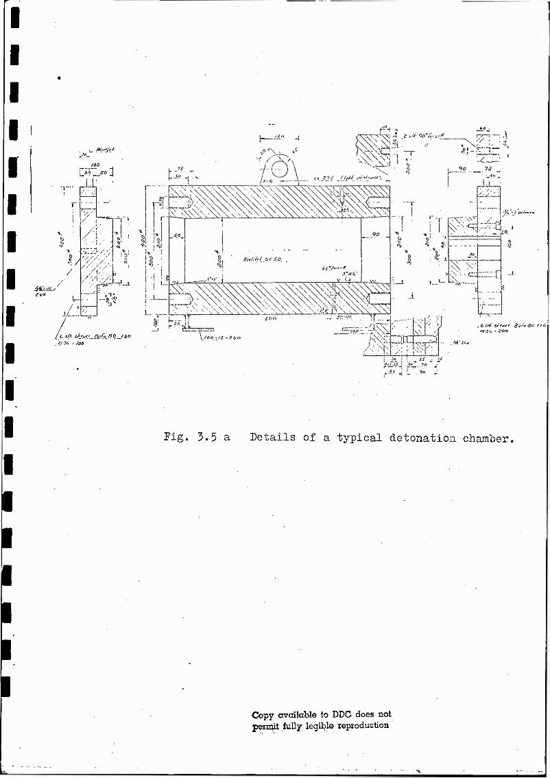
zoo
J-i
3/1 /
■i/-
l— / *
/ i
''A ■■/■
■>Q:—r v-z
Fig. 3.5 a Details of a typical detonation chamber.
Copy available to DDC does not permit fully legible reproduction

I Ifri i .-M IP i "">
J !i ■•• i| * •v. ;
i
[finite] J. J. t e"rf?3
•• . 1 S"M "■'*? IÜ
9» S" I »* »* ' 7
•> .. i ^ -: S «* * , -„v
-5 I O *
. ^ * N( ■*.
'"V -■; '.;> • V V\ * V .
sCv^s; x f \" ^ \\ \ *' V
j *\\ ' V
0' CD: Pi,
■ \'
:->v : j 1 ; <\-:
\ V N ib-s
SR 1 1 h ' J1
S3 4 \
Pig. 3.5 b Details of insertions in detonation chamber.
Copy available to DDC does not permit fully legible reproduction

v- i->> \ \ ,:. ^^-y. x
X. \ i
v>?v / i > V '/' - It? ;'ji
'■?,'•' '-'irr'".!1 ''.'"■' ' ! i J i . . -j ! ; •
*S//^J
! ; ' I I UtX-l .1 I I 1
, 5 !
! i ! k!i|*Ji!?rJ i > 11 ■;|;i;|:iF!4ii:5i':hijüL..
i f- f 'Mi
?!•* 2 «r5
0
®
~L
©4 i
®r J ' !£' 1 I
i i
♦! iDj . C
%H--4-
.<l •5,-3
©
•v. r~cr —i
-t
©
(?)
4.: 5| 0-t i
Oi . I
^ ,
(V)
\
fs"!
r~ " »■/""
n 2 > ! ; i
;1
©r ^r~ T -I I
<J" I
©
; ..[
f" "I
'0- V
I
a( ©-•
h : _J
S'E
„j-- ,ij I. «j
* 53 . I i
JLU«,
j I+-+--
-^ j"'
©
.. . as f - i
£V r?2"i |
-J.
Fig. 3.5 c Details of tube connections.
.Copy available to DDC does not penrit fully legible reproduction

Detonation enr.mber
Scale 1:1
Silicon oil
_ Adapter (steel)
— Kistler pressure gauge
Fig. 4.1 a Heat protection of transducer in detonation chamber.
Adapter
2 ram Silicon rubber
Fig. 4.1 b Section of tunnel with pressure transducer.

I I CHARGE CALIBRATOR
KISTLER
r
PRESSURE TRANSDUCERS
KISTLER 603 B, 601 H, and 6201
V CHARGE AMPLIFIER
KISTLER 566, 568 or 504 A
1
1 OSCILLOSCOPE
TEKTRONIX 502 A
POLAROID CAMERA
MEASURING MODE A
r TIME-MARK GENERATOR
HP
i ANALOG TAPE RECORDER
AMP EX FR 1300 A
GALVANOMETER AMPLIFIER
KISTLER 5211
i U0Vo WRITER'
CEC 12^-5
MEASURING MODE B
FigA.lC: Measuring chain indicating the two different "
modes used in the' tests»
'»»**

<£>