No. OCH515 TECHNICAL & SERVICE MANUAL -...
26
TECHNICAL & SERVICE MANUAL CONTENTS 1. PART NAMES AND FUNCTIONS .......... 2 2. SPECIFICATION ..................................... 5 3. OUTLINES AND DIMENSIONS .............. 7 4. WIRING DIAGRAM ................................. 8 5. REFRIGERANT SYSTEM DIAGRAM .......... 9 6. MICROPROCESSOR CONTROL ......... 10 7. TROUBLESHOOTING .......................... 15 8. DISASSEMBLY PROCEDURE ............. 22 Indoor unit [Model names] [Service Ref.] PKFY-P08NHMU-E2 PKFY-P08NHMU-E2 PKFY-P12NHMU-E2 PKFY-P12NHMU-E2 PKFY-P15NHMU-E2 PKFY-P15NHMU-E2 PKFY-P18NHMU-E2 PKFY-P18NHMU-E2 No. OCH515 INDOOR UNIT SPLIT-TYPE, HEAT PUMP AIR CONDITIONERS R22 R410A Note: • This manual describes only service data of the indoor units. • RoHS compliant products have <G> mark on the spec name plate. April 2012 PARTS CATALOG (OCB515)
Transcript of No. OCH515 TECHNICAL & SERVICE MANUAL -...
TECHNICAL & SERVICE MANUAL
CONTENTS
1. PART NAMES AND FUNCTIONS .......... 22. SPECIFICATION .....................................53. OUTLINES AND DIMENSIONS ..............74. WIRING DIAGRAM .................................85. REFRIGERANT SYSTEM DIAGRAM ..........96. MICROPROCESSOR CONTROL .........107. TROUBLESHOOTING ..........................158. DISASSEMBLY PROCEDURE .............22
Indoor unit[Model names] [Service Ref.]PKFY-P08NHMU-E2 PKFY-P08NHMU-E2PKFY-P12NHMU-E2 PKFY-P12NHMU-E2PKFY-P15NHMU-E2 PKFY-P15NHMU-E2PKFY-P18NHMU-E2 PKFY-P18NHMU-E2
No. OCH515
INDOOR UNIT
SPLIT-TYPE, HEAT PUMP AIR CONDITIONERS
R22R410A
Note:• This manual describes
only service data of the indoor units.
• RoHS compliant products have <G> mark on the spec name plate.
April 2012
PARTS CATALOG (OCB515)

2
1 PART NAMES AND FUNCTIONS
Indoor unitFilter Air intake
Louver Air outlet Vane
Use the specifi ed refrigerant onlyNever use any refrigerant other than that specifi ed.Doing so may cause a burst, an explosion, or fi re when the unit is being used, serviced, or disposed of.Correct refrigerant is specifi ed in the manuals and on the spec labels provided with our products.We will not be held responsible for mechanical failure, system malfunction, unit breakdown or accidents caused by failure to follow the instructions.
OCH515
33
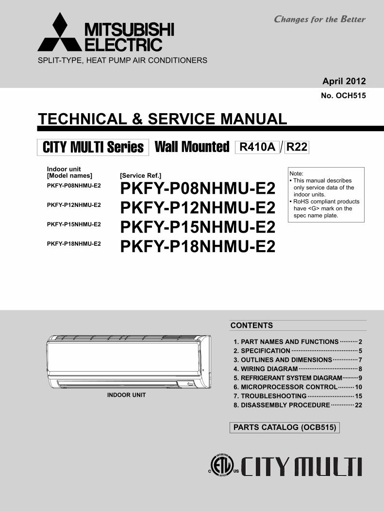
Wireless remote controller
ON/OFF TEMP
FAN
VANE
TEST RUN
AUTO STOP
AUTO START
h
min
LOUVER
MODE
CHECK
RESETSET CLOCK
MODEL SELECT
NOT AVAILABLE
CHECK TEST RUN°C
AMPM
AMPM
°F
VANE CONTROL buttonUsed to change the air flow direction.
CLOCK buttonRESET button
SET button
ON/OFF buttonThe unit is turned ON and OFF alternately each time the button is pressed.
LOUVER buttonChanges left/right airflow direction.
(Not available for this model.)
MODE SELECT buttonUsed to switch the operation mode between cooling, drying, fan, heating and auto mode.
CHECK-TEST RUN buttonOnly press this button to perform an inspection check or test operation.Do not use it for normal operation.
FAN SPEED SELECT buttonUsed to change the fan speed.
TIMER displayDisplays when in timer operation or when setting timer.
buttonSET TEMPERATURE button sets any desired room temperature.
CLOCK displayDisplays the current time.
“ ” “ ” displayDisplays the order of timer operation.
“ ” “ ” displayDisplays whether timer is on or off.
In case the outdoor unit is cool only type, the heating and auto mode are not available.
Buttons used to set the “hour and minute” of the current time and timer settings.
h and min buttons
display
displayFAN SPEED display indicates which fan speed has been selected.
displayThe vertical direction of air flow is indicated.
displayBlinks when model is selected.
displaydisplay
CHECK and TEST RUN display indicate that the unit is being checked or test-run.
displayOPERATION MODE displayOperation mode display indicates which operation mode is in effect.
TIMER CONTROL buttonsAUTO STOP (OFF timer): when this switch is set, the air conditioner will be automatically stopped at the preset time.AUTO START (ON timer): when this switch is set, the air conditioner will be automatically started at the preset time.
MODEL SELECT
CHECK TEST RUN
SET TEMP. display indicates the set desired temperature.
Lights up while the signal is transmitted to the indoor unit when the button is pressed.
OCH515
4
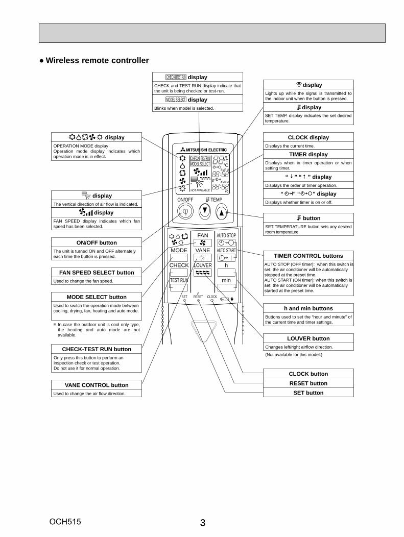
Wired remote controller
°F°C°F°C
ERROR CODEAFTERTIMERTIME SUN MON TUE WED THU FRI SAT
ONOFF
HrAFTER
FILTERFUNCTION
ONLY1Hr.
WEEKLYSIMPLE
AUTO OFF
PAR-21MAA
ON/OFF
FILTER
CHECK
OPERATION CLEAR
TEST
TEMP.
MENU
BACK DAYMONITOR/SET
CLOCK
ON/OFF
Display Section
For purposes of this explanation,all parts of the display are shownas lit. During actual operation, onlythe relevant items will be lit.
Identifies the current operation Shows the operating mode, etc.*Multilanguage display is available.
“Centrally Controlled” indicatorIndicates that operation from the remote controller has been prohib-ited by a master controller.
“Timer is Off” indicatorIndicates that the timer is off.
Temperature SettingShows the target temperature.
Day-of-WeekShows the current day of the week.
Time/Timer DisplayShows the current time, unless the simple or Auto Offtimer is set.If the simple or Auto Off timer is set, the time to be switched off is shown.
“Sensor” indicationDisplayed when the remote controllersensor is used.
“Locked” indicatorIndicates that remote controller but-tons have been locked.
“Clean The Filter” indicatorTo be displayed on when it is time to clean the filter.
Timer indicatorsThe indicator comes on if the corre-sponding timer is set.
Up/Down Air Direction indica-torThe indicator shows the direc-tion of the outcoming airflow.
“One Hour Only” indicator
Room Temperature displayShows the room temperature. The roomtemperature display range is 46–102°F.The display blinks if the temperatureis less than 46°F or 102°F or more.
Louver displayIndicates the action of the swing louver.Does not appear if the louver is notrunning.
(Power On indicator)Indicates that the power is on.
Fan Speed indicatorShows the selected fan speed.
Ventilation indicatorAppears when the unit is running inVentilation mode.
Operation Section
Temperature setting buttons
Down
Up
Timer Menu button(Monitor/Set button)
Mode button (Return button)
Set Time buttons
Back
Ahead
Timer On/Off button(Set Day button)
Opening thecover
ON/OFF button
Fan Speed button
Filter button(<Enter> button)
Test Run button
Check button (Clear button)
Airflow Up/Down button
Louver button( Operation button)
To return operationnumber
Ventilation button( Operation button)
To go to next operationnumber
Built-in temperature sensor
Displayed if the airflow is set toLow or downward during COOLor DRY mode. (Operation variesaccording to model.)The indicator goes off in one hour,at which time the airflow direction also changes.
Note:The phrase "Wired remote controller" in this manual refers only to the PAR-21MAA.If you need any information for the other remote controller, please refer to either the installation manual or initial setting manual which are included in remote controller's box.
OCH515
55
4.415,0000.030.305.0
17,0000.030.30
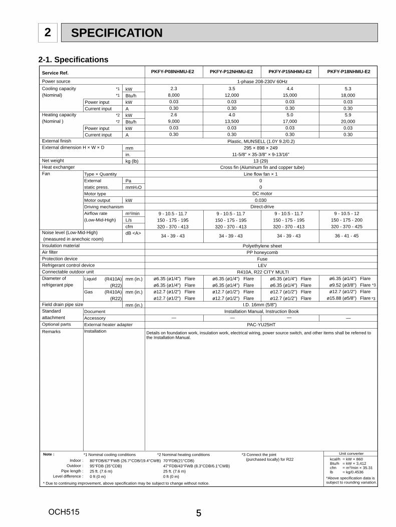
Note : Unit converterkcal/h = kW × 860Btu/h = kW × 3,412cfm = m3/min × 35.31lb = kg/0.4536
*Above specification data is subject to rounding variation.
Service Ref.
Power sourceCooling capacity (Nominal)
Heating capacity(Nominal )
External finishExternal dimension H × W × D
Net weightHeat exchangerFan
Noise level (Low-Mid-High) (measured in anechoic room)Insulation materialAir filterProtection deviceRefrigerant control deviceConnectable outdoor unitDiameter of refrigerant pipe
Field drain pipe sizeStandardattachmentOptional parts
Remarks
Power inputCurrent input
Power inputCurrent input
Type × QuantityExternalstatic press.Motor typeMotor outputDriving mechanismAirflow rate(Low-Mid-High)
Liquid
Gas
DocumentAccessoryExternal heater adapterInstallation
kWBtu/hkWAkWBtu/hkWA
mmin.kg (lb)
PammH2O
kW
m3/minL/scfmdB <A>
mm (in.)
mm (in.)
mm (in.)
*1*1
*2*2
(R410A)(R22)
(R410A)(R22)
Installation Manual, Instruction Book
PAC-YU25HT
1-phase 208-230V 60Hz
Cross fin (Aluminum fin and copper tube)
DC motor
Direct-drive
Polyethylene sheetPP honeycomb
FuseLEV
R410A, R22 CITY MULTI
PKFY-P12NHMU-E2
Plastic, MUNSELL (1.0Y 9.2/0.2)
3.512,0000.030.304.0
13,5000.030.30
295 × 898 × 24911-5/8" × 35-3/8" × 9-13/16"
13 (29)
Line flow fan × 100
0.030
PKFY-P15NHMU-E2
9 - 10.5 - 12150 - 175 - 200320 - 370 - 425
36 - 41 - 45
I.D. 16mm (5/8")
ø6.35 (ø1/4")ø6.35 (ø1/4")ø12.7 (ø1/2")ø12.7 (ø1/2")
FlareFlareFlareFlare
ø6.35 (ø1/4")ø6.35 (ø1/4")ø12.7 (ø1/2")ø12.7 (ø1/2")
FlareFlareFlareFlare
PKFY-P18NHMU-E2
5.318,0000.030.305.9
20,0000.030.30
9 - 10.5 - 11.7150 - 175 - 195320 - 370 - 413
34 - 39 - 43
PKFY-P08NHMU-E2
2.38,0000.030.302.6
9,0000.030.30
ø6.35 (ø1/4")ø6.35 (ø1/4")ø12.7 (ø1/2")ø12.7 (ø1/2")
FlareFlareFlareFlare
9 - 10.5 - 11.7150 - 175 - 195320 - 370 - 413
34 - 39 - 43
ø6.35 (ø1/4")ø9.52 (ø3/8")ø12.7 (ø1/2")
ø15.88 (ø5/8")
FlareFlareFlareFlare
——— —
9 - 10.5 - 11.7150 - 175 - 195320 - 370 - 413
34 - 39 - 43
*3
*1 Nominal cooling conditionsIndoor :
Outdoor :Pipe length :
Level difference :
80°FDB/67°FWB (26.7°CDB/19.4°CWB)95°FDB (35°CDB)25 ft. (7.6 m)0 ft (0 m)
*2 Nominal heating conditions70°FDB(21°CDB)47°FDB/43°FWB (8.3°CDB/6.1°CWB)25 ft. (7.6 m)0 ft (0 m)
*3 Connect the joint (purchased locally) for R22
* Due to continuing improvement, above specification may be subject to change without notice.
*3
Details on foundation work, insulation work, electrical wiring, power source switch, and other items shall be referred to the Installation Manual.
2 SPECIFICATION
2-1. Specifi cations
OCH515

6
Parts name
Service Ref.Symbol
TH21
TH22
TH23TH24
FUSE
MF
MV
LEV
TB2
TB5
TB15
Resistance 30°F/15.8k , 50°F/9.6k , 70°F/6.0k , 80°F/4.8k , 90°F/3.9k , 100°F/3.2k
Resistance 30°F/15.8k , 50°F/9.6k , 70°F/6.0k , 80°F/4.8k , 90°F/3.9k , 100°F/3.2k
Resistance 30°F/15.8k , 50°F/9.6k , 70°F/6.0k , 80°F/4.8k , 90°F/3.9k , 100°F/3.2k
250V 3.15A
8-Pole Output 30W / RCOJ30-CK
MSFBC20 DC12V
(L1, L2, GR) 250V 20A
(M1, M2, S) 250V 20A
(1, 2) 250V 10A
Liquid pipe thermistor
Gas pipe thermistor
Linear expansion valve
PKFY-P08NHMU-E2 PKFY-P12NHMU-E2 PKFY-P15NHMU-E2
Room temperaturethermistor
Fuse(Indoor controller board)
Fan motor
Vane motor(with limit switch)
Power supply terminalblock
Transmission terminalblock
DC12V Stepping motor drivePort 3.2 (0~2000pulse)
PKFY-P18NHMU-E2
MA remote controllerterminal block
PKFY-P08, 12, 15NHMU-E2External static pressure : 0PaPower source : 208,230V, 60Hz
* Measured in anechoic room.
OC
TAV
E B
AN
D P
RE
SS
UR
E L
EV
EL
(dB
) 0dB
= 2
0P
a
3.3
ft.(1
m)
Measurement location
PKFY-P12NHMU-E2PKFY-P15NHMU-E2PKFY-P18NHMU-E2
34-39-43
36-41-45
Sound level dB (A)Sound level at anechoic room : Low-Middle-High
Service Ref.PKFY-P08NHMU-E2
Approximate minimumaudible limit oncontinuous noise
High speedLow speed
3.3 ft.(1m)
OCTAVE BAND CENTER FREQUENCIES(Hz)
PKFY-P18NHMU-E2 External static pressure : 0PaPower source : 208,230V, 60Hz
OC
TAV
E B
AN
D P
RE
SS
UR
E L
EV
EL
(dB
) 0dB
= 2
0P
a
OCTAVE BAND CENTER FREQUENCIES(Hz)
Approximate minimumaudible limit oncontinuous noise
10.0
15.0
20.0
25.0
30.0
35.0
40.0
45.0
50.0
55.0
60.0
65.0
70.0
63 125 250 500 1k 2k 4k 8k
NC60
NC50
NC40
NC30
NC20
High speedMiddle speedLow speed
10.0
15.0
20.0
25.0
30.0
35.0
40.0
45.0
50.0
55.0
60.0
65.0
70.0
63 125 250 500 1k 2k 4k 8k
NC60
NC50
NC40
NC30
NC20
2-2. Electrical parts specifi cations
2-3. Sound levels
2-4. NC curves
OCH515
77
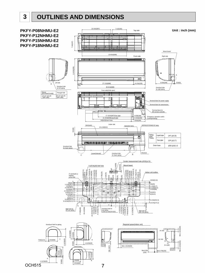
OUTLINES AND DIMENSIONS3
1/2F ( 12.7)
1/4F ( 6.35)Refrig-erartPiping
Drain hose
Gas pipe
Liquid pipe
2-1/2~ 3-1/8 ( 65~ 80)
2-1/2~ 3-1/8 ( 65~ 80)
Through holeSleeve(purchased locally)
Center measurement hole 3/32( 2.5)
5/32
(3.8
)
2-1/
4(58
)
0
Wall hole forleft rear piping
Knockout hole forrear piping2-3/4×12-3/16(70×310) Wall hole for
right rear piping
77- 3/16( 5.1)Tappingscrew hole
4- 5/16( 9) Bolt hole Mount board
Indoor unit outline
05/8(16)
9-15/16(253.5)9-1/8(232.5)
1-1/16(28.5)1-9/16(41)
3-1/16(78.5)
4-1/16(103.5)4-9/16(116)6-1/2(166)
7(178.5)8(203.5)
3-9/16(91)
13/16(21.8)
9-1/16(231.5)
10-3/4(273.2)
0
1-1/4(32.7)
2-9/16(66)2-1/16(53.5)
5(128.5)6(153.5)
3/4(20)
9/16
(15)
14-5
/8(3
72.3
)14
(356
.3)
12-7
/8(2
37.5
)
11-7
/16(
291.
5)10
-3/8
(265
)9-
5/16
(238
)8-
13/1
6(22
5)7-
13/1
6(20
0)
4-7/
8(12
5)
2-3/
4(70
)
9/16
(15)
14-5
/8(3
72.3
)14
(356
.3)
12-7
/8(3
27.5
)
10-3
/8(2
65)
11-7
/16(
291.
5)
7-13
/16(
200)
8-13
/16(
225)
4-7/
8(12
5)
2-3/
4(70
)
0
17-5
/8(4
49)
7-9/
16(1
93.5
)7-
1/16
(180
.3)
6-9/
16(1
67)
5-1/
2(14
0)4-
1/2(
115)
6-13
/16(
174)
8-3/
8(21
3)9-
5/16
(238
)10
-15/
16(2
78.3
)
15-1
/2(3
94)
11-1
/16(
281)
17-5
/8(4
49)
0
Emergency operation switch(cooling/heating)
Terminal block for MA-remote controller
Terminal block for transmission
Front side(Grille open)
Terminal block for power supply
17-15/16(457)Gas pipe21-3/16(539)Liquid pipe
6-5/8(169)6-3/16(158)
24(610)Drain hose 7-3/16(184)
Required space(Indoor unit)
Air inlet
Air inlet
Air outlet
Min
.1-3
1/32
(50)
Min
.9-1
3/16
(250
)
Min.5-7/8(150)Min.8-5/8(220)
Min.1-31/32(50)
Min
.1/4
(7)
Knockout hole for piping
D
2-3/
16(5
6)
2-11
/16(
69)
3/16
(6)
1-11/16(43)
C2-3/16(56)7/16(12.5)
1-11
/16(
43)
B1-3/4(46)
2-5/16(60)
2-5/
16(5
9)
1-11
/16(
43)
A
1-11/16(43)
1-3/
4(46
)2-
3/16
(56)
3/16
(6)
A
Knockout holefor right piping
Right side
Mount board
3/16(5)9-3/4(249)
Top side15-3/16(387) 7-1/2(192)
7-3/
4(19
7)
23-9/16(599)
C B
Operation lamp DEFROST/STAND BY lamp
ReceiverLouver(manual)
Vane(auto)
Knockout holefor lower piping
Knockout holefor lower piping
Under side
5/16
(8) 24-1/16(612)
DKnockout holefor left piping
Left side
Front side
6-1/16(155)2-1/8(55)
27-1/16(688)
11-9
/16(
295)
35-5/16(898)
5/8 ( 16) I.D
PKFY-P08NHMU-E2PKFY-P12NHMU-E2PKFY-P15NHMU-E2PKFY-P18NHMU-E2
Unit : inch (mm)
OCH515

8
WIRING DIAGRAM4
<fig: 1>Models
P08
SW2
123456
ONOFF
P12123456
ONOFF
P15123456
ONOFF
P18123456
ONOFF
The black square ( ) indicates a switch position.
FANCNMF(WHT)
1 63
MS3~
M
VANECN151(WHT)
5 1 LEVCN60(YLW)
6
6
1CNRU(WHT)
LDSWE (A)(BLU)
6 1
3
3
15 1
5 1
4 1
4 1
2 1
2 1
3 1
4 18 1
1 3
51
1 3
1 2 1 2 3 4 5 6 7 8
SW3
1 2 3 4 5 6
SW2 ONOFF
ONOFF
1 2 3 4
SW4
2 1
11
2
2
3
3
4 5 6 7 8 910
SW1
SWA
L1L2
LED1X1
LED2
M
FUSE
CND(BLK)
CNP(BLU)
RED
BLU
YLW
BLK
WHT
MF MV LEV
SWE
OFF
BZ1
ON
BLU
TB2
RED
RED
BLU
BLU
YLW
WHT
ORN
ORN
ORN
ORNYLW
BLU
BRN
BRN
RED
GRN/YLW
RED
BLU
BLK
I.B S.BW.B
A.B
PULLBOX
FUSE(16A)
BREAKER(16A)
TO NEXT INDOOR
UNIT
POWER SUPPLY 208/230V 60Hz
GRN
CN52(GRN)
LD SWE (B)LD101 (B)
SWE1LED1
TH24
TH23
TH22
TH21
LED2SWE2
CN51(WHT)
CN24(YLW)
FLOAT SWCN4F(WHT)
LIQUID/GAS1CN44(WHT)
INTAKECN20(RED)
ADDRESSCN81(RED)
ADDRESSCN42(RED)
GAS2CN2G(BLK)
ADDRESSCN43(RED)
ADDRESSCN82(RED)
MA-REMOCONCN3A(BLU)
M-NETCN2M (BLU)
CN32(WHT)
RU
4
8
t○
t○
t○
t○
See fig: 1
TB5(SHIELD)
M1M2
TB151
S
2TO MA-REMOTECONTROLLERDC8.7-13V
TO OUTDOOR UNITBC CONTROLLERREMOTE CONTROLLERDC24-30V
0123456789AB
CD
EF0 1
23
456
78
90 1
23
456
78
9
SW14SW11SW12
10thsDIGIT
1sDIGIT
BRANCHNo.
GR
< 2>
A.B ADDRESS BOARD
S.B SWITCH BOARD
W.B PCB FOR WIRELESS REMOTE CONTROLLER
SW1SWA
SW11SW12
MODE SELECTIONFAN SPEED SELECTOR
ADDRESS SETTING 1s DIGIT
SWE1SWE2
EMERGENCY OPERATION(HEAT)EMERGENCY OPERATION(COOL)
LED(OPERATION INDICATOR:GREEN)LED(OPERATION FOR HEATING :ORANGE )RECEIVING UNIT
ADDRESS SETTING 10ths DIGITSW14 BRANCH No.
SWITCH
LED1LED2RU
SYMBOL NAMETH21 THERMISTOR ROOM TEMP. DETECTION
(32°F/15k ,77°F/5.4kΩ)PIPE TEMP. DETECTION / LIQUID(32°F/15k ,77°F/5.4kΩ)PIPE TEMP. DETECTION / GAS1(32°F/15k ,77°F/5.4kΩ)
TH22
TH23
PIPE TEMP. DETECTION / GAS2(32°F/15k ,77°F/5.4kΩ)
TH24
NOTES:1.At servicing for outdoor unit, always follow the wiring diagram of outdoor unit.2.In case of using MA-Remote controller, please connect to TB15. (Remote controller wire is non-polar.)3.In case of using M-NET, please connect to TB5. (Transmission line is non-polar.)4.Symbol [S] of TB5 is the shield wire connection.5.Symbols used in wiring diagram above are, : terminal block, :connecter.6.The setting of the SW2 dip switches differs in the capacity. For the detail, refer to the fig: 1.
Mark Meaning Function
Power supply forMA-Remote controller
Main power supply (Indoor unit: 208-230V)Power on → Iamp is lit
LED on indoor board for service
LED1 Main power supply
Power supply for MA-Remote controlleron → Iamp is litLED2
< 2>Use copper supply wires.
SYMBOL NAMEI.B INDOOR CONTROLLER BOARD
BZ1
CN32CN51CN52
CONNECTOR
BUZZER
REMOTE SWITCHCENTRALLY CONTROLREMOTE INDICATION
X1 AUX.RELAY
FUSE FUSE (T3.15AL 250V)LED1 POWER SUPPLY (I.B)LED2 POWER SUPPLY (I.B)
MFMV
LEV LINEAR EXPANSION VALVEFAN MOTORVANE MOTOR
DRAIN PUMP
TB2TB5TB15
TRANSMISSIONMA-REMOTE CONTROLLER
TERMINALBLOCK
POWER SUPPLY
SW2SW3SW4SWE
CAPACITY CODEMODE SELECTIONMODEL SELECTORDRAIN PUMP (TEST MODE)
SWITCH
EXTERNAL HEATERCN24
PKFY-P08NHMU-E2PKFY-P12NHMU-E2PKFY-P15NHMU-E2PKFY-P18NHMU-E2
OCH515
9
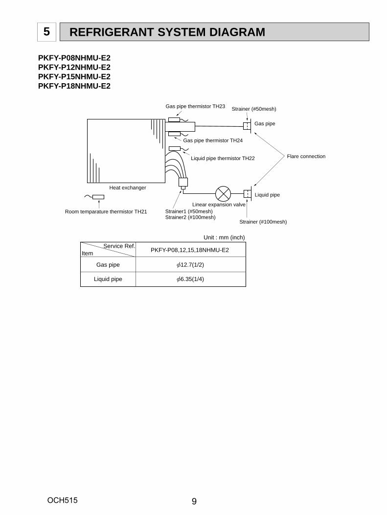
5 REFRIGERANT SYSTEM DIAGRAM
Strainer (#50mesh)
Strainer (#100mesh)
Strainer1 (#50mesh)Strainer2 (#100mesh)
Heat exchanger
Room temparature thermistor TH21
Gas pipe thermistor TH23
Liquid pipe thermistor TH22
Linear expansion valve
Gas pipe
Liquid pipe
Flare connection
Gas pipe
Liquid pipe
PKFY-P08,12,15,18NHMU-E2
12.7(1/2)
6.35(1/4)
ItemService Ref.
Unit : mm (inch)
Gas pipe thermistor TH24
PKFY-P08NHMU-E2PKFY-P12NHMU-E2PKFY-P15NHMU-E2PKFY-P18NHMU-E2
OCH515
10
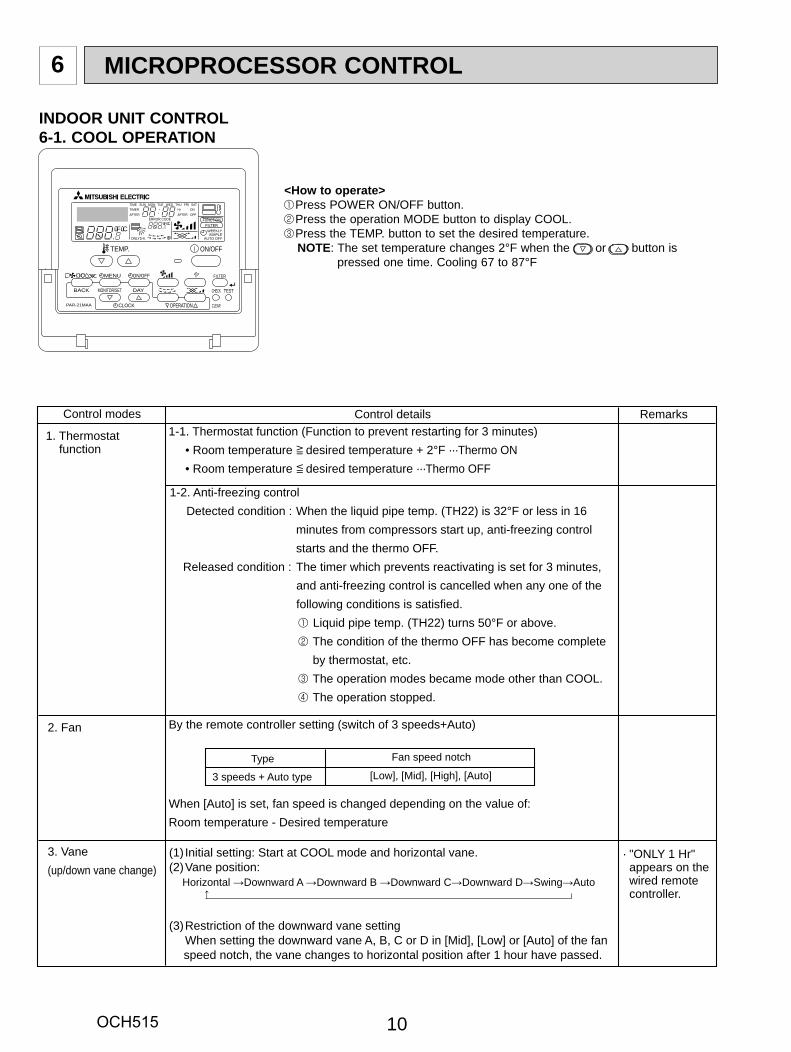
6 MICROPROCESSOR CONTROL
PAR-21MAA
ON/OFF
FILTER
CHECK
OPERATION CLEAR
TEST
TEMP.
MENU
BACK DAYMONITOR/SET
CLOCK
ON/OFF
ûFûCûFûC
ERROR CODEAFTERTIMERTIME SUN MON TUE WED THU FRI SAT
ONOFF
HrAFTER
FILTERFUNCTION
ONLY1Hr.
WEEKLYSIMPLE
AUTO OFF
INDOOR UNIT CONTROL6-1. COOL OPERATION
<How to operate> Press POWER ON/OFF button. Press the operation MODE button to display COOL. Press the TEMP. button to set the desired temperature.NOTE: The set temperature changes 2°F when the or button is
pressed one time. Cooling 67 to 87°F
Control modes Control details1-1. Thermostat function (Function to prevent restarting for 3 minutes) • Room temperature desired temperature + 2°F ···Thermo ON • Room temperature desired temperature ···Thermo OFF
1-2. Anti-freezing control Detected condition : When the liquid pipe temp. (TH22) is 32°F or less in 16 minutes from compressors start up, anti-freezing control starts and the thermo OFF. Released condition : The timer which prevents reactivating is set for 3 minutes, and anti-freezing control is cancelled when any one of the following conditions is satisfied. Liquid pipe temp. (TH22) turns 50°F or above. The condition of the thermo OFF has become complete by thermostat, etc. The operation modes became mode other than COOL. The operation stopped.
By the remote controller setting (switch of 3 speeds+Auto)
When [Auto] is set, fan speed is changed depending on the value of:Room temperature - Desired temperature
2. Fan
1. Thermostat function
Remarks
Type Fan speed notch
[Low], [Mid], [High], [Auto]3 speeds + Auto type
→
(1) Initial setting: Start at COOL mode and horizontal vane.(2) Vane position:
Horizontal →Downward A →Downward B →Downward C→Downward D→Swing→Auto
(3) Restriction of the downward vane setting When setting the downward vane A, B, C or D in [Mid], [Low] or [Auto] of the fan speed notch, the vane changes to horizontal position after 1 hour have passed.
3. Vane (up/down vane change)
· "ONLY 1 Hr" appears on the wired remote controller.
OCH515
1111
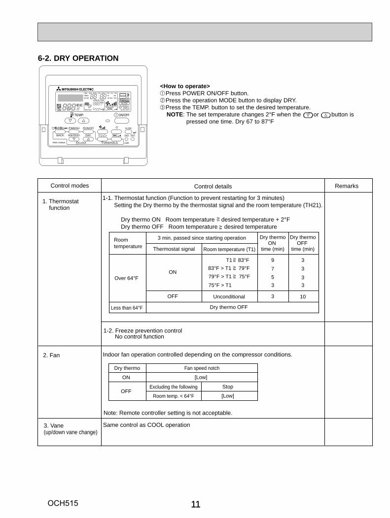
Control modes Control details
1-1. Thermostat function (Function to prevent restarting for 3 minutes)Setting the Dry thermo by the thermostat signal and the room temperature (TH21).
Dry thermo ON Room temperature desired temperature + 2°F Dry thermo OFF Room temperature desired temperature
1-2. Freeze prevention control No control function
Indoor fan operation controlled depending on the compressor conditions.
1. Thermostat function
Remarks
Roomtemperature
3 min. passed since starting operation
Thermostat signal Room temperature (T1)
Dry thermoON
time (min)
Dry thermoOFF
time (min)
Less than 64°F
Over 64°FON
OFF
T1 83°F83°F > T1 79°F79°F > T1 75°F75°F > T1
Unconditional
9 37 35 33 3
103
Dry thermo OFF
2. Fan
Note: Remote controller setting is not acceptable.
Dry thermo Fan speed notch
Excluding the following
Room temp. < 64°F
ON
OFF
[Low]
[Low]
Stop
3. Vane (up/down vane change)
Same control as COOL operation
PAR-21MAA
ON/OFF
FILTER
CHECK
OPERATION CLEAR
TEST
TEMP.
MENU
BACK DAYMONITOR/SET
CLOCK
ON/OFF
ûFûCûFûC
ERROR CODEAFTERTIMERTIME SUN MON TUE WED THU FRI SAT
ONOFF
HrAFTER
FILTERFUNCTION
ONLY1Hr.
WEEKLYSIMPLE
AUTO OFF
6-2. DRY OPERATION
<How to operate> Press POWER ON/OFF button. Press the operation MODE button to display DRY. Press the TEMP. button to set the desired temperature.NOTE: The set temperature changes 2°F when the or button is
pressed one time. Dry 67 to 87°F
OCH515
12
Control modes Control details
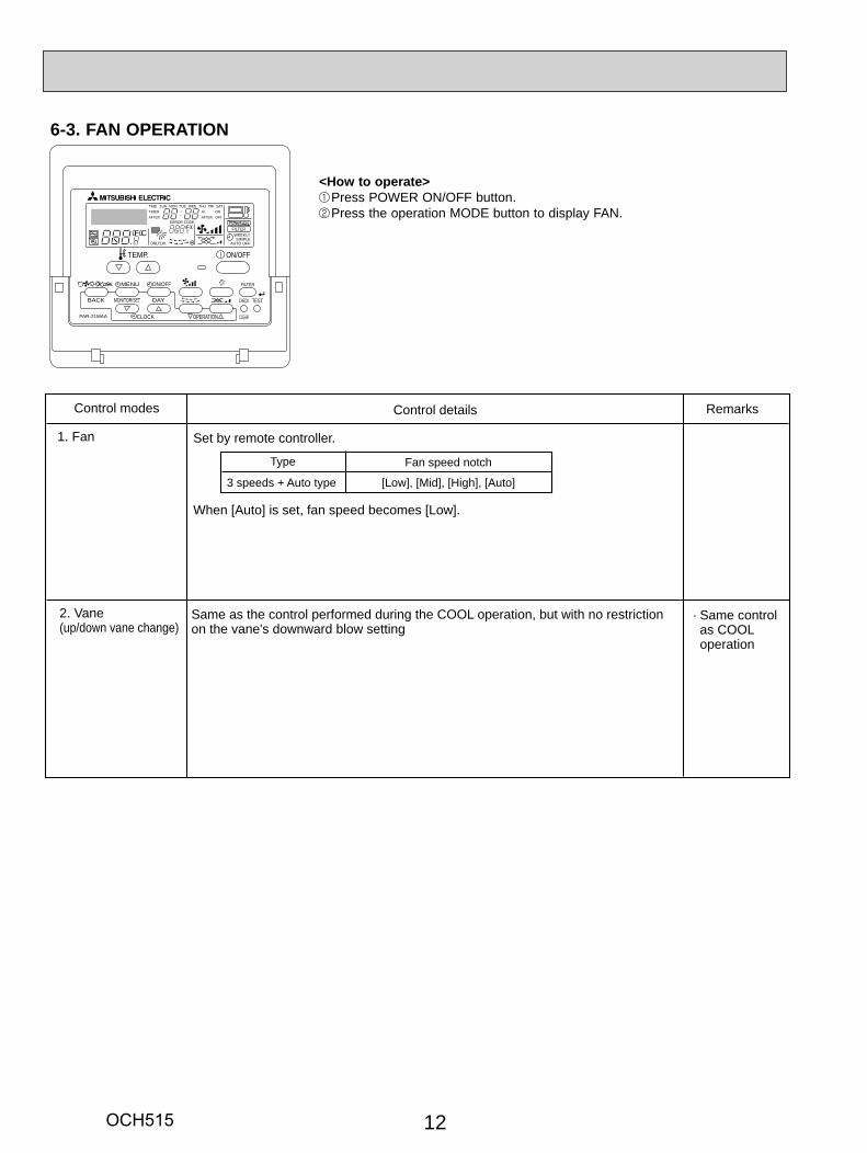
Set by remote controller.
When [Auto] is set, fan speed becomes [Low].
Remarks
1. Fan
Type Fan speed notch
3 speeds + Auto type [Low], [Mid], [High], [Auto]
2. Vane (up/down vane change)
Same as the control performed during the COOL operation, but with no restriction on the vane's downward blow setting
· Same control as COOL operation
PAR-21MAA
ON/OFF
FILTER
CHECK
OPERATION CLEAR
TEST
TEMP.
MENU
BACK DAYMONITOR/SET
CLOCK
ON/OFF
ûFûCûFûC
ERROR CODEAFTERTIMERTIME SUN MON TUE WED THU FRI SAT
ONOFF
HrAFTER
FILTERFUNCTION
ONLY1Hr.
WEEKLYSIMPLE
AUTO OFF
6-3. FAN OPERATION
<How to operate> Press POWER ON/OFF button. Press the operation MODE button to display FAN.
OCH515
13
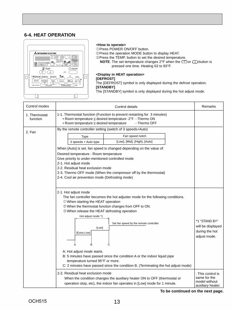
Control modes Control details
1-1. Thermostat function (Function to prevent restarting for 3 minutes) • Room temperature desired temperature -2°F ···Thermo ON
• Room temperature desired temperature ···Thermo OFF
1. Thermostat function
Remarks
2-1. Hot adjust mode The fan controller becomes the hot adjuster mode for the following conditions. When starting the HEAT operation When the thermostat function changes from OFF to ON. When release the HEAT defrosting operation
2. Fan
A: Hot adjust mode starts. B: 5 minutes have passed since the condition A or the indoor liquid pipe temperature turned 95°F or more. C: 2 minutes have passed since the condition B. (Terminating the hot adjust mode)
A CB
[Extra Low]
[Low]Set fan speed by the remote controller
Hot adjust mode *1
2-2. Residual heat exclusion mode When the condition changes the auxiliary heater ON to OFF (thermostat or operation stop, etc), the indoor fan operates in [Low] mode for 1 minute.
· This control is same for the model without auxiliary heater.
*1 "STAND BY"will be displayed during the hot adjust mode.
To be continued on the next page.
By the remote controller setting (switch of 3 speeds+Auto)
When [Auto] is set, fan speed is changed depending on the value of:Desired temperature - Room temperatureGive priority to under-mentioned controlled mode 2-1. Hot adjust mode2-2. Residual heat exclusion mode2-3. Thermo OFF mode (When the compressor off by the thermostat)2-4. Cool air prevention mode (Defrosting mode)
Type Fan speed notch
[Low], [Mid], [High], [Auto]3 speeds + Auto type
PAR-21MAA
ON/OFF
FILTER
CHECK
OPERATION CLEAR
TEST
TEMP.
MENU
BACK DAYMONITOR/SET
CLOCK
ON/OFF
ûFûCûFûC
ERROR CODEAFTERTIMERTIME SUN MON TUE WED THU FRI SAT
ONOFF
HrAFTER
FILTERFUNCTION
ONLY1Hr.
WEEKLYSIMPLE
AUTO OFF
6-4. HEAT OPERATION
<How to operate> Press POWER ON/OFF button. Press the operation MODE button to display HEAT. Press the TEMP. button to set the desired temperature.NOTE: The set temperature changes 2°F when the or button is
pressed one time. Heating 63 to 83°F.
<Display in HEAT operation>[DEFROST]The [DEFROST] symbol is only displayed during the defrost operation.[STANDBY]The [STANDBY] symbol is only displayed during the hot adjust mode.
OCH515
14
→
Control modes Control details
2. Fan
Remarks
2-3. Thermo OFF mode When the thermostat function changes to OFF, the indoor fan operates in [Extra low].
2-4. Heat defrosting mode The indoor fan stops.
(1) Initial setting: OFF → HEAT···[last setting] When the last setting is [Swing] ··· [Downward D] When changing the mode from exception of HEAT to HEAT operation ···[Downward D](2) Vane position:
Horizontal →Downward A →Downward B →Downward C→Downward D→Swing→Auto
(3) Restriction of vane position The vane is horizontally fixed for the following modes. (The control by the remote controller is temporally invalidated and control by the unit.) •Thermo OFF •Hot adjust [Extra low] mode •Heat defrost mode
3. Vane control (Up/down vane change)
From the preceding page
Control modes Control details
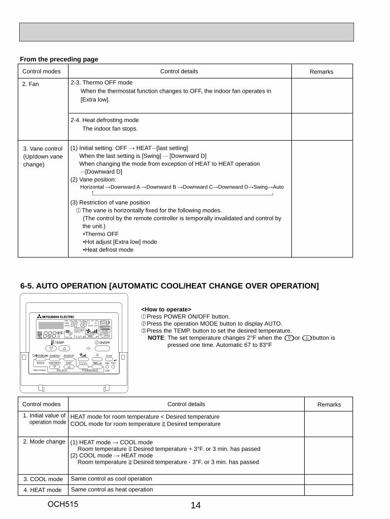
HEAT mode for room temperature < Desired temperatureCOOL mode for room temperature Desired temperature
(1) HEAT mode → COOL mode Room temperature Desired temperature + 3°F. or 3 min. has passed (2) COOL mode → HEAT mode Room temperature Desired temperature - 3°F. or 3 min. has passed
1. Initial value of operation mode
Remarks
2. Mode change
Same control as cool operation3. COOL mode
Same control as heat operation4. HEAT mode
PAR-21MAA
ON/OFF
FILTER
CHECK
OPERATION CLEAR
TEST
TEMP.
MENU
BACK DAYMONITOR/SET
CLOCK
ON/OFF
ûFûCûFûC
ERROR CODEAFTERTIMERTIME SUN MON TUE WED THU FRI SAT
ONOFF
HrAFTER
FILTERFUNCTION
ONLY1Hr.
WEEKLYSIMPLE
AUTO OFF
6-5. AUTO OPERATION [AUTOMATIC COOL/HEAT CHANGE OVER OPERATION]
<How to operate> Press POWER ON/OFF button. Press the operation MODE button to display AUTO. Press the TEMP. button to set the desired temperature.NOTE: The set temperature changes 2°F when the or button is
pressed one time. Automatic 67 to 83°F
OCH515

1515
TROUBLESHOOTING7
7-1. HOW TO CHECK THE PARTSPKFY-P08, 12, 15, 18NHMU-E2
Parts name Check points
Disconnect the connector then measure the resistance with a tester.(At the ambient temperature 50°F~86°F)
Disconnect the connector then measure the resistance value with a tester.(Coil temperature 68°F)
Vane motor (MV)
Linear expansion valve (LEV)
Refer to the next page for the details.
Room temperaturethermistor (TH21)Liquid pipe temperaturethermistor (TH22) Gas pipe temperaturethermistor (TH23 ,24)
Normal4.3k ~9.6k
AbnormalOpen or short
Normal
200 ± 10%
Abnormal
(1)-(5)White-Red
(2)-(6)Yellow-Brown
(3)-(5)Orange-Red
(4)-(6)Blue-Brown Open or short
Measure the resistance between the terminals with a tester. (Coil temperature 77°F)
Normal
350 ± 7%
Abnormal
-Brown-Red
-Brown-Orange
-Brown-Yellow
-Brown-Green Open or short
Fan motor (MF)
Red
Yellow Brown
Orange GreenConnect pin No.
M
123456
LEV
White
YellowOrange
BlueRed
Brown
CN60
Refer to 7-1-3.
7-1-2. Liner expansion valve
7-1-1. Thermistor
4 Φ4
3
6
5
Φ3
2 Φ2
1 Φ1
Φ4
Φ3
Φ2
Φ1
Controller board
Drive circuit
Connector(CN60)
DC12V
Brown
Red
Blue
Orange
Yellow
White
M
4
6
23
51
Blue
Brown
Yellow
OrangeRedWhite
Linear expansion valve
<Thermistor characteristic graph>
Room temperature thermistor (TH21)Liquid pipe temperature thermistor (TH22)Gas pipe temperature thermistor (TH23) (TH24)
Thermistor R0=15kΩ ± 3%Fixed number of B=3480 ± 2%
Rt=15exp { 3480( ) }
30°F 15.8kΩ 50°F 9.6kΩ 70°F 6.0kΩ 80°F 4.8kΩ 90°F 3.9kΩ100°F 3.2kΩ
Thermistor for lower temperature
Operation summary of the linear expansion valve• Linear expansion valve open/close through stepping motor after receiving the pulse signal from the indoor controller board.• Valve position can be changed in proportion to the number of pulse signals.<Connection between the indoor controller board and the linear expansion valve>
1273+(t-32)/1.8
1273
0
10
20
30
40
50
0-20 20 40 60 80 100 120
< Thermistor for lower temperature >
Temperature (°F)
Res
ista
nce
(kΩ
)
OCH515
16
654321
LED1kΩ
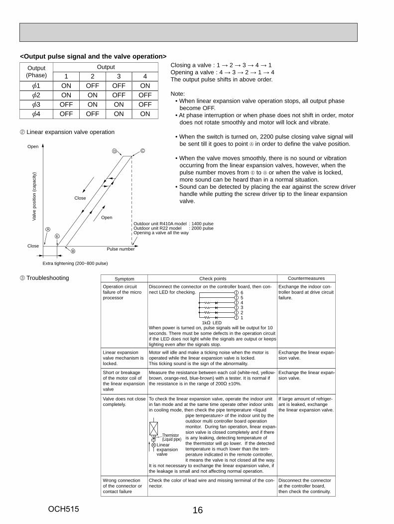
Symptom Check points
Operation circuit failure of the micro processor
Disconnect the connector on the controller board, then con-nect LED for checking.
When power is turned on, pulse signals will be output for 10 seconds. There must be some defects in the operation circuit if the LED does not light while the signals are output or keeps lighting even after the signals stop.
Countermeasures
Exchange the indoor con-troller board at drive circuit failure.
Linear expansion valve mechanism is locked.
Valve does not close completely.
Wrong connection of the connector or contact failure
To check the linear expansion valve, operate the indoor unit in fan mode and at the same time operate other indoor units in cooling mode, then check the pipe temperature <liquid
pipe temperature> of the indoor unit by the outdoor multi controller board operation monitor. During fan operation, linear expan-sion valve is closed completely and if there is any leaking, detecting temperature of the thermistor will go lower. If the detected temperature is much lower than the tem-perature indicated in the remote controller, it means the valve is not closed all the way.
It is not necessary to exchange the linear expansion valve, if the leakage is small and not affecting normal operation.
Thermistor(Liquid pipe)
Linearexpansionvalve
Motor will idle and make a ticking noise when the motor is operated while the linear expansion valve is locked.This ticking sound is the sign of the abnormality.
Check the color of lead wire and missing terminal of the con-nector.
Exchange the linear expan-sion valve.
Exchange the linear expan-sion valve.
If large amount of refriger-ant is leaked, exchange the linear expansion valve.
Disconnect the connector at the controller board, then check the continuity.
Measure the resistance between each coil (white-red, yellow-brown, orange-red, blue-brown) with a tester. It is normal if the resistance is in the range of 200Ω ±10%.
Short or breakage of the motor coil of the linear expansion valve
Output(Phase)
Output
[11
ON[2 ON[3 OFF[4 OFF
2OFFONONOFF
3OFFOFFONON
4ONOFFOFFON
<Output pulse signal and the valve operation>
Linear expansion valve operation
Troubleshooting
D
A
E
B
C
Open
Open
Extra tightening (200~800 pulse)
Pulse number
Outdoor unit R410A model : 1400 pulseOutdoor unit R22 model : 2000 pulseOpening a valve all the way
Close
Close
Valv
e po
sitio
n (c
apac
ity)
Closing a valve : 1 → 2 → 3 → 4 → 1Opening a valve : 4 → 3 → 2 → 1 → 4The output pulse shifts in above order.
Note:• When linear expansion valve operation stops, all output phase
become OFF.• At phase interruption or when phase does not shift in order, motor
does not rotate smoothly and motor will lock and vibrate.
• When the switch is turned on, 2200 pulse closing valve signal will be sent till it goes to point in order to define the valve position.
• When the valve moves smoothly, there is no sound or vibration occurring from the linear expansion valves, however, when the pulse number moves from to or when the valve is locked, more sound can be heard than in a normal situation.
• Sound can be detected by placing the ear against the screw driver handle while putting the screw driver tip to the linear expansion valve.
OCH515

17
7-1-3. DC Fan motor (fan motor/indoor controller circuit board)
Notes · High voltage is applied to the connecter (CNMF) for the fan motor. Pay attention to the service. · Do not pull out the connector (CNMF) for the motor with the power supply on. (It causes trouble of the indoor controller circuit board and fan motor.)Self checkSymptom : The indoor fan cannot turn around.
Yes
NG
NG
NG
Wiring contact checkContact of fan motor connector (CNMF)
Power supply check (Remove the connector (CNMF))Measure the voltage in the indoor controller circuit board.TEST POINT : VDC (between 1 (+) and 3 (-) of the fan connector): VDC DC294~325VTEST POINT : VCC (between 4 (+) and 3 (-) of the fan connector): VCC DC15V
Wiring recovery
Replace indoor controller board.
Replace indoor controller board.
Replace the fan motor
Replace the fan motor
Indoor controller board fuse check
Replace indoor controller board
Replace the fan motor.
Is the voltage normal?
Is there contact failure?
No
Yes
No
NoIs the fuse normal? Replace the fuse
Yes
Check the operation END
OK
Check the operation END
Check the operation END
OK
Check the operation ENDOK
NG
OK
Check method of DC fan motor (fan motor/indoor controller circuit board)
Sensor signal checkMeasure the voltage between CNMF and DC 0V and DC 15V in the indoor controller circuit board.
Does the voltage repeatDC 0V and DC 15V?
No
Yes
OCH515
18
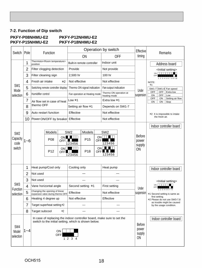
7-2. Function of Dip switch
12345678910
1~6
12345678
Thermistor<Room temperature>position
ON OFF
Filter clogging detection Provide Not provide
Filter cleaning sign 2,500 hr 100 hr
Fresh air intake Not effective Not effective
Switching remote controller display Thermo ON signal indication Fan output indication
Humidifier control Fan operation at Heating mode Thermo ON operation atheating mode
Low 1 Extra low 1
Setting air flow 1 Depends on SW1-7
Auto restart function Effective Not effective
Power ON/OFF by breaker Effective Not effective
Heat pump/Cool only Cooling only Heat pump
Not used
Not used
Vane horizontal angle Second setting 1 First setting
Effective Not effective
Heating 4 degree up Not effective Effective
Target superheat setting 2 —
— —
— —
—
Target subcool 2 — —
ONOFF
1 2 3 4 5 6 7 8
ONOFF
1 2 3 4 5 6 7 8 9 10
Address board<Initial setting>
Indoor controller board
<Initial setting> SW3
Functionselection
Undersuspension
SW2Capacity
code
BeforepowersupplyONswitch
SW1Mode
Effectivetiming
Undersuspensionselection
Switch Pole FunctionOperation by switch
Remarks
Built-in remote controller Indoor unit
Changing the opening of linearexpansion valve during thermo OFF
1SW1-7OFFONOFFON
SW1-8OFFOFFONON
Fan speedExtra lowLowSetting air flow Stop
2 It is impossible to intakethe fresh air.
1 Second setting is same asfirst setting.
2 Please do not use SW3-7,8as trouble might be causedby the usage condition.
Air flow set in case of heatthermo OFF
NOTE:2
Models SW2 Models SW2
P15
P18
P08
P12
123456
ONOFF
123456
ONOFF
123456
ONOFF
123456
ONOFF
Indoor controller board
Indoor controller board
1~4 ONOFF
1 2 3 4
SW4Model
selection
In case of replacing the indoor controller board, make sure to set the switch to the initial setting, which is shown below.
BeforepowersupplyON
PKFY-P08NHMU-E2 PKFY-P12NHMU-E2PKFY-P15NHMU-E2 PKFY-P18NHMU-E2
OCH515
19
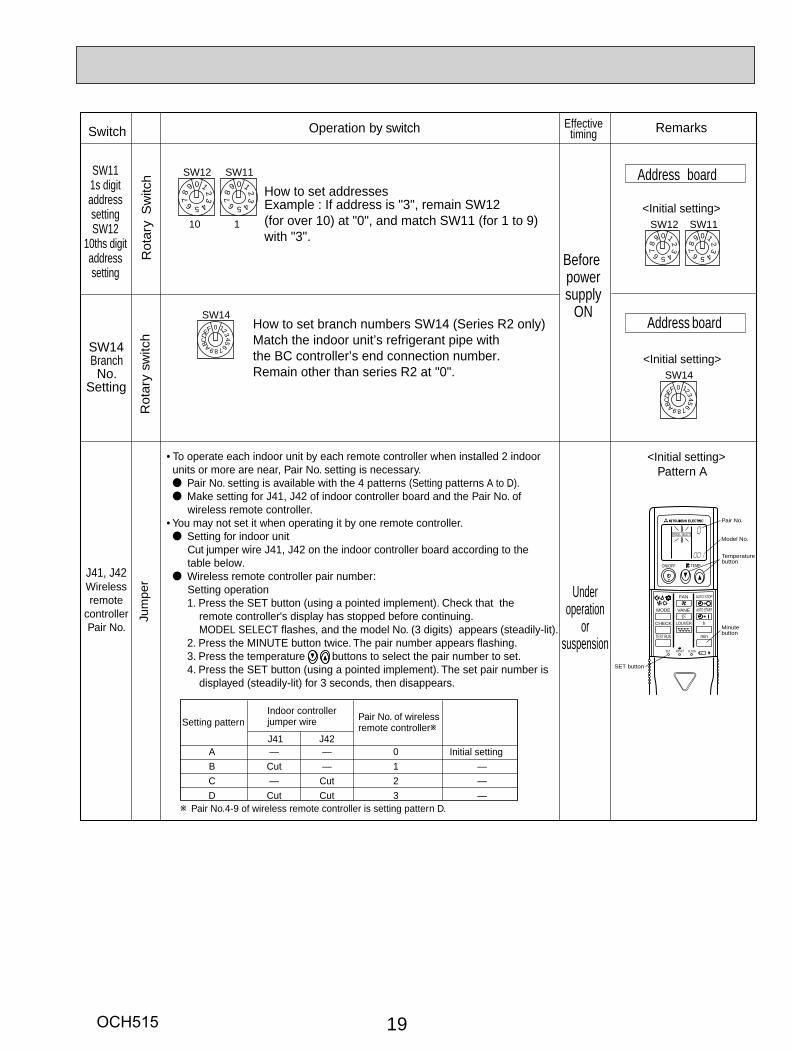
J41, J42Wirelessremote
controllerPair No.
Jum
per
<Initial setting>Pattern A
Setting pattern
J41 J42
Indoor controller jumper wire Pair No. of wireless
remote controller
Initial settingAB
DC
—Cut
Cut—
——
CutCut
01
32
—
——
Pair No.4-9 of wireless remote controller is setting pattern D.
ON/OFF TEMP
FAN
VANEMODE
CHECK LOUVER
TEST RUN
AUTO STOP
AUTO START
h
min
RESETSET CLOCK
MODEL SELECTModel No.
Temperaturebutton
SET button
Pair No.
Minutebutton
• To operate each indoor unit by each remote controller when installed 2 indoor units or more are near, Pair No. setting is necessary.
Pair No. setting is available with the 4 patterns (Setting patterns A to D)..Make setting for J41, J42 of indoor controller board and the Pair No. of
wireless remote controller.• You may not set it when operating it by one remote controller.
Setting for indoor unitCut jumper wire J41, J42 on the indoor controller board according to the
table below.Wireless remote controller pair number:
Setting operation1. Press the SET button (using a pointed implement). Check that the remote controller's display has stopped before continuing.
MODEL SELECT flashes, and the model No. (3 digits) appears (steadily-lit).2. Press the MINUTE button twice. The pair number appears flashing.3. Press the temperature buttons to select the pair number to set.4. Press the SET button (using a pointed implement). The set pair number is displayed (steadily-lit) for 3 seconds, then disappears.
Operation by switchSwitch Remarks
Underoperation
orsuspension
Effectivetiming
0
5
9
4
8 37
2
6
1SW12
10
0
5
9
4
8 37
2
6
1SW11
1
0
8
F
7
E6
D 5C
4
B
3
A
2
9
1
SW14
0
5
9
4
8 37
2
6
1SW12
0
5
9
4
8 37
2
6
1SW11
0
8
F
7
E6
D 5C
4
B
3
A
2
9
1
SW14
Address board
Address board
<Initial setting>
<Initial setting>
SW111s digitaddresssettingSW12
10ths digitaddresssetting
Rot
ary
switc
h
SW14BranchNo.
Setting
Rot
ary
Sw
itch
How to set addressesExample : If address is "3", remain SW12(for over 10) at "0", and match SW11 (for 1 to 9)with "3".
How to set branch numbers SW14 (Series R2 only)Match the indoor unit’s refrigerant pipe with the BC controller’s end connection number.Remain other than series R2 at "0".
Beforepowersupply
ON
OCH515
20
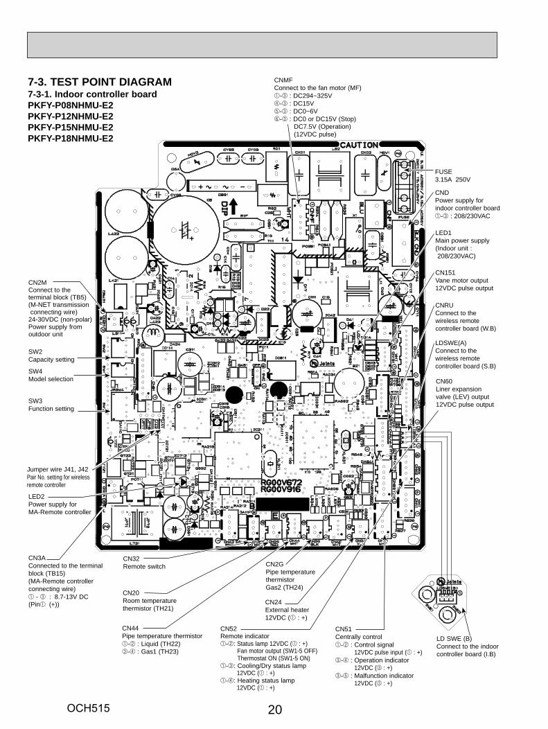
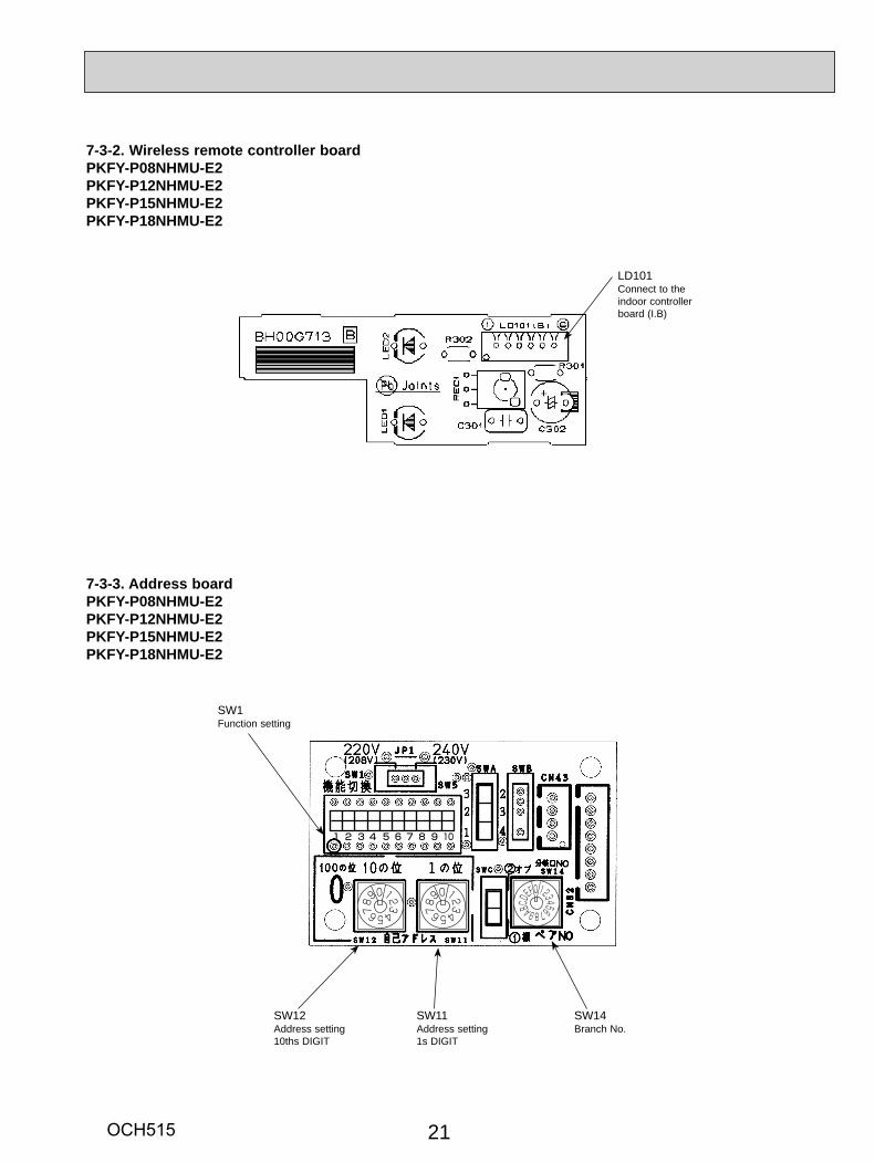
7-3. TEST POINT DIAGRAM7-3-1. Indoor controller board PKFY-P08NHMU-E2PKFY-P12NHMU-E2PKFY-P15NHMU-E2PKFY-P18NHMU-E2
CN3AConnected to the terminal block (TB15)(MA-Remote controller connecting wire)1 - 3 : 8.7-13V DC (Pin1 (+))
CN44Pipe temperature thermistor1-2 : Liquid (TH22)3-4 : Gas1 (TH23)
SW4Model selection
CNDPower supply for indoor controller board1-3 : 208/230VAC
SW2Capacity setting
LED1Main power supply(Indoor unit : 208/230VAC)
CN20Room temperature thermistor (TH21)
LED2Power supply forMA-Remote controller
CN32Remote switch
Jumper wire J41, J42Pair No. setting for wireless remote controller
LDSWE(A)Connect to the wireless remote controller board (S.B)
CN2MConnect to the terminal block (TB5) (M-NET transmission connecting wire)24-30VDC (non-polar)Power supply from outdoor unit
SW3Function setting
CN2GPipe temperature thermistorGas2 (TH24)
CN24External heater12VDC (1 : +)
CN51Centrally control1-2 : Control signal
12VDC pulse input (1 : +)3-4 : Operation indicator
12VDC (3 : +)3-5 : Malfunction indicator
12VDC (3 : +)
CN60Liner expansionvalve (LEV) output12VDC pulse output
CNRUConnect to the wireless remote controller board (W.B)
CN151Vane motor output12VDC pulse output
FUSE3.15A 250V
CNMFConnect to the fan motor (MF)1-3 : DC294~325V4-3 : DC15V5-3 : DC0~6V6-3 : DC0 or DC15V (Stop) DC7.5V (Operation) (12VDC pulse)
LD SWE (B)Connect to the indoor controller board (I.B)
CN52Remote indicator1-2: Status lamp 12VDC (1 : +) Fan motor output (SW1-5 OFF) Thermostat ON (SW1-5 ON)1-3: Cooling/Dry status lamp
12VDC (1 : +)1-4: Heating status lamp
12VDC (1 : +)
OCH515
21
1 2 3 4 5 6 7 8 9 10
123456789
0 123456789
0 123456789ABCD
EF0
7-3-3. Address boardPKFY-P08NHMU-E2PKFY-P12NHMU-E2PKFY-P15NHMU-E2PKFY-P18NHMU-E2
SW1Function setting
SW12Address setting10ths DIGIT
SW11Address setting1s DIGIT
7-3-2. Wireless remote controller boardPKFY-P08NHMU-E2PKFY-P12NHMU-E2PKFY-P15NHMU-E2PKFY-P18NHMU-E2
LD101Connect to the indoor controller board (I.B)
SW14Branch No.
OCH515
PHOTOS & ILLUSTRATIONSOPERATION PROCEDURE
22
Push
Push
Down
Be carefulnot to damage the airflow adjustmentplate with thescrew driver.
Corner hole
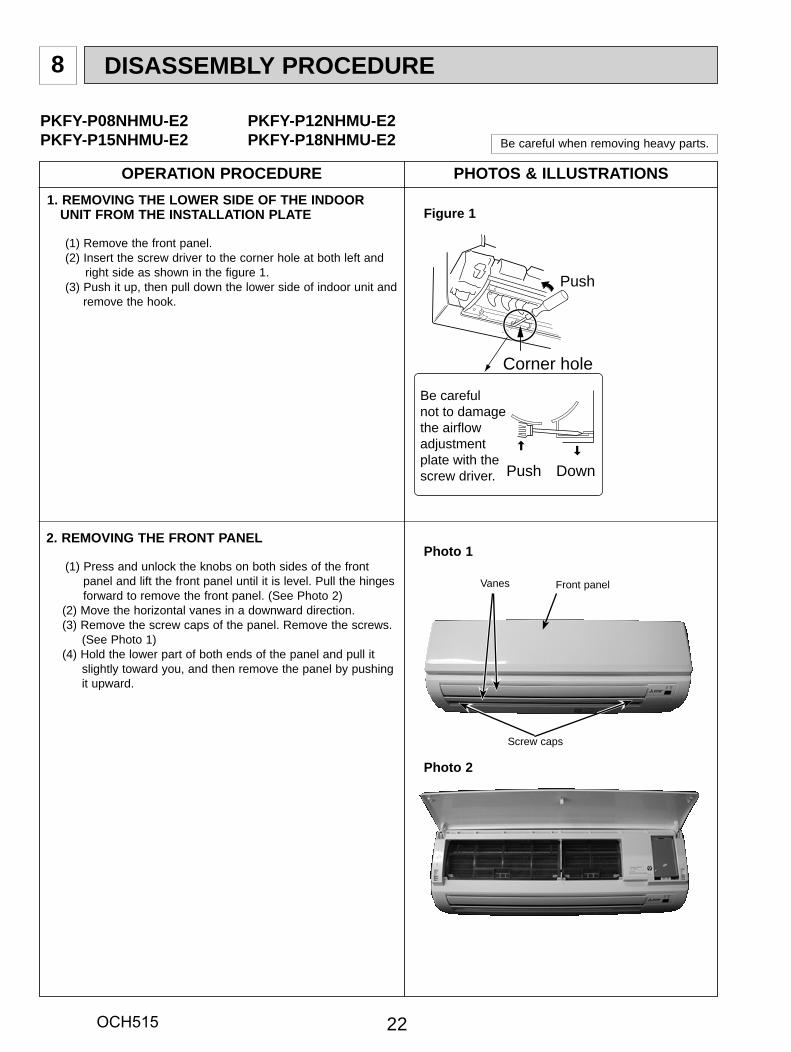
DISASSEMBLY PROCEDURE8
1. REMOVING THE LOWER SIDE OF THE INDOOR UNIT FROM THE INSTALLATION PLATE
(1) Remove the front panel.(2) Insert the screw driver to the corner hole at both left and
right side as shown in the figure 1.(3) Push it up, then pull down the lower side of indoor unit and remove the hook.
PKFY-P08NHMU-E2 PKFY-P12NHMU-E2PKFY-P15NHMU-E2 PKFY-P18NHMU-E2 Be careful when removing heavy parts.
Figure 1
2. REMOVING THE FRONT PANEL
(1) Press and unlock the knobs on both sides of the front panel and lift the front panel until it is level. Pull the hinges forward to remove the front panel. (See Photo 2)(2) Move the horizontal vanes in a downward direction.(3) Remove the screw caps of the panel. Remove the screws. (See Photo 1)(4) Hold the lower part of both ends of the panel and pull it
slightly toward you, and then remove the panel by pushing it upward.
Photo 1
Front panel
Screw caps
Vanes
Photo 2
OCH515
PHOTOSOPERATION PROCEDURE
2323
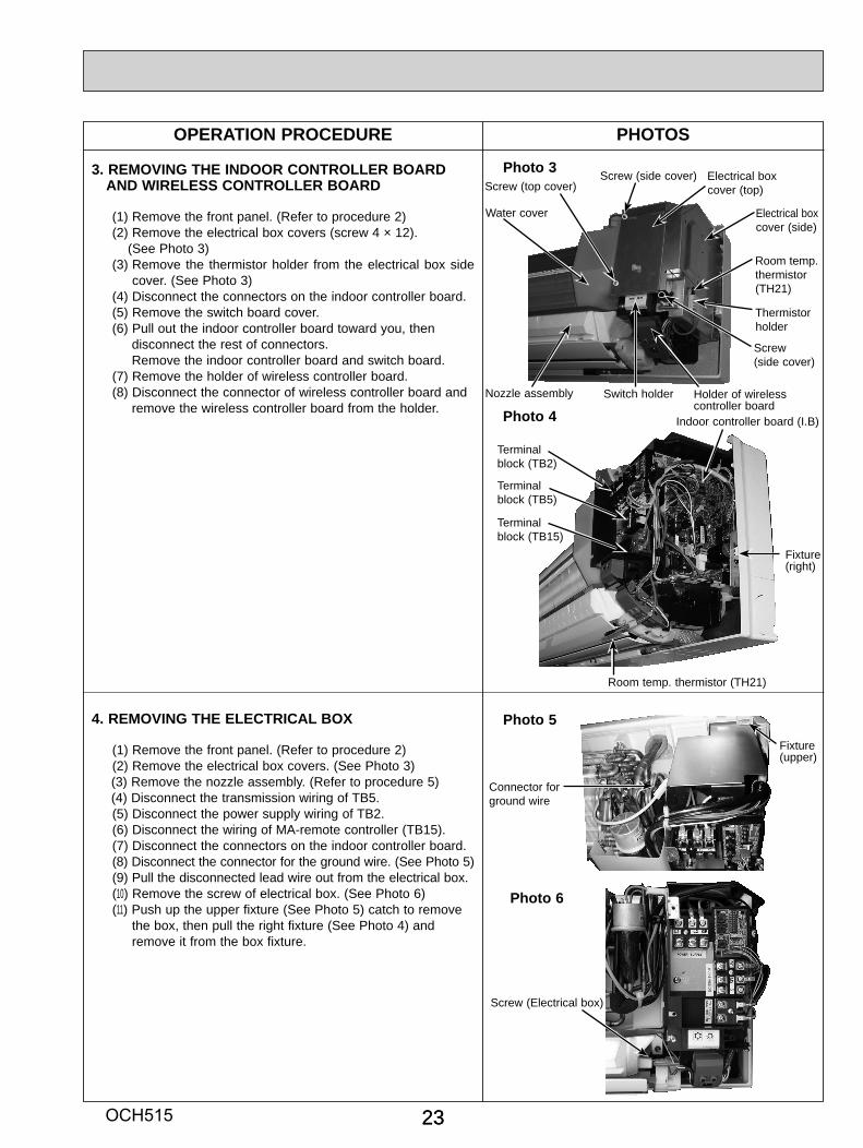
Photo 3
Indoor controller board (I.B)
4. REMOVING THE ELECTRICAL BOX
(1) Remove the front panel. (Refer to procedure 2)(2) Remove the electrical box covers. (See Photo 3)(3) Remove the nozzle assembly. (Refer to procedure 5)(4) Disconnect the transmission wiring of TB5.(5) Disconnect the power supply wiring of TB2.(6) Disconnect the wiring of MA-remote controller (TB15).(7) Disconnect the connectors on the indoor controller board.(8) Disconnect the connector for the ground wire. (See Photo 5)(9) Pull the disconnected lead wire out from the electrical box.(10) Remove the screw of electrical box. (See Photo 6)(11) Push up the upper fixture (See Photo 5) catch to remove
the box, then pull the right fixture (See Photo 4) and remove it from the box fixture.
Fixture (upper)
Terminalblock (TB2)
Photo 4
Photo 5
Fixture(right)
Connector forground wire
Photo 6
Screw (Electrical box)
Room temp. thermistor (TH21)
Fixture(right)
Terminalblock (TB5)
Terminalblock (TB15)
3. REMOVING THE INDOOR CONTROLLER BOARD AND WIRELESS CONTROLLER BOARD
(1) Remove the front panel. (Refer to procedure 2)(2) Remove the electrical box covers (screw 4 × 12). (See Photo 3)(3) Remove the thermistor holder from the electrical box side
cover. (See Photo 3)(4) Disconnect the connectors on the indoor controller board.(5) Remove the switch board cover.(6) Pull out the indoor controller board toward you, then disconnect the rest of connectors. Remove the indoor controller board and switch board.(7) Remove the holder of wireless controller board.(8) Disconnect the connector of wireless controller board and remove the wireless controller board from the holder.
Electrical box cover (top)
Electrical box cover (side)
Screw (side cover)
Holder of wirelesscontroller board
Screw(side cover)
Switch holderNozzle assembly
Screw (top cover)
Room temp. thermistor (TH21)
Thermistor holder
Water cover
OCH515
PHOTOSOPERATION PROCEDURE
24
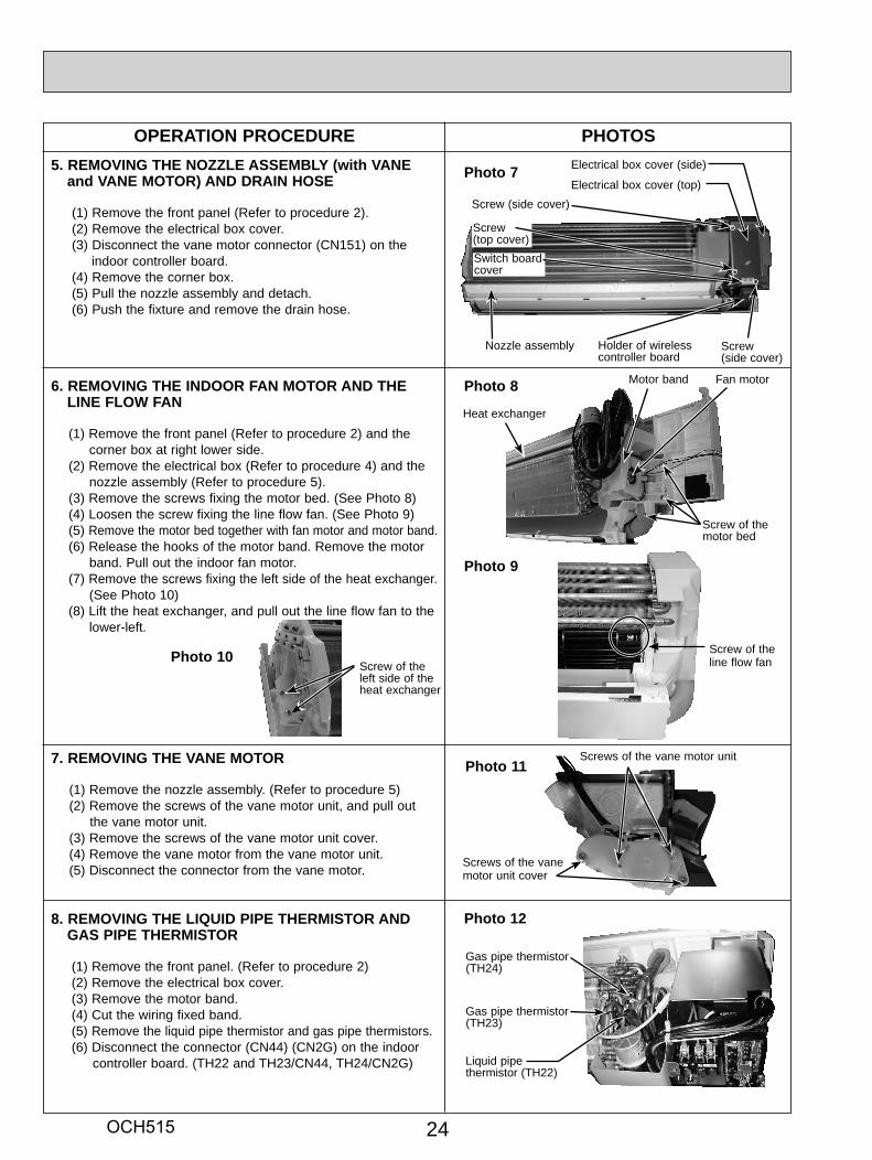
5. REMOVING THE NOZZLE ASSEMBLY (with VANE and VANE MOTOR) AND DRAIN HOSE
(1) Remove the front panel (Refer to procedure 2).(2) Remove the electrical box cover.(3) Disconnect the vane motor connector (CN151) on the indoor controller board.(4) Remove the corner box.(5) Pull the nozzle assembly and detach.(6) Push the fixture and remove the drain hose.
6. REMOVING THE INDOOR FAN MOTOR AND THE LINE FLOW FAN
(1) Remove the front panel (Refer to procedure 2) and the corner box at right lower side.
(2) Remove the electrical box (Refer to procedure 4) and the nozzle assembly (Refer to procedure 5).
(3) Remove the screws fixing the motor bed. (See Photo 8)(4) Loosen the screw fixing the line flow fan. (See Photo 9)(5) Remove the motor bed together with fan motor and motor band.(6) Release the hooks of the motor band. Remove the motor
band. Pull out the indoor fan motor.(7) Remove the screws fixing the left side of the heat exchanger. (See Photo 10)(8) Lift the heat exchanger, and pull out the line flow fan to the
lower-left.
Photo 8
Photo 9
7. REMOVING THE VANE MOTOR
(1) Remove the nozzle assembly. (Refer to procedure 5)(2) Remove the screws of the vane motor unit, and pull out
the vane motor unit.(3) Remove the screws of the vane motor unit cover.(4) Remove the vane motor from the vane motor unit.(5) Disconnect the connector from the vane motor.
8. REMOVING THE LIQUID PIPE THERMISTOR AND GAS PIPE THERMISTOR
(1) Remove the front panel. (Refer to procedure 2)(2) Remove the electrical box cover.(3) Remove the motor band.(4) Cut the wiring fixed band.(5) Remove the liquid pipe thermistor and gas pipe thermistors.(6) Disconnect the connector (CN44) (CN2G) on the indoor controller board. (TH22 and TH23/CN44, TH24/CN2G)
Photo 12
Gas pipe thermistor (TH24)
Liquid pipe thermistor (TH22)
Photo 7
Screw of the line flow fanPhoto 10
Screw of the left side of the heat exchanger
Gas pipe thermistor (TH23)
Electrical box cover (top)
Electrical box cover (side)
Screw (side cover)
Screw (top cover)Switch board cover
Holder of wirelesscontroller board
Nozzle assembly
Screws of the vane motor unit
Screws of the vane motor unit cover
Photo 11
Screw(side cover)
Screw of the motor bed
Heat exchanger
Fan motorMotor band
OCH515
PHOTOSOPERATION PROCEDURE
25
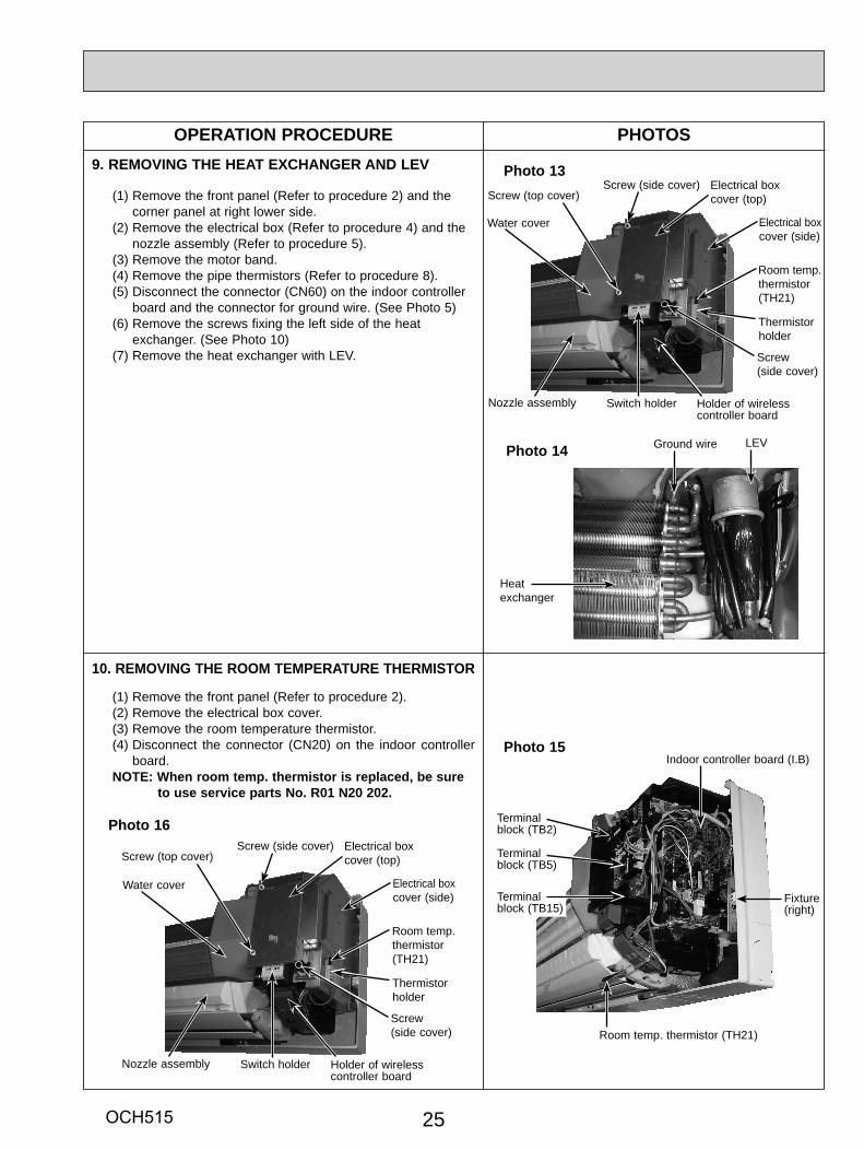
9. REMOVING THE HEAT EXCHANGER AND LEV
(1) Remove the front panel (Refer to procedure 2) and the corner panel at right lower side.
(2) Remove the electrical box (Refer to procedure 4) and the nozzle assembly (Refer to procedure 5).
(3) Remove the motor band.(4) Remove the pipe thermistors (Refer to procedure 8).(5) Disconnect the connector (CN60) on the indoor controller
board and the connector for ground wire. (See Photo 5)(6) Remove the screws fixing the left side of the heat
exchanger. (See Photo 10)(7) Remove the heat exchanger with LEV.
10. REMOVING THE ROOM TEMPERATURE THERMISTOR
(1) Remove the front panel (Refer to procedure 2).(2) Remove the electrical box cover.(3) Remove the room temperature thermistor.(4) Disconnect the connector (CN20) on the indoor controller
board.NOTE: When room temp. thermistor is replaced, be sure
to use service parts No. R01 N20 202.
Photo 13
Photo 15Indoor controller board (I.B)
Terminalblock (TB2)
Fixture(right)
Room temp. thermistor (TH21)
Fixture(right)
Terminalblock (TB5)
Terminalblock (TB15)
Photo 16
Photo 14
Heatexchanger
LEVGround wire
Electrical box cover (top)
Electrical box cover (side)
Screw (side cover)
Holder of wirelesscontroller board
Screw(side cover)
Switch holderNozzle assembly
Screw (top cover)
Room temp. thermistor (TH21)
Thermistor holder
Electrical box cover (top)
Electrical box cover (side)
Screw (side cover)
Holder of wirelesscontroller board
Screw(side cover)
Switch holderNozzle assembly
Screw (top cover)
Room temp. thermistor (TH21)
Thermistor holder
Water cover
Water cover
OCH515

Copyright 2012 MITSUBISHI ELECTRIC CORPORATIONDistributed in Apr. 2012 No. OCH515Made in Japan
New publication, effective Apr. 2012Specifications are subject to change without notice.
HEAD OFFICE : TOKYO BLDG., 2-7-3, MARUNOUCHI, CHIYODA-KU TOKYO 100-8310, JAPAN
TM


![3. SYSTEM CONTROLLER 3-2. Centralized Controller [AE-200A ...meus1.mylinkdrive.com/files/Eng_Manual_Sect_AE200A_AE-50A.pdf · 3-2. Centralized Controller [AE-200A/AE-50A] ... "Interchange](https://static.fdocuments.in/doc/165x107/5b3874197f8b9ab9068d4c6d/3-system-controller-3-2-centralized-controller-ae-200a-meus1-3-2-centralized.jpg)