Nitrato NO3
72
NO Orion 9307, Orion 9707 ionplus ® Orion Nitrate Electrode INSTRUCTION MANUAL - 3 Analyze • Detect • Measure • Control ™
-
Upload
drakenhaven -
Category
Documents
-
view
66 -
download
4
Transcript of Nitrato NO3

NOOrion 9307, Orion 9707 ionplus®
Orion NitrateElectrode
INSTRUCTION MANUAL
-3
Analyze • Detect • Measure • Control™

AQUAfast, Cahn, EZ Flash, Ionalyzer, ionplus, KNIpHE, No Cal, ORION, perpHect, PerpHecT, PerpHecTion, pHISA, pHix, pHuture, Pure Water, Sage, Sensing the Future, SensorLink, ROSS Ultra, Sure-Flow, TEA Analyzer, Titrator PLUS, TURBO2 and Wine Master are registered trademarks of Thermo Electron Corporation.
1-888-pHAX-ION, A+, All in One, Aplus, AQUAsnap, AssuredAccuracy, AUTO-BAR, AUTO-CAL, AUTO DISPENSER, Auto-ID, AUTO-LOG, AUTO-READ, AUTO-STIR, Auto-Test, BOD AutoEZ, Cable-Free, CERTI-CAL, CISA, DataCOLLECT, DataPLUS, digital LogR, DirectCal, DuraProbe, Environmental Product Authority, Extra Easy/Extra Value, FAST QC, Flash Titration, Flash Titrator, GAP, GLPcal, GLPcheck, GLPdoc, ISEasy, KAP, LabConnect, LogR, Low Maintenance Triode, Minimum Stir Requirement, MSR, NISS, One-Touch, One-Touch Calibration, One-Touch Measurement, Optimum Results, Pentrode, pHuture MMS, pHuture Pentrode, pHuture Quatrode, pHuture Triode, Quatrode, QuiKcheK, rf link, ROSS, ROSS Resolution, SAOB, Smart CheK, Stacked, Stat Face, The Enhanced Lab, ThermaSense, Triode, TRIUMpH, Unbreakable pH, Universal Access are trademarks of Thermo.
Guaranteed Success and The Technical Edge are service marks of Thermo.
PerpHecT meters are protected by U.S. patent 6,168,707.
PerpHecT ROSS are protected by U.S. patent 6,168,707.
ORION Series A meters and 900A printer are protected by U.S. patents 5,108,578, 5,198,093 and German patents D334,208 and D346,753.
Sure-Flow electrodes are protected by European Patent 278,979 and Canadian Patent 1,286,720.
ionplus electrodes and Optimum Results solutions are protected by US Patent 5,830,338.
ROSS Ultra electrodes have patents pending.
ORION ORP Standard is protected by US Patent 6,350,367.
ORION Series A conductivity meters are protected by US Patent 5,872,454.
© Copyright 2003, Thermo Electron Corporation. All rights reserved. Question everything, and Analyze.Detect.Measure.Control are trademarks of Thermo Electron Corporation.
The specifications, descriptions, drawings, ordering information and part numbers within this document are subject to change without notice.
This publication supersedes all previous publications on this subject.

GENERAL INFORMATION 1Introduction 1Required Equipment 2Required Solutions 3
BEFORE USING THE ELECTRODE 5Electrode Assembly and Preparation 5
Orion 9307 Nitrate Half Cell Electrode 5Orion 90-02 Double Junction Reference Electrode 5Orion 9707 ionplus® Nitrate Combination Electrode 6
Checking Electrode Operation (Slope) 10
Recommendations for Optimum Results 13Units of Measurement 13Sample Requirements 13Important ISE Measurement Techniques 14
Roadway to ionplus® Success! 16Guide to measuring techniques 16
MEASUREMENT PROCEDURES 18Direct Measurement 18Small Volume Direct Measurement 24Low-Level Measurements By Direct Measurement 29Known Addition 34
ELECTRODE STORAGE 44
TROUBLESHOOTING 46Troubleshooting Checklist 46Troubleshooting Guide 50Assistance 53
ELECTRODE CHARACTERISTICS 54Electrode Response 54Limits of Detection 54Reproducibility 54Temperature Effects 54Interferences 56Electrode Life 57Theory of Operation 59
WARRANTY 63ORDERING INFORMATION 67SPECIFICATIONS 68
TABLE OF CONTENTS

1
GENERAL INFORMATION
Introduction
The Orion 9307 and Orion 9707 ionplus® Nitrate Electrodes measurenitrate in aqueous solutions simply, accurately, and economically.
The Orion 9707 ionplus® Nitrate Electrode offers additional benefitsfrom its Sure-Flow® combination reference design. With thiselectrode, a separate reference electrode is unnecessary, making itconvenient to use with small sample volumes. The free-flowing Sure-Flow junction assures stable, drift-free potentials. Whenmeasuring dirty samples that would clog conventional electrodejunctions, the Sure-Flow junction can be cleaned by pressing theelectrode cap.
General analytical procedures, required solutions, electrodecharacteristics, and electrode theory are discussed in this manual.Operator instructions for Orion meters are outlined in the individualmeter’s instruction manual.
Consult Orion’s Technical Service Chemists for assistance and troubleshooting advice. Please refer to Troubleshooting forinformation on contacting Orion.

2
Required Equipment
MeterISE meters, such as Orion EA 940, 920A, 720A, 710A, or 290A,offering direct concentration readout for specific ions are the easiestto use. If unavailable, use a pH/mV meter with readability to 0.1 mV,such as Orion 420A, 520A, or 525A.
Reference Electrode Orion No.
For use with Orion 9307:Orion 90-02 Double Junction Reference Electrode 900200
For use with Orion 9707:No separate reference electrode required NA
ionplus® Stirring Accessory or Stir Bars, and Magnetic Stirrer Stir bar or ionplus® stirring accessory, Orion 900060 which slidesover the electrode body, to mix solution. Micro stir bars arerecommended for small volume measurements.
Graph Paper 4 cycle semi-logarithmic paper for preparing calibration curves (for use with digital pH/mV laboratory meters).

3
Required Solutions
Distilled or Deionized WaterTo prepare all solutions and standards.
Reference Electrode Filling SolutionRequired for a complete measuring system.
Filling Solution Orion No.
For Orion 9707 & Outer chamber of Orion 90-02:Optimum Results™ F Filling Solution 900046
NOTE: Do not use the outer filling solution shipped with the reference electrode.
For Orion 90-02:Inner Chamber Filling Solution 900002
Nitrate Stock Calibration StandardsTo prepare daily calibration solutions.
Standards Orion No.
0.1 M Nitrate Concentration Standard 920706
1000 ppm as N Standard 920707
100 ppm as N Standard 930707
Ionic Strength Adjustor (ISA) Orion 930711To adjust ionic strength of samples and standards.
Nitrate Interference Suppressor Solution Orion 930710For removal of a variety of interfering anions, including chloride ion,present in samples such as drinking water, wastewaters, and soils.See Interferences.
Preservative Solution Customer PreparedPrepare a 1 M boric acid preservative solution by dissolving 6.2 greagent-grade boric acid in 100 mL boiling water. Let cool. Add 1 mLpreservative solution to 100 mL of all standards and samples to prevent biological degradation of the solutions.

4

5
BEFORE USING THE ELECTRODE
Electrode Assembly and Preparation
Orion 9307 Nitrate Half Cell Electrode:
Remove the sensing module from the vial. Make sure the rubberelectrode washer on the sensing module is in place. See Figure 1.Screw the sensing module into the electrode body until finger tight. Toensure electrical continuity, shake down the electrode like a clinicalthermometer. Rinse the nitrate electrode with distilled water, then soakin Nitrate Standard, 100 ppm (or 10 -2 M) for 1 to 2 hours prior toinitial use. Do not immerse the electrode past the rubber electrodewasher. See Figure 1.
Orion 90-02 Double Junction Reference Electrode:
Required for use with Orion 9307 Nitrate Half Cell Electrode. Noassembly is required. Fill the reference electrode according toinstructions in the reference electrode instruction manual, using Orion900002 Filling Solution in the inner chamber. Use Optimum Results F,Orion 900046, instead of the Outer Chamber Filling Solution providedwith the electrode. Do not use the outer chamber filling solutionshipped with the 90-02 reference electrode because it will interferewith your nitrate measurements.
Figure 1Orion 9307 Electrode Assembly
electrode body
washer
sensing module
sensing membrane
6
outer body sleeve
cap
spring
inner stem
reference pellet
fill hole
sensing module
sensing membrane
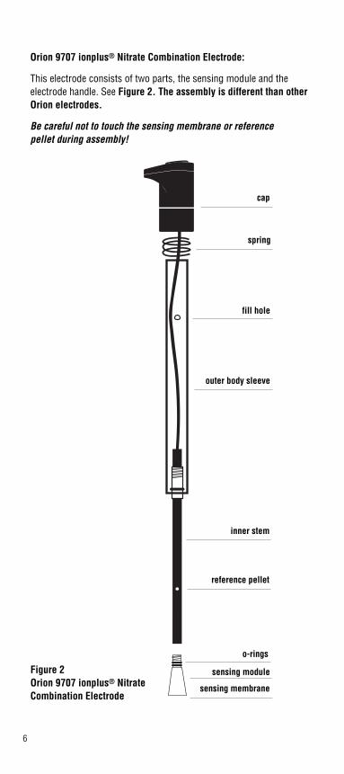
Orion 9707 ionplus® Nitrate Combination Electrode:
This electrode consists of two parts, the sensing module and theelectrode handle. See Figure 2. The assembly is different than otherOrion electrodes.
Be careful not to touch the sensing membrane or reference pellet during assembly!
o-rings
Figure 2Orion 9707 ionplus® Nitrate Combination Electrode
7
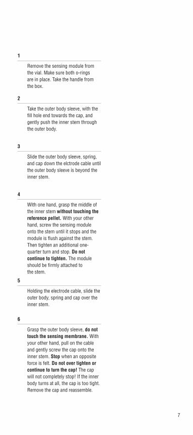
6
Grasp the outer body sleeve, do nottouch the sensing membrane. Withyour other hand, pull on the cableand gently screw the cap onto theinner stem. Stop when an oppositeforce is felt. Do not over tighten orcontinue to turn the cap! The capwill not completely stop! If the innerbody turns at all, the cap is too tight.Remove the cap and reassemble.
2
Take the outer body sleeve, with thefill hole end towards the cap, andgently push the inner stem throughthe outer body.
3
Slide the outer body sleeve, spring,and cap down the elctrode cable untilthe outer body sleeve is beyond theinner stem.
4
With one hand, grasp the middle ofthe inner stem without touching thereference pellet. With your otherhand, screw the sensing moduleonto the stem until it stops and themodule is flush against the stem.Then tighten an additional one-quarter turn and stop. Do notcontinue to tighten. The moduleshould be firmly attached to the stem.
1
Remove the sensing module fromthe vial. Make sure both o-rings are in place. Take the handle fromthe box.
5
Holding the electrode cable, slide theouter body, spring and cap over theinner stem.

8
7
Hold the electrode with one hand.Press on the top of the cap with yourthumb to make sure the electrodehas a smooth flushing motion andreseats back onto the module.
8
Fill the outer body withOptimum Results F filling solution,Orion 900046, to approximately1⁄4 full.
9
Press cap to flush out the solution.Release cap and ensure that theouter body sleeve returns to its original position.
10
Refill the electrode with OptimumResults F filling solution until thefluid level is just below the fill hole.

9
Electrode reference filling solution should be added each day beforeuse. The filling solution should be no lower than 1 inch from the fill holeand must be above the reference pellet. The filling solution level shouldalways remain 1 inch above the sample level to ensure proper flow rate.Rinse the nitrate electrode with distilled water, then soak in NitrateStandard, 100 ppm (or 10 -2 M) for 1 to 2 hours prior to initial use.
11
To ensure electrical continuity, graspthe outer body and cap and shakethe sensing module end firmly.Check to make sure the membranesurface is dark and homogeneouswith no bubbles on the inner surface.

10
Checking Electrode Operation (Slope)
Use these general instructions to check electrode operation. Seeindividual meter instruction manuals for more specific information.
This procedure measures electrode slope. Slope is defined as thechange in millivolts observed with every tenfold (decade) change inconcentration. Obtaining the slope value provides the best means forchecking electrode operation.
1
If electrode(s) has been stored dry,prepare the electrode(s) as describedunder the section entitled ElectrodeAssembly and Preparation.
2
Connect electrode(s) to the meter as described in the meterinstruction manual.
3
Select either 0.1 M or 1000 ppmnitrate standard.
OR 1000 ppmN
0.1 M

11
4
Place 100 mL distilled water into a150 mL beaker. Add 2 mL ISA, Orion930711. Stir thoroughly.
5
Set the meter to the mV mode.
6
Rinse electrode(s) with distilledwater, blot dry, and place in the solution prepared in step 4 above.
7
Pipet 1.0 mL of the standard into thebeaker. Stir thoroughly.
ISA
mV
1.0 mL

12
8
When a stable reading is displayed, record the electrodepotential in millivolts.
9
Pipet 10.0 mL of the same standardinto the same beaker. Stir thoroughly.
10
When a stable reading is displayed(within 4 to 5 minutes), record theelectrode potential in millivolts.
11
The difference between the first andsecond potential reading is defined asthe slope of the electrode. Thedifference should be in the range of -54 to -60 mV/decade when the solutiontemperature is 25 ± 5°C. If the slope isnot within this range, resoak theelectrode as described under thesection entitled Electrode Assemblyand Preparation. For othertroubleshooting techniques refer to theTroubleshooting section.
mV
10.0 mL
mV

13
Recommendations for Optimum Results
Units of Measurement
Measure nitrate in units of moles per liter, parts per million as nitrate,parts per million as nitrogen or any other convenient unit (see Table 1).
Table 1Concentration Unit Conversion Factors
moles ppm ppmper liter as NO3
- as N
10-4 6.20 1.40
10-3 62.0 14.0
10-2 620 140
Sample Requirements
Samples must be aqueous and must not contain organic solvents.Consult Orion’s Technical Service Chemists for using the electrode inspecific applications.
Sample temperature must be less than 40°C, with samples andstandards all at the same temperature. At the 14 ppm as N or 10-3 M NO3
- level, a 1°C difference in temperature produces about a1.5% error. For highly accurate results, use a water bath to controltemperature variances.
Interferences should be absent. See section entitled Interferences fora list of possible interferences. If interferences are present in thesample and cannot be removed, use Nitrate Interference SuppressorSolution, Orion 930710, instead of ISA solution.

14
Important ISE Measurement Techniques
• Stir all standards and samples at a uniform rate during measurement. Magnetic stirrers may generate sufficient heat to change solution temperature. Place a piece of insulating material such as cork, cardboard or styrofoam between the stir plate and sample beaker.
• Always use fresh standards for calibration.
• Always rinse electrode(s) with distilled water thoroughly between measurements. Shake electrode after rinsing to prevent solution carryover, then blot dry. Do not wipe or rub the sensing membrane, as you may contaminate and damage the surface.
• Allow all standards and samples to come to room temperature for precise measurements.
• After immersion in solution, check the nitrate electrode for any air bubbles on the membrane surface. Remove air bubbles at the electrode surface by gently tapping the electrode.
• The Orion 9307 Nitrate Half-Cell Electrode should be submerged approximately half the length of the nitrate module. DO NOT submerge the nitrate electrode above the rubber electrode washer.Submerge the reference electrode to the same depth as the nitrate electrode.
• Nitrate solutions are a culture medium for bacteria and algae. Dilute samples and standards cannot be kept unless they are treated to inhibit biological growth. Preservation Solution should thus be added to samples when they are collected (1 mL for every 100 mL of sample).
• If interferences are present, use Nitrate Interference Suppressor Solution, Orion 930710. Samples such as soils and plant tissues may have a variety of interfering ions present. See Interferences.
15
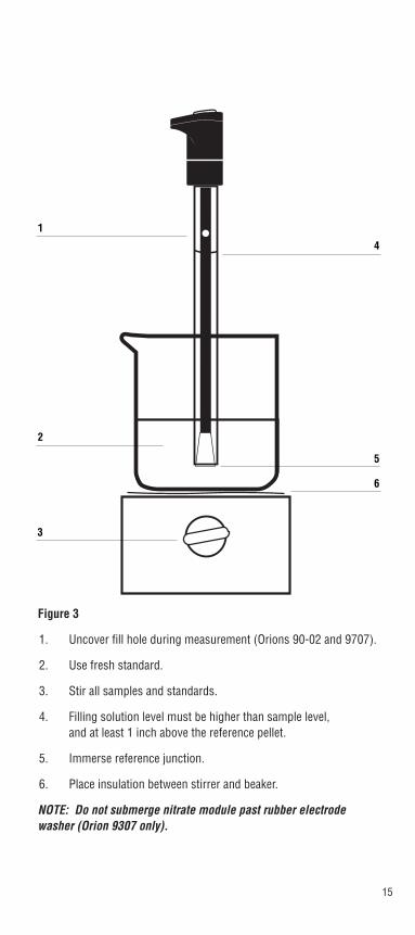
Figure 3
1. Uncover fill hole during measurement (Orions 90-02 and 9707).
2. Use fresh standard.
3. Stir all samples and standards.
4. Filling solution level must be higher than sample level, and at least 1 inch above the reference pellet.
5. Immerse reference junction.
6. Place insulation between stirrer and beaker.
NOTE: Do not submerge nitrate module past rubber electrode washer (Orion 9307 only).
1
2
3
4
5
6

16
Roadway to ionplus® Success!
Guide to measuring techniques
Direct Small Volume Low-Level KnownMeasurement Direct Measurement Addition
Measurement
Recommended 0.1 to 14000 0.1 to 14000 <1.4 ppm as N 1.4 to 14000Concentration ppm as N ppm as N ppm as NRange
Large # X X X Xof samples (Orion 9707 only)
Small sample X Xvolume (Orion 9707 only)
Reduced Xchemical usage (Orion 9707 only)
Field X X XMeasurements (Orion 9707 only)
Ionic Strength X>0.1 M
Occasional Xsampling
see page # 18 24 29 34

17
A variety of analytical techniques are available to the analyst. The besttechnique is dependent upon sample matrix. The following sectiondescribes the recommended techniques for nitrate determination.
Direct Measurement is a simple procedure for measuring a largenumber of samples. This method requires only one meter reading foreach sample. Calibration is performed with a series of standards. Theconcentration of the samples is determined by comparison to thestandards. Addition of ISA to all solutions ensures that samples andstandards have similar ionic strength, proper pH, and reduces theeffect of interfering ions. Alternatively, Nitrate Interference SuppressorSolution is specially formulated to eliminate interfering ion effects in typical sample matrices. When measuring small sample volumes or to reduce chemical usage, follow the Small Volume DirectMeasurement method, using the Orion 9707 ionplus®
Nitrate Electrode.
Low-Level Measurement is similar to Direct Measurement. Use this method when the expected sample concentration is less than 1.4 ppm as N. Using a minimum of three calibration standards compensates for the electrode’s non-linear response at lowconcentrations. This procedure describes the best means of preparinglow-level calibration standards.
Known Addition is an alternate method useful when measuring only afew samples, when samples have a high (>0.1 M) ionic strength, orhave a complicated background matrix. Refer to Theory of Operationfor an explanation of these effects. The electrodes are immersed in thesample solution and an aliquot of a nitrate standard solution is addedto the sample. From the change in potential before and after theaddition, the original sample concentration is determined. As in directcalibration, any convenient concentration unit can be used.

18
MEASUREMENT PROCEDURES
Direct Measurement
The following direct measurement procedures are recommended for “high-level” measurements, when all samples fall within theelectrode’s linear range, greater than 1.4 ppm as N or 10-4 M NO3
-. A two point calibration is sufficient, though more points can be used if desired. Using ISE meters, such as the Orion 920A, 720A, 710A, or290A, read sample concentrations directly from the meter. Refer to themeter’s instruction manual for calibration details. When using a mVmeter, prepare a calibration curve on semi-logarithmic graph paper, or a linear regression can be performed at the user’s discretion using a spreadsheet or graphing program.
For Improved Accuracy
• Bracket standard concentrations around the expected sample concentration.
• Always dilute samples and standards in a 50:1 ratio with ISA. For example, 100 mL of sample and 2 mL of ISA.
• Alternatively, Nitrate Interference Suppressor Solution can be used in a 1:1 dilution ratio. Do not use ISA when using Nitrate Interference Suppressor Solution.
• Verify this procedure by measuring a standard of known concentration as an unknown or by spiking a sample with nitrate standard.
• For high ionic strength samples, having an ionic strength of 0.1 M or greater, prepare standards with a composition similar to that of the samples, measure the samples using the known addition method, or dilute the samples.
• During calibration, measure the least concentrated standard first, and work up to the most concentrated.
• The best method for preparation of standards is serial dilution. This procedure involves preparing an initial standard that is diluted to prepare a second standard solution using volumetric glassware. The second is similarly diluted to prepare a third standard, and so on, until the desired range of standards has been prepared.
• Review section entitled Important ISE Measurement Techniques.
19
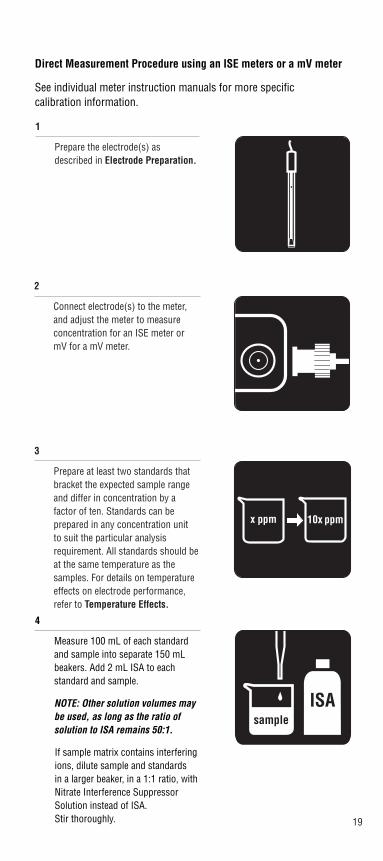
1
Prepare the electrode(s) asdescribed in Electrode Preparation.
2
Connect electrode(s) to the meter,and adjust the meter to measureconcentration for an ISE meter ormV for a mV meter.
3
Prepare at least two standards thatbracket the expected sample rangeand differ in concentration by a factor of ten. Standards can be prepared in any concentration unit to suit the particular analysisrequirement. All standards should beat the same temperature as thesamples. For details on temperatureeffects on electrode performance,refer to Temperature Effects.
x ppm 10x ppm
4
Measure 100 mL of each standardand sample into separate 150 mLbeakers. Add 2 mL ISA to each standard and sample.
NOTE: Other solution volumes maybe used, as long as the ratio ofsolution to ISA remains 50:1.
If sample matrix contains interferingions, dilute sample and standards in a larger beaker, in a 1:1 ratio, withNitrate Interference SuppressorSolution instead of ISA. Stir thoroughly.
ISAsample
Direct Measurement Procedure using an ISE meters or a mV meter
See individual meter instruction manuals for more specificcalibration information.

20
6
For an ISE meter: Rinse electrode(s)with distilled water, shake dry, andplace into the beaker with the nextstandard. Wait for a stable reading,then adjust the meter to display thevalue of the second standard, asdescribed in the meter instructionmanual.
For a mV meter: Rinse electrode(s)with distilled water, shake dry, andplace into the beaker containing the next standard. When a stablereading is displayed, record the mV value and corresponding standard concentration.
5
For an ISE meter: Rinse electrode(s)with distilled water, shake dry, andplace into the beaker containing themost dilute standard. Wait for a stable reading, calibrate the meter todisplay the value of the standard asdescribed in the meter instructionmanual.
For a mV meter: Rinse electrode(s)with distilled water, shake dry, andplace into the beaker containing themost dilute standard. When a stablereading is displayed, record the mV value and corresponding standard concentration.
DI
CAL
ENTER
21
7
Repeat step 6 for all standards,working from the least concentratedto most concentrated standard.
8
For an ISE meter: Calibrationinformation will be calculated andstored automatically.
For a mV meter: Using semi-logarithmic graph paper, prepare acalibration curve by plotting the millivolt values on the linear axis andthe standard concentration values onthe logarithmic axis. See Figure 4.

22
9
Rinse electrode(s) with distilledwater, shake dry, and place into the sample.
10
For an ISE meter: When theelectrode stabilizes, the meter will display the sample concentration.
For a mV meter: When the electrodestabilizes, the meter will display themV value for the sample. Using thecalibration curve prepared in step 8,determine the unknown sampleconcentration.
DI
RESULT
23
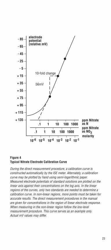
Figure 4Typical Nitrate Electrode Calibration Curve
During the direct measurement procedure, a calibration curve is constructed automatically by the ISE meter. Alternately, a calibrationcurve may be plotted by hand using semi-logarithmic paper.Measured electrode potentials of standard solutions are plotted on thelinear axis against their concentrations on the log axis. In the linearregions of the curves, only two standards are needed to determine acalibration curve. In non-linear regions, more points must be taken foraccurate results. The direct measurement procedures in the manualare given for concentrations in the region of linear electrode response.When measuring in the non-linear region follow the low-level measurement procedure. This curve serves as an example only. Actual mV values may differ.
ppm Nitrateas NO3
- 85
- 65
- 45
- 25
- 5
+ 15
+ 35
+ 55
+ 75
+ 95
+ 115
+ 135.1 1 10 100 1000
.1 1 10 100 1000
10-6 10-5 10-4 10-3 10-2 10-1
electrodepotential(relative mV)
10-fold change
56mV
ppm Nitrateas N
molarity

24
Small Volume Direct Measurement (Orion 9707 ionplus® Nitrate Electrode only)
Using the Sure-Flow reference design, the Orion 9707 ionplus® NitrateElectrode allows measurement of sample volumes as small as 5 mLwith a modified direct measurement procedure. This technique isapplicable to any sample where reduced chemical usage of standards,Nitrate Interference Suppressor, and ISA is important. This small volume measurement is well suited for field testing as the combinationreference electrode conveniently reduces equipment, set-up and sampling time. All samples should be greater than 1.4 ppm as N or 10-4 M NO3
-. As with the previously described Direct Measurementprocedure, a two point calibration is sufficient, though more pointscan be used if desired. Use a direct concentration meter (ISE meter) or a pH/mV meter with 0.1 mV resolution. The following procedurerecommends using 25 mL of sample. Smaller sample volumes can beused, as long as the final volume of solution is sufficient to cover thereference junction of the Orion 9707 ionplus® electrode. Do not allowthe sensing membrane to touch the sample container.
For Improved Accuracy
• Use Orion 9707 ionplus® Nitrate Electrode.
• Bracket standard concentrations around the expected sample concentration.
• Always dilute samples and standards in a 50:1 ratio with ISA, or in a 1:1 ratio with Nitrate Interference Suppressor.
• Verify this procedure by measuring a standard of known concentra-tion as an unknown or by spiking a sample with nitrate standard.
• For high ionic strength samples, having an ionic strength of 0.1 M or greater, prepare standards with a composition similar to that of the samples, measure the samples using the known addition method, or dilute the samples.
• During calibration, measure the least concentrated standard first, and work up to the most concentrated.
• The best method for preparation of standards is serial dilution. This procedure involves preparing an initial standard that is diluted to prepare a second standard solution using volumetric glassware. The second is similarly diluted to prepare a third standard, and so on, until the desired range of standards has been prepared.
• Review section entitled Important ISE Measurement Techniques.
25
Small Volume Direct Measurement Procedure using an ISE Meter or a mV meter and Orion 9707 ionplus® Nitrate Electrode
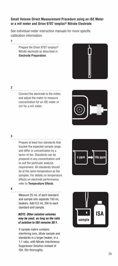
See individual meter instruction manuals for more specific calibration information.1
Prepare the Orion 9707 ionplus®
Nitrate electrode as described inElectrode Preparation.
2
Connect the electrode to the meter,and adjust the meter to measureconcentration for an ISE meter ormV for a mV meter.
3
Prepare at least two standards thatbracket the expected sample rangeand differ in concentration by a factor of ten. Standards can be prepared in any concentration unitto suit the particular analysisrequirement. All standards shouldbe at the same temperature as thesamples. For details on temperatureeffects on electrode performance,refer to Temperature Effects.
x ppm 10x ppm
4
Measure 25 mL of each standardand sample into separate 150 mLbeakers. Add 0.5 mL ISA to eachstandard and sample.
NOTE: Other solution volumesmay be used, as long as the ratioof solution to ISA remains 50:1.
If sample matrix containsinterfering ions, dilute sample and standards in a larger beaker, in a1:1 ratio, with Nitrate InterferenceSuppressor Solution instead ofISA. Stir thoroughly.
ISAsample

26
6
For an ISE meter: Rinse ionplus®
Nitrate Electrode with distilledwater, shake dry, and place into thebeaker with the next standard. Waitfor a stable reading, then adjust themeter to display the value of thesecond standard, as described inthe meter instruction manual.
For a mV meter: Rinse ionplus®
Nitrate Electrode with distilledwater, shake dry, and place into thebeaker containing the nextconcentrated standard. When astable reading is displayed, recordthe mV value and corresponding standard concentration.
5
For an ISE meter: Rinse Orion9707 ionplus® Nitrate Electrodewith distilled water, shake dry, andplace into the beaker containing themost dilute standard. Wait for astable reading, calibrate the meterto display the value of the standardas described in the meterinstruction manual.
For a mV meter: Rinse Orion 9707ionplus® Nitrate Electrode with distilled water, shake dry, and placeinto the beaker containing the most dilute standard. Wait for astable reading, record the mV valueand corresponding standard concentration.
DI
CAL
ENTER

27
7
Repeat step 6 for all standards,working from the least concentratedto most concentrated standard.
8
For an ISE meter: Calibrationinformation will be calculated andstored automatically.
For a mV meter: Using semi-logarithmic graph paper, prepare a calibration curve by plotting the millivolt values on the linear axisand the standard concentration values on the logarithmic axis. See Figure 4.

28
9
Rinse ionplus® Nitrate Electrodewith distilled water, shake dry, andplace into the sample.
10
For an ISE meter: When the electrode stabilizes, the meter will display the sample concentration.
For a mV meter: When the electrode stabilizes, the meter will display the mV value for the sample. Using the calibration curveprepared in step 8, determine theunknown sample concentration.
DI
RESULT

29
Low-Level Measurements By Direct Measurement
Use this method when measuring solutions with a nitrateconcentration of less than 1.4 ppm as N or 10-4 M NO3
-, those withinthe non-linear range of the nitrate electrode. Low-level measurementsrequire at least three standards to compensate for the electrode’snon-linearity.
For Improved Accuracy
• If some samples have low-level concentrations, and some have higher concentrations, dilute the higher concentrations down to the low-level range. The electrode’s response time at low-levels is faster when it is not exposed to high concentrations.
• The choice of calibration standard concentrations is important for obtaining the best electrode performance and most rapid analysis time. Here are some guidelines:
Ideally, calibration standard concentrations should bracket theexpected sample concentrations.
The best results are obtained when the concentration of the highestcalibration standard is ten to one hundred times the lowestcalibration standard concentration. Space additional standardsequally within the range.
If the expected sample concentrations fall within a narrow range(less than one order of magnitude), a ratio of highest to lowest standard concentration of ten should be used.
When measuring sub-ppm levels with Orion 920A, 720A, 710A, or290A, take advantage of the autoblank feature. It does not require azero standard, but can perform blank correction as long as thelowest standard concentration is in the non-linear range of theelectrode. Electrodes are very slow in the absence of a measurableconcentration and a multipoint calibration generally will be lessaccurate when “zero” is included as a standard. Standardconcentrations should be chosen such that the lowest standardvalue is larger than the blank value obtained, and the second loweststandard should be at least twice that of the lowest. See your A-Series meter instruction manual for additional information onblank correction.
When not using an ISE meter, a calibration curve can be drawn onsemi-logarithmic graph paper or the data can be processed bymeans of a spreadsheet or graphing program with a non-linearcurve fitting feature.
When using the Orion 920A, 720A, 710A or 290A, with theautoblank feature, three calibration points are sufficient. If acalibration curve is prepared manually, additional points may behelpful to facilitate drawing the curve.
• Remember to stir all standards and samples at a uniform rate.
• Review section entitled Important ISE Measurement Techniques.
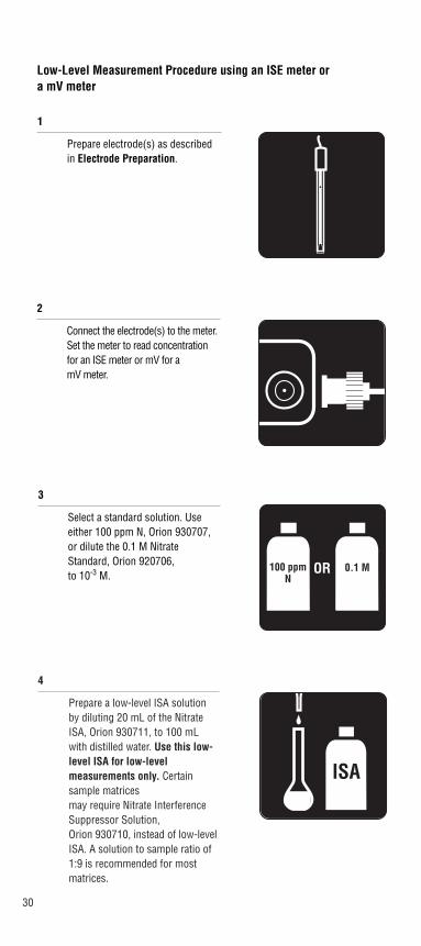
30
4
Prepare a low-level ISA solutionby diluting 20 mL of the NitrateISA, Orion 930711, to 100 mLwith distilled water. Use this low-level ISA for low-levelmeasurements only. Certainsample matrices may require Nitrate InterferenceSuppressor Solution, Orion 930710, instead of low-levelISA. A solution to sample ratio of1:9 is recommended for mostmatrices.
ISA
3
Select a standard solution. Useeither 100 ppm N, Orion 930707,or dilute the 0.1 M NitrateStandard, Orion 920706, to 10-3 M.
1
Prepare electrode(s) as describedin Electrode Preparation.
2
Connect the electrode(s) to the meter.Set the meter to read concentrationfor an ISE meter or mV for a mV meter.
OR 0.1 M100 ppmN
Low-Level Measurement Procedure using an ISE meter or a mV meter

31
5
Measure 100 mL distilled waterinto 150 mL beaker. Add 1 mLlow-level ISA.
H2O LOWISA
6
Rinse the electrode(s) with distilled water, place into beaker.Stir thoroughly.
8
For an ISE meter: Follow meterinstruction manual for detailed calibration instructions.
For a mV meter: Record stablemillivolt reading after eachincrement. On semi-logarithmicpaper, plot the concentration (logaxis) against the millivolt potential(linear axis), see Figure 4. Preparea new low-level calibration curvewith fresh standards each day.
7
Add increments of the standard tothe beaker using steps outlined inTable 2.
sample
100 ppmN

32
11
For an ISE meter: When theelectrode stabilizes, the meter will display the sample concentration.
For a mV meter: When theelectrode stabilizes, the meter will display the sample mV value.Determine the sampleconcentration corresponding to the measured potential using thelow-level calibration curve preparedin step 8.
RESULT
9
Measure 100 mL of sample into abeaker. Add 1 mL of low-level ISA.
10
Rinse the electrode(s) with distilledwater, shake dry, and place into thesample. Stir thoroughly.
sample LOWISA
33
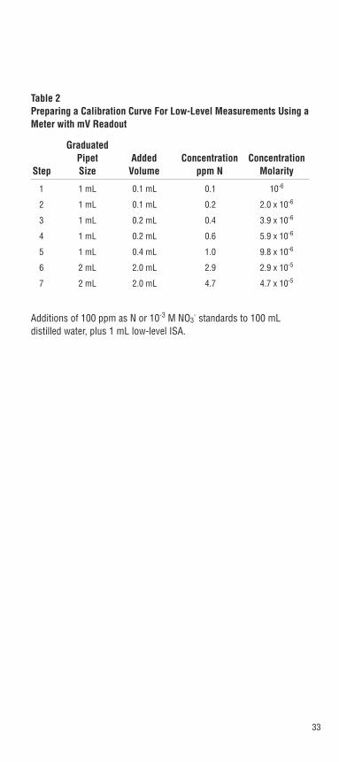
Table 2 Preparing a Calibration Curve For Low-Level Measurements Using aMeter with mV Readout
GraduatedPipet Added Concentration Concentration
Step Size Volume ppm N Molarity
1 1 mL 0.1 mL 0.1 10-6
2 1 mL 0.1 mL 0.2 2.0 x 10⁻⁶
3 1 mL 0.2 mL 0.4 3.9 x 10⁻⁶
4 1 mL 0.2 mL 0.6 5.9 x 10⁻⁶
5 1 mL 0.4 mL 1.0 9.8 x 10⁻⁶
6 2 mL 2.0 mL 2.9 2.9 x 10⁻⁵
7 2 mL 2.0 mL 4.7 4.7 x 10⁻⁵
Additions of 100 ppm as N or 10-3 M NO3- standards to 100 mL
distilled water, plus 1 mL low-level ISA.
34
Known Addition
Known addition is a convenient technique for measuring samples inthe linear response range, greater than 1.4 ppm as N or 10-4 M NO3
-,because no calibration curve is needed. Use this method to verify theresults of a direct measurement or to minimize existing matrix effects.The sample potential is measured before and after addition of a standard solution. Many meters, such as the Orion 920A and 930Ionalyzer®, have the known addition algorithms pre-programmed. Thisprogramming makes multiple standard additions to the sample,resulting in more precise results. These direct-reading meters providea great convenience. Accurate measurement requires that thefollowing conditions be met.
For Improved Accuracy
• Sample concentration should be known to within a factor of three.
• Concentration should approximately double as a result of the addition.
• With double or multiple known addition, the final addition should be 10 to 100 times the sample concentration.
• All samples and standards should be at the same temperature.
• In general, either no complexing agents or a large excess of the complexing agents may be present.
• Standard addition volume should be less than 10% of the sample volume, or standard should be pre-treated with ISA in a 50:1 ratio or a 1:1 ratio with Nitrate Interference Suppressor Solution.
• Dilute samples in a 50:1 ratio with ISA or a 1:1 ratio with Nitrate Interference Suppressor Solution before analysis.
• Review section entitled Important ISE Measurement Techniques.
35
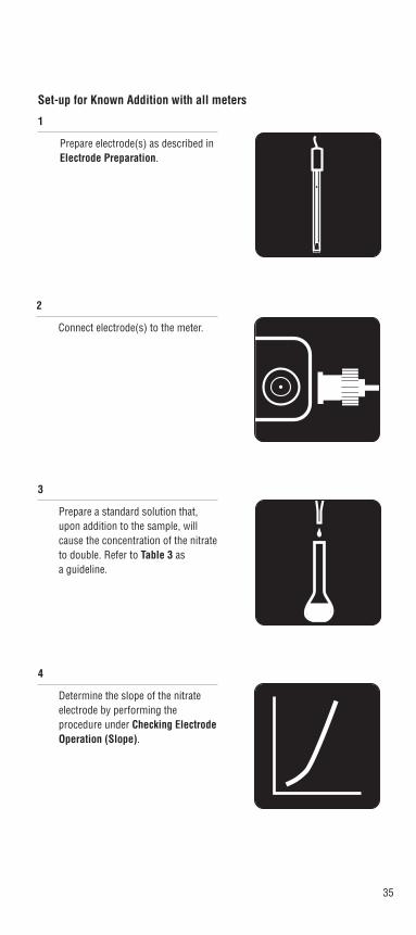
Set-up for Known Addition with all meters
1
Prepare electrode(s) as described inElectrode Preparation.
2
Connect electrode(s) to the meter.
3
Prepare a standard solution that,upon addition to the sample, willcause the concentration of the nitrateto double. Refer to Table 3 as a guideline.
4
Determine the slope of the nitrateelectrode by performing the procedure under Checking ElectrodeOperation (Slope).

36
Known Addition Measurement Procedure using an ISE meter with KA program
See individual meter instruction manuals for more specific information.
1
Set up the meter to measure in theknown addition mode.
2
Measure 50 mL of the sample into abeaker. Add 1 mL ISA or 50 mLNitrate Interference SuppressorSolution. Stir thoroughly.
KA
ISAsample

37
4
When a stable reading is displayed,program the meter as described inthe meter instruction manual.
5
Pipet the appropriate amount of thestandard solution into the beaker.Stir thoroughly.
6
When a stable reading is displayed,record the sample concentration.
3
Rinse electrode(s) with distilledwater, shake dry, and place into sample solution.
DI
sample
RESULT
38
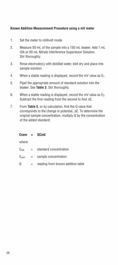
1. Set the meter to millivolt mode.
2. Measure 50 mL of the sample into a 150 mL beaker. Add 1 mLISA or 50 mL Nitrate Interference Suppressor Solution. Stir thoroughly.
3. Rinse electrode(s) with distilled water, blot dry and place intosample solution.
4. When a stable reading is displayed, record the mV value as E1.
5. Pipet the appropriate amount of standard solution into thebeaker. See Table 3. Stir thoroughly.
6. When a stable reading is displayed, record the mV value as E2.Subtract the first reading from the second to find ∆E.
7. From Table 5, or by calculation, find the Q value thatcorresponds to the change in potential, ∆E. To determine theoriginal sample concentration, multiply Q by the concentrationof the added standard:
Csam = QCstd
where:
Cstd = standard concentration
Csam = sample concentration
Q = reading from known addition table
Known Addition Measurement Procedure using a mV meter
39
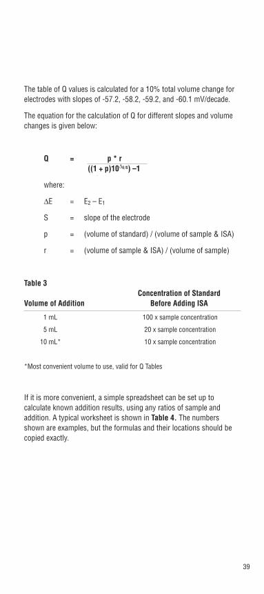
The table of Q values is calculated for a 10% total volume change forelectrodes with slopes of -57.2, -58.2, -59.2, and -60.1 mV/decade.
The equation for the calculation of Q for different slopes and volumechanges is given below:
Q = p * r ((1 + p)10∆E/S) –1
where:
∆E = E2 – E1
S = slope of the electrode
p = (volume of standard) / (volume of sample & ISA)
r = (volume of sample & ISA) / (volume of sample)
Table 3 Concentration of Standard
Volume of Addition Before Adding ISA
1 mL 100 x sample concentration
5 mL 20 x sample concentration
10 mL* 10 x sample concentration
*Most convenient volume to use, valid for Q Tables
If it is more convenient, a simple spreadsheet can be set up tocalculate known addition results, using any ratios of sample andaddition. A typical worksheet is shown in Table 4. The numbersshown are examples, but the formulas and their locations should becopied exactly.

40
Table 4Calculating known addition for nitrate samples using Lotus, Excel or Quattro Spreadsheet
A B C
1 Enter Values
2 VOL. OF SAMPLE & ISA, ML. 51
3 VOL. OF ADDITION, ML 10
4 CONCENTRN. OF ADDITION 10
5 VOL. OF SAMPLE 50
6 INITIAL MV READING -45.3
7 FINAL MV READING -63.7
8 ELECTRODE SLOPE -59.2
9
10 DERIVED VALUES
11 DELTA E +C7-C6
12 p TERM +C3/C2
13 ANTILOG TERM +10^(C11/C8)
14 r TERM +C2/C5
15 Q TERM +C12*C14/(((1+C12)*C13)-1)
16 CALCULATED INITIAL CONC. +C15*C4IN SAME UNIT AS ADDITION
NOTE: for Excel, use = instead of + at start of formula
41
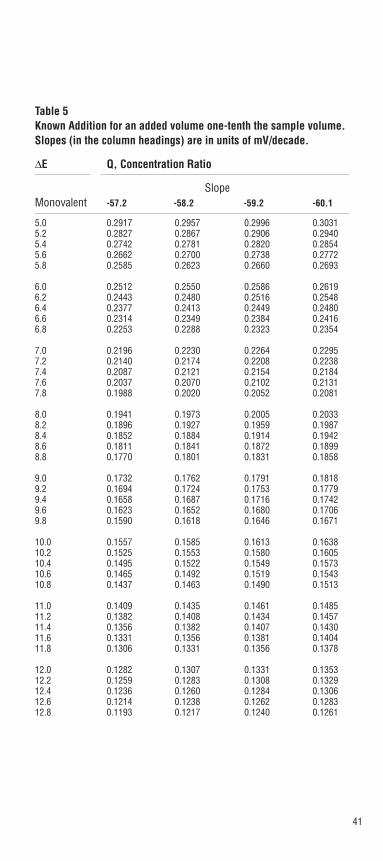
Table 5Known Addition for an added volume one-tenth the sample volume.Slopes (in the column headings) are in units of mV/decade.
∆E Q, Concentration Ratio
SlopeMonovalent -57.2 -58.2 -59.2 -60.1
5.0 0.2917 0.2957 0.2996 0.30315.2 0.2827 0.2867 0.2906 0.29405.4 0.2742 0.2781 0.2820 0.28545.6 0.2662 0.2700 0.2738 0.27725.8 0.2585 0.2623 0.2660 0.2693
6.0 0.2512 0.2550 0.2586 0.26196.2 0.2443 0.2480 0.2516 0.25486.4 0.2377 0.2413 0.2449 0.24806.6 0.2314 0.2349 0.2384 0.24166.8 0.2253 0.2288 0.2323 0.2354
7.0 0.2196 0.2230 0.2264 0.22957.2 0.2140 0.2174 0.2208 0.22387.4 0.2087 0.2121 0.2154 0.21847.6 0.2037 0.2070 0.2102 0.21317.8 0.1988 0.2020 0.2052 0.2081
8.0 0.1941 0.1973 0.2005 0.20338.2 0.1896 0.1927 0.1959 0.19878.4 0.1852 0.1884 0.1914 0.19428.6 0.1811 0.1841 0.1872 0.18998.8 0.1770 0.1801 0.1831 0.1858
9.0 0.1732 0.1762 0.1791 0.18189.2 0.1694 0.1724 0.1753 0.17799.4 0.1658 0.1687 0.1716 0.17429.6 0.1623 0.1652 0.1680 0.17069.8 0.1590 0.1618 0.1646 0.1671
10.0 0.1557 0.1585 0.1613 0.163810.2 0.1525 0.1553 0.1580 0.160510.4 0.1495 0.1522 0.1549 0.157310.6 0.1465 0.1492 0.1519 0.154310.8 0.1437 0.1463 0.1490 0.1513
11.0 0.1409 0.1435 0.1461 0.148511.2 0.1382 0.1408 0.1434 0.145711.4 0.1356 0.1382 0.1407 0.143011.6 0.1331 0.1356 0.1381 0.140411.8 0.1306 0.1331 0.1356 0.1378
12.0 0.1282 0.1307 0.1331 0.135312.2 0.1259 0.1283 0.1308 0.132912.4 0.1236 0.1260 0.1284 0.130612.6 0.1214 0.1238 0.1262 0.128312.8 0.1193 0.1217 0.1240 0.1261
42
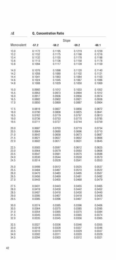
∆E Q, Concentration Ratio
SlopeMonovalent -57.2 -58.2 -59.2 -60.1
13.0 0.1172 0.1195 0.1219 0.123913.2 0.1152 0.1175 0.1198 0.121813.4 0.1132 0.1155 0.1178 0.119813.6 0.1113 0.1136 0.1158 0.117813.8 0.1094 0.1117 0.1139 0.1159
14.0 0.1076 0.1098 0.1120 0.114014.2 0.1058 0.1080 0.1102 0.112114.4 0.1041 0.1063 0.1084 0.110314.6 0.1024 0.1045 0.1067 0.108614.8 0.1008 0.1029 0.1050 0.1069
15.0 0.0992 0.1012 0.1033 0.105215.5 0.0953 0.0973 0.0994 0.101216.0 0.0917 0.0936 0.0956 0.097416.5 0.0882 0.0902 0.0921 0.093817.0 0.0850 0.0869 0.0887 0.0904
17.5 0.0819 0.0837 0.0856 0.087218.0 0.0790 0.0808 0.0825 0.084118.5 0.0762 0.0779 0.0797 0.081319.0 0.0736 0.0753 0.0770 0.078519.5 0.0711 0.0727 0.0744 0.0759
20.0 0.0687 0.0703 0.0719 0.073420.5 0.0664 0.0680 0.0696 0.071021.0 0.0642 0.0658 0.0673 0.068721.5 0.0621 0.0637 0.0652 0.066622.0 0.0602 0.0617 0.0631 0.0645
22.5 0.0583 0.0597 0.0612 0.062523.0 0.0564 0.0579 0.0593 0.060623.5 0.0547 0.0561 0.0575 0.058824.0 0.0530 0.0544 0.0558 0.057024.5 0.0514 0.0528 0.0541 0.0553
25.0 0.0499 0.0512 0.0525 0.053725.5 0.0484 0.0497 0.0510 0.052226.0 0.0470 0.0483 0.0495 0.050726.5 0.0456 0.0469 0.0481 0.049227.0 0.0443 0.0455 0.0468 0.0479
27.5 0.0431 0.0443 0.0455 0.046528.0 0.0419 0.0430 0.0442 0.045228.5 0.0407 0.0418 0.0430 0.044029.0 0.0395 0.0407 0.0418 0.042829.5 0.0385 0.0396 0.0407 0.0417
30.0 0.0374 0.0385 0.0396 0.040630.5 0.0364 0.0375 0.0385 0.039531.0 0.0354 0.0365 0.0375 0.038431.5 0.0345 0.0355 0.0365 0.037432.0 0.0335 0.0345 0.0356 0.0365
32.5 0.0327 0.0336 0.0346 0.035533.0 0.0318 0.0328 0.0337 0.034633.5 0.0310 0.0319 0.0329 0.033734.0 0.0302 0.0311 0.0320 0.032934.5 0.0294 0.0303 0.0312 0.0321

43
∆E Q, Concentration Ratio
SlopeMonovalent -57.2 -58.2 -59.2 -60.1
35.0 0.0286 0.0295 0.0305 0.031335.5 0.0279 0.0288 0.0297 0.030536.0 0.0272 0.0281 0.0290 0.029836.5 0.0265 0.0274 0.0282 0.029037.0 0.0258 0.0267 0.0275 0.0283
37.5 0.0252 0.0260 0.0269 0.027638.0 0.0246 0.0254 0.0262 0.027038.5 0.0240 0.0248 0.0256 0.026339.0 0.0234 0.0242 0.0250 0.025739.5 0.0228 0.0236 0.0244 0.0251
40.0 0.0223 0.0230 0.0238 0.024540.5 0.0217 0.0225 0.0232 0.023941.0 0.0212 0.0219 0.0227 0.023441.5 0.0207 0.0214 0.0221 0.022842.0 0.0202 0.0209 0.0216 0.0223
42.5 0.0197 0.0204 0.0211 0.021843.0 0.0192 0.0199 0.0206 0.021343.5 0.0188 0.0195 0.0202 0.020844.0 0.0183 0.0190 0.0197 0.020344.5 0.0179 0.0186 0.0192 0.0198
45.0 0.0175 0.0181 0.0188 0.019445.5 0.0171 0.0177 0.0184 0.019046.0 0.0167 0.0173 0.0179 0.018546.5 0.0163 0.0169 0.0175 0.018147.0 0.0159 0.0165 0.0171 0.0177
47.5 0.0156 0.0162 0.0168 0.017348.0 0.0152 0.0158 0.0164 0.016948.5 0.0148 0.0154 0.0160 0.016649.0 0.0145 0.0151 0.0157 0.016249.5 0.0142 0.0147 0.0153 0.0158
50.0 0.0139 0.0144 0.0150 0.015550.5 0.0135 0.0141 0.0146 0.015151.0 0.0132 0.0138 0.0143 0.014851.5 0.0129 0.0135 0.0140 0.014552.0 0.0126 0.0132 0.0137 0.0142
52.5 0.0124 0.0129 0.0134 0.013953.0 0.0121 0.0126 0.0131 0.013653.5 0.0118 0.0123 0.0128 0.013354.0 0.0116 0.0120 0.0125 0.013054.5 0.0113 0.0118 0.0123 0.0127
55.0 0.0110 0.0115 0.0120 0.012555.5 0.0108 0.0113 0.0118 0.012256.0 0.0106 0.0110 0.0115 0.011956.5 0.0103 0.0108 0.0113 0.011757.0 0.0101 0.0106 0.0110 0.0114
57.5 0.0099 0.0103 0.0108 0.011258.0 0.0097 0.0101 0.0105 0.011058.5 0.0095 0.0099 0.0103 0.010759.0 0.0093 0.0097 0.0101 0.010559.5 0.0091 0.0095 0.0099 0.010360.0 0.0089 0.0093 0.0097 0.0101

44
ELECTRODE STORAGE
Orion 9307 Nitrate Half-Cell Electrode
The nitrate sensing module should be kept in the glass vial until used.The assembled electrode can be stored in nitrate standard. For longperiods of time (over 2-3 days), disassemble the nitrate electrode, rinsethoroughly with distilled water, blot dry, and store the module in its vial.
Orion 9707 ionplus® Nitrate Electrode
The solution in the Orion 9707 ionplus® Combination Nitrate Electrodeshould not be allowed to evaporate and crystallize around the junction.
For short periods of time (2-3 days):
Store the assembled electrode in nitrate standard, such as 100 ppm as N.
For storage longer than 2-3 days:
Drain the reference compartment of the electrode and flush it with distilled water. Disassemble the electrode, see Figure 2, as follows toremove the nitrate sensing module:
1. Grasp the outer body sleeve. With your other hand, unscrew theelectrode cap. Allow cap and spring assembly to slide down theelectrode cable.
2. Push the inner stem of the electrode handle out through the outerelectrode sleeve, exposing the sensing module.
3. Rinse the inner stem and module well with distilled water. Blot drygently in order not to damage the sensing membrane.
4. Carefully unscrew the sensing module from the inner stem, taking care not to touch the sensing membrane.
5. Place the nitrate sensing module into the glass vial until it is to beused again.
6. Gently dry the inside of the inner stem and o-ring area with a lint-free tissue and reassemble the electrode handle. Store dry.
Orion 90-02 Double Junction Reference Electrode

45
The Orion 90-02 Reference Electrode may be stored in air betweensample measurements (up to 1 hour).
For short periods of time (up to one week):
The Orion 90-02 may be stored in its filling solution or distilled water. Do not allow the solution inside the electrode to evaporate and crystallize.
For long periods of time (over one week):
Drain the reference electrode completely, rinse with distilled water, and store dry.
46
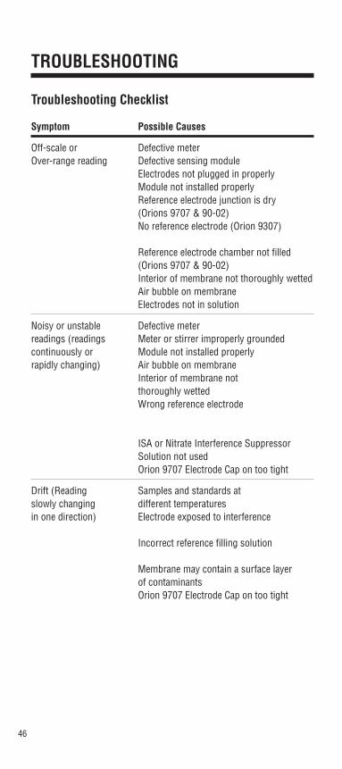
TROUBLESHOOTING
Troubleshooting Checklist
Symptom Possible Causes
Off-scale or Defective meterOver-range reading Defective sensing module
Electrodes not plugged in properly Module not installed properly Reference electrode junction is dry (Orions 9707 & 90-02)No reference electrode (Orion 9307)
Reference electrode chamber not filled (Orions 9707 & 90-02)Interior of membrane not thoroughly wettedAir bubble on membrane Electrodes not in solution
Noisy or unstable Defective meterreadings (readings Meter or stirrer improperly groundedcontinuously or Module not installed properlyrapidly changing) Air bubble on membrane
Interior of membrane not thoroughly wettedWrong reference electrode
ISA or Nitrate Interference Suppressor Solution not usedOrion 9707 Electrode Cap on too tight
Drift (Reading Samples and standards at slowly changing different temperaturesin one direction) Electrode exposed to interference
Incorrect reference filling solution
Membrane may contain a surface layer of contaminantsOrion 9707 Electrode Cap on too tight

47
Solution
Check meter with shorting strap (See meter instruction manual)Refer to Troubleshooting GuideUnplug electrodes and reseat Check electrode assembly Through the reference junction, expel a few drops of filling solution
Use Orion 90-02 Reference Electrode (with Orion 9307 Nitrate Electrode)Be sure reference electrode is filled with correct solution See Electrode Assembly and PreparationTap module gently or shake down like a clinical thermometerRemove air bubble on electrode by gently tapping itPut electrodes in solution
Check meter with shorting strap (See meter instruction manual)Check meter and stirrer for grounding Check Before Using the Electrode Remove air bubble by gently tapping electrodeTap module gently or shake down like a clinical thermometer
Use Orion 90-02 Double Junction Reference Electrode (with Orion 9307 Nitrate Electrode) Do not use calomel or Ag/AgCl (frit- or fiber-type) reference electrode Use recommended ISA, Orion 930711 or Nitrate InterferenceSuppressor Solution, Orion 930710Reassemble electrode. See Electrode Assembly and Preparation
Allow solutions to come to room temperature before measurementSee Electrode Assembly and PreparationUse nitrate interference suppressor solution, 930710. See InterferencesUse recommended filling solution. See Electrode Assembly and PreparationRinse electrode with distilled water and soak in nitrate standard (10 -2 M) for 1 hourReassemble electrode. See Electrode Assembly and Preparation

48
Troubleshooting Checklist (cont.)
Symptom Possible Causes
Low slope or Electrodes not properly conditionedNo slope Standards contaminated or
incorrectly madeISA or Nitrate Interference Suppressor Solution not usedStandard used as ISA or Nitrate Interference Suppressor SolutionOrion 9707 Electrode Cap on too tightDefective sensing moduleElectrode exposed to interferences
“Wrong Answer” Incorrect scaling of semilog paper (But calibrationcurve is OK)
Incorrect standardsIncorrect signWrong units used

49
Solution
See Electrode Assembly and PreparationPrepare fresh standards
Use recommended ISA, Orion 930711 or Nitrate InterferenceSuppressor Solution, Orion 930710Use ISA or Nitrate Interference Suppressor Solution!
Reassemble electrode. See Electrode Assembly and PreparationRefer to Troubleshooting GuideSee Interferences. Use Nitrate Interference Suppressor Solution,Orion 930710
Plot millivolts on the linear axis. On the log axis, be sure concentration numbers within each decade are increasing withincreasing concentrationPrepare fresh standardsBe sure to note sign of millivolt value correctlyApply correct conversion factor: 10 -3 M = 62 ppm as NO3
- = 14 ppm as N
For additional information on blank correction with your meter, see meter instruction manual
50
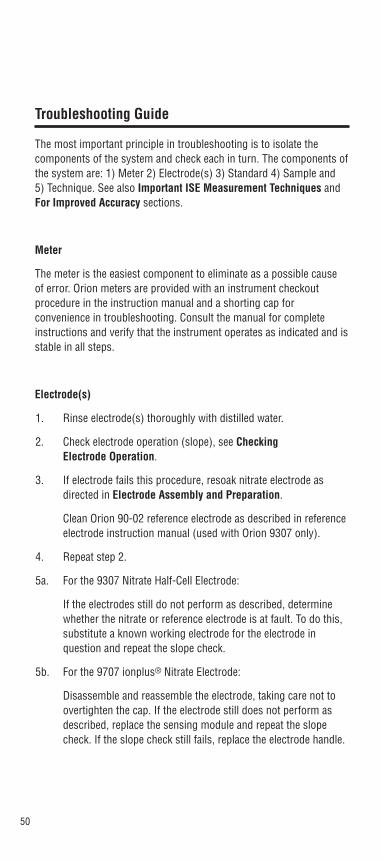
Troubleshooting Guide
The most important principle in troubleshooting is to isolate the components of the system and check each in turn. The components ofthe system are: 1) Meter 2) Electrode(s) 3) Standard 4) Sample and 5) Technique. See also Important ISE Measurement Techniques and For Improved Accuracy sections.
Meter
The meter is the easiest component to eliminate as a possible cause of error. Orion meters are provided with an instrument checkoutprocedure in the instruction manual and a shorting cap forconvenience in troubleshooting. Consult the manual for completeinstructions and verify that the instrument operates as indicated and isstable in all steps.
Electrode(s)
1. Rinse electrode(s) thoroughly with distilled water.
2. Check electrode operation (slope), see Checking Electrode Operation.
3. If electrode fails this procedure, resoak nitrate electrode asdirected in Electrode Assembly and Preparation.
Clean Orion 90-02 reference electrode as described in referenceelectrode instruction manual (used with Orion 9307 only).
4. Repeat step 2.
5a. For the 9307 Nitrate Half-Cell Electrode:
If the electrodes still do not perform as described, determinewhether the nitrate or reference electrode is at fault. To do this,substitute a known working electrode for the electrode inquestion and repeat the slope check.
5b. For the 9707 ionplus® Nitrate Electrode:
Disassemble and reassemble the electrode, taking care not toovertighten the cap. If the electrode still does not perform asdescribed, replace the sensing module and repeat the slopecheck. If the slope check still fails, replace the electrode handle.

51
6. If the stability and slope check out properly, but measurementproblems persist, the sample may contain interferences orcomplexing agents, or the technique may be in error. SeeStandard, Sample, and Technique sections below.
7. Before replacing a “faulty” electrode, or if another electrode isnot available for test purposes, review the instruction manualand be sure to:
• Clean the electrode thoroughly
• Prepare the electrode properly
• Check that the Orion 9707 Electrode cap is not too tight
• Use proper filling solution, ISA, and standards
• Measure correctly
• Review Troubleshooting Checklist
Standard
The quality of results depends greatly upon the quality of thestandards. ALWAYS prepare fresh standards when problems arise – itcould save hours of frustrating troubleshooting! Error may result fromcontamination of prepared standards, quality of dilution, distilledwater, or a numerical error in calculating the concentrations.
The best method for preparation of standards is serial dilution. Thisprocedure involves preparing an initial standard that is diluted toprepare a second standard solution using volumetric glassware. Thesecond is similarly diluted to prepare a third standard, and so on, untilthe desired range of standards has been prepared.
Sample
If the electrodes work properly in standards but not in the sample,look for possible interferences, complexing agents, or substances thatcould affect response or physically damage the sensing electrode orthe reference electrode. If possible, determine the composition of thesamples and check for problems. See Sample Requirements,Interferences, and Specifications.
52
Technique
Check the method of analysis for compatibility with your sample.Direct measurement may not always be the method of choice. If theionic strength varies markedly from sample to sample, known addition may be best. If working at low levels, be sure to follow thelow-level measurement technique. Also, be sure that the expected concentration of the ion of interest is within the electrode’s limits ofdetection. If problems persist, review operational procedures andinstruction manuals to be sure that proper technique has beenfollowed. Read Important ISE Measurement Techniques and Measurement Procedures.

53
Assistance
After troubleshooting all components of your measurement system,contact The Technical EdgeSM for Orion products. Within the UnitedStates call 1.800.225.1480, outside the United States call978.232.6000 or fax 978.232.6031. In Europe, the Middle East andAfrica, contact your local authorized dealer. For the most currentcontact information, visit www.thermo.com.

54
ELECTRODE CHARACTERISTICS
Electrode Response
The electrode potential plotted against concentration on semi-logarithmic paper results in a straight line with a slope of about -54 to -60 mV per decade until concentration reaches 10-4 M NO3
-. See Figure 4.
The electrode exhibits good time response (98% in one minute or less) for nitrate concentrations above 10-3 M NO3
-. Below this valueresponse times vary from 2 to 5 minutes. See Figure 5.
Limits of Detection
In pure sodium nitrate solutions, the upper limit of detection is 1 M.When possible, dilute the sample to the linear working range of theelectrode. If this is not possible, the possibility of a liquid junctionpotential developing at the reference electrode and the “salt extractioneffect” need to be considered. At high salt concentrations, some saltsmay be extracted into the electrode membrane, causing deviation from theoretical response. To measure samples between 10-1 and 1 M, calibrate the electrode at 4 or 5 intermediate points, or dilute the sample.
The lower limit of detection is determined by the slight water solubilityof the ion exchanger, which causes deviation from theoreticalresponse. Figure 4 shows the theoretical response at low levels ofnitrate compared to the actual response. If nitrate measurements aremade below 10-4 M (1.4 ppm as N), a low-level measurementprocedure is recommended.
Reproducibility
Reproducibility is limited by factors such as temperature fluctuations,drift, and noise. Within the electrode operating range, reproducibility is independent of concentration. With calibration every hour, direct electrode measurements reproducible to ± 2% can be obtained.
Temperature Effects
Since electrode potentials are affected by changes in temperature,samples and standard solutions should be within ± 1°C (± 2°F) of eachother. At the 10-3 M level, a 1°C difference in temperature results in a1.5% error. The absolute potential of the reference electrode changes

55
slowly with temperature because of the solubility equilibria on whichthe electrode depends. The slope of the nitrate electrode also varieswith temperature, as indicated by the factor “S” in the Nernst equation.Values for the change in slope for nitrate ion are given in Table 6. If temperature changes occur, meter and electrodes should be recalibrated.
The electrode can be used at temperatures from 0 to 40°C, providedthat temperature equilibrium has occurred. For use at temperaturessubstantially different from room temperature, equilibrium times of upto one hour are recommended.
The isopotential concentration, Ciso, for Orion 9707 ionplus® electrodeis approximately 3.2 x 10⁻³ M.
Table 6Values of Electrode Slope vs. Temperature
T °C S T °C S
0 -54.20 30 -60.15
10 -56.18 40 -62.13
20 -58.16 50 -64.11
25 -59.16
Figure 5Typical Electrode Response to NaNO3
- 35
+ 15
+ 40
+ 65
+ 90
+ 115
- 10
1 2 3 4 5 6 7time (minutes)
10-3 M to 10-5 M NaNO3
10-3 M to 10-4 M NaNO3
10-3 M to 10-2 M NaNO3
electrodepotential(mV)
10-3 M to 10-6 M NaNO3

56
Interferences
Some anions, if present at high enough levels, are electrodeinterferences and will cause measurement errors. Table 7 indicateslevels of common anions that will cause 10% error at variousconcentrations of nitrate.
In many samples anions listed in Table 7 are absent or insignificantlylow. Many of the interferences can be removed or minimized by the following procedures (letters refer to letters in Table 7):
a. Carbonate and bicarbonate can be removed by acidifying the sample to pH 4.5 with sulfuric acid, converting the ions to carbon dioxide.
b. These interferences can be minimized by precipitation with silver. Dissolve solid silver sulfate in samples to effect removal.
c. Nitrite can be removed by adding sufficient sulfamic acid to samples.
d. These interferences cannot be removed. Use Orion Nitrate Test Kit, Orion 700005, to convert nitrate to ammonia. Measure using ammonia electrode, Orion 9512. As an alternate method, convert nitrate to nitrite with a reduction column and measure nitrite levels with a nitrite electrode (Orion 9746 or 9346). For more information contact Orion Technical Service.
e. Many organic (carboxylic) anions also interfere with the nitrate electrode. These anions can be removed by using a 1 M ISA solution.
NOTE: Use of any of the above procedures require similar treatment of standards as well as samples.
Thermo offers a Nitrate Interference Suppressor Solution ( Orion930710), recommended for the removal of a variety of interferinganions present in samples such as soils or plant tissues.
The Nitrate Interference Suppressor Solution is mixed in an equal volume with samples and also with standards. For example, 25 mL of sample would be mixed with 25 mL of the Nitrate InterferenceSuppressor Solution. This procedure ensures that samples and standards have a similar background, and that no correction factor isneeded for the dilution.

57
If the electrode is exposed to high levels of interfering ions, it maybecome drifty and sluggish in response. When this happens, restorenormal performance as outlined in Troubleshooting.
When the level of interferences in samples is constant, it is sometimespossible to measure nitrate accurately when interference levels arehigher than those in Table 7. Call or write Thermo Electron’s TechnicalService Chemists for more information. See Assistance.
Electrode Life
Each sensing module should last at least three months in normal laboratory use. In time, electrode slope will decrease and readings willstart to drift, indicating that the module should be changed. Beforereplacement, refer to Troubleshooting Checklist, to make sure that thedifficulties are caused by the sensing module.
Table 7Levels of Possible Interferences Causing a 10% Error
InterferencesMoles/Liter 10-4 M 10-3 M 10-2 M
(d) ClO4- 1 x 10⁻⁸ 1 x 10⁻⁷ 1 x 10⁻⁶
(b) I- 5 x 10⁻⁷ 5 x 10⁻⁶ 5 x 10⁻⁵
(d) ClO3- 5 x 10⁻⁶ 5 x 10⁻⁵ 5 x 10⁻⁴
(b) CN- 1 x 10⁻⁵ 1 x 10⁻⁴ 1 x 10⁻³
(b) Br- 7 x 10⁻⁵ 7 x 10⁻⁴ 7 x 10⁻³
(c) NO2- 7 x 10⁻⁵ 7 x 10⁻⁴ 7 x 10⁻³
(b) HS- 1 x 10⁻⁴ 1 x 10⁻³ 1 x 10⁻²
(a) HCO3- 1 x 10⁻³ 1 x 10⁻² 0.1
(a) CO32- 2 x 10⁻³ 2 x 10⁻² 0.2
(b) Cl- 3 x 10⁻³ 3 x 10⁻² 0.3
(b) H2PO4- 5 x 10⁻³ 5 x 10⁻² 0.5
(b) HPO42- 5 x 10⁻³ 5 x 10⁻² 0.5
(b) PO43- 5 x 10⁻³ 5 x 10⁻² 0.5
(e) OAc- 2 x 10⁻² 0.2 2
F- 6 x 10⁻² 0.6 6
SO42- 0.1 1.0 10
Letters in parentheses refer to comments in the Interferences section.

58
Interferences to NO3- as N
ppm 1 ppm 10 ppm 100 ppm
(d) ClO4- 7 x 10⁻⁴ 7 x 10⁻³ 7 x 10⁻²
(b) I- 4 x 10⁻² 0.4 4
(d) ClO3- 0.3 3 30
(b) CN- 0.2 2 20
(b) Br- 4 40 400
(c) NO2- 2 23 230
(b) HS- 2 23 230
(a) HCO3- 44 440 4400
(a) CO32- 86 860 8600
(b) Cl- 76 760 7600
(b) H2PO4- 346 3464 34640
(b) HPO42- 343 3430 34300
(b) PO43- 339 3390 33900
(e) OAc- 1042 10420 104200
F- 814 8140 81400
SO42- 6857 68570 685700
Letters in parentheses refer to comments in the Interferences section.

59
Theory of Operation
The nitrate electrode consists of an electrode body and a replaceablepretested sensing module. The sensing module contains a liquid internal filling solution in contact with a gelled organophilic membranecontaining a nitrate selective ion exchanger. See Figure 6.
Figure 6Example of Ion Sensing Module
modulehousing
electricalcontact
internalreferenceelement(Ag/AgCI)
porousplasticorganphilicmembrane
ionsensitivearea
internalaqueousreferencesolution
When the membrane is in contact with a nitrate solution, an electrodepotential develops across the membrane. This potential, whichdepends on the level of free nitrate ion in solution, is measured againsta constant reference potential with a pH/mV meter or specific ionmeter. The measured potential corresponding to the level of nitrate ionin solution is described by the Nernst equation:
E = Eo + S log (A)
where:
E = measured electrode potential
Eo = reference potential (a constant)
A = nitrate ion level in solution
S = electrode slope (about -56 mV per decade)

60
The level of nitrate ion, A, is the activity or “effective concentration” of free nitrate ion in solution. The total nitrate concentration, Ct,includes some bound or complexed ions as well as free ions, whoseconcentration is:
Ct = Cf + Cb
where:
Cb = concentration of nitrate ions in all bound or complexed forms
Cf = concentration of free nitrate ions
The nitrate ion activity is related to free nitrate ion concentration by theactivity coefficient:
A = γ Cf
Ionic activity coefficients are variable and largely depend on total ionicstrength. Ionic strength is defined as:
Ionic strength = 1 ⁄ 2∑(CiZi2)
Ci = concentration of ion i
Zi = charge of ion i
If the background ionic strength is high and constant relative to thesensed ion concentration, the activity coefficient is constant and activity is directly proportional to concentration.
Ionic strength adjustor (ISA) is added to nitrate standards andsamples so that the background ionic strength is high and constantrelative to variable concentrations of nitrate ion. For the nitrateelectrode, (NH4)2SO4 is the recommended ISA. Nitrate InterferenceSuppression Solution, a specific solution for removal of nitrate-interfering ions, is recommended for samples with competing ions.Other solutions can be used as long as they do not contain ions thatwould interfere with the electrode’s response to nitrate ion.

61
Reference electrode conditions must also be considered. Liquid junction potentials arise any time two solutions of differentcomposition are brought into contact. The potential results from theinterdiffusion of ions in the two solutions. Since ions diffuse atdifferent rates, the electrode charge will be carried unequally acrossthe solution boundary resulting in a potential difference between thetwo solutions. In making electrode measurements, it is important thatthis potential be the same when the reference is in the standardizingsolution as well as in the sample solution; otherwise, the change inliquid junction potential will appear as an error in the measuredspecific ion electrode potential.
The most important variable which analysts have under their control is the composition of the liquid junction filling solution. The fillingsolution should be equitransferent. That is, the speed with which thepositive and negative ions in the filling solution diffuse into the sampleshould be as nearly equal as possible. If the rate at which positive and negative charge is carried into the sample solution is equal, thenno junction potential can result. Using the Optimum Results F filling solution will minimize junction potential in most samples.

62

63
WARRANTY
For the most current warranty information, visit www.thermo.com.
The Thermo Electron Corporation, Orion products warranty coversfailures due to manufacturer’s workmanship or material defects fromthe date of purchase by the user. User should return the warranty cardand retain proof of purchase. Warranty is void if product has beenabused, misused, or repairs attempted by unauthorized persons.
Warranties herein are for product sold/installed by Thermo or itsauthorized dealers.
Any product sold by a U.S. or Canadian distributor must be returned toThermo for any warranty work. Please contact our Technical Servicedepartment for further information. A Return Authorization Numbermust be obtained from The Technical EDGESM For Orion Productsbefore returning any product for in-warranty repair or replacement.
In the event of failure within the warranty period, Thermo will at thecompany’s option, repair or replace product not conforming to thiswarranty. There may be additional charges, including freight, forwarranty service performed in some countries. For service, callThermo or its authorized dealer outside the United States and Canada.Thermo reserves the right to ask for proof of purchase, such as theoriginal invoice or packing slip.
Field Service is available on Orion BOD AutoEZ™, EZ Flash® GCAccessory and TEA Analyzer®. Contact our Field Service departmentfor details on quotations, service, other field service-related activities.
The following products are warranted to be free from defects inmaterial and workmanship in the period listed below from the date ofpurchase from the user or from the date of shipment from Thermo,whichever is earlier, provided use is in accordance with the operatinglimitations and maintenance procedures in the instruction manual andwhen not having been subjected to accident, alteration, misuse, abuseor breakage of electrodes:
Thirty-six months from date of purchase by the user (or forty-twomonths from date of shipment from Thermo)
• Waterproof Meters (Orion 630, 635, 830A, 835A, 260A, 261S,265A, 266S, 130A, 131S, 135A, 136S, 1230, 142 and 842),Conductivity Meters (Orion 105Aplus™, 115Aplus™, 125Aplus™,145Aplus™, 150Aplus™ and 162A), PerpHect® pH/ISE Meters(Orion 310, 320, 330, 350, 370) pH/ISE Meters (Orion 210Aplus™,230Aplus™, 250Aplus™, 290Aplus™, 410Aplus™, 420Aplus™,520Aplus™, 525Aplus™, 710Aplus™, 720Aplus™ and 920Aplus™),pHuture MMS™ Meters (Orion 535A and 555A), pH/ConductivityMeter (Orion 550A), Dissolved Oxygen Meters (Orion 805Aplus™,810Aplus™, 850Aplus™ and 862A).
64
Twenty-four months from date of purchase by the user (or thirty-sixmonths from date of shipment from Thermo)
• Orion ROSS Ultra® Electrodes, AQUAfast® IV Colorimeters,AQUAfast® IV Turbidimeter, Orion 925 Flash Titrator™, Series 100DuraProbe™ Conductivity Cells and Series 800 Dissolved OxygenProbes.
Twelve months from date of purchase by the user (or eighteenmonths from date of shipment from Thermo)
• Laboratory pH Meters, (Orion 301, 611 and 940), SensorLink®,pHuture™ pH Meters (Orion 610 and 620), Smart Chek™ meters,Sage® Pumps, Cahn® Balances, 930 Ionalyzer®, 950 ROSS™ FASTQC™ Titrator, 960 Titrator PLUS®, Karl Fischer Titrators,Autosamplers, Liquid Handling Devices, Liquid HandlingAutomation Workstations (Orion AS2000, AS2500 and AS4000),Pumps (Orion SP201, SP201-HR, SP201-S, Peristaltic and Rinse),pHuture® Conversion Box, Wine Master®, 607 Switchbox, rf link™,AQUAfast® II Colorimeters, Vacuum Degasser and Flowmeter.
• Orion EZ Flash® GC Accessory, Orion TEA Analyzer® 610 and 510excluding consumable items carry twelve months warranty only.
• Orion Ion Selective Electrodes, ionplus® Electrodes, ROSS™
Electrodes, Sure-Flow® Electrodes, PerpHecT® Electrodes,AquaPro Professional Electrodes, No Cal™ pH electrodes, StandardLine pH Electrodes, Tris pH Electrodes, KNIpHE® electrode, ORPTriode™ (Orion 9180BN), pHuture™ pH Probes (Orion 616500) andpHuture MMS™ Quatrode™ and Triode™ (Orion 616600 and617900), Orion 97-08 DO Probe, Series 100 ConventionalConductivity Cells, temperature probes and compensators (exceptthose products noted).
• Orion 93 and 97 ionplus Series sensing modules are warranted togive six months of operation if placed in service before the dateindicated on the package, except 93-07 and 97-07 Nitrate modulesare warranted to give ninety days of operation if placed in servicebefore the date indicated on the package.
Six months from date of purchase by the user (or twelve monthsfrom date of shipment from Thermo)
• Orion Flash Titration™ Probe (Orion 092518), pHuture™ Electrode

65
(Orion 615700), pHuture MMS™ Pentrode™ (Orion 617500),Quatrode™ (Orion 617800) and Triode™ (Orion 615800), LowMaintenance Triode™ (Orion 9107BN), ORP Low MaintenanceTriode™ (Orion 9179BN), and PerpHecT® Low Maintenance Triode™
(Orion 9207BN), Waterproof Triode™ (Orion 9107WP, 9107WL,9109WL and 9109WP), QuiKcheK® Meters and Micro Electrodes.
Three months from date of purchase by the user (or six months fromdate of shipment from Thermo)
• Economy Line Electrodes, Orion 91-05, 91-06, 91-15, 91-16, 91-25, 91-26, 91-35, 91-36, 92-06. Warranty also includes failure forany reason (excluding breakage), except abuse, provided theelectrode is not used in solutions containing silver, sulfide,perchlorate, or hydrofluoric acid; or in solutions more than one (1)Molar in strong acid or base at temperatures above 50 °C.
“Out-of-Box” Warranty - Should any of the following products fail towork when first used, contact Thermo immediately for replacement.
• Orion Solutions, Standards, Reagents, Cables, Ferrules, Tubing,Line adapters, Printers, Software, Cases, Stands, ProbeMembranes, AQUAfast® Test Strips, EZ Flash® columns, LiquidHandling Probes, Adapter Plates and Racks and generalaccessories.
For products in the catalog not listed in this warranty statement, pleasevisit our website at: www.thermo.com
THE WARRANTIES DESCRIBED ABOVE ARE EXCLUSIVE AND IN LIEUOF ALL OTHER WARRANTIES WHETHER STATUTORY, EXPRESS ORIMPLIED INCLUDING, BUT NOT LIMITED TO, ANY IMPLIEDWARRANTY OF MERCHANTABILITY OR FITNESS FOR A PARTICULARPURPOSE AND ALL WARRANTIES ARISING FROM THE COURSE OFDEALING OR USAGE OF TRADE. THE BUYER’S SOLE AND EXCLUSIVEREMEDY IS FOR REPAIR OR REPLACEMENT OF THE NON-CONFORMING PRODUCT OR PART THEREOF, OR REFUND OF THEPURCHASE PRICE, BUT IN NO EVENT SHALL THERMO (ITSCONTRACTORS AND SUPPLIERS OF ANY TIER) BE LIABLE TO THEBUYER OR ANY PERSON FOR ANY SPECIAL, INDIRECT, INCIDENTAL,OR CONSEQUENTIAL DAMAGES WHETHER THE CLAIMS ARE BASEDIN CONTRACT, IN TORT (INCLUDING NEGLIGENCE), OR OTHERWISEWITH RESPECT TO OR ARISING OUT OF THE PRODUCT FURNISHEDHEREUNDER.

66
REPRESENTATION AND WARRANTIES MADE BY ANY PERSON,INCLUDING ITS AUTHORIZED DEALERS, REPRESENTATIVES ANDEMPLOYEES OF THERMO WHICH ALTER OR ARE IN ADDITION TOTHE TERMS OF THIS WARRANTY SHALL NOT BE BINDING UPONTHERMO UNLESS IN WRITING AND SIGNED BY ONE OF ITSOFFICERS.

67
ORDERING INFORMATION
Orion No. Description
9307BN Orion 9307 Nitrate Plastic Membrane Half-cell Electrode, BNC connector
930700 Orion 9307 Nitrate Plastic Membrane Half-cell Electrode, U.S. Standard connector
9707BN Orion 9707 ionplus® Nitrate Combination Plastic Membrane Electrode, BNC connector
090032 BNC Electrode to U.S. Standard Meter Adapter
900200 Orion 90-02 Double Junction Sure-Flow® Reference Electrode
900046 Optimum Results™ F Reference Filling Solution, 5 x 60 mL bottles
900002 Inner Chamber Filling Solution for Orion 90-02 Reference Electrode, 5 x 60 mL bottles
920706 Nitrate Standard Solution (0.1 M), 475 mL
920707 Nitrate Standard Solution (1000 ppm as N), 475 mL
930707 Nitrate Standard Solution (100 ppm as N), 475 mL
930711 Nitrate Ionic Strength Adjustor Solution, 475 mL
930710 Nitrate Interference Suppressor Solution, 475 mL
970701 Replacement Sensing Module for Orion 9707 ionplus® Nitrate electrode, each
930701 Replacement Electrode Module for Orion 9307 Nitrate electrode, package of 3
930702 Replacement Electrode module (one) for Orion 9307 Nitrate electrode.
9700BN Replacement ionplus® Electrode Handle, with BNC connector
9300BN Replacement Electrode Body, with BNC connector
930000 Replacement Electrode Body, with U.S. Standard connector
900060 ionplus® Stirring Accessory
68
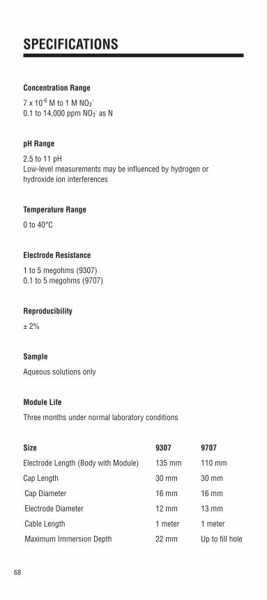
SPECIFICATIONS
Concentration Range
7 x 10⁻⁶ M to 1 M NO3-
0.1 to 14,000 ppm NO3- as N
pH Range
2.5 to 11 pHLow-level measurements may be influenced by hydrogen or hydroxide ion interferences
Temperature Range
0 to 40°C
Electrode Resistance
1 to 5 megohms (9307)0.1 to 5 megohms (9707)
Reproducibility
± 2%
Sample
Aqueous solutions only
Module Life
Three months under normal laboratory conditions
Size 9307 9707
Electrode Length (Body with Module) 135 mm 110 mm
Cap Length 30 mm 30 mm
Cap Diameter 16 mm 16 mm
Electrode Diameter 12 mm 13 mm
Cable Length 1 meter 1 meter
Maximum Immersion Depth 22 mm Up to fill hole

224995-001 Rev. D
Environmental InstrumentsWater Analysis
North America 166 Cummings CenterBeverly, MA 01915 USATel: 978-232-6000Dom. Fax: 978-232-6015Int’l. Fax: 978-232-6031
Europe12-16 Sedgeway Business ParkWitchford, CambridgeshireEngland, CB6 2HYTel: 44-1353-666111Fax: 44-1353-666001
Far EastRoom 904, Federal Building369 Lockhart RoadWanchai, Hong KongTel: 852-2836-0981Fax: 852-2834-5160
Customer Support Toll Free: 800-225-1480 www.thermo.com Dom. e-mail: [email protected]’l. e-mail: [email protected]
For updated contact information, visit www.thermo.com
Analyze • Detect • Measure • Control™