NIH Public Access Comput Methods Biomech Biomed Engin · Comput Methods Biomech Biomed Engin....
18
3D Finite Element Models of Shoulder Muscles for Computing Lines of Actions and Moment Arms Joshua D. Webb, PhD 1 , Silvia S. Blemker, PhD 2 , and Scott L. Delp, PhD 1 1 Departments of Bioengineering and Mechanical Engineering, Stanford University, Stanford, CA 94305 2 Departments of Mechanical and Aerospace Engineering, Biomedical Engineering, and Orthopaedic Surgery, University of Virginia, Charlottesville, VA 22904 Abstract Accurate representation of musculoskeletal geometry is needed to characterize the function of shoulder muscles. Previous models of shoulder muscles have represented muscle geometry as a collection of line segments, making it difficult to account the large attachment areas, muscle- muscle interactions, and complex muscle fiber trajectories typical of shoulder muscles. To better represent shoulder muscle geometry we developed three-dimensional finite element models of the deltoid and rotator cuff muscles and used the models to examine muscle function. Muscle fiber paths within the muscles were approximated, and moment arms were calculated for two motions: thoracohumeral abduction and internal/external rotation. We found that muscle fiber moment arms varied substantially across each muscle. For example, supraspinatus is considered a weak external rotator, but the three-dimensional model of supraspinatus showed that the anterior fibers provide substantial internal rotation while the posterior fibers act as external rotators. Including the effects of large attachment regions and three-dimensional mechanical interactions of muscle fibers constrains muscle motion, generates more realistic muscle paths, and allows deeper analysis of shoulder muscle function. Keywords Rotator Cuff; Deltoid; 3D Finite-Element Muscle Model; Musculoskeletal Model; Shoulder Biomechanics Introduction Musculoskeletal models of the shoulder typically represent muscle lines of action as a collection of line segments (Garner and Pandy 2001, Holzbaur et al. 2005, van der Helm 1994). These models have been useful for a wide variety of applications including simulating surgical procedures (Holzbaur, et al. 2005), investigating wheelchair mechanics (van der Helm and Veeger 1996, van der Woude et al. 2001), and controlling neuroprostheses (Blana et al. 2009, Hincapie et al. 2008). However, shoulder muscles have Corresponding Author: Scott L. Delp, Stanford University, Clark Center Room S321; 318 Campus Drive; Stanford, CA 94305-5444, Telephone: (650) 723-1230; Fax: (650) 723-8544; [email protected]. NIH Public Access Author Manuscript Comput Methods Biomech Biomed Engin. Author manuscript; available in PMC 2015 January 21. Published in final edited form as: Comput Methods Biomech Biomed Engin. 2014 ; 17(8): 829–837. doi:10.1080/10255842.2012.719605. NIH-PA Author Manuscript NIH-PA Author Manuscript NIH-PA Author Manuscript
Transcript of NIH Public Access Comput Methods Biomech Biomed Engin · Comput Methods Biomech Biomed Engin....

3D Finite Element Models of Shoulder Muscles for Computing Lines of Actions and Moment Arms
Joshua D. Webb, PhD1, Silvia S. Blemker, PhD2, and Scott L. Delp, PhD1
1Departments of Bioengineering and Mechanical Engineering, Stanford University, Stanford, CA 94305
2Departments of Mechanical and Aerospace Engineering, Biomedical Engineering, and Orthopaedic Surgery, University of Virginia, Charlottesville, VA 22904
Abstract
Accurate representation of musculoskeletal geometry is needed to characterize the function of
shoulder muscles. Previous models of shoulder muscles have represented muscle geometry as a
collection of line segments, making it difficult to account the large attachment areas, muscle-
muscle interactions, and complex muscle fiber trajectories typical of shoulder muscles. To better
represent shoulder muscle geometry we developed three-dimensional finite element models of the
deltoid and rotator cuff muscles and used the models to examine muscle function. Muscle fiber
paths within the muscles were approximated, and moment arms were calculated for two motions:
thoracohumeral abduction and internal/external rotation. We found that muscle fiber moment arms
varied substantially across each muscle. For example, supraspinatus is considered a weak external
rotator, but the three-dimensional model of supraspinatus showed that the anterior fibers provide
substantial internal rotation while the posterior fibers act as external rotators. Including the effects
of large attachment regions and three-dimensional mechanical interactions of muscle fibers
constrains muscle motion, generates more realistic muscle paths, and allows deeper analysis of
shoulder muscle function.
Keywords
Rotator Cuff; Deltoid; 3D Finite-Element Muscle Model; Musculoskeletal Model; Shoulder Biomechanics
Introduction
Musculoskeletal models of the shoulder typically represent muscle lines of action as a
collection of line segments (Garner and Pandy 2001, Holzbaur et al. 2005, van der Helm
1994). These models have been useful for a wide variety of applications including
simulating surgical procedures (Holzbaur, et al. 2005), investigating wheelchair mechanics
(van der Helm and Veeger 1996, van der Woude et al. 2001), and controlling
neuroprostheses (Blana et al. 2009, Hincapie et al. 2008). However, shoulder muscles have
Corresponding Author: Scott L. Delp, Stanford University, Clark Center Room S321; 318 Campus Drive; Stanford, CA 94305-5444, Telephone: (650) 723-1230; Fax: (650) 723-8544; [email protected].
NIH Public AccessAuthor ManuscriptComput Methods Biomech Biomed Engin. Author manuscript; available in PMC 2015 January 21.
Published in final edited form as:Comput Methods Biomech Biomed Engin. 2014 ; 17(8): 829–837. doi:10.1080/10255842.2012.719605.
NIH
-PA
Author M
anuscriptN
IH-P
A A
uthor Manuscript
NIH
-PA
Author M
anuscript

characteristics that make them challenging to represent using line-segment representations.
Shoulder muscles have broad attachment areas, complex fiber arrangements, and paths that
wrap over other muscles and bones. These anatomical features affect muscle actions and
may not be accurately represented with line-segment approximations.
For muscles with broad attachments, a single line of action is generally insufficient to
represent the geometry, so multiple lines of action must be defined (Van der Helm and
Veenbaas 1991). This approximation makes model creation difficult because one must
decide how many lines of action (compartments) to use, where to place the origin, insertion,
and path of each compartment, and how to estimate the muscle and tendon parameters (e.g.,
optimal fiber length, maximum isometric force, etc.) for each compartment.
The deltoid and rotator cuff muscles have complex arrangements of fibers and multiple
functional compartments (Ward et al. 2006). It is possible to represent multiple
compartments of a muscle with separate lines of action, but line-segment models assume
that all fibers within a compartment deform uniformly and independently of neighboring
compartments. Imaging (Blemker et al. 2007, Pappas et al. 2002, Zhou and Novotny 2007)
and computational studies (Blemker and Delp 2006, Blemker et al. 2005, Epstein et al. 2006,
Yucesoy et al. 2003) have demonstrated that deformations can be non-uniform within
muscles, and biomechanical experiments have demonstrated that adjacent muscle
compartments are not mechanically independent (Huijing 1999, Huijing and Baan 2001,
Maas et al. 2001).
Shoulder muscles wrap over each other and other surrounding tissues; therefore, to
accurately represent shoulder muscle geometry, it is important to represent muscle-muscle
and muscle-bone interactions. Line-segment models use geometrical constraints, such as
“via points” or wrapping surfaces (Blemker and Delp 2005), to represent contact with
surrounding tissues. Prescribing these geometrical constraints is challenging because it
requires knowledge of how muscles deform in three dimensions.
Three-dimensional (3D) finite element modeling allows representation of muscles with
broad attachment regions, incorporation of complex fiber trajectories, and modeling of
contact between muscles and surrounding structures based on their physical interactions
(Blemker and Delp 2005, Fernandez et al. 2004, Lemos et al. 2008, Lu et al. 2010,
Oberhofer et al. 2009). The goals of this study were to: (i) develop and test 3D finite element
models of the deltoid and rotator cuff muscles and tendons to investigate how moment arms
vary across the fibers within each muscle, and (ii) compare the 3D models with line-segment
representations to study how predictions of shoulder muscle moment arms differ between
the two types of models.
Methods
The 3D models of the shoulder muscles were constructed from magnetic resonance images
(MRI) of a single healthy subject. The MR images were segmented to define the anatomical
structures, and a finite element mesh was fit to each structure. Bones were represented as
rigid bodies. Muscles and tendons were represented using a nearly incompressible,
Webb et al. Page 2
Comput Methods Biomech Biomed Engin. Author manuscript; available in PMC 2015 January 21.
NIH
-PA
Author M
anuscriptN
IH-P
A A
uthor Manuscript
NIH
-PA
Author M
anuscript

hyperelastic, transversely-isotropic constitutive model (Blemker and Delp 2005). Fiber maps
that represent the 3D trajectories of the fibers were constructed for each muscle (Blemker
and Delp 2005) The kinematics for shoulder abduction and shoulder rotation were
prescribed as input to the finite-element simulations, and the resulting muscle deformations
were predicted. The fiber deformations were tracked through the finite element solutions,
and a moment arm was calculated for each fiber at each joint angle. Analysis of the fiber
moment arms provided insights into the function of the muscles.
Imaging and Geometry
A 26-year-old subject with no history of shoulder pathologies or injuries (height: 1.75 m,
weight: 80 kg) provided informed consent, in accordance with the Institutional Review
Board at Stanford University, and was imaged in a supine position with arms at his sides in a
1.5 T MRI scanner (GE Healthcare, Milwaukee, WI) using a body coil. Image parameters
were chosen to maximize the contrast at muscle boundaries. We used two imaging
protocols, one for the rotator cuff and another for the deltoid and bones. The rotator cuff was
imaged using an oblique sagittal imaging plane and a 2D Fast Spin Echo (2D FSE-XL)
sequence (20 cm × 20 cm field of view, 2.5 mm slice thickness, 1 mm space between slices,
TR 4200 ms, TE 13.4 ms, in plane resolution 0.78 mm, flip angle 90 deg). Images were
acquired from the lateral edge of the shoulder to the medial border of the scapula. The
deltoid and bones were imaged using an axial image plane. A 3D Spoiled Gradient sequence
was used for this series (40 cm × 40 cm field of view, 3 mm slice thickness, TR 11.64 ms,
TE 5.3 ms, in plane resolution 0.78 mm, flip angle 30 degrees). Images were acquired from
approximately the fourth cervical vertebra to the distal end of the humerus. Surfaces of the
muscles, tendons and bones were defined by manually outlining the boundaries of each
tissue on each image (3D Doctor, Able Software, Lexington, MA). These outlines were used
to create 3D surfaces representing the anatomical structures. The surfaces were imported
into Truegrid (XYZ Scientific, Livermore, CA), a finite element mesh generator. A finite
element mesh was constructed for each muscle-tendon unit (Figure 1). Muscle and tendon
geometry were represented with eight-node, linear hexahedral elements, and bone surfaces
were represented as rigid linear triangular surface elements (Table 1).
To define the three-dimensional trajectories of fibers within each 3D muscle model, we used
a mapping technique that applies a muscle fiber template to the finite element mesh
(Blemker and Delp 2005). This process involves creating a fiber template (in which the
fibers describe Bezier splines contained within a unit cube), and then mapping the fiber
template to fit the volume of the MRI-based muscle mesh. The fiber template is embedded
within a finite-element mesh that has the same number of elements and nodes as the MRI-
based muscle mesh. Because of this one-to-one correspondence of the two meshes, it is
possible to map the points in the fiber map from the template mesh to the geometry of the
muscle. Each muscle was divided into three regions (anterior to internal tendon, middle, and
posterior to internal tendon), where the fiber map was defined such that the fibers originated
along the proximal tendons and inserted along the distal tendons (Figure 2), Each region was
represented with a “fanned” fiber map (Blemker and Delp, 2005) with control points chosen
to replicate the fiber directions observed in photographs taken from dissected shoulder
muscles. The trajectories and regions of fibers in the model agreed with those described by
Webb et al. Page 3
Comput Methods Biomech Biomed Engin. Author manuscript; available in PMC 2015 January 21.
NIH
-PA
Author M
anuscriptN
IH-P
A A
uthor Manuscript
NIH
-PA
Author M
anuscript

Ward et al. (2006) and Kim et al (2007). Based on the fiber trajectories, a fiber direction
vector was determined for each element in the mesh to serve as an input to the constitutive
model.
Tissue Interactions
The muscle and tendon meshes were connected using a continuous mesh with shared nodes
between them. The tendon-bone interface was represented by rigidly attaching the element
faces of the tendon to the bone surface. For all contact interfaces we used a penalty based
method (Hallquist et al. 1985) with a penalty scale factor of 0.1. We then used an augmented
Lagrangian algorithm (Laursen and Maker 1995) to reduce the penetration of the surfaces.
Bones were defined as rigid, and a single pass algorithm was used between the bones and
muscles, with the bone defined as the master contact surface. For muscle-muscle and
muscle-tendon contact, a two-pass algorithm was used with the deeper muscle considered to
be the master surface, and the superficial muscle was chosen as the slave surface.
Constitutive Model
We used a nearly-incompressible, hyperelastic, transversely-isotropic constitutive model
(Blemker and Delp 2005, Criscione et al. 2001, Weiss et al. 1996) to characterize the non-
linear stress-strain relationship of muscle and tendon (Table 2). This constitutive model
characterizes the active and passive behavior of muscle along the direction of muscle fibers
based on the force length relationship of a sarcomere (Zajac 1989), with a specified
activation level between 0 and 1. The model also includes the contributions of strain energy
for shear deformations in the plane transverse to fibers and between adjacent fibers. Tendons
were modeled with the same material model, but with different parameters that describe
their along-fiber and cross-fiber properties (Table 2). A complete description can be found
in Blemker et al. (2005).
Finite Element Simulations and Computation of Fiber Moment Arms
The three rotations of the humerus were prescribed, and the motions of the scapula and
clavicle were determined based on regression equations (de Groot and Brand 2001). The
glenohumeral joint was represented as a ball-and-socket joint, and the rotation center was
determined by fitting a sphere to the articulating surface of the humeral head (Meskers et al.
1998, Van der Helm et al. 1992). Bony landmarks were digitized and bone axes were
defined in accordance with the recommendations of the International Society of
Biomechanics (de Groot and Brand 2001, Wu et al. 2005).
We simulated two motions of the shoulder. The first motion ranged from 0 to 90 degrees of
thoracohumeral abduction. The second motion ranged from 45 degrees of internal rotation to
45 degrees of external rotation with the abduction angle fixed at 0 degrees. To analyze each
muscle’s action for each of these motions, we prescribed each of the two motions (in one-
degree increments) while applying a moderate level of activation for each muscle (10–30%
of maximum for abduction, 5–10% of maximum for rotation). Simulations were run quasi-
statically using Nike3D (version 3.4.1), an implicit finite element solver (Puso et al. 2002),
on a Workstation (Dell, dual quad-core Xeon processor, 20Gb RAM) and took 12–20 hours.
Webb et al. Page 4
Comput Methods Biomech Biomed Engin. Author manuscript; available in PMC 2015 January 21.
NIH
-PA
Author M
anuscriptN
IH-P
A A
uthor Manuscript
NIH
-PA
Author M
anuscript

We sampled the fiber maps for each muscle to obtain evenly distributed fibers that we could
track throughout a simulation, and computed the fiber’s length as a function of
thoracohumeral angle. The moment arm for each muscle fiber was determined using the
principle of virtual work (An et al. 1984, Hughes et al. 1998): maf = (dlf)/(dθ) where dlf is
the change in length of the muscle fiber and dθ is the change in thoracohumeral angle.
Differentiation was performed using a second order central difference algorithm, and the
moment arms were then smoothed using a second order, low-pass Butterworth filter with a
cutoff frequency of 1 rad−1. We compared the fiber moment arms predicted by the 3D
models with moment arms determined experimentally (An, et al. 1984, Gatti et al. 2007, Liu
et al. 1997, Lu, et al. 2010, Otis et al. 1994) and from a model of the upper extremity with
line-segment representations of muscle (Holzbaur, et al. 2005).
Results
Abduction Moment Arms
The abduction moment arms of the muscle fibers within each muscle vary substantially
(Figure 3). Supraspinatus fiber moment arms range from 1.0–2.0 cm at neutral position (0°
abduction) and from 0.3–1.0 cm at 90° of abduction (Figure 3A). The model of the upper
extremity that uses line segments (Holzbaur, et al. 2005) for this muscle has a moment arm
similar in magnitude to the 3D model, but that changes more with shoulder abduction angle.
The abduction moment arm is nearly zero in the line-segment model when the shoulder is
abducted, but the finite element model reveals that the moment arm is maintained with
abduction.
Infraspinatus moment arms vary from 1.2 cm adduction to 1.3 cm abduction at 0° of
abduction (Figure 3B). The fibers with adduction moment arms are located on the inferior
portion of the muscle. The line-segment-based model (Holzbaur, et al. 2005) predicts that
infraspinatus is a weak abductor, while the 3D model predicts that the superior fibers of the
muscle are strong abductors, and the inferior fibers are adductors.
Teres minor moment arms vary from 0.0–1.4 cm of adduction (Figure 3C). Teres minor
fibers have a nearly constant adduction moment arm throughout the range of motion,
consistent with its insertion on the inferior part of the greater tubercle, below the rotation
center of the humeral head. Teres minor has the smallest cross section and the most parallel
fibers of cuff muscles, and it agrees with line-segment representations (Holzbaur, et al.
2005, Otis, et al. 1994).
Subscapularis moment arms vary from 1.7 cm adduction to 1.0 cm abduction at the neutral
position (Figure 3D). Abduction moment arms for the subscapularis decrease with abduction
angle. The superior fibers of subscapularis are abductors, but the middle and inferior fibers
are adductors. The line-segment model (Holzbaur, et al. 2005) and experimental data (Liu, et
al. 1997) predict that the muscle is a weak abductor, whereas the 3D model suggests that a
large portion of the muscle contributes to adduction.
Deltoid abduction moment arms range from 2.5 cm abduction to 1.2 cm adduction (Figure
3E). The fibers in the middle compartment have the largest abduction moment arms, while
Webb et al. Page 5
Comput Methods Biomech Biomed Engin. Author manuscript; available in PMC 2015 January 21.
NIH
-PA
Author M
anuscriptN
IH-P
A A
uthor Manuscript
NIH
-PA
Author M
anuscript

the fibers at the anterior and posterior borders have adduction moment arms. The 3D model
agrees with the experimental findings of Liu et al (1997). The abduction fiber moment arms
in the 3D model remain relatively constant with abduction angle, but the line-segment
approximation of deltoid (Holzbaur, et al. 2005) predicts that the anterior and posterior
deltoid have moment arms that vary greatly with abduction angle (Figure 3E, grey lines).
Rotation Moment Arms
Supraspinatus rotation moment arms range from 1.5 cm internal to 0.5 cm external rotation
at 45° of internal rotation, and from 1.2 cm internal to 1.8 cm external rotation at 45° of
external rotation (Figure 4A). Anterior fibers remain internal rotators, and posterior fibers
remain external rotators throughout the range of motion. The fibers increase their external
rotation potential as the 3D model moves into externally rotated positions.
Infraspinatus moment arms range from 0.2 cm internal to 1.7 cm external rotation at 45° of
internal rotation, and from 0.2 to 2.5 cm external rotation at 45° of external rotation (Figure
4B). External rotation moment arms increase with external rotation angle, giving
infraspinatus better leverage in externally rotated positions. The line-segment model
(Holzbaur, et al. 2005) predicts an external rotation moment arm as large as the largest
moment arm in the 3D model.
Teres minor moment arms vary from 0.5–2.2 cm external rotation (Figure 4C). The fibers of
teres minor function as external rotators throughout the range of motion and slightly increase
their external rotation moment arms as the shoulder externally rotates. The rotational action
of teres minor is represented well by a line-segment approximation (Holzbaur, et al. 2005).
Subscapularis moment arms vary from 1.0 cm internal to 0.8 cm external rotation at 45° of
internal rotation and from 0.3–2.5 cm internal rotation at 45° of external rotation (Figure
4D). The subscapularis moment arms become more internal with increasing external
rotation. While most the subscapularis fibers act as internal rotators, a few fibers act as
external rotators at internally rotated positions. The moment arms calculated by the line-
segment model are close to the fibers with the greatest internal rotation fiber moment arm
from the 3D model.
At internally rotated positions, the rotation moment arms of the deltoid range from 0.75 cm
internal to 0.75 cm external rotation (Figure 4E). As the arm externally rotates, the external
rotation moment arms of the posterior deltoid fibers increase while the internal rotation
moment arms of the anterior fibers remain nearly constant. The posterior deltoid line of
action of the line-segment model agrees well with the posterior fibers of the 3D model.
However, the moment arms of the middle and anterior lines in the line-segment model vary
more with shoulder rotation angle than those predicted by the 3D model.
Discussion
Our comparisons of 3D finite element models to line-segment models of the same muscles
revealed two important differences. First, the line-segment models under constrained the
muscle paths in some cases; therefore, the moment arms computed with the line-segment
Webb et al. Page 6
Comput Methods Biomech Biomed Engin. Author manuscript; available in PMC 2015 January 21.
NIH
-PA
Author M
anuscriptN
IH-P
A A
uthor Manuscript
NIH
-PA
Author M
anuscript

models changed more with joint rotation than moment arms computed with the 3D models.
Second, the 3D models predicted substantial variability in moment arms across fibers within
each muscle; this feature was not generally represented in line-segment models.
The lack of adequate constraint provide by a line-segment model was prominent in the
deltoid, a muscle represented by three compartments. When line-segment models separate
muscles into compartments, the compartments are assumed to be mechanically independent,
and their paths can move freely with respect to one another. A comparison of the line-
segment-based deltoid model and the 3D deltoid model demonstrates how the motions of the
middle fibers are constrained by the interactions with the neighboring muscle tissue in the
3D model, but the middle compartment path moves freely without constraints in the line-
segment model (Figure 5). Although via points of a line-segment model could represent
these constraints, it is difficult to define via points to constrain the path for all motions of the
shoulder.
Muscle fiber moment arms vary substantially within each of the shoulder muscles studied.
For some muscles the variation was more than the mean moment arm. This variation occurs
because the rotator cuff muscles have fibers that span the joint (in contrast to other muscles
in which the tendons span the joint). The high degree of variability in moment arms across
fibers could affect force-generating capacity of these muscles; variable fiber excursions
suggest that the fibers operate on different regions of the force-length curve. Variable fiber
moment arms also indicates that strains are nonuniform within these muscles during joint
motions, as has demonstrated in an imaging study of the rotator cuff (Zhou and Novotny
2007).
Contact and wrapping play important roles in shoulder muscle deformations. Line-segment
models interact with wrapping surfaces to capture the effects of underlying structures, but
discontinuities in moment arms often occur when muscle lines of action intersect a wrapping
surface (for example see the anterior fibers of the deltoid in external rotation, Fig. 4E). The
3D models allow smooth representation of contact between muscles, tendons, and bones
without via points, wrapping surfaces, or discontinuities.
The higher fidelity descriptions of muscle paths provided by 3D finite element models of
shoulder muscles comes at a high computational cost. A finite element model can take up to
20 hours to simulate a simple motion. In contrast, line-segment models can be controlled in
real time, an important feature for time-sensitive applications such as neuroprosthetic
control (Blana et al. 2008). Halloran et al. (2009, 2010) developed a surrogate modeling
approach that enables efficient concurrent simulation of finite element models and forward
dynamic models. Extension of these techniques to 3D finite element muscle models would
expand the applicability of the 3D shoulder muscle models described here. The
computational cost and complexity of meshing shoulder muscles and tendons makes
conduction of a thorough mesh convergence analysis difficult with current meshing tools
and computational resources. Mesh refinement would likely affect the localized element-by-
element strain and stress predictions of these models. However, we would not expect
refinement to affect the overall fiber moment arm predictions that form the basis of our
Webb et al. Page 7
Comput Methods Biomech Biomed Engin. Author manuscript; available in PMC 2015 January 21.
NIH
-PA
Author M
anuscriptN
IH-P
A A
uthor Manuscript
NIH
-PA
Author M
anuscript

conclusions, since each of the representative fiber moment arm predictions are a result of the
integration of behavior across roughly 500–1000 elements.
Three-dimensional muscle models require more input data than line-segment models. For
example, the 3D models require specification of the spatial arrangement of fiber directions.
To provide a detailed description of the fiber directions, we used a mapping method that
incorporates knowledge of each muscle’s architecture, along with specification of the areas
of muscle origin and insertion. Our fiber maps are in agreement with measurements by Ward
et al. (2006) and Kim et al. (2007) in cadavers. In the future, refinements of diffusion tensor
imaging techniques (Galban et al. 2004, Napadow et al. 2001, Prompers et al. 2006) may
provide in vivo measurements of fiber trajectories. To provide an initialized state of our
models, we assumed that all areas of the muscle tissue were at a zero strain state in the
original model configuration. Future experimental measurements of distributions of initial
stretches within fibers throughout these muscles (perhaps by measurement of in vivo
sarcomere length distributions (Llewellyn et al. 2008)) would provide the necessary data to
describe the distribution of initial fiber stretches for these models. While we do not expect
this information to influence the 3D models’ predictions of fiber moment arms, inclusion of
the detailed sarcomere length distribution information could improve our confidence in the
force predictions from the finite element models and enable us to compare predictions of
force between finite element and line-segment models.
To develop a model that was representative of normal, healthy shoulders, we collected
imaging data from an average sized, healthy young adult. Previous shoulder models have
been derived from either the visible human project (Blana, et al. 2008, Blana, et al. 2009,
Charlton and Johnson 2006, Garner and Pandy 2001, Teran et al. 2005, Yanagawa et al.
2008) or cadaveric data (Holzbaur, et al. 2005, Holzbaur et al. 2007, van der Helm 1994).
The visible human subject was large and highly muscular, whereas cadaveric specimens
often suffer from atrophy. Therefore, one would expect that some of the differences between
our results and other studies would be due to these different subject populations.
The 3D finite element models described here provide realistic representations of shoulder
muscle lines of action and allowed examination of effects of contact, broad attachment, and
complex fiber arrangements on shoulder muscle actions. Although line-segment models
represent muscle geometry well in some positions, they do not represent the variation in
moment arms across fibers within a muscle, nor do they accurately reflect the effects of
mechanical coupling between muscle compartments. This study demonstrates the potential
for using 3D models to capture the complex 3D mechanical function of shoulder muscles.
Acknowledgments
We thank Garry Gold, M.D. for his assistance in gathering the MRI data, Jeff Weiss and Steve Maas for their assistance with the finite element modeling. This study was supported by a NSF Graduate Fellowship and NIH grants R01EB006735, U54 GM072970 and R24 HD065690.
References
An KN, Takahashi K, Harrigan TP, Chao EY. Determination of muscle orientations and moment arms. J Biomech Eng. 1984; 106(3):280–282. [PubMed: 6492774]
Webb et al. Page 8
Comput Methods Biomech Biomed Engin. Author manuscript; available in PMC 2015 January 21.
NIH
-PA
Author M
anuscriptN
IH-P
A A
uthor Manuscript
NIH
-PA
Author M
anuscript

Blana D, Hincapie JG, Chadwick EK, Kirsch RF. A musculoskeletal model of the upper extremity for use in the development of neuroprosthetic systems. J Biomech. 2008; 41(8):1714–1721. [PubMed: 18420213]
Blana D, Kirsch RF, Chadwick EK. Combined feedforward and feedback control of a redundant, nonlinear, dynamic musculoskeletal system. Med Biol Eng Comput. 2009; 47(5):533–542. [PubMed: 19343388]
Blemker SS, Asakawa DS, Gold GE, Delp SL. Image-based musculoskeletal modeling: Applications, advances, and future opportunities. J Magn Reson Imaging. 2007; 25(2):441–451. [PubMed: 17260405]
Blemker SS, Delp SL. Three-dimensional representation of complex muscle architectures and geometries. Ann Biomed Eng. 2005; 33(5):661–673. [PubMed: 15981866]
Blemker SS, Delp SL. Rectus femoris and vastus intermedius fiber excursions predicted by three-dimensional muscle models. J Biomech. 2006; 39(8):1383–1391. [PubMed: 15972213]
Blemker SS, Pinsky PM, Delp SL. A 3D model of muscle reveals the causes of nonuniform strains in the biceps brachii. J Biomech. 2005; 38(4):657–665. [PubMed: 15713285]
Charlton IW, Johnson GR. A model for the prediction of the forces at the glenohumeral joint. Proc Inst Mech Eng H. 2006; 220(8):801–812. [PubMed: 17236514]
Criscione JC, Douglas AS, Hunter WC. Physically based strain invariant set for materials exhibiting transversely isotropic behavior. J Mech Phys Solids. 2001; 49(4):871–897.
de Groot JH, Brand R. A three-dimensional regression model of the shoulder rhythm. Clin Biomech (Bristol, Avon). 2001; 16(9):735–743.
Epstein M, Wong M, Herzog W. Should tendon and aponeurosis be considered in series? J Biomech. 2006; 39(11):2020–2025. [PubMed: 16085074]
Fernandez JW, Mithraratne P, Thrupp SF, Tawhai MH, Hunter PJ. Anatomically based geometric modelling of the musculo-skeletal system and other organs. Biomech Model Mechanobiol. 2004; 2(3):139–155. [PubMed: 14685821]
Galban CJ, Maderwald S, Uffmann K, de Greiff A, Ladd ME. Diffusive sensitivity to muscle architecture: a magnetic resonance diffusion tensor imaging study of the human calf. Eur J Appl Physiol. 2004; 93(3):253–262. [PubMed: 15322853]
Garner BA, Pandy MG. Musculoskeletal model of the upper limb based on the visible human male dataset. Comput Methods Biomech Biomed Engin. 2001; 4(2):93–126. [PubMed: 11264863]
Gatti CJ, Dickerson CR, Chadwick EK, Mell AG, Hughes RE. Comparison of model-predicted and measured moment arms for the rotator cuff muscles. Clin Biomech (Bristol, Avon). 2007; 22(6):639–644.
Halloran JP, Ackermann M, Erdemir A, van den Bogert AJ. Concurrent musculoskeletal dynamics and finite element analysis predicts altered gait patterns to reduce foot tissue loading. Journal of Biomechanics. 2010; 43(14):2810–2815. [PubMed: 20573349]
Halloran JP, Erdemir A, van den Bogert AJ. Adaptive Surrogate Modeling for Efficient Coupling of Musculoskeletal Control and Tissue Deformation Models. J Biomech Eng-T Asme. 2009; 131(1)
Hallquist JO, Goudreau GL, Bension DJ. Sliding interfaces with contact-impact in large-scale lagrangian computations. Int J Numer Meth Enging. 1985; 51:107–137.
Hincapie JG, Blana D, Chadwick EK, Kirsch RF. Musculoskeletal model-guided, customizable selection of shoulder and elbow muscles for a C5 SCI neuroprosthesis. IEEE Trans Neural Syst Rehabil Eng. 2008; 16(3):255–263. [PubMed: 18586604]
Holzbaur KR, Murray WM, Delp SL. A model of the upper extremity for simulating musculoskeletal surgery and analyzing neuromuscular control. Ann Biomed Eng. 2005; 33(6):829–840. [PubMed: 16078622]
Holzbaur KR, Murray WM, Gold GE, Delp SL. Upper limb muscle volumes in adult subjects. J Biomech. 2007; 40(4):742–749. [PubMed: 17241636]
Hughes RE, Niebur G, Liu J, An KN. Comparison of two methods for computing abduction moment arms of the rotator cuff. J Biomech. 1998; 31(2):157–160. [PubMed: 9593209]
Huijing PA. Muscle as a collagen fiber reinforced composite: a review of force transmission in muscle and whole limb. J Biomech. 1999; 32(4):329–345. [PubMed: 10213024]
Webb et al. Page 9
Comput Methods Biomech Biomed Engin. Author manuscript; available in PMC 2015 January 21.
NIH
-PA
Author M
anuscriptN
IH-P
A A
uthor Manuscript
NIH
-PA
Author M
anuscript
Huijing PA, Baan GC. Extramuscular myofascial force transmission within the rat anterior tibial compartment: proximo-distal differences in muscle force. Acta Physiol Scand. 2001; 173(3):297–311. [PubMed: 11736692]
Inman VT, Saunders JBD, Abbott LC. Observations on the function of the shoulder joint. J Bone Joint Surg. 1944; 26:1–30.
Laursen TA, Maker BN. An Augmented Lagrangian Quasi-Newton Solver for Constrained Nonlinear Finite-Element Applications. Int J Numer Meth Eng. 1995; 38(21):3571–3590.
Lemos RR, Epstein M, Herzog W. Modeling of skeletal muscle: the influence of tendon and aponeuroses compliance on the force-length relationship. Med Biol Eng Comput. 2008; 46(1):23–32. [PubMed: 17917756]
Liu J, Hughes RE, Smutz WP, Niebur G, Nan-An K. Roles of deltoid and rotator cuff muscles in shoulder elevation. Clin Biomech (Bristol, Avon). 1997; 12(1):32–38.
Llewellyn ME, Barretto RPJ, Delp SL, Schnitzer MJ. Minimally invasive high-speed imaging of sarcomere contractile dynamics in mice and humans. Nature. 2008; 454(7205):784–788. [PubMed: 18600262]
Lu YT, Zhu HX, Richmond S, Middleton J. Modelling skeletal muscle fibre orientation arrangement. Comput Methods Biomech Biomed Engin. 2010; 1
Maas H, Baan GC, Huijing PA. Intermuscular interaction via myofascial force transmission: effects of tibialis anterior and extensor hallucis longus length on force transmission from rat extensor digitorum longus muscle. J Biomech. 2001; 34(7):927–940. [PubMed: 11410176]
Meskers CG, van der Helm FC, Rozendaal LA, Rozing PM. In vivo estimation of the glenohumeral joint rotation center from scapular bony landmarks by linear regression. J Biomech. 1998; 31(1):93–96. [PubMed: 9596544]
Napadow VJ, Chen Q, Mai V, So PT, Gilbert RJ. Quantitative analysis of three-dimensional-resolved fiber architecture in heterogeneous skeletal muscle tissue using nmr and optical imaging methods. Biophys J. 2001; 80(6):2968–2975. [PubMed: 11371469]
Oberhofer K, Mithraratne K, Stott NS, Anderson IA. Anatomically-based musculoskeletal modeling: prediction and validation of muscle deformation during walking. Visual Comput. 2009; 25(9):843–851.
Otis JC, Jiang CC, Wickiewicz TL, Peterson MG, Warren RF, Santner TJ. Changes in the moment arms of the rotator cuff and deltoid muscles with abduction and rotation. J Bone Joint Surg Am. 1994; 76(5):667–676. [PubMed: 8175814]
Pappas GP, Asakawa DS, Delp SL, Zajac FE, Drace JE. Nonuniform shortening in the biceps brachii during elbow flexion. J Appl Physiol. 2002; 92(6):2381–2389. [PubMed: 12015351]
Prompers JJ, Jeneson JA, Drost MR, Oomens CC, Strijkers GJ, Nicolay K. Dynamic MRS and MRI of skeletal muscle function and biomechanics. NMR Biomed. 2006; 19(7):927–953. [PubMed: 17075956]
Puso MA, Maker BN, Ferencz RM, Hallquist JO. Nike3D: A Non-linear, Implicit, Three-Dimensional Finite Element Code for Solid and Structural Mechanics. Lawrence Livermore National Laboratory Technical Report. 2002
Teran J, Sifakis E, Blemker SS, Ng-Thow-Hing V, Lau C, Fedkiw R. Creating and simulating skeletal muscle from the visible human data set. IEEE Trans Vis Comput Graph. 2005; 11(3):317–328. [PubMed: 15868831]
van der Helm FC. A finite element musculoskeletal model of the shoulder mechanism. J Biomech. 1994; 27(5):551–569. [PubMed: 8027090]
van der Helm FC, Veeger HE. Quasi-static analysis of muscle forces in the shoulder mechanism during wheelchair propulsion. J Biomech. 1996; 29(1):39–52. [PubMed: 8839016]
Van der Helm FC, Veeger HE, Pronk GM, Van der Woude LH, Rozendal RH. Geometry parameters for musculoskeletal modelling of the shoulder system. J Biomech. 1992; 25(2):129–144. [PubMed: 1733989]
Van der Helm FC, Veenbaas R. Modelling the mechanical effect of muscles with large attachment sites: application to the shoulder mechanism. J Biomech. 1991; 24(12):1151–1163. [PubMed: 1769980]
Webb et al. Page 10
Comput Methods Biomech Biomed Engin. Author manuscript; available in PMC 2015 January 21.
NIH
-PA
Author M
anuscriptN
IH-P
A A
uthor Manuscript
NIH
-PA
Author M
anuscript

van der Woude LH, Veeger HE, Dallmeijer AJ, Janssen TW, Rozendaal LA. Biomechanics and physiology in active manual wheelchair propulsion. Med Eng Phys. 2001; 23(10):713–733. [PubMed: 11801413]
Ward SR, Hentzen ER, Smallwood LH, Eastlack RK, Burns KA, Fithian DC, Friden J, Lieber RL. Rotator cuff muscle architecture: implications for glenohumeral stability. Clin Orthop Relat Res. 2006; 448:157–163. [PubMed: 16826111]
Weiss JA, Maker BN, Govindjee S. Finite element implementation of incompressible, transversely isotropic hyperelasticity. Comput Method Appl M. 1996; 135(1–2):107–128.
Wu G, van der Helm FC, Veeger HE, Makhsous M, Van Roy P, Anglin C, Nagels J, Karduna AR, McQuade K, Wang X, et al. ISB recommendation on definitions of joint coordinate systems of various joints for the reporting of human joint motion--Part II: shoulder, elbow, wrist and hand. J Biomech. 2005; 38(5):981–992. [PubMed: 15844264]
Yanagawa T, Goodwin CJ, Shelburne KB, Giphart JE, Torry MR, Pandy MG. Contributions of the individual muscles of the shoulder to glenohumeral joint stability during abduction. J Biomech Eng. 2008; 130(2):021024. [PubMed: 18412511]
Yucesoy CA, Koopman BH, Baan GC, Grootenboer HJ, Huijing PA. Effects of inter- and extramuscular myofascial force transmission on adjacent synergistic muscles: assessment by experiments and finite-element modeling. J Biomech. 2003; 36(12):1797–1811. [PubMed: 14614933]
Zajac FE. Muscle and tendon: properties, models, scaling, and application to biomechanics and motor control. Crit Rev Biomed Eng. 1989; 17(4):359–411. [PubMed: 2676342]
Zhou H, Novotny JE. Cine phase contrast MRI to measure continuum Lagrangian finite strain fields in contracting skeletal muscle. J Magn Reson Imaging. 2007; 25(1):175–184. [PubMed: 17152055]
Webb et al. Page 11
Comput Methods Biomech Biomed Engin. Author manuscript; available in PMC 2015 January 21.
NIH
-PA
Author M
anuscriptN
IH-P
A A
uthor Manuscript
NIH
-PA
Author M
anuscript

Figure 1. Finite element model of the shoulder musculoskeletal system. Muscles are shown in red,
bones in white, and tendons in yellow. (A) Posterior view illustrating the models of the
deltoid and rotator cuff muscles. (B) Anterior view of the rotator cuff with the deltoid and
clavicle removed illustrating subscapularis and supraspinatus. (C) Posterior view of the
rotator cuff with the deltoid removed illustrating infraspinatus and teres minor. (D) Posterior
view of rotator cuff tendons attached to the humeral head.
Webb et al. Page 12
Comput Methods Biomech Biomed Engin. Author manuscript; available in PMC 2015 January 21.
NIH
-PA
Author M
anuscriptN
IH-P
A A
uthor Manuscript
NIH
-PA
Author M
anuscript

Figure 2. Three-dimensional fiber trajectories for each of the shoulder muscles.
Webb et al. Page 13
Comput Methods Biomech Biomed Engin. Author manuscript; available in PMC 2015 January 21.
NIH
-PA
Author M
anuscriptN
IH-P
A A
uthor Manuscript
NIH
-PA
Author M
anuscript

Figure 3. Shoulder abduction moment arms for each fiber in the finite element model of the
supraspinatus (A), infraspinatus (B), teres minor (C), subscapularis (D), and deltoid (E) over
a range of shoulder abduction angles. Abduction moment arms are positive. Moment arms
computed with the model of Holzbaur et al.(Holzbaur, et al. 2005), and experimental
measurements by Liu et al.(Liu, et al. 1997) and Otis et al.(Otis, et al. 1994) are shown for
comparison. The moment arms from Liu et al.(Liu, et al. 1997) are scaled by two-thirds to
transform from glenohumeral angle to thoracohumeral angle based on the ratio reported by
Inman et al.(Inman et al. 1944). ANT, MID, and POST in E designate the anterior, middle,
and posterior lines of action from Holzbaur et al.(Holzbaur, et al. 2005)
Webb et al. Page 14
Comput Methods Biomech Biomed Engin. Author manuscript; available in PMC 2015 January 21.
NIH
-PA
Author M
anuscriptN
IH-P
A A
uthor Manuscript
NIH
-PA
Author M
anuscript

Figure 4. Rotation moment arms for muscle fibers in the finite element model. Rotation occurs at 0
degrees of abduction. Gray lines are moment arms calculated by the Holzbaur line segment
model (Holzbaur, et al. 2005).
Webb et al. Page 15
Comput Methods Biomech Biomed Engin. Author manuscript; available in PMC 2015 January 21.
NIH
-PA
Author M
anuscriptN
IH-P
A A
uthor Manuscript
NIH
-PA
Author M
anuscript
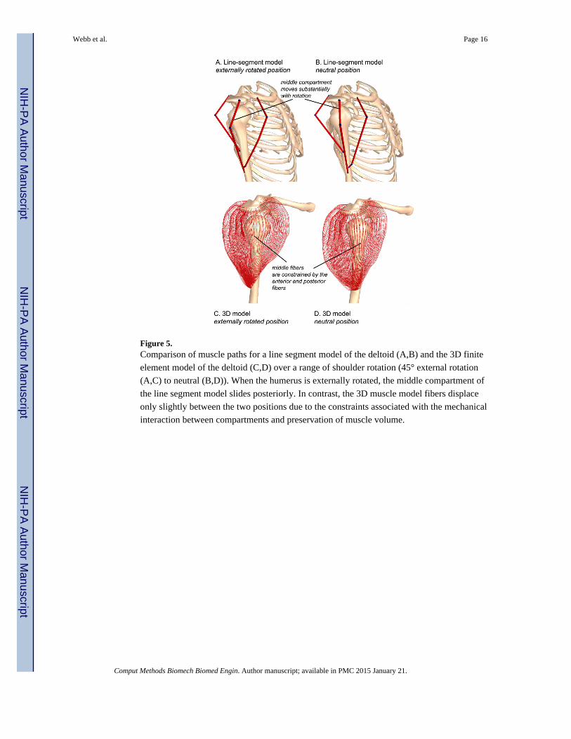
Figure 5. Comparison of muscle paths for a line segment model of the deltoid (A,B) and the 3D finite
element model of the deltoid (C,D) over a range of shoulder rotation (45° external rotation
(A,C) to neutral (B,D)). When the humerus is externally rotated, the middle compartment of
the line segment model slides posteriorly. In contrast, the 3D muscle model fibers displace
only slightly between the two positions due to the constraints associated with the mechanical
interaction between compartments and preservation of muscle volume.
Webb et al. Page 16
Comput Methods Biomech Biomed Engin. Author manuscript; available in PMC 2015 January 21.
NIH
-PA
Author M
anuscriptN
IH-P
A A
uthor Manuscript
NIH
-PA
Author M
anuscript

NIH
-PA
Author M
anuscriptN
IH-P
A A
uthor Manuscript
NIH
-PA
Author M
anuscript
Webb et al. Page 17
Table 1
Summary of the nodes and elements in the finite element model
Muscle Nodes Elements # tendon branches
Supraspinatus 26138 23610 1
Infraspinatus 21320 19119 3
Teres Minor 14358 12848 2
Subscapularis 20091 17899 6
Deltoid 15972 14088 0
Bones 7436 14860 NA
Total 105315 87564 NA
Comput Methods Biomech Biomed Engin. Author manuscript; available in PMC 2015 January 21.

NIH
-PA
Author M
anuscriptN
IH-P
A A
uthor Manuscript
NIH
-PA
Author M
anuscript
Webb et al. Page 18
Table 2
Input parameters for the transversely isotropic material model used to represent muscle and tendon
Material Parameter Muscle (Pa) Tendon (Pa) Form
Along Fiber Stretch (λ) Piecewise-quadratic Exponential W1 = f (activation, λ)
Along Fiber Shear Modulus (G1) 500 19119 W2 = G1 * φ2
Cross-Fiber Shear Modulus (G2) 500 12848 W3 = G2 * ϕ2
Bulk Modulus (K) 10E9 17899 W4 = K * [ln(J)]2
Strain Energy Density = Φ = W1 + W2 + W3 + W4
Comput Methods Biomech Biomed Engin. Author manuscript; available in PMC 2015 January 21.