NIBCO Gear Operator - Outdoor Harsh Service Maintenance
8
TECHNICAL BULLETIN Page 1 of 8 NIBCO INC. WORLD HEADQUARTERS 1516 MIDDLEBURY ST. ELKHART, IN 46516-4740 USA PHONE: 574.295.3000 FAX: 574.295.3307 WEB: www.nibco.com Review Date: 09/3/2015 Original Date: 11/1/2010 Document ID: NTB-0208-02 NIBCO Gear Operator - Outdoor Harsh Service Maintenance NIBCO Gear Operators that have long-term exposure to weather and/or harsh environmental factors, such as salt water, continuous humidity, etc., can require periodical long-term maintenance activities. Rebuilding Procedure for NIBCO Gear Operators – Outdoor Service In the event a NIBCO Gear Operator has corroded to the point where it is no longer operable, the following recommended procedure should be completed: 1. Spray WD-40 onto Top Cover Plate Bolts & Indicator Plate Bolts as shown & allow to soak. 2. Remove the two screws that hold the Position Indicator to the top of the Gear Operator. 3. Remove the four or six bolts that hold the Cover Plate to the Gear Operator Housing. 4. Spray WD-40 on each end of the hand wheel shaft and the Top Cover Plate where Segment Gear protrudes thru as shown below and allow to soak.
Transcript of NIBCO Gear Operator - Outdoor Harsh Service Maintenance

TECHNICAL BULLETIN
Page 1 of 8
N I B C O I N C .
W O R L D H E A D Q U A R T E R S
1 5 1 6 M I D D L E B U R Y S T.
E L K H A R T, I N 4 6 5 1 6 - 4 7 4 0
U S A
P H O N E : 5 7 4 . 2 9 5 . 3 0 0 0
FA X : 5 7 4 . 2 9 5 . 3 3 0 7
W E B : w w w. n i b c o . c o m
Review Date: 09/3/2015 Original Date: 11/1/2010 Document ID: NTB-0208-02
NIBCO Gear Operator - Outdoor Harsh Service Maintenance
NIBCO Gear Operators that have long-term exposure to weather and/or harsh environmental factors, such as salt water, continuous humidity, etc., can require periodical long-term maintenance activities.
Rebuilding Procedure for NIBCO Gear Operators – Outdoor Service In the event a NIBCO Gear Operator has corroded to the point where it is no longer operable, the following recommended procedure should be completed:
1. Spray WD-40 onto Top Cover Plate Bolts & Indicator Plate Bolts as shown & allow to soak. 2. Remove the two screws that hold the Position Indicator to the top of the Gear Operator.
3. Remove the four or six bolts that hold the Cover Plate to the Gear Operator Housing. 4. Spray WD-40 on each end of the hand wheel shaft and the Top Cover Plate where
Segment Gear protrudes thru as shown below and allow to soak.
TECHNICAL BULLETIN
Page 2 of 8
N I B C O I N C .
W O R L D H E A D Q U A R T E R S
1 5 1 6 M I D D L E B U R Y S T.
E L K H A R T, I N 4 6 5 1 6 - 4 7 4 0
U S A
P H O N E : 5 7 4 . 2 9 5 . 3 0 0 0
FA X : 5 7 4 . 2 9 5 . 3 3 0 7
W E B : w w w. n i b c o . c o m
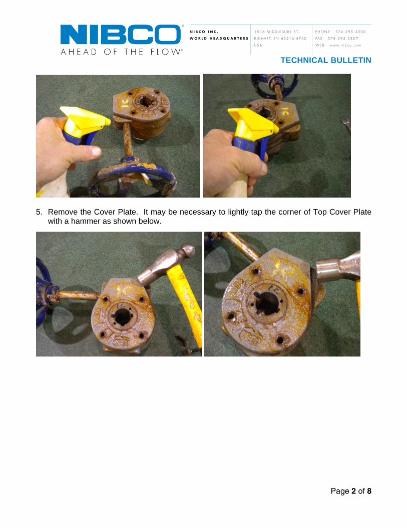
5. Remove the Cover Plate. It may be necessary to lightly tap the corner of Top Cover Plate with a hammer as shown below.

TECHNICAL BULLETIN
Page 3 of 8
N I B C O I N C .
W O R L D H E A D Q U A R T E R S
1 5 1 6 M I D D L E B U R Y S T.
E L K H A R T, I N 4 6 5 1 6 - 4 7 4 0
U S A
P H O N E : 5 7 4 . 2 9 5 . 3 0 0 0
FA X : 5 7 4 . 2 9 5 . 3 3 0 7
W E B : w w w. n i b c o . c o m
6. Rotate Top Cover Plate and pry-off Housing using a screw driver as shown above. 7. Remove Top Cover Plate and Gasket as shown above.
8. Spray generous amounts of WD-40 at each end of the Worm Gear and the Segment Gear.
For severe corrosion, it may be necessary to remove the Gear Operator from the valve and spray the bottom side of the Segment Gear as shown above.
TECHNICAL BULLETIN
Page 4 of 8
N I B C O I N C .
W O R L D H E A D Q U A R T E R S
1 5 1 6 M I D D L E B U R Y S T.
E L K H A R T, I N 4 6 5 1 6 - 4 7 4 0
U S A
P H O N E : 5 7 4 . 2 9 5 . 3 0 0 0
FA X : 5 7 4 . 2 9 5 . 3 3 0 7
W E B : w w w. n i b c o . c o m
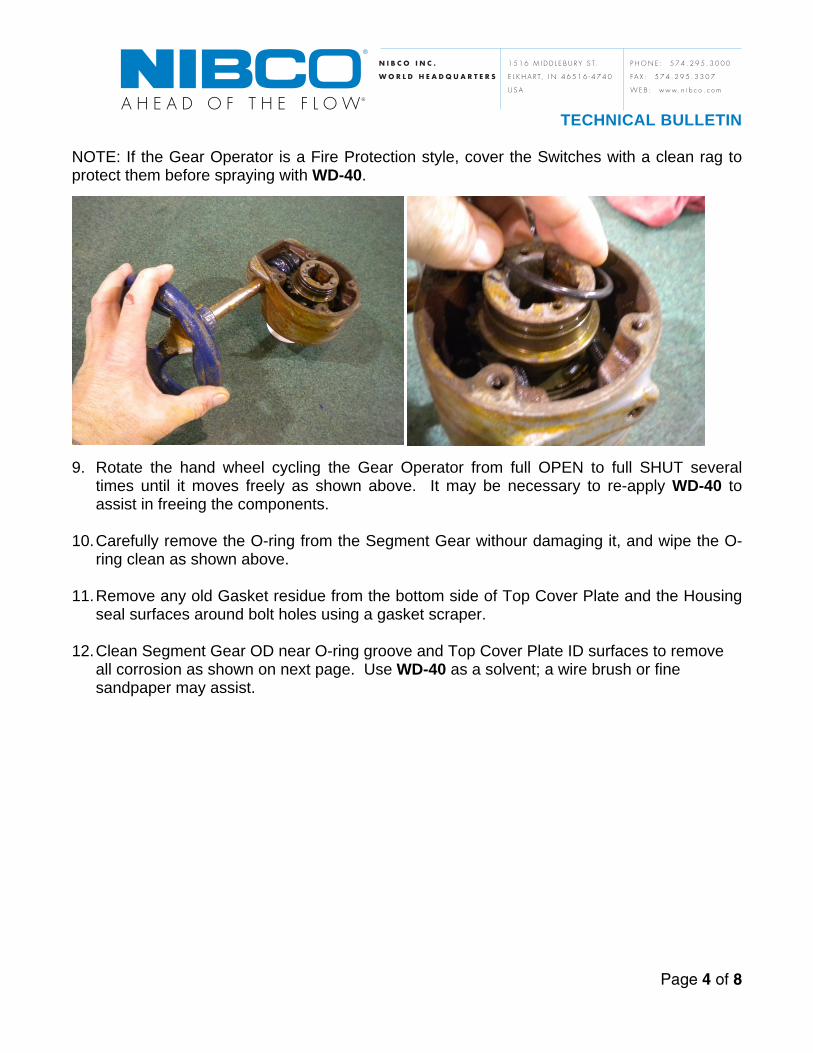
NOTE: If the Gear Operator is a Fire Protection style, cover the Switches with a clean rag to protect them before spraying with WD-40.
9. Rotate the hand wheel cycling the Gear Operator from full OPEN to full SHUT several times until it moves freely as shown above. It may be necessary to re-apply WD-40 to assist in freeing the components.
10. Carefully remove the O-ring from the Segment Gear withour damaging it, and wipe the O-
ring clean as shown above.
11. Remove any old Gasket residue from the bottom side of Top Cover Plate and the Housing seal surfaces around bolt holes using a gasket scraper.
12. Clean Segment Gear OD near O-ring groove and Top Cover Plate ID surfaces to remove
all corrosion as shown on next page. Use WD-40 as a solvent; a wire brush or fine sandpaper may assist.

TECHNICAL BULLETIN
Page 5 of 8
N I B C O I N C .
W O R L D H E A D Q U A R T E R S
1 5 1 6 M I D D L E B U R Y S T.
E L K H A R T, I N 4 6 5 1 6 - 4 7 4 0
U S A
P H O N E : 5 7 4 . 2 9 5 . 3 0 0 0
FA X : 5 7 4 . 2 9 5 . 3 3 0 7
W E B : w w w. n i b c o . c o m
13. Reinstall O-ring onto Segment Gear. Be careful not to twist the O-ring when positioning into the groove.
14. Using a good quality general purpose grease, apply a thin coating to the Segment Gear
OD, O-ring, and Top Cover Plate ID covering all mating surfaces as shown above.
NOTE: NIBCO recommends using Pennzoil Premium Wheel Bearing 707L Red or Shell Retinax LC2 or Shell LX grease.
15. Pack Worm Gear side of Gear Operator completely full of grease. Cycle hand wheel to work grease into Gear Teeth.

TECHNICAL BULLETIN
Page 6 of 8
N I B C O I N C .
W O R L D H E A D Q U A R T E R S
1 5 1 6 M I D D L E B U R Y S T.
E L K H A R T, I N 4 6 5 1 6 - 4 7 4 0
U S A
P H O N E : 5 7 4 . 2 9 5 . 3 0 0 0
FA X : 5 7 4 . 2 9 5 . 3 3 0 7
W E B : w w w. n i b c o . c o m
16. Reapply additional grease until this section of Housing is full of grease as shown below.
17. Inspect gasket for damage; if damage is present, replace paper gasket with a new one. Apply Permatex gasket sealer to both sides of Gasket as shown above.
TECHNICAL BULLETIN
Page 7 of 8
N I B C O I N C .
W O R L D H E A D Q U A R T E R S
1 5 1 6 M I D D L E B U R Y S T.
E L K H A R T, I N 4 6 5 1 6 - 4 7 4 0
U S A
P H O N E : 5 7 4 . 2 9 5 . 3 0 0 0
FA X : 5 7 4 . 2 9 5 . 3 3 0 7
W E B : w w w. n i b c o . c o m
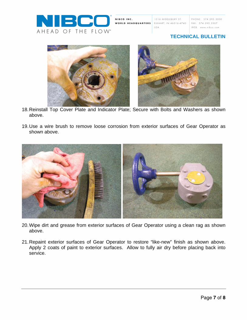
18. Reinstall Top Cover Plate and Indicator Plate; Secure with Bolts and Washers as shown
above.
19. Use a wire brush to remove loose corrosion from exterior surfaces of Gear Operator as shown above.
20. Wipe dirt and grease from exterior surfaces of Gear Operator using a clean rag as shown above.
21. Repaint exterior surfaces of Gear Operator to restore “like-new” finish as shown above.
Apply 2 coats of paint to exterior surfaces. Allow to fully air dry before placing back into service.

TECHNICAL BULLETIN
Page 8 of 8
N I B C O I N C .
W O R L D H E A D Q U A R T E R S
1 5 1 6 M I D D L E B U R Y S T.
E L K H A R T, I N 4 6 5 1 6 - 4 7 4 0
U S A
P H O N E : 5 7 4 . 2 9 5 . 3 0 0 0
FA X : 5 7 4 . 2 9 5 . 3 3 0 7
W E B : w w w. n i b c o . c o m
Touch-Up Painting Gear Operator Housings and hand wheels are painted with enamel paint. With time and exposure, the color may fade and paint may chip or flake off, requiring touch-up painting. Remove any rust or flaking paint and use the following for matching original paint colors:
Hand wheels: BLUE per PANTONE 295C Standard G/O Housings: GRAY per PANTONE # 433U UL/FM G/O Housings: RED per PANTONE # 186C UL/FM Indicator Flags: YELLOW per PANTONE # 107C
Hand wheel Shaft Galvanizing Gear Operator Shafts are nickel plated to resist corrosion, but can oxidize over time and exposure to harsher environments. As such, the shafts may need to be retreated with zinc galvanizing spray periodically.
1. To retreat the Shafts, first remove the hand wheel.
2. Remove any rust or oxidation by lightly sanding and wiping the shaft clean.
3. Recoat the Shaft using a cold-galvanizing spray (zinc rich) compound.
4. Allow the fresh coat to cure as directed by the spray compound manufacturer’s
directions before replacing the hand wheel. For additional questions regarding this or any other technical issue involving NIBCO products, please contact: NIBCO Technical Services at 1-888-446-4226