NIBCO Press System - RTCglobal.ca Press System Catalog.pdfThe NIBCO® Press System ... All valves...
64
NIBCO ® Press System ® AHEAD OF THE FLOW ® CATALOG C-NPS-0812
Transcript of NIBCO Press System - RTCglobal.ca Press System Catalog.pdfThe NIBCO® Press System ... All valves...

N I B C O® P r e s s S y s t e m®
AheAd Of the f lOw ®
Catalog C-NPS-0812

NIBCO INC. WORLD HEADQUARTERS • 1516 MIDDLEBURY ST. • ELKHART, IN 46516-4740 • USA • PH: 1.800.234.0227 TECH SERVICES PH:1.888.446.4226 • FAX: 1.888.336.4226 • INTERNATIONAL OFFICE PH: +1.574.295.3327 • FAX: +1.574.295.3455
www.nibco.com
the velocity with which e-business evolves demands that new products and serv- ices be continuously developed and introduced to keep our customers at the center of our business efforts. niBCo provides an entire suite of business-to-business solutions that is changing the way we interact with customers.
look to niBCo for technology leadership.
Business-to-Business solutions
niBCopartner.comsm is an exclusive set of secure web applications that allow quick access to customer-specific information and online order processing. this self-service approach gives you 24/7 access to your order status putting you in total control of your business.
real time information includes:• online order entry • Current price checks• Viewable invoices & reports • order status• inventory availability • online library of price sheets, catalogs & submittals
electronic Data interchange (eDi) makes it possible to trade business documents at the speed of light. this technology cuts the cost of each transaction by eliminating the manual labor and paper-work involved in traditional order taking. this amounts to cost-savings, increased accuracy and better use of resources.
With eDi, you can trade:• Purchase orders • Product activity data• Po acknowledgements • advanced ship notices• invoices • remittance advice
Vendor managed inventory (Vmi), a sophisticated service for automated inventory management, reduces your overhead by transferring inventory management, order entry and forecasting to niBCo. this is an on-going, interactive partnership with niBCo.
through automation, Vmi brings results:• improves customer service • Cuts transaction costs• optimum inventory efficiencies • Peace of mind• Better forecasting • relief from day-to-day management

NIBCO INC. WORLD HEADQUARTERS • 1516 MIDDLEBURY ST. • ELKHART, IN 46516-4740 • USA • PH: 1.800.234.0227 TECH SERVICES PH: 1.888.446.4226 • FAX: 1.888.234.0557 • INTERNATIONAL OFFICE PH: +1.574.295.3327 • FAX: +1.574.295.3455
www.nibco.com1
A H E A D O F T H E F L O W®
www.nibco.com
PageContents.......................................................................................... 1Fittings ......................................................................................... 3-9 Adapters .................................................................................... 4 Caps .......................................................................................... 4 Couplings .................................................................................. 4 Elbows ....................................................................................... 5 Fitting Reducers ........................................................................ 7 Flanges ...................................................................................... 7 Manifolds .................................................................................. 7 Tees ........................................................................................... 8 Unions ....................................................................................... 9 Accessories ............................................................................... 9Valves ...................................................................................... 10-43 Illustrated Index ................................................................ 11-12 PC585-70 Ball Valve ................................................................ 13 PC585-70-66 Ball Valve .......................................................... 14 PC585-70-NS Ball Valve w/ NIB-SEAL® Handle .................... 15 PC585-70-66-NS Ball Valve w/ NIB-SEAL® Handle ............... 16 PC585-70-LL Ball Valve w/ Locking Lever Handle ................. 17 PC585-70-66-LL Ball Valve w/ Locking Lever Handle ............ 18 PC585-70-HC Ball Valve-Hose Connection w/Cap & Chain ... 19 PC585-70-66-HC Ball Valve-Hose Connection w/Cap & Chain ...20 PC585-80-LF Lead-Free* Ball Valve ................................................21 PC585-66-LF Lead-Free* Ball Valve ................................................22 PFFP600 Ball Valve .................................................................. 23 PF111 Gate Valve .................................................................... 24 PF113 Gate Valve .................................................................... 25 PF211-Y Globe Valve ............................................................... 26 PF311-Y Angle Valve ............................................................... 27 PF413-Y Check Valve .............................................................. 28 PF480-Y In-line Check Valve ................................................... 29 PFD2000 Butterfly Valve ......................................................... 30 PS585-70 Ball Valve ................................................................ 31 PS585-70-66 Ball Valve .......................................................... 32 PS585-70-HC Ball Valve-Hose Connection w/Cap & Chain ... 33 PF221/222-A/B Bronze Y-Strainer .......................................... 34
Page Handle Options and Accessories ............................................ 35 NIB-SEAL® Technical Data ..................................................... 36 Butterfly Valve Options and Accessories ............................... 37 Butterfly Valve Technical Information .................................... 38Tools and Jaws .......................................................................39-43 NIBCO® Standard Pressing Tool - PC-280 .............................. 40 NIBCO®
Mini Pressing Tool - PC-20M .................................... 41 NIBCO® PC-10M and PC-100 Accessories ............................. 42 Approved Tool and Jaw Compatibility Matrix ....................... 43Engineering Data ................................................................... 44-47 Copper and Copper Alloy Fittings ........................................... 45 Sample Specification - Fittings .............................................. 46 Sample Specification - Valves ................................................ 47Installation Instructions ....................................................... 48-64 1/2" - 2" Fittings and Valves ................................................... 49 21/2" - 4" Fitting and Valves .................................................... 52 Testing Instructions for Leak Detection .................................. 54 Miscellaneous Technical Information..................................... 55Frequently Asked Questions ..................................................... 56
NIBCO® Press System® Fittings Warranty ............................. 57
NIBCO® Pressure Rated Metal Valves Warranty .................. 58
NIBCO® Press System®
Table of ContentsVisit our website for the most current information.
Revised 12/19/2012
*Lead Free refers to the wetted surface of pipe, fittings and fixtures in potable water systems that have a weighted average lead content ≤ 0.25% per the Safe Drinking Water Act (Sec. 1417) amended 1-4-2011 and other equivalent state regulations.

NIBCO INC. WORLD HEADQUARTERS • 1516 MIDDLEBURY ST. • ELKHART, IN 46516-4740 • USA • PH: 1.800.234.0227 TECH SERVICES PH: 1.888.446.4226 • FAX: 1.888.234.0557 • INTERNATIONAL OFFICE PH: +1.574.295.3327 • FAX: +1.574.295.3455
www.nibco.com
2
A H E A D O F T H E F L O W®
www.nibco.com
Quick and Easy
The NIBCO® Press System® is user friendly, quick and easy to install. Installation can be completed in less time than traditional solder, threaded, brazed or grooved copper systems. Significant time savings means tight budgets and deadlines are met while project delays and cost overruns are avoided.
Full System Product OfferingThe NIBCO® Press System® is more than just 1/2" to 4" fittings. Our offering also includes the industry's widest and most specified range of ball, gate, globe, angle, check and butterfly valves in addition to a full line of NIBCO® tools necessary to complete a total system installation.
Flameless
The NIBCO® Press System® is easier and safer to use because there is no flame, solder or flux required. Connections can even be made on a wet tube!
Reliable
With the NIBCO® Press System®, a watertight joint is formed between the EPDM seal and the crimped fitting or valve providing a permanent connection. Reliability you can count on ... NIBCO® Press Fittings are backed by a 107-year-old company and a 50-year written guarantee.
Approvals, Standards and Performance
The NIBCO® Press System® has undergone extensive and rigorous internal and external testing and meets various worldwide, industry and governmental standards and codes, including NSF-61, CSA and UPC. All valves and fittings are manufactured under a Quality Management System conforming to the current version of ISO-9001 standards. For a complete listing of testing criteria and results or certifica-tions and approvals please contact NIBCO Technical Services or visit www.nibco.com.
Applications
The NIBCO® Press System® can be used in new construction or repair work and is designed for potable water, HVAC and process water systems for commercial, industrial and residential applications.
Professional Appearance
The NIBCO® Press System® creates a clean joint without the mess of excess solder or discoloration.
Joint Integrity
The NIBCO® Press System® uses engineered tools, jaws and chains that are tested and approved to ensure a consistent, reliable crimp.

NIBCO INC. WORLD HEADQUARTERS • 1516 MIDDLEBURY ST. • ELKHART, IN 46516-4740 • USA • PH: 1.800.234.0227 TECH SERVICES PH: 1.888.446.4226 • FAX: 1.888.234.0557 • INTERNATIONAL OFFICE PH: +1.574.295.3327 • FAX: +1.574.295.3455
www.nibco.com3
A H E A D O F T H E F L O W®
www.nibco.com
Fittings

NIBCO INC. WORLD HEADQUARTERS • 1516 MIDDLEBURY ST. • ELKHART, IN 46516-4740 • USA • PH: 1.800.234.0227 TECH SERVICES PH: 1.888.446.4226 • FAX: 1.888.234.0557 • INTERNATIONAL OFFICE PH: +1.574.295.3327 • FAX: +1.574.295.3455
www.nibco.com
4
A H E A D O F T H E F L O W®
www.nibco.comRevised 11/16/2012
ADAPTERS
PC603 Adapter P x F – Brass Rod (*Wrot) APPROX. DIM. A NOM. SIZE NET WT./LBS. INCHES
1/2 .097 13/16
*1/2 x 3/8 .081 21/32
1/2 x 3/4 .151 31/32
3/4 .162 27/32
3/4 x 1/2 .153 25/32
1 .237 15/16
*1 x 1/2 .129 3/4
1 x 3/4 .217 13/16
*1 x 1 1/4 .436 21/4
1 1/4 .372 11/16
1 1/4 x 1 .302 11/16
*1 1/4 x 1 1/2 .602 211/32
1 1/2 .518 11/16
*1 1/2 x 3/4 .335 21/8
1 1/2 x 1 1/4 .648 1 2 .714 1 *2 1/2 1.222 113/32
*3 1.884 123/32
*4 3.238 17/8
PC617 Cap P – Wrot APPROX. DIM. N NOM. SIZE NET WT./LBS. INCHES
1/2 .046 5/32
3/4 .091 5/32
1 .125 1/8
1 1/4 .171 1/8
1 1/2 .314 3/16
2 .493 3/16
2 1/2 .476 7/32
3 .713 7/32
4 1.491 1/4
COUPLINGS
PC604 Adapter P x M – Brass Rod (*Wrot) APPROX. DIM. B NOM. SIZE NET WT./LBS. INCHES
1/2 .106 7/8
*1/2 x 3/8 .105 27/32
1/2 x 3/4 .248 11/4
3/4 .195 11/16
3/4 x 1/2 .189 31/32
1 .268 13/32
1 x 3/4 .253 11/32
1 x 1 1/4 .662 117/32
1 1/4 .467 113/32
1 1/4 x 1 .408 13/16
1 1/4 x 1 1/2 .630 11/2
1 1/2 .696 11/2
1 1/2 x 1 1/4 .670 13/8
2 .927 17/16
*2 1/2 1.322 127/32
*3 2.104 21/8
*4 3.298 29/32
PC600-DS Coupling P x P – Wrot APPROX. DIM. A NOM. SIZE NET WT./LBS. INCHES
1/2 .080 3/16
3/4 .153 5/32
1 .190 5/32
1 1/4 .250 5/32
1 1/2 .511 3/16
2 .741 3/16
2 1/2 .669 1/8
3 .979 1/8
4 1.969 7/32
PC604-P Adapter PEX x P – Wrot APPROX. DIM. B NOM. SIZE NET WT./LBS. INCHES
1/2 x 1/2 .055 1/8
1/2 x 3/4 .108 13/64
3/4 x 1/2 .150 5/64
3/4 x 3/4 .108 5/32
1 x 1 .148 11/64
CAPS
NOTE: Some items not certified by NSF to NSF/ANSI 61. See manufacturer's listing for approved sizes and applications, or contact NIBCO Technical Services for a complete listing of current certifications.

NIBCO INC. WORLD HEADQUARTERS • 1516 MIDDLEBURY ST. • ELKHART, IN 46516-4740 • USA • PH: 1.800.234.0227 TECH SERVICES PH: 1.888.446.4226 • FAX: 1.888.234.0557 • INTERNATIONAL OFFICE PH: +1.574.295.3327 • FAX: +1.574.295.3455
www.nibco.com5
A H E A D O F T H E F L O W®
www.nibco.com
PC606 45° Elbow P x P – Wrot APPROX. DIM. C DIM. D NOM. SIZE NET WT./LBS. INCHES INCHES
1/2 .092 25/64 25/64
3/4 .204 31/64 31/64
1 .251 5/8 5/8
1 1/4 .378 25/32 25/32
1 1/2 .666 7/8 7/8
2 1.096 111/64 111/64
2 1/2 1.041 29/32 29/32
3 1.536 11/8 11/8
4 3.375 111/16 111/16
COUPLINGS (Cont.)
PC600-R Reducing Coupling P x P – Wrot APPROX. DIM. A NOM. SIZE NET WT./LBS. INCHES
3/4 x 1/2 .116 11/32
1 x 1/2 .159 11/32 1 x 3/4 .184 7/16
1 1/4 x 3/4 .245 5/16
1 1/4 x 1 .231 1/2
1 1/2 x 3/4 .382 1/2
1 1/2 x 1 .370 13/32
1 1/2 x 1 1/4 .399 1/14
2 x 3/4 .516 27/32
2 x 1 .552 11/16
2 x 1 1/4 .570 11/16
2 x 1 1/2 .662 7/16
2 1/2 x 1 .594 29/32
2 1/2 x 1 1/4 .587 13/16
2 1/2 x 1 1/2 .697 11/16
2 1/2 x 2 .735 9/16
3 x 1 1/2 .938 11/32
3 x 2 1.002 31/32
3 x 2 1/2 .951 1/2
4 x 2 1.935 11/4
4 x 2 1/2 1.807 1 4 x 3 1.960 27/32
COUPLINGS (Cont.)
PC600-RS Coupling P x P – Wrot APPROX. DIM. A NOM. SIZE NET WT./LBS. INCHES
2 1/2 .688 1/16
3 .979 1/16
4 1.969 1/8
PC636 Crossover Coupling P x P – Wrot APPROX. DIM. A NOM. SIZE NET WT./LBS. INCHES
1/2 0.402 129/32
3/4 .402 21/4
PC601 (No Stop) Repair Coupling P x P – Wrot APPROX. DIM. B NOM. SIZE NET WT./LBS. INCHES
1/2 .080 13/4
3/4 .151 21/4
1 .190 21/4
1 1/4 .250 215/32
1 1/2 .511 3 11/32
2 .741 3 5/8
2 1/2 669 2 15/16
3 .979 3 5/16
4 1.878 4 5/16
ELBOWS
PC606-2 45° Elbow Ftg x P – Wrot APPROX. DIM. B DIM. C NOM. SIZE NET WT/LBS. INCHES INCHES
1/2 .086 111/32 11/32
3/4 .174 115/32 9/16
1 .248 119/32 9/16
1 1/4 .368 127/32 11/16
1 1/2 .673 23/8 7/8
2 1.098 25/8 13/32
2 1/2 1.050 23/16 29/32
3 1.526 219/32 15/32
4 3.284 33/32 11/2
NOTE: Some items not certified by NSF to NSF/ANSI 61. See manufacturer's listing for approved sizes and applications, or contact NIBCO Technical Services for a complete listing of current certifications.
Revised 11/16/2012

NIBCO INC. WORLD HEADQUARTERS • 1516 MIDDLEBURY ST. • ELKHART, IN 46516-4740 • USA • PH: 1.800.234.0227 TECH SERVICES PH: 1.888.446.4226 • FAX: 1.888.234.0557 • INTERNATIONAL OFFICE PH: +1.574.295.3327 • FAX: +1.574.295.3455
www.nibco.com
6
A H E A D O F T H E F L O W®
www.nibco.comRevised 11/16/2012
PC607-2 90° Elbow Ftg x P – Wrot APPROX. DIM. B DIM. C NOM. SIZE NET WT/LBS. INCHES INCHES
1/2 .125 123/32 25/32
3/4 .212 213/64 13/64
1 .319 21/2 113/32
1 1/4 .490 231/32 17/8
1 1/2 .871 321/32 21/4
2 1.622 415/32 215/16
2 1/2 1.356 315/32 129/32
3 2.065 313/16 23/32
4 3.920 43/4 225/32
PC607 90° Elbow P x P – Wrot APPROX. DIM. C DIM. D NOM. SIZE NET WT./LBS. INCHES INCHES
1/2 .135 13/32 13/32
3/4 .223 15/64 15/64
3/4 x 1/2 .190 13/16 11/16
1 .323 17/16 17/16
1 1/4 .554 111/16 111/16
1 1/2 .863 213/64 213/64
2 1.562 215/16 215/16
2 1/2 1.224 127/32 127/32
3 1.998 23/32 23/32
4 4.060 225/32 225/32
ELBOWS (Cont.)
PC707-3 90° Elbow P x F – Cast APPROX. DIM. C DIM. E NOM. SIZE NET WT./LBS. INCHES INCHES
3/4 x 1/2 .318 13/64 153/64
1 1/4 .901 119/32 119/32
1 1/2 1.327 119/32 111/16
2 1.327 21/4 25/32
PC707-4 90° Elbow P x M – Cast APPROX. DIM. C DIM. E NOM. SIZE NET WT./LBS. INCHES INCHES
1/2 .263 11/8 123/32
1 .714 111/32 213/16
1 1/4 1.273 113/16 31/2
PC607-2-LT 90° Long Radius Elbow Ftg x P - Wrot APPROX. DIM. B DIM. C NOM. SIZE NET WT/LBS. INCHES INCHES
2 1/2 2.114 57/32 311/16
3 3.037 53/4 41/32
PC607-3 90° Elbow P x F - Wrot APPROX. DIM. A DIM. C NOM. SIZE NET WT/LBS. INCHES INCHES
1/2 .213 213/16 13/32
3/4 .361 321/64 13/64
1/2 x 3/8 .148 21/4 25/32
1/2 x 3/4 .243 213/16 13/64
1 .513 315/32 113/32
PC607-4 90° Elbow P x M - Wrot APPROX. DIM. B DIM. C NOM. SIZE NET WT/LBS. INCHES INCHES
1/2 x 3/4 .245 211/16 25/32
3/4 .373 31/64 13/64
3/4 x 1/2 .340 33/64 13/64
1 1/2 1.433 431/32 29/32
2 2.080 621/32 259/64
PC607-LT 90° Long Radius Elbow P x P – Wrot APPROX. DIM. C DIM. D NOM. SIZE NET WT/LBS. INCHES INCHES
2 1/2 2.066 311/16 311/16
3 3.037 41/32 41/32
4 5.696 51/4 51/4
NOTE: Some items not certified by NSF to NSF/ANSI 61. See manufacturer's listing for approved sizes and applications, or contact NIBCO Technical Services for a complete listing of current certifications.

NIBCO INC. WORLD HEADQUARTERS • 1516 MIDDLEBURY ST. • ELKHART, IN 46516-4740 • USA • PH: 1.800.234.0227 TECH SERVICES PH: 1.888.446.4226 • FAX: 1.888.234.0557 • INTERNATIONAL OFFICE PH: +1.574.295.3327 • FAX: +1.574.295.3455
www.nibco.com7
A H E A D O F T H E F L O W®
www.nibco.com
Cont. next page
PC695 1-Outlet Manifold P x Ftg x P - Wrot APPROX. DIMENSIONS NET WT. INCHES NOM. SIZE LBS. B C F
1 x 1 x 1/2 .504 115/16 11/8 15/16
PC696 3-Outlet Manifold P x Ftg x P - Wrot APPROX. DIMENSIONS NET WT. INCHES NOM. SIZE LBS. B C E F
1 x 1 x 1/2 .882 121/32 3/4 131/32 63/8
MANIFOLDS
PC641 Companion Flange P x Flange - Wrot APPROX. DIMENSIONS NET WT. INCHES NOM. SIZE LBS. A B C
2 1/2 6.177 19/32 225/32 5/8
3 7.554 3/4 215/16 21/32
4 11.211 29/32 33/8 27/32
FLANGES
PC741 Companion Flange P x Flange - Bronze Flange/Wrot Outlet APPROX. DIMENSIONS NET WT. INCHES NOM. SIZE LBS. B F G W
1 1.419 15/32 41/4 1/4 31/8
1 1/4 1.632 15/16 45/8 1/4 31/2
1 1/2 2.186 17/16 5 5/16 37/8
2 3.352 111/16 6 3/8 43/4
NOTE: 4" requires (8) "G" holes equally spaced.NOTE: Mates with ANSI Class 125/150 flanges.
NOTE: Some items not certified by NSF to NSF/ANSI 61. See manufacturer's listing for approved sizes and applications, or contact NIBCO Technical Services for a complete listing of current certifications.
DIMENSIONS INCHES NOM. SIZE D E F G
2 1/2 3/4 51/2 7 3/4
3 13/16 6 71/2 3/4
4 1 7 1/2 9 3/4
*See online catalog at www.nibco.com
PC600-2 Fitting Reducer Ftg x P – Wrot APPROX. DIM. A NOM. SIZE NET WT/LBS. INCHES
3/4 x 1/2 .108 13/8
1 x 1/2 .133 115/32
1 x 3/4 .167 11/32
1 1/4 x 3/4 .211 5/16
1 1/4 x 1 .191 115/32
1 1/2 x 1/2 .242 37/64
1 1/2 x 3/4 .298 15/32
1 1/2 x 1 .294 113/16
1 1/2 x 1 1/4 .311 13/4
2 x 1/2 .443 21/4
2 x 3/4 .470 3/4
2 x 1 .433 27/32
2 X 1 1/4 .459 115/16
2 x 1 1/2 .543 17/8
2 1/2 x 1 .507 211/32
2 1/2 x 1 1/4 .658 29/32
2 1/2 x 1 1/2 .806 213/32
2 1/2 x 2 .810 131/32
3 x 1 1/4 .882 39/32
3 x 1 1/2 .812 25/8
3 x 2 1.041 29/16
3 x 2 1/2 .820 21/4
4 x 2 1.670 313/32
4 x 2 1/2 1.837 31/32
4 x 3 2.013 31/32
FITTING REDUCERS
ELBOWS (Cont.)
PC707-3-5 90° Drop Elbow P x F – Cast APPROX. DIMENSIONS NET WT. INCHES NOM. SIZE LBS. A C E
1/2 .172 17/32 7/8 27/32
3/4 .316 11/16 11/4 31/32
Revised 11/16/2012

NIBCO INC. WORLD HEADQUARTERS • 1516 MIDDLEBURY ST. • ELKHART, IN 46516-4740 • USA • PH: 1.800.234.0227 TECH SERVICES PH: 1.888.446.4226 • FAX: 1.888.234.0557 • INTERNATIONAL OFFICE PH: +1.574.295.3327 • FAX: +1.574.295.3455
www.nibco.com
8
A H E A D O F T H E F L O W®
www.nibco.comRevised 11/16/2012
2 x 1 1/2 x 3/4 1.542 113/32 111/16 27/32
2 x 1 1/2 x 1 1.546 113/32 123/32 23/32
2 x 1 1/2 x 1 1/4 1.543 113/32 111/16 21/16
2 x 1 1/2 x 1 1/2 1.670 113/32 123/32 123/32
2 x 2 x 1/2 1.576 113/32 113/32 25/16
2 x 2 x 3/4 1.573 113/32 113/32 29/32
2 x 2 x 1 1.633 113/32 113/32 27/32
2 x 2 x 1 1/4 1.576 113/32 113/32 131/32
2 x 2 x 1 1/2 1.770 11/8 11/8 17/16
2 1/2 2.082 15/8 15/8 15/8
2 1/2 x 3/4 x 2 1/2 2.296 19/16 23/16 17/8
2 1/2 x 1 x 2 1/2 2.297 19/16 219/32 17/8
2 1/2 x 1 1/4 x 2 1/2 2.202 19/16 219/32 17/8
2 1/2 x 1 1/2 x 2 1/2 2.223 19/16 21/4 17/8
2 1/2 x 2 x 3/4 2.233 19/16 21/4 229/32
2 1/2 x 2 x 1 2.090 19/16 21/4 219/32
2 1/2 x 2 x 1 1/4 2.151 19/16 21/4 29/16
2 1/2 x 2 x 1 1/2 2.155 19/16 21/4 25/8
2 1/2 x 2 x 2 2.694 19/16 21/4 21/4
2 1/2 x 2 x 2 1/2 2.282 19/16 21/32 17/8
2 1/2 x 2 1/2 x 1/2 2.296 19/16 19/16 31/16
2 1/2 x 2 1/2 x 3/4 2.029 19/16 19/16 31/16
2 1/2 x 2 1/2 x 1 2.089 19/16 19/16 29/16
2 1/2 x 2 1/2 x 1 1/4 2.066 19/16 19/16 25/8
2 1/2 x 2 1/2 x 1 1/2 2.078 19/16 19/16 25/8
2 1/2 x 2 1/2 x 2 2.531 19/16 19/16 27/32
3 3.122 17/8 17/8 21/32
3 x 3/4 x 3 3.136 113/16 31/4 23/16
3 x 1 x 3 3.146 113/16 39/32 23/16
3 x 1 1/4 x 3 3.070 113/16 27/8 23/16
3 x 1 1/2 x 3 3.110 113/16 215/16 23/16
3 x 2 x 2 3.158 113/16 213/16 225/32
3 x 2 x 2 1/2 3.089 113/16 213/16 21/2
3 x 2 x 3 3.164 113/16 211/16 23/16
3 x 2 1/2 x 2 3.153 113/16 215/32 225/32
3 x 2 1/2 x 2 1/2 3.010 113/16 215/32 21/2
3 x 2 1/2 x 3 3.194 113/16 215/32 23/16
3 x 3 x 1/2 2.891 113/16 113/16 33/8
3 x 3 x 3/4 2.462 113/16 113/16 313/32
TEES
APPROX. DIMENSIONS NET WT. INCHES NOM. SIZE LBS. C F G
APPROX. DIMENSIONS NET WT. INCHES NOM. SIZE LBS. C F G
3 x 3 x 1 2.978 113/16 113/16 31/4
3 x 3 x 1 1/4 2.963 113/16 113/16 215/16
3 x 3 x 1 1/2 3.006 113/16 113/16 3 3 x 3 x 2 3.113 113/16 113/16 215/32
3 x 3 x 2 1/2 3.034 129/32 129/32 23/8
4 7.169 213/32 213/32 217/32
4 x 2 x 4 7.332 23/8 41/32 223/32
4 x 2 1/2 x 4 6.984 23/8 325/32 223/32
4 x 3 x 2 7.160 23/8 39/16 33/4
4 x 3 x 2 1/2 6.990 23/8 39/16 329/32
4 x 3 x 3 7.085 23/8 39/16 31/2
4 x 3 x 4 6.993 23/8 323/32 223/32
4 x 4 x 1/2 6.770 23/8 23/8 415/32
4 x 4 x 3/4 6.756 23/8 23/8 41/8
4 x 4 x 1 6.929 23/8 23/8 45/32
4 x 4 x 1 1/4 6.902 23/8 23/8 41/32
4 x 4 x 1 1/2 7.099 23/8 23/8 33/4
4 x 4 x 2 7.072 23/8 23/8 315/16
4 x 4 x 2 1/2 6.925 23/8 23/8 329/32
4 x 4 x 3 7.083 23/8 23/8 31/2
PC611 Tee P x P x P – Wrot APPROX. DIMENSIONS NET WT. INCHES NOM. SIZE LBS. C F G
1/2 .182 11/16 11/16 15/32
1/2 x 1/2 x 3/4 .261 13/16 13/`16 5/8
1/2 x 1/2 x 1 .491 17/32 17/32 63/64
3/4 .340 23/32 23/32 5/8
3/4 x 1/2 x 1/2 .329 23/32 13/16 11/16
3/4 x 1/2 x 3/4 .333 23/32 13/16 5/8
3/4 x 3/4 x 1/2 .339 23/32 23/32 11/16
3/4 x 3/4 x 1 .461 13/32 13/32 29/32
1 .486 7/8 7/8 29/32
1 x 1/2 x 1 .513 15/16 13/16 29/32
1 x 3/4 x 1/2 .368 7/8 13/32 13/16
1 x 3/4 x 3/4 .465 7/8 13/32 11/16
1 x 3/4 x 1 .521 7/8 11/8 29/32
1 x 1 x 1/2 .457 7/8 7/8 17/32
1 x 1 x 3/4 .480 27/32 27/32 11/16
1 x 1 x 1 1/4 .723 17/32 17/32 29/32
1 1/4 .714 1 1 29/32
1 1/4 x 1 x 3/4 .753 1 17/32 13/8
1 1/4 x 1 x 1 .725 1 19/64 117/64
1 1/4 x 1 1/4 x 1/2 .747 1 1 17/16
1 1/4 x 1 1/4 x 3/4 .767 1 1 13/8
1 1/4 x 1 1/4 x 1 .690 1 1 1 1/4
1 1/2 1.179 15/16 15/16 13/32
1 1/2 x 1/2 x 1 1/2 1.227 31/32 17/8 1 1 1/2 x 3/4 x 3/4 1.101 61/64 155/64 113/16
1 1/2 x 1 x 3/4 1.101 61/64 111/16 113/16
1 1/2 x 1 x 1 1.105 1 147/64 141/64
1 1/2 x 1 x 1 1/2 1.146 31/32 15/8 1 1 1/2 x 1 1/4 x 1 1.105 61/64 141/64 15/8
1 1/2 x 1 1/4 x 1 1/4 1.160 31/32 17/16 115/32
1 1/2 x 1 1/2 x 1/2 1.209 15/16 15/16 131/32
1 1/2 x 1 1/2 x 3/4 1.070 15/16 15/16 113/16
1 1/2 x 1 1/2 x 1 1.074 15/16 15/16 1 19/32
1 1/2 x 1 1/2 x 1 1/4 1.166 61/64 61/64 111/16
2 1.771 113/32 113/32 113/32
2 x 1/2 x 2 1.663 113/32 23/8 113/32
2 x 1 x 1 1.764 123/64 21/4 27/32
2 x 1 x 2 1.564 113/32 27/32 127/32
2 x 1 1/4 x 1 1/4 1.471 113/32 127/32 17/8

NIBCO INC. WORLD HEADQUARTERS • 1516 MIDDLEBURY ST. • ELKHART, IN 46516-4740 • USA • PH: 1.800.234.0227 TECH SERVICES PH: 1.888.446.4226 • FAX: 1.888.234.0557 • INTERNATIONAL OFFICE PH: +1.574.295.3327 • FAX: +1.574.295.3455
www.nibco.com9
A H E A D O F T H E F L O W®
www.nibco.com
TEES (Cont.) UNIONS (Cont.) ACCESSORIES
EPDM Seal PART SIZE No.
1/2 T048052 3/4 T048054 1 T048056 1 1/4 T048058 1 1/2 T048060 2 T048062 2 1/2 T048064 3 T048066 4 T048070
PC612 Tee P x P x F – Wrot APPROX. DIMENSIONS NET WT. INCHES NOM. SIZE LBS. E F G
1/2 .266 131/32 11/16 11/16
3/4 x 3/4 x 1/2 .423 25/8 23/32 23/32
1 x 1 x 1/2 .541 211/16 7/8 7/8
1 x 1 x 3/4 .673 227/32 27/32 27/32
1 1/4 x 1 1/4 x 1/2 .832 27/8 1 1 1 1/4 x 1 1/4 x 3/4 .922 31/16 1 1 1 1/2 x 1 1/2 x 1/2 1.141 319/64 15/16 15/16
1 1/2 x 1 1/2 x 3/4 1.291 33/8 31/32 31/32
2 x 2 x 1/2 1.699 313/16 1 13/32 1 13/32
2 x 2 x 3/4 1.693 331/32 113/32 113/32
2 1/2 x 2 1/2 x 3/4 1.049 215/32 11/16 11/16
2 1/2 x 2 1/2 x 2 1.925 37/32 19/32 19/32
3 x 3 x 3/4 1.435 23/4 11/16 11/16
3 x 3 x 2 2.097 315/32 19/32 19/32
4 x 4 x 3/4 2.786 31/4 11/16 11/16
4 x 4 x 2 3.675 4 19/32 19/32
UNIONS
PC733-3 Union P x F – Brass Rod APPROX. DIM. A NOM. SIZE NET WT./LBS. INCHES
1 1/4 1.098 159/64
1 1/2 1.885 155/64
PC633-3 Union P x F – Wrot APPROX. DIM. A NOM. SIZE NET WT./LBS. INCHES
1/2 .374 17/16
3/4 .559 117/32
1 .918 139/64
2 2.445 211/64
PC633 Union P x P – Wrot APPROX. DIM. A NOM. SIZE NET WT./LBS. INCHES
1/2 .383 15/16 3/4 .590 19/32
1 .850 111/32
1 1/4 1.126 137/64
1 1/2 1.723 15/8
2 2.627 127/32
PC733-4 Union P x M – Brass Rod APPROX. DIM. A NOM. SIZE NET WT./LBS. INCHES
1 1/4 1.269 225/64
PC633-4 Union P x M – Wrot APPROX. DIM. A NOM. SIZE NET WT./LBS. INCHES
1/2 .397 113/16
3/4 .574 129/32
1 .904 25/32
1 1/2 1.769 211/32
2 2.789 249/64
EPDM Seal (leak detection) PART SIZE No.
1/2 T048352 3/4 T048354 1 T048356 1 1/4 T048358 1 1/2 T048360 2 T048362
Revised 11/16/2012

NIBCO INC. WORLD HEADQUARTERS • 1516 MIDDLEBURY ST. • ELKHART, IN 46516-4740 • USA • PH: 1.800.234.0227 TECH SERVICES PH: 1.888.446.4226 • FAX: 1.888.234.0557 • INTERNATIONAL OFFICE PH: +1.574.295.3327 • FAX: +1.574.295.3455
www.nibco.com
10
A H E A D O F T H E F L O W®
www.nibco.com
Valves

NIBCO INC. WORLD HEADQUARTERS • 1516 MIDDLEBURY ST. • ELKHART, IN 46516-4740 • USA • PH: 1.800.234.0227 TECH SERVICES PH: 1.888.446.4226 • FAX: 1.888.234.0557 • INTERNATIONAL OFFICE PH: +1.574.295.3327 • FAX: +1.574.295.3455
www.nibco.com11
A H E A D O F T H E F L O W®
www.nibco.com
NIBCO® Press System®
Illustrated Valve IndexPC585-70
PC585-70-66Bronze Ball Valve
•PressxPressFemaleEnd•FullPort,Blowout-ProofStem•StandardLeverHandle•250PSICWP•Sizes1/2"thru2"
Page 13, 14
PC585-70-NSPC585-70-66-NS
Bronze Ball Valve
•PressFemaleEndxHose•FullPort,Blowout-ProofStem•NIB-SEAL® Handle•250PSICWP•Sizes1/2"thru2"
Page 15, 16
PC585-70-LLPC585-70-66-LL
Bronze Ball Valve
•PressxPressFemaleEnd•FullPort,Blowout-ProofStem•LockingLeverHandle•250PSICWP•Sizes1/2"thru2"
Page 17, 18
PC585-70-HCPC585-70-66-HC
Bronze Ball Valve
•PressFemaleEndxHose•FullPort,Blowout-ProofStem•StandardLeverHandle•BlowDown,EndofLine•HoseCapwithChain•250PSICWP•Sizes1/2"and3/4"
Page 19, 20
PFFP-600Brass Ball Valve
•PressxPressFemaleEnd•FullPort,Blowout-ProofStem•StandardLeverHandle•600PSICWP•Sizes1/2"thru2"
Page 23
PF111Bronze Gate Valve
•PressxPressFemaleEnd•RisingStem•200PSICWP•Sizes1/2"thru2"
Page 24
PF113Bronze Gate Valve
•PressxPressFemaleEnd•Non-RisingStem•200PSICWP•Sizes1/2"thru2"
Page 25
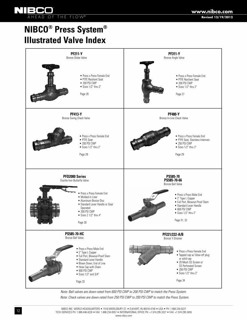
Note: Ball valves are down-rated from 600 PSI CWP to 200 PSI CWP to match the Press System.
Revised 8/7/2012
PC585-80-LFPC585-66-LFBronze Ball Valve
•Lead-Free*•PressxPressFemaleEnd•FullPort,Blowout-ProofStem•StandardLeverHandle•250PSICWP•Sizes1/2"thru2"
Page 21, 22
*Lead Free refers to the wetted surface of pipe, fittings and fixtures in potable water systems that have a weighted average lead content ≤ 0.25% per the Safe Drinking Water Act (Sec. 1417) amended 1-4-2011 and other equivalent state regulations.
NIBCO INC. WORLD HEADQUARTERS • 1516 MIDDLEBURY ST. • ELKHART, IN 46516-4740 • USA • PH: 1.800.234.0227 TECH SERVICES PH: 1.888.446.4226 • FAX: 1.888.234.0557 • INTERNATIONAL OFFICE PH: +1.574.295.3327 • FAX: +1.574.295.3455
www.nibco.com
12
A H E A D O F T H E F L O W®
www.nibco.com
NIBCO® Press System®
Illustrated Valve IndexPF311-Y
Bronze Angle Valve
•PressxPressFemaleEnd•PTFEResilientSeat•200PSICWP•Sizes1/2"thru2"
Page 27
PF413-YBronze Swing Check Valve
•PressxPressFemaleEnd•PTFESeat•200PSICWP•Sizes1/2"thru2"
Page 28
PF480-YBronze In-Line Check Valve
•PressxPressFemaleEnd•PTFESeat,StainlessInternals•250PSICWP•Sizes1/2"thru2"
Page 29
Note: Ball valves are down-rated from 600 PSI CWP to 200 PSI CWP to match the Press System.
PS585-70PS585-70-66Bronze Ball Valve
•PressxPressMaleEnd•2"TypeLCopper•FullPort,Blowout-ProofStem•StandardLeverHandle•600PSICWP•Sizes1/2"thru2"
Page 31, 32
PS585-70-HCBronze Ball Valve
•PressxPressMaleEnd•2"TypeLCopper•FullPort,Blowout-ProofStem•StandardLeverHandle•BlownDown,EndofLine•HoseCapwithChain•600PSICWP•Sizes1/2"and3/4"
Page 33
PFD2000 SeriesDuctile Iron Butterfly Valve
•PressxPressFemaleEnd•Molded-inLiner•AluminumBronzeDisc•StandardLeverHandleorGear
Operated•200PSICWP•Sizes21/2"thru4"
Page 30
Note: Check valves are down-rated from 250 PSI CWP to 200 PSI CWP to match the Press System.
PF221/222-A/BBronze Y-Strainer
•PressxPressFemaleEnd•Tappedcapw/blow-offplug
or solid cap•20MeshSSScreenor
SS Perforated Screen•200PSICWP•Sizes1/2"thru2"
Page 34
Revised 12/19/2012
PF211-YBronze Globe Valve
•PressxPressFemaleEnd•PTFEResilientSeat•200PSICWP•Sizes1/2"thru2"
Page 26

NIBCO INC. WORLD HEADQUARTERS • 1516 MIDDLEBURY ST. • ELKHART, IN 46516-4740 • USA • PH: 1.800.234.0227 TECH SERVICES PH: 1.888.446.4226 • FAX: 1.888.234.0557 • INTERNATIONAL OFFICE PH: +1.574.295.3327 • FAX: +1.574.295.3455
www.nibco.com13
A H E A D O F T H E F L O W®
www.nibco.com
Note: Check valves are down-rated from 250 PSI CWP to 200 PSI CWP to match the Press System.
DezincificationResistant
NIBCO® Press System® Bronze Ball Valves Two-PieceBody•FullPort•BronzeTrim•Blowout-ProofStem
250 PSI/17.2 Bar Non-Shock Cold Working Pressure250°F Maximum Operating Temperature
CONFORMS TO MSS SP-110
MATERIAL LIST PART SPECIFICATION 1. Body Bronze ASTM B584 Alloy C84400 2. Body End Bronze ASTM B584 Alloy C84400 3. Press End Adapter (2) Bronze ASTM B61 Alloy C92200 4. Ball Brass ASTM B16 Alloy C36000 or ASTM B283 Alloy C37700 (Chrome/Nickel Plated) 5. Seat Ring (2) Reinforced PTFE 6. Boss seal o-ring (2) EPDM 7. O-Ring (2) EPDM 8. Packing PTFE 9. Pack Gland Brass ASTM B16 Alloy C36000 10. Stem Silicon Bronze ASTM B371 Alloy C69430 or ASTM B371 Alloy C69430 11. Handle Nut Zinc Plated Steel 12. Thrust Washer Reinforced PTFE 13. Handle Assembly Zinc Plated Steel with Plastisol Coating
PC585-70P x P
NIBCO® Press System® ball valves are designed to meet MSS SP-110 with the exception of the end connection. Ball valves are down-rated from 600 PSI CWP to 250 PSI CWP to match the Press System®. Male and female press-to-connect ends are new technology not yet covered in the current edition of this specification.
PC585-70Press x Press Female End
DimensionsSIZE A B C D E Weight
In. mm. In. mm. In. mm. In. mm. In. mm. In. mm. Lbs. Kg.
1/2” 13 2.76 70 1.90 48 6.00 152 .50 13 4.15 105 .80 .36
3/4” 19 3.28 83 2.28 58 7.29 185 .75 19 5.05 128 1.56 .711” 25 3.59 91 2.41 61 7.34 186 1.00 25 5.36 136 2.13 1.00
11/4” 32 4.62 117 3.05 77 10.04 255 1.25 32 6.64 169 3.73 1.6911/2” 38 5.23 133 3.30 84 10.72 272 1.50 38 8.00 203 5.53 2.512” 50 5.63 143 3.51 89 11.05 281 2.00 50 8.65 220 7.95 3.61
DIMENSIONS—WEIGHTS
Revised 8/7/2012

NIBCO INC. WORLD HEADQUARTERS • 1516 MIDDLEBURY ST. • ELKHART, IN 46516-4740 • USA • PH: 1.800.234.0227 TECH SERVICES PH: 1.888.446.4226 • FAX: 1.888.234.0557 • INTERNATIONAL OFFICE PH: +1.574.295.3327 • FAX: +1.574.295.3455
www.nibco.com
14
A H E A D O F T H E F L O W®
www.nibco.com
NIBCO® Press System® Bronze Ball Valves
PC585-70-66P x P
DezincificationResistantTwo-PieceBody•FullPort•StainlessTrim•Blowout-ProofStem•VentedBall
250 PSI/17.2 Bar Non-Shock Cold Working Pressure250°F Maximum Operating Temperature
CONFORMS TO MSS SP-110
PC585-70-66Press x PressFemale End
MATERIAL LIST PART SPECIFICATION 1. Body Bronze ASTM B584 Alloy C84400 2. Body End Bronze ASTM B584 Alloy C84400 3. Female Adapter (2) Bronze ASTM B61 Alloy C92200 4. Ball (vented) Stainless Steel ASTM A276 Type 316 or ASTM A351 Type CF8M 5. Seat Ring (2) Reinforced PTFE 6. Boss Seal O-Ring (2) EPDM 7. O-Ring (2) EPDM 8. Packing PTFE 9. Pack Gland Brass ASTM B16 Alloy C36000 10. Stem Stainless Steel ASTM A276 Type 316 11. Handle Nut 300 Series Stainless Steel 12. Thrust Washer Reinforced PTFE 13. Handle Assembly Zinc Plated Steel with Plastisol Coating
NIBCO® Press System® ball valves are designed to meet MSS SP-110 with the exception of the end connection. Ball valves are down-rated from 600 PSI CWP to 250 PSI CWP to match the Press System®. Male and female press-to-connect ends are new technology not yet covered in the current edition of this specification.
DimensionsSIZE A B C D E Weight
In. mm. In. mm. In. mm. In. mm. In. mm. In. mm. Lbs. Kg.
1/2” 13 2.76 70 1.90 48 6.00 152 .50 13 4.15 105 .77 .35
3/4” 19 3.28 83 2.28 58 7.29 185 .75 19 5.05 128 1.55 .701” 25 3.59 91 2.40 61 7.34 186 1.00 25 5.36 136 2.29 1.04
11/4” 32 4.62 117 3.05 77 10.04 255 1.25 32 6.64 169 3.80 1.7211/2” 38 5.23 133 3.30 84 10.72 272 1.50 38 8.00 203 5.60 2.542” 50 5.63 143 3.51 89 11.05 281 2.00 50 8.65 220 8.69 3.94
DIMENSIONS—WEIGHTS
Revised 8/7/2012
NIBCO INC. WORLD HEADQUARTERS • 1516 MIDDLEBURY ST. • ELKHART, IN 46516-4740 • USA • PH: 1.800.234.0227 TECH SERVICES PH: 1.888.446.4226 • FAX: 1.888.234.0557 • INTERNATIONAL OFFICE PH: +1.574.295.3327 • FAX: +1.574.295.3455
www.nibco.com15
A H E A D O F T H E F L O W®
www.nibco.com
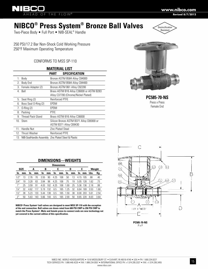
NIBCO® Press System® Bronze Ball Valves Two-PieceBody•FullPort•NIB-SEAL® Handle
250 PSI/17.2 Bar Non-Shock Cold Working Pressure250°F Maximum Operating Temperature
PC585-70-NSPress x Press Female End
PC585-70-NSP x P
1. Body Bronze ASTM B584 Alloy C84000 2. Body End Bronze ASTM B584 Alloy C84400 3. Female Adapter (2) Bronze ASTM B61 Alloy C92200 4. Ball Brass ASTM B16 Alloy C36000 or ASTM B283 Alloy C37700 (Chrome/Nickel Plated) 5. Seat Ring (2) Reinforced PTFE 6. Boss Seal O-Ring (2) EPDM 7. O-Ring (2) EPDM 8. Packing PTFE 9. Thread Pack Gland Brass ASTM B16 Alloy C36000 10. Stem Silicon Bronze ASTM B371 Alloy C69300 or ASTM B371 Alloy C69430 11. Handle Nut Zinc Plated Steel 12. Thrust Washer Reinforced PTFE 13. NIB-SealHandle Assembly Zinc Plated Steel & Plastic
MATERIAL LIST PART SPECIFICATION
DezincificationResistant
CONFORMS TO MSS SP-110
NIBCO® Press System® ball valves are designed to meet MSS SP-110 with the exception of the end connection. Ball valves are down-rated from 600 PSI CWP to 250 PSI CWP to match the Press System®. Male and female press-to-connect ends are new technology not yet covered in the current edition of this specification.
DimensionsSIZE A B C D E Weight
In. mm. In. mm. In. mm. In. mm. In. mm. In. mm. Lbs. Kg.
1/2” 13 2.76 70 3.55 90 4.25 108 .50 13 4.15 105 .88 .40
3/4” 19 3.28 83 3.84 98 4.25 108 .75 19 5.05 128 1.62 .731” 25 3.59 91 4.03 102 4.25 108 1.00 25 5.36 136 2.18 .99
11/4” 32 4.62 117 5.19 132 6.5 165 1.25 32 6.64 169 3.53 1.6011/2” 38 5.23 133 5.44 138 6.5 165 1.50 38 8.00 203 5.61 2.542” 50 5.63 143 5.66 144 6.5 165 2.00 50 8.65 220 8.03 3.64
DIMENSIONS—WEIGHTS
Revised 8/7/2012

NIBCO INC. WORLD HEADQUARTERS • 1516 MIDDLEBURY ST. • ELKHART, IN 46516-4740 • USA • PH: 1.800.234.0227 TECH SERVICES PH: 1.888.446.4226 • FAX: 1.888.234.0557 • INTERNATIONAL OFFICE PH: +1.574.295.3327 • FAX: +1.574.295.3455
www.nibco.com
16
A H E A D O F T H E F L O W®
www.nibco.com
NIBCO® Press System® Bronze Ball Valves Two-PieceBody•FullPort•316SSBall&Stem•NIB-SEAL®Handle•VentedBall
250 PSI/17.2 Bar Non-Shock Cold Working Pressure250°F Maximum Operating Temperature
PC585-70-66-NSPress x Press Female End
PC585-70-66-NSP x P
DezincificationResistant
CONFORMS TO MSS SP-110
NIBCO® Press System® ball valves are designed to meet MSS SP-110 with the exception of the end connection. Ball valves are down-rated from 600 PSI CWP to 250 PSI CWP to match the Press System®. Male and female press-to-connect ends are new technology not yet covered in the current edition of this specification.
1. Body Bronze ASTM B584 Alloy C84400 2. Body End Bronze ASTM B584 Alloy C84400 3. Female Adapter (2) Bronze ASTM B61 Alloy C92200 4. Ball (vented) ASTM A276 Type 316 Stainless Steel or ASTM A351 Type CF8M 5. Seat Ring (2) Reinforced PTFE 6. Boss Seal O-Ring (2) EPDM 7. O-Ring (2) EPDM 8. Packing PTFE 9. Pack Gland Brass ASTM B16 Alloy C36000 10. Stem ASTM A276 Alloy Type 316 Stainless Steel 11. Handle Nut 300 Series Stainless Steel 12. Thrust Washer Reinforced PTFE 13. NIB-SealHandle Assembly Zinc Plated Steel & Plastic
MATERIAL LIST PART SPECIFICATION
CONFORMS TO MSS SP-110
DimensionsSIZE A B C D E Weight
In. mm. In. mm. In. mm. In. mm. In. mm. In. mm. Lbs. Kg.
1/2” 13 2.76 70 3.55 90 4.25 108 .50 13 4.15 105 .90 .41
3/4” 19 3.28 83 3.84 98 4.25 108 .75 19 5.05 128 1.60 .731” 25 3.59 91 4.03 102 4.25 108 1.00 25 5.36 136 2.34 1.06
11/4” 32 4.62 117 5.19 132 6.50 165 1.25 32 6.69 169 3.88 1.7611/2” 38 5.23 133 5.44 138 6.50 165 1.50 38 8.00 205 5.68 2.582” 50 5.63 143 5.66 144 6.50 165 2.00 50 8.65 220 8.77 3.98
DIMENSIONS—WEIGHTS
Revised 8/7/2012

NIBCO INC. WORLD HEADQUARTERS • 1516 MIDDLEBURY ST. • ELKHART, IN 46516-4740 • USA • PH: 1.800.234.0227 TECH SERVICES PH: 1.888.446.4226 • FAX: 1.888.234.0557 • INTERNATIONAL OFFICE PH: +1.574.295.3327 • FAX: +1.574.295.3455
www.nibco.com17
A H E A D O F T H E F L O W®
www.nibco.com
DezincificationResistant
NIBCO® Press System® Bronze Ball Valves Two-PieceBody•FullPort•BronzeTrim•Blowout-ProofStem•LockingHandle
250 PSI/17.2 Bar Non-Shock Cold Working Pressure250°F Maximum Operating Temperature
CONFORMS TO MSS SP-110
MATERIAL LIST PART SPECIFICATION 1. Body Bronze ASTM B584 Alloy C84400 2. Body End Bronze ASTM B584 Alloy C84400 3. Female Adapter (2) Bronze ASTM B61 Alloy C92200 4. Ball Brass ASTM B16 Alloy C36000 or ASTM B283 C37700 (Chrome/Nickel Plated) 5. Seat Ring (2) Reinforced PTFE 6. Boss Seal O-Ring (2) EPDM 7. O-Ring (2) EPDM 8. Packing PTFE 9. Pack Gland Brass ASTM B16 Alloy C36000 10. Stem Silicon Bronze ASTM B371 Alloy C69300 or ASTM B371 Alloy C69430 11. Handle Nut Zinc Plated Steel 12. Thrust Washer Reinforced PTFE 13. Locking Handle Zinc Plated Steel with Plastisol Coating 14. Locking Device 300 Series Stainless Steel
PC585-70-LLP x P
NIBCO® Press System® ball valves are designed to meet MSS SP-110 with the exception of the end connection. Ball valves are down-rated from 600 PSI CWP to 250 PSI CWP to match the Press System®. Male and female press-to-connect ends are new technology not yet covered in the current edition of this specification.
PC585-70-LLPress x Press Female End
DimensionsSIZE A B C D E Weight
In. mm. In. mm. In. mm. In. mm. In. mm. In. mm. Lbs. Kg.
1/2” 13 2.76 70 1.90 48 6.00 152 .50 13 4.15 105 .79 .36
3/4” 19 3.28 83 2.21 56 7.18 182 .75 19 5.05 128 1.62 .731” 25 3.59 91 2.41 61 7.34 186 1.00 25 5.36 136 2.18 .99
11/4” 32 4.62 117 3.05 77 10.04 255 1.25 32 6.04 169 3.64 1.6511/2” 38 5.23 133 3.30 84 10.72 272 1.50 38 6.64 203 5.59 2.542” 50 5.63 143 3.51 89 11.05 281 2.00 50 8.65 220 8.02 3.64
DIMENSIONS—WEIGHTS
Revised 8/7/2012

NIBCO INC. WORLD HEADQUARTERS • 1516 MIDDLEBURY ST. • ELKHART, IN 46516-4740 • USA • PH: 1.800.234.0227 TECH SERVICES PH: 1.888.446.4226 • FAX: 1.888.234.0557 • INTERNATIONAL OFFICE PH: +1.574.295.3327 • FAX: +1.574.295.3455
www.nibco.com
18
A H E A D O F T H E F L O W®
www.nibco.com
NIBCO® Press System® Bronze Ball Valves
PC585-70-66-LLP x P
DezincificationResistantTwo-PieceBody•FullPort•StainlessTrim•Blowout-ProofStem•VentedBall
•LockingHandle
250 PSI/17.2 Bar Non-Shock Cold Working Pressure250°F Maximum Operating Temperature
CONFORMS TO MSS SP-110
PC585-70-66-LLPress x PressFemale End
MATERIAL LIST PART SPECIFICATION 1. Body Bronze ASTM B584 Alloy C84400 2. Body End Bronze ASTM B584 Alloy C84400 3. Female Adapter (2) Bronze ASTM B61 Alloy C92200 4. Ball (vented) Stainless Steel ASTM A276 Type 316 or ASTM A351 Type CF8M 5. Seat Ring (2) Reinforced PTFE 6. Boss Seal O-Ring (2) EPDM 7. O-Ring (2) EPDM 8. Packing PTFE 9. Pack Gland Brass ASTM B16 Alloy C36000 10. Stem Stainless Steel ASTM A276 Type 316 11. Handle Nut 300 Series Stainless Steel 12. Thrust Washer Reinforced PTFE 13. Locking Handle Assembly Zinc Plated Steel with Plastisol Coating 14. Locking Device 300 Series Stainless Steel
NIBCO® Press System® ball valves are designed to meet MSS SP-110 with the exception of the end connection. Ball valves are down-rated from 600 PSI CWP to 250 PSI CWP to match the Press System®. Male and female press-to-connect ends are new technology not yet covered in the current edition of this specification.
DimensionsSIZE A B C D E Weight
In. mm. In. mm. In. mm. In. mm. In. mm. In. mm. Lbs. Kg.
1/2” 13 2.76 70 1.90 48 6.00 152 .50 13 4.15 105 .81 .37
3/4” 19 3.28 83 2.21 56 7.18 182 .75 19 5.05 128 1.61 .731” 25 3.59 91 2.40 61 7.34 186 1.00 25 5.36 136 2.34 1.06
11/4” 32 4.62 117 3.05 77 10.04 255 1.25 32 6.64 169 3.64 1.6511/2” 38 5.23 133 3.30 84 10.72 272 1.50 38 8.00 203 5.59 2.542” 50 5.63 143 3.51 89 11.05 281 2.00 50 8.65 220 8.02 3.64
DIMENSIONS—WEIGHTS
Revised 8/7/2012

NIBCO INC. WORLD HEADQUARTERS • 1516 MIDDLEBURY ST. • ELKHART, IN 46516-4740 • USA • PH: 1.800.234.0227 TECH SERVICES PH: 1.888.446.4226 • FAX: 1.888.234.0557 • INTERNATIONAL OFFICE PH: +1.574.295.3327 • FAX: +1.574.295.3455
www.nibco.com19
A H E A D O F T H E F L O W®
www.nibco.com
NIBCO® Press System® Bronze Ball Valves Two-PieceBody•FullPort•BronzeTrim•Blowout-ProofStem•3/4"HoseConnectionw/CapandChain
250 PSI/17.2 Bar Non-Shock Cold Working Pressure250°F Maximum Operating Temperature
CONFORMS TO MSS SP-110
MATERIAL LIST PART SPECIFICATION 1. Press End Adapter Bronze ASTM B61 Alloy C92200 2. Body Bronze ASTM B584 Alloy C84400 3. Hose Body End Brass ASTM B124 Alloy C37700 4. Cap Die Cast Brass 5. O-Ring EPDM 6. Boss seal o-ring EPDM 7. Ball Brass ASTM B16 Alloy C36000 or ASTM B283 Alloy C37700 (Chrome/Nickel Plated) 8. Packing PTFE 9. Pack Gland Brass ASTM B16 Alloy C36000 10. Stem Silicon Bronze ASTM B371 Alloy C69300 or ASTM B371 Alloy C69430 11. Handle Nut Zinc Plated Steel 12. Thrust Washer Reinforced PTFE 13. Handle Assembly Zinc Plated Steel with Plastisol Coating 14. Seat Ring (2) Reinforced PTFE
PC585-70-HCP x Hose
NIBCO® Press System® ball valves are designed to meet MSS SP-110 with the exception of the end connection. Ball valves are down-rated from 600 PSI CWP to 250 PSI CWP to match the Press System®. Male and female press-to-connect ends are new technology not yet covered in the current edition of this specification.
PC585-70-HCPress Female x Hose End
DIMENSIONS—WEIGHTSDimensions
SIZE A B C D WeightIn. mm. In. mm. In. mm. In. mm. In. mm. Lbs. Kg.
1/2" 13 3.06 78 1.88 48 6.09 155 .50 13 .92 .42
3/4" 19 4.47 114 2.25 57 7.36 187 .75 19 1.70 .77
Revised 8/7/2012

NIBCO INC. WORLD HEADQUARTERS • 1516 MIDDLEBURY ST. • ELKHART, IN 46516-4740 • USA • PH: 1.800.234.0227 TECH SERVICES PH: 1.888.446.4226 • FAX: 1.888.234.0557 • INTERNATIONAL OFFICE PH: +1.574.295.3327 • FAX: +1.574.295.3455
www.nibco.com
20
A H E A D O F T H E F L O W®
www.nibco.com
NIBCO® Press System® Bronze Ball Valves Two-PieceBody•FullPort•StainlessTrim•Blowout-ProofStem•VentedBall•3/4"HoseConnectionw/CapandChain
250 PSI/17.2 Bar Non-Shock Cold Working Pressure250°F Maximum Operating Temperature
CONFORMS TO MSS SP-110
MATERIAL LIST PART SPECIFICATION 1. Female Adapter Bronze ASTM B61 Alloy C92200 2. Body Bronze ASTM B584 Alloy C84400 3. Hose Body End Brass ASTM B124 Alloy C37700 4. Cap Die Cast Brass 5. O-Ring EPDM 6. Boss seal o-ring EPDM 7. Ball (vented) Stainless Steel ASTM A276 Type 316 or ASTM A351 Type CF8M 8. Packing PTFE 9. Pack Gland Brass ASTM B16 Alloy C36000 10. Stem Stainless Steel ASTM A276 Type 316 11. Handle Nut 300 Series Stainless Steel 12. Thrust Washer Reinforced PTFE 13. Handle Assembly Zinc Plated Steel with Plastisol Coating 14. Seat Ring (2) Reinforced PTFE
PC585-70-66-HCP x Hose
NIBCO® Press System® ball valves are designed to meet MSS SP-110 with the exception of the end connection. Ball valves are down-rated from 250 PSI CWP to 250 PSI CWP to match the Press System®. Male and female press-to-connect ends are new technology not yet covered in the current edition of this specification.
PC585-70-66-HCPress Female x Hose End
DIMENSIONS—WEIGHTSDimensions
SIZE A B C D WeightIn. mm. In. mm. In. mm. In. mm. In. mm. Lbs. Kg.
1/2" 13 2.76 70 1.88 48 6.09 155 .50 13 .92 .42
3/4" 19 3.28 83 2.25 57 7.36 187 .75 19 1.70 .77
Revised 8/7/2012

NIBCO INC. WORLD HEADQUARTERS • 1516 MIDDLEBURY ST. • ELKHART, IN 46516-4740 • USA • PH: 1.800.234.0227 TECH SERVICES PH: 1.888.446.4226 • FAX: 1.888.234.0557 • INTERNATIONAL OFFICE PH: +1.574.295.3327 • FAX: +1.574.295.3455
www.nibco.com21
A H E A D O F T H E F L O W®
www.nibco.com
*Lead Free refers to the wetted surface of pipe, fittings and fixtures in potable water systems that have a weighted average lead content ≤ 0.25% per the Safe Drinking Water Act (Sec. 1417) amended 1-4-2011 and other equivalent state regulations.
NIBCO® Press System® Lead-Free* Bronze Ball Valves Silicon Performance Bronze™ Two-Piece Body • Copper Ends • Full Port • Blowout-Proof Stem • MSS SP-110 • UPC-IGC-157 •NSF/ANSI-61-8 Commercial Hot 180°F (includes Annex F and G) and NSF/ANSI-372
PC585-80-LFP x P
PC585-80-LFPress x Press Female End
NIBCO® Press System® ball valves are designed to meet MSS SP-110 with the exception of the end connection. Ball valves are down-rated from 600 PSI CWP to 250 PSI CWP to match the Press System®.
DimensionsSIZE A B C D E Weight
In. mm. In. mm. In. mm. In. mm. In. mm. In. mm. Lbs. Kg.
1/2 15 3.93 99.82 3.96 100.58 1.96 49.78 0.50 12.70 2.53 64.26 0.80 0.36
3/4 20 5.00 127.00 4.76 120.90 2.28 57.91 0.75 19.05 3.23 82.04 1.56 0.711 25 5.61 142.49 4.76 120.90 2.48 62.99 1.00 25.40 3.84 97.54 2.13 1.00
11/4 32 6.23 158.24 6.76 171.70 3.10 78.74 1.25 31.75 4.21 106.93 3.73 1.6911/2 40 7.56 192.02 6.76 171.70 3.32 84.33 1.50 38.10 4.79 121.67 5.53 2.512 50 8.40 213.36 6.76 171.70 3.56 90.42 2.00 50.80 5.36 136.14 7.95 3.61
DIMENSIONS—WEIGHTS
Handle Options:• NIB-Seal®• Locking lever• Memory stop• Extended lever w/ memory stop• Round• Wing• Horizontal and vertical chain
Size Range: 1/2” - 2”Pressure Rating: 250 PSI CWPBody Design Pressure: 600 PSI CWPMaximum Operating Temperature: 250°F
Lead-Free* markings: Double oval in body casting, white handle and blue hang tag
DezincificationResistant
Handle Markings
MATERIAL LIST PART SPECIFICATION 1. Handle Nut Plated Steel 2. Stem Silicon Bronze ASTM B371 Alloy C69300 3. Pack Gland Brass ASTM B16 Alloy C36000 4. Packing, Stem PTFE 5. Thrust Washer Reinforced PTFE 6. Handle Assembly Plated Steel with Plastisol Coating 7. Body End Silicon Bronze ASTM B584 Alloy C87600 8. Seat Ring (2) Reinforced PTFE
9. Ball Silicon Bronze ASTM B283 Alloy C69300 10. Body Silicon Bronze ASTM B584 Alloy C87600 11. Boss seal o-ring (2) EPDM 12. O-Ring (2) EPDM
13. Press End Adapter (2) Wrot Copper ASTM B75 Alloy C12200
Revised 12/19/2012

NIBCO INC. WORLD HEADQUARTERS • 1516 MIDDLEBURY ST. • ELKHART, IN 46516-4740 • USA • PH: 1.800.234.0227 TECH SERVICES PH: 1.888.446.4226 • FAX: 1.888.234.0557 • INTERNATIONAL OFFICE PH: +1.574.295.3327 • FAX: +1.574.295.3455
www.nibco.com
22
A H E A D O F T H E F L O W®
www.nibco.com
*Lead Free refers to the wetted surface of pipe, fittings and fixtures in potable water systems that have a weighted average lead content ≤ 0.25% per the Safe Drinking Water Act (Sec. 1417) amended 1-4-2011 and other equivalent state regulations.
NIBCO® Press System® Lead-Free* Bronze Ball Valves Silicon Performance Bronze™ Two-Piece Body • Copper Ends • Full Port • Blowout-Proof Stem • Stainless Trim • MSS SP-110 • UPC-IGC-157 •NSF/ANSI-61-8 Commercial Hot 180°F (includes Annex F and G) and NSF/ANSI-372
MATERIAL LIST PART SPECIFICATION 1. Handle Nut Plated Steel 2. Stem Stainless Steel ASTM A276 Type 316 3. Pack Gland Brass ASTM B16 Alloy C36000 4. Packing, Stem PTFE 5. Thrust Washer Reinforced PTFE 6. Handle Assembly Plated Steel with Plastisol Coating 7. Body End Silicon Bronze ASTM B584 Alloy C87600 8. Seat Ring (2) Reinforced PTFE 9. Ball (vented) Stainless Steel ASTM A276 Type 316 10. Body Silicon Bronze ASTM B584 Alloy C87600 11. Boss seal o-ring (2) EPDM 12. O-Ring (2) EPDM
13. Press End Adapter (2) Wrot Copper ASTM B75 Alloy C12200
PC585-66-LFP x P
PC585-66-LFPress x Press Female End
Handle Options:• NIB-Seal®• Locking lever• Memory stop• Extended lever w/ memory stop• Round• Wing• Horizontal and vertical chain
Size Range: 1/2” - 2”Pressure Rating: 250 PSI CWPBody Design Pressure: 600 PSI CWPMaximum Operating Temperature: 250°F
Lead-Free* markings: Double oval in body casting, white handle and blue hang tag
DezincificationResistant
Handle Markings
NIBCO® Press System® ball valves are designed to meet MSS SP-110 with the exception of the end connection. Ball valves are down-rated from 600 PSI CWP to 250 PSI CWP to match the Press System®.
DimensionsSIZE A B C D E Weight
In. mm. In. mm. In. mm. In. mm. In. mm. In. mm. Lbs. Kg.
1/2 15 3.93 99.82 3.96 100.58 1.96 49.78 0.50 12.70 2.53 64.26 0.80 0.36
3/4 20 5.00 127.00 4.76 120.90 2.28 57.91 0.75 19.05 3.23 82.04 1.56 0.711 25 5.61 142.49 4.76 120.90 2.48 62.99 1.00 25.40 3.84 97.54 2.13 1.00
11/4 32 6.23 158.24 6.76 171.70 3.10 78.74 1.25 31.75 4.21 106.93 3.73 1.6911/2 40 7.56 192.02 6.76 171.70 3.32 84.33 1.50 38.10 4.79 121.67 5.53 2.512 50 8.40 213.36 6.76 171.70 3.56 90.42 2.00 50.80 5.36 136.14 7.95 3.61
DIMENSIONS—WEIGHTS
Revised 12/19/2012

NIBCO INC. WORLD HEADQUARTERS • 1516 MIDDLEBURY ST. • ELKHART, IN 46516-4740 • USA • PH: 1.800.234.0227 TECH SERVICES PH: 1.888.446.4226 • FAX: 1.888.234.0557 • INTERNATIONAL OFFICE PH: +1.574.295.3327 • FAX: +1.574.295.3455
www.nibco.com23
A H E A D O F T H E F L O W®
www.nibco.com
NIBCO® Press System® Brass Ball Valves Two-PieceBody•FullPort•BrassTrim•Blowout-ProofStem•PTFESeats
200 PSI/41.4 Bar Non-Shock Cold Working Pressure250°F Maximum Operating Temperature
CONFORMS TO MSS SP-110
MATERIAL LIST PART SPECIFICATION 1. Handle Plated Steel with Plastisol Cover 2. Handle Nut Plated Steel 3. Pack Gland Brass ASTM B16 Alloy C36000 4. Packing, Stem Virgin PTFE 5. Flat Washer 430 Stainless 6. O-Ring (Stem Seal) Fluorocarbon (FKM) 7. Thrust Washer Reinforced PTFE
8. Stem 1/2" - 1" Brass ASTM B16 Alloy C36000 11/4" - 2" Silicon Bronze ASTM B371 Alloy 69400 or 69430 9. Body Forged Brass ASTM B283 Alloy C37700 10. Seat Ring (2) Virgin PTFE
11. Ball 1/2" - 3/4" Brass ASTM B16 Alloy C36000 (Chrome/Nickel Plated) 1" - 2" Forged Brass ASTM B124 Alloy C37700 (Chrome/Nickel Plated) 12. Body End Piece Forged Brass ASTM B283 Alloy C37700 13. Female Adapter (2) Bronze ASTM B61 Alloy C92200 14. O-Ring (2) EPDM
DIMENSIONS—WEIGHTS Dimensions Size A B C D Weight
In. mm. In. mm. In. mm. In. mm. In. mm. Lbs. Kg. ¹⁄₂ 15 2.37 60 3.90 99 1.95 50 0.50 13 .54 1.19 ³⁄₄ 20 3.18 81 4.66 118 2.30 58 0.75 19 1.16 2.55 1 25 3.84 98 4.66 118 2.50 64 1.00 25 1.61 3.54 1 ¹⁄₄ 32 4.34 110 6.69 170 3.05 78 1.25 32 2.63 5.79 1 ¹⁄₂ 40 4.88 124 6.69 170 3.23 82 1.50 38 3.69 8.12 2 50 6.04 153 6.69 170 3.55 90 2.00 51 5.76 12.68
PFFP600P x P
NIBCO® Press System® ball valves are designed to meet MSS SP-110 with the exception of the end connection. Ball valves are down-rated from 600 PSI CWP to 200 PSI CWP to match the Press System®. Male and female press-to-connect ends are new technology not yet covered in the current edition of this specification.
PFFP600Press x Press Female End
Revised 8/7/2012

NIBCO INC. WORLD HEADQUARTERS • 1516 MIDDLEBURY ST. • ELKHART, IN 46516-4740 • USA • PH: 1.800.234.0227 TECH SERVICES PH: 1.888.446.4226 • FAX: 1.888.234.0557 • INTERNATIONAL OFFICE PH: +1.574.295.3327 • FAX: +1.574.295.3455
www.nibco.com
24
A H E A D O F T H E F L O W®
www.nibco.com
DIMENSIONS—WEIGHTS Dimensions
Size A B C Weight In. mm. In. mm. In. mm. In. mm. Lbs. Kg. ¹⁄₂† 15 1.97 50 4.81 122 .50 13 .84 .38 ³⁄₄ 20 2.62 67 5.81 148 .75 19 1.30 .59 1 25 3.07 78 7.09 180 1.00 25 2.09 .95 1 ¹⁄₄ 32 3.36 85 8.13 206 1.25 32 2.95 1.34 1 ¹⁄₂ 40 3.70 94 9.81 249 1.50 38 4.16 1.89 2 50 4.28 109 11.56 294 2.00 51 6.79 3.09† No packing gland, packing only in this size.
DezincificationResistant
NIBCO® Press System® Bronze Gate Valves Screw-inBonnet•RisingStem•SolidWedge
200 PSI/13.8 Bar Non-Shock Cold Working Pressure250°F Maximum Operating Temperature
CONFORMS TO MSS SP-80
PF111Press x PressFemale End
PF111P x P
MATERIAL LIST PART SPECIFICATION 1. Handwheel Nut 300 Series Stainless Steel 2. Identification Plate Aluminum 3. Handwheel Malleable Iron ASTM A 47 4. Stem Silicon Bronze ASTM B 371 Alloy C69430 or ASTM B 99 Alloy C65100 5. Pack Nut Brass ASTM B 16 Alloy C36000 6. Pack Gland Brass ASTM B 16 Alloy C36000 7. Packing Aramid Fibers with Graphite 8. Bonnet Bronze ASTM B 62 Alloy C83600 9. Body Assembly Bronze ASTM B 62 Alloy C83600 10. Wedge Bronze ASTM B 62 Alloy C83600 11. Female Adapter (2) Bronze ASTM B 61 Alloy C92200 12. O-Ring (2) EPDM
NIBCO® Press System® gate valves are designed to meet MSS SP-80 with the exception of the end connection. Male and female press-to-connect ends are new technology not yet covered in the current edition of this specification.
Revised 8/7/2012

NIBCO INC. WORLD HEADQUARTERS • 1516 MIDDLEBURY ST. • ELKHART, IN 46516-4740 • USA • PH: 1.800.234.0227 TECH SERVICES PH: 1.888.446.4226 • FAX: 1.888.234.0557 • INTERNATIONAL OFFICE PH: +1.574.295.3327 • FAX: +1.574.295.3455
www.nibco.com25
A H E A D O F T H E F L O W®
www.nibco.com
DIMENSIONS—WEIGHTS Dimensions
Size A B C Weight In. mm. In. mm. In. mm. In. mm. Lbs. Kg. ¹⁄₂† 15 1.97 50 3.63 92 .50 13 .78 .36 ³⁄₄ 20 2.62 67 3.91 99 .75 19 1.21 .55 1 25 3.07 78 4.69 119 1.00 25 1.92 .88 1 ¹⁄₄ 32 3.36 85 5.22 133 1.25 32 2.69 1.22 1 ¹⁄₂ 40 3.70 94 6.25 159 1.50 38 3.91 1.78 2 50 4.28 109 7.06 179 2.00 51 6.21 2.83† No packing gland, packing only in this size.
Screw-inBonnet•Non-RisingStem•SolidWedgeNIBCO® Press System® Bronze Gate Valves
CONFORMS TO MSS SP-80
1. Handwheel Nut 300 Series Stainless Steel 2. Identification Plate Aluminum 3. Handwheel Malleable Iron ASTM A 47 4. Stem Silicon Bronze ASTM B 371 Alloy C69430 or ASTM B 99 Alloy C65100 5. Pack Nut Brass ASTM B 16 Alloy C36000 6. Pack Gland Brass ASTM B 16 Alloy C36000 7. Packing Aramid Fibers with Graphite 8. Stuffing Box Bronze ASTM B 62 Alloy C83600 9. Bonnet Bronze ASTM B 62 Alloy C83600 10. Body Assembly Bronze ASTM B 62 Alloy C83600 11. Wedge Bronze ASTM B 62 Alloy C83600 12. Female Adapter (2) Bronze ASTM B 61 Alloy C92200 13. O-Ring (2) EPDM
MATERIAL LIST PART SPECIFICATION
DezincificationResistant
200 PSI/13.8 Bar Non-Shock Cold Working Pressure250°F Maximum Operating Temperature
PF113Press x PressFemale End
PF113P x P
NIBCO® Press System® gate valves are designed to meet MSS SP-80 with the exception of the end connection. Male and female press-to-connect ends are new technology not yet covered in the current edition of this specification.
Revised 8/7/2012

NIBCO INC. WORLD HEADQUARTERS • 1516 MIDDLEBURY ST. • ELKHART, IN 46516-4740 • USA • PH: 1.800.234.0227 TECH SERVICES PH: 1.888.446.4226 • FAX: 1.888.234.0557 • INTERNATIONAL OFFICE PH: +1.574.295.3327 • FAX: +1.574.295.3455
www.nibco.com
26
A H E A D O F T H E F L O W®
www.nibco.com
NIBCO® Press System® Bronze Globe Valves
1. Handwheel Nut 300 Series Stainless Steel 2. Identification Plate Aluminum 3. Handwheel Malleable Iron ASTM A 47 4. Stem Silicon Bronze ASTM B 371 Alloy C69430 5. Pack Gland Brass ASTM B 16 Alloy C36000 6. Pack Nut Brass ASTM B 16 Alloy C36000 7. Packing Aramid Fibers with Graphite 8. Bonnet Bronze ASTM B 62 Alloy C83600 9. Disc Holder Nut Bronze ASTM B 62 Alloy C83600 10. Disc Holder Bronze ASTM B 62 Alloy C83600 11. Disc PTFE 12. Disc Washer 304 Stainless Steel 13. Disc Nut Bronze ASTM B 98 Alloy C65100 14. Body Assembly Bronze ASTM B62 Alloy C83600 15. Female Adapter (2) Bronze ASTM B 61 Alloy C92200 16. O-Ring (2) EPDM
MATERIAL LIST PART SPECIFICATION
DezincificationResistantScrew-inBonnet•IntegralSeat•RenewableSeatandDisc
200 PSI/13.8 Bar Non-Shock Cold Working Pressure250°F Maximum Operating Temperature
CONFORMS TO MSS SP-80
PF211-YPress x PressFemale End
PF211-YP x P
DIMENSIONS—WEIGHTS Dimensions Size A B C Weight In. mm. In. mm. In. mm. In. mm. Lbs. Kg. *¹⁄₂† 15 2.91 74 3.38 86 .50 13 1.07 .48 ³⁄₄ 20 3.99 101 4.88 124 .75 19 2.04 .93 1 25 4.88 124 5.69 145 1.00 25 3.13 1.42 1 ¹⁄₄ 32 5.23 133 6.13 156 1.25 32 4.00 1.82 1 ¹⁄₂ 40 6.01 153 7.38 187 1.50 38 6.44 2.93 2 50 7.41 188 7.94 202 2.00 51 10.16 4.62† No packing gland, packing only in this size.
* Stem and disc (or disc holder) are integral.
NIBCO® Press System® globe valves are designed to meet MSS SP-80 with the exception of the end connection. Male and female press-to-connect ends are new technology not yet covered in the current edition of this specification.
Revised 8/7/2012

NIBCO INC. WORLD HEADQUARTERS • 1516 MIDDLEBURY ST. • ELKHART, IN 46516-4740 • USA • PH: 1.800.234.0227 TECH SERVICES PH: 1.888.446.4226 • FAX: 1.888.234.0557 • INTERNATIONAL OFFICE PH: +1.574.295.3327 • FAX: +1.574.295.3455
www.nibco.com27
A H E A D O F T H E F L O W®
www.nibco.com
DIMENSIONS—WEIGHTS Dimensions
Size B H J Weight
In. mm. In. mm. In. mm. In. mm. Lbs. Kg. *¹⁄₂† 15 3.50 89 1.49 38 1.49 38 1.07 .48 ³⁄₄ 20 4.94 126 2.00 51 2.00 51 1.94 .88 1 25 5.75 146 2.48 63 2.48 63 3.12 1.42 1 ¹⁄₄ 32 6.13 156 2.59 66 2.59 66 4.21 1.92 1 ¹⁄₂ 40 7.25 179 2.98 76 2.98 76 5.44 2.47 2 50 8.13 206 3.64 93 3.64 93 9.98 4.54† No packing gland, packing only in this size.
* Stem and Disc or Disc Holder are integral.
NIBCO® Press System® Bronze Angle Valves
CONFORMS TO MSS SP-80
1. Handwheel Nut 300 Series Stainless Steel 2. Identification Plate Aluminum 3. Handwheel Malleable Iron ASTM A 47 4. Stem Silicon Bronze ASTM B 371 Alloy C69430 5. Pack Gland Brass ASTM B 16 Alloy C36000 6. Pack Nut Brass ASTM B 16 Alloy C36000 7. Packing Aramid Fibers with Graphite 8. Bonnet Bronze ASTM B 62 Alloy C83600 9. Disc Holder Nut Bronze ASTM B 62 Alloy C83600 10. Disc Holder Bronze ASTM B 62 Alloy C83600 11. Disc PTFE 12. Disc Washer 304 Stainless Steel 13. Disc Nut Silicon Bronze ASTM B 96 Alloy C65100 14. Body Bronze ASTM B 62 Alloy C83600 15. Female Adapter (2) Bronze ASTM B 61 Alloy C92200 16. O-Ring (2) EPDM
MATERIAL LIST PART SPECIFICATION
DezincificationResistantScrew-inBonnet•IntegralSeat•RenewableSeatandDisc
200 PSI/13.8 Bar Non-Shock Cold Working Pressure250°F Maximum Operating Temperature
PF311-YP x P
NIBCO® Press System® angle valves are designed to meet MSS SP-80 with the exception of the end connection. Male and female press-to-connect ends are new technology not yet covered in the current edition of this specification.
PF311-YPress x PressFemale End
Revised 8/7/2012

NIBCO INC. WORLD HEADQUARTERS • 1516 MIDDLEBURY ST. • ELKHART, IN 46516-4740 • USA • PH: 1.800.234.0227 TECH SERVICES PH: 1.888.446.4226 • FAX: 1.888.234.0557 • INTERNATIONAL OFFICE PH: +1.574.295.3327 • FAX: +1.574.295.3455
www.nibco.com
28
A H E A D O F T H E F L O W®
www.nibco.com
DIMENSIONS—WEIGHTS Dimensions Size A B Weight In. mm. In. mm. In. mm. Lbs. Kg. ¹⁄₂ 15 2.72 69 1.54 39 .58 .26 ³⁄₄ 20 3.62 92 1.83 46 .96 .44 1 25 4.32 110 2.21 56 1.51 .69 1 ¹⁄₄ 32 4.92 125 2.69 68 2.29 1.04 1 ¹⁄₂ 40 5.58 142 2.94 75 3.30 1.50 2 50 6.72 171 3.61 92 5.45 2.48
NIBCO® Press System® Bronze Check Valves
1. Bonnet Bronze ASTM B 62 Alloy C83600 2. Body Bronze ASTM B 62 Alloy C83600 3. Hinge Pin Bronze ASTM B 140 Alloy C31400 4. Disc Hanger Bronze ASTM B 62 Alloy C83600 or 304 SS 1/2" and 3/4" sizes only 5. Hanger Nut Brass ASTM B 16 Alloy C36000 6. Disc Holder Bronze ASTM B 62 Alloy C83600 7. Seat Disc PTFE 8. Seat Disc Nut Brass ASTM B 16 Alloy C36000 9. Hinge Pin Plug Bronze ASTM B 140 Alloy C32000 (not shown) *10. Seat Disc Washer ASTM B 98 Alloy C65500 or ASTM B 103 11. Female Adapter (2) Bronze ASTM B 61 Alloy C92200 12. O-Ring (2) EPDM
* Sizes 3/4" thru 2" only.
MATERIAL LIST PART SPECIFICATION
NIBCO check valves may be installed in both horizontal and vertical lines with upward flow or in any intermediate position. They will operate satisfactorily in a declining plane (no more than 15º).
HorizontalSwing•RegrindingType•Y-Pattern•RenewableSeatandDisc
200 PSI/13.8 Bar Non-Shock Cold Working Pressure250°F Maximum Operating Temperature
CONFORMS TO MSS SP-80
PF413-YPress x PressFemale End
PF413-YP x P
DezincificationResistant
NIBCO® Press System® check valves are designed to meet MSS SP-80 with the exception of the end connection. Male and female press-to-connect ends are new technology not yet covered in the current edition of this specification.
WARNING — Do not use for Reciprocating Air Compressor Service
Revised 8/7/2012

NIBCO INC. WORLD HEADQUARTERS • 1516 MIDDLEBURY ST. • ELKHART, IN 46516-4740 • USA • PH: 1.800.234.0227 TECH SERVICES PH: 1.888.446.4226 • FAX: 1.888.234.0557 • INTERNATIONAL OFFICE PH: +1.574.295.3327 • FAX: +1.574.295.3455
www.nibco.com29
A H E A D O F T H E F L O W®
www.nibco.com
DezincificationResistant
NIBCO® Press System® Bronze In-line Lift Check Valves In-lineLiftType•ResilientDiscs•SpringActuated
200 PSI/17.2 Bar Non-Shock Cold Working Pressure250°F Maximum Operating Temperature
MATERIAL LIST PART SPECIFICATION 1. Body Bronze ASTM B584 Alloy C84400
2. Stem Stainless Steel ASTM A582
Alloy C30300 3. Spring 316 Stainless Steel 4. Disc Holder Stainless Steel Type 301 5. Disc PTFE
6. Seat Screw Stainless Steel ASTM A276
Alloy S43000 7. Body End Bronze ASTM B584 Alloy C84400 8. Adapter (2) Bronze ASTM B61 Alloy C92200 9. O-Ring (2) EPDM
DIMENSIONS—WEIGHTS Dimensions Size A B C Weight
In. mm. In. mm. In. mm. In. mm Lbs. Kg.¹⁄₂ 15 2.41 61 1.38 35 .50 13 0.52 0.24 ³⁄₄ 20 3.05 77 1.63 41 .75 19 0.75 0.34 1 25 3.56 90 2.00 51 1.00 25 1.18 0.54 1 ¹⁄₄ 32 3.86 98 2.38 60 1.25 32 1.72 0.78 1 ¹⁄₂ 40 4.45 113 2.75 70 1.50 38 2.49 1.13 2 50 5.28 134 3.38 86 2.00 51 3.96 1.80
PF480-Y (PTFE Disc)P x P
PF480-YPress x Press Female End
NIBCO® Press System® check valves may be installed in both horizontal and vertical lines with upward flow or in any intermediate position.
WARNING - Do Not Use for reciprocating air compressor service.
NOTE: 0.5 PSI pressure required to open spring.
NOTE: Check valves are down-rated from 250 PSI CWP to 200 PSI CWP to match the Press System.
Revised 8/7/2012

NIBCO INC. WORLD HEADQUARTERS • 1516 MIDDLEBURY ST. • ELKHART, IN 46516-4740 • USA • PH: 1.800.234.0227 TECH SERVICES PH: 1.888.446.4226 • FAX: 1.888.234.0557 • INTERNATIONAL OFFICE PH: +1.574.295.3327 • FAX: +1.574.295.3455
www.nibco.com
30
A H E A D O F T H E F L O W®
www.nibco.com
NIBCO® Press System® Butterfly ValvesDuctileIronBody•ExtendedNeck•GeometricDriveMolded-inSeatLiner•LugStylewithPressxPressFemaleEndsSizes 2 1/2" through 4"
DIMENSIONS — WEIGHTS Size G Metal Rubber In. mm. A B C D E F Flat H I 21⁄2 65 2.90 4.69 1.25 5.88 3.27 .38 .370 1.812 1.938
3 80 3.15 5.12 1.25 6.12 3.40 .38 .370 1.812 1.938
4 100 4.09 6.12 1.25 6.88 4.00 .38 .403 2.062 2.188
PFD2000Lug Style
EPDM Liner and Aluminum
Bronze DiscPress x PressFemale End
NOT RECOMMENDED FOR STEAM SERVICE
CoNFoRMSToMSS-SP67•MSS-SP25•API-609
MATERIAL LIST PART SPECIFICATION 1. Stem Stainless Steel ASTM A 582 Type 416 2. Collar Bushing Brass ASTM B 124 3. Stem Seal EPDM Rubber 4. Body Seal EPDM Rubber 5. Nameplate Aluminum 6. Upper Bushing Wrot Copper ASTM B 75 Alloy C12200 7. Liner EPDM Rubber 8. Disc Alum. Brz. ASTM B 148 Alloy 954/955 9. Lower Bushing Wrot Copper ASTM B 75 Alloy C12200 10. Body Lug Ductile Iron ASTM A 536 11. Flange Body (2) Carbon Steel 12. Flange Gasket (2) EPDM 13. Flange Press Ends (2) Wrot Copper ASTM B 75 Alloy C12200 14. O-Ring (2) EPDM 15. Cap Screws Carbon Steel
Available with lock lever handle or gear operator.
Total Size J N O P R S Lug Weight In. mm. Square Dia. B.C. Dia. Dia. No. Length Lbs. Kg.
21⁄2 65 3.25 .562 3.25 .437 .500 3.13 24.00 10.88
3 80 3.25 .562 3.25 .437 .500 3.44 26.00 11.78
4 100 3.25 .625 3.25 .437 .562 4.00 38.00 17.23
Refer to page 47for bolt lengths
NIBCO® Press System® butterfly valves are designed to meet MSS SP-67 with the excep-tion of the end connection. Male and female press-to-connect ends are new technology not yet covered in the current edition of this specification.
200 PSI/13.8 Bar Non-Shock Cold Working Pressure250°F Maximum Operating Temperature
Revised 8/7/2012
NIBCO INC. WORLD HEADQUARTERS • 1516 MIDDLEBURY ST. • ELKHART, IN 46516-4740 • USA • PH: 1.800.234.0227 TECH SERVICES PH: 1.888.446.4226 • FAX: 1.888.234.0557 • INTERNATIONAL OFFICE PH: +1.574.295.3327 • FAX: +1.574.295.3455
www.nibco.com31
A H E A D O F T H E F L O W®
www.nibco.com
DezincificationResistant
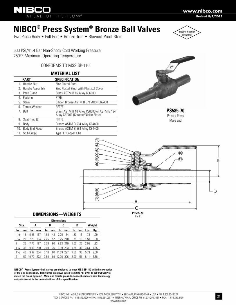
NIBCO® Press System® Bronze Ball Valves Two-PieceBody•FullPort•BronzeTrim•Blowout-ProofStem
600 PSI/41.4 Bar Non-Shock Cold Working Pressure250°F Maximum Operating Temperature
CONFORMS TO MSS SP-110
MATERIAL LIST PART SPECIFICATION 1. Handle Nut Zinc Plated Steel 2. Handle Assembly Zinc Plated Steel with Plastisol Cover 3. Pack Gland Brass ASTM B 16 Alloy C36000 4. Packing PTFE 5. Stem Silicon Bronze ASTM B 371 Alloy C69430 6. Thrust Washer RPTFE 7. Ball Brass ASTM B 16 Alloy C36000 or ASTM B 124 Alloy C37700 (Chrome/Nickle Plated) 8. Seat Ring (2) RPTFE 9. Body Bronze ASTM B 584 Alloy C84400 10. Body End Piece Bronze ASTM B 584 Alloy C84400 11. Stub Out (2) Type “L” Copper Tube
DIMENSIONS—WEIGHTS Dimensions Size A B C D Weight
In. mm. In. mm. In. mm. In. mm. In. mm. Lbs. Kg. ¹⁄₂ 15 6.56 167 1.88 48 7.25 184 .50 13 .73 .99 ³⁄₄ 20 7.25 184 2.25 57 8.25 210 .75 19 1.50 .68 1 25 7.75 197 2.38 60 8.63 219 1.00 25 2.05 .93 1 ¹⁄₄ 32 9.06 230 3.00 76 9.19 233 1.25 32 3.64 1.65 1 ¹⁄₂ 40 9.99 254 3.16 80 11.69 297 1.50 38 5.73 2.60 2 50 10.72 272 3.50 89 12.06 306 2.00 51 8.11 3.68
PS585-70P x P
NIBCO® Press System® ball valves are designed to meet MSS SP-110 with the exception of the end connection. Ball valves are down-rated from 600 PSI CWP to 200 PSI CWP to match the Press System®. Male and female press-to-connect ends are new technology not yet covered in the current edition of this specification.
PS585-70Press x Press
Male End
Revised 8/7/2012

NIBCO INC. WORLD HEADQUARTERS • 1516 MIDDLEBURY ST. • ELKHART, IN 46516-4740 • USA • PH: 1.800.234.0227 TECH SERVICES PH: 1.888.446.4226 • FAX: 1.888.234.0557 • INTERNATIONAL OFFICE PH: +1.574.295.3327 • FAX: +1.574.295.3455
www.nibco.com
32
A H E A D O F T H E F L O W®
www.nibco.com
NIBCO® Press System® Bronze Ball Valves
PS585-70-66P x P
DezincificationResistantTwo-PieceBody•FullPort•StainlessTrim•Blowout-ProofStem•VentedBall
600 PSI/41.4 Bar Non-Shock Cold Working Pressure250°F Maximum Operating TemperatureNominal sizes 1/2" through 1" are UL certified to NSF/ANSI 61
CONFORMS TO MSS SP-110
PS585-70-66Press x Press
Male End
MATERIAL LIST PART SPECIFICATION 1. Handle Nut Zinc Plated Steel 2. Handle Assembly Zinc Plated Steel with Plastisol Cover 3. Pack Gland Brass ASTM B 16 Alloy C36000 4. Packing PTFE 5. Stem ASTM A 276 Alloy S31600 Stainless Steel 6. Thrust Washer RPTFE 7. Ball ASTM A 276 Alloy S31600 Stainless Steel 8. Seat Ring (2) RPTFE 9. Body Bronze ASTM B 584 Alloy C84400 10. Body End Piece Bronze ASTM B 584 Alloy C84400 11. Stub Out (2) Type “L” Copper Tube
DIMENSIONS—WEIGHTS Dimensions Size A B C D Weight In. mm. In. mm. In. mm. In. mm. In. mm. Lbs. Kg. ¹⁄₂ 15 6.56 167 1.88 48 7.25 184 .50 13 .73 .33 ³⁄₄ 20 7.25 184 2.25 57 8.25 210 .75 19 1.50 .68 1 25 7.75 197 2.38 60 8.63 219 1.00 25 2.05 .93 1 ¹⁄₄ 32 9.06 230 3.00 76 9.19 233 1.25 32 3.86 1.75 1 ¹⁄₂ 40 9.99 254 3.16 80 11.69 297 1.50 38 5.79 2.63 2 50 10.72 272 3.50 89 12.06 306 2.00 51 8.84 4.00
NIBCO® Press System® ball valves are designed to meet MSS SP-110 with the exception of the end connection. Ball valves are down-rated from 600 PSI CWP to 200 PSI CWP to match the Press System®. Male and female press-to-connect ends are new technology not yet covered in the current edition of this specification.
Revised 8/7/2012

NIBCO INC. WORLD HEADQUARTERS • 1516 MIDDLEBURY ST. • ELKHART, IN 46516-4740 • USA • PH: 1.800.234.0227 TECH SERVICES PH: 1.888.446.4226 • FAX: 1.888.234.0557 • INTERNATIONAL OFFICE PH: +1.574.295.3327 • FAX: +1.574.295.3455
www.nibco.com33
A H E A D O F T H E F L O W®
www.nibco.com
NIBCO® Press System® Bronze Ball Valves Two-PieceBody•FullPort•BronzeTrim•³⁄₄" Hose Connection withCapandChain•Blowout-ProofStem
600 PSI/41.4 Bar Non-Shock Cold Working Pressure250°F Maximum Operating Temperature
CONFORMS TO MSS SP-110
PS585-70-HCPress Male x Hose End
MATERIAL LIST PART SPECIFICATION 1. Handle Nut Zinc Plated Steel 2. Handle Zinc Plated Steel 3. Pack Gland Brass ASTM B 16 Alloy C36000 4. Packing PTFE 5. Thrust Washer RPTFE 6. Stem Silicon Bronze ASTM B 371 Alloy C69430 7. Ball Brass ASTM B 16 Alloy C36000 or ASTM B 124 Alloy C37700 (Chrome/Nickle Plated) 8. Seat Rings Reinforced PTFE 9. Body Assembly Bronze ASTM B 584 Alloy C84400 10. Hose Body End Brass ASTM B 124 Alloy C37700 11. Cap Die Cast Brass 12. Gasket Rubber 13. Chain Brass 14. Stub Out Type “L” Copper Tube Cap is for hose end thread protection only. Not to be used for pressure containing purposes.
DIMENSIONS—WEIGHTS Dimensions Size A B C Weight
In. mm. In. mm. In. mm. In. mm. Lbs. Kg. ¹⁄₂ 15 4.90 124 1.88 48 7.19 183 .81 .37 ³⁄₄ 20 5.47 139 2.25 57 8.25 210 1.54 .70
PS585-70-HCPress x Hose
NIBCO® Press System® ball valves are designed to meet MSS SP-110 with the exception of the end connection. Ball valves are down-rated from 600 PSI CWP to 200 PSI CWP to match the Press System®. Male and female press-to-connect ends are new technology not yet covered in the current edition of this specification.
Revised 8/7/2012

NIBCO INC. WORLD HEADQUARTERS • 1516 MIDDLEBURY ST. • ELKHART, IN 46516-4740 • USA • PH: 1.800.234.0227 TECH SERVICES PH: 1.888.446.4226 • FAX: 1.888.234.0557 • INTERNATIONAL OFFICE PH: +1.574.295.3327 • FAX: +1.574.295.3455
www.nibco.com
34
A H E A D O F T H E F L O W®
www.nibco.com
MATERIAL LIST PART SPECIFICATION
1. Body Bronze ASTM B584 Alloy C84400 2. Cap Bronze ASTM B62 Alloy C83600 3. Gasket PTFE 4. Screen ASTM E2016 20 Mesh - 304 Stainless Steel or ASTM E674 Perforated - 304 Stainless Steel
5. Plug Brass ASTM B16 Alloy C36000 or Bronze ASTM B584 Alloy C84400 6. Female Adapter (2) Bronze ASTM B61 Alloy C92200 7. O-Ring (2) EPDM
Class 125 Bronze Y-StrainersScrew-inCap•TappedCapw/Blow-offPlugorSolidCap•20MeshSSScreenorSSPerforatedScreen
200 PSI/13.8 Bar Non-Shock Cold Working Pressure250° F Maximum Operating Temperature
PF221/222-APress x PressFemale End
DIMENSIONS—WEIGHTS—QUANTITIES Dimensions
Size A C D Weight
In. mm. In. mm. In. mm. Threads Lbs. Kg. ¹⁄₂ 15 2.96 75 1.79 45 1/4 NPT 0.66 0.30 ³⁄₄ 20 3.94 100 2.14 54 3/8 NPT 1.21 0.55 1 25 4.66 118 2.79 71 3/8 NPT 1.88 0.86 1¹⁄₄ 32 5.47 139 3.23 82 3/4 NPT 3.10 1.41 1¹⁄₂ 40 6.05 154 3.61 92 3/4 NPT 4.64 2.10 2 50 7.40 188 4.99 127 1 NPT 7.48 3.39
PF221/222-AP x P
CONFORMS TO MSS SP-110
PF221/222-BP x P
PF221/222-BPress x PressFemale End
END CONNECTION SCREEN CAP
PF- Female Press 221 - 20 Mesh (STD.) A - Tapped Cap w/Plug (STD.)
PF - Female Press 222 - Perforated B - Solid Cap
Revised 8/7/2012

NIBCO INC. WORLD HEADQUARTERS • 1516 MIDDLEBURY ST. • ELKHART, IN 46516-4740 • USA • PH: 1.800.234.0227 TECH SERVICES PH: 1.888.446.4226 • FAX: 1.888.234.0557 • INTERNATIONAL OFFICE PH: +1.574.295.3327 • FAX: +1.574.295.3455
www.nibco.com35
A H E A D O F T H E F L O W®
www.nibco.com
A wide variety of handles are available to fulfill safety and operation requirements in various processing and manufacturing industries. The lever handle with plastic cover is standard. Other handle options are shown. Stainless steel lever handles are available, as an option, also with plastic covers. If an optional handle is desired, please indicate which one when ordering. Many of these options are field assembly only.
CS Standard Lever Handle NIB-SEAL® HandleCS Extended Lever Handle
with Memory Stop
CS Locking Lever Handle Vertical Chain LeverCS Round Handle
SS Standard Lever Handle Horizontal Chain LeverCS Extended Round Handle
SS Locking Lever Handle Memory Stop KitCS Wing Handle
CS Extended Lever Handle
NIBCO® Press System® Ball Valve Handle Options
Revised 8/7/2012

NIBCO INC. WORLD HEADQUARTERS • 1516 MIDDLEBURY ST. • ELKHART, IN 46516-4740 • USA • PH: 1.800.234.0227 TECH SERVICES PH: 1.888.446.4226 • FAX: 1.888.234.0557 • INTERNATIONAL OFFICE PH: +1.574.295.3327 • FAX: +1.574.295.3455
www.nibco.com
36
A H E A D O F T H E F L O W®
www.nibco.com
NIBCO® Press System® Bronze Ball ValvesNIB-SEAL® Technical Data
NIBCO® bronze ball valves installed with NIB-SEAL® insulated handles are the only approach that keeps your insulated piping system completely intact.
The revolutionary NIB-SEAL® bronze ball valve stops condensate cold. Its unique thermal barrier design keeps mois-ture from infiltrating your insulated system while preventing thermal energy loss through exposed metal handles.
Designed for new installations or retrofitting existing systems, NIB-SEAL bronze ball valves offer a wide range of advantages for typical commercial HVAC systems as well as industrial applications where insulated piping is desirable.
• Protectivesleeveprovidesastationarysurfacetoaffixtheinsulation,allowingoperationandmaintenanceofthevalve without destroying the integrity of the insulated system.
• High-strengthcylindricalhandledesignfeatureseasyaccesstostandardadjustablememorystopforsystem balancing. The valve packing is also readily accessible for routine maintenance.• Capandinsulatingplugprovideavaporsealtopreventexchangeofairtomaximizetheefficiencyofyourinsulated
piping system.• Positionindicatorsallowat-a-glancedeterminationofwhethervalveisinopenorclosedposition.• Pre-formedholeallowsforconvenienttagging.
Temperature range: 15° F to 250° F
Cap keeps moisture-laden air out to reduce chance of condensate formation
Insulation plug provides vapor seal, keeping air from infiltrating the insulated system
Handle nut
Indicator gives at-a-glance valve position
Memory stop plate and screws for system balancing
Pre-formed hole for identification tag
Extension handle of durable non-thermal conductive material prevents formation of condensation
Protective sleeve allows operation of valve handle and maintenance of valve packing while maintaining integrity of piping insulation
NIBCO® Press System® bronze ball valve is an integral part of the NIB-SEAL® valve system
US PATENT 5,236,006
Revised 8/7/2012

NIBCO INC. WORLD HEADQUARTERS • 1516 MIDDLEBURY ST. • ELKHART, IN 46516-4740 • USA • PH: 1.800.234.0227 TECH SERVICES PH: 1.888.446.4226 • FAX: 1.888.234.0557 • INTERNATIONAL OFFICE PH: +1.574.295.3327 • FAX: +1.574.295.3455
www.nibco.com37
A H E A D O F T H E F L O W®
www.nibco.com
Butterfly Valve Options and AccessoriesLever-Lock Operator (Standard)PFD2000
Position-Lock Operator (Optional)PFD2000
1. Handle Polymer Coated Iron 2. Lever-Lock Zinc Plated Steel 3. Throttle Plate Zinc Plated Steel
MATERIAL LIST PART SPECIFICATION
DIMENSIONS AND TORQUE OUTPUT PFD Dimensions Torque Rated Output in Inch-Pounds Lever Throttle Plate Throttle Plate/ Size (STD) (STD) Infinite Pos. Kit A B C D At 60 pounds Pull At 100 pounds Pull
2¹⁄₂”-3” T115107PP T115138PP T114841FG 10¹⁄₂ 1 4⁵⁄₈ 6³⁄₁₆ 540 In-Lbs. 900 In-Lbs. 4 T115108PP T115138PP T114842FG 10¹⁄₂ 1 4⁵⁄₈ 6³⁄₁₆ 540 In-Lbs. 900 In-Lbs.
The lever-lock handle and throttling plate provide throttling notch-es every 10o for excellent manual control in balancing up to 90o or shut off service. The valve may be padlocked in any one of the positions including opened or closed by virtue of a locking hole located in the handle and lever.
The position-lock can be used to set the valve in any position or as a memory stop so the valve may be reopened to the previous position. The valve may be padlocked in full open or full closed position.
Ordering: Sold as a field retrofitable kit only.
Cast Iron Gear OperatorThe NIBCO® butterfly valve can be provided with heavy-duty operator and indicator. Recommended for valves 8" and larger, for trouble-free operation in all moisture and weather conditions (not submersible). Operator is a self-locking worm gear type. Equipped with adjustable stops at open and shut positions. Ordering: Specify by adding (-5) to Fig. No., i.e., PFD2000-5. Babbit Sprocket may be added to handwheel. See below for sizing information. Available options: Memory Stop Gear Operator Kit, 2" Square Operating Nut, Flag Indicator and Handwheel for GO.
Gear Operator options and accessories (2 1/2" through 4" 2000 series only)2" Square Operating Nut Memory Stop Flag Indicator
2 1/2"-4"Consult factory for: Square Operating Nut, Memory Stop and Flag Indicator
Notes - 1. Stem adapter bushing must be ordered seperately when needed for smaller size valves. 2. All other accessories must be ordered separately. (Sprocket rim, square operator nut, flag indicator & memory stop kit.) 3. Gear operator comes with handwheel.
GEAR OPERATOR DETAIL FOR SIZES 2 1/2" TO 4" (PFD2000 ONLY) GEAR OPERATOR ACCESSORIES & REPLACEMENT PARTS GEAR GEAR DIMENSIONS (INCHES) STEM SPROCKET SQUARE FLAG MEMORY REPLACEMENT OPERATOR RATIO OP ADAPTER RIM OPERATING
INDICATOR
STOP KIT
HANDWHEEL NUMBER WEIGHT A B C D E F BUSHING MODEL NUT T117118PP 24:1 10 7.64 1.77 5.04 4.24 5.91 2.79 T046653PP #11/2 T117792FC T116682PP T026196PP T117122PPT117118PP 24:1 10 7.64 1.77 5.04 4.24 5.91 2.79 T046654PP #11/2 T117792FC T116682PP T026196PP T117122PP
PFDVALVE
21/2 - 34
Revised 8/7/2012

NIBCO INC. WORLD HEADQUARTERS • 1516 MIDDLEBURY ST. • ELKHART, IN 46516-4740 • USA • PH: 1.800.234.0227 TECH SERVICES PH: 1.888.446.4226 • FAX: 1.888.234.0557 • INTERNATIONAL OFFICE PH: +1.574.295.3327 • FAX: +1.574.295.3455
www.nibco.com
38
A H E A D O F T H E F L O W®
www.nibco.com
Butterfly Valve Technical InformationValve Installation ProcedureAlways position the connecting pipe flanges accurately in the line, allowing sufficient space between the flanges for the valve. Make sure the pipe flangefaces are clean of any foreign material such as scale, metal shavings or welding slag. Valves should be installed with the disc in the closed position to prevent damage to sealing surfaces. 1. Carefully insert the valves between the pipe flanges. Do not apply any lubricants to the seat faces as this may damage them. 2. Line up, center and secure the valve between flanges using desired bolts or studs as listed in Table 4. Do not tighten bolts at this time. 3. Carefully open the valve to assure free unobstructed disc movement. Disc interference may result when valves are installed in pipelines having smaller than normal inside diameters, such as heavy wall pipe, plastic-lined pipe, as-cast flanges or reducing flanges. Interference can also occur when connecting directly to a swing check or silent check. Suitable corrective measures must be taken to remove these obstructions, such as taper boring the pipe or installing a spacer or spool piece. 4. After proper operation is verified, tighten the bolts using a cross-over pattern (Fig. 1) to the minimum recommended bolt torques listed in Table 3. 5. Pressurize piping to valve and inspect for leakage. If leakage is observed, tighten bolts using cross-over pattern, increasing torque until leak stops. DO NOT EXCEED MAXIMUM TORQUES LISTED IN TABLE 3. 6. Recommended torques are made without warranty. Installer must verify proper strength bolts for application. Bolts shall be clean and un-lubricated.
4
2
1
3
8
6
5
7
Bolt TighteningCross Over Pattern
Fig. 1
SuggestedBolting Method
Flange Bolt Minimum Bolt Maximum Bolt Size Size Torque(ft.•lbs.) Torque(ft.•lbs.) 2 1/2"- 4" 5/8" 20 70
Table 3 Recommended Bolt Tightening Torques
Caution1. Class 250 cast iron and Class 300 steel flanges can not be used on these valves.2. Rubber faced or mechanical flanges are not recommended.3. This valve is not recommended for steam service.4. Valves should not be assembled to the flanges and then welded into the piping system.5. Do not install EPDM liner in compressed air lines.
2 1/2" 1.81
0.69 — — — — 1.50 8/4 5/8-11 UNC — 0.88 — — — 1.75 8/4
3" 1.81
0.75 — — — — 1.50 8/4 5/8-11 UNC — 0.94 — — — 1.75 8/4
4" 2.06 0.94 0.94 — — — 1.75 16/8 5/8-11 UNC
VA
LVE
SIZ
E10
00/2
000/
3000
SE
RIE
S O
NLY
TO
TAL
VA
LVE
BO
DY
WID
TH
AN
SI B
16.1
CLA
SS
125
CA
ST
IRO
NFL
AN
GE
TH
ICK
NE
SS
AN
SI B
16.5
CLA
SS
150
ST
EE
LFL
AN
GE
TH
ICK
NE
SS
AN
SI B
16.4
7 (S
ER
IES
A)
CLA
SS
150
ST
EE
LM
SS
SP
-44
FLA
NG
E T
HIC
KN
ES
S
AN
SI B
16.4
7 (S
ER
IES
B)
CLA
SS
150
ST
EE
LW
ELD
NE
CK
FLA
NG
E T
HIC
KN
ES
S
AN
SI B
16.4
7 (S
ER
IES
B)
CLA
SS
150
ST
EE
LB
LIN
D S
TY
LEFL
AN
GE
TH
ICK
NE
SS
RE
CO
MM
EN
DE
DC
AP
SC
RE
W L
EN
GT
H(L
UG
GE
D V
ALV
ES
)(C
)
TO
TAL
QU
AN
TIT
YC
AP
SC
RE
WS
/BO
LTS
(TO
MO
UN
T 2
FLA
NG
ES
)
CA
P S
CR
EW
SIZ
ETable 4 Recommended Bolt Lengths
Resilient Liner Materials
EPDM – EPDM is a terpolymer elastomer made from ethylene-propylene diene monomer. EPDM has good abrasion and tear resistance and offers excellent chemical resistance to a variety of acids and alkalines. It is susceptible to attack by oils and is not recommended for applications involving petroleum oils, strong acids or strong alkalines. EPDM should not be used on compressed air lines. It has exceptionally good weather aging and ozone resistance. It is fairly good in ketones and alcohols.
Proprietary compound formulas are used for each of the elastomers to provide the right combination of seat compression, abrasion resistance and chemical resistance to match your application. Elastomeric seat materials are not suitable for steam service.
Revised 8/7/2012

NIBCO INC. WORLD HEADQUARTERS • 1516 MIDDLEBURY ST. • ELKHART, IN 46516-4740 • USA • PH: 1.800.234.0227 TECH SERVICES PH: 1.888.446.4226 • FAX: 1.888.234.0557 • INTERNATIONAL OFFICE PH: +1.574.295.3327 • FAX: +1.574.295.3455
www.nibco.com39
A H E A D O F T H E F L O W®
www.nibco.com

NIBCO INC. WORLD HEADQUARTERS • 1516 MIDDLEBURY ST. • ELKHART, IN 46516-4740 • USA • PH: 1.800.234.0227 TECH SERVICES PH: 1.888.446.4226 • FAX: 1.888.234.0557 • INTERNATIONAL OFFICE PH: +1.574.295.3327 • FAX: +1.574.295.3455
www.nibco.com
40
A H E A D O F T H E F L O W®
www.nibco.com
NIBCO® Press System® ToolsPC-2801/2" through 4"
MATERIAL LISTMODEL NO. DESCRIPTION LBS.
PC-280 Pressing Tool with 2 - 18V, 3.0 Ah Lithium-ion batteries, 110V battery charger & case 25.40 PC-10S 1/2" Standard Pressing Jaw (for PC-100 or PC-280) 4.14PC-11S 3/4" Standard Pressing Jaw (for PC-100 or PC-280) 4.18PC-12S 1" Standard Pressing Jaw (for PC-100 or PC-280) 4.52PC-13S 1 1/4" Standard Pressing Jaw (for PC-100 or PC-280) 4.30PC-14S 1 1/2" Standard Pressing Jaw (for PC-100 or PC-280) 9.61PC-15S 2" Standard Pressing Jaw (for PC-100 or PC-280) 9.26 PC-16S 1/2"-1 1/4" (4 jaws) Standard Press Jaw Kit w/Case (for PC-100 or PC-280) 25.25PC-17S 1 1/2"-2" (2 jaws) Standard Press Jaw Kit w/Case (for PC-100 or PC-280) 23.76 PC-2 2 1/2" Pressing Chain w/Case (for PC-100 or PC-280) 18.58PC-3 3" Pressing Chain w/Case (for PC-100 or PC-280) 19.40PC-4 4" Pressing Chain w/Case (for PC-100 or PC-280) 23.81PC-234 2 1/2", 3" & 4" Pressing Chain Kit (for PC-100 or PC-280) 44.42 PC-5 PC-5 Pressing Chain Adapter Jaw (note: must be used with 2 1/2", 3" & 4" chains) 7.01 PC-7L 18V, 3.0Ah Lithium-ion Battery (for PC-280 or PC-20M) 1.30PC-8L 110V Battery Charger (for PC-4ML or PC-7L) 2.20PC-9L AC Adapter (for PC-280 or PC-20M) 1.70
PC-280C Plastic Replacement Case for PC-280 Tool 7.50PC-2C Metal Replacement Case for PC-2 or PC-3 Chain 8.10PC-4C Metal Replacement Case for PC-4 Chain 8.10PC-234C Plastic Replacement Case for PC-234 Chain Kit 7.72PC-16SC Metal Replacement Case for PC-16S (1/2" - 1 1/4" Jaws) 8.10PC-17SC Metal Replacement Case for PC-17S (1 1/2" - 2" Jaws) 4.40
PC-51 1/2" - 2" Deburring Tool 0.92
PC-10S thru PC-15SStandard Pressing Jaw
PC-2 thru PC-4Pressing Chain
PC-5Pressing Chain Adapter
Jaw
PC-7L18V, 3.0 Ah
Lithium-ion Battery
PC-8L110V Battery Charger
PC-9LAC Adapter
PC-280Pressing Tool
PC-511/2" - 2" Deburring Tool
Revised 12/19/2012

NIBCO INC. WORLD HEADQUARTERS • 1516 MIDDLEBURY ST. • ELKHART, IN 46516-4740 • USA • PH: 1.800.234.0227 TECH SERVICES PH: 1.888.446.4226 • FAX: 1.888.234.0557 • INTERNATIONAL OFFICE PH: +1.574.295.3327 • FAX: +1.574.295.3455
www.nibco.com41
A H E A D O F T H E F L O W®
www.nibco.com
NIBCO® Press System® ToolsPC-20M1/2" through 1"
MATERIAL LISTMODEL NO. DESCRIPTION LBS.
PC-20M Mini Pressing Tool, 2 - 18V, 1.3 Ah Lithium-ion batteries, 110V charger & case (NO jaws) 11.00PC-200M Mini Pressing Tool, 3 Jaws, 2 - 18V, 1.3 Ah Lithium-ion batteries, 110V charger & case 18.00 PC-1M 1/2" Jaw (for Mini Pressing Tool - PC-10M or PC-20M) 2.09PC-2M 3/4" Jaw (for Mini Pressing Tool - PC-10M or PC-20M) 2.05PC-3M 1" Jaw (for Mini Pressing Tool - PC-10M or PC-20M) 2.07 PC-4ML 18V, 1.3Ah Lithium-ion Battery (for PC-20M) 0.80PC-7L 18V, 3.0Ah Lithium-ion Battery (for PC-280 or PC-20M) 1.30PC-8L 110V Battery Charger (for PC-4ML and PC-7L) 2.20PC-9L AC Adapter (for PC-280 or PC-20M) 1.70
PC-20MC Plastic Replacement Case for PC-10M & PC-20M) 4.00PC-50 1/2" - 1" Deburring Tool 0.42
PC-7L18V, 3.0 Ah
Lithium-ion Battery
PC-1M, 2M, 3MMini Pressing Jaw
PC-20MMini Pressing Tool
PC-200MMini Pressing Tool with 1/2", 3/4" and 1" Jaws
PC-501/2" - 1" Deburring Tool
PC-4ML18V, 1.3 Ah
Lithium-ion Battery
PC-8L110V Battery Charger
PC-9LAC Adapter
Revised 8/7/2012

NIBCO INC. WORLD HEADQUARTERS • 1516 MIDDLEBURY ST. • ELKHART, IN 46516-4740 • USA • PH: 1.800.234.0227 TECH SERVICES PH: 1.888.446.4226 • FAX: 1.888.234.0557 • INTERNATIONAL OFFICE PH: +1.574.295.3327 • FAX: +1.574.295.3455
www.nibco.com
42
A H E A D O F T H E F L O W®
www.nibco.com
PC-280 & PC-20M FEATURES
TOOLS
Light weight PC-20MMini:3.7lbs.(withoutjaw) PC-280:9.4lbs.(withoutjaw)
Easy to handle / simple design Jaws rotate 350° No calibration necessary No complicated switches or controls Mini: Ergonomic compact design is easy to use in tight spaces
Interruptible crimp cycle Safetyfeaturepreventsinjuries
Can begin crimp, stop to align and level fitting / tube, and complete crimp
Battery Can be changed during crimp cycle Lithium-ion has short charging cycle and larger capacity •PC-4ML:15minuterechargetime •PC-7L:22minuterechargetime
AC Power Adapter Converts the tool to electric power Allows continuous use
Service light Illuminates at 10,000 cycles
Tool will not stop operating when light illuminates •REDindicatesbatterychargestatus,service intervals, tool functions & faults •WHITEilluminatestheworkarea
Hydraulic Pressure Check (HPC) An audible warning signal sounds if adequate work-
ing pressure is not achieved
PRESSING CHAINS (2 1/2" to 4" ONLY)
Uniform crimp Maintains proper pipe alignment
Easy to install and remove Once secured to fitting, chain cannot fall off prior to crimp Chain easily removed post crimp
Crimp Identification Easy to identify crimp has been made from a distance
MATERIAL LISTMODEL NO. DESCRIPTION LBS.
PC-6 12V, NiMH Battery - 2.6Ah for PC-100 1.51PC-7 12V, NiMH Battery - 3.0Ah for PC-100 1.57PC-8 120V Standard Battery Charger for PC-6 or PC-7 1.10PC-9 AC Adapter for PC-100 Press Tool 1.32 PC-4M 1.3 Ah NiCd 9.6V Battery for Mini Pressing Tool 0.85PC-5M 120V Charger for Mini Pressing Tool 1.13 PC-100C Metal Case for PC-100 Tool 14.30
NIBCO® Press System® ToolsPC-100 and PC-10M Accessories
PC-712V, 3.0 Ah
NiMH Battery
PC-4M9.6V, 1.3 Ah
NiMH Battery
PC-8120V Battery Charger
PC-9AC Adapter
Revised 8/7/2012

NIBCO INC. WORLD HEADQUARTERS • 1516 MIDDLEBURY ST. • ELKHART, IN 46516-4740 • USA • PH: 1.800.234.0227 TECH SERVICES PH: 1.888.446.4226 • FAX: 1.888.234.0557 • INTERNATIONAL OFFICE PH: +1.574.295.3327 • FAX: +1.574.295.3455
www.nibco.com43
A H E A D O F T H E F L O W®
www.nibco.com
NIBCO® Press System® Approved Tool and Jaw Compatibility MatrixPressing tool, jaw and chain sets are an integral part of ensuring a reliable, permanent connection between NIBCO® Press System® fittings, valves and copper piping. Only use pressing tools, jaws and chain sets that have been tested and approved for use with NIBCO Press System fittings and valves.
For the latest listing of approved Pressing tool, jaw and chain combinations, visit nibco.com.NIBCO recommends minor tool service performed once per year and major service every three years. For technical or service assistance, contact NIBCO Technical Services 1-888-446-4226.
RIDGID® is a registered trademark of RIDGID Inc.ProPress® is a registered trademark of Viega NA.ROMAX® is a registered trademark of ROTHENBERGER USA LLCVIRAX® is a registered trademark of The Stanley Works.
CAUTION:NIBCO Press Fittings and Valves (2½”, 3”, 4” ends) to be installed ONLY with NIBCO Pressing Tools & Chains.
1/2”
- 1”
NIB
CO P
ress
Syst
em M
ini
Pres
sing
Jaw
s (P
C-1M
, PC-
2M, P
C-3M
)
1/2”
- 1”
RID
GID®
Pro
Pres
s® C
ompa
ct
Pres
sing
Jaw
s
1/2”
- 1-
1/4”
RID
GID®
Pro
Pres
s® C
1 Co
mpa
ct K
it (C
1 Ac
tuat
or &
Pre
ss R
ings
)
Roth
enbe
rger
Com
pact
Pre
ssin
g Ja
ws
Stan
ley®
VIR
AX®
Pre
ss In
serts
1/2”
- 2”
NIB
CO P
ress
Syst
em S
tand
ard
Pres
sing
Jaw
s (P
C-10
S, P
C-11
S, P
C-12
S, P
C-13
S,PC
-14S
, PC-
15S)
1/2”
- 2”
RID
GID®
Pro
Pres
s® S
tand
ard
Pres
sing
Jaw
s
1/2”
- 1-
1/4”
RID
GID®
Pro
Pres
s® V
1 Ki
t (V
1 Ac
tuat
or &
Pre
ss R
ings
)
1/2”
- 2”
Rot
henb
erge
r Sta
ndar
d
Pr
essi
ng J
aws
1/2”
2”
REM
S St
anda
rd P
ress
ing
Jaw
s
Stan
ley®
VIR
AX®
Pre
ssin
g Ja
ws
2 1/
2” -
4” N
IBCO
Pre
ssin
g Ch
ains
(PC-
2, P
C-3,
PC-
4)
PRES
SIN
G T
OO
LS
SIZE 1/2” - 1” 1/2” - 2” 21/2” - 4”
NIBCO PC-280 — — — — — YES YES YES YES YES YES YES
NIBCO PC-100 — — — — — YES YES YES YES YES YES YES
RIDGID® 320-E — — — — — YES YES YES — — — —
RIDGID® RP 330-B — — — — — YES YES YES — — — —
RIDGID® CT400 — — — — — YES YES YES — — — —
RIDGID® RP 330-C — — — — — YES YES YES — — — —
Rothenberger ROMAX® Pressliner
— — — — — — — — YES — — —
Rothenberger ROMAX® AC ECO
— — — — — — — — YES — — —
REMS Akku-Press — — — — — — — — — YES — —
REMS Power-Press — — — — — — — — — YES — —
Stanley® VIRAX® P20+ — — — — — — — — — — YES —
NIBCO PC-20M Mini YES — — YES — — — — — — — —
NIBCO PC-10M Mini YES — — YES — — — — — — — —
RIDGID® 100-B Compact — YES YES — — — — — — — — —
RIDGID® RP 210-B Compact — YES YES — — — — — — — — —
Rothenberger Compact YES — — YES — — — — — — — —
Stanley® VIRAX® M20+ Compact
— — — — YES — — — — — — —
The following table details compatibility of approved pressing tools, chains and jaws with the NIBCO Press System fittings and valves:
Revised 8/7/2012

NIBCO INC. WORLD HEADQUARTERS • 1516 MIDDLEBURY ST. • ELKHART, IN 46516-4740 • USA • PH: 1.800.234.0227 TECH SERVICES PH: 1.888.446.4226 • FAX: 1.888.234.0557 • INTERNATIONAL OFFICE PH: +1.574.295.3327 • FAX: +1.574.295.3455
www.nibco.com
44
A H E A D O F T H E F L O W®
www.nibco.com
Engineering Data

NIBCO INC. WORLD HEADQUARTERS • 1516 MIDDLEBURY ST. • ELKHART, IN 46516-4740 • USA • PH: 1.800.234.0227 TECH SERVICES PH: 1.888.446.4226 • FAX: 1.888.234.0557 • INTERNATIONAL OFFICE PH: +1.574.295.3327 • FAX: +1.574.295.3455
www.nibco.com45
A H E A D O F T H E F L O W®
www.nibco.com
NIBCO® Press System® — Engineering Data Copper and Copper Alloy FittingsStandardsO-Ring seal joints are not new to the piping industry, but joining techniques like the NIBCO® Press System® are providing new alternatives for copper piping assembly. Although there are no nationally recognized standards for these fit-tings, NIBCO has relied on its century of experience in copper and brass piping products to design the best performing and most dependable line of fittings possible.
ApplicationsThe NIBCO® Press System® fittings are designed to join with ASTM B 88 seam-less copper water tube in residential and commercial potable, hot, chilled and process water applications for plumbing and HVAC systems. Copper and copper alloy materials and EPDM elastomeric seals have a long history of compatibility with common chemicals used in these systems. A chemical resistance chart should always be referenced when other fluids are to be introduced.
NOTE: FLUIDS CONTAINING HYDROCARBONS ARE NOT COMPATIBLE WITH THE EPDM SEAL.
Pressure/Temperature Limitations-20°F to 250°F up to 200 PSIG, non-shock working pressure.
Materials:• WrotCopper
◆ ASTM B 75 Alloy C12200
• CastCopper&BrassRodAlloy
◆ BS EN 1982:1999 Modified Alloy CC491K ◆ European Red Brass comparable to ASTM B 62
• ElastomericSeals ◆ EPDM O-Rings compliant with BS EN 681-1
PerformanceIn the absence of a nationally recognized standard, the following performance tests were developed and conducted. The fitting dimensions, materials of con-struction and performance tests were witnessed and verified by internationally recognized Underwriters Laboratories, Inc. A letter of verification is available upon request:
1. Dimensional Verification a. Inside diameter of press cup and waterway b. Outside diameter of press cup and waterway c. Wall thickness d. Threaded ends conformance to ASME B1.20.1 2. Hydrostatic Minimum Burst Strength Pressure a. Fitting samples hydrostatically tested to a minimum of 600 PSI (three times the rated internal working pressure) at 73°F. 3. Unrestrained Hydrostatic Pressure Test at 68°F (20°C) and 200°F (93°C) a. Fitting assemblies were filled with water and pressurized to 600 PSIG at 68° or 200°F for 48 hours. 4. Static Torque a. Fittings were filled with water, had a minimum torque applied and released. Each fitting was then pressurized to 400 PSIG for 48 hours. 5. Bending Test a. A sample fitting was installed between two equal lengths of hard- drawn copper tubing supported six (6) feet apart. A concentrated load was applied to the center of the fitting. The assembly was subjected to 400 PSIG water pressure for one (1) hour. 6. Vacuum Pressure Test a. Fittings were subjected to a vacuum pressure of 24.5 inches of mercury for one (1) hour. 7. Cyclic Pressure Test a. Fittings were subjected to a hydraulic shock pressure of 400 PSIG for 10,000 cycles. 8. Vibration Test a. Fitting assemblies were subjected to a hydrostatic cyclic vibration test at 350 PSIG for 1,000,000 cycles. After cycling, the assem- blies were pressurized to 400 PSIG for 30 minutes. 9. Thermocycling Test a. Fitting and tube assemblies were filled with air and pressur- ized to 100 PSIG. The water temperature was cycled from 68°F to 200°F for 2,500 cycles. Each temperature was held for 2 minutes and changed within two (2) minutes. 10. Dynamic Torque at 68°F (20°C) and 200°F (93°C) a. Fittings were assembled between two lengths of hard-drawn copper tubing. With one tube fixed, the other tube twisted ±5° for 10,000 cycles at 68°F (20°C) or 200°F (93°C). Each assembly was then subjected to 400 PSIG water pressure at 68°F (20°C) or 200°F (93°C) for 48 hours.Tests were performed with K, L and M hard drawn-copper tubing. A minimum of one fitting of each configuration of each size was tested.
Flow area consistent with ASME B16.22
NIBCO® Press Fittings meet all performance
requirements of ASME B16.22 and
B16.18
NOTE: Freezing Weather Precaution — Subsequent to testing a piping system, valve should be in an open position to allow complete drainage.
Revised 8/7/2012
NIBCO INC. WORLD HEADQUARTERS • 1516 MIDDLEBURY ST. • ELKHART, IN 46516-4740 • USA • PH: 1.800.234.0227 TECH SERVICES PH: 1.888.446.4226 • FAX: 1.888.234.0557 • INTERNATIONAL OFFICE PH: +1.574.295.3327 • FAX: +1.574.295.3455
www.nibco.com
46
A H E A D O F T H E F L O W®
www.nibco.com
FITTINGS2" and Smaller:Fittings shall comply with NSF 61, CSA, UPC and be approved by the local jurisdiction. The NIBCO® Press System® may be used at the contractor’s option for the
following building services piping - 20°F to +250°F up to 200 PSI:
• HotandColdDomesticWater • PotableWater • CondenserandChilledWaterService • HotWater Heating Service
Wrot copper press fittings shall be made from commercially pure copper mill products per ASTM B 75 Alloy C12200. Cast copper alloy press fittings shall be made from materials with a minimum of 78% copper and a maximum of 15% zinc. The press fittings connections shall be compatible with seamless K, L or M copper tube made to ASTM B 88. Fittings shall have a maximum non-shock working pressure of 200 PSI between the temperatures of -20°F and +250°F. Elastomeric seals shall be made of EPDM material, and the fittings shall be manufactured with an inboard bead design. All fittings shall be installed in accordance with the manufacturer’s installation instructions and according to local plumbing and mechanical codes. The press-to-connect joint shall be made with pressing tools and jaw sets recommended and authorized by NIBCO.
21/2" through 4":Fittings shall comply with NSF 61, CSA, UPC and be approved by the local jurisdiction. The NIBCO® Press System® may be used at the contractor’s option for the
following building services piping - 20°F to +250°F up to 200 PSI:
• HotandColdDomesticWater • PotableWater • CondenserandChilledWaterService • HotWater Heating Service
Wrot copper press fittings shall be made from commercially pure copper mill products per ASTM B 75 Alloy C12200. Cast copper alloy press fittings shall be made from materials with a minimum of 78% copper and a maximum of 15% zinc. The press fittings connections shall be compatible with seamless K, L or M copper tube made to ASTM B 88. Fittings shall have a maximum non-shock working pressure of 200 PSI between the temperatures of -20°F and +250°F. Elastomeric seals shall be made of EPDM material, and the fittings shall be manufactured with an inboard bead design. All fittings shall be installed in accordance with the manufacturer’s installation instructions and according to local plumbing and mechanical codes. The press-to-connect joint shall be made with pressing tools and jaw sets recommended and authorized by NIBCO.
NIBCO® Press System® — Sample Specification
Revised 8/7/2012

NIBCO INC. WORLD HEADQUARTERS • 1516 MIDDLEBURY ST. • ELKHART, IN 46516-4740 • USA • PH: 1.800.234.0227 TECH SERVICES PH: 1.888.446.4226 • FAX: 1.888.234.0557 • INTERNATIONAL OFFICE PH: +1.574.295.3327 • FAX: +1.574.295.3455
www.nibco.com47
A H E A D O F T H E F L O W®
www.nibco.com
NIBCO® Press System® — Sample Specification VALVES
2" and Smaller Ball Valves: (On/Off, Isolation or Throttling) Ball valves with male or female press-to-connect ends shall be rated at
200 PSI CWP to +250°F maximum. Valves shall be manufactured in ac-cordance with MSS SP-110 and constructed of dezincification resis-tant cast bronze bodies. No brass containing more than 15% zinc shall be approved. Valve shall have reinforced PTFE seats, blow-out proof stem, full-port ball, chrome/nickel plated ball or 316 SS ball for ag-gressive water conditions. Where piping is to be insulated, ball valves shall be equipped with 2” extended handles of non-thermal conductive material. Handle to have extended sleeve incorporating an insulation plug to provide a vapor barrier and allow valve operation without disturbing the insulation, and a memory stop, which can be set after installation.
Acceptable Valves: (non-insulated lines): NIBCO® PC585-70, PF585-70 or PS585-70
(Chrome/nickel plated ball) NIBCO® PC585-70-66, PF585-70-66, PS585-70-66 or PCM585-60
(316 SS ball) Acceptable Valves: (insulated lines): NIBCO® PC585-70-NS, PF585-70-NS or PS585-70-NS
(Chrome/nickel plated ball) NIBCO® PC585-70-66-NS, PF585-70-66-NS or PCM585-60-NS
(316 SS ball) (Note to Specifier: Include press gate valves in addition/in lieu of press ball valves for
ON/OFF and isolation services if requested or required.)
2" and Smaller Gate Valves: (On/Off and Isolation) Gate valves with male or female press-to-connect ends shall be rated to
200 PSI CWP at +250°F maximum. Valves shall be manufactured in accor-dance with MSS SP-80. Valve body, bonnet and wedge to be manufactured of dezincification resistant cast bronze (ASTM B 62). Stems shall be of silicon bronze (ASTM B 371) or low zinc alloy (ASTM B 99). Non-asbestos packing and malleable or ductile iron hand-wheel shall be standard.
Acceptable Valves: NIBCO® PF111 or PS111 - Rising Stem Gate Valve NIBCO® PF113 or PS113 - Non-Rising Stem Gate Valve
2" and Smaller Globe and Angle Valves: (Throttling Service) Globe and angle valves with male or female press-to-connect ends shall be
rated to 200 PSI CWP at +250°F maximum. Valves shall be manufactured in accordance with MSS SP-80. Valve body, bonnet and wedge to be manufac-tured of dezincification resistant cast bronze (ASTM B 62). Stems shall be of silicon bronze (ASTM B 371) or low zinc alloy (ASTM B 99). Non-asbestos packing and malleable or ductile iron hand-wheel shall be standard.
Acceptable Valves: NIBCO® PF211-Y or PS211-Y - Globe Valve NIBCO® PF311-Y or PS311-Y - Angle Valve
2" and Smaller Check Valves: (Back Flow Prevention) Check valves (Y pattern, swing type or in-line) with male or female press-
to-connect ends shall be rated at 200 PSI CWP to +250°F maximum. Valves shall be manufactured in accordance with MSS SP-80. Body and cap to be manufactured of dezincification resistant cast bronze (ASTM B 62 or ASTM B 584 Alloy C84400). Valves to have PTFE seat disc.
Acceptable Valves: NIBCO® PF413-Y or PS413-Y - Y Pattern, Swing Type Check Valve NIBCO® PF480-Y or PS480-Y - In-line spring loaded Silent Check Valve
Drain Valves At all low points in water piping to be drained or vented, provide 1/2” or 3/4"
ball valves with male or female press-to-connect ends by hose-end drain valves. Valves shall be rated by 200 PSI CWP to +250°F maximum. Valves shall be manufactured in accordance with MSS SP-110. Valves to be con-structed of dezincification resistant cast bronze bodies. Valve shall have rein-forced PTFE seats, blow-out proof stem, and be full port. All valves shall be provided with 3/4” hose connection with cap and chain.
Acceptable Valves: NIBCO® PS585-70-HC or PF585-70-HC
2 1/2" thru 4" Butterfly Valves: (On/Off, Isolation or Throttling) Butterfly valves with female press-to-connect ends shall be rated at 200 PSI
CWP to +250°F maximum. Valves shall be manufactured in accordance with MSS SP-67 and constructed of a ductile-iron body, for bubble-tight shutoff, extended-neck for insulation, disc and lining suitable for potable water, valves shall be suitable for bi-directional dead end service at full rated pres-sure, one-piece Type 416 stainless-steel stem, copper bushing, fasteners and pins shall not be used to attach stem to disc, no pins or fasteners in water-way, aluminum-bronze disc, and molded-in EPDM seat (liner).
Acceptable Valves: NIBCO® PFD2000 Series
Revised 8/7/2012

NIBCO INC. WORLD HEADQUARTERS • 1516 MIDDLEBURY ST. • ELKHART, IN 46516-4740 • USA • PH: 1.800.234.0227 TECH SERVICES PH: 1.888.446.4226 • FAX: 1.888.234.0557 • INTERNATIONAL OFFICE PH: +1.574.295.3327 • FAX: +1.574.295.3455
www.nibco.com
48
A H E A D O F T H E F L O W®
www.nibco.com
Installation Instructions

NIBCO INC. WORLD HEADQUARTERS • 1516 MIDDLEBURY ST. • ELKHART, IN 46516-4740 • USA • PH: 1.800.234.0227 TECH SERVICES PH: 1.888.446.4226 • FAX: 1.888.234.0557 • INTERNATIONAL OFFICE PH: +1.574.295.3327 • FAX: +1.574.295.3455
www.nibco.com49
A H E A D O F T H E F L O W®
www.nibco.com
NIBCO® Press System®
The NIBCO® Press System®, when used with tested and authorized pressing tools and jaws, is designed to mechanically crimp fittings and valves onto copper tubing to create a watertight, permanent seal. When the switch on the pressing tool is depressed, an internal motor powers a hydraulic pump which forces fluid into the cylinder of the tool, forcing the ram forward and applying thousands of pounds of crimping force onto the specially designed fittings and valves.
System ComponentsFittings and ValvesNIBCO® Press System® copper or bronze fittings and valves
TubingASTM B 88 seamless Hard Drawn Copper Water Tube: Types K, L and M.
Pressing Tools, Chains and JawsThe pressing tool, chain and jaw are important parts of ensuring a reliable, permanent connection between NIBCO® Press System® fittings and valves and the copper water tube.
CAUTION — Use only pressing tools and jaw sets that have been tested and authorized for use with NIBCO® Press System® fittings and valves (1). Use of unauthorized pressing tools and/or jaws may result in an improper seal that could cause extensive property damage.
Pressing Tool Safety• onlyuseauthorizedpressingtoolsandjawswithNIBCo® Press System®
fittings and valves. Other uses or modification of the jaws for other applica-tions may damage the press tool, damage the jaws and/or cause personal injury.
• Keepfingersandhandsawayfromjawsduringpressingcycle.Yourfingersor hands can be crushed, fractured or amputated if they become caught between the jaw tips or between the jaw and any other object.
• Alwayswearsafetyglasseswhileusingpressingtoolsandjaws.
• Never attempt to repair a damaged jaw set. A jaw that has been welded, ground, drilled or modified in any manner can shatter during crimping resulting in serious injury. Discard the entire damaged jaw set. Replace with a new jaw set.
NOTE: Consult manufacturer's pressing tool and jaw set operators manual to determine replaceable jaw set components.
WARNING: Please read these installation instructions and the manufac-turer's pressing tool and jaw operators manual(s) carefully prior to installa-tion of the NIBCO® Press System®. Failure to understand and follow the contents of this manual may result in extensive property damage, severe personal injury or death.
Please contact NIBCO Technical Services at 888.446.4226 if you have instal-lation questions.
NIBCO® Press System® — Installation Instructions
(1) See approved tool and jaw compatibility matrix on page 52.
Revised 8/7/2012
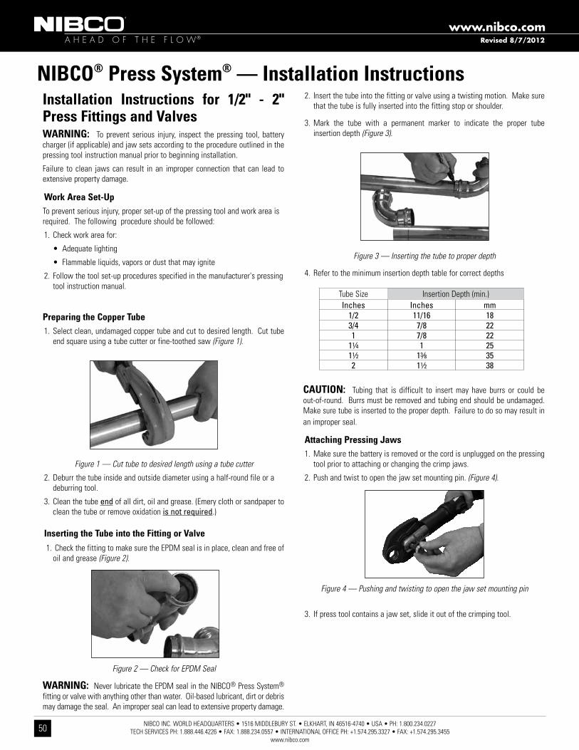
NIBCO INC. WORLD HEADQUARTERS • 1516 MIDDLEBURY ST. • ELKHART, IN 46516-4740 • USA • PH: 1.800.234.0227 TECH SERVICES PH: 1.888.446.4226 • FAX: 1.888.234.0557 • INTERNATIONAL OFFICE PH: +1.574.295.3327 • FAX: +1.574.295.3455
www.nibco.com
50
A H E A D O F T H E F L O W®
www.nibco.com
1/2"
- 1" N
IBCO
Press
Syste
m Mini
Pres
sing J
aws
(PC-1M
, PC-
2M, P
C-3M
)
1/2"
- 1" R
IDGI
D® Pr
oPres
s® Co
mpact
Press
ing Ja
ws
1/2"
- 1-1/
4" RID
GID®
ProP
ress®
C1 Co
mpact
Kit
(C1 A
ctuato
r & Pr
ess R
ings)
Rothe
nberg
er Co
mpact
Press
ing Ja
ws
Stan
ley® VI
RAX®
Pres
s Ins
erts
1/2"
- 2" N
IBCO
Press
Syste
m Stan
dard
Press
ing
Jaws (
PC-10
S, PC
-11S,
PC-12
S, PC
-13S,
PC-14
S, PC
-15S)
1/2"
- 2" R
IDGI
D® Pr
oPres
s®
Stan
dard
Press
ing Ja
ws
1/2"
- 1-1/
4" RID
GID®
ProP
ress®
V1 Ki
t
(V1 A
ctuato
r & Pr
ess R
ings)
1/2"
- 2" R
othen
berge
r Stan
dard
Press
ing Ja
ws
1/2"
2" RE
MS S
tanda
rd
Press
ing Ja
wsSt
anley
® VIRA
X® Pr
essin
g Jaw
s
2 1/2
" - 4"
NIBC
O Pre
ssing
Chain
s
(PC-2,
PC-3,
PC-4)
Installation Instructions for 1/2" - 2" Press Fittings and ValvesWARNING: To prevent serious injury, inspect the pressing tool, battery charger (if applicable) and jaw sets according to the procedure outlined in the pressing tool instruction manual prior to beginning installation.
Failure to clean jaws can result in an improper connection that can lead to extensive property damage.
Work Area Set-UpTo prevent serious injury, proper set-up of the pressing tool and work area is required. The following procedure should be followed:
1. Check work area for:
•Adequatelighting
•Flammableliquids,vaporsordustthatmayignite
2. Follow the tool set-up procedures specified in the manufacturer's pressing tool instruction manual.
Preparing the Copper Tube1. Select clean, undamaged copper tube and cut to desired length. Cut tube
end square using a tube cutter or fine-toothed saw (Figure 1).
Figure 1 — Cut tube to desired length using a tube cutter
2. Deburr the tube inside and outside diameter using a half-round file or a deburring tool.
3. Clean the tube end of all dirt, oil and grease. (Emery cloth or sandpaper to clean the tube or remove oxidation is not required.)
Inserting the Tube into the Fitting or Valve 1. Check the fitting to make sure the EPDM seal is in place, clean and free of
oil and grease (Figure 2).
Figure 2 — Check for EPDM Seal
WARNING: Never lubricate the EPDM seal in the NIBCO® Press System® fitting or valve with anything other than water. Oil-based lubricant, dirt or debris may damage the seal. An improper seal can lead to extensive property damage.
2. Insert the tube into the fitting or valve using a twisting motion. Make sure that the tube is fully inserted into the fitting stop or shoulder.
3. Mark the tube with a permanent marker to indicate the proper tube insertion depth (Figure 3).
Figure 3 — Inserting the tube to proper depth
4. Refer to the minimum insertion depth table for correct depths
CAUTION: Tubing that is difficult to insert may have burrs or could be out-of-round. Burrs must be removed and tubing end should be undamaged. Make sure tube is inserted to the proper depth. Failure to do so may result in an improper seal.
Attaching Pressing Jaws1. Make sure the battery is removed or the cord is unplugged on the pressing
tool prior to attaching or changing the crimp jaws.
2. Push and twist to open the jaw set mounting pin. (Figure 4).
Figure 4 — Pushing and twisting to open the jaw set mounting pin
3. If press tool contains a jaw set, slide it out of the crimping tool.
NIBCO® Press System® — Installation Instructions
Tube SizeInches Inches mm
1/2 11/16 183/4 7/8 221 7/8 22
11⁄4 1 2511⁄2 13⁄8 352 11⁄2 38
Insertion Depth (min.)
Revised 8/7/2012

NIBCO INC. WORLD HEADQUARTERS • 1516 MIDDLEBURY ST. • ELKHART, IN 46516-4740 • USA • PH: 1.800.234.0227 TECH SERVICES PH: 1.888.446.4226 • FAX: 1.888.234.0557 • INTERNATIONAL OFFICE PH: +1.574.295.3327 • FAX: +1.574.295.3455
www.nibco.com51
A H E A D O F T H E F L O W®
www.nibco.com
4. Select the jaw set that corresponds to the size of the joint to be crimped and insert the jaw set into the pressing tool (Figure 5).
Figure 5 — Inserting the NIBCO® Press System® jaw
5. Push the jaw set mounting pin until it clicks into position.
NOTE: The tool will not work unless the pin is fully engaged.
Crimping a NIBCO® Press System® Fitting or Valve
1. Make sure the tubing is inserted to the proper depth in the fitting, and that tube and fitting are aligned properly. (Figure 6).
Figure 6 — Inserting the tube to proper depth
2. Squeeze jaw arms to open the jaw set.
3. Place the open jaws around the fitting and ensure that the contour of the jaw is properly aligned with the contour of the fitting (Figure 7).
Figure 7 — Open the jaw set and place around the fitting
4. Make sure the tool is square to the tubing and depress the switch (Figure 8). Once the crimp cycle begins and the rollers contact the jaw arms, the tool will complete the crimp cycle, as long as the trigger is depressed.
Figure 8 — Jaw set should be square to tubing
5. Once the crimp is complete, press the jaw arms to open the jaw and remove from the fitting.
If the tool malfunctions, please refer to the tool instruction manual for troubleshooting suggestions.
CAUTION Avoid sharp edges that may have formed on the fitting during the crimping operation.
Inspecting the Crimp
1. Inspect the crimped fitting to ensure proper crimp.
NOTE: The use of the NIBCO® Press System® jaw will produce a unique witness mark “N” on the crimped fitting.
2. Inspect the crimped fitting checking the connection for the following problems:
• Misalignedtube
• Notfullyinsertedtube,doublecheckdepthmarks
• Incorrectjawalignmentwiththefittingcontour
If one or more of these problems are found, a new section of tubing and a new fitting will need to be prepared, installed and crimped.
3. Test the NIBCO® Press System® in accordance with normal practice and to local jurisdiction piping code.
NIBCO® Press System® — Installation Instructions
Revised 8/7/2012

NIBCO INC. WORLD HEADQUARTERS • 1516 MIDDLEBURY ST. • ELKHART, IN 46516-4740 • USA • PH: 1.800.234.0227 TECH SERVICES PH: 1.888.446.4226 • FAX: 1.888.234.0557 • INTERNATIONAL OFFICE PH: +1.574.295.3327 • FAX: +1.574.295.3455
www.nibco.com
52
A H E A D O F T H E F L O W®
www.nibco.com
NIBCO® Press System® — Installation Instructions Installation Instructions for 2 1/2" - 4" Press Fittings and ValvesWARNING: To prevent serious injury, the pressing tool, battery charger (if applicable) and pressing chains should be inspected according to the procedure outlined in the pressing tool instruction manual prior to beginning installation.
Failure to clean pressing chains can result in an improper connection that can lead to extensive property damage.
Work Area Set-UpTo prevent serious injury, proper set-up of the pressing tool and work area is required. The following procedure should be followed:
1. Check work area for:
•Adequatelighting
•Flammableliquids,vaporsordustthatmayignite
2. Follow the tool set-up procedures specified in the pressing tool instruc-tion manual.
Preparing the Copper Tube1. Select clean, undamaged copper tube and cut to the desired length. Cut tube
end square using a tube cutter or fine-toothed saw (Figure 1).
2. Deburr the tube inside diameter using a half-round file or deburring tool. Remove any copper shavings or filings (Figures 2 & 3).
Figure 1: Cut tube to desired length using s tube cutter
3. Deburr the tube outside diameter using a half-round file to prevent damage to the EPDM seal (Figure 4).
Figure 4: Deburr outside diameter using a half-round file
4. Clean the tube end of all contamination, oils and shavings. A smooth transition chamfer is recommended to ease tube insertion past the seal. (Emery cloth or sandpaper to clean the tube or remove oxidation is not required.)
Inserting the Tube into the Fitting or Valve1. Check the fitting to make sure that the seal is in place and is free of oil or
grease. Only original NIBCO® EPDM seals are to be used when making a press connection with NIBCO® Press System® fittings and valves. If it is necessary to lubricate the seals, use water only. DO NOT use any petroleum-based lubricants (Figure 5).
Figure 5: Check for EPDM seal
WARNING: Never lubricate the EPDM seal in a NIBCO® Press System® fitting or valve with anything other than water. Oil-based lubricants, dirt or debris may damage the seal. An improper seal can lead to extensive property damage.
2. Mark the proper insertion depth on the tube with a permanent marker prior to insertion, based on insertion depth chart. Refer to minimum insertion depth table for correct depths.
WARNING: If tube is not inserted to the proper depth, an inadequate seal may result.
3. Insert the tube into the fitting or valve using a twisting motion. Make sure that the tube is fullly inserted into the fitting or valve. If tube is not inserted to the proper depth, an inadequate seal may result.
CAUTION: Tubing that is difficult to insert may have burrs or could be out-of-round. Burrs must be removed and tubing end should be undamaged. Make sure tube is inserted to the proper depth. Failure to do so may result in an improper seal.
NIBCO® Press System®Insertion Depth Chart
Tube Size 21/2” 3” 4” Insertion Depth (min.) 11/2” 15/8” 21/8”Figure 2: Deburr inside diameter using a half-round file
Figure 3: Deburr inside diameter deburring tool
Revised 8/7/2012

NIBCO INC. WORLD HEADQUARTERS • 1516 MIDDLEBURY ST. • ELKHART, IN 46516-4740 • USA • PH: 1.800.234.0227 TECH SERVICES PH: 1.888.446.4226 • FAX: 1.888.234.0557 • INTERNATIONAL OFFICE PH: +1.574.295.3327 • FAX: +1.574.295.3455
www.nibco.com53
A H E A D O F T H E F L O W®
www.nibco.com
Crimping a NIBCO® Press System® Fitting or Valve
1. Make sure that the battery is removed or that the cord is unplugged on the pressing tool prior to attaching or changing the adapter jaw.
2. Select the correct size pressing chain. Pull the pin on the chain which allows the segments to open. Position the chain on the raised bead and wrap the chain around the fitting with the "pipe side" designation facing the tube. When the chain is fully wrapped around the fitting, reinsert the pin to secure the chain on the assembled joint. Visually inspect the mark made for insertion depth, to ensure the tube remained in position (Figure 6).
Figure 6: Placement of the pressing chain onto fitting or valve
3. Release the pin (push and twist) on the jaw holder of the pressing tool, and install the adapter jaw on the tool. Return the pin to its original position, secur-ing the jaw. The red sleeve on the tool must be in the back position to allow for crimping sizes 21/2”, 3” and 4”. (The red sleeve in the forward position allows for use with 1/2” - 2” standard pressing jaws.) Rollers on the pressing tool must be in the forward position to allow the red sleeve to move forward (Figure 7).
Figure 7: Placement of adapter jaw into the tool
4. Squeeze adapter jaw arms to open the jaw. Rollers must be fully retracted to open the adapter jaw. Place the open adapter jaw into the grooves in the press-ing chain and let go of the jaw arms (Figure 8).
Figure 8: Placement of adapter jaw into pressing chain
5. Make sure the tubing is inserted to the proper depth in the fitting or valve, and that the tube and fitting or valve are aligned properly.
6. With the pressing tool perpendicular to the tube, begin the pressing cycle by pulling the trigger of the pressing tool.
7. Allow the pressing cycle to complete. Remove the pressing tool and adapter jaw from the pressing chain. Remove the pressing chain from the fitting.
If the tool malfunctions, please refer to the tool instruction manual fortroubleshooting suggestions.
CAUTION: Avoid sharp edges that may have formed on the fitting duringthe crimping operation.
Inspecting the Crimp
1. Inspect the crimped fitting or valve to ensure proper crimp. The final crimp should appear pressed uniformly around the fitting or valve (Figure 9).
Figure 9: Inspection of final crimp
NOTE: The use of the NIBCO® Press System® chain will produce a unique witness mark “N”.
2. Inspect the crimped fitting checking the connection for the following problems: • Misalignedtube • Notfullyinsertedtube,doublecheckdepthmarks • Incorrectchainalignmentwiththefittingcontour If one or more of these problems are found, a new section of tubing and a new
fitting will need to be prepared, installed, and crimped.
3. Test the NIBCO® Press System® in accordance with normal practice and to local jurisdiction piping code.
NIBCO® Press System® — Installation Instructions
CAUTION:NIBCO Press Fittings and Valves (2½”, 3”, 4” ends) to be installed ONLY with:•NIBCOPC-100PressingTool•NIBCOPC-5AdapterJaw•NIBCOPressingChain-2½”(PC-2), 3” (PC-3), 4” (PC-4)
Revised 8/7/2012
NIBCO INC. WORLD HEADQUARTERS • 1516 MIDDLEBURY ST. • ELKHART, IN 46516-4740 • USA • PH: 1.800.234.0227 TECH SERVICES PH: 1.888.446.4226 • FAX: 1.888.234.0557 • INTERNATIONAL OFFICE PH: +1.574.295.3327 • FAX: +1.574.295.3455
www.nibco.com
54
A H E A D O F T H E F L O W®
www.nibco.com
PRESSURE TESTING:NIBCO recommends the following leak testing procedures when installing NIBCO Press System with the leak detection feature. These test procedures allow
the installer to find un-pressed connections while the system is being tested under pressure.The uniquely designed EPDM o-ring allows fluids or gases to flow
past the seal and leak when the fitting has not yet been pressed. When the fitting has been pressed, the o-ring will create a water tight seal around the tube.
AIR LEAK TESTING1. Pressurize system up to 15 psi maximum using dry, oil free compressed air, carbon dioxide, or nitrogen.
2. Allow system pressure to stabilize for a minimum of 2 hours.
3. If system pressure has dropped, add more air to bring entire system up to 15 psi maximum. If system pressure increases above 15 psi, bleed off excess pressure to ensure system is at a maximum pressure of 15 psi.
4. If the system pressure continues to drop, inspect all joints for un-pressed fittings. The NIBCO® Press System® press fittings with the leak detection feature are designed to leak in an un-pressed condition.
5. Check all press joints for air leaks using a commercially available leak test solution or a soap and water mixture.
6. Once the system has been confirmed to be leak free, pressure can be increased to the recommended working pressure to verify system integrity.
WATER LEAK TESTING1. Pressurize system up to 50 psi maximum using potable water.
2. Allow system pressure to stabilize for a minimum of 2 hours.
3. If system pressure has dropped, add more water to bring entire system up to 50 psi maximum. If system pressure increases above 50 psi, bleed off excess pressure to ensure system is at a maximum pressure of 50 psi.
4. If the system pressure continues to drop, inspect all joints for un-pressed fittings. The NIBCO® Press System® press fittings with the leak detection feature are designed to leak in an un-pressed condition.
5. Check all press joints for leaking water.
6. Once the system has been confirmed to be leak free, water pressure can be increased to the recommended working pressure to verify system integrity
NIBCO® Press System® — Testing Instructions for Fittings & Valves with Leak Detection
Revised 8/7/2012

NIBCO INC. WORLD HEADQUARTERS • 1516 MIDDLEBURY ST. • ELKHART, IN 46516-4740 • USA • PH: 1.800.234.0227 TECH SERVICES PH: 1.888.446.4226 • FAX: 1.888.234.0557 • INTERNATIONAL OFFICE PH: +1.574.295.3327 • FAX: +1.574.295.3455
www.nibco.com55
A H E A D O F T H E F L O W®
www.nibco.com
Minimum Distance Between Joints
To prevent distortion of the tubing, certain fitting sizes require a minimum distance between crimp joints (refer to Chart 1 below). Failure to provide this minimum distance may result in an improper seal.
Spacing
1. Sufficient clearance must be left around each joint to allow room for the pressing tool and jaw to be attached without interference.
Clearance Requirements — Standard Jaw Sets
NIBCO® Press System® — Installation Instructions
Tube Dia. Inches mm Inches mm 1/2 15/16 24 15/8 41 3/4 7/8 22 21/8 54 1 11/4 31 21/2 64 11/4 11/8 29 27/8 73 11/2 2 51 43/8 111 2 2 51 43/8 111
A (min.) B (min.)
Tube Dia. Inches mm Inches mm Inches mm 1/2 11/8 28 13/8 35 21/2 64 3/4 1 26 11/2 38 21/2 64 1 15/16 34 13/4 45 3 76 11/4 11/4 32 21/4 57 31/8 80 11/2 21/8 54 31/8 80 5 127 2 21/8 54 31/8 80 5 127 21/2 35/8 92 6 152 31/2 89 3 37/8 98 61/2 165 4 102 4 47/8 124 75/8 194 41/4 108
A (min.) B (min.) C (min.)
System Support
CAUTION — In any installation, the system should be suported to ensure the minimum stress is imposed on the tube and joints. The NIBCO® Press System® should be supported in accordance with normal practice and to local jurisdiction piping code.
Annealing of Copper Tube
A NIBCO® Press System® installation should not be conducted within 12" of a brazed joint. The high temperature required for capillary joinery may cause the copper tube to become annealed and render it too soft for proper crimping. However, a NIBCO® Press System® product may be crimped adja-cent to a soldered joint, as normal temperatures created by silver soldering are not hot enough to cause the copper tube to become annealed.
CAUTION — Brazing or soldering should not be conducted within 12" of an existing NIBCO® Press System® connection as this may damage the EPDM seal. If there is any concern about heat damage to the o-ring, a cold, wet cloth should be wrapped around the crimped connection
Tool perpendicular to wall
Tool angled to wall
NOTE: Clearance dimensions for 21/2", 3" & 4" are for wrap-ping pressing chains around fittings.
A (min.) Tube Dia. Inches mm 1⁄2"* 0 0 3⁄4"* 0 0 1"* 0 0 11⁄4"* 0 0 11⁄2"* 0 0 2"* 0 0 21⁄2" 3⁄8" 10 3" 3⁄8" 10 4" 3⁄8" 10
*No minimum distance required.
Revised 8/7/2012

NIBCO INC. WORLD HEADQUARTERS • 1516 MIDDLEBURY ST. • ELKHART, IN 46516-4740 • USA • PH: 1.800.234.0227 TECH SERVICES PH: 1.888.446.4226 • FAX: 1.888.234.0557 • INTERNATIONAL OFFICE PH: +1.574.295.3327 • FAX: +1.574.295.3455
www.nibco.com
56
A H E A D O F T H E F L O W®
www.nibco.com
NIBCO® Press System® — Frequently Asked QuestionsWhat is the NIBCO product offering?
The NIBCO® Press System® features a full range of copper and copper alloy fittings, commercial valves, accessories and pressing tools, jaws and chains for use with K, L and M copper water tube.
What is the system temperature rating?
The NIBCO® Press System® is rated at 200 PSIG over a temperature range of -20°F to 250°F.
What are the approved system applications?
Approved applications include residential and commercial potable, hot, chilled and process water for plumbing and HVAC systems. The NIBCO® Press System® is designed for use with water glycol mixtures of ethylene or propylene glycol up to 50% at 200°F.
What was the testing protocol for the NIBCO® Press System® fittings and valves?
NIBCO® Press System® fittings and valves were subjected to a wide range of performance tests including dimensional verification, thread end specification, hydrostatic burst strength, unrestrained pressure, static torque, bending, vacuum pressure, cyclic pressure, vibration, thermo-cycling and dynamic torque. The testing protocol included testing to a 3X safety factor above the 200 PSIG system rating.
NIBCO testing was witnessed and validated by the internationally recognized Underwriters Laboratories, Inc. (UL).
Can other available pressing tools and jaws be used on the NIBCO® Press System®?
See page 52 for a complete listing of approved tools and jaws.
Can a NIBCO® Press System® connection be re-crimped?
If for any reason the press cycle is interrupted, it is possible to re-crimp a NIBCO® Press System® connection. However, when re-crimping the connection, the jaws must be properly aligned so that the crimp is performed in the same location as the original.
How long will the EPDM seal last?
Accelerated life tests show that the EPDM seals used with the NIBCO® Press System® fittings and valves have a life expectancy of 50 years.
Are NIBCO® Press System® fittings available with solder or threaded by Press System connection?
NIBCO offers many Press System fitting combinations by soldered or threaded connection. Please note, always solder the standard wrot connection first when possible. Prior to soldering, remove the press end EPDM o-ring, solder, allow the fitting to cool, insert the EPDM o-ring, and then Press the connection.
Can a fitting be soldered close to a Press System connection?
NIBCO recommends soldering at least 12 inches away from the Press System connection. If this length is not possible, either solder the joint prior to connecting the press fitting or wrap the connection with a cold wet cloth.
Is the NIBCO® Press System® approved for underground use?
In accordance with local plumbing codes, the NIBCO® Press System® can be installed underground.
Is the NIBCO® Press System® compatible with standard disinfectant cleaning agents commonly utilized in a new water system?
Yes, the NIBCO® Press System® is typically compatible. For specific cleaning agent compatibility, contact NIBCO Technical Services at the below noted number.
Revised 8/7/2012

NIBCO INC. WORLD HEADQUARTERS • 1516 MIDDLEBURY ST. • ELKHART, IN 46516-4740 • USA • PH: 1.800.234.0227 TECH SERVICES PH: 1.888.446.4226 • FAX: 1.888.234.0557 • INTERNATIONAL OFFICE PH: +1.574.295.3327 • FAX: +1.574.295.3455
www.nibco.com57
A H E A D O F T H E F L O W®
www.nibco.com
NIBCO® Press System® FittingsLimited Warranty
NIBCO INC. warrants:
• NIBCo® Press System® fittings to be free from defects in materials and workmanship under normal use and service, for a period of 50 years from the Warranty Commencement Date. The Warranty Commencement Date for NIBCO® Press System® fittings shall be the date upon which the fitting is installed.
NIBCO does NOT warrant against failure of NIBCO® Press System® fittings (referred to hereafter as “product”) for:
1. any product, parts or systems which are not manufactured or sold by NIBCO INC.;
2. any product which is used for any purposes other than a purpose authorized by NIBCO INC.;
3. any product not installed in accordance with either the recommended installation guidelines provided by NIBCO INC. and/or applicable plumbing codes;
4. damage to the product caused by, contributed in whole or in part by, or resulting from, any of the following:
a. abuse, misuse, mishandling, tampering, neglect or accidental damage, such as, without limitation, vandalism
b. natural disasters, such as, without limitation, flooding, windstorm and lightning
c. attachments or modifications to the product that are not authorized by NIBCO INC.
d. external causes, where external, physical or chemical qualities produce damage to the product, such as, without limitation, variation in water quality, aggressive water or an unsuitable or hostile environment, or
e. any other cause beyond the control of NIBCO INC.
NIBCO shall NOT be liable under any circumstances for any other direct or indirect, incidental or consequential damages of any kind, including but not limited to loss of business, lost profits, mold intrusion, water damage, etc. The liability of NIBCO under this warranty is solely limited to the repair or replacement, including installation expenses, of any product that has been determined by NIBCO INC., or an authorized representative or agent thereof, to contain a defect in material or workmanship.
This warranty is the only warranty for the product provided by NIBCO INC., and is and shall be in lieu of any and all other warranties, expressed or implied, including but not limited to an implied warranty of merchantability, and for all other obligations or liabilities on the part of the Manufacturer. No employee of NIBCO INC., or any other distributor, agent or other person or business, is authorized to make any other warranty on behalf of NIBCO INC.
In the event any defect occurs which is believed to be covered by this warranty, NIBCO Technical Services should be immediately contacted either in writing or by telephone at 888.446.4226. NIBCO Technical Services will make further arrangements for the product’s return to NIBCO INC. for review and evaluation. In the event that a returned product is determined by NIBCO INC. to be defective, NIBCO INC. will remediate the failure by repairing or replacing the product within a reasonable time, without charge to the owner of the product.
This warranty gives you specific legal rights, and you may also have other rights which vary from state to state.

NIBCO INC. WORLD HEADQUARTERS • 1516 MIDDLEBURY ST. • ELKHART, IN 46516-4740 • USA • PH: 1.800.234.0227 TECH SERVICES PH: 1.888.446.4226 • FAX: 1.888.234.0557 • INTERNATIONAL OFFICE PH: +1.574.295.3327 • FAX: +1.574.295.3455
www.nibco.com
58
A H E A D O F T H E F L O W®
www.nibco.com
To the best of our knowledge the information contained in this publication is accurate. However, NIBCO® does not assume any liability whatsoever for the accuracy or completeness of such information. Final determinations of the suitability of any information or product for the use to be contemplated is the sole responsibility of the user. The manner of that use, and whether there is any infringement of patents, is also the sole responsibility of the user.
State quantity, figure number and size for each valve you wish to order. See individual valve catalog pages for specific or special product designations.
HOW MANY TO ORDER NIBCO valves are decimal packed for your convenience in han-dling, shipping and stock-keeping. Number in master carton var-ies with item.
POLICY ON RETURNS TO FACTORY NO NIBCO® valves are to be returned without prior written agreement. Transportation must be prepaid. A 20% charge will be made to cover cost of rehandling and reinspection.
TECHNICAL ASSISTANCE Engineers, contractors, wholesalers or manufacturers may obtain special or technical assistance from any factory represen-tative of NIBCO. Write, fax or phone.
NIBCO INC. World Headquarters 1516 Middlebury Street Elkhart, IN 46516-4740 USA Phone: 1.574.295.3000 Fax: 1.574.295.3307 Technical Service Phone: 1.888.446.4226 Fax: 1.888.336.4226
how to order
NIBCO INC. 125% LIMITED WARRANTYApplicable to NIBCO INC. Pressure Rated Metal Valves
NIBCO INC. warrants each NIBCO® pressure rated metal valve to be free from defects in materials and workmanship under normal use and service for a period of five (5) years from date put into service.
In the event any defect occurs which the owner believes is covered by this warranty, the owner should immediately contact NIBCO Technical Services, either in writing or by telephone at (888) 446-4226 or (574) 295-3000. The owner will be instructed to return said product, at the owner’s expense, to NIBCO INC., or an authorized representative for inspection. In the event said inspection discloses to the satisfaction of NIBCO INC. that said valve is defective, it will be replaced at the expense of NIBCO INC. Replacements shall be shipped free of charge to the owner. In the event of the replacement of any valve, NIBCO INC. shall further pay the owner the greater of Twenty-Five (25%) Percent of the price of the valve according to the NIBCO INC. published suggested list price schedule in effect at the time of purchase, or Ten ($10.00) Dollars, to apply on the cost of the installation of said replacement valve.
TO THE EXTENT PERMITTED BY LAW, THIS WARRANTY SPECIFICALLY EXCLUDES INCIDENTAL AND CONSEQUENTIAL DAMAGES OF EVERY TYPE AND DESCRIPTION RESULTING FROM ANY CLAIMED DEFECT IN MATERIAL OR WORKMANSHIP, INCLUDING BUT NOT LIMITED TO, PERSONAL INJURIES AND PROPERTY DAMAGES. Some states or countries do not allow the exclusion or limitation of incidental or consequential damages so these limitations may not apply to you. TO THE EXTENT PERMITTED BY LAW, IMPLIED WARRANTIES OF MERCHANTABILITY AND FITNESS FOR A PARTICULAR PURPOSE ARE LIMITED IN DURATION.
This warranty gives you specific legal rights, and you may also have other rights which vary from state to state and country to country.
NIBCO® Press System® Valves

NIBCO INC. WORLD HEADQUARTERS • 1516 MIDDLEBURY ST. • ELKHART, IN 46516-4740 • USA • PH: 1.800.234.0227 TECH SERVICES PH: 1.888.446.4226 • FAX: 1.888.234.0557 • INTERNATIONAL OFFICE PH: +1.574.295.3327 • FAX: +1.574.295.3455
www.nibco.com59
A H E A D O F T H E F L O W®
www.nibco.com
NOTES

NIBCO INC. WORLD HEADQUARTERS • 1516 MIDDLEBURY ST. • ELKHART, IN 46516-4740 • USA • PH: 1.800.234.0227 TECH SERVICES PH: 1.888.446.4226 • FAX: 1.888.234.0557 • INTERNATIONAL OFFICE PH: +1.574.295.3327 • FAX: +1.574.295.3455
www.nibco.com
60
A H E A D O F T H E F L O W®
www.nibco.com
NOTES

NIBCO INC. WORLD HEADQUARTERS • 1516 MIDDLEBURY ST. • ELKHART, IN 46516-4740 • USA • PH: 1.800.234.0227 TECH SERVICES PH:1.888.446.4226 • FAX: 1.888.336.4226 • INTERNATIONAL OFFICE PH: +1.574.295.3327 • FAX: +1.574.295.3455
www.nibco.com
It’s a new age of
business, and a new
way at NIBCO. From
Elkhart, Indiana to
Lodz, Poland, and
points beyond,
our company has
integrated manufacturing,
distribution, and networked
communications to provide
a seamless source of
information and service, 24
hours a day, 7 days a week.
But this integration hasn’t
happened overnight. It’s been
part of a long-term strategic
process that has pushed us
to reconsider every aspect
of our business. The result?
We’re a vertically integrated
manufacturer with the
products and systems in
place to deliver low cost
and high quality. NIBCO®
products are manufactured
under a Quality Management
System conforming to the
current revision of ISO-9001
International Standards. We
know the flow control industry
is only going to get more
demanding, and we are more
than ready. We will continue
to lead. That’s what NIBCO is
all about.
globally connecting you at all levels
World Headquarters
Elkhart, Indiana
Metal Valves and Fittings
Blytheville, Arkansas
McAllen, Texas
Nacogdoches, Texas
Stuarts Draft, Virginia
Plastic Pipe, Valves, and Fittings
Greensboro, Georgia
Goshen, Indiana
Lebanon,Ohio
Industrial Plastics
Charlestown, Indiana
International
Reynosa, Mexico
Lodz, Poland
U.S. Distribution Centers
Elkhart, Indiana
Global Offices
Elkhart, Indiana
Lodz, Poland
M A N U FA C T U R I N G D I S T R I B U T I O N I N T E R N AT I O N A L
* * *
*
*
*
*Denotes u.s. and international Direct shipping locations
*

C-NPS-0812
C-NPS-0812 © 2012 NIBCO INC., Al l R ights Reser ved. Pr in ted in U.S.A.
N i b c o i N c .
w o r l d h e a d q u a r t e r s
w e B : w w w. n i b c o . c o m
1516 M Idd l eBURy S t R e e t
e l khARt, IN 46516 -4740
USA
d O M e S t I C C U S t O M e R S e R v I C e
P h O N e : 8 0 0 . 2 3 4 . 0 2 2 7
fA x : 8 0 0 . 2 3 4 . 0 5 5 7
t e C h N I C A l S e R v I C e
P h O N e : 8 8 8 . 4 4 6 . 4 2 2 6
fA x : 8 8 8 . 3 3 6 . 4 2 2 6
I N t e R N At I O N A l O f f I C e
P h O N e : + 1 / 5 7 4 . 2 9 5 . 3 3 2 7
fA x : + 1 / 5 7 4 . 2 9 5 . 3 4 5 5
F e at u r i n g n i bco® systemsNIBCO® PEX Piping Systems • NIBCO ® Press System®
Chemtrol®
thermoplastic pipe, valves and fittings in PvC, Corzan® CPvC, polypropylene and Pvdf kynar® • Pneumatic and electric actuation systems
Corzan® is a registered trademark of The Lubrizol Corporation. • Kynar® is a registered trademark of Arkema Inc.
F i t t i n g sWrot and cast copper pressure and drainage fittings • Cast copper alloy flanges • Wrot and cast press fittings • ABS and PVC DWV fittings • Schedule 40 PVC pressure fittings • CPVC CTS fittings • CPVC CTS- t o -metal transition fittings • Schedule 80 PVC and CPVC systems • CPVC metric piping systems • CPVC BlazeMaster® fire protection fittings • Lead-Free* fittingsBlazeMaster® is a registered trademark of The Lubrizol Corporation.*weighted average lead content ≤0.25%
eniBCoEDI—Electronic Data Interchange • VMI—Vendor Managed Inventory • NIBCO.com • NIBCOpartner.com
ValVes & aCtuationPressure-rated bronze, iron and alloy-iron gate, globe and check valves • Pressure-rated bronze ball valves • Boiler specialty valves • Commercial and industrial butterfly valves • Circuit balancing valves • Carbon and stainless steel ball valves • ANSI flanged steel ball valves • Pneumatic and electric actuators and controls • Grooved ball and butterfly valves • High performance butterfly valves • UL/FM fire protection valves • MSS specification valves • Bronze specialty valves • Low pressure gate, globe, check and ball valves • Frostproof sillcocks • Quarter--turn supply stops • Quarter-turn low pressure valves • PVC ball valves • CPVC CTS ball valves • Just Right® recirculating valves • Bronze & Iron Y-Strainers • Lead-Free* valves*weighted average lead content ≤0.25%