NHBC STANDARDS GUIDANCE AND GOOD PRACTICE · PDF file1 January 2014. The 2014 Standards ......
16
In this issue: Technical Extra October 2013 | Issue 12 INFORMATION AND SUPPORT Information and support page 12 NHBC STANDARDS NHBC Standards 2014 edition page 3 GUIDANCE AND GOOD PRACTICE Introducing Chapter 3.2 ‘Mechanical ventilation with heat recovery’ page 9 MVHR – getting it right, from the start page 10
Transcript of NHBC STANDARDS GUIDANCE AND GOOD PRACTICE · PDF file1 January 2014. The 2014 Standards ......
In this issue:
Technical
ExtraOctober 2013 | Issue 12
INFORMATION AND SUPPORTInformation and support page 12
NHBC STANDARDSNHBC Standards 2014 edition page 3
GUIDANCE AND GOOD PRACTICEIntroducing Chapter 3.2 ‘Mechanical ventilation with heat recovery’ page 9
MVHR – getting it right, from the start page 10

Foreword
Welcome to Technical Extra 12
I’m delighted to introduce the 2014 edition of the NHBC Standards. This special
edition of Technical Extra introduces the new edition, which will come into effect
for every NHBC registered home whose foundations are begun on or after
1 January 2014.
The 2014 Standards introduce the new Chapter 3.2 ‘Mechanical ventilation with
heat recovery' (MVHR). NHBC has received tremendous support from the industry
in developing this new Chapter, which recognises the growing use of MVHR in
new-build homes, where the latest figures suggest a quarter of all new homes may
be incorporating these systems.
Additional information on the new Chapter and how it was developed is provided
in a video available from the NHBC website at www.nhbc.co.uk/nhbcstandards.
This edition of Technical Extra also introduces other changes to the Standards, the
most notable of which is new guidance in Chapter 6.8 ‘Fireplaces, chimneys and
flues’ for the secure fixing of fireplace surrounds. It is intended that this guidance
will help ensure that correct fixing arrangements are adopted.
Whilst important, the number of changes to the Standards are relatively small.
NHBC has, therefore, decided to publish the new Chapter and amendments in this
addendum format to the 2013 edition.
We have, however, incorporated these changes into a fully updated version of the
2014 edition, available via the NHBC website; Standards Plus is FREE to registered
builders and professional subscribers. If you do not already access Standards Plus,
you can see more information at www.nhbc.co.uk/standardsplus.
Please note and adopt the changes to the Standards.
Mark Jones
Head of House-Building Standards

NHBC STANDARDS
Who should read this: Technical and construction directors and managers, architects, designers and site managers.
REQUIREMENTS
The main change is the introduction of Chapter 3.2 ‘Mechanical ventilation with heat recovery’.
This new Chapter has been prepared in response to the increasing use of MVHR in the UK house-building industry and emerging concerns about indoor air quality and associated health issues. It is extremely important that these systems are designed and installed correctly. Chapter 3.2 introduces technical benchmarks that will improve the quality of MVHR installations in all key areas. You can read more on how the new Chapter has been developed by the industry, and key areas of focus for the design and installation of MVHR systems, in accompanying articles. More information is also provided in a video available from the NHBC website at www.nhbc.co.uk/nhbcstandards.
In addition to publishing the changes in this Technical Extra and the new Chapter, the fully updated version of the 2014 edition is available via the NHBC website. Standards Plus is FREE to registered builders and professional subscribers, and incorporates a range of supplementary resources linked to the relevant chapters in the Standards.
If you do not already access Standards Plus, you can see more information and a short demonstration
video at www.nhbc.co.uk/standardsplus.
The other significant change in this edition is the new guidance in Chapter 6.8 ‘Fireplaces, chimneys and flues’ for the secure fixing of fireplace surrounds. The guidance will help ensure that correct fixing arrangements are adopted.
All changes are described on the following pages and have been underlined for ease of reference. They include:
Chapter 1.1 ‘Introduction and Technical Requirements’ and the materials section set out in each Chapter have been revised to take account of the introduction of the Construction Products Regulation. Although there is little change in the way that materials are assessed for compliance with the Technical Requirements, the purpose of these revisions is to clarify the process.
Technical Requirement R3. A new sub-section has been added to introduce NHBC’s guidance in respect of the necessary steps to be taken to ensure that recovered aggregate is no longer considered as a waste product.
Chapters 2.3 ‘Timber preservation (natural solid timber), and 9.2 ‘Drives, paths and landscaping’. Timber can provide an aesthetically pleasing and practical solution for constructing retaining walls in some situations, but it is important that the durability of the material is suitable. Guidance has been added to these chapters to set out the appropriate design life for timber retaining walls in various locations.
Technical Extra | Issue 12 | October 2013 | Page 3
For technical advice and support, call 01908 747384 or visit www.nhbc.co.uk
NHBC Standards, 2014 edition
The 2014 edition of the NHBC Standards has now been published. This edition will come into effect for every NHBC registered home whose foundations are begun on or after 1 January 2014.
INTRODUCTION
NHBC Standards, 2014 edition.
STANDARDS CHAPTER

For technical advice and support, call 01908 747384 or visit www.nhbc.co.uk
Page 4 | October 2013 | Issue 12 | Technical Extra
Chapter 1.1 Introduction and Technical Requirements
STANDARDS AND CODES OF PRACTICEWhere NHBC Standards refer to authoritative documents such as British Standards, the documents shall be the editions current at the time of building regulation approval, unless other recommendations are made by NHBC in writing.
The Standards referred to in the NHBC Standards comprise specifications, codes of practice and published documents that are published by BSI, the European Committee for Standardization (CEN)
and the International Organization for Standardization (ISO).
Unless NHBC provides written notification to the contrary, the use of guidance in authoritative documents not mentioned in the NHBC Standards, such as BRE Digests, can be considered for acceptance.
Additional text to R3 - Materials requirement
R3 - (f) RECOVERED AGGREGATESAggregates derived from recovered inert waste, e.g. recycled aggregate, should only be used where it can be demonstrated that the inert waste material has been fully recovered, has ceased to be a waste as defined by the Waste Framework Directive 2008 and has become a product. To this end, recovered aggregates produced by a supplier complying with a recognised defined quality management scheme, such as the WRAP Quality Protocol, and meeting end-of-waste criteria, will be acceptable to NHBC.
Chapter 2.1Concrete and its reinforcement
MATERIALS STANDARDS
SITE-MIXED CONCRETE2.1 - M3 Materials for site-mixed concrete shall be in accordance with the design and shall be chosen to ensure sufficient strength and durability
(b) aggregatesProprietary & recovered aggregates should only be specified where they have been assessed in accordance with Technical Requirement R3 .
Chapter 2.3
Timber preservation (natural solid timber)
APPENDIX 2.3-A
Table 1 - Timber component groups and preservative treatment required (based on BS 8417)
Component group Examples Hazard class
Desired service life
Preservative type required (see note 1)
Preservative treatment not required
Copper organic
Organic Solvent or Microemulsion
Boron
Internal joinery, intermediate floor joists
Architraves, internal doors, intermediate floor joists
1 60 3 3 3 Unless a specific request for treatment against insect attack has been made
Roof timbers (dry) Pitched roofs: rafters, purlins, joists, wall plates
1 60 3 3 3 Unless a specific request for treatment against insect attack has been made
Roof timbers (dry) in areas with house longhorn beetle
Ditto 1 60 3 3 3 Where timber used is: • softwood - heartwood only (see
note 2) and of durability class 1 - 3 (see note 3) or
• hardwood
Roof timbers (risk of wetting)
Flat roof joists, sarking, tiling battens, valley boards, timbers exposed to risk of condensation
2 60 3 3 3 Where timber used is heartwood only (see note 2) and of durability class 1 - 2 (see note 3)
Roof timbers (risk of wetting) in areas with house longhorn beetle
Ditto 2 60 3 3 3 Where timber used is heartwood only (see note 2) and of durability class 1 - 2 (see note 3)
External walls/ground floors
Timber frames, ground floor joists, l-beam studwork
2 60 3 3 3 Where timber used is heartwood only (see note 2) and of durability class 1 - 2 (see note 3)
Sole plates (see note 4) 2 60 3 3 3 Where timber used is heartwood only (see note 2) and of durability class 1 - 2 (see note 3)
External joinery, coated (not in ground contact) (see note 5)
Window frames, door frames, doors, cladding (coated), soffits, fascias, barge boards
3 30 7 (see note 6)
3 3 Where timber used is heartwood only (see note 2) and of durability class 1 - 3 (see note 3)
Uncoated external timbers (not in ground contact)
Decking, balcony infill, cladding (uncoated)
3 15 3 7 7 Where timber used is heartwood only (see note 2) and of durability class 1 - 2 (see note 3)
Timber in contact with the ground
Decking timber in ground contact, timber below dpc
4 15 3 7 7 Where timber used is heartwood only (see note 2) and of durability class 1 - 2 (see note 3)

For technical advice and support, call 01908 747384 or visit www.nhbc.co.uk
Technical Extra | Issue 12 | October 2013 | Page 5
Timber in contact with the ground
Timber retaining walls up to 1.0m high and within garden areas (see note 7)
4 15 3 7 7 Where timber used is heartwood only (see note 2) and of durability class 1 - 2 (see note 3)
Timber in contact with the ground
Timber retaining walls greater than 1.0m high and within garden areas (see note 7)
4 30 3 7 7 Where timber used is heartwood only (see note 2) and of durability class 1 (see note 3)
Timber in contact with the ground
Timber retaining walls 600mm and less and in a boundary situation (see note 7)
4 30 3 7 7 Where timber used is heartwood only (see note 2) and of durability class 1 (see note 3)
Notes to table 1
1. Preservative treatment of timber should be in accordance with the recommendations of BS 8417 (with the exception of sole plates - see note 4). For preservatives listed in the supplement to the WPA Manual, treatment recommendations are given in table 9, BS 8417.
2. Almost always, packs of timber contain sapwood. It should be assumed that timber is sapwood and preservative treated accordingly, unless the timber has been specifically selected as heartwood only.
3. Natural durability classes are given in table 2.
4. Sole plates should be positioned above dpc. Preservatives used should be resistant to leaching or, for boron, treatment should be to full cross section retention standard. Treatment should be carried out in accordance with the WPA manual.
5. The hardwoods known as Meranti, Seraya or Lauan should be treated in the same way as European redwood / Scots Pine when used for joinery.
6. Generally, copper organic preservatives are not used for treating joinery items, but they can be used to treat claddings which are to be coated.
7. Chapter 9.2 provides further guidance on the use of timber for retaining walls.
Chapter 5.1 Substructure and ground bearing floors
MATERIALS STANDARDS
FILL5.1- M7 Fill, including made ground, trench backfill and infill below ground bearing floor slabs, shall:
(a) be free from hazardous materials unless appropriate precautions are taken, and (b) provide consistent support to ground bearing slabs, and(c) in the case of materials that include recycled or secondary materials, comply with the relevant waste regulatory requirements.
The appropriate precautions to be taken where hazardous materials are present in fill are detailed in Appendix 5.1-A.
The test requirements given in Appendix 5.1-A should be followed where necessary.
The appropriate waste regulatory requirements to be complied with for fill
containing recycled or secondary materials are detailed in Appendix 5.1-A.
Fill containing expansive materials or chemicals is not acceptable for the support of ground bearing slabs.
Well graded, inert fill containing no hazardous materials, which passes a 150mm x 150mm screen in all directions, normally will be suitable as support for ground bearing floors.
For further guidance refer to BRE DG 522 ‘Hardcore for supporting ground floors of buildings’.
APPENDIX 5.1-A
Materials for use as fill
Hazardous materials The following materials require testing to ensure their suitability for use as fill to support ground bearing slabs or as backfill to associated trenches:
• acid wastes
• reactive materials
• materials that include sulfates (eg gypsum)
• organic materials
• toxic materials
• materials that cause noxious fumes, rot, undue settlement or damage to surrounding materials.
Chapter 4.2 Building near trees
FOUNDATION DEPTHS4.2 - S2 Foundation depths shall be in accordance with the design
A site plan should show the trees and hedgerows that affect the site together with the type, depth and dimensions of the foundations that are within the influence of those trees and hedgerows. Where trees or hedgerows are either not shown
or are in different positions and there is shrinkable soil, it may be necessary to adjust the foundation depths on site. Foundation depths should be determined in accordance with Design clause D6 or the foundation depth calculator app. If in doubt about any of the information either assume the worst conditions or consult a suitably qualified Engineer.
An Engineer should be consulted where foundation depths exceed 2.5m (see Technical Requirements R5).
Figure 4 Electronic foundation depth calculator app (for further information, refer to www.nhbc.co.uk/apps).

Page 6 | October 2013 | Issue 12 | Technical Extra
For technical advice and support, call 01908 747384 or visit www.nhbc.co.uk
Test requirements Tests should be carried out by a suitable qualified person with a detailed knowledge of:
• the material to be tested, and
• the proposed conditions of use.
The samples tested must be representative of the true nature of the material.
It may be necessary to take a number of samples to find out the material characteristics of the fill.
Tests for sulfate content should be carried out in accordance with the recommendations of BRE Special Digest 1 (third edition).
Sources of fill material Where the material is of a stable and uniform type from one source, it may only be necessary to check its suitability once. If material is variable or from a number of sources, it should all be suitable. Regular inspections and/or testing may be required.
Where industrial waste is permitted as fill material, it is essential that sufficient testing is carried out to ensure suitability.
Where material is obtained from stockpiles, check the material is uniform. Different forms of stockpiling can affect particle size/grading. The outside of a stockpile may be weathered and may not be the same as unweathered material.
Fill requiring NHBC approval
The following types of fill should not be used unless written permission has been obtained from NHBC:
• colliery shale and any other residue from mineral extraction
• slags
• furnace ashes and other products of combustion
• material obtained from demolition
• on wet sites, or sites with a high water table, or crushed or broken bricks which have S1 designation (as defined in BS EN 771).
Expansive materials Fill containing expansive materials is not acceptable for use as support to ground bearing slabs or as backfill to associated trenches.
Regulatory solution for fill, including recycled or secondary materials
England & Wales
• Materials used on the site of origin:
3 use the CL:AIRE CoP process.
• On other sites where there is less than 5,000t:
3 registration under a U1 exemption with the EA is required at the receiving site.
• On other sites where there is more than 5,000t:
3 ensure that the supplier has followed the WRAP protocol.
Scotland & Northern Ireland
• On any site:
3 registration under a paragraph 19 exemption with the SEPA/NIEA is required at the receiving site.
For further guidance, refer to BRE DG 522 ‘Hardcore for supporting ground floors of buildings’.
EA: Environment Agency
SEPA: Scottish Environment Protection Agency
NIEA: Northern Ireland Environment Agency
Chapter 5.3 Drainage below ground
DESIGN STANDARDS
DRAINAGE SYSTEM DESIGN5.3 - D5 Drainage systems shall be designed to minimise the risk of blockage
Items to be taken into account include:
Additional clause:
(e) ground stabilityProper allowance should be made for settlement. Where there is a risk of soil movement, for example, in made-up ground, design gradients should be steeper than the minimum allowed for the flow rate and pipe size.
Shrinkage and heave of clay soils can affect pipelines. Design gradients should be greater than the permitted minimum to allow for possible movement. Refer to Chapter 4.2 ‘Building near trees’ for details of zones of influence of trees.
5.3 - D7 Drainage systems shall be designed so that they are adequately protected against damage
Items to be taken into account include:
Additional clauses:
(d) drainage under suspended floors
The design of the pipework support should take account of ground conditions and ensure that the drainage is not adversely affected by ground movement. Pipework should not be supported on ground or fill that is susceptible to movement without adequate provision being made to maintain at least the minimum design gradients, protect against backfall and protect against leakage. Clauses D5(e) and D6(a) contain guidance for designing pipework in conditions where ground movement is likely.
(e) drainage under raft foundationsWhere drains are located beneath raft foundations, the design of the pipework and support system should be carried out by a suitably qualified Engineer in accordance with Technical Requirement R5.
MATERIALS STANDARDS
DRAINAGE MATERIALS5.3 - M2 All materials for drainage work shall ensure satisfactory service for the life of the system
Items to be taken into account include:
(c) backfill and beddingGranular backfill and bedding material should comply with the requirements of
BS EN 13242, BS 5955 and BS EN 752, as specified.
Additional text to clause M2(c)
Backfill and bedding that includes recycled or secondary materials should conform to the appropriate regulatory requirements for waste as defined by the Waste Framework Directive 2008. See Appendix 5.1-A.
SITEWORK STANDARDS
LAYING PIPEWORK5.3 - S4 Pipework shall be laid to the designed lines and gradients
Items to be taken into account include:
(a) pipework supportPipes should be firmly supported throughout their length and bedded as specified in the design.
Additional text to clause S4(a)
Where pipework is installed under a suspended floor and is supported on ground or fill where movement is likely to occur, additional provisions may be required in accordance with the design.

Technical Extra | Issue 12 | October 2013 | Page 7
For technical advice and support, call 01908 747384 or visit www.nhbc.co.uk
Chapter 6.5Steelwork
SITEWORK STANDARDS
STEELWORK6.5 - S3 Steelwork shall be protected to achieve the required durability
To ensure durability, steelwork should be given a protective coating system.
For steelwork which is to be bolted (using black bolts), or not connected, an acceptable coating system is one coat of high build zinc phosphate primer and one coat of bituminous paint.
Where steelwork is to be protected by intumescent paint for fire purposes, manufacturers' recommendations should be followed.
Chapter 8.5 'Painting and decorating' contains further guidance for the protection of steelwork.
Chapter 6.8
Fireplaces, chimneys and flues
DESIGN STANDARDS
FIREPLACE SURROUNDS6.8 – D18 Fireplace surrounds shall be designed and specified to ensure adequate in-service performance
Items to be taken into account include:
(a) typeDesign should safely accommodate the proposed type of fireplace surround, which could be manufactured in one or a number of pieces (e.g. legs, cushion and mantle shelf) be formed of a variety of materials (e.g. natural stone, artificial stone, brick, block, wood or wood fibre), and be of solid or hollow box construction.
(b) size and weightDesign, including fixing to the structure, should take account of the size and weight of the fireplace surround.
(c) supporting structureThe walls and floors of the building should safely accommodate the additional load of the proposed fireplace surround. The type of backing wall could be solid (e.g. brick and block) or framed (e.g. timber, steel or SIPs) and the wall finish could be wet plaster or wallboard. The floor could be solid (e.g. concrete slab or structural topping) or framed (e.g. timber or steel joists).
(d) fixingDesign of fixings should be strictly in accordance with the fireplace surround manufacturer’s recommendations and take full account of the items listed above. The type, material, number and location
of fixings should be clearly specified. The fireplace surround should be securely fixed and restrained in position using mechanical fixings to the supporting wall and, where appropriate, floor.
Methods that rely solely on adhesive for fixing fireplace surrounds to the structure are not acceptable. Further information on fixing is included in clause 6.8 – S8.
(e) additional guidanceMore information in respect of the installation of all types of natural and artificial stone fireplace surrounds can be found in the Stone Federation Great Britain ‘Fireplace Surrounds’ data sheet. See www.stonefed.org.uk
MATERIALS STANDARDS
FIREPLACE SURROUNDS6.8 – M13 Fixings for fireplace surrounds shall be made of durable material and provide satisfactory in-service performance
Fixings should generally be of stainless steel to BS EN ISO 3506 ‘Mechanical properties of corrosion-resistant stainless steel fasteners’, and be specified to provide suitable strength and durability.
Materials that comply with recognised standards which provide equal or better performance to that above would also be acceptable.
SITEWORK STANDARDS
FIREPLACE SURROUNDS6.8 – S8 Fireplace surrounds shall be correctly located and securely fixed in accordance with the design
Items to be taken into account include:
(a) operativesFireplace surrounds should be installed by competent operatives and strictly in accordance with the manufacturer's recommendations.
(b) mechanical fixingFireplace surrounds should be mechanically fixed to the structure and strictly in accordance with the design and manufacturer’s recommendations, giving full consideration to the:
• type of material
• configuration of the surround
• size and weight of the surround
• potential for overturning of the surround or parts thereof
• type of supporting structure.
Installation should take full account of the type, material, number and location of fixings, and be strictly in accordance with the design and the manufacturer’s recommendations.
Fixings should be of durable material and be appropriate for the type of surround and the supporting wall or floor to which the surround is to be fixed.
(c) adhesive fixingFixing methods that rely solely on adhesive are not acceptable for fixing fireplace surrounds or any of their individual pieces to the structure.
(d) additional guidanceMore information in respect of the installation of all types of natural and artificial stone fireplace surrounds can be found in the Stone Federation Great Britain ‘Fireplace Surrounds’ data sheet. See www.stonefed.org.uk
Chapter 7.1
Flat roofs and balconies
DESIGN STANDARDS
RAINWATER DRAINAGE7.1 - D9 Flat roofs and balconies shall have adequate rainwater disposal to a suitable outfall
Additional text to clause D9
Rainwater drainage design is covered in Chapter 7.2 ‘Pitched roofs’.
In addition, the cumulative effects of water discharging from multiple balconies in vertical alignment should be taken into account to ensure satisfactory in-service performance and avoid issues such as the premature staining of the facade.
Further guidance for balcony drainage can be found in Appendix 7.1-D.
Chapter 7.2Pitched roofs
DESIGN STANDARDS
INSULATION AND CONTROL OF CONDENSATION7.2 - D11(b) Position of vapour checks
Vapour control layers should be used in roof constructions where the ceiling board is fixed to the rafters.
Where the ceiling below a cold pitched roof incorporates a vapour control layer, the design should take account of the ventilation to the dwelling to prevent condensation problems in the home. Further guidance can be found in BS 5250.
Vapour control layers, where required, should be placed on the warm side of insulation.
Note: The references to BS 5268-3 and PD 6693-2 have been replaced with reference to PD 6693-1 throughout this Chapter.
Page 8 | October 2013 | Issue 12 | Technical Extra
For technical advice and support, call 01908 747384 or visit www.nhbc.co.uk
Chapter 8.5Painting and decorating
DESIGN STANDARDS
SELECTION OF PAINT AND DECORATIVE SYSTEMS8.5 - D2(c) metal
STRUCTURAL STEELGuidance on the protection of structural steel is given in BS EN ISO 12944 ‘Paints and varnishes. Corrosion protection of steel structures by protective paint systems’ and BS EN ISO 14713 ‘Protection against corrosion of iron and steel in structures’.
Internal steel which has not been galvanised should be protected with at least two coats of zinc phosphate primer and a suitable decorative finish, where required.
Internal steel which has been galvanised to a rate of at least 460g/m2 is acceptable without further protection.
External steel on sites with an atmospheric corrosivity of up to and including Category C3 to BS EN ISO 12944, (usually more than 500m from a coastal shoreline) should be galvanised to a rate of at least 460g/m2.
External steel on sites with an atmospheric corrosivity of Category C4 and C5 to BS EN ISO 12944, and sites within 500m from a coastal shoreline, should be galvanised to a rate of 710 g/m2.
The design should detail the method of fixing or connecting structural steelwork to ensure adequate durability in the environment it will be exposed to.
Decorative finishes may be applied to galvanised steel following suitable preparation with a mordant wash.
Chapter 9.2Drives, paths and landscaping
DESIGN STANDARDS
FREESTANDING WALLS AND RETAINING STRUCTURES9.2 - D3(a) design
Freestanding walls should be designed in accordance with:
BS EN 1996-1 Design of masonry structures, or
BRE Good Building Guide 14.
All retaining structures more than 600mm high should be designed by an engineer in accordance with Technical Requirement R5. Gabion and timber structures should not be used to provide support to homes, garages, roads, drives, car parking areas and drainage systems. Where timber structures more than 600mm high are used for retaining ground in boundary situations, they should be designed with a desired service life of 60 years.
Retaining structures should be designed in accordance with:
BS EN 1997-2 Geotechnical design: Ground investigation and testing
BS EN 1992 Design of concrete structures
BS EN 1996 Design of masonry structures
Where appropriate, brickwork and blockwork retaining walls may be designed in accordance with the BRE Good Building Guide 27.
SITEWORK STANDARDS
GARDEN AREAS9.2 - S7(a) guarding and handrails
Guarding should be provided where:• structures are retaining land more than
600mm high, to which people have access, or
• a retaining structure is more than 600mm high and the dimension from the top of the retaining wall to the higher ground level is less than 300mm, or
• a path is adjacent to a vertical difference in level of more than 600mm, or
• the ground adjacent to the path falls away at an angle of more than 30° from the horizontal.
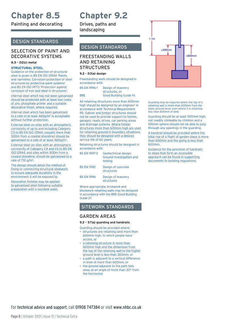
Guarding may be required where the top of a retaining wall is more than 600mm from the lower ground level, even where it is retaining less than 600mm of land.
Guarding should be at least 1100mm high, not readily climbable by children and a 100mm sphere should not be able to pass through any openings in the guarding.
A handrail should be provided where the total rise of a flight of garden steps is more than 600mm and the going is less than 600mm.
Guidance for the provision of handrails to steps that form an accessible approach can be found in supporting documents to building regulations.

Technical Extra | Issue 12 | October 2013 | Page 9
For technical advice and support, call 01908 747384 or visit www.nhbc.co.uk
GUIDANCE AND GOOD PRACTICE
GUIDANCE
Introducing Chapter 3.2 ‘Mechanical ventilation with heat recovery’
Who should read this: Technical and construction directors and managers, architects, designers, specialist suppliers and site managers.
Recent figures from industry, including a survey undertaken by NHBC’s inspectors, has shown that there has been a sudden and quite dramatic increase in the number of MVHR systems being installed in new homes. With emerging information linking indoor air quality to a range of health issues and new homes becoming ever-more airtight, it is vitally important to ensure that ventilation systems operate as intended and provide the correct level of ventilation.
Installing an MVHR system is one way of providing ventilation, with the additional benefit of reducing energy use; however, their in-service performance can be extremely sensitive to relatively minor installation defects. Fundamental to MVHR systems achieving satisfactory in-service performance is to ensure that appropriate standards are followed, not only for the on-site installation but, importantly, right at the start of the construction process – at the design stage.
INTRODUCTION
Recently, there has been a noticeable increase in the number of homes incorporating MVHR as the ventilation system, with current estimates suggesting that this could be around a quarter of new homes.
The need to ventilate homes correctly was highlighted in research from the NHBC Foundation in 2009, in Indoor air quality in highly energy efficient new homes – a review, followed by the publication this year of the Zero Carbon Hub-led VIAQ Task Group report Mechanical Ventilation with Heat Recovery in new homes. Both revealed a number of issues with MVHR systems.
Poorly designed and installed MVHR systems are likely to result in a lower quality of indoor air. But conversely, installed correctly, MVHR offers a practical solution to reducing energy use and providing appropriate ventilation. Correct detailing in the design of the system and ensuring that the design is accurately followed on site is paramount to achieving a system that works as intended.
Following the proven method of engaging with stakeholders, NHBC assembled a group of experts from
the ventilation and house-building industries, including representatives from several manufacturers of MVHR systems, a range of house builders, and academic and industry bodies. This group assessed the use of MVHR in house building, identified common problems and produced a set of technical standards to address them.
The outcome from this work is the new Chapter 3.2 'Mechanical ventilation with heat recovery', which will be included in the 2014 edition of the NHBC Standards. It documents new technical guidance that will not only set the standard for MVHR, but significantly raise it, to the benefit of homeowners and the industry in general.
The introduction of Chapter 3.2 ‘Mechanical ventilation with heat recovery’ represents a significant move forward in making sure MVHR systems operate correctly in accordance with our commitment to continually raise the standard of new homes.
YOU NEED TO… ■ Make sure that the design and installation of MVHR systems on your projects are fully compliant with the
new guidance set out in the new Chapter 3.2 ‘Mechanical ventilation with heat recovery’.

Page 10 | October 2013 | Issue 12 | Technical Extra
For technical advice and support, call 01908 747384 or visit www.nhbc.co.uk
GUIDANCE
MVHR – getting it right, from the start
Who should read this: Technical and construction directors and managers, architects, designers, specialist suppliers and site managers.
As the house-building industry starts to embrace MVHR, it is important that the best practice approach towards correctly designing and installing these systems is understood and applied.
Chapter 3.2 ‘Mechanical ventilation with heat recovery’ introduces benchmark standards for design, materials and sitework associated with MVHR systems, and this is supported by extensive technical guidance to help comply with the new standards. In this article, we take a look at a few of the key technical issues covered by the new Chapter and the rationale behind them.
INTRODUCTION
System design Satisfactory performance is dependent on the design taking into account issues such as the location of the fan unit, the type and position of air valves and terminals, and the control of condensation. As even relatively minor variations from the design can result in underperformance, it is important that what is designed is installed on site.
The designer should be asked to review any on-site variations to confirm whether the system will still perform satisfactorily. On-site variations might include changes to the specified materials, additional bends to ‘get round’ obstructions and changing the layout of ductwork.
Ductwork The type of duct and its airflow resistance needs to be integral to the design. The main types of duct used in domestic ventilation systems are rigid duct or semi-rigid duct with short, straight lengths of flexible duct – acceptable only for final connections. Compatibility between the duct and other components, such as bends, connectors and fixing brackets, is essential. To achieve the correct ventilation rate, airflow has to be balanced against the resistance of the ductwork system and its constituent components.
To reduce the risk of the system not performing satisfactorily, the components that make up a ductwork system should usually be from a single manufacturer and form part of a recognised system.
Although the airflow resistance of a ductwork system might vary between manufacturers and their products, the airflow resistance of rigid and semi-rigid duct can be measured, and the resultant figures used in the design. The airflow resistance of flexible ductwork is much more difficult to determine and can be much higher when compared with the other types
of duct. Therefore, flexible duct should only be used in straight lengths up to 300mm to make final connections with air valves and the fan unit.
Location of the fan unit MVHR systems require regular interaction from the occupants, which will involve ensuring that the system is maintained, such as regular cleaning/replacement of the filters, around twice a year. Filters are usually incorporated into the fan unit, which can be fairly large and difficult to locate. Because of the need to optimise space within the home, the fan unit is often located outside of the insulated envelope, typically in the roof void. While this may represent a good use of space, it does mean that additional measures need to be taken to ensure that the system performs as intended. Suitable access for maintenance should also be provided.
The minimum provision for access will usually be achieved by providing a suitable walkway from the roof void access to the fan unit and a 1m2 working platform.
Locating the MVHR fan unit outside of the insulated part of the home can have an effect on its performance. Whilst some fan units are fully insulated, others are not. It is important to ensure that the MVHR fan unit is suitable for its intended location and that the manufacturer’s recommendations for the proposed location are taken into account.
Over and above the need to insulate ductwork to prevent condensation formation, horizontal service ductwork installed outside of the insulated part of the home may require additional insulation to reduce heat transfer.
Prevention of condensation Ductwork may be carrying air that is at a different temperature to the surrounding atmosphere, and this
Technical Extra | Issue 12 | October 2013 | Page 11
For technical advice and support, call 01908 747384 or visit www.nhbc.co.uk
MVHR – getting it right, from the start
GUIDANCE (CONTINUED)
can create favourable conditions for condensation to form either on or in the ductwork. The new Chapter contains guidance for insulating ductwork that takes into account different types and functions of ducts, their location and where condensation might occur.
Building integrationIt is critical when considering MVHR as a ventilation system for new homes that these new benchmark standards are complied with. A well-considered strategy during the design stage – before procurement and commissioning – is essential, as is ensuring that the design is followed through to the installation.
Handover requirementsIn our efforts to design and install the system correctly, we must not forget the end user. It is vital that they are made fully aware of how the system works, in order for them to appreciate the importance of regular maintenance, such as cleaning the filters.
An information pack with easy-to-follow instructions detailing how to use and maintain the system should be provided on installation.
YOU NEED TO… ■ Ensure anyone involved in the design or installation of MVHR systems makes themselves familiar with the new
Chapter and what is required to comply with the new standards.
INFORMATION AND SUPPORT
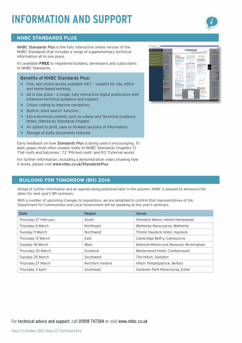
NHBC Standards Plus is the fully interactive online version of the NHBC Standards that includes a range of supplementary technical information all in one place.
It’s available FREE to registered builders, developers and subscribers to NHBC Standards.
Benefits of NHBC Standards Plus:nFree, fast online access available 24/7 – suitable for site, office
and home-based working.
nAll in one place – a single, fully interactive digital publication with extensive technical guidance and support.
nColour coding to improve navigation.
nBuilt-in ‘word search’ function.
nExtra technical content, such as videos and Technical Guidance Notes, filtered by Standards Chapter.
nAn option to print, save or forward sections of information.
nStorage of bulky documents reduced.
Early feedback on how Standards Plus is being used is encouraging. To date, pages most often viewed relate to NHBC Standards Chapters 7.1 ‘Flat roofs and balconies’, 7.2 ‘Pitched roofs’ and 9.2 ‘External works’.
For further information, including a demonstration video showing how it works, please visit www.nhbc.co.uk/StandardsPlus
NHBC STANDARDS PLUS
Ahead of further information and an agenda being published later in the autumn, NHBC is pleased to announce the dates for next year's Bft seminars.
With a number of upcoming changes to regulations, we are delighted to confirm that representatives of the Department for Communities and Local Government will be speaking at this year's seminars.
Date Region Venue
Thursday 27 February South Shendish Manor, Hemel Hempstead
Thursday 6 March Northeast Wetherby Racecourse, Wetherby
Tuesday 11 March Northwest Thistle Haydock Hotel, Haydock
Thursday 13 March East Cambridge Belfry, Cambourne
Tuesday 18 March West National Motorcycle Museum, Birmingham
Thursday 20 March Scotland Westerwood Hotel, Cumbernauld
Tuesday 25 March Southwest The Hilton, Swindon
Thursday 27 March Northern Ireland Hilton Templepatrick, Belfast
Thursday 3 April Southeast Sandown Park Racecourse, Esher
BUILDING FOR TOMORROW (Bft) 2014
Page 12 | October 2013 | Issue 12 | Technical Extra
For technical advice and support, call 01908 747384 or visit www.nhbc.co.uk

For technical advice and support, call 01908 747384 or visit www.nhbc.co.uk
INFORMATION AND SUPPORT
Free to download for registered builders/developers and professional subscribers to NHBC Standards, the Foundation Depth Calculator has been designed to give you a true field-based pocket tool to help you calculate the correct foundation depths when building near trees in clay soil.
Available on iOS and Windows OS, the app allows for changes in ground level, the input of an unlimited number of trees and an auto-climate zone depth-reduction function via GPS. It also advises on suitable heave precautions, if needed, and which tree(s) require them.
For more information, including a demonstration video, visit www.nhbc.co.uk/apps.
At the time of printing it is understood that final details of Part L 2013 are due to be announced immanently. The government has confirmed that transitional provisions for Part L 2013 will be the same as those for the 2010 regulations. For details of the transitional provisions, the latest information on what the new regulations will mean for you and NHBC events covering the changes please visit NHBC Techzone at www.nhbc.co.uk/techzone.
FOUNDATION DEPTH CALCULATOR APP
PART L 2013
Technical Extra | Issue 12 | October 2013 | Page 13
NHBC Foundation Report NF52: Assessment of MVHR systems and air quality in zero carbon homes.
This report is based on the experience of MVHR systems in 10 homes built by Scottish and Southern Energy at Greenwatt Way, Chalvey. Built to Code for Sustainable Homes level 6, these homes provided a perfect test bed for the detailed evaluation of MVHR systems in practice. As well as looking at design, specification, installation and commissioning issues, the research also gauged the use of these systems by some typical home occupants.
To read and download the report, please visit www.nhbcfoundation.org/MVHRsystems.
NHBC FOUNDATION REPORT ON MECHANICAL VENTILATION WITH HEAT RECOVERY (MVHR)

For technical advice and support, call 01908 747384 or visit www.nhbc.co.uk
NOTES:
Page 14 | October 2013 | Issue 12 | Technical Extra

For technical advice and support, call 01908 747384 or visit www.nhbc.co.uk
NOTES:
Technical Extra | Issue 12 | October 2013 | Page 15

NHBC, NHBC House, Davy Avenue, Knowlhill, Milton Keynes, Bucks MK5 8FP Tel: 0844 633 1000 Fax: 0844 633 0022 www.nhbc.co.uk
NHBC is authorised by the Prudential Regulation Authority and regulated by the Financial Conduct Authority and the Prudential Regulation Authority.
Copyright© NHBC 2013
This leaflet has been printed on material which is produced from well-managed forests and is fully recyclable and biodegradable, ECF (elemental chlorine free) and is made to ISO 14001 Environmental Certification.
HB2779 10/13
Useful contacts for technical information and advice
NHBC technical advice and supportTel: 01908 747384Email: [email protected]: www.nhbc.co.uk/builders/technicaladviceandsupport
Technical ExtraPrevious editions of Technical Extra are available on our website at www.nhbc.co.uk/Builders/ProductsandServices/TechnicalExtra/
NHBC StandardsBuy online at: www.nhbc.co.uk/nhbcshop/technicalstandards or access the new digital format Standards Plus via the NHBC Extranet at: www.nhbc.co.uk/builders/NHBCExtranet
Building RegulationsFor guidance on issues relating to Building Regulations, please visit NHBC’s TechZone at www.nhbc.co.uk/techzone
Building ControlFor Building Control queries, please call 0844 633 1000 and ask for ‘Building Control’, or email [email protected].
Engineering queriesFor Engineering queries, please call 0844 633 1000 and ask for ‘Engineering’.
NHBC Foundation researchThe NHBC Foundation facilitates research and shares relevant guidance and good practice with the house-building industry.
www.nhbcfoundation.org
TrainingFor information about training, please go to www.nhbc.co.uk/training, call 0844 633 1000 and ask for ‘Training’, or email [email protected].
The Zero Carbon HubThe UK Government has set out an ambitious plan for all new homes to be zero carbon from 2016. The Zero Carbon Hub helps you understand the challenges, issues and opportunities involved in developing, building and marketing your low and zero carbon homes.
www.zerocarbonhub.org
NHBC Clicks & Mortar e-newsletterNHBC regularly distributes information on a range of industry topics, including new products and services, the building industry market, house-building news and house-building statistics. To receive this industry information, please register at:
www.nhbc.co.uk/newsandcomment/registerfore-news
General enquiriesFor all other enquiries, including ordering products and services, please call 0844 633 1000, and ask for ‘Sales’.