NG-SONET and SDH
174
SONET/SDH and NG-SONET/SDH José M. Caballero
Transcript of NG-SONET and SDH
SONET/SDH and NG-SONET/SDH
José M. Caballero

SDH/SONET Next Generationii


Migration to Next Generation SDH José M. Caballero

ISBN 84-609-4420-4
© 2005 José M. Caballero-Artigas
No part of this book may be reproduced, stored in a retrieval system, or trans-mitted in any form or by any means, or by any means, electronic or mechani-cal without prior writing permission of the publisher.
Printed by Printulibro Intergrup, S.A.
Legal Deposit: B-8158-2005
Reprinted with corrections: 28 October 2015

To Abel, Iris, Manel and Ester


ix
Preface
For about 200,000 years, Neanderthal man inhabited and ruled the chilly forests and steppes of Eurasia. The Neanderthal society was gregarious and hierarchical, and it was formed by scattered tribes that brought up their children and took care of the wounded, the sick, and the elderly. The world view of these early human beings already showed signs of capacity for abstract and synthetic thinking, as they prac-ticed rites and decorated their bodies with necklaces, paintings, and earrings. Thanks to more than 2 million years of human evolution, they had their tools and techniques to make fire and procure and store food. They were also able to tan leather to make clothes and to protect their feet. But their weapons were what con-verted them into the most extraordinary predators in the food chain.
However, some 40,000 years ago, a new hominid species of African origin start-ed to compete for space with Homo Neanderthalensis. The newcomers were slightly different physically; their skin was darker and they were taller, although less mus-cular. This made them physically less prepared for the cold climate. They did not seem to be more intelligent either; at least if we look at the size of their skull, which was about 10% smaller than that of Neanderthal man. And if this is not enough, the children of this new species took twice as long to grow up; in this way forcing their parents to have fewer descendants. Evolution had made their reproductive period shorter, so that they could feed and take care of their descendants. In spite of all this, after a relatively short period of coexistence, Homo Neanderthalensis mysteriously disappeared. Perhaps they were just simply wiped away by their competitors, or killed by the new viruses coming from the south, or maybe they just disappeared be-cause they were unable to adapt themselves to the rapid changes between the Ice Ag-es. We do not know, but the newcomers known as Cromagnon man became dominants.
So, what was the key difference between Cromagnon and Neanderthal men?
Yes, communication. The unusual form of the larynx and the gullet of the new species, also known as Homo Sapiens, enabled them to generate and modulate so-phisticated sounds. Neanderthal men did not have this capacity, without which it is
Migration to Next Generation SDHx
impossible to create a human language. This theory explains how the hominids moved from waiting for genetic changes to using communication as the vital surviv-al tool. This proved to be more useful than the slow biological evolution in adapting the hominids to their environment. However, acquiring language skills and prepar-ing the brain for learning is a slow process that in this case made new generations mature more slowly, and parents had to spend more years taking care of their imma-ture descendants. Despite this, and other physiological difficulties, the new human beings who, as you probably already know, are nothing less than us, took over in a relatively short period of time, and ended up populating most of the planet.
The second significant milestone in the history of communications was the dis-covery of writing, probably the most important intellectual tool ever discovered by man. Writing enables us to store information and transmit it between two distant points and even between generations, without distorting or losing the message. There is evidence of earlier attempts, although the first effective form of writing was developed by the Sumerians about 5,000 years ago. The Sumerians lived in city-states on the banks of the Tigris and Euphrates rivers, where such activities as agri-culture, cattle raising, craft work, metallurgy, and construction flourished in an ex-traordinary way. Writing was born in the heart of these urban societies as a means to increase commerce, and solve both legal and social problems. Originally, the Sume-rian codes were iconographic, whereby each sign was an icon resembling the object it represented. This way, it was possible to sell or buy a herd of 53 lambs, for in-stance, or legally divide a property of 180 ikus of surface between heirs. When num-bers were later developed, this was a huge step forward, as it was no longer necessary to repeat the same icon a number of times. But what really made a change was the invention of the phonetic writing system. Now it was possible to describe battles or the position of stars, or write down laws, such as Hammurabi’s Code of Law.
This was the start of our civilization.
For thousands of years, writing was done by hand on clay, stones, papyrus, or leather, until in 1450 the workshop of Gutenberg started to mechanically produce what became the first books. Fifty years later, the few books kept in monasteries and palaces were transformed into more than 10 million volumes. It was finally possible to store and produce a large amount of information at lower cost than before, and without changing the original contents. Knowledge, literature, and science were no longer tools of power for a small elite of scribes, priests, and courtiers. This way, by having the medium to broadcast information to thousands of recipients, the printing industry had an important role in marking the end of the dark Middle Ages.
Some centuries had to pass before electricity was managed in such a way that the first telephone patented by Alexander Graham Bell in 1876 could be developed.
Preface xi
A few years later, around 1900, the first radio transmissions took place, and televi-sion appeared in the 1930s. Without underestimating television, there is something that makes the telephone special, in that it enables direct interpersonal communica-tion at a distance. We can even see the telephone as an extension of our larynx and ears, while radio and television are one-way media, where the receiver can only con-nect and disconnect, the same way as you can close this book, but not modify its con-tents. This difference is notable, and it explains why both radio and TV tend to be desired, controlled and even manipulated by political, economical or religious pow-er, while private telephone conversations offer more liberty and independence. The telephone is by definition a tool where the contents, the language, and the recipient can be decided by the users themselves.
Finally, we arrive at the mid-1990s, when the Internet became an important me-dium for mass communication. It combines two fundamental inventions: writing and telecommunications. Writing can be very precise and it enables us to store informa-tion, crossing the time barrier; while telecommunications overcomes space barriers. It is so efficient that many times we prefer to send electronic messages even within the same office, although it would be easier just to have a short conversation. But the Internet is a lot more than an efficient two-way communication medium. It is also a way to access the immense “universal library,” with an impact that can only be com-pared to the Alexandria Library 2,000 years ago. In the Internet, we have millions of documents with information that can be reached from any part of the world in just a few seconds.
The third generation wireless networks will also bring some changes in the near future, by improving the human-machine relationship. Our mobile telephones will become terminals with Internet access or radio and video broadcast, accessible from anywhere in the world with reasonable costs. During the next years, our written works, both in the office and at home, will depend less and less on paper. There will be a need for new devices to substitute for paper. These devices should be connect-able, autonomous, light, easy to handle, and shock-proof. With a resolution of about 300 dots per inch we could read our newspaper in the train or read a book in the gar-den as comfortably as before, but saving the cost of cutting tons of wood and using chemical substances to make paper. In other words, human evolution and globaliza-tion is a communication matter as old as mankind. Therefore human interaction and multiculturalism are accelerated whenever a new communication milestone is reached, such as the larynx, the art of writing, the printing press, the telephone, radio, television, or the Internet.
José M. Caballero
England, April 2005

Migration to Next Generation SDHxii
Contents
................................................................................................................ ixPreface .................................................................................................... ix
Chapter 1 PDH and T-Carrier: The Plesiochronous Hierarchies....... 1
1.1 An Introduction to Communications Systems.................................11.1.1 Signals and Information ......................................................11.1.2 Transmission Medium .........................................................21.1.3 Channel Coding ...................................................................71.1.4 Multiplexing and Multiple Access ......................................10
1.2 Pulse Code Modulation ...................................................................11
1.3 PDH and T-Carrier...........................................................................131.3.1 Basic Rates: T1 and E1 .......................................................14
1.4 The E1 Frame ..................................................................................151.4.1 Frame Alignment .................................................................151.4.2 Frame Alignment Signal ......................................................161.4.3 Multiframe CRC-4 ...............................................................161.4.4 Supervision Bits ...................................................................181.4.5 NFASs - Spare Bits .............................................................191.4.6 NFAS - Alarm Bit ...............................................................191.4.7 Signaling Channel ...............................................................201.4.8 CAS Signaling Multiframe ..................................................20
1.5 The Plesiochronous Digital Hierarchy ............................................221.5.1 Higher Hierarchical Levels ..................................................231.5.2 Multiplexing Level 2: 8 Mbps .............................................231.5.3 Multiplexing Level 3: 34 Mbps ...........................................241.5.4 Multiplexing Level 4: 140 Mbps .........................................241.5.5 Service Bits in Higher Level Frames ...................................241.5.6 Plesiochronous Synchronization .........................................261.5.7 Positive Justification ............................................................27
1.6 Managing Alarms in Higher Level Hierarchies ..............................28
1.7 The T-Carrier Hierarchy ..................................................................291.7.1 The DS1 Frame ....................................................................291.7.2 The DS2 Frame ....................................................................32
Contents
xiv
1.7.3 The DS3 Frame ................................................................... 32
Selected Bibliography ............................................................................ 33
Chapter 2 Classic SDH/SONET..............................................................35
2.1 The Emergence of SDH/SONET Networks.................................... 352.1.1 Limitations of Plesiochronous Networks ............................ 352.1.2 The SDH/SONET Challenge .............................................. 37
2.2 Comparison of SDH and SONET ................................................... 39
2.3 Functional Architecture................................................................... 402.3.1 Network Elements ............................................................... 402.3.2 Network Topology .............................................................. 412.3.3 Topology Partitioning ......................................................... 422.3.4 SDH/SONET Layers ........................................................... 42
2.4 SDH/SONET Formats and Procedures ........................................... 452.4.1 SDH/SONET Frame Structure ............................................ 462.4.2 Multiplexing Map ............................................................... 49
2.5 SDH Transport Services.................................................................. 49
2.6 Transporting PDH/T-Carrier Tributaries ......................................... 532.6.1 Transport on VC-4 or STS-3c SPE ..................................... 542.6.2 Transport on VC-3 .............................................................. 552.6.3 Transport of 2-Mbps Circuits .............................................. 57
2.7 Pointers and Timing Compensation ................................................ 602.7.1 Payload Synchronization ..................................................... 602.7.2 Pointer Formats and Procedures ......................................... 61
2.8 Overheads........................................................................................ 642.8.1 Path Overhead ..................................................................... 662.8.2 Section Overhead ................................................................ 672.8.3 The SDH/SONET Hierarchy .............................................. 69
2.9 Concatenation.................................................................................. 71
2.10Maintenance .................................................................................... 722.10.1 SDH/SONET Events ......................................................... 722.10.2 Monitoring Events ............................................................. 752.10.3 Event Tables ...................................................................... 75
2.11 Performance Monitoring ................................................................. 782.11.1 Bit Error Checking ............................................................ 782.11.2 Tandem Connection Monitoring ....................................... 792.11.3 Forward Error Correction .................................................. 79
2.12Defects ............................................................................................ 80
2.13SDH Resilience ............................................................................... 832.13.1 Protection Basics ............................................................... 842.13.2 Multiplex Section or Line Protection ................................ 87
2.14Operation, Administration, and Management................................. 912.14.1 The TMN Standard ........................................................... 912.14.2 TMN Benefits ................................................................... 92
xv
Selected Bibliography.............................................................................93
Chapter 3 SDH/SONET Next Generation............................................. 95
3.1 Streaming forces ..............................................................................95
3.2 Legacy and Next Generation SDH ..................................................963.2.1 Evolution of the Transmission Network ..............................96
3.3 The Next Generation Challenge ......................................................963.3.1 Virtual Concatenation ..........................................................973.3.2 The New Network Elements ...............................................98
3.4 Core transport Services....................................................................993.4.1 Next-Generation SDH .........................................................99
3.5 Generic Framing Protocol ...............................................................1003.5.1 Framed–Mapped GFP .........................................................1033.5.2 Transparent GFP ..................................................................103
3.6 Concatenation ..................................................................................1053.6.1 Contiguous Concatenation of VC-4 ....................................1063.6.2 Virtual Concatenation ..........................................................1073.6.3 VCAT Setup ........................................................................112
3.7 Link Capacity Adjustment Scheme .................................................1123.7.1 LCAS Protocol ....................................................................1123.7.2 Light over LCAS .................................................................1133.7.3 LCAS Applications .............................................................1173.7.4 NG SDH Event Tables ........................................................120
3.8 Conclusions .....................................................................................121
Selected Bibliography.............................................................................122
Chapter 4 Network Synchronization ..................................................... 125
4.1 Architecture of Synchronization Networks .....................................1254.1.1 Synchronization Network Topologies .................................127
4.2 Interconnection of Nodes ................................................................1294.2.1 Synchronization Signals ......................................................1294.2.2 Holdover Mode ....................................................................1314.2.3 Global Positioning System ..................................................131
4.3 Disturbances in Synchronization Signals ........................................1324.3.1 Frequency Offset .................................................................1324.3.2 Phase Fluctuation .................................................................134
4.4 Synchronization of Transmission Networks....................................1374.4.1 Synchronization in SONET and SDH .................................1384.4.2 Synchronization Models ......................................................1394.4.3 Timing Loops ......................................................................141
4.5 Digital Synchronization and Switching...........................................141
4.6 SSU in a Synchronization Network.................................................1434.6.1 Functions of SSU .................................................................144

xvi
Selected Bibliography ............................................................................ 145
1
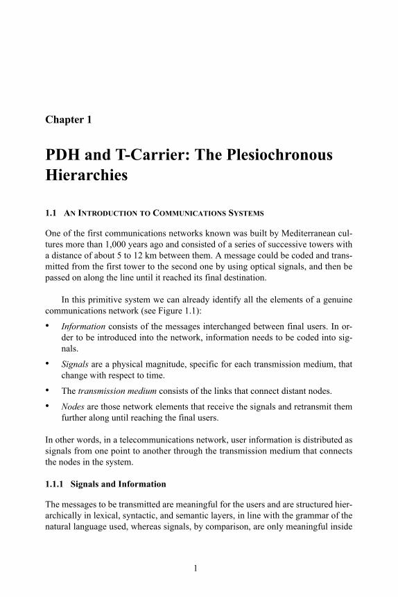
Chapter 1
PDH and T-Carrier: The Plesiochronous Hierarchies
1.1 AN INTRODUCTION TO COMMUNICATIONS SYSTEMS
One of the first communications networks known was built by Mediterranean cul-tures more than 1,000 years ago and consisted of a series of successive towers with a distance of about 5 to 12 km between them. A message could be coded and trans-mitted from the first tower to the second one by using optical signals, and then be passed on along the line until it reached its final destination.
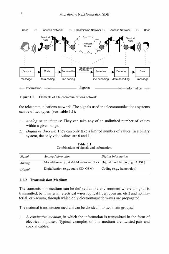
In this primitive system we can already identify all the elements of a genuine communications network (see Figure 1.1):
• Information consists of the messages interchanged between final users. In or-der to be introduced into the network, information needs to be coded into sig-nals.
• Signals are a physical magnitude, specific for each transmission medium, that change with respect to time.
• The transmission medium consists of the links that connect distant nodes.
• Nodes are those network elements that receive the signals and retransmit them further along until reaching the final users.
In other words, in a telecommunications network, user information is distributed as signals from one point to another through the transmission medium that connects the nodes in the system.
1.1.1 Signals and Information
The messages to be transmitted are meaningful for the users and are structured hier-archically in lexical, syntactic, and semantic layers, in line with the grammar of the natural language used, whereas signals, by comparison, are only meaningful inside
Migration to Next Generation SDH2
the telecommunications network. The signals used in telecommunications systems can be of two types (see Table 1.1):
1. Analog or continuous: They can take any of an unlimited number of values within a given range.
2. Digital or discrete: They can only take a limited number of values. In a binary system, the only valid values are 0 and 1.
1.1.2 Transmission Medium
The transmission medium can be defined as the environment where a signal is transmitted, be it material (electrical wires, optical fiber, open air, etc.) and nonma-terial, or vacuum, through which only electromagnetic waves are propagated.
The material transmission medium can be divided into two main groups:
1. A conductive medium, in which the information is transmitted in the form of electrical impulses. Typical examples of this medium are twisted-pair and coaxial cables.
Table 1.1Combinations of signals and information.
Signal Analog Information Digital Information
Analog Modulation (e.g., AM/FM radio and TV) Digital modulation (e.g., ADSL)
Digital Digitalization (e.g., audio CD, GSM) Coding (e.g., frame relay)
Figure 1.1 Elements of a telecommunications network.
Source SinkCoder DecoderTransmitter Receiver
line coding
Transmissionmedium
line decoding data decodingdata codingmessage message
Terminal Node
Terminal Node
Network Nodes
Access Network Access NetworkTransmission Network
InformationSignalsInformation
UserUser
PDH and T-Carrier: The Plesiochronous Hierarchies 3
2. A dielectric medium, in which the information is transmitted in the form of radioelectrical or optical signals; for example, the atmosphere and optical fiber.
Transmitted signal
Attenuation
Distortion
Noise
Received signal
SourceTransmitter
Tra
nsm
issi
on m
ediu
mReceiver Sink
dist
anc
e (
d)
PTx
PRx
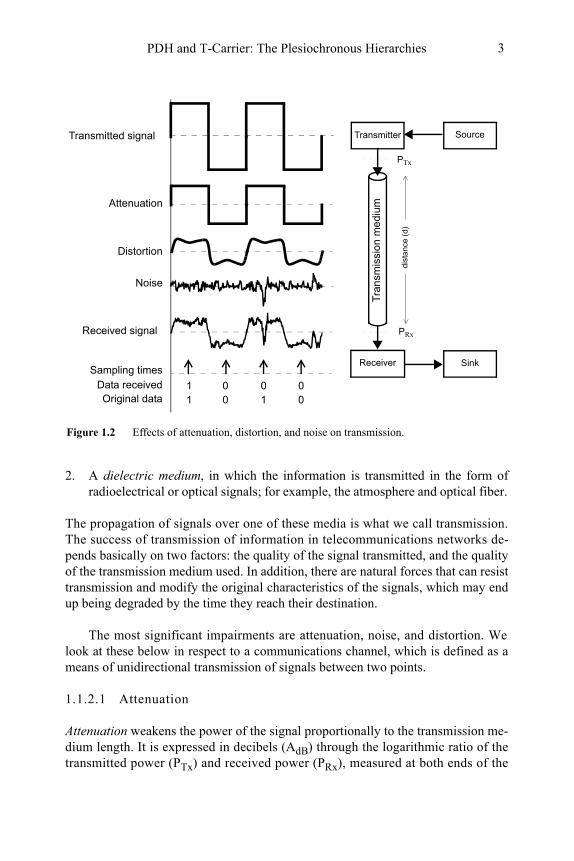
Figure 1.2 Effects of attenuation, distortion, and noise on transmission.
Sampling timesData receivedOriginal data
1 0 0 01 0 1 0
The propagation of signals over one of these media is what we call transmission. The success of transmission of information in telecommunications networks de-pends basically on two factors: the quality of the signal transmitted, and the quality of the transmission medium used. In addition, there are natural forces that can resist transmission and modify the original characteristics of the signals, which may end up being degraded by the time they reach their destination.
The most significant impairments are attenuation, noise, and distortion. We look at these below in respect to a communications channel, which is defined as a means of unidirectional transmission of signals between two points.
1.1.2.1 Attenuation
Attenuation weakens the power of the signal proportionally to the transmission me-dium length. It is expressed in decibels (AdB) through the logarithmic ratio of the transmitted power (PTx) and received power (PRx), measured at both ends of the
Migration to Next Generation SDH4
distance (d) being examined (see Figure 1.2). Transmission media can usually be characterized by their attenuation per unit of length (AdB / Km):
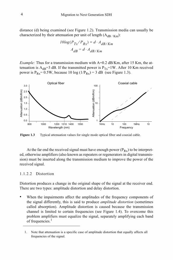
Example: Thus for a transmission medium with A=0.2 dB/Km, after 15 Km, the at-tenuation is AdB=3 dB. If the transmitted power is PTx=1W. After 10 Km received power is PRx= 0.5W, because 10 log (1/PRx) = 3 dB (see Figure 1.3).
At the far end the received signal must have enough power (PRx) to be interpret-ed, otherwise amplifiers (also known as repeaters or regenerators in digital transmis-sion) must be inserted along the transmission medium to improve the power of the received signal.
1.1.2.2 Distortion
Distortion produces a change in the original shape of the signal at the receiver end. There are two types: amplitude distortion and delay distortion.
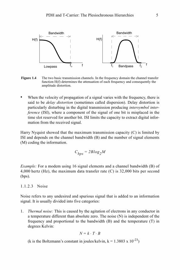
• When the impairments affect the amplitudes of the frequency components of the signal differently, this is said to produce amplitude distortion (sometimes called absorption). Amplitude distortion is caused because the transmission channel is limited to certain frequencies (see Figure 1.4). To overcome this problem amplifiers must equalize the signal, separately amplifying each band of frequencies.1
1. Note that attenuation is a specific case of amplitude distortion that equally affects all frequencies of the signal.
10 PTx PRx⁄( )log d AdB Km⁄⋅=
AdB d A⋅ dB Km⁄=
0.0
0.5
1.0
2.5
3.0
101000 1310 1400 1550
Wavelength (nm)
Atte
nu
atio
n (d
Bm
/Km
)
2.5
1.5
Figure 1.3 Typical attenuation values for single mode optical fiber and coaxial cable.
1
100
Att
en
uatio
n (
dB
m/K
m)
10
1200 1KHz 100 1MHz 10
Frequency800
Optical fiber Coaxial cable
PDH and T-Carrier: The Plesiochronous Hierarchies 5
• When the velocity of propagation of a signal varies with the frequency, there is said to be delay distortion (sometimes called dispersion). Delay distortion is particularly disturbing in the digital transmission producing intersymbol inter-ference (ISI), where a component of the signal of one bit is misplaced in the time slot reserved for another bit. ISI limits the capacity to extract digital infor-mation from the received signal.
Harry Nyquist showed that the maximum transmission capacity (C) is limited by ISI and depends on the channel bandwidth (B) and the number of signal elements (M) coding the information.
Example: For a modem using 16 signal elements and a channel bandwidth (B) of 4,000 hertz (Hz), the maximum data transfer rate (C) is 32,000 bits per second (bps).
1.1.2.3 Noise
Noise refers to any undesired and spurious signal that is added to an information signal. It is usually divided into five categories:
1. Thermal noise: This is caused by the agitation of electrons in any conductor in a temperature different than absolute zero. The noise (N) is independent of the frequency and proportional to the bandwidth (B) and the temperature (T) in degrees Kelvin:
N k T B⋅ ⋅=
(k is the Boltzmann’s constant in joules/kelvin, k = 1.3803 x 10⁻²³)
Figure 1.4 The two basic transmission channels. In the frequency domain the channel transfer function H(f) determines the attenuation of each frequency and consequently the amplitude distortion.
fffo f2f1
Bandwidth Bandwidth
H(f)H(f)
Lowpass Bandpass
Cbps 2Blog2M=
Migration to Next Generation SDH6
2. Intermodulation noise: This is caused when two or more signals of frequencies f1 and f2, transmitted in the same medium, produce a spurious signal at fre-quencies that are a linear combination of the previous ones.
3. Atmospheric noise: This is caused by the static discharge of clouds, or ionized gas from the sun, or high frequency signals radiated by the stars.
4. Impulse noise: Of short duration but high amplitude, these energy bursts are caused by sources such as electrical machinery, a drop in voltage, atmospheric interference, and so on. These do not tend to be a problem for analog signals, but are a prime cause of errors in digital transmission.
5. Crosstalk: Whenever a current flows through a conductor a magnetic field is set up around it that can induct a current into a second conductor collocated in a short distance.
Noise is always present in transmission channels, even when no signal is being transmitted. A key parameter at the receiver end to distinguish between information and spurious power is the signal-to-noise ratio (S/N):
Claude Shannon proved that the signal-to-noise ratio (S/N) determines the the-oretical maximum transmission capacity (C) in bits per second of channel with a lim-ited bandwidth (B):
Example: A typical value of S/N for a voice grade line is 30 dB (equivalent to a power ratio of 1,000:1). Thus for a bandwidth of 3,100 Hz the maximum data trans-fer rate (C) should be 30,894 bps.
If we pay attention only to the Nyquist formula (see Section 1.1.2.2) we could inaccurately conclude that for a given bandwidth (B) the data rate can be increased endlessly, by increasing the number of signal elements. However in reality, the sig-nal-to-noise ratio sets up the theoretical limit of the channel capacity.
The Shannon theorem makes no statement as to how the channel capacity is achieved. In fact, channels only approach this limit. The task of providing high chan-nel efficiency is the goal of coding techniques.
S N⁄( )dB 10 PowerSignal PowerNoise⁄( )log=
Cbps Blog2 1 S N⁄+( )=
PDH and T-Carrier: The Plesiochronous Hierarchies 7
1.1.2.4 The transmission channel
A digital channel is a communication subsystem with capacity to send and receive information between two points: a source and a sink. Related concepts are:
• Bandwidth, expressed in hertz (Hz). This is the difference between the highest and the lowest frequency that can be transmitted across a line or a network.
• Data rate, expressed in bits per second (bps). This is a measure of the speed with which information is transferred. It depends on the bandwidth, transmis-sion medium impairments, and the technological capacity to efficiently use the available bandwidth.
• Performance, expressed in bit error rate (BER). This is the probability of a sin-gle bit being corrupted in a defined interval. Performance is on indication of the quality of the channel.
Channel capacity is the data rate that can be transmitted over a communication path under specific conditions.When two channels define a two-way communication, it is more usual to talk about a circuit.
1.1.3 Channel Coding
Channel coding is the process that transforms binary data bits into signal elements that can cross the transmission medium. In the simplest case, in a metallic wire a bi-nary 0 is represented by a lower voltage, and a binary 1 by a higher voltage. How-ever, before selecting a coding scheme it is necessary to identify some of the strengths and weaknesses of line codes:
• High-frequency components are not desirable because they require more chan-nel bandwidth, suffer more attenuation, and generate crosstalk in electrical links.
• Direct current (dc) components should be avoided because they require physi-cal coupling of transmission elements. Since the earth/ground potential usually varies between remote communication ends, dc provokes unwanted earth-re-turn loops.
• The use of alternating current (ac) signals permits a desirable physical isola-tion using condensers and transformers.
• Timing control permits the receiver to correctly identify each bit in the trans-mitted message. In synchronous transmission, the timing is referenced to the transmitter clock, which can be sent as a separate clock signal, or embedded into the line code. If the second option is used, then the receiver can extract its clock from the incoming data stream thereby avoiding the installation of an ad-ditional line.
Migration to Next Generation SDH8
In order to meet these requirements, line coding is needed before the signal is trans-mitted, along with the corresponding decoding process at the receiving end. There are a number of different line codes that apply to digital transmission, the most widely used ones are alternate mark inversion (AMI), high-density bipolar three ze-ros (HDB3), and coded mark inverted (CMI).
1.1.3.1 Non-return to zero
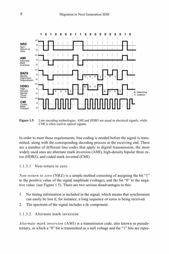
Non-return to zero (NRZ) is a simple method consisting of assigning the bit “1” to the positive value of the signal amplitude (voltage), and the bit “0” to the nega-tive value (see Figure 1.5). There are two serious disadvantages to this:
1. No timing information is included in the signal, which means that synchronism can easily be lost if, for instance, a long sequence of zeros is being received.
2. The spectrum of the signal includes a dc component.
Figure 1.5 Line encoding technologies. AMI and HDB3 are usual in electrical signals, while CMI is often used in optical signals.
0
B8ZS
HDB3
CMI
0
+V
-V
0
+V
-V
0
+V
-V
0
+V
-V
0 0 0 V
B 0 0 V
B 0 0 V
BipolarEight-ZeroSuppression
HighDensityBipolarThreeZeros
CodedMarkInverted
B: balancingV: violation
NRZ 0
+V
-VNon- Return toZero
AMIAlternateMarkInversion
- 0 0 0 V + 0
0 1 0 0 01 1 1 0 0 0 00 0 0 0 1 0
V -
1.1.3.2 Alternate mark inversion
Alternate mark inversion (AMI) is a transmission code, also known as pseudo-ternary, in which a “0” bit is transmitted as a null voltage and the “1” bits are repre-
PDH and T-Carrier: The Plesiochronous Hierarchies 9
sented alternately as positive and negative voltage. The digital signal coded in AMI is characterized as follows (see Figure 1.5):
• The dc component of its spectrum is null.
• It does not solve the problem of loss of synchronization with long sequences of zeros.
1.1.3.3 Bit eight-zero suppression
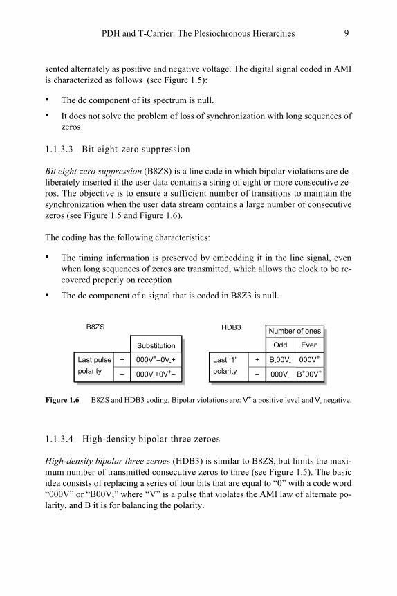
Bit eight-zero suppression (B8ZS) is a line code in which bipolar violations are de-liberately inserted if the user data contains a string of eight or more consecutive ze-ros. The objective is to ensure a sufficient number of transitions to maintain the synchronization when the user data stream contains a large number of consecutive zeros (see Figure 1.5 and Figure 1.6).
The coding has the following characteristics:
• The timing information is preserved by embedding it in the line signal, even when long sequences of zeros are transmitted, which allows the clock to be re-covered properly on reception
• The dc component of a signal that is coded in B8Z3 is null.
1.1.3.4 High-density bipolar three zeroes
High-density bipolar three zeroes (HDB3) is similar to B8ZS, but limits the maxi-mum number of transmitted consecutive zeros to three (see Figure 1.5). The basic idea consists of replacing a series of four bits that are equal to “0” with a code word “000V” or “B00V,” where “V” is a pulse that violates the AMI law of alternate po-larity, and B it is for balancing the polarity.
Figure 1.6 B8ZS and HDB3 coding. Bipolar violations are: V+ a positive level and V- negative.
+
–
Last pulse
polarity
B8ZS Number of ones
B-00V-+
–
Last ‘1’
polarity
HDB3
000V- B+00V+
000V+
Odd EvenSubstitution
000V+–0V-+
000V-+0V+–
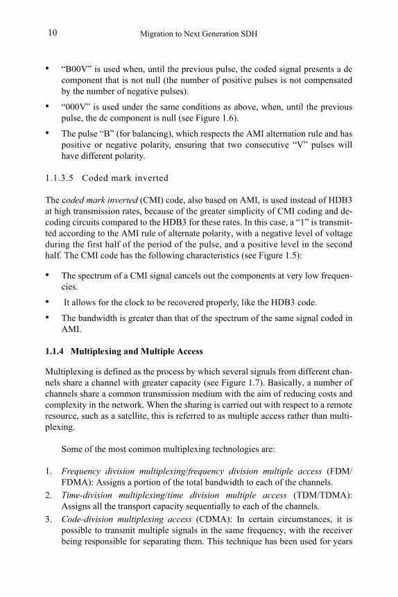
Migration to Next Generation SDH10
• “B00V” is used when, until the previous pulse, the coded signal presents a dc component that is not null (the number of positive pulses is not compensated by the number of negative pulses).
• “000V” is used under the same conditions as above, when, until the previous pulse, the dc component is null (see Figure 1.6).
• The pulse “B” (for balancing), which respects the AMI alternation rule and has positive or negative polarity, ensuring that two consecutive “V” pulses will have different polarity.
1.1.3.5 Coded mark inverted
The coded mark inverted (CMI) code, also based on AMI, is used instead of HDB3 at high transmission rates, because of the greater simplicity of CMI coding and de-coding circuits compared to the HDB3 for these rates. In this case, a “1” is transmit-ted according to the AMI rule of alternate polarity, with a negative level of voltage during the first half of the period of the pulse, and a positive level in the second half. The CMI code has the following characteristics (see Figure 1.5):
• The spectrum of a CMI signal cancels out the components at very low frequen-cies.
• It allows for the clock to be recovered properly, like the HDB3 code.
• The bandwidth is greater than that of the spectrum of the same signal coded in AMI.
1.1.4 Multiplexing and Multiple Access
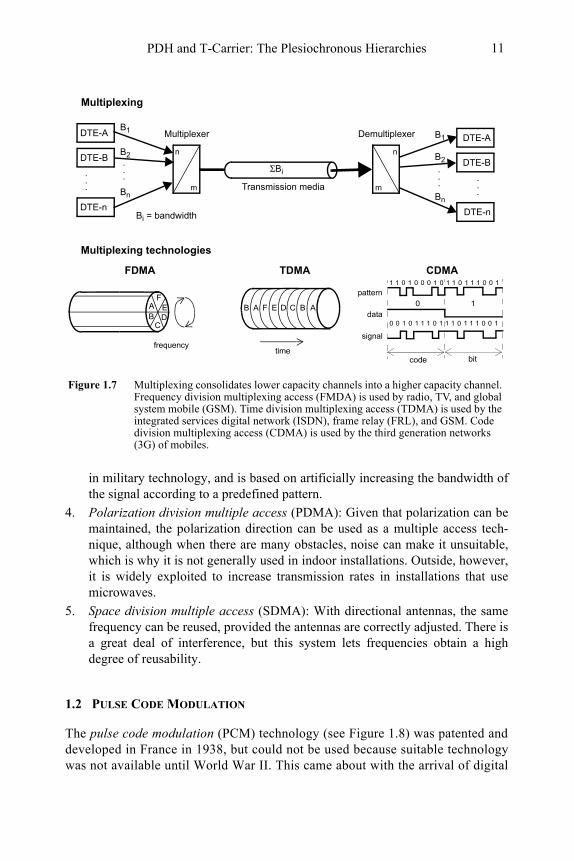
Multiplexing is defined as the process by which several signals from different chan-nels share a channel with greater capacity (see Figure 1.7). Basically, a number of channels share a common transmission medium with the aim of reducing costs and complexity in the network. When the sharing is carried out with respect to a remote resource, such as a satellite, this is referred to as multiple access rather than multi-plexing.
Some of the most common multiplexing technologies are:
1. Frequency division multiplexing/frequency division multiple access (FDM/FDMA): Assigns a portion of the total bandwidth to each of the channels.
2. Time-division multiplexing/time division multiple access (TDM/TDMA): Assigns all the transport capacity sequentially to each of the channels.
3. Code-division multiplexing access (CDMA): In certain circumstances, it is possible to transmit multiple signals in the same frequency, with the receiver being responsible for separating them. This technique has been used for years
PDH and T-Carrier: The Plesiochronous Hierarchies 11
in military technology, and is based on artificially increasing the bandwidth of the signal according to a predefined pattern.
4. Polarization division multiple access (PDMA): Given that polarization can be maintained, the polarization direction can be used as a multiple access tech-nique, although when there are many obstacles, noise can make it unsuitable, which is why it is not generally used in indoor installations. Outside, however, it is widely exploited to increase transmission rates in installations that use microwaves.
5. Space division multiple access (SDMA): With directional antennas, the same frequency can be reused, provided the antennas are correctly adjusted. There is a great deal of interference, but this system lets frequencies obtain a high degree of reusability.
1.2 PULSE CODE MODULATION
The pulse code modulation (PCM) technology (see Figure 1.8) was patented and developed in France in 1938, but could not be used because suitable technology was not available until World War II. This came about with the arrival of digital
DTE-AB1
DTE-BB2
DTE-n
Bn
.
.
.
Figure 1.7 Multiplexing consolidates lower capacity channels into a higher capacity channel. Frequency division multiplexing access (FMDA) is used by radio, TV, and global system mobile (GSM). Time division multiplexing access (TDMA) is used by the integrated services digital network (ISDN), frame relay (FRL), and GSM. Code division multiplexing access (CDMA) is used by the third generation networks (3G) of mobiles.
AAB
CDE
FBCDEFAB
TDMAFDMA
time
0 0 1 0 1 1 1 0 1 1 1 0 1 1 1 0 0 1
1 1 0 1 0 0 0 1 0 1 1 0 1 1 1 0 0 1
code bit
CDMA
frequency
DTE-AB1
DTE-BB2
DTE-n
Bn
.
.
. Transmission media
ΣBi
n
m
n
m
Multiplexer Demultiplexer
Multiplexing
Bi = bandwidth
.
.
.
.
.
.
Multiplexing technologies
pattern
data
signal
0 1
Migration to Next Generation SDH12
systems in the 1960s, when improving the performance of communications net-works became a real possibility. However, this technology was not completely ad-opted until the mid-1970s, due to the large amount of analog systems already in place and the high cost of digital systems, as semiconductors were very expensive. PCM’s initial goal was that of converting an analog voice telephone channel into a digital one based on the sampling theorem (see Figure 1.9):
The sampling theorem states that for digitalization without information loss, the sampling frequency (fs) should be at least twice the maximum frequency component (fmax) of the analog information:
The frequency 2·fmax is called the Nyquist sampling rate. The sampling theorem is considered to have been articulated by Nyquist in 1928, and mathematically prov-en by Shannon in 1949. Some books use the term Nyquist sampling theorem, and others use Shannon sampling theorem. They are in fact the same theorem.
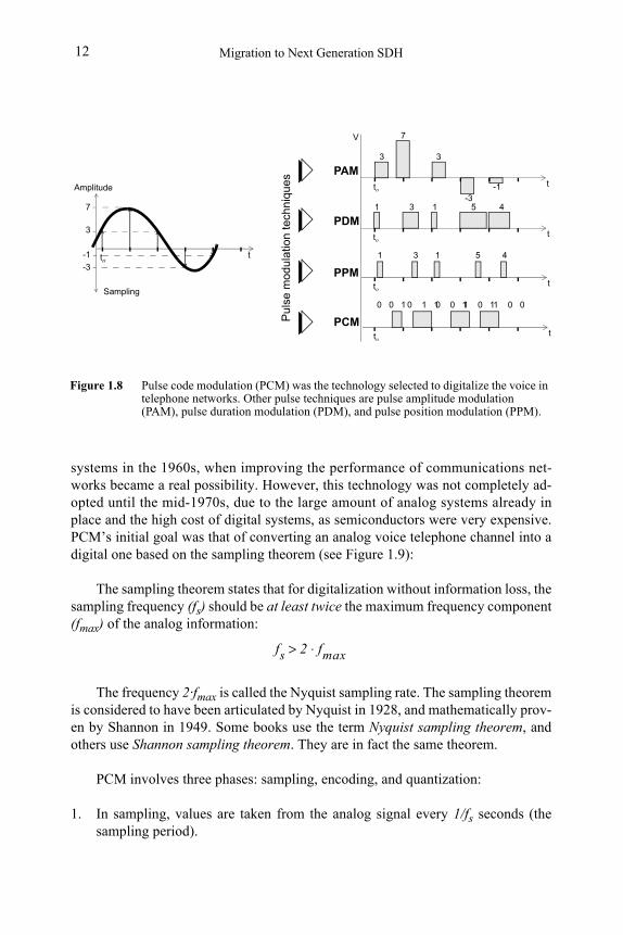
PCM involves three phases: sampling, encoding, and quantization:
1. In sampling, values are taken from the analog signal every 1/fs seconds (the sampling period).
Figure 1.8 Pulse code modulation (PCM) was the technology selected to digitalize the voice in telephone networks. Other pulse techniques are pulse amplitude modulation (PAM), pulse duration modulation (PDM), and pulse position modulation (PPM).
PAM3
7
3
-3-1to
PDM1 3 1 5 4
t
tot
PPMto
t
tot
PCM
1 3 1 5 4
0 1 10 0 1 0 0 11 0 11 0 0
Amplitude
Sampling
to t
7
3
-1
-3
V
Pul
se m
odul
atio
n te
chni
ques
fs 2 f⋅ max>
PDH and T-Carrier: The Plesiochronous Hierarchies 13
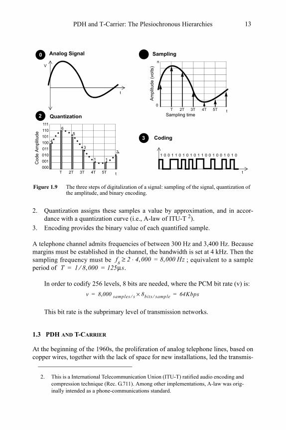
2. Quantization assigns these samples a value by approximation, and in accor-dance with a quantization curve (i.e., A-law of ITU-T 2).
3. Encoding provides the binary value of each quantified sample.
A telephone channel admits frequencies of between 300 Hz and 3,400 Hz. Because margins must be established in the channel, the bandwidth is set at 4 kHz. Then the sampling frequency must be ; equivalent to a sample period of .
In order to codify 256 levels, 8 bits are needed, where the PCM bit rate (v) is:
This bit rate is the subprimary level of transmission networks.
1.3 PDH AND T-CARRIER
At the beginning of the 1960s, the proliferation of analog telephone lines, based on copper wires, together with the lack of space for new installations, led the transmis-
2. This is a International Telecommunication Union (ITU-T) ratified audio encoding and compression technique (Rec. G.711). Among other implementations, A-law was orig-inally intended as a phone-communications standard.
Figure 1.9 The three steps of digitalization of a signal: sampling of the signal, quantization of the amplitude, and binary encoding.
Am
plit
ud
e (
volts
)
0
Sampling timeT
n
Sampling
2T
Co
de A
mp
litu
de
1
Quantization
1
23
56
4
Analog Signal
000
001
011
101
111
010
100
110
Coding
t
t
t
1 1 1 1 1 1 1 1 1 10 0 0 0 0 0 0 0 0 0 0
0 1
2
3
3T 4T 5T
V
T 2T t3T 4T 5T
fs 2 4 000, 8 000,= Hz⋅≥T 1 8 000, 125μs=⁄=
v 8 000, samples s⁄ 8bits sample⁄× 64Kbps= =
Migration to Next Generation SDH14
sion experts to look at the real application of PCM digitalization techniques and TDM multiplexing. The first digital communications system was set up by Bell Labs in 1962, and consisted of 24 digital channels running at what is known as T1.
1.3.1 Basic Rates: T1 and E1
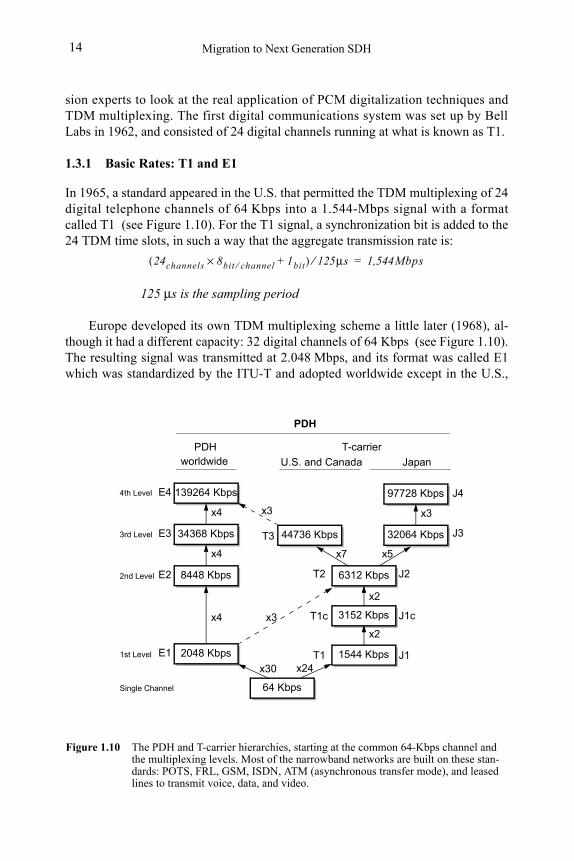
In 1965, a standard appeared in the U.S. that permitted the TDM multiplexing of 24 digital telephone channels of 64 Kbps into a 1.544-Mbps signal with a format called T1 (see Figure 1.10). For the T1 signal, a synchronization bit is added to the 24 TDM time slots, in such a way that the aggregate transmission rate is:
125 μs is the sampling period
Europe developed its own TDM multiplexing scheme a little later (1968), al-though it had a different capacity: 32 digital channels of 64 Kbps (see Figure 1.10). The resulting signal was transmitted at 2.048 Mbps, and its format was called E1 which was standardized by the ITU-T and adopted worldwide except in the U.S.,
139264 Kbps
34368 Kbps
8448 Kbps
97728 Kbps
6312 Kbps
Figure 1.10 The PDH and T-carrier hierarchies, starting at the common 64-Kbps channel and the multiplexing levels. Most of the narrowband networks are built on these stan-dards: POTS, FRL, GSM, ISDN, ATM (asynchronous transfer mode), and leased lines to transmit voice, data, and video.
139264 Kbps
x4
34368 Kbps
x4
8448 Kbps
x4
2048 Kbps
64 Kbps
1544 Kbps
x2
44736 Kbps 32064 Kbps
97728 Kbps
x3
x30 x24
x3
x7 x5
x3
4th Level
3rd Level
2nd Level
PDH T-carrier
Japan
Single Channel
1st Level
E4
E3
E2
E1 T1 J1
T2 J2
J3
J4
T3
6312 Kbps
U.S. and Canada
3152 Kbps
x2
T1c J1c
worldwide
PDH
24channels 8bit channel⁄ 1bit+×( ) 125μs⁄ 1,544Mbps=
PDH and T-Carrier: The Plesiochronous Hierarchies 15
Canada, and Japan. For an E1 signal, the aggregate transmission rate can be obtained from the following equation:
1.4 THE E1 FRAME
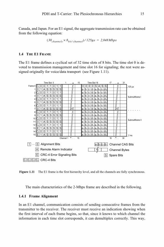
The E1 frame defines a cyclical set of 32 time slots of 8 bits. The time slot 0 is de-voted to transmission management and time slot 16 for signaling; the rest were as-signed originally for voice/data transport (see Figure 1.11).
The main characteristics of the 2-Mbps frame are described in the following.
1.4.1 Frame Alignment
In an E1 channel, communication consists of sending consecutive frames from the transmitter to the receiver. The receiver must receive an indication showing when the first interval of each frame begins, so that, since it knows to which channel the information in each time slot corresponds, it can demultiplex correctly. This way,
30channels 8bit channel⁄×( ) 125μs⁄ 2,048Mbps=
0 1C1 0 1 0 1 1 0 00 0 S A S SA S0 1 S S S S c 1 d 1a 1 b 1 a16 b16 c16 d16
c 2 d 2a 2 b 2 a17 b17 c17 d170 1C2 0 1 0 1 1A S0 1 S S S S c 3 d 3a 3 b 3 a18 b18 c18 d18
c 4 d 4a 4 b 4 a19 b19 c19 d190 1C3 0 1 0 1 1
Frame 0
1234
A S0 1 S S S S c 5 d 5a 5 b 5 a20 b20 c20 d20
c 6 d 6a 6 b 6 a21 b21 c21 d210 1C4 0 1 0 1 1A S0 1 S S S S c 7 d 7a 7 b 7 a22 b22 c22 d22
567
A S0 1 S S S S c 9 d 9a 9 b 9 a24 b24 c24 d24
c10 d10a10 b10 a25 b25 c25 d250 1C2 0 1 0 1 1A S0 1 S S S S c11 d11a11 b11 a26 b26 c26 d26
c12 d12a12 b12 a27 b27 c27 d270 1C3 0 1 0 1 1
9101112
A SE 1 S S S S c13 d13a13 b13 a28 b28 c28 d28
c14 d14a14 b14 a29 b29 c29 d290 1C4 0 1 0 1 1A SE 1 S S S S c15 d15a15 b15 a30 b30 c30 d30
131415
c 8 d 8a 8 b 8 a23 b23 c23 d230 1C1 0 1 0 1 18
Time Slot 0 1 15 Time Slot 16. . . 17 31. . .
125 μs
Submultiframe I
Submultiframe II
2 msChannel 1 15 16 30. . .. . .
Remote Alarm Indicator
Channel CAS BitsAlignment Bits
CRC-4 Bits
CRC-4 Error Signaling Bits
C1
A
SE
a17 b17 c17 d17
C2 C3 C4
Spare Bits
1 0...
Channel Bytes
Figure 1.11 The E1 frame is the first hierarchy level, and all the channels are fully synchronous.
Migration to Next Generation SDH16
the bytes received in each slot are assigned to the correct channel. A synchroniza-tion process is then established, and it is known as frame alignment.
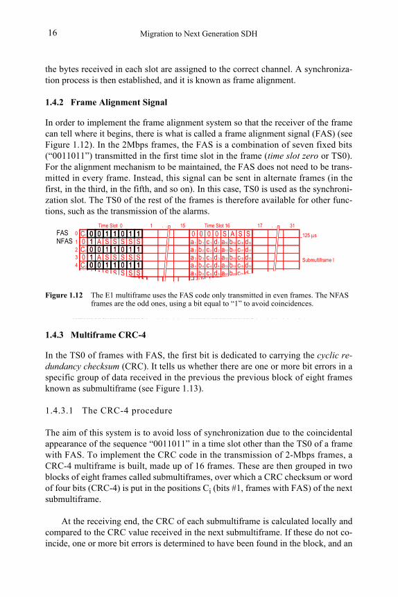
1.4.2 Frame Alignment Signal
In order to implement the frame alignment system so that the receiver of the frame can tell where it begins, there is what is called a frame alignment signal (FAS) (see Figure 1.12). In the 2Mbps frames, the FAS is a combination of seven fixed bits (“0011011”) transmitted in the first time slot in the frame (time slot zero or TS0). For the alignment mechanism to be maintained, the FAS does not need to be trans-mitted in every frame. Instead, this signal can be sent in alternate frames (in the first, in the third, in the fifth, and so on). In this case, TS0 is used as the synchroni-zation slot. The TS0 of the rest of the frames is therefore available for other func-tions, such as the transmission of the alarms.
1.4.3 Multiframe CRC-4
In the TS0 of frames with FAS, the first bit is dedicated to carrying the cyclic re-dundancy checksum (CRC). It tells us whether there are one or more bit errors in a specific group of data received in the previous the previous block of eight frames known as submultiframe (see Figure 1.13).
1.4.3.1 The CRC-4 procedure
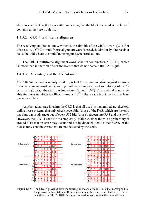
The aim of this system is to avoid loss of synchronization due to the coincidental appearance of the sequence “0011011” in a time slot other than the TS0 of a frame with FAS. To implement the CRC code in the transmission of 2-Mbps frames, a CRC-4 multiframe is built, made up of 16 frames. These are then grouped in two blocks of eight frames called submultiframes, over which a CRC checksum or word of four bits (CRC-4) is put in the positions Ci (bits #1, frames with FAS) of the next submultiframe.
At the receiving end, the CRC of each submultiframe is calculated locally and compared to the CRC value received in the next submultiframe. If these do not co-incide, one or more bit errors is determined to have been found in the block, and an
0 1C1 0 1 0 1 1 0 00 0 S A S SA S0 1 S S S S c 1 d 1a 1 b 1 a16 b16 c16 d16
c 2 d 2a 2 b 2 a17 b17 c17 d170 1C2 0 1 0 1 1A S0 1 S S S S c 3 d 3a 3 b 3 a18 b18 c18 d18
c 4 d 4a 4 b 4 a19 b19 c19 d190 1C3 0 1 0 1 1
0
1234
A S0 1 S S S S c 5 d 5a 5 b 5 a20 b20 c20 d20
c 6 d 6a 6 b 6 a21 b21 c21 d210 1C4 0 1 0 1 1A S0 1 S S S S c 7 d 7a 7 b 7 a22 b22 c22 d22
567
A S0 1 S S S S c 9 d 9a 9 b 9 a24 b24 c24 d24
c10 d10a10 b10 a25 b25 c25 d250 1C2 0 1 0 1 1A S0 1 S S S S c da b a b c d
91011
c 8 d 8a 8 b 8 a23 b23 c23 d230 1C1 0 1 0 1 18
Time Slot 0 1 15 Time Slot 16. . . 17 31. . .
125 μs
Submultiframe I
Sub-multiframe II
c 6 d 6a 6 b 6 a21 b21 c21 d21C4
A S0 S S S S c 7 d 7a 7 b 7 a22 b22 c22 d22
67
A S0 S S S S c 9 d 9a 9 b 9 a24 b24 c24 d24
c10 d10a10 b10 a25 b25 c25 d25C2
A S0 S S S S c da b a b c d
91011
c 8 d 8a 8 b 8 a23 b23 c23 d23C18
Submultiframe II
0 1 1 0 1 1
0 1 1 0 1 1
0 1 1 0 1 11
1
1
0
0
0
FAS NFAS
0 1 1 0 1 1
0 1 1 0 1 11
1
0
0
0 1 1 0 1 1
0 1 1 0 1 1
0 1 1 0 1 1
10
0
0
Figure 1.12 The E1 multiframe uses the FAS code only transmitted in even frames. The NFAS frames are the odd ones, using a bit equal to “1” to avoid coincidences.
PDH and T-Carrier: The Plesiochronous Hierarchies 17
alarm is sent back to the transmitter, indicating that the block received at the far end contains errors (see Table 1.2).
1.4.3.2 CRC-4 multiframe alignment
The receiving end has to know which is the first bit of the CRC-4 word (C1). For this reason, a CRC-4 multiframe alignment word is needed. Obviously, the receiver has to be told where the multiframe begins (synchronization).
The CRC-4 multiframe alignment word is the set combination “001011,” which is introduced in the first bits of the frames that do not contain the FAS signal.
1.4.3.3 Advantages of the CRC-4 method
The CRC-4 method is mainly used to protect the communication against a wrong frame alignment word, and also to provide a certain degree of monitoring of the bit error rate (BER), when this has low values (around 10-6). This method is not suit-able for cases in which the BER is around 10-3 (where each block contains at least one errored bit).
Another advantage in using the CRC is that all the bits transmitted are checked, unlike those systems that only check seven bits (those of the FAS, which are the only ones known in advance) out of every 512 bits (those between one FAS and the next). However, the CRC-4 code is not completely infallible, since there is a probability of around 1/16 that an error may occur and not be detected; that is, that 6.25% of the blocks may contain errors that are not detected by the code.
Figure 1.13 The CRC-4 provides error monitoring by means of four Ci bits that correspond to the previous submultiframe. If the receiver detects errors, it sets the E-bit to indi-cate the error. The “001011”sequence is used to synchronize the submultiframe.
0 10 1 0 1 1A S1 S S S S0 10 1 0 1 1A S1 S S S S0 10 1 0 1 1
1
3
A S1 S S S S0 10 1 0 1 1A S1 S S S S
5
7
A S1 S S S S0 10 1 0 1 1A S1 S S S S0 10 1 0 1 1
9
11
A S1 S S S S0 10 1 0 1 1A S1 S S S S
13
15
0 10 1 0 1 18
0
0
0
0
0
0
E
E
C1
0 C1
2
4
6
10
C2
C3
C4
C2
14 C4
12 C3
Submultiframe I
Submultiframe II
0 10 1 0 1 1A S1 S S S S0 10 1 0 1 1A S1 S S S S0 10 1 0 1 1
0
A S1 S S S S0 10 1 0 1 1A S1 S S S S
A S1 S S S S0 10 1 0 1 1A S1 S S S S0 10 1 0 1 1
10
12
A S1 S S S S0 10 1 0 1 1A S1 S S S S
14
0 10 1 0 1 1
C1
C2
C3
2
4
C46
C2
C3
C4
C18
01
11
13
15
03
1
0
5
7
1
1
9
E
E
Submultiframe I
Submultiframe II
Migration to Next Generation SDH18
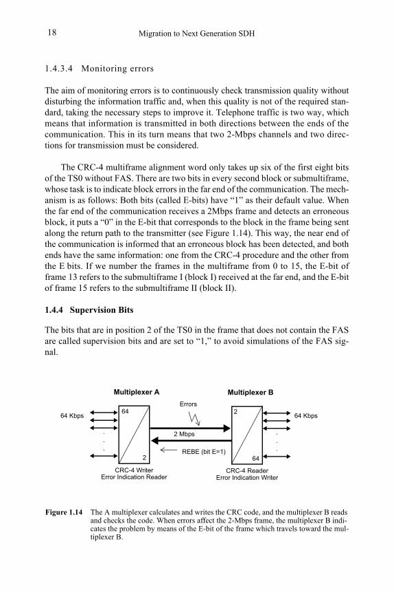
1.4.3.4 Monitoring errors
The aim of monitoring errors is to continuously check transmission quality without disturbing the information traffic and, when this quality is not of the required stan-dard, taking the necessary steps to improve it. Telephone traffic is two way, which means that information is transmitted in both directions between the ends of the communication. This in its turn means that two 2-Mbps channels and two direc-tions for transmission must be considered.
The CRC-4 multiframe alignment word only takes up six of the first eight bits of the TS0 without FAS. There are two bits in every second block or submultiframe, whose task is to indicate block errors in the far end of the communication. The mech-anism is as follows: Both bits (called E-bits) have “1” as their default value. When the far end of the communication receives a 2Mbps frame and detects an erroneous block, it puts a “0” in the E-bit that corresponds to the block in the frame being sent along the return path to the transmitter (see Figure 1.14). This way, the near end of the communication is informed that an erroneous block has been detected, and both ends have the same information: one from the CRC-4 procedure and the other from the E bits. If we number the frames in the multiframe from 0 to 15, the E-bit of frame 13 refers to the submultiframe I (block I) received at the far end, and the E-bit of frame 15 refers to the submultiframe II (block II).
1.4.4 Supervision Bits
The bits that are in position 2 of the TS0 in the frame that does not contain the FAS are called supervision bits and are set to “1,” to avoid simulations of the FAS sig-nal.
Figure 1.14 The A multiplexer calculates and writes the CRC code, and the multiplexer B reads and checks the code. When errors affect the 2-Mbps frame, the multiplexer B indi-cates the problem by means of the E-bit of the frame which travels toward the mul-tiplexer B.
REBE (bit E=1)
CRC-4 Writer CRC-4 Reader
2
2 Errors
Multiplexer A Multiplexer B
Error Indication Reader Error Indication Writer
.
.
.
.
.
.
64
64
2 Mbps
64 Kbps 64 Kbps
PDH and T-Carrier: The Plesiochronous Hierarchies 19
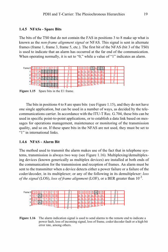
1.4.5 NFASs - Spare Bits
The bits of the TS0 that do not contain the FAS in positions 3 to 8 make up what is known as the non-frame alignment signal or NFAS. This signal is sent in alternate frames (frame 1, frame 3, frame 5, etc.). The first bit of the NFAS (bit 3 of the TS0) is used to indicate that an alarm has occurred at the far end of the communication. When operating normally, it is set to “0,” while a value of “1” indicates an alarm.
The bits in positions 4 to 8 are spare bits (see Figure 1.15), and they do not have one single application, but can be used in a number of ways, as decided by the tele-communications carrier. In accordance with the ITU-T Rec. G.704, these bits can be used in specific point-to-point applications, or to establish a data link based on mes-sages for operations management, maintenance or monitoring of the transmission quality, and so on. If these spare bits in the NFAS are not used, they must be set to “1” in international links.
1.4.6 NFAS - Alarm Bit
The method used to transmit the alarm makes use of the fact that in telephone sys-tems, transmission is always two way (see Figure 1.16). Multiplexing/demultiplex-ing devices (known generically as multiplex devices) are installed at both ends of the communication for the transmission and reception of frames. An alarm must be sent to the transmitter when a device detects either a power failure or a failure of the coder/decoder, in its multiplexer; or any of the following in its demultiplexer: loss of the signal (LOS), loss of frame alignment (LOF), or a BER greater than 10-3.
0C3 04 1 1 0 1 1
0C2 02 1 1 0 1 1
0C1 0 0 00 00 1 c 1 d 1a 1 b 1 a16 b16 c16 d16
c 2 d 2a 2 b 2 a17 b17 c17 d17
0 1 c 3 d 3a 3 b 3 a18 b18 c18 d18
c 4 d 4a 4 b 4 a19 b19 c19 d19
Frame 0
1
3
0 1 c 5 d 5a 5 b 5 a20 b20 c20 d20
c 6 d 6a 6 b 6 a21 b21 c21 d210 1C4 0 1 0 1 156
A
A
A
AS S S1 1 0 1 1S S S S S
S S S S S
S S S S S
Figure 1.15 Spare bits in the E1 frame.
0 1C1 0 1 0 1 1 0 00 0 S S SS0 1 S S S S c 1 d 1a 1 b 1 a16 b16 c16 d16
c 2 d 2a 2 b 2 a17 b17 c17 d170 1C2 0 1 0 1 1S0 1 S S S S c 3 d 3a 3 b 3 a18 b18 c18 d18
c 4 d 4a 4 b 4 a19 b19 c19 d190 1C3 0 1 0 1 1
Frame 0
1234
S0 1 S S S S c 5 d 5a 5 b 5 a20 b20 c20 d20
c 6 d 6a 6 b 6 a21 b21 c21 d210 1C4 0 1 0 1 156
Submultiframe II
A
A
A
A
Figure 1.16 The alarm indication signal is used to send alarms to the remote end to indicate a power fault, loss of incoming signal, loss of frame, coder/decoder fault or a high bit error rate, among others.
Migration to Next Generation SDH20
The remote alarm indication (RAI) is sent in the NFAS of the return frames, with bit 3 being set to “1.” The transmitter then considers how serious the alarm is, and goes on generating a series of operations, depending on the type of alarm con-dition detected (see Table 1.2).
1.4.7 Signaling Channel
As well as transmitting information generated by the users of a telephone network, it is also necessary to transmit signaling information. Signaling refers to the proto-cols that must be established between exchanges so that the users can exchange in-formation between them.
There are signals that indicate when a subscriber has picked up the telephone, when he or she can start to dial a number, and when another subscriber calls, as well as signals that let the communication link be maintained, and so on.
In the E1 PCM system, signaling information can be transmitted by two differ-ent methods: the common channel signaling (CCS) method and the channel associ-ated signaling (CAS) method. In both cases, the time slot TS16 of the basic 2-Mbps frame is used to transmit the signaling information (see Figure 1.17).
For CCS signaling, messages of several bytes are transmitted through the 64-Kbps channel provided by the TS16 of the frame, with these messages providing the signaling for all the channels in the frame. Each message contains information that determines the channel that is signaling. The signaling circuits access the 64-Kbps channel of the TS16, and they are also common to all the channels signaled. There are different CCS systems that constitute complex protocols. In the following section and by way of example, channel associated signaling will be looked at in de-tail. CAS is defined in the ITU-T Rec. G.704, which defines the structure of the E1 frame.
In CAS signaling, a signaling channel is associated with each information chan-nel (there is no common signaling channel), meaning that the signaling circuits are personalized for each channel.
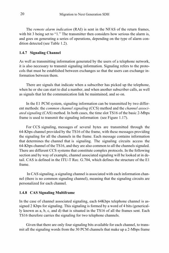
1.4.8 CAS Signaling Multiframe
In the case of channel associated signaling, each 64Kbps telephone channel is as-signed 2 Kbps for signaling. This signaling is formed by a word of 4 bits (generical-ly known as a, b, c, and d) that is situated in the TS16 of all the frames sent. Each TS16 therefore carries the signaling for two telephone channels.
Given that there are only four signaling bits available for each channel, to trans-mit all the signaling words from the 30 PCM channels that make up a 2-Mbps frame
PDH and T-Carrier: The Plesiochronous Hierarchies 21
(120 bits), it is necessary to wait until the TS16 of 15 consecutive frames have been received. The grouping of frames defines a CAS signaling multiframe, which con-sists of a set of the TS16 of 16 consecutive E1 frames.
1.4.8.1 CAS multiframe alignment signal
In order to synchronize the CAS multiframe, that is to identify where it begins, a multiframe alignment signal (MFAS) is defined, made up of the sequence of bits “0000” located in the first four bits of the TS16 of the first frame of the CAS multi-frame.
1.4.8.2 CAS non-multiframe alignment signal
The remaining four bits of the interval are divided between one alarm bit and three spare bits, making up the non-multiframe alignment signal (NMFAS). In short, the signaling information for the 30 channels is transmitted in 2 ms, which is fast enough if we consider that the shortest signaling pulse (the one that corresponds to dialing the number) lasts for 100 ms.
The alarm bit in the NMFAS is dealt with in a similar way to the NFAS. In this case, the alarms are transmitted between multiplex signaling devices connected to the 64-Kbps circuits that correspond to signaling (TS16). The alarm is sent when the CAS multiplexer detects:
• A power failure;
• Loss of incoming signaling;
• Loss of CAS multiframe alignment.
An indication must be sent to the multiplex signaling device at the far end (see Ta-ble 1.2), setting bit 6 of the TS16 in the return frame 0 to “1.” Additionally, the val-ue “1” is applied to all the signaling channels (see Figure 1.21).
0 1C1 0 1 0 1 1 0 00 0 S S SS0 1 S S S S c 1 d 1a 1 b 1 a16 b16 c16 d16
c 2 d 2a 2 b 2 a17 b17 c17 d170 1C2 0 1 0 1 1S0 1 S S S S c 3 d 3a 3 b 3 a18 b18 c18 d18
c 4 d 4a 4 b 4 a19 b19 c19 d190 1C3 0 1 0 1 1
Frame 0
1234
S0 1 S S S S c 5 d 5a 5 b 5 a20 b20 c20 d20
c 6 d 6a 6 b 6 a21 b21 c21 d210 1C4 0 1 0 1 156
Submultiframe II
A
A
A
ATime Slot 0 1 15 Time Slot 16. . . 17 31. . .
Figure 1.17 When the CAS method is used, each of the channels has an associated 2-Kbps channel (ai bi ci di) in the time slot 16. This multiframe also has an alignment signal “0000”; spare and alarm bit to be used specifically by the signaling multiframe.
Migration to Next Generation SDH22
Example: A remote multiplexer is considered to have lost multiframe alignment when it receives two consecutive MFAS words with error, that is, with a value other than “0000.” In this case, bit 6 of the TI16 of the frame 0 that this multiplexer trans-mits to the near-end multiplexer is set to “1.” When it receives this indication of loss of multiframe alignment at the far end, the near end multiplexer sends a signal made up entirely of bits at “1,” known as AIS64 (alarm indication signal - 64 Kbps) in the TS16 (64-Kbps channel).
1.5 THE PLESIOCHRONOUS DIGITAL HIERARCHY
Based on the E1 signal, the ITU-T defined a hierarchy of plesiochronous signals that enables signals to be transported at rates of up to 140 Mbps (see Figure 1.18). This section describes the characteristics of this hierarchy and the mechanism for dealing with fluctuations in respect to the nominal values of these rates, which are produced as a consequence of the tolerances of the system.
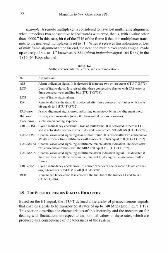
Table 1.22-Mbps events: Alarms, errors, and event indications.
ID Explanation
AIS Alarm indication signal. It is detected if there are two or less zeros (ITU-T G.775).
LOF Loss of frame alarm. It is raised after three consecutive frames with FAS error or three consecutive signalling bits (ITU-T G.706).
LOS Loss of frame signal alarm.
RAI Remote alarm indication. It is detected after three consecutive frames with the A bit equals to 1 (ITU-T G.732).
FAS error Frame alignment signal error, indicating an incorrect bit in the alignment word.
Bit error Bit sequence mismatch (when the transmitted pattern is known).
Code error Violation on coding sequence.
CRC-LOM Cyclic redundancy checksum - loss of multiframe. It is activated if there is LOF and deactivated after one correct FAS and two correct CRC-MFAS (ITU-T G.706).
CAS-LOM Channel associated signaling-loss of multiframe. It is raised after two consecutive MFAS errors or two multiframes with time-slot 16 bits equal to 0 (ITU-T G.732).
CAS-MRAI Channel associated signaling-multiframe remote alarm indication. Detected after two consecutive frames with the MRAI bit equal to 1 (ITU-T G.732).
CAS-MAIS Channel associated signaling-multiframe alarm indication signal. It is detected if there are less than three zeros in the time slot 16 during two consecutive multi-frames.
CRC error Cyclic redundancy check error. It is raised whenever one or more bits are errone-ous, whenever CRC-LOM is off (ITU-T G.706).
REBE Remote end block error. It is erased if the first bit of the frames 14 and 16 is 0 (ITU-T G.706).
PDH and T-Carrier: The Plesiochronous Hierarchies 23
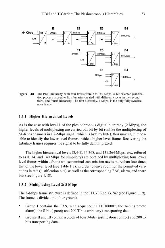
1.5.1 Higher Hierarchical Levels
As is the case with level 1 of the plesiochronous digital hierarchy (2 Mbps), the higher levels of multiplexing are carried out bit by bit (unlike the multiplexing of 64-Kbps channels in a 2-Mbps signal, which is byte by byte), thus making it impos-sible to identify the lower level frames inside a higher level frame. Recovering the tributary frames requires the signal to be fully demultiplexed.
The higher hierarchical levels (8,448, 34,368, and 139,264 Mbps, etc.; referred to as 8, 34, and 140 Mbps for simplicity) are obtained by multiplexing four lower level frames within a frame whose nominal transmission rate is more than four times that of the lower level (see Table 1.3), in order to leave room for the permitted vari-ations in rate (justification bits), as well as the corresponding FAS, alarm, and spare bits (see Figure 1.18).
1.5.2 Multiplexing Level 2: 8 Mbps
The 8-Mbps frame structure is defined in the ITU-T Rec. G.742 (see Figure 1.19). The frame is divided into four groups:
• Group I contains the FAS, with sequence “1111010000”; the A-bit (remote alarm); the S-bit (spare); and 200 T-bits (tributary) transporting data.
• Groups II and III contain a block of four J-bits (justification control) and 208 T-bits transporting data.
Figure 1.18 The PDH hierarchy, with four levels from 2 to 140 Mbps. A bit-oriented justifica-tion process is used to fit tributaries created with different clocks in the second, third, and fourth hierarchy. The first hierarchy, 2 Mbps, is the only fully synchro-nous frame.
.64
2
34
140
8
34
x4 x4x30
34Mbps
2
8
x4
34Mbps8Mbps2Mbps64Kbps .64
2
2
140
8
34
x4 x4x30
2Mbps
x16
140Mbps2
140
2Mbps
x64
34
140
140Mbps
140Mbps
E1 E2 E3 E4
E1 E3
E1
E4
E4
Migration to Next Generation SDH24
• Group IV contains a block of four J-bits, a block of R-bits (justification oppor-tunity), one per tributary, and 204 T-bits. To check whether R-bits have been used, the J-bits are analyzed in each of the groups II, III, and IV (there are three per tributary). Ideally the R-bit does not carry useful information on 42.4% of the occasions. In other words, this percentage is the probability of justification or the insertion of stuffing bits.
1.5.3 Multiplexing Level 3: 34 Mbps
The structure of this frame is described in the ITU-T Rec. G.751 (see Figure 1.19). As in the previous case, the frame is divided into four groups:
• Group I contains the FAS, with sequence “1111010000”; the A-bit (remote alarm); the S-bit (spare); and 372 T-bits (tributary) transporting data.
• Groups II and III contain a block of four J-bits (justification control) and 380 T-bits transporting data.
• Group IV contains a block of four J-bits, a block of R-bits (justification oppor-tunity) one per tributary, and 376 T-bits. To check whether R-bits have been used, the J-bits are analyzed in each of the groups II, III, and IV (there are three per tributary). Ideally the R-bit does not carry useful information on 43.6% of the occasions.
1.5.4 Multiplexing Level 4: 140 Mbps
The structure of this frame is described in the ITU-T Rec. G.751 (see Figure 1.19). In this case, the frame is divided into six groups:
• Group I contains the FAS, with sequence “111110100000;” the A-bit (remote alarm); the S-bit (spare); and 472 T-bits (tributary) transporting data.
• Groups II, III, IV, and V contain a block of four J-bits (justification control) and 484 T-bits transporting data.
• Group VI contains a block of four J-bits, a block of R-bits (justification oppor-tunity), one per tributary, and 376 T-bits. To check whether R-bits have been used, the J-bits are analyzed in each of the groups II, III, IV, V, and VI (there are five per tributary). Ideally the R-bit does not carry useful information on 41.9% of the occasions.
1.5.5 Service Bits in Higher Level Frames
In any of the groups containing the FAS in the 8-, 34-, and 140-Mbps frames, alarm bits and spare bits are also to be found. These are known as service bits. The A-bits (alarm) carry an alarm indication to the remote multiplexing device, when certain

PDH and T-Carrier: The Plesiochronous Hierarchies 25
J1 J2 J3 J4 R1 R2 R3 R4 T1 T2 T3 T4
29282441
T1 T2 T3 T4
11 1 1 0 1 0 00 0 A S T1 T2 T3 T1 T2 T3 T4
384134 Mbps
11
Remote Alarm Indicator Justification Opportunity Bits
Frame Alignment Signal (Fas)
AS Spare Bits
1 0...
Justification Control BitsT1 T2 T3 T4 Tributary Bits
Figure 1.19 The PDH higher hierarchies. A bit-oriented justification process is used to fit tribu-taries created with clock impairments.
T4
1 11 1 1 0 1 0 00 0 0 A S S S T1 T2 T3 T4T1 T2 T3 T4
17 4881140 Mbps
13
J1 J2 J3 J4 T1 T2 T3 T4 T1 T2 T3 T4
976489
J1 J2 J3 J4 T1 T2 T3 T4 T1 T2 T3 T4
1464977
J1 J2 J3 J4 T1 T2 T3 T4 T1 T2 T3 T4
19521465
J1 J2 J3 J4 T1 T2 T3 T4 T1 T2 T3 T4
24401953
T1 T2 T3 T4
T1 T2 T3 T4
T1 T2 T3 T4
T1 T2 T3 T4
J1 J2 J3 J4 T1 T2 T3 T4 T1 T2 T3 T4T1 T2 T3 T4
385 768
J1 J2 J3 J4 T1 T2 T3 T4 T1 T2 T3 T4T1 T2 T3 T4
769 1152
J1 J2 J3 J4 R1 R2 R3 R4 T1 T2 T3 T4T1 T2 T3 T4
1153 1536
J1 J2 J3 J4
11 1 1 0 1 0 00 0 A S T1 T2 T3 T1 T2 T3 T4
21218 Mbps
11
T4
J1 J2 J3 J4 T1 T2 T3 T4 T1 T2 T3 T4T1 T2 T3 T4
213 424
J1 J2 J3 J4 T1 T2 T3 T4 T1 T2 T3 T4T1 T2 T3 T4
425 636
J1 J2 J3 J4 R1 R2 R3 R4 T1 T2 T3 T4T1 T2 T3 T4
637 848
: Group I
: Group II
: Group III
: Group IV
: Group V
: Group VI
R1 R2 R3 R4
44,7 μs
21,02 μs
42,4 μs
: Group I
: Group II
: Group III
: Group IV
: Group I
: Group II
: Group III
: Group IV
Bits
per
trib
utar
y(Σ
Ti+
Ri)
: 205
+1
bits
Bits
per
trib
uta
ry(Σ
Ti+
Ri):
377
+1
bits
Bits
per
trib
utar
y(Σ
Ti+
Ri)
: 722
+1
bits
Migration to Next Generation SDH26
breakdown conditions are detected in the near-end device. The spare bits are de-signed for national use, and must be set to “1” in digital paths that cross internation-al boundaries.
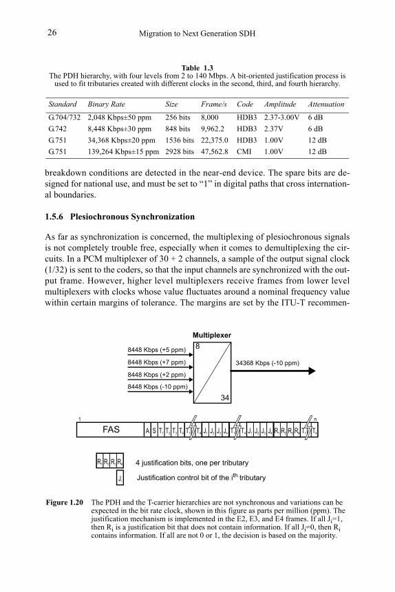
1.5.6 Plesiochronous Synchronization
As far as synchronization is concerned, the multiplexing of plesiochronous signals is not completely trouble free, especially when it comes to demultiplexing the cir-cuits. In a PCM multiplexer of 30 + 2 channels, a sample of the output signal clock (1/32) is sent to the coders, so that the input channels are synchronized with the out-put frame. However, higher level multiplexers receive frames from lower level multiplexers with clocks whose value fluctuates around a nominal frequency value within certain margins of tolerance. The margins are set by the ITU-T recommen-
Table 1.3The PDH hierarchy, with four levels from 2 to 140 Mbps. A bit-oriented justification process is
used to fit tributaries created with different clocks in the second, third, and fourth hierarchy.
Standard Binary Rate Size Frame/s Code Amplitude Attenuation
G.704/732 2,048 Kbps±50 ppm 256 bits 8,000 HDB3 2.37-3.00V 6 dB
G.742 8,448 Kbps±30 ppm 848 bits 9,962.2 HDB3 2.37V 6 dB
G.751 34,368 Kbps±20 ppm 1536 bits 22,375.0 HDB3 1.00V 12 dB
G.751 139,264 Kbps±15 ppm 2928 bits 47,562.8 CMI 1.00V 12 dB
Figure 1.20 The PDH and the T-carrier hierarchies are not synchronous and variations can be expected in the bit rate clock, shown in this figure as parts per million (ppm). The justification mechanism is implemented in the E2, E3, and E4 frames. If all Ji=1, then Ri is a justification bit that does not contain information. If all Ji=0, then Ri contains information. If all are not 0 or 1, the decision is based on the majority.
Ji Justification control bit of the ith tributary
R1 R2 R4R3 4 justification bits, one per tributary
8
34
8448 Kbps (+5 ppm)
8448 Kbps (+7 ppm)
8448 Kbps (+2 ppm)
8448 Kbps (-10 ppm)
34368 Kbps (-10 ppm)
A S T1 T2 T3 J1 J2 J3 J4T4 J1 J2 J3 J4 R1 R2 R4
1
T4T1T4T1 T4T1R3FASn
Multiplexer
PDH and T-Carrier: The Plesiochronous Hierarchies 27
dations for each hierarchical level. The signals thus formed are almost synchro-nous, except for differences within the permitted margins of tolerance, and for this reason they are called plesiochronous (see Figure 1.20).
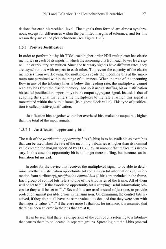
1.5.7 Positive Justification
In order to perform bit-by-bit TDM, each higher-order PDH multiplexer has elastic memories in each of its inputs in which the incoming bits from each lower level sig-nal line or tributary are written. Since the tributary signals have different rates, they are asynchronous with respect to each other. To prevent the capacity of the elastic memories from overflowing, the multiplexer reads the incoming bits at the maxi-mum rate permitted within the range of tolerances. When the rate of the incoming flow in any of the tributary lines is below this reading rate, the multiplexer cannot read any bits from the elastic memory, and so it uses a stuffing bit or justification bit (called justification opportunity) in the output aggregate signal. Its task is that of adapting the signal that enters the multiplexer to the rate at which this signal is transmitted within the output frame (its highest clock value). This type of justifica-tion is called positive justification.
Justification bits, together with other overhead bits, make the output rate higher than the total of the input signals.
1.5.7.1 Justification opportunity bits
The task of the justification opportunity bits (R-bits) is to be available as extra bits that can be used when the rate of the incoming tributaries is higher than its nominal value (within the margin specified by ITU-T) by an amount that makes this neces-sary. In this case, the opportunity bit is no longer mere stuffing, but becomes an in-formation bit instead.
In order for the device that receives the multiplexed signal to be able to deter-mine whether a justification opportunity bit contains useful information (i.e., infor-mation from a tributary), justification control bits (J-bits) are included in the frame. Each group of control bits refers to one of the tributaries of the frame. All of them will be set to “0” if the associated opportunity bit is carrying useful information; oth-erwise they will be set to “1.” Several bits are used instead of just one, to provide protection against possible errors in transmission. On examining the control bits re-ceived, if they do not all have the same value, it is decided that they were sent with the majority value (a “1” if there are more 1s than 0s, for instance; it is assumed that there has been an error in the bits that are at 0).
It can be seen that there is a dispersion of the control bits referring to a tributary that causes them to be located in separate groups. Spreading out the J-bits (control
Migration to Next Generation SDH28
bits), reduces the probability of errors occurring in them, and a wrong decision being made as to whether or not they have been used as a useful data bit. If the wrong de-cision is made, there is not only an error in the output data, but also a slip of one bit; that is, the loss or repetition of one bit of information.
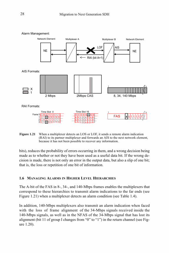
1.6 MANAGING ALARMS IN HIGHER LEVEL HIERARCHIES
The A-bit of the FAS in 8-, 34-, and 140-Mbps frames enables the multiplexers that correspond to these hierarchies to transmit alarm indications to the far ends (see Figure 1.21) when a multiplexer detects an alarm condition (see Table 1.4).
In addition, 140-Mbps multiplexers also transmit an alarm indication when faced with the loss of frame alignment of the 34-Mbps signals received inside the 140-Mbps signals, as well as in the NFAS of the 34-Mbps signal that has lost its alignment (bit 11 of group I changes from “0” to “1”) in the return channel (see Fig-ure 1.20).
0 1C1 0 1 0 1 1 0 00 0 S S SS0 1 S S S S c 1 d 1a 1 b 1 a16 b16 c16 d16
c 2 d 2a 2 b 2 a17 b17 c17 d170 1C2 0 1 0 1 1S0 1 S S S S c 3 d 3a 3 b 3 a18 b18 c18 d18
Frame 0123
A
A
ATime Slot 0 Time Slot 16
A S T1 T2 T3 T4
1
T1FASn
2 Mbps 8, 34, 140 Mbps 2Mbps CAS
RAI (bit A=1)
LOF AIS
: X: 1
Figure 1.21 When a multiplexer detects an LOS or LOF, it sends a remote alarm indication (RAI) to its partner multiplexer and forwards an AIS to the next network element, because it has not been possible to recover any information.
Multiplexer B Network ElementMultiplexer A
AIS Formats:
Alarm Management:
1 n
RAI Formats:
NE
Network Element
NE
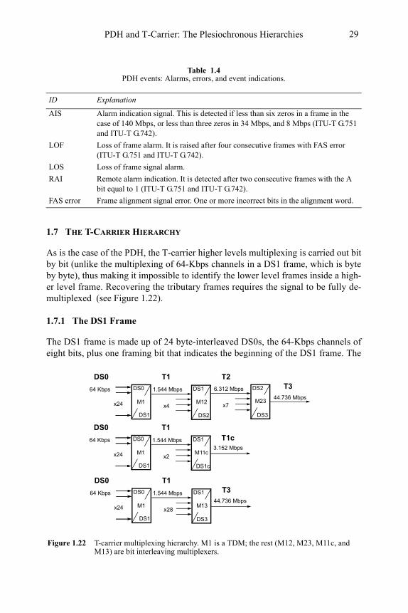
PDH and T-Carrier: The Plesiochronous Hierarchies 29
1.7 THE T-CARRIER HIERARCHY
As is the case of the PDH, the T-carrier higher levels multiplexing is carried out bit by bit (unlike the multiplexing of 64-Kbps channels in a DS1 frame, which is byte by byte), thus making it impossible to identify the lower level frames inside a high-er level frame. Recovering the tributary frames requires the signal to be fully de-multiplexed (see Figure 1.22).
1.7.1 The DS1 Frame
The DS1 frame is made up of 24 byte-interleaved DS0s, the 64-Kbps channels of eight bits, plus one framing bit that indicates the beginning of the DS1 frame. The
Table 1.4PDH events: Alarms, errors, and event indications.
ID Explanation
AIS Alarm indication signal. This is detected if less than six zeros in a frame in the case of 140 Mbps, or less than three zeros in 34 Mbps, and 8 Mbps (ITU-T G.751 and ITU-T G.742).
LOF Loss of frame alarm. It is raised after four consecutive frames with FAS error (ITU-T G.751 and ITU-T G.742).
LOS Loss of frame signal alarm.
RAI Remote alarm indication. It is detected after two consecutive frames with the A bit equal to 1 (ITU-T G.751 and ITU-T G.742).
FAS error Frame alignment signal error. One or more incorrect bits in the alignment word.
Figure 1.22 T-carrier multiplexing hierarchy. M1 is a TDM; the rest (M12, M23, M11c, and M13) are bit interleaving multiplexers.
DS2
x7x24
DS1
x4
44.736 Mbps
6.312 Mbps1.544 Mbps64 Kbps DS0
DS0 T1 T2T3
DS1 DS3
M1 M12 M23
x24
DS1
x2
64 Kbps DS0
DS0 T1T1c
DS1
M1 M11c
DS2
DS1c
3.152 Mbps1.544 Mbps
x24
DS1
x28
64 Kbps DS0
DS0 T1T3
DS1
M1 M13
DS3
44.736 Mbps1.544 Mbps
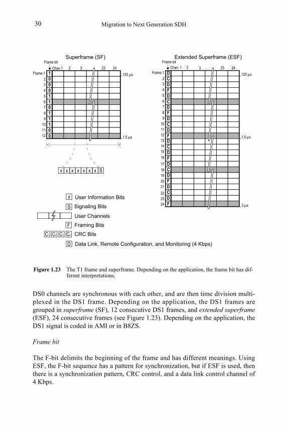
Migration to Next Generation SDH30
DS0 channels are synchronous with each other, and are then time division multi-plexed in the DS1 frame. Depending on the application, the DS1 frames are grouped in superframe (SF), 12 consecutive DS1 frames, and extended superframe(ESF), 24 consecutive frames (see Figure 1.23). Depending on the application, the DS1 signal is coded in AMI or in B8ZS.
Frame bit
The F-bit delimits the beginning of the frame and has different meanings. Using ESF, the F-bit sequence has a pattern for synchronization, but if ESF is used, then there is a synchronization pattern, CRC control, and a data link control channel of 4 Kbps.
DCDFDCDFDCDF
1
x xx x x x x S
125 μs
Superframe (SF)
Data Link, Remote Configuration, and Monitoring (4 Kbps)
CRC Bits
Framing Bits
C1
S
F
D
C2 C3 C4
x
Figure 1.23 The T1 frame and superframe. Depending on the application, the frame bit has dif-ferent interpretations.
00011011100
234
567
9101112
8
Frame 1. . . 2423
Frame bit
1.5 μs
D 125 μsCDFDCDFDCDF
24
1.5 μs
3 μs
Extended Superframe (ESF)
Signaling Bits
User Information Bits
User Channels
Frame bit
234
567
9101112
8
Frame 1
131415
16
17
192021
18
222324
Chan. 1 2 Chan.1 2 3 . . . 233
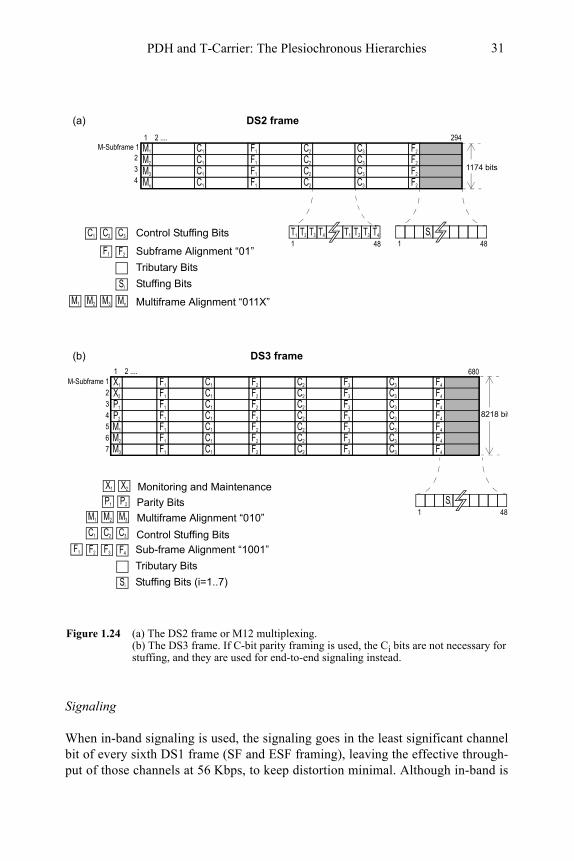
PDH and T-Carrier: The Plesiochronous Hierarchies 31
Signaling
When in-band signaling is used, the signaling goes in the least significant channel bit of every sixth DS1 frame (SF and ESF framing), leaving the effective through-put of those channels at 56 Kbps, to keep distortion minimal. Although in-band is
Figure 1.24 (a) The DS2 frame or M12 multiplexing. (b) The DS3 frame. If C-bit parity framing is used, the Ci bits are not necessary for stuffing, and they are used for end-to-end signaling instead.
T1 T2 T3 T4T1 T2 T3 T4
1 48
M1M-Subframe 1 C1 F1 C2 C3 F2
M2 C1 F1 C2 C3 F2
M3 C1 F1 C2 C3 F2
Mx C1 F1 C2 C3 F2
Si
1 48C3
F2
Si
1174 bits
Control Stuffing Bits
Subframe Alignment “01”
Tributary Bits
Stuffing Bits
1 2 .... 294
M1 M2 M3 Mx Multiframe Alignment “011X”
F1
C2C1
X1 M-Subframe 1
Si
1 48
C3
F4
Si
Control Stuffing Bits
Sub-frame Alignment “1001”
Tributary Bits
Stuffing Bits (i=1..7)
1 2 ....
M1 M2 M3 Multiframe Alignment “010”
F3
C2C1
F1 C1 F2 C2 F3 C3 F4
680
X2 F1 C1 F2 C2 F3 C3 F4
P1 F1 C1 F2 C2 F3 C3 F4
P2 F1 C1 F2 C2 F3 C3 F4
M1 F1 C1 F2 C2 F3 C3 F4
M2 F1 C1 F2 C2 F3 C3 F4
M3 F1 C1 F2 C2 F3 C3 F4
234567
F2F1
P1 P2 Parity Bits
X1 X2 Monitoring and Maintenance
DS3 frame
DS2 frame
8218 bit
234
(b)
(a)
Migration to Next Generation SDH32
still in use, signaling (call setup, teardown, routing, and status) is generally carried out of band over a separate network using a protocol called signaling system 7(SS7).
1.7.2 The DS2 Frame
As long as the DS1 frames are asynchronous from each other, each DS1 line is treated as a bit stream rather than individual frames, and the DS2 signal is formed by bit interleaving of four DS1 signals. Stuffing bits are added to the DS2 to com-pensate for the slightly different rates. Framing, signaling, alarm, frame alignment, and parity are also added to the frame (see Figure 1.24).
1.7.3 The DS3 Frame
A DS3 frame is formed by bit-interleaving 28 DS1 frames or seven DS2 frames. There are two framing formats, called M13 or C-bit parity (see Figure 1.24), de-scribed in the following:
1. M-13, multiplexing DS1 to DS3, is done in two steps: (a) the first four DS1 frames form a DS2 frame using M12 multiplexing; (b) the second seven DS2 frames form a DS3 frame using M23 multiplexing. M13 multiplexing uses bit stuffing to bring each asynchronous DS1/DS2 line up to a common data rate for transmission.
2. C-12, multiplexing DS1 to DS3, is done in one step: The stuffing control bits (C-bits) at the M23 multiplexing level are not required and can be used for a maintenance link between the end points, applications like far-end alarm and control (FEAC) and far-end block error (FEBE).
If C-bit parity framing is used, the Ci-bits in the DS3 frame take on signaling defi-nitions as described in the ANSI T1.107 (see Table 1.5).
Table 1.5C-bit parity: alarm and status signal codes.
Code Event Type Explanation
00110010 11111111
00011110 11111111
00000000 11111111
00001010 11111111
00011100 11111111
00101010 11111111
00111100 11111111
00000000 11111111
00101100 11111111
DS3 equipment failure Service affecting (SA), requires quick attention
DS3 equipment failure Non-service affecting (NSA)
DS1 equipment failure Service affecting (SA), requires quick attention
DS1 equipment failure Non-service affecting (NSA)
DS3 LOS Loss of signal
Multiple DS1 LOS Multiple loss of frame in the DS1 tributaries
Single DS1 LOS Alarm indication signal received from a DS1
DS3 OOF Out of frame in the DS3 signal
DS2 AIS Alarm indication signal received from a DS2
PDH and T-Carrier: The Plesiochronous Hierarchies 33
Selected Bibliography
• William Stallings, Data and Computer Communications, Prentice Hall, 1997.
• Fred Halsall, Data Communications, Computer Networks and OSI, Addison-Wesley, 1998.
• Llorens Cerdá, Transmissió de Dades, Universitat Oberta de Catalunya, 1999.
• Stanatios V. Kartalopoulos, Understanding SDH/SONET and ATM, IEEE Press, 1999.
• ANSI T1.403, DS1 metallic interface.
• ANSI T1.107, Digital hierarchy formats.
• ITU-T Rec. G.703 (10/98), Physical/electrical characteristics of hierarchical digital interfaces.
• ITU-T Rec. G.704 (10/98), Synchronous frame structures used at 1,544, 6,312, 2,048, 8,448 and 44,736 Kbit/s hierarchical levels.
• ITU-T Rec. G.742 (11/88), Second order digital multiplex equipment operating at 8,448 Kbit/s and using positive justification.
• ITU-T Rec. G.751 (11/88), Digital multiplex equipment operating at the third order bit rate of 34,368 Kbit/s and the fourth order bit rate of 139,264 Kbit/s and using positive justification.
• José M. Caballero, Redes de Banda Ancha, Marcombo, 1997.
• José M. Caballero and Andreu Guimera, Jerarquías Digitales de Multiplexión, PDH y SDH, Sincron-ización de Redes, L&M Data Communications, 2001.

Migration to Next Generation SDH34
35
Chapter 2
Classic SDH/SONET
Synchronous digital hierarchy (SDH) is an ITU-T universal standard that defines a common and reliable architecture for transporting telecommunications services on a worldwide scale. Synchronous optical network (SONET) is today a subset of SDH, promoted by American National Standards Institute (ANSI) and used in the U.S., Canada, Taiwan, and Korea.
From now on we will use the acronym SDH to refer to the generic ITU-T stan-dard that includes also SONET.
2.1 THE EMERGENCE OF SDH/SONET NETWORKS
During the 1980s, progress in optical technologies and microprocessors offered new challenges to telecommunications in terms of bandwidth and data processing. At that time, plesiochronous hierarchies (T-carrier and PDH) dominated transport systems, but a series of limitations and the necessity to introduce new transmission technologies moved to develop a new architecture.
Antitrust legislation was the final factor that hastened the development of SON-ET. It was applied to the telecommunications business and forced the giant, Bell, to be split up into small companies, the regional Bell operating companies (RBOCs). SONET, developed at Bellcore labs in 1984, grew out of the need to inter-connect RBOCs using standardized optical interfaces. Telecom liberalization was confirmed around the world during the ‘90s, and this has inevitably led to global competition and interoperation. In 1988, the Comité Consultatif International Télégraphique Et Téléphonique CCITT (now ITU) proposed creating broadband-ISDN (B-ISDN) to simultaneously transport data, voice, video, and multimedia over common transmis-sion infrastructures. Asynchronous transfer mode (ATM) was selected for the switching layer, and SDH for transport at the physical layer.
2.1.1 Limitations of Plesiochronous Networks
Plesiochronous networks have the following limitations:
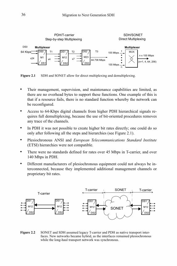
Migration to Next Generation SDH36
• Their management, supervision, and maintenance capabilities are limited, as there are no overhead bytes to support these functions. One example of this is that if a resource fails, there is no standard function whereby the network can be reconfigured.
• Access to 64-Kbps digital channels from higher PDH hierarchical signals re-quires full demultiplexing, because the use of bit-oriented procedures removes any trace of the channels.
• In PDH it was not possible to create higher bit rates directly; one could do so only after following all the steps and hierarchies (see Figure 2.1).
• Plesiochronous ANSI and European Telecommunications Standard Institute (ETSI) hierarchies were not compatible.
• There were no standards defined for rates over 45 Mbps in T-carrier, and over 140 Mbps in PDH.
• Different manufacturers of plesiochronous equipment could not always be in-terconnected, because they implemented additional management channels or proprietary bit rates.
Figure 2.1 SDH and SONET allow for direct multiplexing and demultiplexing.
MUX155 Mbps
Multiplexer
155 Mbps
1
n
n x 155 Mbps
DS2
x7x24
DS1
x4 44.736 Mbps
64 Kbps DS0
DS0
T1 T2 T3
DS1 DS3
M1 M12 M23
DS2(n=1, 4, 64, 256)
PDH/T-carrier SDH/SONET Step-by-step Multiplexing Direct Multiplexing
Multiplexer
Figure 2.2 SONET and SDH assumed legacy T-carrier and PDH as native transport inter-faces. New networks became hybrid, as the interfaces remained plesiochronous while the long-haul transport network was synchronous.
T-carrier SONET
DS1
M12
DS2
DS1
M12
DS2
DS1
M12
DS2
DS1
M12
DS2
SONET
T-carrierT-carrier
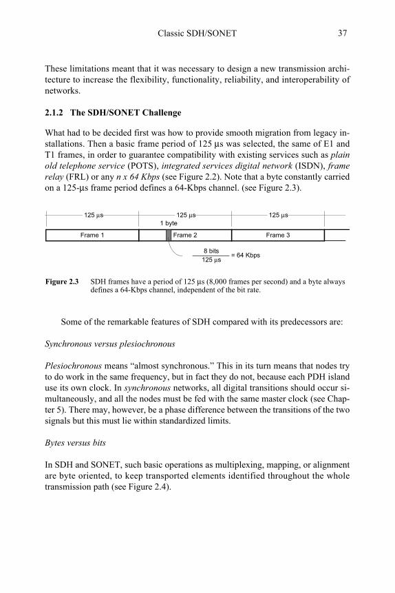
Classic SDH/SONET 37
These limitations meant that it was necessary to design a new transmission archi-tecture to increase the flexibility, functionality, reliability, and interoperability of networks.
2.1.2 The SDH/SONET Challenge
What had to be decided first was how to provide smooth migration from legacy in-stallations. Then a basic frame period of 125 μs was selected, the same of E1 and T1 frames, in order to guarantee compatibility with existing services such as plain old telephone service (POTS), integrated services digital network (ISDN), frame relay (FRL) or any n x 64 Kbps (see Figure 2.2). Note that a byte constantly carried on a 125-μs frame period defines a 64-Kbps channel. (see Figure 2.3).
Some of the remarkable features of SDH compared with its predecessors are:
Synchronous versus plesiochronous
Plesiochronous means “almost synchronous.” This in its turn means that nodes try to do work in the same frequency, but in fact they do not, because each PDH island use its own clock. In synchronous networks, all digital transitions should occur si-multaneously, and all the nodes must be fed with the same master clock (see Chap-ter 5). There may, however, be a phase difference between the transitions of the two signals but this must lie within standardized limits.
Bytes versus bits
In SDH and SONET, such basic operations as multiplexing, mapping, or alignment are byte oriented, to keep transported elements identified throughout the whole transmission path (see Figure 2.4).
Frame 3Frame 2Frame 1
Figure 2.3 SDH frames have a period of 125 μs (8,000 frames per second) and a byte always defines a 64-Kbps channel, independent of the bit rate.
125 μs
8 bits125 μs
= 64 Kbps
125 μs 125 μs1 byte
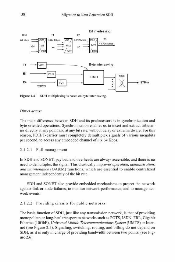
Migration to Next Generation SDH38
Direct access
The main difference between SDH and its predecessors is in synchronization and byte-oriented operations. Synchronization enables us to insert and extract tributar-ies directly at any point and at any bit rate, without delay or extra hardware. For this reason, PDH/T-carrier must completely demultiplex signals of various megabits per second, to access any embedded channel of n x 64 Kbps.
2.1.2.1 Full management
In SDH and SONET, payload and overheads are always accessible, and there is no need to demultiplex the signal. This drastically improves operation, administration, and maintenance (OA&M) functions, which are essential to enable centralized management independently of the bit rate.
SDH and SONET also provide embedded mechanisms to protect the network against link or node failures, to monitor network performance, and to manage net-work events.
2.1.2.2 Providing circuits for public networks
The basic function of SDH, just like any transmission network, is that of providing metropolitan or long-haul transport to networks such as POTS, ISDN, FRL, Gigabit Ethernet (10GbE), Universal Mobile Telecommunications System (UMTS) or Inter-net (see Figure 2.5). Signaling, switching, routing, and billing do not depend on SDH, as it is only in charge of providing bandwidth between two points. (see Fig-ure 2.6).
Figure 2.4 SDH multiplexing is based on byte interleaving.
DS2
x7x24
DS1
x4
44.736 Mbps
6.312 Mbps1.544 Mbps64 Kbps DS0
DS0 T1 T2
T3
DS1 DS3
M1 M12 M23
DS2
VC11T1
VC12E1
VC4E4
STM-1
Bit interleaving
mapping
MUX
Byte interleaving
STM-n
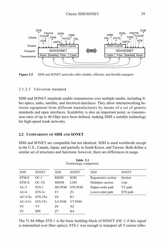
Classic SDH/SONET 39
2.1.2.3 Universal standard
SDH and SONET standards enable transmission over multiple media, including fi-ber optics, radio, satellite, and electrical interfaces. They allow internetworking be-tween equipment from different manufacturers by means of a set of generic standards and open interfaces. Scalability is also an important point, as transmis-sion rates of up to 40 Gbps have been defined, making SDH a suitable technology for high-speed trunk networks.
2.2 COMPARISON OF SDH AND SONET
SDH and SONET are compatible but not identical. SDH is used worldwide except in the U.S., Canada, Japan, and partially in South Korea, and Taiwan. Both define a similar set of structures and functions; however, there are differences in usage.
The 51.84-Mbps STS-1 is the basic building block of SONET (OC-1 if this signal is transmitted over fiber optics). STS-1 was enough to transport all T-carrier tribu-
Table 2.1Terminology comparison.
SDH SONET SDH SONET SDH SONET
STM-0 OC-1 RSOH SOH Regenerator section Section
STM-X OC-3X MSOH LOH Multiplex section Line
AU-3 STS-1 HO POH STS POH Higher-order path VT path
AU-4 STS-3c F3 Z3 Lower-order path STS path
AU-4-Xc STS-3Xc Z4 K3
AU-4-Yv STS-3Yv LO POH VT POH
TU VT Z6 N2
VC SPE Z7 K4
Figure 2.5 SDH and SONET networks offer reliable, efficient, and flexible transport.
Access
Transport
Transmission
DVB
TCP/IP
ATM10GE
UMTS
ISDN
POTSGSM
FRLClients
Internet
Cable SatelliteFiber Radio
PDH/T-carrier
DVB
TCP/IP
ATM10GE
UMTS
ISDN
POTSGSM
FRL
SDH/SONET
Internet
CableSatellite FiberRadio
PDH/T-carrier
SDH/SONET
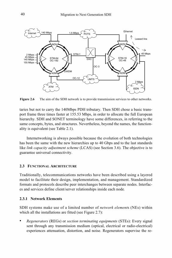
Figure 2.6 The aim of the SDH network is to provide transmission services to other networks.
Internet
ADM
AD
M
AD
M
ADM
STM-64OC-192
2 Mbps45 Mbps
140 Mbps DXC
ADM
AD
M
AD
M
ADM
STM-16OC-48
POTS
ATM
UMTS
Leased line
ISDN
Ethernet1,5 Mbps140 Mbps
2 Mbps
STM-1
OC-12
OC-3
45 Mbps
155 Mbps
DWDM
Migration to Next Generation SDH40
taries but not to carry the 140Mbps PDH tributary. Then SDH chose a basic trans-port frame three times faster at 155.53 Mbps, in order to allocate the full European hierarchy. SDH and SONET terminology have some differences, in referring to the same concepts, bytes, and structures. Nevertheless, beyond the names, the function-ality is equivalent (see Table 2.1).
Internetworking is always possible because the evolution of both technologies has been the same with the new hierarchies up to 40 Gbps and to the last standards like link capacity adjustment scheme (LCAS) (see Section 3.6). The objective is to guarantee universal connectivity.
2.3 FUNCTIONAL ARCHITECTURE
Traditionally, telecommunications networks have been described using a layered model to facilitate their design, implementation, and management. Standardized formats and protocols describe peer interchanges between separate nodes. Interfac-es and services define client/server relationships inside each node.
2.3.1 Network Elements
SDH systems make use of a limited number of network elements (NEs) within which all the installations are fitted (see Figure 2.7):
• Regenerators (REGs) or section terminating equipments (STEs): Every signal sent through any transmission medium (optical, electrical or radio-electrical) experiences attenuation, distortion, and noise. Regenerators supervise the re-
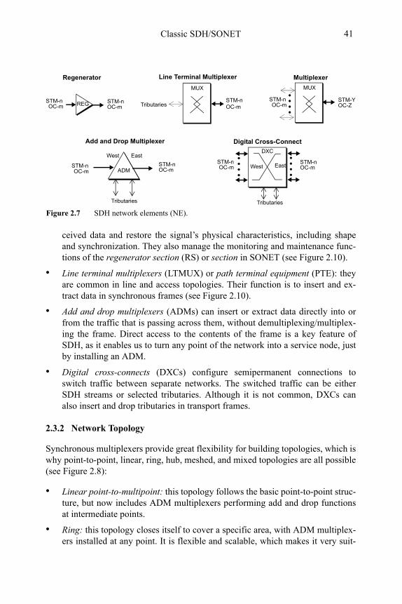
Classic SDH/SONET 41
ceived data and restore the signal’s physical characteristics, including shape and synchronization. They also manage the monitoring and maintenance func-tions of the regenerator section (RS) or section in SONET (see Figure 2.10).
• Line terminal multiplexers (LTMUX) or path terminal equipment (PTE): they are common in line and access topologies. Their function is to insert and ex-tract data in synchronous frames (see Figure 2.10).
• Add and drop multiplexers (ADMs) can insert or extract data directly into or from the traffic that is passing across them, without demultiplexing/multiplex-ing the frame. Direct access to the contents of the frame is a key feature of SDH, as it enables us to turn any point of the network into a service node, just by installing an ADM.
• Digital cross-connects (DXCs) configure semipermanent connections to switch traffic between separate networks. The switched traffic can be either SDH streams or selected tributaries. Although it is not common, DXCs can also insert and drop tributaries in transport frames.
2.3.2 Network Topology
Synchronous multiplexers provide great flexibility for building topologies, which is why point-to-point, linear, ring, hub, meshed, and mixed topologies are all possible (see Figure 2.8):
• Linear point-to-multipoint: this topology follows the basic point-to-point struc-ture, but now includes ADM multiplexers performing add and drop functions at intermediate points.
• Ring: this topology closes itself to cover a specific area, with ADM multiplex-ers installed at any point. It is flexible and scalable, which makes it very suit-
Figure 2.7 SDH network elements (NE).
Line Terminal Multiplexer
MUX
Add and Drop Multiplexer
REG
STM-nOC-m West
STM-nOC-m
STM-nOC-m
STM-nOC-m
STM-YOC-Z
Regenerator Multiplexer
Digital Cross-Connect
STM-nOC-m
STM-nOC-m
DXC
STM-nOC-m
East
West East
Tributaries
MUX
STM-nOC-m
Tributaries Tributaries
ADM
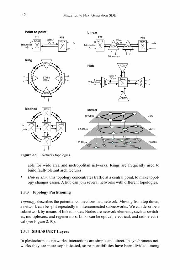
Migration to Next Generation SDH42
able for wide area and metropolitan networks. Rings are frequently used to build fault-tolerant architectures.
• Hub or star: this topology concentrates traffic at a central point, to make topol-ogy changes easier. A hub can join several networks with different topologies.
2.3.3 Topology Partitioning
Topology describes the potential connections in a network. Moving from top down, a network can be split repeatedly in interconnected subnetworks. We can describe a subnetwork by means of linked nodes. Nodes are network elements, such as switch-es, multiplexers, and regenerators. Links can be optical, electrical, and radioelectri-cal (see Figure 2.10).
2.3.4 SDH/SONET Layers
In plesiochronous networks, interactions are simple and direct. In synchronous net-works they are more sophisticated, so responsibilities have been divided among
PTE PTE
Figure 2.8 Network topologies.
Tributaries
ADM
AD
M
AD
M
ADM
STM-nOC-m
STM-nOC-m
Linear
Ring
ADM ADM
Tributaries
Meshed
AD
M
AD
M
ADM
ADM
STM-nOC-m
Hub
Core
Metro
Access
10 Gbps
2.5 Gbps
155 Mbps
Mixed
MUX MUX
DXC
DXC
DXC
DXCDXC
DXC
PTE PTE
Tributaries Tributaries
STM-nOC-m
Point to point
MUX MUX
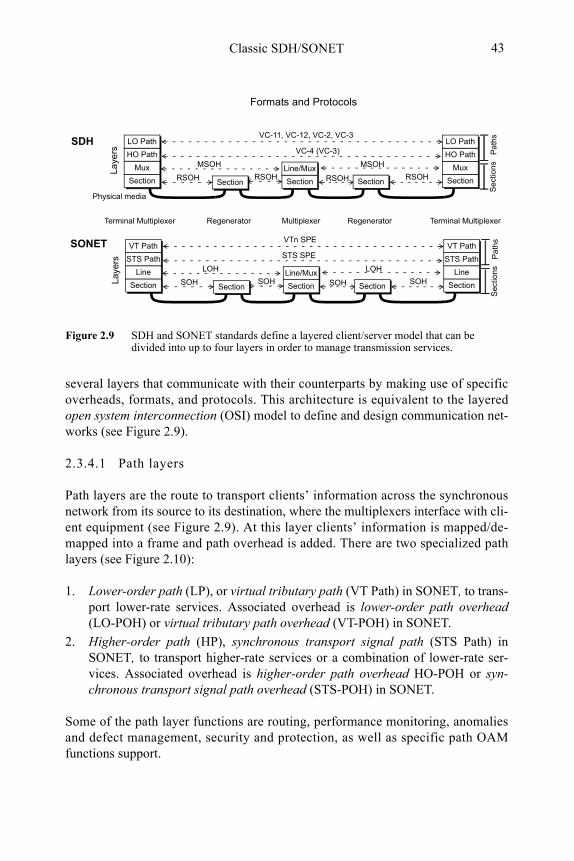
Classic SDH/SONET 43
several layers that communicate with their counterparts by making use of specific overheads, formats, and protocols. This architecture is equivalent to the layered open system interconnection (OSI) model to define and design communication net-works (see Figure 2.9).
2.3.4.1 Path layers
Path layers are the route to transport clients’ information across the synchronous network from its source to its destination, where the multiplexers interface with cli-ent equipment (see Figure 2.9). At this layer clients’ information is mapped/de-mapped into a frame and path overhead is added. There are two specialized path layers (see Figure 2.10):
1. Lower-order path (LP), or virtual tributary path (VT Path) in SONET, to trans-port lower-rate services. Associated overhead is lower-order path overhead (LO-POH) or virtual tributary path overhead (VT-POH) in SONET.
2. Higher-order path (HP), synchronous transport signal path (STS Path) in SONET, to transport higher-rate services or a combination of lower-rate ser-vices. Associated overhead is higher-order path overhead HO-POH or syn-chronous transport signal path overhead (STS-POH) in SONET.
Some of the path layer functions are routing, performance monitoring, anomalies and defect management, security and protection, as well as specific path OAM functions support.
Figure 2.9 SDH and SONET standards define a layered client/server model that can be divided into up to four layers in order to manage transmission services.
Section
Mux
HO Path
Section
Line/Mux
VC-4 (VC-3)
MSOH MSOH
RSOH
LO Path
Section
Mux
HO Path
LO Path VC-11, VC-12, VC-2, VC-3
RSOH RSOH
Pa
ths
Sec
tions
Formats and ProtocolsLa
yers
RSOHSection Section
Section
Line
STS Path
Section
Line/Mux
STS SPE
LOH LOH
SOH
VT Path
Section
Line
STS Path
VT PathVTn SPE
SOH SOH
Pa
ths
Sec
tions
Lay
ers
SOHSection Section
SDH
SONET
Terminal Multiplexer Multiplexer Terminal MultiplexerRegenerator Regenerator
Physical media
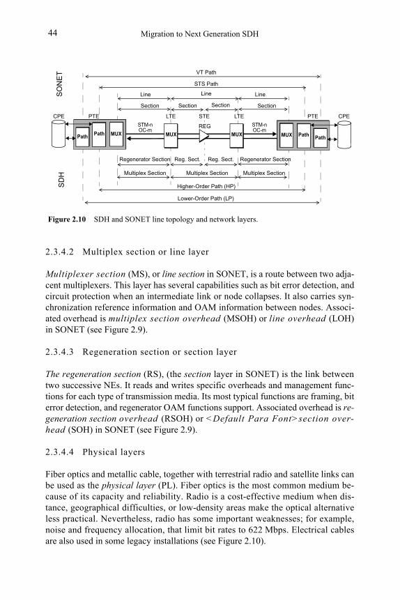
Migration to Next Generation SDH44
2.3.4.2 Multiplex section or line layer
Multiplexer section (MS), or line section in SONET, is a route between two adja-cent multiplexers. This layer has several capabilities such as bit error detection, and circuit protection when an intermediate link or node collapses. It also carries syn-chronization reference information and OAM information between nodes. Associ-ated overhead is multiplex section overhead (MSOH) or line overhead (LOH) in SONET (see Figure 2.9).
2.3.4.3 Regeneration section or section layer
The regeneration section (RS), (the section layer in SONET) is the link between two successive NEs. It reads and writes specific overheads and management func-tions for each type of transmission media. Its most typical functions are framing, bit error detection, and regenerator OAM functions support. Associated overhead is re-generation section overhead (RSOH) or <Default Para Font>section over-head (SOH) in SONET (see Figure 2.9).
2.3.4.4 Physical layers
Fiber optics and metallic cable, together with terrestrial radio and satellite links can be used as the physical layer (PL). Fiber optics is the most common medium be-cause of its capacity and reliability. Radio is a cost-effective medium when dis-tance, geographical difficulties, or low-density areas make the optical alternative less practical. Nevertheless, radio has some important weaknesses; for example, noise and frequency allocation, that limit bit rates to 622 Mbps. Electrical cables are also used in some legacy installations (see Figure 2.10).
Figure 2.10 SDH and SONET line topology and network layers.
Lower-Order Path (LP)
Higher-Order Path (HP)
Regenerator Section Reg. Sect.
Multiplex Section
Path MUX
PTE
MUX
STM-nOC-m
MUX
STS Path
VT Path
Line
Section
LineLine
Section SectionSection
SO
NE
T
REG
Reg. Sect. Regenerator Section
Multiplex SectionMultiplex Section
STM-nOC-m
Path
SD
H
CPE LTE STE LTE
PathMUX
PTE
Path
CPE
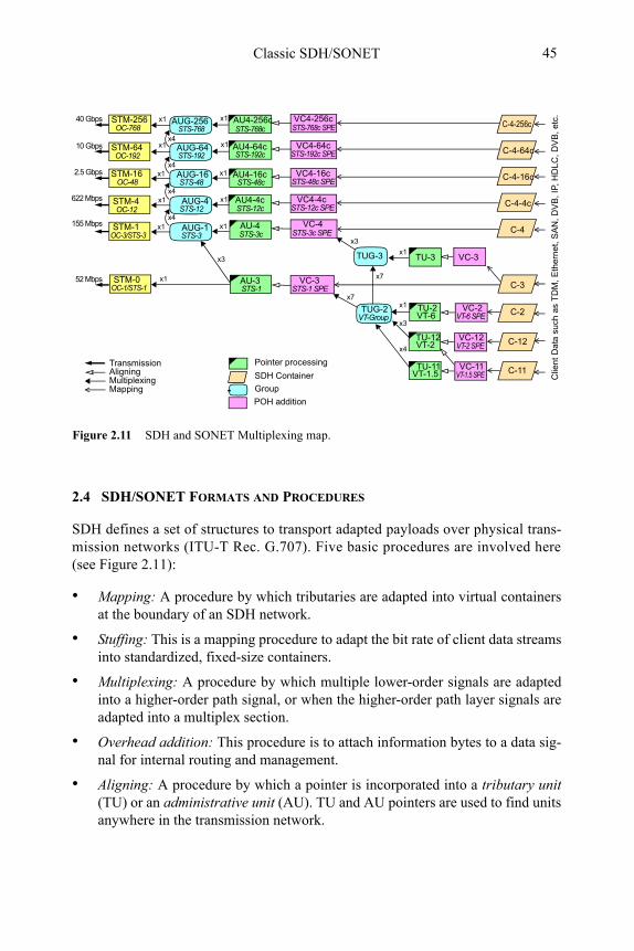
Classic SDH/SONET 45
2.4 SDH/SONET FORMATS AND PROCEDURES
SDH defines a set of structures to transport adapted payloads over physical trans-mission networks (ITU-T Rec. G.707). Five basic procedures are involved here (see Figure 2.11):
• Mapping: A procedure by which tributaries are adapted into virtual containers at the boundary of an SDH network.
• Stuffing: This is a mapping procedure to adapt the bit rate of client data streams into standardized, fixed-size containers.
• Multiplexing: A procedure by which multiple lower-order signals are adapted into a higher-order path signal, or when the higher-order path layer signals are adapted into a multiplex section.
• Overhead addition: This procedure is to attach information bytes to a data sig-nal for internal routing and management.
• Aligning: A procedure by which a pointer is incorporated into a tributary unit(TU) or an administrative unit (AU). TU and AU pointers are used to find units anywhere in the transmission network.
STM-1
STM-64
STM-16
STM-4
STM-256OC-768
OC-192
OC-48
OC-12
OC-3/STS-3
STM-0OC-1/STS-1
TUG-3
x3
x4
x7
x7
TUG-2
x3
x3
MappingMultiplexingAligning
Pointer processing
SDH Container
Group
VC-4
VC-3
VC4-4c
VC4-16c
AU-4
AU4-4c
AU4-16c
STS-3c SPE
STS-1 SPE
VT-Group
VC4-64c
VC4-256c
AU4-64c
AU4-256c
AU-3
AUG-256
STS-12c SPE
STS-48c SPE
STS-192c SPE
STS-768c SPE
STS-3c
STS-1
STS-12c
STS-48c
STS-192c
STS-768c STS-768
AUG-64STS-192
AUG-16STS-48
AUG-4STS-12
AUG-1STS-3
x4
x4
x4
x410 Gbps
2.5 Gbps
622 Mbps
155 Mbps
52 Mbps
Transmission
Figure 2.11 SDH and SONET Multiplexing map.
VC-3
VC-2
VC-12
VC-11
VT-6 SPE
VT-2 SPE
VT-1.5 SPE
POH addition
x1
x1
x1
x1
x1
x1
x1
x1
x1
x1
x1
x1
C-3
C-2
C-12
C-11
C-4-256c
C-4-64c
C-4-16c
C-4-4c
C-4
TU-3
TU-2
TU-12
TU-11
VT-6
VT-2
VT-1.5
x1
Clie
nt D
ata
su
ch a
s T
DM
, Eth
ern
et,
SA
N, D
VB
, IP,
HD
LC, D
VB
, etc
.40 Gbps
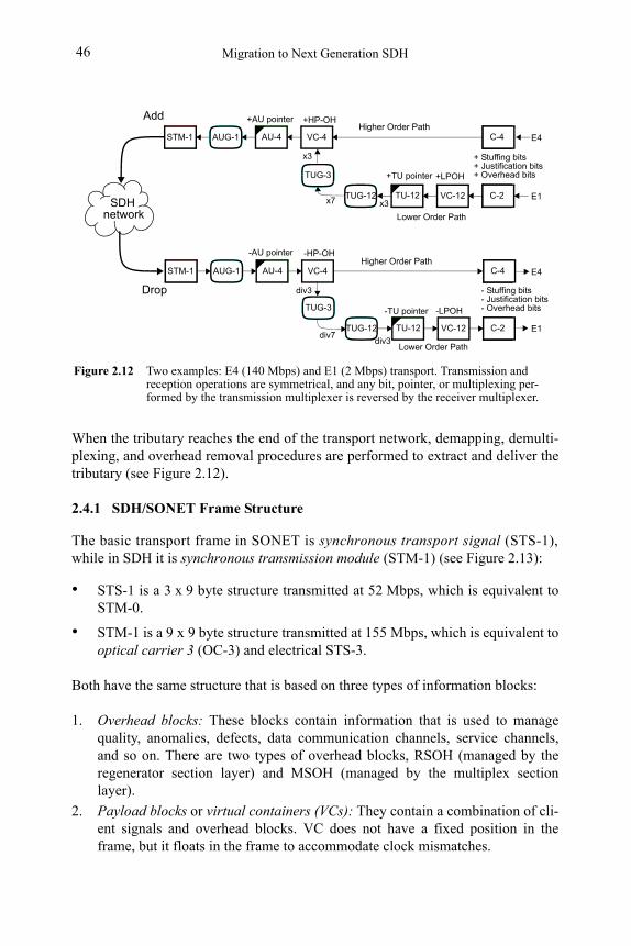
Migration to Next Generation SDH46
When the tributary reaches the end of the transport network, demapping, demulti-plexing, and overhead removal procedures are performed to extract and deliver the tributary (see Figure 2.12).
2.4.1 SDH/SONET Frame Structure
The basic transport frame in SONET is synchronous transport signal (STS-1), while in SDH it is synchronous transmission module (STM-1) (see Figure 2.13):
• STS-1 is a 3 x 9 byte structure transmitted at 52 Mbps, which is equivalent to STM-0.
• STM-1 is a 9 x 9 byte structure transmitted at 155 Mbps, which is equivalent to optical carrier 3 (OC-3) and electrical STS-3.
Both have the same structure that is based on three types of information blocks:
1. Overhead blocks: These blocks contain information that is used to manage quality, anomalies, defects, data communication channels, service channels, and so on. There are two types of overhead blocks, RSOH (managed by the regenerator section layer) and MSOH (managed by the multiplex section layer).
2. Payload blocks or virtual containers (VCs): They contain a combination of cli-ent signals and overhead blocks. VC does not have a fixed position in the frame, but it floats in the frame to accommodate clock mismatches.
Figure 2.12 Two examples: E4 (140 Mbps) and E1 (2 Mbps) transport. Transmission and reception operations are symmetrical, and any bit, pointer, or multiplexing per-formed by the transmission multiplexer is reversed by the receiver multiplexer.
C-4STM-1 VC-4AU-4
C-2VC-12TUG-12 TU-12
AUG-1
- Stuffing bits- Justification bits- Overhead bits
+LPOH
+AU pointer
+TU pointer
+HP-OH
E4
E1
C-4STM-1 VC-4AU-4
C-2VC-12TUG-12 TU-12
AUG-1
-LPOH
-AU pointer
-TU pointer
-HP-OH
E4
E1
Add
+ Stuffing bits+ Justification bits+ Overhead bits
Drop
Higher Order Path
SDHnetwork
TUG-3
TUG-3
x3
Higher Order Path
x7
Lower Order Path
Lower Order Path
x3
div3div7
div3
Classic SDH/SONET 47
3. Pointers: They track the VC position, pointing to its first byte, while moving inside the frame (see Figure 2.13).
2.4.1.1 Containers as transport interfaces
Containers (C-n) are used to map client bit streams. Adaptation procedures have been defined to suit most telecom transport requirements. These include PDH, met-ropolitan area network (MAN), asynchronous transfer mode (ATM), high-level data link control (HDLC), internet protocol (IP), and Ethernet streams.
Placing signals inside a container requires a stuffing function to match the client stream with the container capacity. The justification function is necessary for asyn-chronous mappings, to adapt clock differences and fluctuations.
2.4.1.2 Virtual containers or virtual tributaries
Virtual containers (VC-n) or virtual tributaries (VTs) in SONET (see Figure 2.14), support end-to-end path layer connections; that is, between the point where the cli-ent stream is inserted into the network and the point where it is delivered. Nobody is allowed to modify the VC contents across the entire path.
VCs consist of a C-n payload and a path overhead (POH). Fields are organized into a block structure that repeats every 125 or 500 μs. Containers hold client data, and the POH provides information to guarantee end-to-end data integrity.
There are two types of VCs:
• The lower-order VC, such as VC-11, VC-12, VC-2, and VC-31. These consist of a small container (C-11, C-12, C-2, and C-3), plus a 4-byte POH attached to the container (9 bytes for VC-3).
• The higher-order VC, such as VC-3 or VC-4. These consist of either a big con-tainer (C-3, C-4) or an assembly of tributary unit groups (TUG-2, TUG-3). In both cases, a 9-byte POH is attached.
2.4.1.3 Tributary units and tributary unit groups
A tributary unit is a structure for adaptation between the lower-order and higher-or-der path layer.
1. VC-3 can be transported through a lower-order path or a higher-order path, depending on the multiplexing map used (see Figure 2.11).
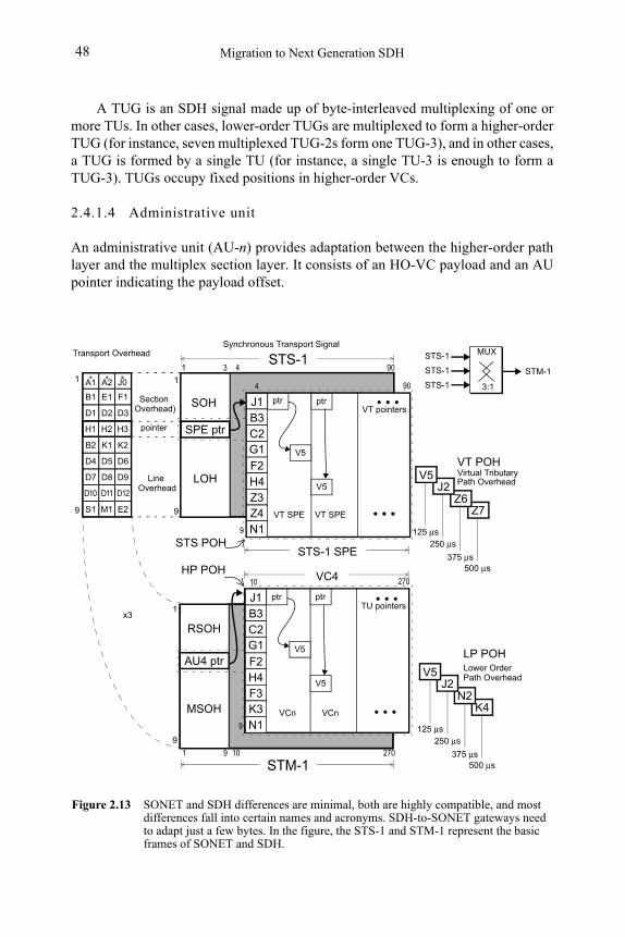
Migration to Next Generation SDH48
A TUG is an SDH signal made up of byte-interleaved multiplexing of one or more TUs. In other cases, lower-order TUGs are multiplexed to form a higher-order TUG (for instance, seven multiplexed TUG-2s form one TUG-3), and in other cases, a TUG is formed by a single TU (for instance, a single TU-3 is enough to form a TUG-3). TUGs occupy fixed positions in higher-order VCs.
2.4.1.4 Administrative unit
An administrative unit (AU-n) provides adaptation between the higher-order path layer and the multiplex section layer. It consists of an HO-VC payload and an AU pointer indicating the payload offset.
STS-1 SPE
Figure 2.13 SONET and SDH differences are minimal, both are highly compatible, and most differences fall into certain names and acronyms. SDH-to-SONET gateways need to adapt just a few bytes. In the figure, the STS-1 and STM-1 represent the basic frames of SONET and SDH.
904
SOH
LOH
SPE ptr
1 3STS-1
STS POH
90B1 E1
*A1 *A2 *
F1
D1 D2 D3
B2 K1 K2
D4 D5 D6
D7 D8 D9
S1 E2
D10 D11 D12
J0
M19
1
Section Overhead)
Line Overhead
9
1
H1 H2 H3 pointer
Transport Overhead
4
9
Synchronous Transport Signal
Z7
VT POH
Path OverheadVirtual Tributary
G1
F2H4
J1B3C2
Z3Z4N1
RSOH
MSOH
AU4 ptr
1
VC4 27010
9
G1
F2H4
J1B3C2
F3K3N1
270101 9
STM-1
HP POH
TU pointersptr ptr
V5
V5
Z6J2
V5
VT pointersptr ptr
V5
V5
VT SPE VT SPE
VCn VCn K4
LP POHLower Order
N2J2
V5
500 μs
Path Overhead
375 μs
250 μs125 μs
500 μs375 μs
250 μs125 μs
x3
MUX
STM-1
3:1
STS-1
STS-1
STS-1
9
1
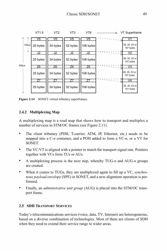
Classic SDH/SONET 49
2.4.2 Multiplexing Map
A multiplexing map is a road map that shows how to transport and multiplex a number of services in STM/OC frames (see Figure 2.11).
• The client tributary (PDH, T-carrier, ATM, IP, Ethernet, etc.) needs to be mapped into a C-n container, and a POH added to form a VC-n, or a VT for SONET.
• The VC/VT is aligned with a pointer to match the transport signal rate. Pointers together with VCs form TUs or AUs.
• A multiplexing process is the next step, whereby TUG-n and AUG-n groups are created.
• When it comes to TUGs, they are multiplexed again to fill up a VC, synchro-nous payload envelope (SPE) in SONET, and a new alignment operation is per-formed.
• Finally, an administrative unit group (AUG) is placed into the STM/OC trans-port frame.
2.5 SDH TRANSPORT SERVICES
Today’s telecommunications services (voice, data, TV, Internet) are heterogeneous, based on a diverse combination of technologies. Most of them are clients of SDH when they need to extend their service range to wider areas.
Figure 2.14 SONET virtual tributary superframes.
V5
25 bytes
J2
25 bytes
Z6
25 bytes
Z7
25 bytes
500μs
125μs
V5
34 bytes
J2
34 bytes
Z6
34 bytes
Z7
34 bytes
V5
52 bytes
J2
52 bytes
Z6
52 bytes
Z7
52 bytes
V5
106 bytes
J2
106 bytes
Z6
106 bytes
Z7
106 bytes
VT1.5 VT2 VT6VT3
V1
26, 35, 53 or
V2
V3
V4
107 bytes
26, 35, 53 or107 bytes
26, 35, 53 or107 bytes
26, 35, 53 or107 bytes
VT Superframe
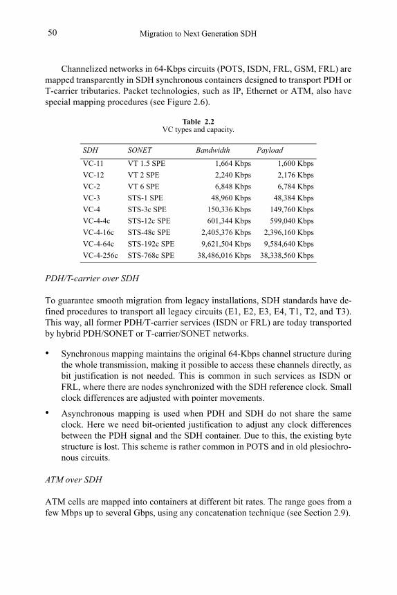
Migration to Next Generation SDH50
Channelized networks in 64-Kbps circuits (POTS, ISDN, FRL, GSM, FRL) are mapped transparently in SDH synchronous containers designed to transport PDH or T-carrier tributaries. Packet technologies, such as IP, Ethernet or ATM, also have special mapping procedures (see Figure 2.6).
PDH/T-carrier over SDH
To guarantee smooth migration from legacy installations, SDH standards have de-fined procedures to transport all legacy circuits (E1, E2, E3, E4, T1, T2, and T3). This way, all former PDH/T-carrier services (ISDN or FRL) are today transported by hybrid PDH/SONET or T-carrier/SONET networks.
• Synchronous mapping maintains the original 64-Kbps channel structure during the whole transmission, making it possible to access these channels directly, as bit justification is not needed. This is common in such services as ISDN or FRL, where there are nodes synchronized with the SDH reference clock. Small clock differences are adjusted with pointer movements.
• Asynchronous mapping is used when PDH and SDH do not share the same clock. Here we need bit-oriented justification to adjust any clock differences between the PDH signal and the SDH container. Due to this, the existing byte structure is lost. This scheme is rather common in POTS and in old plesiochro-nous circuits.
ATM over SDH
ATM cells are mapped into containers at different bit rates. The range goes from a few Mbps up to several Gbps, using any concatenation technique (see Section 2.9).
Table 2.2VC types and capacity.
SDH SONET Bandwidth Payload
VC-11 VT 1.5 SPE 1,664 Kbps 1,600 Kbps
VC-12 VT 2 SPE 2,240 Kbps 2,176 Kbps
VC-2 VT 6 SPE 6,848 Kbps 6,784 Kbps
VC-3 STS-1 SPE 48,960 Kbps 48,384 Kbps
VC-4 STS-3c SPE 150,336 Kbps 149,760 Kbps
VC-4-4c STS-12c SPE 601,344 Kbps 599,040 Kbps
VC-4-16c STS-48c SPE 2,405,376 Kbps 2,396,160 Kbps
VC-4-64c STS-192c SPE 9,621,504 Kbps 9,584,640 Kbps
VC-4-256c STS-768c SPE 38,486,016 Kbps 38,338,560 Kbps
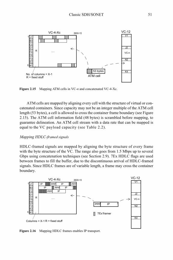
Classic SDH/SONET 51
ATM cells are mapped by aligning every cell with the structure of virtual or con-catenated containers. Since capacity may not be an integer multiple of the ATM cell length (53 bytes), a cell is allowed to cross the container frame boundary (see Figure 2.15). The ATM cell information field (48 bytes) is scrambled before mapping, to guarantee delineation. An ATM cell stream with a data rate that can be mapped is equal to the VC payload capacity (see Table 2.2).
Mapping HDLC-framed signals
HDLC-framed signals are mapped by aligning the byte structure of every frame with the byte structure of the VC. The range also goes from 1.5 Mbps up to several Gbps using concatenation techniques (see Section 2.9). 7Ex HDLC flags are used between frames to fill the buffer, due to the discontinuous arrival of HDLC-framed signals. Since HDLC frames are of variable length, a frame may cross the container boundary.
Figure 2.15 Mapping ATM cells in VC-n and concatenated VC-4-Xc.
G1
F2
H4
J1
B3
C2
F3
K3
N1
..... R
VC-4-Xc
No. of columns = X-1
260X+10
1
9
53 bytes
VC-12
ATM cell
V1
J2
N2
K4
VC-n
R = fixed stuff
Figure 2.16 Mapping HDLC frames enables IP transport.
PPP
G1
F2
H4
J1
B3
C2
F3
K3
N1
..... R
VC-4-Xc
Columns = X-1
260X+10
1
9
R = fixed stuff
IP
IP
PPP
PPP IP
PPP
IP
IP
PPP IP
‘7Ex‘framer
VC-12V1
J2
N2
K4
VC-n
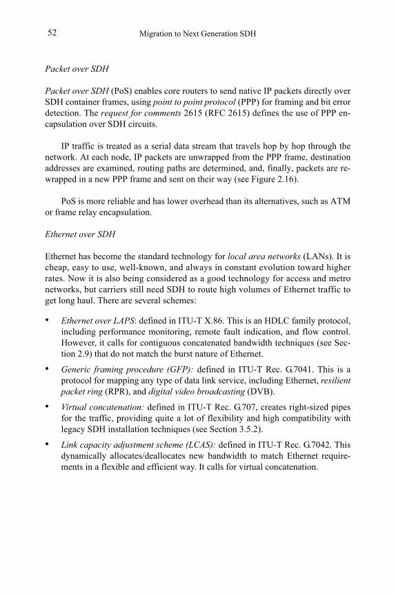
Migration to Next Generation SDH52
Packet over SDH
Packet over SDH (PoS) enables core routers to send native IP packets directly over SDH container frames, using point to point protocol (PPP) for framing and bit error detection. The request for comments 2615 (RFC 2615) defines the use of PPP en-capsulation over SDH circuits.
IP traffic is treated as a serial data stream that travels hop by hop through the network. At each node, IP packets are unwrapped from the PPP frame, destination addresses are examined, routing paths are determined, and, finally, packets are re-wrapped in a new PPP frame and sent on their way (see Figure 2.16).
PoS is more reliable and has lower overhead than its alternatives, such as ATM or frame relay encapsulation.
Ethernet over SDH
Ethernet has become the standard technology for local area networks (LANs). It is cheap, easy to use, well-known, and always in constant evolution toward higher rates. Now it is also being considered as a good technology for access and metro networks, but carriers still need SDH to route high volumes of Ethernet traffic to get long haul. There are several schemes:
• Ethernet over LAPS: defined in ITU-T X.86. This is an HDLC family protocol, including performance monitoring, remote fault indication, and flow control. However, it calls for contiguous concatenated bandwidth techniques (see Sec-tion 2.9) that do not match the burst nature of Ethernet.
• Generic framing procedure (GFP): defined in ITU-T Rec. G.7041. This is a protocol for mapping any type of data link service, including Ethernet, resilient packet ring (RPR), and digital video broadcasting (DVB).
• Virtual concatenation: defined in ITU-T Rec. G.707, creates right-sized pipes for the traffic, providing quite a lot of flexibility and high compatibility with legacy SDH installation techniques (see Section 3.5.2).
• Link capacity adjustment scheme (LCAS): defined in ITU-T Rec. G.7042. This dynamically allocates/deallocates new bandwidth to match Ethernet require-ments in a flexible and efficient way. It calls for virtual concatenation.
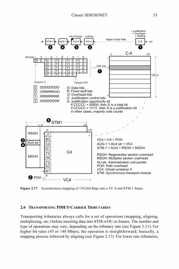
Classic SDH/SONET 53
2.6 TRANSPORTING PDH/T-CARRIER TRIBUTARIES
Transporting tributaries always calls for a set of operations (mapping, aligning, multiplexing, etc.) before inserting data into STM-n/OC-m frames. The number and type of operations may vary, depending on the tributary rate (see Figure 2.11). For higher bit rates (45 or 140 Mbps), the operation is straightforward; basically, a mapping process followed by aligning (see Figure 2.17). For lower rate tributaries,
Figure 2.17 Asynchronous mapping of 139,264 Kbps into a VC-4 and STM-1 frame.
27010
RSOH
MSOH
AU4 ptr
11 9
VC4 = C4 + POH
STM1
VC4
STM-1 = AUG + RSOH + MSOH
RSOH: Regenerator section overhead
AUG-1 = AU4 ptr + VC4
POH
MSOH: Multiplex section overheadAU ptr: Administration unit pointerPOH: Path overhead VC4: Virtual container 4STM: Synchronous transport module
D D X D Y D Y D Y D
X D Y D Z D
X D Y D Y D Y DX D Y D Y D Y DX D Y D Y D Y D
1 121 121 121 12260 bytes: 1 12
Column 11 Column 270
:DDDDDDDDD:CRRRRROOX:RRRRRRRRY
R: Fixed stuff bitsO: Overhead bitsC: Justification control bitsS: Justification opportunity bit
C-411
9
1
270
One row
27010
9
1
G1
F2H4
J1B3C2
F3K3N1
C4
C-4STM-1 VC-4AU-4AUG-1
+AU Pointer +HPOH
E4
+ Stuffing
Higher Order Path
+ Justification + Overhead
1234
5
1
2
3
4
if CCCCC = 00000, then S is a data bitif CCCCC = 11111, then S is a justification bit
5
:DDDDDDSRZ
D: Data bits
in other cases, majority vote counts
125 μs
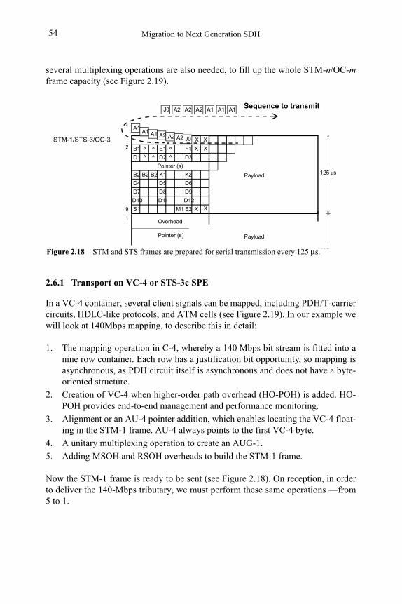
Migration to Next Generation SDH54
several multiplexing operations are also needed, to fill up the whole STM-n/OC-mframe capacity (see Figure 2.19).
2.6.1 Transport on VC-4 or STS-3c SPE
In a VC-4 container, several client signals can be mapped, including PDH/T-carrier circuits, HDLC-like protocols, and ATM cells (see Figure 2.19). In our example we will look at 140Mbps mapping, to describe this in detail:
1. The mapping operation in C-4, whereby a 140 Mbps bit stream is fitted into a nine row container. Each row has a justification bit opportunity, so mapping is asynchronous, as PDH circuit itself is asynchronous and does not have a byte-oriented structure.
2. Creation of VC-4 when higher-order path overhead (HO-POH) is added. HO-POH provides end-to-end management and performance monitoring.
3. Alignment or an AU-4 pointer addition, which enables locating the VC-4 float-ing in the STM-1 frame. AU-4 always points to the first VC-4 byte.
4. A unitary multiplexing operation to create an AUG-1.
5. Adding MSOH and RSOH overheads to build the STM-1 frame.
Now the STM-1 frame is ready to be sent (see Figure 2.18). On reception, in order to deliver the 140-Mbps tributary, we must perform these same operations —from 5 to 1.
125 μsPayload
B1 ^ ^ E1 ^
A1A1 A1 A2 A2 A2
F1
D1 ^ ^ D2 ^ D3
Pointer (s)
B2 B2 B2 K1 K2
D4 D5 D6
D7 D8 D9
S1 E2
D10 D11 D12
M1
STM-1/STS-3/OC-3X
X
X
X
X
J0
X9
1
2
A1A1A1A2A2A2J0
1
Pointer (s) Payload
Overhead
Sequence to transmit
125 μsFigure 2.18 STM and STS frames are prepared for serial transmission every 125 μs.
Classic SDH/SONET 55
2.6.2 Transport on VC-3
In a VC-3 container several client signals can be mapped, including PDH/T-carrier circuits, HDLC-like protocols, and ATM cells. Here, we will look at the 45-Mbps and 34-Mbps transport; in both cases all procedures except mapping are identical.
VC-3 has two transport schemes: (a) Lower-order (LO) transport, where VC-3s are allocated directly into the STM-1 frame; (b) Higher-order (HO) transport, where VC-3s are multiplexed into a VC-4 which is finally placed into the STM-1.
Higher-order transport
The operations and steps to follow are depicted in Figure 2.19:
1. The mapping operation in C-3. The 45 Mbps transport uses a one-row struc-ture, while for 34 Mbps, three rows are repeated three times.
2. A higher-order path overhead (HO-POH) addition to create a VC-3.
3. An alignment or an AU-3 pointer addition to locate the VC-3.
4. A unitary multiplexing operation to create an AUG-1.
5. Adding MSOH and RSOH overheads to build an STM-1 frame.
Now the STM-1 frame is ready to be sent. On reception, to deliver the tributary, we must perform the same operations vice versa; that is, from 5 to 1.
Lower-order transport
The operations and steps to follow are depicted in Figure 2.19:
1. Mapping is identical to that of higher-order transport.
b. A lower-order path overhead (LO-POH) addition to form a VC-3.
c. An alignment operation or AU-3 pointer addition to locate the VC-3. The new structure is called TU-3.
d. Multiplexing of three different TU-3s to create a TU-3 Group (TUG-3)
e. Adding an HO-POH to produce a VC-4.
f. A new alignment operation to find the VC-4.
g. A unitary multiplexing operation to create an AUG-1.
h. Adding MSOH and RSOH overheads to build an STM-1 frame.
The STM-1 frame is now ready to be sent. Again, to deliver the tributary, the same operations must be performed vice versa, from 8 to 1, on reception.
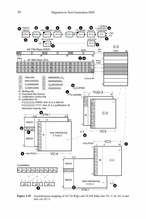
Migration to Next Generation SDH56
27010
RSOH
MSOH
AU4 ptr
9
11 9
STM-1
270
+HO-POH
9
110
G1
F2
H4
J1
B3
C2
F3
K3
N1
R
13
byte interleaving3 TUG-3
Figure 2.19 Asynchronous mapping of 44,736 Kbps and 34,368 Kbps into VC-3 via AU-4 and also via AU-3.
STM-1 VC-4AU-4 C-3VC-3TUG-3 TU-3AUG-1
+LPOH+AU-4 pointer
+TU pointer
+HPOH
E3
+ Stuffing+ Justification
+ Overhead +RSOH+MSOH
: Data bitsD
: RRCDDDDDK
: CCRRRRRRL
R: Stuffing bitsO: Overhead bits (future)C: Justification control bitsS: Justification bit
1 84
R DR DR D
RRR
X DX DS YZD
R D
Column 86
R K DD R L D R P D1 2 3 84
three
44 736 Kbps (DS3)
34 368 Kbps (E3)
: CCRROORSP
: RRRRRRC1C2X
: RRRRRRRS1A
: S2DDDDDDDB
C-3
9
2
84
rows
onerow
C-3
21TUG-3
VC3
G1F2H4
J1B3C2
F3K3N1
9
1
86
H1H2H3
R
x3
+LO-POH
C-3
ab
a
c
d
x 3
Bytes bytes
b
R DR DR D
R DR DR D
R DR DR D
R DR DR D
R DR DR D
RRR
R DR DR D
R DR DR D
R DR DR D
X DX DX D
5 9
R DR DR D
RRR
R DR DR D
R DR DR D
R DR DR D
R DR DR D
R DR DR D
RRR
R DR DR D
R DR DR D
R DR DR D
: SSSSSSSSS
if CiCiCiCiCi=11111, then Si is a justification bitif CiCiCiCiCi=00000, then Si is a data bit
Byte
DS3
10
RSOH
MSOH
9
11 9
STM-1
87+HO-POH
9
11
G1
F2
H4
J1
B3
C2
F3
K3
N1
R
4
C-3
VC-4
3 pointers
H1a H1b H1c H2a H2b H2c H3a H3b H3c
VC3
x 3
3xAU3 ptr
ptr a ptr b ptr c
f
g
e
cdefg
VC-3
+HO-POH
2AU-3
+AU-3 pointer
+TU pointer
3
2
x3
34
5
1
h
5 4
Byte-interleaving3 VC-3
28 56
otherwise majority vote
1
h
Classic SDH/SONET 57
Note that transporting VC-3 via AU-3 calls for three AU-3 pointers in the STM-1 frame. Pointer bytes appear interleaved in the space assigned for them in the structure of the synchronous transport module. In the case of VC-3 transport via AU-4, the first pointer indicates the beginning of the VC-4, and, inside the VC-4 payload, a second level of pointers is needed to locate VC-3 containers.
2.6.3 Transport of 2-Mbps Circuits
Transporting 2 Mbps can be synchronous or asynchronous. Synchronous mapping is possible only if PDH and SDH networks use the same reference clock. In this case, mapping has certain advantages because it is byte oriented, which means that the 64-Kbps frame structure of the tributary will be maintained throughout the whole transport, allowing direct access from SDH premises to the voice or data channel.
This does not happen in asynchronous mapping, as it has to use bit-oriented jus-tification mechanisms that break the E1 frame structure. Except for mapping, the op-eration sequence for both cases is similar (see Figures 2.20 and 2.21):
1. The mapping operation in container C-12. If asynchronous mapping is used, C-12 adopts a 500-μs multiframe format.
2. Adding lower-order path overhead to create VC-12.
3. Alignment or a TU pointer addition to indicate VC-12 offset. TU-2 is created this way.
4. Multiplexing of three TU-12s, which creates a TUG-2.
5. Multiplexing of seven TUG-2s, which creates a TUG-3.
6. A new multiplexing operation of three TUG-3s plus a HO-POH, together form a VC-4.
7. Alignment or an AU-4 pointer addition enables us to locate the VC-4.
8. A unitary multiplexing operation to create an AUG-1.
9. Adding MSOH and RSOH overheads to build an STM-1 frame.
10. Since VC-12 is a multiframe, then transmission is a four STM-1 multiframe operation (see Figure 2.22).
The STM-1 frame can now be sent. On reception, to deliver the 2-Mbps circuit, we must again perform these operations vice versa, from 9 to 1. Note the VC-4 capaci-ty up to 63 x 2 Mbps circuits can be transported simultaneously.
At the reception end, to locate each circuit, we must first find the VC-4 using the AU-4 pointer and then, by reading the TU-12 pointer, it is possible to find the VC-12 offset.
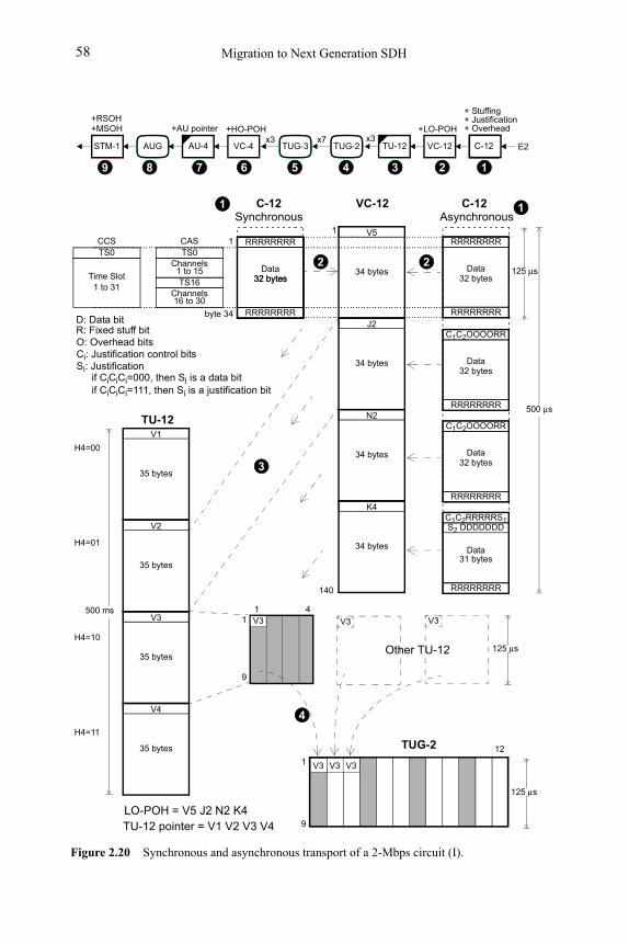
Migration to Next Generation SDH58
V5
34 bytes
J2
34 bytes
N2
34 bytes
K4
34 bytes
Data32 bytes
Figure 2.20 Synchronous and asynchronous transport of a 2-Mbps circuit (I).
Synchronous
125 μs
500 μs
R: Fixed stuff bitO: Overhead bitsCi: Justification control bitsSi: Justification
D: Data bit
STM-1 VC-4AU-4 C-12VC-12TUG-2 TU-12AUG
+LO-POH+AU pointer +HO-POH
E2
+ Stuffing+ Justification+ Overhead
+RSOH+MSOH
x3
12346789
TUG-3
5
x7x3
S2 DDDDDDDC1C2RRRRRS1
TS0Channels
1 to 15TS16
Channels16 to 30
CAS RRRRRRRR
RRRRRRRR
32 bytes
RRRRRRRR
RRRRRRRR
Data32 bytes
C1C2OOOORR
RRRRRRRR
Data32 bytes
C1C2OOOORR
RRRRRRRR
Data32 bytes
RRRRRRRR
Data31 bytes
Asynchronous
TS0
Time Slot1 to 31
CCS 1
byte 34
VC-12
22
11 C-12C-12
V1
35 bytes
V2
35 bytes
V3
35 bytes
V4
35 bytes
500 ms
3
TU-12
H4=00
H4=01
H4=10
H4=11
V311 4
9
125 μs
9
12
V3 V3
4
TUG-2
1
140
V3 V3V31
Other TU-12
LO-POH = V5 J2 N2 K4TU-12 pointer = V1 V2 V3 V4
125 μs
if CiCiCi=111, then Si is a justification bitif CiCiCi=000, then Si is a data bit
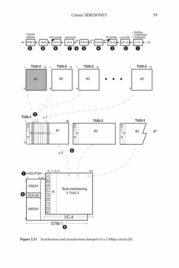
RSOH
MSOH
AU4 ptr
R
NPI
Figure 2.21 Synchronous and asynchronous transport of a 2-Mbps circuit (II).
STM-1 VC-4AU-4 C-12VC-12TUG-2 TU-12AUG
+LO-POH+AU pointer +HO-POH
E2
+ Stuffing+ Justification+ Overhead
+RSOH+MSOH
x3
12346789
TUG-3
5
x7x3
9
1 TUG-2 12
9
86
TUG-31
9
1 TUG-2 12
9
1 TUG-2 12
#1 #2 #7
9
1 TUG-2 12
#3
R
1 2 3 4 5 6 7 1 2.......
5
TUG-3x 7
TUG-3
R
NPI
R
R
NPI
R
10
9
11 9
VC-4
270+HO-POH
10
G1
F2
H4
J1
B3
C2
F3
K3
N1
R
13
6
Byte-interleaving3 TUG-3
7
8
STM-19
TU pointer
x 3
8
#1 #2 #3
11 12
. . . #7
Classic SDH/SONET 59
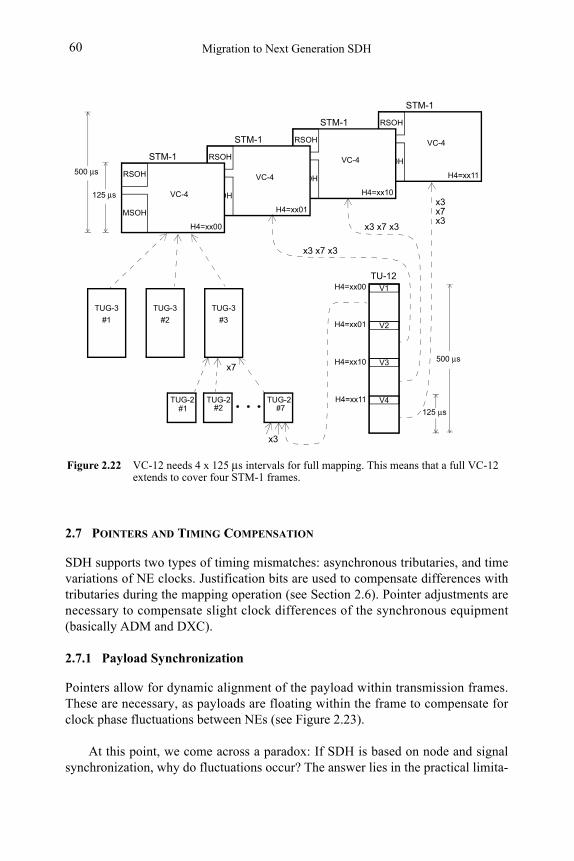
Figure 2.22 VC-12 needs 4 x 125 μs intervals for full mapping. This means that a full VC-12 extends to cover four STM-1 frames.
VC-4
RSOH
MSOH
125 μs
500 μs
V1
V2
V3
V4
H4=xx00
H4=xx01
H4=xx10
H4=xx11
TU-12
125 μs
TUG-2 TUG-2 TUG-2#1 #2 #7
500 μs H4=xx11
STM-1
TUG-3
#1
TUG-3
#2
TUG-3
#3
VC-4
RSOH
MSOH
H4=xx10
STM-1
VC-4
RSOH
MSOH
H4=xx01
STM-1
VC-4
RSOH
MSOH
H4=xx00
STM-1
x7
x3
x3 x7 x3
x3 x7 x3
x3x7x3
Migration to Next Generation SDH60
2.7 POINTERS AND TIMING COMPENSATION
SDH supports two types of timing mismatches: asynchronous tributaries, and time variations of NE clocks. Justification bits are used to compensate differences with tributaries during the mapping operation (see Section 2.6). Pointer adjustments are necessary to compensate slight clock differences of the synchronous equipment (basically ADM and DXC).
2.7.1 Payload Synchronization
Pointers allow for dynamic alignment of the payload within transmission frames. These are necessary, as payloads are floating within the frame to compensate for clock phase fluctuations between NEs (see Figure 2.23).
At this point, we come across a paradox: If SDH is based on node and signal synchronization, why do fluctuations occur? The answer lies in the practical limita-
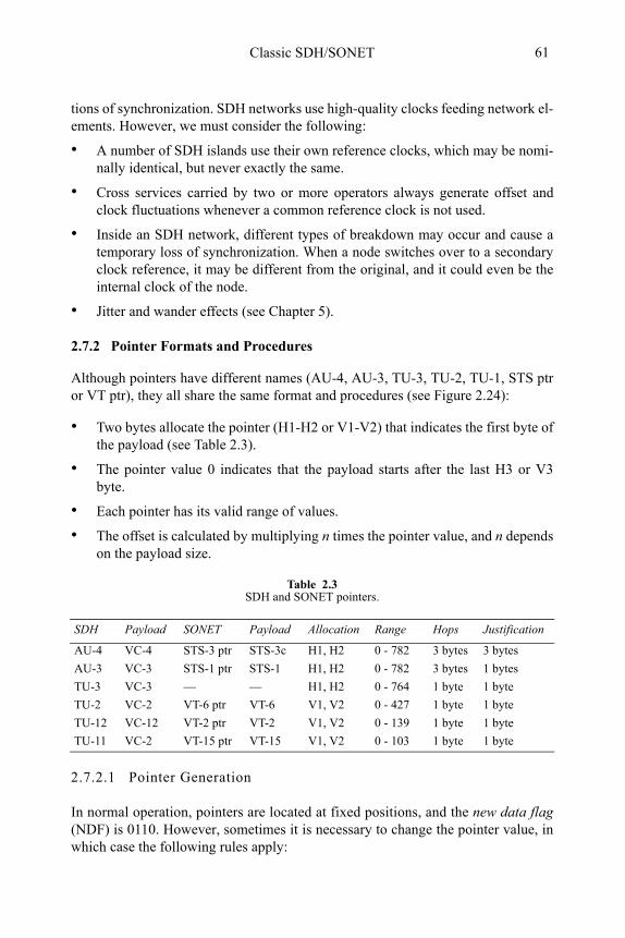
Classic SDH/SONET 61
tions of synchronization. SDH networks use high-quality clocks feeding network el-ements. However, we must consider the following:
• A number of SDH islands use their own reference clocks, which may be nomi-nally identical, but never exactly the same.
• Cross services carried by two or more operators always generate offset and clock fluctuations whenever a common reference clock is not used.
• Inside an SDH network, different types of breakdown may occur and cause a temporary loss of synchronization. When a node switches over to a secondary clock reference, it may be different from the original, and it could even be the internal clock of the node.
• Jitter and wander effects (see Chapter 5).
2.7.2 Pointer Formats and Procedures
Although pointers have different names (AU-4, AU-3, TU-3, TU-2, TU-1, STS ptr or VT ptr), they all share the same format and procedures (see Figure 2.24):
• Two bytes allocate the pointer (H1-H2 or V1-V2) that indicates the first byte of the payload (see Table 2.3).
• The pointer value 0 indicates that the payload starts after the last H3 or V3 byte.
• Each pointer has its valid range of values.
• The offset is calculated by multiplying n times the pointer value, and n depends on the payload size.
2.7.2.1 Pointer Generation
In normal operation, pointers are located at fixed positions, and the new data flag(NDF) is 0110. However, sometimes it is necessary to change the pointer value, in which case the following rules apply:
Table 2.3SDH and SONET pointers.
SDH Payload SONET Payload Allocation Range Hops Justification
AU-4 VC-4 STS-3 ptr STS-3c H1, H2 0 - 782 3 bytes 3 bytes
AU-3 VC-3 STS-1 ptr STS-1 H1, H2 0 - 782 3 bytes 1 bytes
TU-3 VC-3 — — H1, H2 0 - 764 1 byte 1 byte
TU-2 VC-2 VT-6 ptr VT-6 V1, V2 0 - 427 1 byte 1 byte
TU-12 VC-12 VT-2 ptr VT-2 V1, V2 0 - 139 1 byte 1 byte
TU-11 VC-2 VT-15 ptr VT-15 V1, V2 0 - 103 1 byte 1 byte
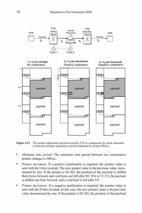
Migration to Next Generation SDH62
• Minimum time period: The minimum time period between two consecutive pointer changes is 500 μs.
• Pointer increment: If a positive justification is required, the pointer value is sent with the I-bits inverted. The new pointer value is the previous value, incre-mented by one. If the pointer is H1-H2, the position of the payload is shifted three bytes forward, and void bytes are left after H3. If it is V1-V2, the payload is shifted one byte forward, and a void byte is left after V3.
• Pointer decrement: If a negative justification is required, the pointer value is sent with the D-bits inverted. In this case, the new pointer value is the previous value decremented by one. If the pointer is H1-H2, the position of the payload
Figure 2.23 The pointer adjustment operation used by LTE to compensate for clock mismatch. Consecutive pointer operations must be separated by at least 500 μs.
J1
J1
J1
payload
payload
payload
No Justification
J1
payload
payload
VC-4
J1
J1
payload
payload
Positive Justification Negative Justification
J1
payload
J1
0000
J1
payload
12
5μsH2H1 H3
0H2H1 H3
H2H1 H3
H2H1 H3
H2H1 H3
H2H1 H3
H2H1 H3
H2H1 H3
H2H1 H3
00
ADM
MUX MUXCPE CPE
fo f1
Clock-2
f2
Clock-1
Tributary
fo
Tributary
Stuffing PointerMovement
Destuffing
f1 = f2 (no change) f1 > f2 (ptr decrement) f1 < f2 (ptr increment)
PTE PTE
n
n+1
n+2
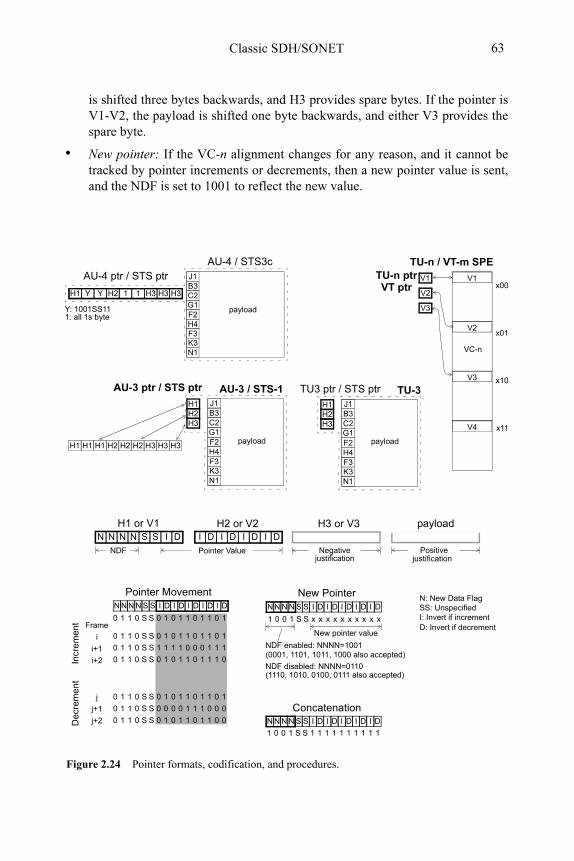
Classic SDH/SONET 63
is shifted three bytes backwards, and H3 provides spare bytes. If the pointer is V1-V2, the payload is shifted one byte backwards, and either V3 provides the spare byte.
• New pointer: If the VC-n alignment changes for any reason, and it cannot be tracked by pointer increments or decrements, then a new pointer value is sent, and the NDF is set to 1001 to reflect the new value.
N N N N S S I D I D I D I D I D
Pointer Value
H1 or V1 H2 or V2
SS: Unspecified I: Invert if increment
Concatenation
NDF
N N N N S S I D I D I D I D I D
0 1 1 0 S S 0 1 0 1 1 0 1 1 0 1
0 1 1 0 S S 1 1 1 1 0 0 0 1 1 1
0 1 1 0 S S 0 1 0 1 1 0 1 1 1 0
0 1 1 0 S S 0 0 0 0 1 1 1 0 0 0
0 1 1 0 S S 0 1 0 1 1 0 1 1 0 0
0 1 1 0 S S 0 1 0 1 1 0 1 1 0 1
0 1 1 0 S S 0 1 0 1 1 0 1 1 0 1
i
i+1
i+2
j
j+1
j+2
Frame
Incr
emen
tD
ecre
me
nt
Pointer MovementN N N N S S I D I D I D I D I D
1 0 0 1 S S x x x x x x x x x x
New Pointer
NDF enabled: NNNN=1001
N: New Data Flag
NDF disabled: NNNN=0110
(0001, 1101, 1011, 1000 also accepted)
(1110, 1010, 0100, 0111 also accepted)
New pointer value
H3 or V3
Negativejustification
payload
Positivejustification
Figure 2.24 Pointer formats, codification, and procedures.
D: Invert if decrement
1 0 0 1 S S 1 1 1 1 1 1 1 1 1 1
C-3G1F2H4
J1B3C2
F3K3N1
H1H2H3
AU-4 ptr / STS ptr
G1F2H4
J1B3C2
F3K3N1
YH1 Y 1H2 1 H3H3 H3
AU-4 / STS3c
TU-3
Y: 1001SS111: all 1s byte
V1
V2
V3
V4
TU-n / VT-m SPE
x00
x01
x10
x11
payload
N N N N S S I D I D I D I D I D
H1H1 H1 H2H2 H2 H3H3 H3
AU-3 / STS-1AU-3 ptr / STS ptr
C-3G1F2H4
J1B3C2
F3K3N1
H1H2H3
payload
TU3 ptr / STS ptr
V1
V2
V3
TU-n ptr
VC-n
VT ptr
payload
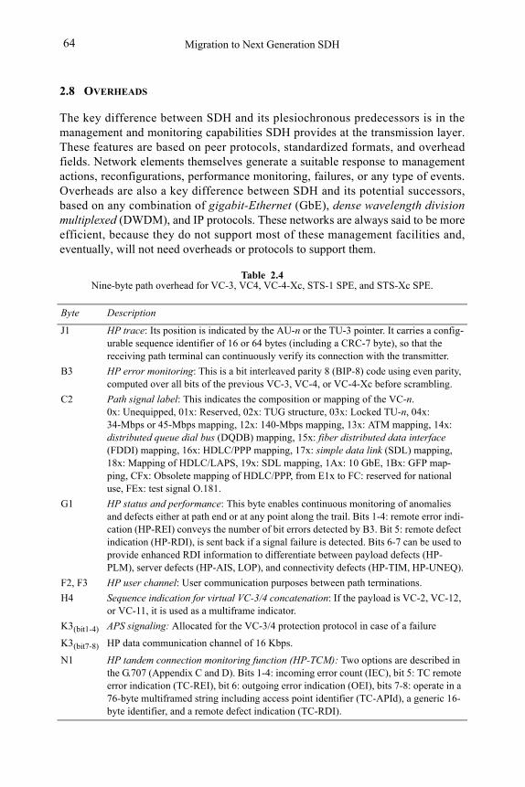
Migration to Next Generation SDH64
2.8 OVERHEADS
The key difference between SDH and its plesiochronous predecessors is in the management and monitoring capabilities SDH provides at the transmission layer. These features are based on peer protocols, standardized formats, and overhead fields. Network elements themselves generate a suitable response to management actions, reconfigurations, performance monitoring, failures, or any type of events. Overheads are also a key difference between SDH and its potential successors, based on any combination of gigabit-Ethernet (GbE), dense wavelength division multiplexed (DWDM), and IP protocols. These networks are always said to be more efficient, because they do not support most of these management facilities and, eventually, will not need overheads or protocols to support them.
Table 2.4Nine-byte path overhead for VC-3, VC4, VC-4-Xc, STS-1 SPE, and STS-Xc SPE.
Byte Description
J1 HP trace: Its position is indicated by the AU-n or the TU-3 pointer. It carries a config-urable sequence identifier of 16 or 64 bytes (including a CRC-7 byte), so that the receiving path terminal can continuously verify its connection with the transmitter.
B3 HP error monitoring: This is a bit interleaved parity 8 (BIP-8) code using even parity, computed over all bits of the previous VC-3, VC-4, or VC-4-Xc before scrambling.
C2 Path signal label: This indicates the composition or mapping of the VC-n. 0x: Unequipped, 01x: Reserved, 02x: TUG structure, 03x: Locked TU-n, 04x: 34-Mbps or 45-Mbps mapping, 12x: 140-Mbps mapping, 13x: ATM mapping, 14x: distributed queue dial bus (DQDB) mapping, 15x: fiber distributed data interface (FDDI) mapping, 16x: HDLC/PPP mapping, 17x: simple data link (SDL) mapping, 18x: Mapping of HDLC/LAPS, 19x: SDL mapping, 1Ax: 10 GbE, 1Bx: GFP map-ping, CFx: Obsolete mapping of HDLC/PPP, from E1x to FC: reserved for national use, FEx: test signal O.181.
G1 HP status and performance: This byte enables continuous monitoring of anomalies and defects either at path end or at any point along the trail. Bits 1-4: remote error indi-cation (HP-REI) conveys the number of bit errors detected by B3. Bit 5: remote defect indication (HP-RDI), is sent back if a signal failure is detected. Bits 6-7 can be used to provide enhanced RDI information to differentiate between payload defects (HP-PLM), server defects (HP-AIS, LOP), and connectivity defects (HP-TIM, HP-UNEQ).
F2, F3 HP user channel: User communication purposes between path terminations.
H4 Sequence indication for virtual VC-3/4 concatenation: If the payload is VC-2, VC-12, or VC-11, it is used as a multiframe indicator.
K3(bit1-4) APS signaling: Allocated for the VC-3/4 protection protocol in case of a failure
K3(bit7-8) HP data communication channel of 16 Kbps.
N1 HP tandem connection monitoring function (HP-TCM): Two options are described in the G.707 (Appendix C and D). Bits 1-4: incoming error count (IEC), bit 5: TC remote error indication (TC-REI), bit 6: outgoing error indication (OEI), bits 7-8: operate in a 76-byte multiframed string including access point identifier (TC-APId), a generic 16-byte identifier, and a remote defect indication (TC-RDI).
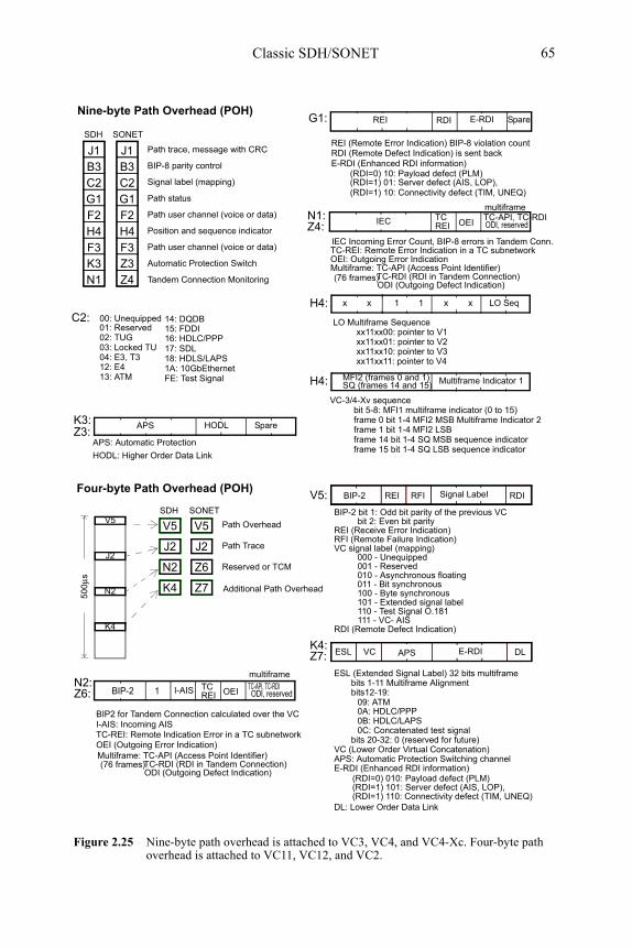
REI (Remote Error Indication) BIP-8 violation count
REI RDIG1:
RDI (Remote Defect Indication) is sent back
00: Unequipped01: Reserved02: TUG03: Locked TU04: E3, T3
14: DQDB15: FDDI xx11xx00: pointer to V1
xx11xx01: pointer to V2xx11xx10: pointer to V3xx11xx11: pointer to V4
Nine-byte Path Overhead (POH)
Path trace, message with CRC
BIP-8 parity control
Signal label (mapping)
Path status
Path user channel (voice or data)
Position and sequence indicator
Path user channel (voice or data)
Automatic Protection Switch
Tandem Connection Monitoring
G1F2H4
J1B3C2
F3Z3Z4
16: HDLC/PPP
18: HDLS/LAPS1A: 10GbEthernetFE: Test Signal
SpareE-RDI
IEC Incoming Error Count, BIP-8 errors in Tandem Conn.
IEC TCN1:REI OEI
TC-API, TC-RDIODI, reserved
E-RDI (Enhanced RDI information)
TC-REI: Remote Error Indication in a TC subnetworkOEI: Outgoing Error IndicationMultiframe: TC-API (Access Point Identifier)
multiframe
17: SDL
(RDI=0) 10: Payload defect (PLM)(RDI=1) 01: Server defect (AIS, LOP), (RDI=1) 10: Connectivity defect (TIM, UNEQ)
LO Multiframe Sequence
BIP-2V5:
ESL (Extended Signal Label) 32 bits multiframe
REI RFI RDI
BIP-2 bit 1: Odd bit parity of the previous VCbit 2: Even bit parity
Signal Label
RDI (Remote Defect Indication)
VC signal label (mapping)000 - Unequipped001 - Reserved010 - Asynchronous floating011 - Bit synchronous 100 - Byte synchronous
Path Overhead
Reserved or TCM
APS: Automatic Protection Switching channel
Path Trace
V5
J2
N2
K4
V5
J2
N2
K4
50
0μs
101 - Extended signal label110 - Test Signal O.181
Additional Path Overhead
REI (Receive Error Indication)RFI (Remote Failure Indication)
bits 1-11 Multiframe Alignmentbits12-19:
0A: HDLC/PPP0B: HDLC/LAPS0C: Concatenated test signal
DL: Lower Order Data Link
BIP2 for Tandem Connection calculated over the VC
BIP-2 I-AISN2:
OEITC-API, TC-RDIODI, reserved
TC-REI: Remote Indication Error in a TC subnetworkOEI (Outgoing Error Indication)
multiframe
1 TCREI
I-AIS: Incoming AIS
111 - VC- AIS
K4:APS DLE-RDIESL VC
Figure 2.25 Nine-byte path overhead is attached to VC3, VC4, and VC4-Xc. Four-byte path overhead is attached to VC11, VC12, and VC2.
Four-byte Path Overhead (POH)
bits 20-32: 0 (reserved for future)VC (Lower Order Virtual Concatenation)
ODI (Outgoing Defect Indication)
VC-3/4-Xv sequencebit 5-8: MFI1 multiframe indicator (0 to 15)frame 0 bit 1-4 MFI2 MSB Multiframe Indicator 2frame 1 bit 1-4 MFI2 LSBframe 14 bit 1-4 SQ MSB sequence indicatorframe 15 bit 1-4 SQ LSB sequence indicator
12: E413: ATM
H4: LO Seqx
C2:
APS: Automatic Protection
K3:
HODL: Higher Order Data Link
xx x 1 1
H4: Multiframe Indicator 1MFI2 (frames 0 and 1)SQ (frames 14 and 15)
09: ATM
E-RDI (Enhanced RDI information)(RDI=0) 010: Payload defect (PLM)(RDI=1) 101: Server defect (AIS, LOP), (RDI=1) 110: Connectivity defect (TIM, UNEQ)
TC-RDI (RDI in Tandem Connection)
Multiframe: TC-API (Access Point Identifier)
ODI (Outgoing Defect Indication)TC-RDI (RDI in Tandem Connection)
G1F2H4
J1B3C2
F3K3N1
SDH SONET
V5
J2
Z6
Z7
SDH SONET
APS SpareHODL
(76 frames)
(76 frames)
Z3:
Z6:
Z7:
Z4:
Classic SDH/SONET 65
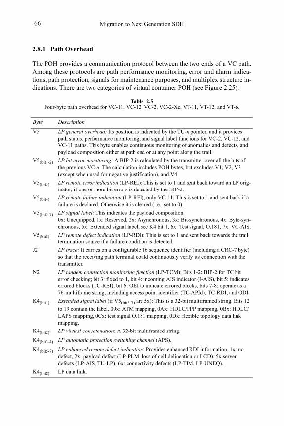
Migration to Next Generation SDH66
2.8.1 Path Overhead
The POH provides a communication protocol between the two ends of a VC path. Among these protocols are path performance monitoring, error and alarm indica-tions, path protection, signals for maintenance purposes, and multiplex structure in-dications. There are two categories of virtual container POH (see Figure 2.25):
Table 2.5Four-byte path overhead for VC-11, VC-12, VC-2, VC-2-Xc, VT-11, VT-12, and VT-6.
Byte Description
V5 LP general overhead: Its position is indicated by the TU-n pointer, and it provides path status, performance monitoring, and signal label functions for VC-2, VC-12, and VC-11 paths. This byte enables continuous monitoring of anomalies and defects, and payload composition either at path end or at any point along the trail.
V5(bit1-2) LP bit error monitoring: A BIP-2 is calculated by the transmitter over all the bits of the previous VC-n. The calculation includes POH bytes, but excludes V1, V2, V3 (except when used for negative justification), and V4.
V5(bit3) LP remote error indication (LP-REI): This is set to 1 and sent back toward an LP orig-inator, if one or more bit errors is detected by the BIP-2.
V5(bit4) LP remote failure indication (LP-RFI), only VC-11: This is set to 1 and sent back if a failure is declared. Otherwise it is cleared (i.e., set to 0).
V5(bit5-7) LP signal label: This indicates the payload composition. 0x: Unequipped, 1x: Reserved, 2x: Asynchronous, 3x: Bit-synchronous, 4x: Byte-syn-chronous, 5x: Extended signal label, see K4 bit 1, 6x: Test signal, O.181, 7x: VC-AIS.
V5(bit8) LP remote defect indication (LP-RDI): This is set to 1 and sent back towards the trail termination source if a failure condition is detected.
J2 LP trace: It carries on a configurable 16 sequence identifier (including a CRC-7 byte) so that the receiving path terminal could continuously verify its connection with the transmitter.
N2 LP tandem connection monitoring function (LP-TCM): Bits 1-2: BIP-2 for TC bit error checking; bit 3: fixed to 1, bit 4: incoming AIS indicator (I-AIS), bit 5: indicates errored blocks (TC-REI), bit 6: OEI to indicate errored blocks, bits 7-8: operate as a 76-multiframe string, including access point identifier (TC-APId), TC-RDI, and ODI.
K4(bit1) Extended signal label (if V5(bit5-7) are 5x): This is a 32-bit multiframed string. Bits 12
to 19 contain the label. 09x: ATM mapping, 0Ax: HDLC/PPP mapping, 0Bx: HDLC/LAPS mapping, 0Cx: test signal O.181 mapping, 0Dx: flexible topology data link mapping.
K4(bit2) LP virtual concatenation: A 32-bit multiframed string.
K4(bit3-4) LP automatic protection switching channel (APS).
K4(bit5-7) LP enhanced remote defect indication: Provides enhanced RDI information. 1x: no defect, 2x: payload defect (LP-PLM; loss of cell delineation or LCD), 5x server defects (LP-AIS, TU-LP), 6x: connectivity defects (LP-TIM, LP-UNEQ).
K4(bit8) LP data link.
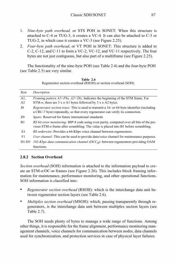
Classic SDH/SONET 67
1. Nine-byte path overhead, or STS POH in SONET: When this structure is attached to C-4 or TUG-3, it creates a VC-4. It can also be attached to C-3 or TUG-2, in which case it creates a VC-3 (see Figure 2.25).
2. Four-byte path overhead, or VT POH in SONET: This structure is added to C-2, C-12, and C-11 to form a VC-2, VC-12, and VC-11 respectively. The four bytes are not just contiguous, but also part of a multiframe (see Figure 2.25).
The functionality of the nine-byte POH (see Table 2.4) and the four-byte POH (see Table 2.5) are very similar.
2.8.2 Section Overhead
Section overhead (SOH) information is attached to the information payload to cre-ate an STM-n/OC-m frames (see Figure 2.26). This includes block framing infor-mation for maintenance, performance monitoring, and other operational functions. SOH information is classified into:
• Regenerator section overhead (RSOH): which is the interchange data unit be-tween regenerator section layers (see Table 2.6).
• Multiplex section overhead (MSOH): which, passing transparently through re-generators, is the interchange data unit between multiplex section layers (see Table 2.7).
The SOH needs plenty of bytes to manage a wide range of functions. Among other things, it is responsible for the frame alignment, performance monitoring man-agement channels, voice channels for communication between nodes, data channels used for synchronization, and protection services in case of physical layer failures.
Table 2.6Regenerator section overhead (RSOH) or section overhead (SOH).
Byte Description
A1, A2
Framing pattern A1=F6x, A2=28x: Indicates the beginning of the STM frame. For STM-n, there are 3 x n A1 bytes followed by 3 x n A2 bytes.
J0 Regenerator section trace: This is used to transmit a 16- or 64-byte identifier (including a CRC-7 byte) repeatedly, so that every regenerator can verify its connection.
Z0 Spare: Reserved for future international standards.
B1 RS bit error monitoring: BIP-8 code using even parity, computed over all bits of the pre-vious STM-n frame after scrambling. The value is placed into B1 before scrambling.
E1 RS orderwire: Provides a 64-Kbps voice channel between regenerators.
F1 User channel: This can be used to provide data/voice channel for maintenance purposes.
D1-D3 192-Kbps data communication channel (DCCR): between regenerators providing OAM
functions.
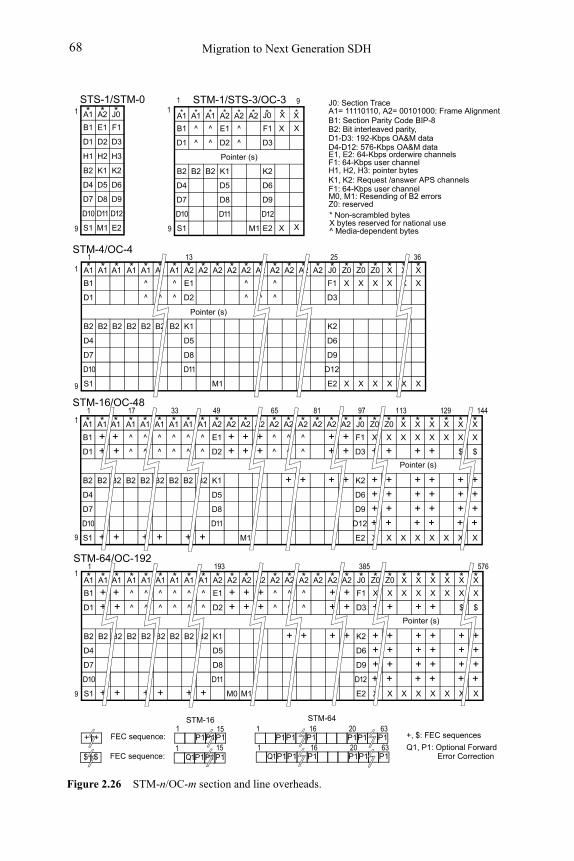
Migration to Next Generation SDH68
Figure 2.26 STM-n/OC-m section and line overheads.
* Non-scrambled bytesX bytes reserved for national use^ Media-dependent bytes
B1 ^ ^ E1 ^
*A1 *A1 *A1 *A2 *A2 *A2 * *
F1
D1 ^ ^ D2 ^ D3
Pointer (s)
B2 B2 B2 K1 K2
D4 D5 D6
D7 D8 D9
S1 E2
D10 D11 D12
M1
STM-1/STS-3/OC-3
X
X
X
X
X
J0 *
X
B1 E1
*A1 *A2 *
F1
D1 D2 D3
B2 K1 K2
D4 D5 D6
D7 D8 D9
S1 E2
D10 D11 D12
STS-1/STM-0J0
M1
B1
*A1 *A1 *
D1
B2 B2 B2
D4
D7
S1
D10
A1 *A1
B2
^
*A1
^
B2
^
*A1
^
B2
E1
*A2
D2
K1
D5
D8
D11
*A2 *A2
M1
*A2
^
*A2
^
^
*A2
^
*A2 *A2
F1
*J0
D3
K2
D6
D9
E2
D12
X
*Z0
X
X
*Z0
X
X
*Z0
X
X
*X
X
X
*X
X
^
*A1
^
B2
^
*A2
^
*A2
X
*X
X
Pointer (s)
1 13 25 36 STM-4/OC-4
B1 +
*A1 *A1 *
+
D1 + +
B2 B2 B2
D4
D7
S1 +D10
A1
+
^
*A1
^
B2
^
*A1
^
B2
+
E1
*A2
D2
K1
D5
D8
D11
+
*A2
++
*A2
+
M1
+
*A2
+^
*A2
^
^
*A2
^
+
*A2
+
*A2
+
+
F1
*J0
D3
K2
D6
D9
E2
D12
X
*Z0
+
+++
X
+
X
*Z0
+
+++
X
+
X
*X
X
X
*X
+
+++
X
+
X
*X
+
+++
X
+
^
*A1
^
B2
+
^
*A2
^
+
+
*A2
+
+
X
*X
$
+++
X
+
Pointer (s)
1 49 97 144 STM-16/OC-48
D1-D3: 192-Kbps OA&M dataD4-D12: 576-Kbps OA&M dataE1, E2: 64-Kbps orderwire channels
M0, M1: Resending of B2 errors
F1: 64-Kbps user channelH1, H2, H3: pointer bytes
Z0: reserved
K1, K2: Request /answer APS channelsF1: 64-Kbps user channel
A1= 11110110, A2= 00101000: Frame AlignmentB1: Section Parity Code BIP-8B2: Bit interleaved parity,
J0: Section Trace
17
^
*A1
^
B2
^
*A1
^
B2
+
^
*A1
^
B2
+
33 65 81 113
X
*X
X
129
X
*X
$
+++
X
+
B1 +
*A1 *A1 *
+
D1 + +
B2 B2 B2
D4
D7
S1 +D10
A1
+
^
*A1
^
B2
^
*A1
^
B2
+
E1
*A2
D2
K1
D5
D8
D11
+
*A2
+
M0
+
*A2
+
M1
+
*A2
+^
*A2
^
^
*A2
^
+
*A2
+
*A2
+
+
F1
*J0
D3
K2
D6
D9
E2
D12
X
*Z0
+
+++
X
+
X
*Z0
+
+++
X
+
X
*X
X
X
*X
+
+++
X
+
X
*X
+
+++
X
+
^
*A1
^
B2
+
^
*A2
^
+
+
*A2
+
+
X
*X
$
+++
X
+
Pointer (s)
1 193 385 576 STM-64/OC-192
^
*A1
^
B2
^
*A1
^
B2
+
^
*A1
^
B2
+
X
*X
X
X
*X
$
+++
X
+
+ + P1151
FEC sequence:
$ $ Q1P1P1P1151
FEC sequence:
P1P1 P1161
P1P1 P16320
P1P1
Q1P1P1 P1161
P1P1 P16320
STM-16 STM-64
1 9
99
11
9
1
9
1
9
1
+, $: FEC sequences
Q1, P1: Optional Forward Error Correction
H1 H2 H3
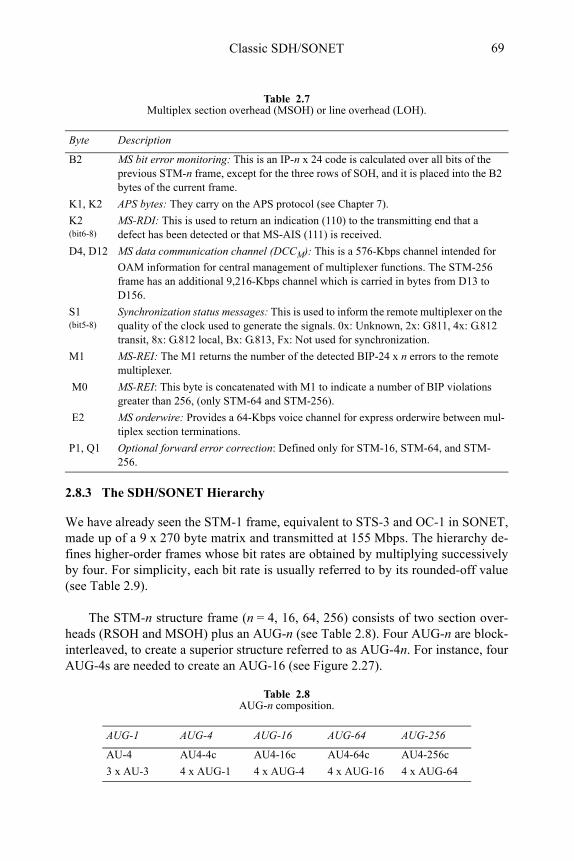
Classic SDH/SONET 69
2.8.3 The SDH/SONET Hierarchy
We have already seen the STM-1 frame, equivalent to STS-3 and OC-1 in SONET, made up of a 9 x 270 byte matrix and transmitted at 155 Mbps. The hierarchy de-fines higher-order frames whose bit rates are obtained by multiplying successively by four. For simplicity, each bit rate is usually referred to by its rounded-off value (see Table 2.9).
The STM-n structure frame (n = 4, 16, 64, 256) consists of two section over-heads (RSOH and MSOH) plus an AUG-n (see Table 2.8). Four AUG-n are block-interleaved, to create a superior structure referred to as AUG-4n. For instance, four AUG-4s are needed to create an AUG-16 (see Figure 2.27).
Table 2.7Multiplex section overhead (MSOH) or line overhead (LOH).
Byte Description
B2 MS bit error monitoring: This is an IP-n x 24 code is calculated over all bits of the previous STM-n frame, except for the three rows of SOH, and it is placed into the B2 bytes of the current frame.
K1, K2 APS bytes: They carry on the APS protocol (see Chapter 7).
K2 (bit6-8)
MS-RDI: This is used to return an indication (110) to the transmitting end that a defect has been detected or that MS-AIS (111) is received.
D4, D12 MS data communication channel (DCCM): This is a 576-Kbps channel intended for
OAM information for central management of multiplexer functions. The STM-256 frame has an additional 9,216-Kbps channel which is carried in bytes from D13 to D156.
S1 (bit5-8)
Synchronization status messages: This is used to inform the remote multiplexer on the quality of the clock used to generate the signals. 0x: Unknown, 2x: G811, 4x: G.812 transit, 8x: G.812 local, Bx: G.813, Fx: Not used for synchronization.
M1 MS-REI: The M1 returns the number of the detected BIP-24 x n errors to the remote multiplexer.
M0 MS-REI: This byte is concatenated with M1 to indicate a number of BIP violations greater than 256, (only STM-64 and STM-256).
E2 MS orderwire: Provides a 64-Kbps voice channel for express orderwire between mul-tiplex section terminations.
P1, Q1 Optional forward error correction: Defined only for STM-16, STM-64, and STM-256.
Table 2.8AUG-n composition.
AUG-1 AUG-4 AUG-16 AUG-64 AUG-256
AU-4 AU4-4c AU4-16c AU4-64c AU4-256c
3 x AU-3 4 x AUG-1 4 x AUG-4 4 x AUG-16 4 x AUG-64
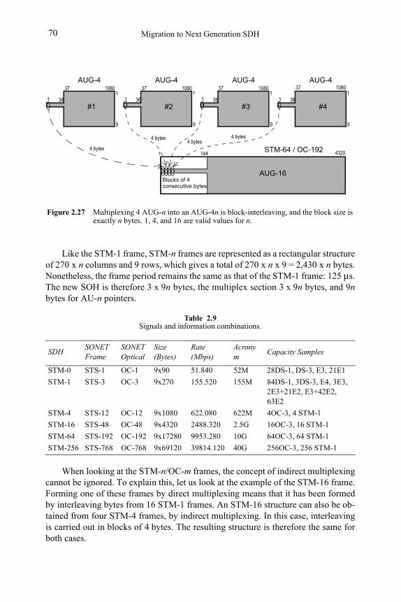
Migration to Next Generation SDH70
Like the STM-1 frame, STM-n frames are represented as a rectangular structure of 270 x n columns and 9 rows, which gives a total of 270 x n x 9 = 2,430 x n bytes. Nonetheless, the frame period remains the same as that of the STM-1 frame: 125 μs. The new SOH is therefore 3 x 9n bytes, the multiplex section 3 x 9n bytes, and 9nbytes for AU-n pointers.
When looking at the STM-n/OC-m frames, the concept of indirect multiplexing cannot be ignored. To explain this, let us look at the example of the STM-16 frame. Forming one of these frames by direct multiplexing means that it has been formed by interleaving bytes from 16 STM-1 frames. An STM-16 structure can also be ob-tained from four STM-4 frames, by indirect multiplexing. In this case, interleaving is carried out in blocks of 4 bytes. The resulting structure is therefore the same for both cases.
Table 2.9Signals and information combinations.
SDHSONET Frame
SONET Optical
Size (Bytes)
Rate (Mbps)
Acronym
Capacity Samples
STM-0 STS-1 OC-1 9x90 51.840 52M 28DS-1, DS-3, E3, 21E1
STM-1 STS-3 OC-3 9x270 155.520 155M 84DS-1, 3DS-3, E4, 3E3, 2E3+21E2, E3+42E2, 63E2
STM-4 STS-12 OC-12 9x1080 622.080 622M 4OC-3, 4 STM-1
STM-16 STS-48 OC-48 9x4320 2488.320 2.5G 16OC-3, 16 STM-1
STM-64 STS-192 OC-192 9x17280 9953.280 10G 64OC-3, 64 STM-1
STM-256 STS-768 OC-768 9x69120 39814.120 40G 256OC-3, 256 STM-1
Figure 2.27 Multiplexing 4 AUG-n into an AUG-4n is block-interleaving, and the block size is exactly n bytes. 1, 4, and 16 are valid values for n.
#11 36
1
9
AUG-16
4 bytes STM-64 / OC-192
#21 36
AUG-4
1
9
#31 36
AUG-4
1
9
#41 36
AUG-4
1
9
AUG-4
4320
108037 108037 108037 108037
1 144
Blocks of 4consecutive bytes
4 bytes4 bytes
4 bytes
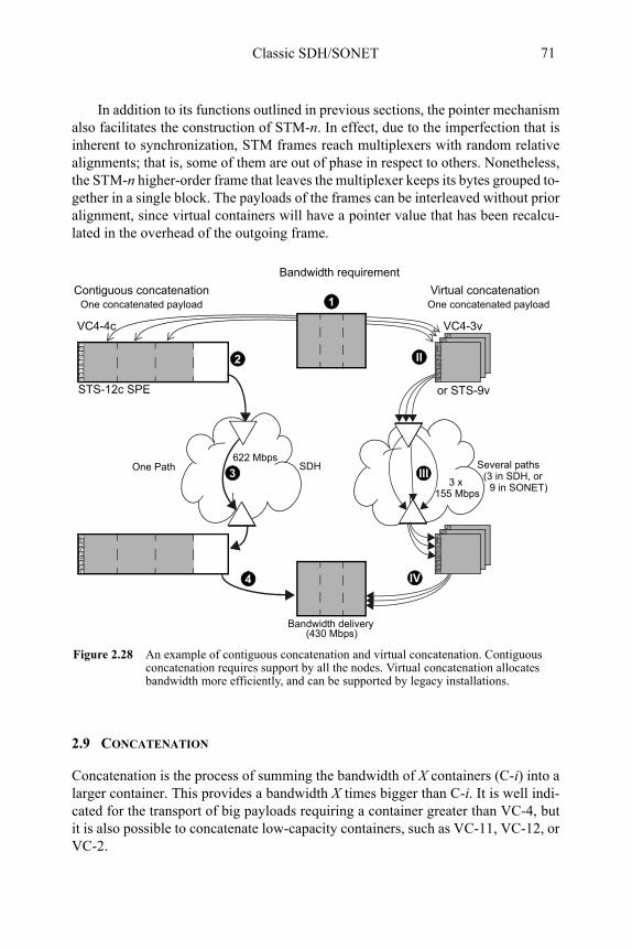
Classic SDH/SONET 71
In addition to its functions outlined in previous sections, the pointer mechanism also facilitates the construction of STM-n. In effect, due to the imperfection that is inherent to synchronization, STM frames reach multiplexers with random relative alignments; that is, some of them are out of phase in respect to others. Nonetheless, the STM-n higher-order frame that leaves the multiplexer keeps its bytes grouped to-gether in a single block. The payloads of the frames can be interleaved without prior alignment, since virtual containers will have a pointer value that has been recalcu-lated in the overhead of the outgoing frame.
2.9 CONCATENATION
Concatenation is the process of summing the bandwidth of X containers (C-i) into a larger container. This provides a bandwidth X times bigger than C-i. It is well indi-cated for the transport of big payloads requiring a container greater than VC-4, but it is also possible to concatenate low-capacity containers, such as VC-11, VC-12, or VC-2.
G1F2H4
J1B3C2
F3K3N1
G1F2H4
J1B3C2
F3K3N1
Figure 2.28 An example of contiguous concatenation and virtual concatenation. Contiguous concatenation requires support by all the nodes. Virtual concatenation allocates bandwidth more efficiently, and can be supported by legacy installations.
Bandwidth requirement
G1F2H4
J1B3C2
F3K3N1
SDH
G1F2H4
J1B3C2
F3K3N1
One concatenated payload
G1F2H4
J1B3C2
F3K3N1
G1F2H4
J1B3C2
F3K3N1
G1F2H4
J1B3C2
F3K3N1
G1F2H4
J1B3C2
F3K3N1
VC4-4c VC4-3v
Bandwidth delivery
One Path Several paths
(430 Mbps)
2
1
3 III
4
II
IV
622 Mbps
3 x155 Mbps
Contiguous concatenation Virtual concatenation
STS-12c SPE or STS-9v
(3 in SDH, or9 in SONET)
One concatenated payload
Migration to Next Generation SDH72
There are two concatenation methods (see Figure 2.28):
1. Contiguous concatenation: which creates big containers that cannot split into smaller pieces during transmission. For this, each NE must have a concatena-tion functionality (see Section 3.5.1).
2. Virtual concatenation: which transports the individual VCs and aggregates them at the end point of the transmission path. For this, concatenation function-ality is only needed at the path termination equipment (see Section 3.5.2).
2.10 MAINTENANCE
SDH and SONET transmission systems are robust and reliable; however they are vulnerable to several effects that may cause malfunction. These effects can be clas-sified as follows:
• Natural causes: This include thermal noise, always present in regeneration sys-tems; solar radiation; humidity and Raleigh fading2 in radio systems; hardware aging; degraded lasers; degradation of electric connections; and electrostatic discharge.
• A network design pitfall: Bit errors due to bad synchronization in SDH. Timing loops may collapse a transmission network partially, or even completely.
• Human intervention: This includes fiber cuts, electrostatic discharges, power failure, and topology modifications.
All these may produce changes in performance, and eventually collapse transmis-sion services.
2.10.1 SDH/SONET Events
SDH/SONET events are classified as anomalies, defects, damage, failures, and alarms depending on how they affect the service:
• Anomaly: This is the smallest disagreement that can be observed between mea-sured and expected characteristics. It could for instance be a bit error. If a sin-gle anomaly occurs, the service will not be interrupted. Anomalies are used to monitor performance and detect defects (see Section 2.11).
2. Raleigh fading is the phenomenon in which the field detected at the receiver is the sum of many random contributions of different phases and directions, due to multi-path effects.
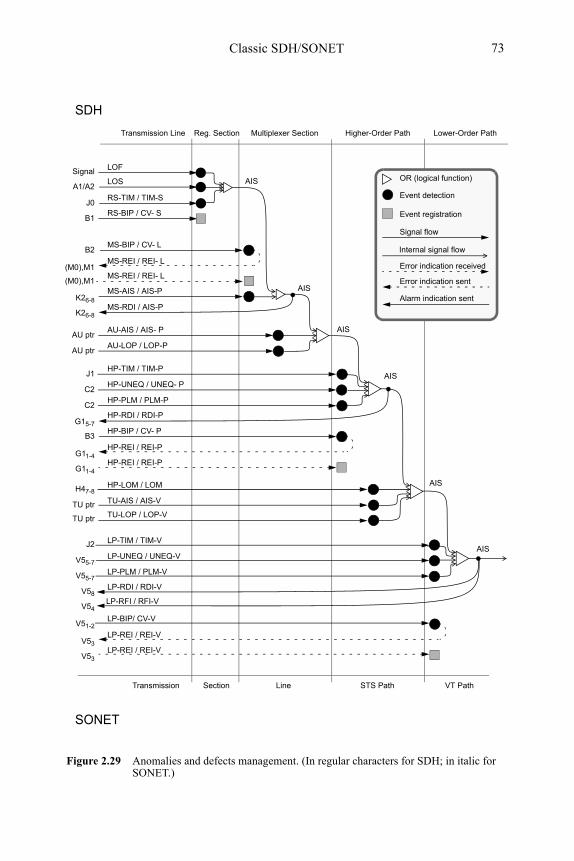
Classic SDH/SONET 73
Figure 2.29 Anomalies and defects management. (In regular characters for SDH; in italic for SONET.)
Reg. Section Multiplexer Section Higher-Order Path Lower-Order Path
LOF
LOSA1/A2
RS-TIM / TIM-SJ0
RS-BIP / CV- SB1
MS-BIP / CV- LB2
(M0),M1MS-REI / REI- L
MS-AIS / AIS-PK26-8
MS-REI / REI- L(M0),M1
AU-AIS / AIS- PAU ptr
MS-RDI / AIS-PK26-8
AU-LOP / LOP-PAU ptr
HP-UNEQ / UNEQ- PC2
HP-PLM / PLM-PC2
HP-BIP / CV- PB3
G11-4HP-REI / REI-P
HP-RDI / RDI-PG15-7
HP-REI / REI-PG11-4
HP-LOM / LOMH47-8
TU-AIS / AIS-VTU ptr
TU ptr TU-LOP / LOP-V
J2 LP-TIM / TIM-V
V55-7LP-PLM / PLM-V
LP-BIP/ CV-VV51-2
V53LP-REI / REI-V
LP-REI / REI-VV53
V58LP-RDI / RDI-V
Transmission Line
HP-TIM / TIM-PJ1
V55-7LP-UNEQ / UNEQ-V
Event detection
Signal flow
Error indication received
Error indication sent
Alarm indication sent
OR (logical function)
Event registration
SDH
SONET
Section Line STS Path VT PathTransmission
AIS
AIS
AIS
AIS
AIS
AIS
Signal
LP-RFI / RFI-VV54
Internal signal flow
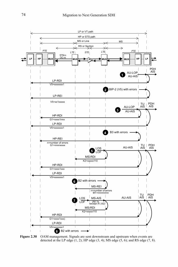
Migration to Next Generation SDH74
Figure 2.30 OAM management. Signals are sent downstream and upstream when events are detected at the LP edge (1, 2); HP edge (3, 4); MS edge (5, 6); and RS edge (7, 8).
PDHAU-LOPAU-AIS
LP-RDIV5=xxxxxxx1
LPHPMUXHPLP MUX
PTE PTE
MUX
STM-nOC-m
MUX R
LP or VT path
HP or STS path
MS or Line
RS or Section
BIP-2 (V5) with errors
LP-REI
V5=xx1xxxxx
AU-LOP
AU-AIS
HP-RDIG1=xxxx1nnx
B3 with errors
HP-REIn=number of errors
G1=nnnnxxxx
AIS
TUAIS
PDHAIS
LP-RDIV5=xxxxxxx1
AU-AIS
HP-RDIG1=xxxx1xxx
B2 with errors
MS-RDIK2=xxxxx110
TUAIS
LP-RDIV5=xxxxxxx1
PDHAISLOS
LOF
MS-REIn=number of errors
M1=nnnnnnnn
HP-RDIG1=xxxx1xxx)
B2 with errors
MS-RDIK2=xxxxx110
LP-RDIV5=xxxxxxx1
LOSLOF
AU-AISTUAIS
PDHAISMS-AIS
(All 1sexcept A1,A2)
1
2
4
3
5
6
7
8
MS
LTELTE STE
Classic SDH/SONET 75
Defect: A defect level is reached when the density of anomalies is high enough to interrupt a function. Defects are used as input for performance monitoring, to con-trol consequent actions, and to determine fault causes.
• Damage or fault: This is produced when a function cannot finish a requested action. This situation does not comprise incapacities caused by preventive maintenance.
• Failure: Here, the fault cause has persisted long enough so that the ability of an item to perform a required function may be terminated. Protection mechanisms can now be activated (see Section 2.13).
• Alarm: This is a human-observable indication that draws attention to a failure (detected fault), usually giving an indication of the depth of the damage. For example, a light emitting diode (LED), a siren, or an e-mail.
• Indication: Here events are notified upstream to the peer layer for performance monitoring and eventually to request an action or a human intervention that can fix the situation (see Figure 2.29).
Errors reflect anomalies, and alarms show defects. Terminology here is often used in a confusing way, in the sense that people may talk about errors but actually refer to anomalies, or use the word, “alarm” to refer to a defect.
In order to support a single-end operation the defect status and the number of detected bit errors are sent back to the far-end termination by means of indications such an RDI, REI, or RFI (see Figures 2.31 and 2.32).
2.10.2 Monitoring Events
SDH frames contain a lot of overhead information to monitor and manage events (see Table 2.16). When events are detected, overhead channels are used to notify peer layers to run network protection procedures or evaluate performance. Messag-es are also sent to higher layers to indicate the local detection of a service affecting fault to the far-end terminations.
Defects trigger a sequence of upstream messages using G1 and V2 bytes. Down-stream AIS signals are sent to indicate service unavailability. When defects are de-tected, upstream indications are sent to register and troubleshoot causes.
2.10.3 Event Tables
Tables 2.12-2.16 summarize events and indications associated with each SDH lay-er. Testing events have also been included. .
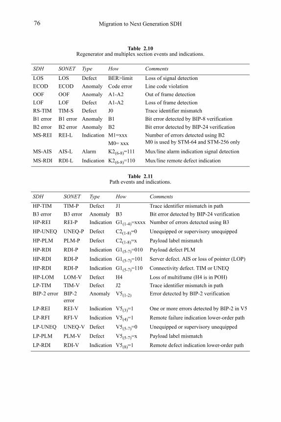
Migration to Next Generation SDH76
Table 2.10Regenerator and multiplex section events and indications.
SDH SONET Type How Comments
LOS LOS Defect BER>limit Loss of signal detection
ECOD ECOD Anomaly Code error Line code violation
OOF OOF Anomaly A1-A2 Out of frame detection
LOF LOF Defect A1-A2 Loss of frame detection
RS-TIM TIM-S Defect J0 Trace identifier mismatch
B1 error B1 error Anomaly B1 Bit error detected by BIP-8 verification
B2 error B2 error Anomaly B2 Bit error detected by BIP-24 verification
MS-REI REI-L Indication M1=xxx
M0= xxx
Number of errors detected using B2 M0 is used by STM-64 and STM-256 only
MS-AIS AIS-L Alarm K2(6-8)=111 Mux/line alarm indication signal detection
MS-RDI RDI-L Indication K2(6-8)=110 Mux/line remote defect indication
Table 2.11Path events and indications.
SDH SONET Type How Comments
HP-TIM TIM-P Defect J1 Trace identifier mismatch in path
B3 error B3 error Anomaly B3 Bit error detected by BIP-24 verification
HP-REI REI-P Indication G1(1-4)=xxxx Number of errors detected using B3
HP-UNEQ UNEQ-P Defect C2(1-8)=0 Unequipped or supervisory unequipped
HP-PLM PLM-P Defect C2(1-8)=x Payload label mismatch
HP-RDI RDI-P Indication G1(5-7)=010 Payload defect PLM
HP-RDI RDI-P Indication G1(5-7)=101 Server defect. AIS or loss of pointer (LOP)
HP-RDI RDI-P Indication G1(5-7)=110 Connectivity defect. TIM or UNEQ
HP-LOM LOM-V Defect H4 Loss of multiframe (H4 is in POH)
LP-TIM TIM-V Defect J2 Trace identifier mismatch in path
BIP-2 error BIP-2 error
Anomaly V5(1-2) Error detected by BIP-2 verification
LP-REI REI-V Indication V5(3)=1 One or more errors detected by BIP-2 in V5
LP-RFI RFI-V Indication V5(4)=1 Remote failure indication lower-order path
LP-UNEQ UNEQ-V Defect V5(5-7)=0 Unequipped or supervisory unequipped
LP-PLM PLM-V Defect V5(5-7)=x Payload label mismatch
LP-RDI RDI-V Indication V5(8)=1 Remote defect indication lower-order path
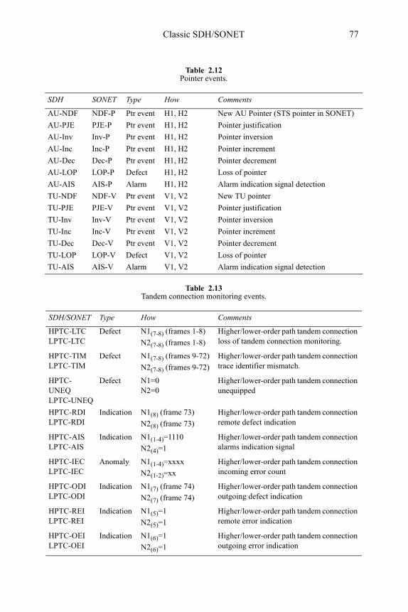
Classic SDH/SONET 77
Table 2.12Pointer events.
SDH SONET Type How Comments
AU-NDF NDF-P Ptr event H1, H2 New AU Pointer (STS pointer in SONET)
AU-PJE PJE-P Ptr event H1, H2 Pointer justification
AU-Inv Inv-P Ptr event H1, H2 Pointer inversion
AU-Inc Inc-P Ptr event H1, H2 Pointer increment
AU-Dec Dec-P Ptr event H1, H2 Pointer decrement
AU-LOP LOP-P Defect H1, H2 Loss of pointer
AU-AIS AIS-P Alarm H1, H2 Alarm indication signal detection
TU-NDF NDF-V Ptr event V1, V2 New TU pointer
TU-PJE PJE-V Ptr event V1, V2 Pointer justification
TU-Inv Inv-V Ptr event V1, V2 Pointer inversion
TU-Inc Inc-V Ptr event V1, V2 Pointer increment
TU-Dec Dec-V Ptr event V1, V2 Pointer decrement
TU-LOP LOP-V Defect V1, V2 Loss of pointer
TU-AIS AIS-V Alarm V1, V2 Alarm indication signal detection
Table 2.13Tandem connection monitoring events.
SDH/SONET Type How Comments
HPTC-LTC LPTC-LTC
Defect N1(7-8) (frames 1-8) N2(7-8) (frames 1-8)
Higher/lower-order path tandem connection loss of tandem connection monitoring.
HPTC-TIM LPTC-TIM
Defect N1(7-8) (frames 9-72) N2(7-8) (frames 9-72)
Higher/lower-order path tandem connection trace identifier mismatch.
HPTC-UNEQ LPTC-UNEQ
Defect N1=0 N2=0
Higher/lower-order path tandem connection unequipped
HPTC-RDI LPTC-RDI
Indication N1(8) (frame 73) N2(8) (frame 73)
Higher/lower-order path tandem connection remote defect indication
HPTC-AIS LPTC-AIS
Indication N1(1-4)=1110 N2(4)=1
Higher/lower-order path tandem connection alarms indication signal
HPTC-IEC LPTC-IEC
Anomaly N1(1-4)=xxxx N2(1-2)=xx
Higher/lower-order path tandem connection incoming error count
HPTC-ODI LPTC-ODI
Indication N1(7) (frame 74) N2(7) (frame 74)
Higher/lower-order path tandem connection outgoing defect indication
HPTC-REI LPTC-REI
Indication N1(5)=1 N2(5)=1
Higher/lower-order path tandem connection remote error indication
HPTC-OEI LPTC-OEI
Indication N1(6)=1 N2(6)=1
Higher/lower-order path tandem connection outgoing error indication
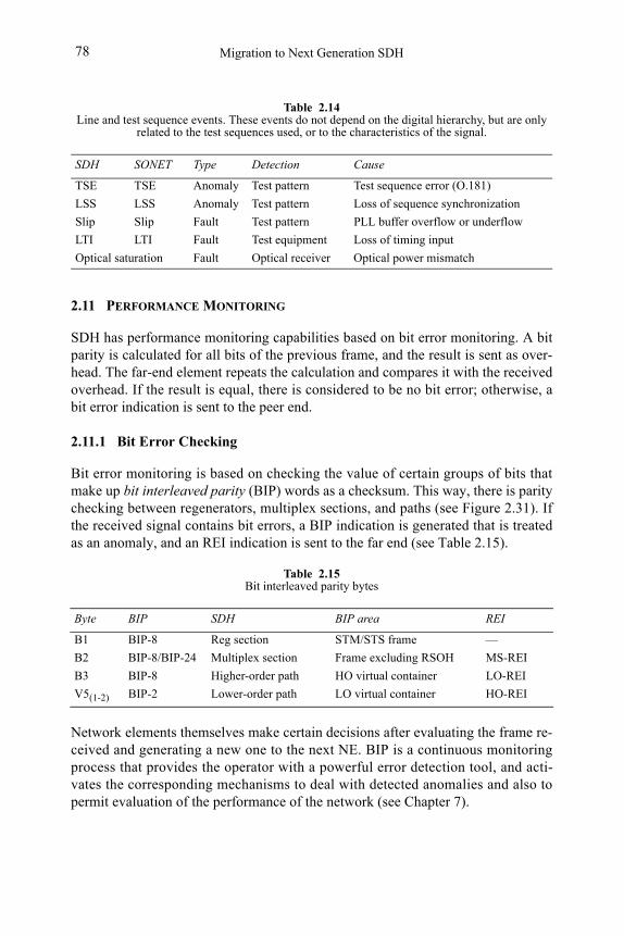
Migration to Next Generation SDH78
2.11 PERFORMANCE MONITORING
SDH has performance monitoring capabilities based on bit error monitoring. A bit parity is calculated for all bits of the previous frame, and the result is sent as over-head. The far-end element repeats the calculation and compares it with the received overhead. If the result is equal, there is considered to be no bit error; otherwise, a bit error indication is sent to the peer end.
2.11.1 Bit Error Checking
Bit error monitoring is based on checking the value of certain groups of bits that make up bit interleaved parity (BIP) words as a checksum. This way, there is parity checking between regenerators, multiplex sections, and paths (see Figure 2.31). If the received signal contains bit errors, a BIP indication is generated that is treated as an anomaly, and an REI indication is sent to the far end (see Table 2.15).
Network elements themselves make certain decisions after evaluating the frame re-ceived and generating a new one to the next NE. BIP is a continuous monitoring process that provides the operator with a powerful error detection tool, and acti-vates the corresponding mechanisms to deal with detected anomalies and also to permit evaluation of the performance of the network (see Chapter 7).
Table 2.14Line and test sequence events. These events do not depend on the digital hierarchy, but are only
related to the test sequences used, or to the characteristics of the signal.
SDH SONET Type Detection Cause
TSE TSE Anomaly Test pattern Test sequence error (O.181)
LSS LSS Anomaly Test pattern Loss of sequence synchronization
Slip Slip Fault Test pattern PLL buffer overflow or underflow
LTI LTI Fault Test equipment Loss of timing input
Optical saturation Fault Optical receiver Optical power mismatch
Table 2.15Bit interleaved parity bytes
Byte BIP SDH BIP area REI
B1 BIP-8 Reg section STM/STS frame —
B2 BIP-8/BIP-24 Multiplex section Frame excluding RSOH MS-REI
B3 BIP-8 Higher-order path HO virtual container LO-REI
V5(1-2) BIP-2 Lower-order path LO virtual container HO-REI
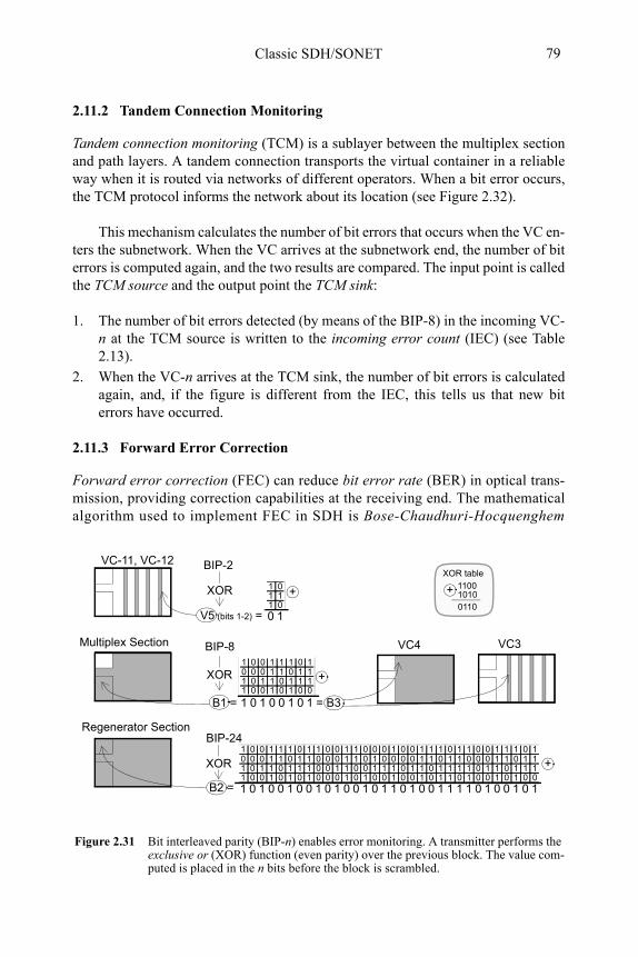
Classic SDH/SONET 79
2.11.2 Tandem Connection Monitoring
Tandem connection monitoring (TCM) is a sublayer between the multiplex section and path layers. A tandem connection transports the virtual container in a reliable way when it is routed via networks of different operators. When a bit error occurs, the TCM protocol informs the network about its location (see Figure 2.32).
This mechanism calculates the number of bit errors that occurs when the VC en-ters the subnetwork. When the VC arrives at the subnetwork end, the number of bit errors is computed again, and the two results are compared. The input point is called the TCM source and the output point the TCM sink:
1. The number of bit errors detected (by means of the BIP-8) in the incoming VC-n at the TCM source is written to the incoming error count (IEC) (see Table 2.13).
2. When the VC-n arrives at the TCM sink, the number of bit errors is calculated again, and, if the figure is different from the IEC, this tells us that new bit errors have occurred.
2.11.3 Forward Error Correction
Forward error correction (FEC) can reduce bit error rate (BER) in optical trans-mission, providing correction capabilities at the receiving end. The mathematical algorithm used to implement FEC in SDH is Bose-Chaudhuri-Hocquenghem
Figure 2.31 Bit interleaved parity (BIP-n) enables error monitoring. A transmitter performs the exclusive or (XOR) function (even parity) over the previous block. The value com-puted is placed in the n bits before the block is scrambled.
1 0 0 1 1 1 0 10 0 0 1 1 0 1 11 0 1 1 0 1 1 11 0 0 1 0 1 0 0
10100101
XOR
B1 =
1 01 11 0
10
XOR
V5 (bits 1-2) =
BIP-2
Multiplex Section
VC-11, VC-12
1 0 0 1 1 1 0 10 0 0 1 1 0 1 11 0 1 1 0 1 1 11 0 0 1 0 1 0 1
00100101
XOR
B2 =
1 0 0 1 1 0 0 00 0 0 1 1 0 1 00 0 1 1 0 0 1 10 0 0 1 0 1 0 0
10100101
1 0 0 1 1 1 0 10 0 0 1 1 0 1 11 0 1 1 0 1 1 11 0 0 1 0 1 1 0
11100101
1 0 0 1 1 1 0 10 0 0 1 1 0 1 11 0 1 1 0 1 1 11 0 0 1 0 1 0 0
10100101
VC4
= B3
Regenerator Section
BIP-8 VC3
BIP-24
110010100110
XOR table
++
+
+
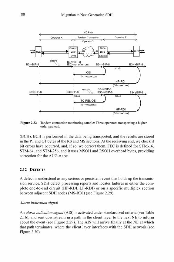
Migration to Next Generation SDH80
(BCH). BCH is performed in the data being transported, and the results are stored in the P1 and Q1 bytes of the RS and MS sections. At the receiving end, we check if bit errors have occurred, and, if so, we correct them. FEC is defined for STM-16, STM-64, and STM-256, and it uses MSOH and RSOH overhead bytes, providing correction for the AUG-n area.
2.12 DEFECTS
A defect is understood as any serious or persistent event that holds up the transmis-sion service. SDH defect processing reports and locates failures in either the com-plete end-to-end circuit (HP-RDI, LP-RDI) or on a specific multiplex section between adjacent SDH nodes (MS-RDI) (see Figure 2.29).
Alarm indication signal
An alarm indication signal (AIS) is activated under standardized criteria (see Table 2.16), and sent downstream in a path in the client layer to the next NE to inform about the event (see Figure 2.29). The AIS will arrive finally at the NE at which that path terminates, where the client layer interfaces with the SDH network (see Figure 2.30).
Figure 2.32 Tandem connection monitoring sample: Three operators transporting a higher-order payload.
OEI
MUX
VC Path
Tandem Connection
HP-RDI(G1=xxxx1xxx)
MUX
Operator X Operator Z
Source
Sync
B3:=BIP-8 errors
B3=BIP-8
IEC=no. of errors
(N1=xxxxx1xx)
N1=0
B3<>BIP-8
MUX
Sync
Source
MUX
B3<>BIP-8
Operator Y
TC-REI, OEI
HP-RDI
(N1=xxxx11xx)
N1=0
B3<>BIP-8B3<>BIP-8errorsIEC<>BIP-8B3:=BIP-8
(G1=xxxx1xxx)
B3<>BIP-8
N1=0
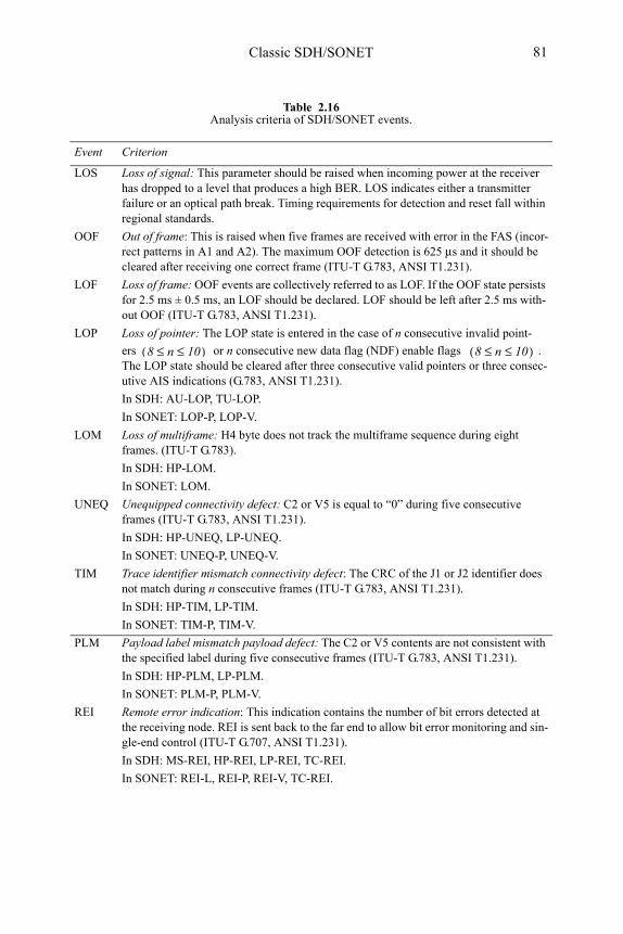
Classic SDH/SONET 81
Table 2.16Analysis criteria of SDH/SONET events.
Event Criterion
LOS Loss of signal: This parameter should be raised when incoming power at the receiver has dropped to a level that produces a high BER. LOS indicates either a transmitter failure or an optical path break. Timing requirements for detection and reset fall within regional standards.
OOF Out of frame: This is raised when five frames are received with error in the FAS (incor-rect patterns in A1 and A2). The maximum OOF detection is 625 μs and it should be cleared after receiving one correct frame (ITU-T G.783, ANSI T1.231).
LOF Loss of frame: OOF events are collectively referred to as LOF. If the OOF state persists for 2.5 ms ± 0.5 ms, an LOF should be declared. LOF should be left after 2.5 ms with-out OOF (ITU-T G.783, ANSI T1.231).
LOP Loss of pointer: The LOP state is entered in the case of n consecutive invalid point-
ers or n consecutive new data flag (NDF) enable flags . The LOP state should be cleared after three consecutive valid pointers or three consec-utive AIS indications (G.783, ANSI T1.231).
In SDH: AU-LOP, TU-LOP.
In SONET: LOP-P, LOP-V.
LOM Loss of multiframe: H4 byte does not track the multiframe sequence during eight frames. (ITU-T G.783).
In SDH: HP-LOM.
In SONET: LOM.
UNEQ Unequipped connectivity defect: C2 or V5 is equal to “0” during five consecutive frames (ITU-T G.783, ANSI T1.231).
In SDH: HP-UNEQ, LP-UNEQ.
In SONET: UNEQ-P, UNEQ-V.
TIM Trace identifier mismatch connectivity defect: The CRC of the J1 or J2 identifier does not match during n consecutive frames (ITU-T G.783, ANSI T1.231).
In SDH: HP-TIM, LP-TIM.
In SONET: TIM-P, TIM-V.
PLM Payload label mismatch payload defect: The C2 or V5 contents are not consistent with the specified label during five consecutive frames (ITU-T G.783, ANSI T1.231).
In SDH: HP-PLM, LP-PLM.
In SONET: PLM-P, PLM-V.
REI Remote error indication: This indication contains the number of bit errors detected at the receiving node. REI is sent back to the far end to allow bit error monitoring and sin-gle-end control (ITU-T G.707, ANSI T1.231).
In SDH: MS-REI, HP-REI, LP-REI, TC-REI.
In SONET: REI-L, REI-P, REI-V, TC-REI.
8 n 10≤ ≤( ) 8 n 10≤ ≤( )
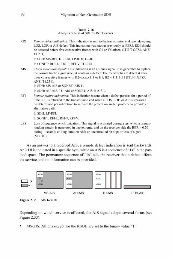
Migration to Next Generation SDH82
As an answer to a received AIS, a remote defect indication is sent backwards. An RDI is indicated in a specific byte, while an AIS is a sequence of “1s” in the pay-load space. The permanent sequence of “1s” tells the receiver that a defect affects the service, and no information can be provided.
Depending on which service is affected, the AIS signal adopts several forms (see Figure 2.33):
• MS-AIS: All bits except for the RSOH are set to the binary value “1.”
RDI Remote defect indication: This indication is sent to the transmission end upon detecting LOS, LOF, or AIS defect. This indication was known previously as FERF. RDI should be detected before five consecutive frames with G1 or V5 arisen. (ITU-T G.783, ANSI T1.231).
In SDH: MS-REI, HP-RDI, LP-RDI, TC-REI.
In SONET: RDI-L, RDI-P, REI-V, TC-REI.
AIS Alarm indication signal: This indication is an all-ones signal. It is generated to replace the normal traffic signal when it contains a defect. The receiver has to detect it after three consecutive frames with K2=xxxxx111 or H1, H2 = 11111111 (ITU-T G.783, ANSI T1.231). In SDH: MS-AIS or SONET: AIS-L.
In SDH: AU-AIS, TU-AIS or SONET: AIS-P, AIS-L.
RFI Remote failure indication: This indication is sent when a defect persists for a period of time. RFI is returned to the transmission end when a LOS, LOF, or AIS surpasses a predetermined period of time to activate the protection switch protocol to provide an alternative path.
In SDH: LP-RFI.
In SONET: RFI-L, RFI-P, RFI-V.
LSS Loss of sequence synchronization: This signal is activated during a test when a pseudo-random pattern is generated in one extreme, and on the receiver side the BER > 0.20 during 1 second; or long duration AIS; or uncontrolled bit slip; or loss of signal (M.2100).
Table 2.16Analysis criteria of SDH/SONET events.
Figure 2.33 AIS formats.
RSOH
MSOH
RSOH
MSOH
K2
PTR PTR
RSOH
MSOH
PTR
: X
= 1
AU-AIS TU-AIS PDH-AIS MS-AIS
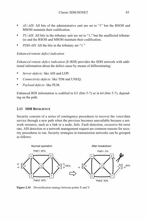
Classic SDH/SONET 83
• AU-AIS: All bits of the administrative unit are set to “1” but the RSOH and MSOH maintain their codification.
• TU-AIS: All bits in the tributary unit are set to “1,” but the unaffected tributar-ies and the RSOH and MSOH maintain their codification.
• PDH-AIS: All the bits in the tributary are “1.”
Enhanced remote defect indication
Enhanced remote defect indication (E-RDI) provides the SDH network with addi-tional information about the defect cause by means of differentiating:
• Server defects: like AIS and LOP;
• Connectivity defects: like TIM and UNEQ;
• Payload defects: like PLM.
Enhanced RDI information is codified in G1 (bits 5-7) or in k4 (bits 5-7), depend-ing on the path.
2.13 SDH RESILIENCE
Security consists of a series of contingency procedures to recover the voice/data service through a new path when the previous becomes unavailable because a net-work resource, such as a link or a node, fails. Fault detection, excessive bit error rate, AIS detection or a network management request are common reasons for secu-rity procedures to run. Security strategies in transmission networks can be grouped as follows:
Figure 2.34 Diversification strategy between points X and Y.
Path1: 60%
Path2: 40%
A B
FE
X YG
A B
FE
X YG
Path1: 0%
Path2: 40%
100% 40%
Normal operation After breakdown
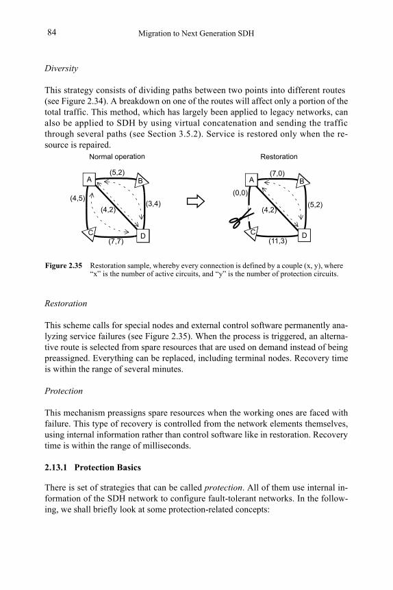
Migration to Next Generation SDH84
Diversity
This strategy consists of dividing paths between two points into different routes (see Figure 2.34). A breakdown on one of the routes will affect only a portion of the total traffic. This method, which has largely been applied to legacy networks, can also be applied to SDH by using virtual concatenation and sending the traffic through several paths (see Section 3.5.2). Service is restored only when the re-source is repaired.
Restoration
This scheme calls for special nodes and external control software permanently ana-lyzing service failures (see Figure 2.35). When the process is triggered, an alterna-tive route is selected from spare resources that are used on demand instead of being preassigned. Everything can be replaced, including terminal nodes. Recovery time is within the range of several minutes.
Protection
This mechanism preassigns spare resources when the working ones are faced with failure. This type of recovery is controlled from the network elements themselves, using internal information rather than control software like in restoration. Recovery time is within the range of milliseconds.
2.13.1 Protection Basics
There is set of strategies that can be called protection. All of them use internal in-formation of the SDH network to configure fault-tolerant networks. In the follow-ing, we shall briefly look at some protection-related concepts:
Figure 2.35 Restoration sample, whereby every connection is defined by a couple (x, y), where “x” is the number of active circuits, and “y” is the number of protection circuits.
(5,2)
(4,2)(3,4)
(7,7)
(4,5)
(7,0)
(4,2)(5,2)
(11,3)
(0,0)
A
D
B
C
A
D
B
C
Normal operation Restoration
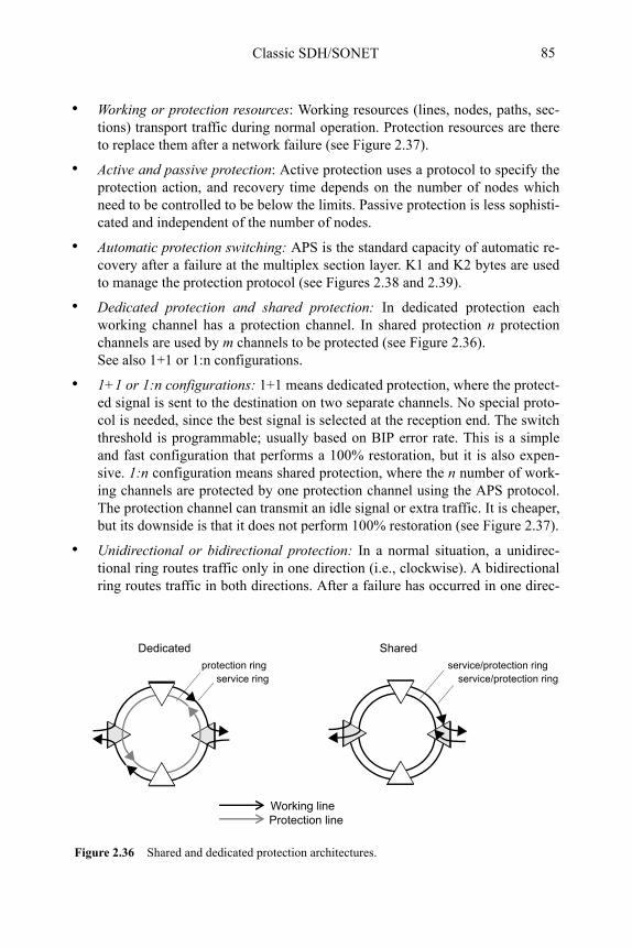
Classic SDH/SONET 85
• Working or protection resources: Working resources (lines, nodes, paths, sec-tions) transport traffic during normal operation. Protection resources are there to replace them after a network failure (see Figure 2.37).
• Active and passive protection: Active protection uses a protocol to specify the protection action, and recovery time depends on the number of nodes which need to be controlled to be below the limits. Passive protection is less sophisti-cated and independent of the number of nodes.
• Automatic protection switching: APS is the standard capacity of automatic re-covery after a failure at the multiplex section layer. K1 and K2 bytes are used to manage the protection protocol (see Figures 2.38 and 2.39).
• Dedicated protection and shared protection: In dedicated protection each working channel has a protection channel. In shared protection n protection channels are used by m channels to be protected (see Figure 2.36). See also 1+1 or 1:n configurations.
• 1+1 or 1:n configurations: 1+1 means dedicated protection, where the protect-ed signal is sent to the destination on two separate channels. No special proto-col is needed, since the best signal is selected at the reception end. The switch threshold is programmable; usually based on BIP error rate. This is a simple and fast configuration that performs a 100% restoration, but it is also expen-sive. 1:n configuration means shared protection, where the n number of work-ing channels are protected by one protection channel using the APS protocol. The protection channel can transmit an idle signal or extra traffic. It is cheaper, but its downside is that it does not perform 100% restoration (see Figure 2.37).
• Unidirectional or bidirectional protection: In a normal situation, a unidirec-tional ring routes traffic only in one direction (i.e., clockwise). A bidirectional ring routes traffic in both directions. After a failure has occurred in one direc-
protection ringservice ring
Figure 2.36 Shared and dedicated protection architectures.
service/protection ringservice/protection ring
Dedicated Shared
Working lineProtection line
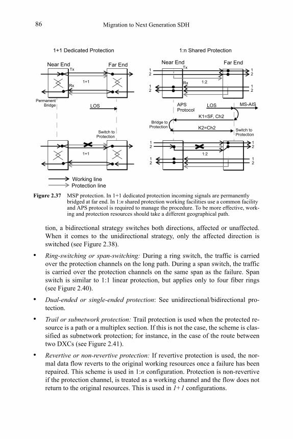
Migration to Next Generation SDH86
tion, a bidirectional strategy switches both directions, affected or unaffected. When it comes to the unidirectional strategy, only the affected direction is switched (see Figure 2.38).
• Ring-switching or span-switching: During a ring switch, the traffic is carried over the protection channels on the long path. During a span switch, the traffic is carried over the protection channels on the same span as the failure. Span switch is similar to 1:1 linear protection, but applies only to four fiber rings (see Figure 2.40).
• Dual-ended or single-ended protection: See unidirectional/bidirectional pro-tection.
• Trail or subnetwork protection: Trail protection is used when the protected re-source is a path or a multiplex section. If this is not the case, the scheme is clas-sified as subnetwork protection; for instance, in the case of the route between two DXCs (see Figure 2.41).
• Revertive or non-revertive protection: If revertive protection is used, the nor-mal data flow reverts to the original working resources once a failure has been repaired. This scheme is used in 1:n configuration. Protection is non-revertiveif the protection channel, is treated as a working channel and the flow does not return to the original resources. This is used in 1+1 configurations.
Figure 2.37 MSP protection. In 1+1 dedicated protection incoming signals are permanently bridged at far end. In 1:n shared protection working facilities use a common facility and APS protocol is required to manage the procedure. To be more effective, work-ing and protection resources should take a different geographical path.
1+1
Near End Far End
1+1 Dedicated Protection 1:n Shared Protection
Near End Far End
1:2
LOS LOS MS-AIS
K1=SF, Ch2
K2=Ch2
1:2
Bridge toProtection
Switch toProtection
1+1
Working lineProtection line
Rx
Tx 12
12
12
12
Rx
Tx
12
12
12
12
PermanentBridge
Switch toProtection
APS Protocol
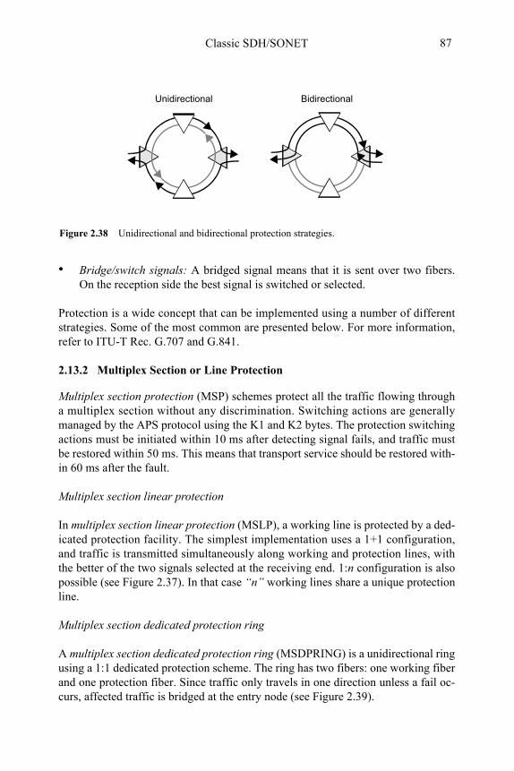
Classic SDH/SONET 87
• Bridge/switch signals: A bridged signal means that it is sent over two fibers. On the reception side the best signal is switched or selected.
Protection is a wide concept that can be implemented using a number of different strategies. Some of the most common are presented below. For more information, refer to ITU-T Rec. G.707 and G.841.
2.13.2 Multiplex Section or Line Protection
Multiplex section protection (MSP) schemes protect all the traffic flowing through a multiplex section without any discrimination. Switching actions are generally managed by the APS protocol using the K1 and K2 bytes. The protection switching actions must be initiated within 10 ms after detecting signal fails, and traffic must be restored within 50 ms. This means that transport service should be restored with-in 60 ms after the fault.
Multiplex section linear protection
In multiplex section linear protection (MSLP), a working line is protected by a ded-icated protection facility. The simplest implementation uses a 1+1 configuration, and traffic is transmitted simultaneously along working and protection lines, with the better of the two signals selected at the receiving end. 1:n configuration is also possible (see Figure 2.37). In that case “n” working lines share a unique protection line.
Multiplex section dedicated protection ring
A multiplex section dedicated protection ring (MSDPRING) is a unidirectional ring using a 1:1 dedicated protection scheme. The ring has two fibers: one working fiber and one protection fiber. Since traffic only travels in one direction unless a fail oc-curs, affected traffic is bridged at the entry node (see Figure 2.39).
Figure 2.38 Unidirectional and bidirectional protection strategies.
Unidirectional Bidirectional
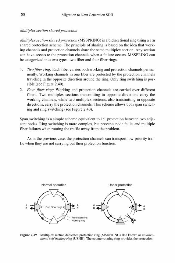
Migration to Next Generation SDH88
Multiplex section shared protection
Multiplex section shared protection (MSSPRING) is a bidirectional ring using a 1:n shared protection scheme. The principle of sharing is based on the idea that work-ing channels and protection channels share the same multiplex section. Any section can have access to the protection channels when a failure occurs. MSSPRING can be categorized into two types: two fiber and four fiber rings.
1. Two fiber ring: Each fiber carries both working and protection channels perma-nently. Working channels in one fiber are protected by the protection channels traveling in the opposite direction around the ring. Only ring switching is pos-sible (see Figure 2.40).
2. Four fiber ring: Working and protection channels are carried over different fibers. Two multiplex sections transmitting in opposite directions carry the working channels, while two multiplex sections, also transmitting in opposite directions, carry the protection channels. This scheme allows both span switch-ing and ring switching (see Figure 2.40).
Span switching is a simple scheme equivalent to 1:1 protection between two adja-cent nodes. Ring switching is more complex, but prevents node faults and multiple fiber failures when routing the traffic away from the problem.
As in the previous case, the protection channels can transport low-priority traf-fic when they are not carrying out their protection function.
Figure 2.39 Multiplex section dedicated protection ring (MSDPRING) also known as unidirec-tional self-healing ring (USHR). The counterrotating ring provides the protection.
One Fiber ringsA A
BB
AB
AB
Protection ringWorking ring
Normal operation Under protection
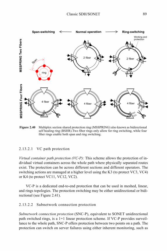
Classic SDH/SONET 89
2.13.2.1 VC path protection
Virtual container path protection (VC-P): This scheme allows the protection of in-dividual virtual containers across the whole path where physically separated routes exist. The protection can be across different sections and different operators. The switching actions are managed at a higher level using the K3 (to protect VC3, VC4) or K4 (to protect VC11, VC12, VC2).
VC-P is a dedicated end-to-end protection that can be used in meshed, linear, and rings topologies. The protection switching may be either unidirectional or bidi-rectional (see Figure 2.41).
2.13.2.2 Subnetwork connection protection
Subnetwork connection protection (SNC-P), equivalent to SONET unidirectional path switched rings, is a 1+1 linear protection scheme. If VC-P provides surveil-lance to the whole path, SNC-P offers protection between two points on a path. The protection can switch on server failures using either inherent monitoring, such as
Figure 2.40 Multiplex section shared protection ring (MSSPRING) also known as bidirectional self healing ring (BSHR).Two fiber rings only allow for ring switching, while four fiber rings enable both span and ring switching.
2 fiber 2 fiber
4 fiber 4 fiber
4 fiber
Span-switching Ring-switchingNormal operation
Working and protection
ring
Span
MS
SP
RIN
G T
wo
Fib
ers
MS
SP
RIN
G F
ou
r F
iber
s
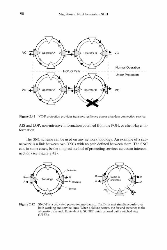
Migration to Next Generation SDH90
AIS and LOP, non-intrusive information obtained from the POH, or client-layer in-formation.
The SNC scheme can be used on any network topology. An example of a sub-network is a link between two DXCs with no path defined between them. The SNC can, in some cases, be the simplest method of protecting services across an intercon-nection (see Figure 2.42).
Figure 2.41 VC-P protection provides transport resilience across a tandem connection service.
VC
HO/LO Path
Operator A Operator B
Operator A Operator B
VC
VC VC
Normal Operation
Under Protection
Protection
Service
ADM
ADM
ADM
Two rings A
B
A
B
A
B
A
B
Figure 2.42 SNC-P is a dedicated protection mechanism. Traffic is sent simultaneously over both working and service lines. When a failure occurs, the far end switches to the alternative channel. Equivalent to SONET unidirectional path switched ring (UPSR).
Switch to protection
Bridging
AIS
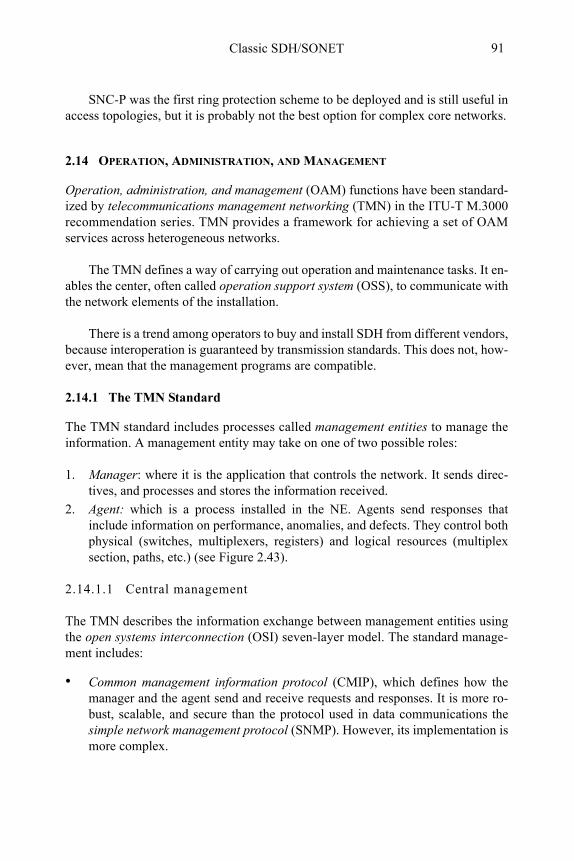
Classic SDH/SONET 91
SNC-P was the first ring protection scheme to be deployed and is still useful in access topologies, but it is probably not the best option for complex core networks.
2.14 OPERATION, ADMINISTRATION, AND MANAGEMENT
Operation, administration, and management (OAM) functions have been standard-ized by telecommunications management networking (TMN) in the ITU-T M.3000 recommendation series. TMN provides a framework for achieving a set of OAM services across heterogeneous networks.
The TMN defines a way of carrying out operation and maintenance tasks. It en-ables the center, often called operation support system (OSS), to communicate with the network elements of the installation.
There is a trend among operators to buy and install SDH from different vendors, because interoperation is guaranteed by transmission standards. This does not, how-ever, mean that the management programs are compatible.
2.14.1 The TMN Standard
The TMN standard includes processes called management entities to manage the information. A management entity may take on one of two possible roles:
1. Manager: where it is the application that controls the network. It sends direc-tives, and processes and stores the information received.
2. Agent: which is a process installed in the NE. Agents send responses that include information on performance, anomalies, and defects. They control both physical (switches, multiplexers, registers) and logical resources (multiplex section, paths, etc.) (see Figure 2.43).
2.14.1.1 Central management
The TMN describes the information exchange between management entities using the open systems interconnection (OSI) seven-layer model. The standard manage-ment includes:
• Common management information protocol (CMIP), which defines how the manager and the agent send and receive requests and responses. It is more ro-bust, scalable, and secure than the protocol used in data communications the simple network management protocol (SNMP). However, its implementation is more complex.
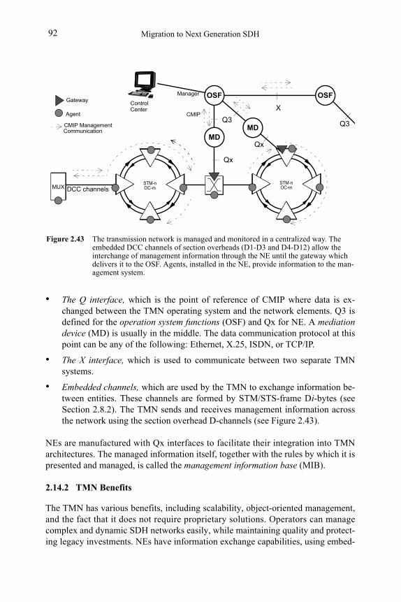
Migration to Next Generation SDH92
• The Q interface, which is the point of reference of CMIP where data is ex-changed between the TMN operating system and the network elements. Q3 is defined for the operation system functions (OSF) and Qx for NE. A mediation device (MD) is usually in the middle. The data communication protocol at this point can be any of the following: Ethernet, X.25, ISDN, or TCP/IP.
• The X interface, which is used to communicate between two separate TMN systems.
• Embedded channels, which are used by the TMN to exchange information be-tween entities. These channels are formed by STM/STS-frame Di-bytes (see Section 2.8.2). The TMN sends and receives management information across the network using the section overhead D-channels (see Figure 2.43).
NEs are manufactured with Qx interfaces to facilitate their integration into TMN architectures. The managed information itself, together with the rules by which it is presented and managed, is called the management information base (MIB).
2.14.2 TMN Benefits
The TMN has various benefits, including scalability, object-oriented management, and the fact that it does not require proprietary solutions. Operators can manage complex and dynamic SDH networks easily, while maintaining quality and protect-ing legacy investments. NEs have information exchange capabilities, using embed-
STM-nOC-m
Figure 2.43 The transmission network is managed and monitored in a centralized way. The embedded DCC channels of section overheads (D1-D3 and D4-D12) allow the interchange of management information through the NE until the gateway which delivers it to the OSF. Agents, installed in the NE, provide information to the man-agement system.
OSFOSF
X
MD
Q3Q3
Qx
MUX
Agent
CMIP ManagementCommunication MD
Qx
GatewayManager
CMIP
STM-nOC-m
ControlCenter
DCC channels
Classic SDH/SONET 93
ded Di channels that enable the OSF to reach to all the points of the network just by using a gateway. This means that the TMN does not need to link all the nodes, just one or a couple of gateways is enough to reach any agent installed in any NE.
The information gathered is the base on which to elaborate performance analy-sis that determines the service level agreement (SLA) control. The TMN provides comprehensive event information, making it easier to diagnose, troubleshoot, and repair the service. All of these are essential tasks for maintenance and operation.
Selected Bibliography
• William Stallings, Data and Computer Communications, Prentice-Hall, 1997.
• Mike Sexton and Andy Reid, Broadband Networking, Norwood, MA: Artech House, 1997.
• Stamatios V. Kartalopoulos, Understanding SONET/SDH and ATM, IEEE Press, 1999.
• Dirceu Cavendish, “New Transport Services for Next Generation SONET/SDH System,” IEEE Mag-azine, May 2002.
• Enrique Hernández Valencia, “The Generic Framing Procedure (GFP),” IEEE Communications Mag-azine, May 2002.
• ISO/IEC 3309 Information Technology - Telecommunications and Information eXchange Between Systems - High-level Data Link Control (HDLC) Procedures - Frame Structure, 1993.
• ANSI T1, A Comparison of SONET and SDH, May 1994.
• ANSI T1.105.07, Synchronous optical network (SONET) - Sub-STS-1 Interface rates and formats specification, 1996.
• ANSI T1.105.05, Synchronous optical network (SONET) - Tandem connection maintenance, 1994.
• ANSI T1.106, Hierarchy optical interface specifications: Single-mode, 1988.
• ANSI T1.107, Digital hierarchy - Formats specifications, 1995.
• ANSI T1.105.02, Synchronous optical network (SONET) - Payload mappings, 1995.
• ANSI T1.119, Information systems - Synchronous optical network (SONET) - Operations, adminis-tration, maintenance, and provisioning (OAM&P), 1994.
• ITU-T Rec. X.85/Y.1321, IP over SDH using LAPS, Oct. 2000.
• ITU-T Rec. G.701, Vocabulary of digital transmission and multiplexing and PCM terms, March 1993.
• ITU-T Rec. G.702, Digital Hierarchy bit rates, Nov. 1988.
• ITU-T Rec. G.703, Physical/electrical characteristics of hierarchical digital interfaces, March 93.
• ITU-T Rec. G.704, Synchronous frame structures used at 1544, 6312, 2048, 8448, and 44736 Kbps hierarchical levels, Oct. 1988.
• ITU-T Rec. G.7041/Y.1303, Generic framing procedure (GPF), Dec. 2001.
• ITU-T Rec. G.707, Link capacity adjustment scheme (LCAS) for virtual concatenated signals, Oct. 2001, Nov. 2001.
Migration to Next Generation SDH94
• ITU-T Rec. G.707, Network node interface for the SDH, Oct. 2000.
• ITU-T Rec. G.708, Sub STM-0 node interface for SDH, June 1999.
• ITU-T Rec. G.709, Interfaces for the optical transport network (OTN), Nov. 2001.
• ITU-T Rec. G.772, Protected monitoring points provided on digital transmission systems, March 1993.
• ITU-T Rec. G.780, Vocabulary of terms for SDH networks and equipment, June 1999.
• ITU-T Rec. G.783, Characteristics of SDH equipment functional blocks, Oct. 2000.
• ITU-T Rec. G.784, SDH management, June 1999.
• ITU-T Rec. G.803, Architecture of transport networks based on the SDH, March 2000.
• ITU-T Rec. G.806, Characteristics of transport equipment, Oct. 2000.
• ITU-T Rec. G.831, Management capabilities of transport network based on SDH, March 2000.
• ITU-T Rec. G.841, Types and characteristics of SDH network protection architectures. Oct. 1998.
• ITU-T Rec. G.957, Optical interfaces for equipment and systems relating to the SDH, June 1999.
• ITU-T Rec. G.958, Digital line systems based on SDH for use on optical fibre cables, Nov. 1994.
• ITU-T Rec. I.432, B-ISDN user-network interface – Physical layer specification, 1993.
• José M. Caballero and Andreu Guimerá, Jerarquías Digitales de Multiplexión, PDH y SDH, Sincron-ización de Redes, L&M Data Communications 2001.
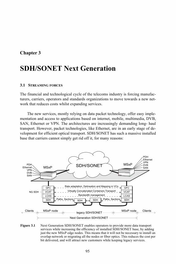
95
Chapter 3
SDH/SONET Next Generation
3.1 STREAMING FORCES
The financial and technological cycle of the telecoms industry is forcing manufac-turers, carriers, operators and standards organizations to move towards a new net-work that reduces costs whilst expanding services.
The new services, mostly relying on data packet technology, offer easy imple-mentation and access to applications based on internet, mobile, multimedia, DVB, SAN, Ethernet or VPN. The architectures are increasingly demanding long- haul transport. However, packet technologies, like Ethernet, are in an early stage of de-velopment for efficient optical transport. SDH/SONET has such a massive installed base that carriers cannot simply get rid off it, for many reasons:
SDH/SONET
SDH
LCAS
VCAT Virtually Concatenated Containers Transport
Bandwidth management
Paths, Sections
GFCRate adaptation, Delineation and Mapping in VCs
SDH SDH SDH
LCAS
VCAT
GFC
Paths, Sections
EthernetVPNDVBSAN
PDH
EthernetVPNDVBSAN
PDH
MSxPMSxP
MSxP nodelegacy SDH/SONET
MSxP nodeClients Clients
Figure 3.1 Next Generation SDH/SONET enables operators to provide more data transport services while increasing the efficiency of installed SDH/SONET base, by adding just the new MSxP edge nodes. This means that it will not be necessary to install an overlap network or migrating all the nodes or fiber optics. This reduces the cost per bit delivered, and will attract new customers while keeping legacy services.
Next Generation SDH/SONET
NG SDH
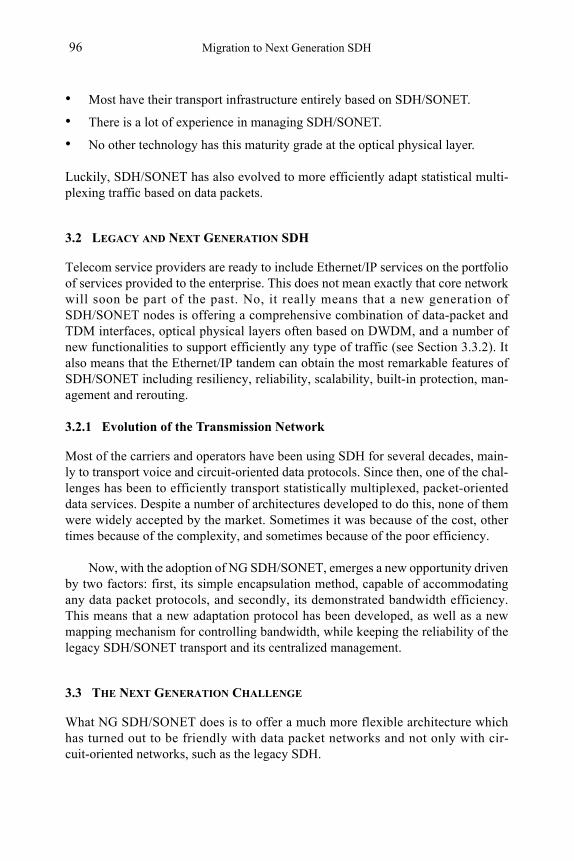
Migration to Next Generation SDH96
• Most have their transport infrastructure entirely based on SDH/SONET.
• There is a lot of experience in managing SDH/SONET.
• No other technology has this maturity grade at the optical physical layer.
Luckily, SDH/SONET has also evolved to more efficiently adapt statistical multi-plexing traffic based on data packets.
3.2 LEGACY AND NEXT GENERATION SDH
Telecom service providers are ready to include Ethernet/IP services on the portfolio of services provided to the enterprise. This does not mean exactly that core network will soon be part of the past. No, it really means that a new generation of SDH/SONET nodes is offering a comprehensive combination of data-packet and TDM interfaces, optical physical layers often based on DWDM, and a number of new functionalities to support efficiently any type of traffic (see Section 3.3.2). It also means that the Ethernet/IP tandem can obtain the most remarkable features of SDH/SONET including resiliency, reliability, scalability, built-in protection, man-agement and rerouting.
3.2.1 Evolution of the Transmission Network
Most of the carriers and operators have been using SDH for several decades, main-ly to transport voice and circuit-oriented data protocols. Since then, one of the chal-lenges has been to efficiently transport statistically multiplexed, packet-oriented data services. Despite a number of architectures developed to do this, none of them were widely accepted by the market. Sometimes it was because of the cost, other times because of the complexity, and sometimes because of the poor efficiency.
Now, with the adoption of NG SDH/SONET, emerges a new opportunity driven by two factors: first, its simple encapsulation method, capable of accommodating any data packet protocols, and secondly, its demonstrated bandwidth efficiency.This means that a new adaptation protocol has been developed, as well as a new mapping mechanism for controlling bandwidth, while keeping the reliability of the legacy SDH/SONET transport and its centralized management.
3.3 THE NEXT GENERATION CHALLENGE
What NG SDH/SONET does is to offer a much more flexible architecture which has turned out to be friendly with data packet networks and not only with cir-cuit-oriented networks, such as the legacy SDH.
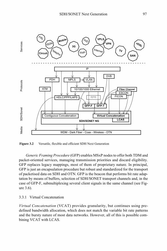
SDH/SONET Next Generation 97
Generic Framing Procedure (GFP) enables MSxP nodes to offer both TDM and packet-oriented services, managing transmission priorities and discard eligibility. GFP replaces legacy mappings, most of them of proprietary nature. In principal, GFP is just an encapsulation procedure but robust and standardized for the transport of packetised data on SDH and OTN. GFP is the beacon that performs bit rate adap-tation by means of buffers, selection of SDH/SONET transport channels and, in the case of GFP-F, submultiplexing several client signals in the same channel (see Fig-ure 3.6).
3.3.1 Virtual Concatenation
Virtual Concatenation (VCAT) provides granularity, but continues using pre-defined bandwidth allocation, which does not match the variable bit rate patterns and the bursty nature of most data networks. However, all of this is possible com-bining VCAT with LCAS.
LCASSDH/SONET NG
Contiguous Concatenation Virtual Concatenation
RPR
TV
Fiber Channel
ESCON
VoIP
VPN3G
Internet
GFP-F
PDH
Telepho
WDM - Dark Fiber - Coax - Wireless - OTN
VLAN
IP
MPLS
10/100/1000 Ethernet
Figure 3.2 Versatile, flexible and efficient SDH Next Generation
FICON
DVB
GFP-T
SANCircuit
xDSL
ATM
HDLC/PPP/LAPS
Ser
vice
sP
roto
cols
Me
dia
SD
H/S
one
t
Mobile VPLSFRL VoD
ISDN
Migration to Next Generation SDH98
3.3.2 The New Network Elements
Under the generic name of Multiservice Platforms (MSxP) we find a new set of nodes that combined with the existing REG, ADM and DXC configure the topolo-gies of the Next Generation SDH/SONET.
To make data transport more efficient, SDH/SONET has adopted a new set of pro-tocols that are being installed on the new nodes. These nodes should provide all the data and circuit interfaces clients demand, and be interconnected with the old equipment that is still running.
3.3.2.1 Multiservice Provisioning Platform
A Multiservice Provisioning Platform (MSPP) is basically the result of the evolution of legacy ADM and TDM interfaces and optical interfaces, to a type of access node that includes a set of:
• legacy TDM interfaces
• data interfaces, such as Ethernet, GigE, Fiber Channel, or DVB
• NG SDH/SONET functionalities such as GFP, VCAT and LCAS
• optical interfaces from STM-0/STS-1 to STM-64/OC-192
Figure 3.3 NG SDH/SONET network nodes
Legacy NE: Reg, Mux, ADM, DXC Multiservice Provisioning Platform (MSPP)
Multiservice Transport Platform (MSTP)
EthernetVPNDVBSAN
PDH
SDH
DWDM
Multiservice Switching Platform (MSSP)
SDHDWDMSDH
DWDMSDH
(classic ADM + packet interfaces)
(DXC-like)(MSPP + DWDM)
VPNDVBSAN
PDHEthernet
SDH
Client interfaces
SDH
SDH/SONET Next Generation 99
3.3.2.2 Multiservice Transport Platform
A Multiservice Transport Platform (MSTP) can be defined as a MSPP with DWDM functions to drop selected wavelengths at a site that will provide higher ag-gregated capacity to multiplex and to transport client signals. MSTP allows to inte-grate SDH/SONET, TDM and data services, with efficient WDM transport and wavelength switching. Typically, MSTPs are installed in the metro core network.
3.3.2.3 Multiservice Switching Platform
A Mult i serv ice Swi tch ing Pla t form (MSSP) is the NG equivalent for cross-connect, performing efficient traffic grooming and switching at STM-N/OC-M levels but also at VC level. MSSPs should support more than just data service mapping, namely true data services multiplexing and switching. MSSP is still emerging as a NG Network element, while MSPP and MSTP are quite ma-ture.
3.4 CORE TRANSPORT SERVICES
Today’s telecommunications services are based on a diverse combination of tech-nologies such as Ethernet, leased lines, IP, ATM, etc. Many of these technologies have always been clients of SDH, and others can probably also be when they need to extend their service range to wider areas.
Channelized networks organized in n x 64-kbps circuits like POTS, ISDN, or GSM, have been mapped efficiently into SDH/SONET containers in a natural way, be-cause all of them are circuit-oriented, just like SDH/SONET. More difficult has been to match the transport of data packets and best-effort technologies like Ether-net, IP, or DVB, because the use of statistical multiplexing makes traffic unpredict-able. This is the opposite of SDH/SONET, which is predictable and based onTime-Division Multiplexing (TDM).
3.4.1 Next-Generation SDH
Among all the technologies that moved towards the NG SDH, Ethernet is the most remarkable. Ethernet, the standard technology for local area networks (LANs), is cheap, easy to use, well-known, and always evolving toward higher rates. Now, when it is also being considered for access and metro networks, carriers have start-ed to look at SDH/SONET for transporting high volumes of Ethernet traffic to get long haul transport. To make that possible SDH has needed to match the bursty and connectionless nature of Ethernet using a number of protocols:
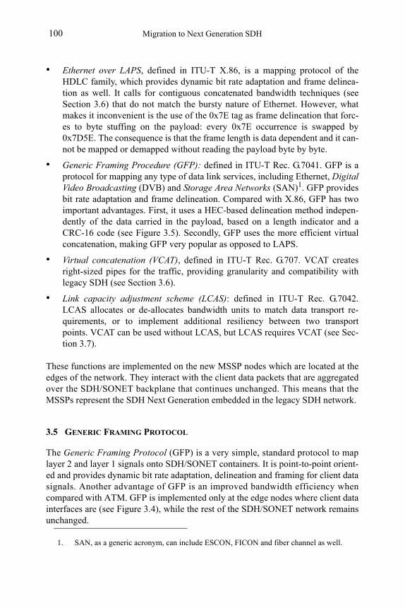
Migration to Next Generation SDH100
• Ethernet over LAPS, defined in ITU-T X.86, is a mapping protocol of the HDLC family, which provides dynamic bit rate adaptation and frame delinea-tion as well. It calls for contiguous concatenated bandwidth techniques (see Section 3.6) that do not match the bursty nature of Ethernet. However, what makes it inconvenient is the use of the 0x7E tag as frame delineation that forc-es to byte stuffing on the payload: every 0x7E occurrence is swapped by 0x7D5E. The consequence is that the frame length is data dependent and it can-not be mapped or demapped without reading the payload byte by byte.
• Generic Framing Procedure (GFP): defined in ITU-T Rec. G.7041. GFP is a protocol for mapping any type of data link services, including Ethernet, Digital Video Broadcasting (DVB) and Storage Area Networks (SAN)1. GFP provides bit rate adaptation and frame delineation. Compared with X.86, GFP has two important advantages. First, it uses a HEC-based delineation method indepen-dently of the data carried in the payload, based on a length indicator and a CRC-16 code (see Figure 3.5). Secondly, GFP uses the more efficient virtual concatenation, making GFP very popular as opposed to LAPS.
• Virtual concatenation (VCAT), defined in ITU-T Rec. G.707. VCAT creates right-sized pipes for the traffic, providing granularity and compatibility with legacy SDH (see Section 3.6).
• Link capacity adjustment scheme (LCAS): defined in ITU-T Rec. G.7042. LCAS allocates or de-allocates bandwidth units to match data transport re-quirements, or to implement additional resiliency between two transport points. VCAT can be used without LCAS, but LCAS requires VCAT (see Sec-tion 3.7).
These functions are implemented on the new MSSP nodes which are located at the edges of the network. They interact with the client data packets that are aggregated over the SDH/SONET backplane that continues unchanged. This means that the MSSPs represent the SDH Next Generation embedded in the legacy SDH network.
3.5 GENERIC FRAMING PROTOCOL
The Generic Framing Protocol (GFP) is a very simple, standard protocol to map layer 2 and layer 1 signals onto SDH/SONET containers. It is point-to-point orient-ed and provides dynamic bit rate adaptation, delineation and framing for client data signals. Another advantage of GFP is an improved bandwidth efficiency when compared with ATM. GFP is implemented only at the edge nodes where client data interfaces are (see Figure 3.4), while the rest of the SDH/SONET network remains unchanged.
1. SAN, as a generic acronym, can include ESCON, FICON and fiber channel as well.
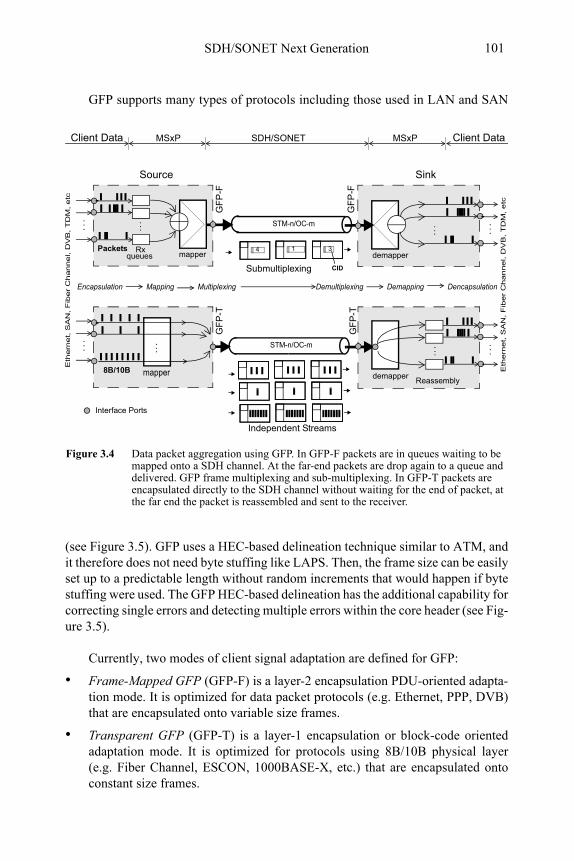
SDH/SONET Next Generation 101
GFP supports many types of protocols including those used in LAN and SAN
(see Figure 3.5). GFP uses a HEC-based delineation technique similar to ATM, and it therefore does not need byte stuffing like LAPS. Then, the frame size can be easily set up to a predictable length without random increments that would happen if byte stuffing were used. The GFP HEC-based delineation has the additional capability for correcting single errors and detecting multiple errors within the core header (see Fig-ure 3.5).
Currently, two modes of client signal adaptation are defined for GFP:
• Frame-Mapped GFP (GFP-F) is a layer-2 encapsulation PDU-oriented adapta-tion mode. It is optimized for data packet protocols (e.g. Ethernet, PPP, DVB) that are encapsulated onto variable size frames.
• Transparent GFP (GFP-T) is a layer-1 encapsulation or block-code oriented adaptation mode. It is optimized for protocols using 8B/10B physical layer (e.g. Fiber Channel, ESCON, 1000BASE-X, etc.) that are encapsulated onto constant size frames.
Sink
...
demapper
STM-n/OC-m
Figure 3.4 Data packet aggregation using GFP. In GFP-F packets are in queues waiting to be mapped onto a SDH channel. At the far-end packets are drop again to a queue and delivered. GFP frame multiplexing and sub-multiplexing. In GFP-T packets are encapsulated directly to the SDH channel without waiting for the end of packet, at the far end the packet is reassembled and sent to the receiver.
Client Data SDH/SONET Client Data
Source Sink
CIDSubmultiplexing
STM-n/OC-m
Encapsulation Mapping Multiplexing Demultiplexing Demapping Dencapsulation
......
RxPackets
MSxP
queues demapper
MSxP
mapper
8B/10B mapper
...
1 34
Reassembly
GF
P-F
GF
P-F
GF
P-T
GF
P-T
Independent Streams
Interface Ports
...
...
...
...
Eth
ern
et, S
AN
, F
iber
Channel, D
VB
, T
DM
, etc
Eth
ern
et, S
AN
, F
iber
Channel, D
VB
, T
DM
, etc
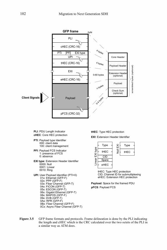
Migration to Next Generation SDH102
Figure 3.5 GFP frame formats and protocols. Frame delineation is done by the PLI indicating the length and cHEC which is the CRC calculated over the two octets of the PLI in a similar way as ATM does.
PTI
byte
PFI EXI typeUPI
PLI
cHEC (CRC-16)
tHEC (CRC-16)
EXI
eHEC (CRC-16)
pFCS (CRC-32)
Payload
Core Header
Payload Header
Extension Header(optional)
Payload
Check Sum(optional)
GFP frame
PLI: PDU Length IndicatorcHEC: Core HEC protection
PTI: Payload type Identifier000: client data100: client management
PFI: Payload FCS Indicator1: presence of FCS0: absence
EXI type: Extension Header Identifier0000: Null0001: Linear0010: Ring
UPI: User Payload Identifier (PTI=0)
Payload: Space for the framed PDU
pFCS: Payload FCS
01x: Ethernet (GFP-F)02x: PPP (GFP-F)03x: Fiber Channel (GFP-T)04x: FICON (GFP-T)05x: ESCON (GFP-T)06x: Gigabit Ethernet (GFP-T)08x: MAPOS (GFP-F)09x: DVB (GFP-T)0Ax: RPR (GFP-F)
0Cx: Async Fiber Channel (GFP-T)
scra
mble
d b
yte
s (
optional)
0Bx: Fiber Channel (GFP-F)
CIDSpare
Lin
ear
EX
I typ
e
Nul
l EX
I
tHEC: Type HEC protectionCID: Channel ID for submultiplexingeHEC: Extension HEC protection
tHEC
Type Type
tHEC
eHEC
EXI: Extension Header Identifier
4 bytes
4 bytes
0-60 bytes
n bytes
0-4
byte
s
tHEC: Type HEC protection
Client Signals
SDH/SONET Next Generation 103
3.5.1 Framed–Mapped GFP
Frame–Mapped GFP (GFP-F) drops the entire client packet into a GFP frame. The encapsulation process must receive the complete client packet, then, depending on the client protocol, specific signals are removed such as certain headers, idle codes, and interframe gaps to minimize the transmission size (see Figure 3.6).
GFP-F has an optional GFP extension header (see Figure 3.5), and the fields that can be used here are source/destination address, port numbers, Class of Service(CoS), etc. The Extension Header Identifier (EXI) linear type supports submulti-plexing onto a single path, by means of the Channel ID (CID) that enables submul-tiplexing over one VC channel in GFP-F mode (see Figure 3.4).
The EXI statistical submultiplexing is intended for carriers who want to im-prove bandwidth usage along simple point-to-point paths by adding traffic from dif-ferent low-rate sources in a single VCG. Carriers who need not only multiplexing but switching traffic will probably need a different approach. Traffic can be switched by means of MAC addresses or MPLS labels. These layer-2 switching capabilities are integrated in some MSSPs.
GFP and SDH/SONET without multiplexing or submultiplexing is a good choice for transporting Ethernet and implementing the Ethernet Private Line (EPL) service defined by the Metro Internet Forum (MEF) in intercity or metropolitan net-works.
GFP-F results in a more efficient transport, however, the encapsulation process-es described above increase latency, making GFP-F inappropriate for time-sensitive protocols. This is the reason why GFP-F is used for Ethernet, PPP/IP and HDLC-like protocols where efficiency and flexibility are more important than delays.
3.5.2 Transparent GFP
Transparent GFP (GFP-T) is a protocol-independent encapsulation method in which all client signals are mapped into fixed-length GFP frames. Once the GFP frame is filled up, is transmitted immediately without waiting for the entire client data packet to be received. Therefore, it is a layer-1 mapping mechanism, because all the client characters, without exception, are transported to the far end. GFP-T is completely blind to the meaning of the codes, and it does not distinguish between information, inter-frame gaps, headers, flow control characters, overhead or idle codes.
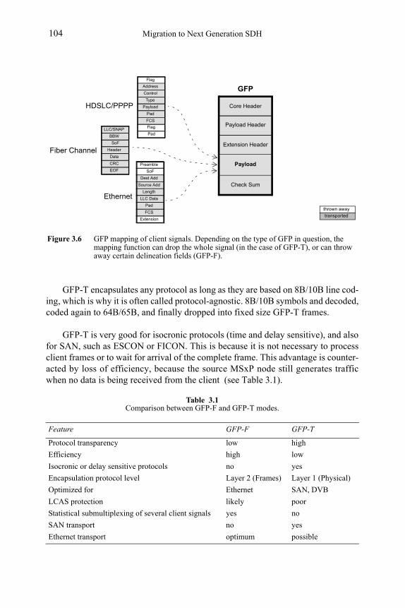
Migration to Next Generation SDH104
GFP-T encapsulates any protocol as long as they are based on 8B/10B line cod-ing, which is why it is often called protocol-agnostic. 8B/10B symbols and decoded, coded again to 64B/65B, and finally dropped into fixed size GFP-T frames.
GFP-T is very good for isocronic protocols (time and delay sensitive), and also for SAN, such as ESCON or FICON. This is because it is not necessary to process client frames or to wait for arrival of the complete frame. This advantage is counter-acted by loss of efficiency, because the source MSxP node still generates traffic when no data is being received from the client (see Table 3.1).
Table 3.1Comparison between GFP-F and GFP-T modes.
Feature GFP-F GFP-T
Protocol transparency low high
Efficiency high low
Isocronic or delay sensitive protocols no yes
Encapsulation protocol level Layer 2 (Frames) Layer 1 (Physical)
Optimized for Ethernet SAN, DVB
LCAS protection likely poor
Statistical submultiplexing of several client signals yes no
SAN transport no yes
Ethernet transport optimum possible
Figure 3.6 GFP mapping of client signals. Depending on the type of GFP in question, the mapping function can drop the whole signal (in the case of GFP-T), or can throw away certain delineation fields (GFP-F).
SoF
Dest Add
Source Add
Length
LLC Data
Pad
FCS
Flag
Address
Control
Type
Payload
Pad
FCS
Extension
Flag
Pad
Preamble
Ethernet
HDSLC/PPPP
BBW
SoF
Header
Data
CRC
EOF
LLC/SNAP
Fiber Channel
Core Header
Payload Header
Extension Header
Payload
Check Sum
thrown away
transported
GFP
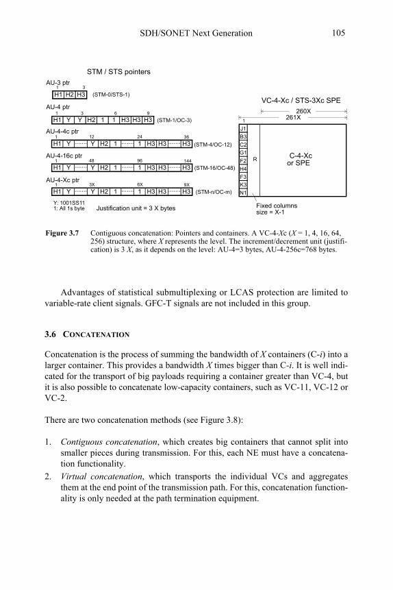
SDH/SONET Next Generation 105
Advantages of statistical submultiplexing or LCAS protection are limited to variable-rate client signals. GFC-T signals are not included in this group.
3.6 CONCATENATION
Concatenation is the process of summing the bandwidth of X containers (C-i) into a larger container. This provides a bandwidth X times bigger than C-i. It is well indi-cated for the transport of big payloads requiring a container greater than VC-4, but it is also possible to concatenate low-capacity containers, such as VC-11, VC-12 or VC-2.
There are two concatenation methods (see Figure 3.8):
1. Contiguous concatenation, which creates big containers that cannot split into smaller pieces during transmission. For this, each NE must have a concatena-tion functionality.
2. Virtual concatenation, which transports the individual VCs and aggregates them at the end point of the transmission path. For this, concatenation function-ality is only needed at the path termination equipment.
Figure 3.7 Contiguous concatenation: Pointers and containers. A VC-4-Xc (X = 1, 4, 16, 64, 256) structure, where X represents the level. The increment/decrement unit (justifi-cation) is 3 X, as it depends on the level: AU-4=3 bytes, AU-4-256c=768 bytes.
G1
F2
H4
J1
B3
C2
F3
K3
N1
R
VC-4-Xc / STS-3Xc SPE
Fixed columns
261X
C-4-Xc
260X
1H1 Y Y H2 1 1 H3 H3 H3
H3
H1 Y Y....... H2 1 1....... H3 H3 H3.......
H2H1 1 3
1 9
1 36
3
12 24
H1 Y Y....... H2 1 1....... H3 H3 H3.......1 14448 96
AU-3 ptr
AU-4 ptr
AU-4-4c ptr
AU-4-16c ptr
H1 Y Y....... H2 1 1....... H3 H3 H3.......1 9X3X 6X
AU-4-Xc ptr
6
Y: 1001SS111: All 1s byte Justification unit = 3 X bytes
size = X-1
(STM-0/STS-1)
(STM-1/OC-3)
(STM-4/OC-12)
(STM-16/OC-48)
(STM-n/OC-m)
STM / STS pointers
or SPE
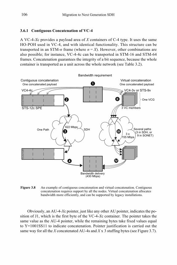
Migration to Next Generation SDH106
3.6.1 Contiguous Concatenation of VC-4
A VC-4-Xc provides a payload area of X containers of C-4 type. It uses the same HO-POH used in VC-4, and with identical functionality. This structure can be transported in an STM-n frame (where n = X). However, other combinations are also possible; for instance, VC-4-4c can be transported in STM-16 and STM-64 frames. Concatenation guarantees the integrity of a bit sequence, because the whole container is transported as a unit across the whole network (see Table 3.2).
Obviously, an AU-4-Xc pointer, just like any other AU pointer, indicates the po-sition of J1, which is the first byte of the VC-4-Xc container. The pointer takes the same value as the AU-4 pointer, while the remaining bytes take fixed values equal to Y=1001SS11 to indicate concatenation. Pointer justification is carried out the same way for all the X concatenated AU-4s and X x 3 stuffing bytes (see Figure 3.7).
G1F2H4
J1B3C2
F3K3N1
G1F2H4
J1B3C2
F3K3N1
Figure 3.8 An example of contiguous concatenation and virtual concatenation. Contiguous concatenation requires support by all the nodes. Virtual concatenation allocates bandwidth more efficiently, and can be supported by legacy installations.
Bandwidth requirement
G1F2H4
J1B3C2
F3K3N1
SDH
G1F2H4
J1B3C2
F3K3N1
One concatenated payload
G1F2H4
J1B3C2
F3K3N1
G1F2H4
J1B3C2
F3K3N1
G1F2H4
J1B3C2
F3K3N1
G1F2H4
J1B3C2
F3K3N1
VC4-4c VC4-3v or STS-9v
Bandwidth delivery
One Path Several paths
(430 Mbps)
2
1
3 III
4
II
IV
622 Mbps
3 x155 Mbps
Contiguous concatenation Virtual concatenation
STS-12c SPE
(3 in SDH, or9 in SONET)
One concatenated payload
One VCG
3 VC members
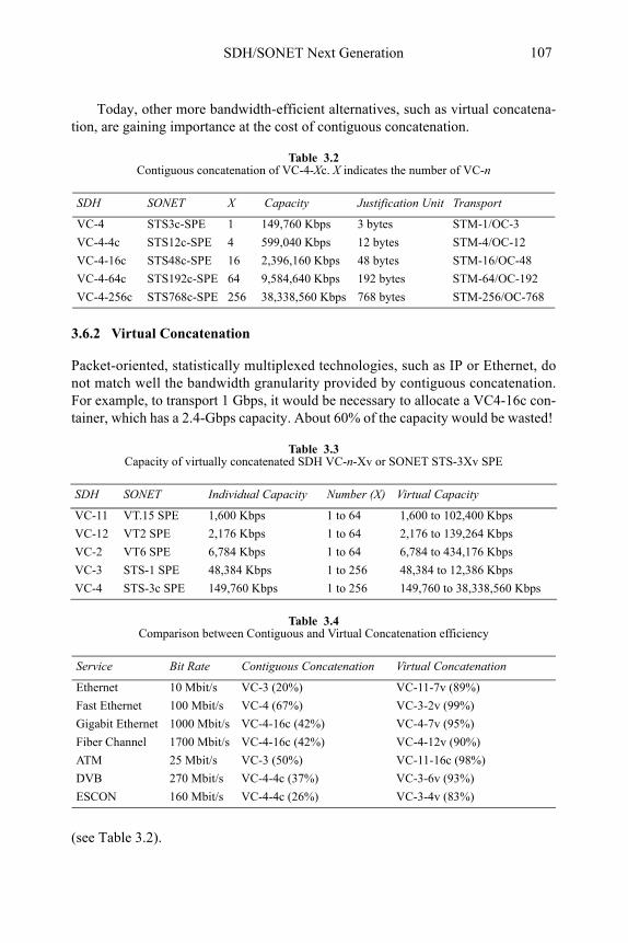
SDH/SONET Next Generation 107
Today, other more bandwidth-efficient alternatives, such as virtual concatena-tion, are gaining importance at the cost of contiguous concatenation.
3.6.2 Virtual Concatenation
Packet-oriented, statistically multiplexed technologies, such as IP or Ethernet, do not match well the bandwidth granularity provided by contiguous concatenation. For example, to transport 1 Gbps, it would be necessary to allocate a VC4-16c con-tainer, which has a 2.4-Gbps capacity. About 60% of the capacity would be wasted!
(see Table 3.2).
Table 3.2Contiguous concatenation of VC-4-Xc. X indicates the number of VC-n
SDH SONET X Capacity Justification Unit Transport
VC-4 STS3c-SPE 1 149,760 Kbps 3 bytes STM-1/OC-3
VC-4-4c STS12c-SPE 4 599,040 Kbps 12 bytes STM-4/OC-12
VC-4-16c STS48c-SPE 16 2,396,160 Kbps 48 bytes STM-16/OC-48
VC-4-64c STS192c-SPE 64 9,584,640 Kbps 192 bytes STM-64/OC-192
VC-4-256c STS768c-SPE 256 38,338,560 Kbps 768 bytes STM-256/OC-768
Table 3.3Capacity of virtually concatenated SDH VC-n-Xv or SONET STS-3Xv SPE
SDH SONET Individual Capacity Number (X) Virtual Capacity
VC-11 VT.15 SPE 1,600 Kbps 1 to 64 1,600 to 102,400 Kbps
VC-12 VT2 SPE 2,176 Kbps 1 to 64 2,176 to 139,264 Kbps
VC-2 VT6 SPE 6,784 Kbps 1 to 64 6,784 to 434,176 Kbps
VC-3 STS-1 SPE 48,384 Kbps 1 to 256 48,384 to 12,386 Kbps
VC-4 STS-3c SPE 149,760 Kbps 1 to 256 149,760 to 38,338,560 Kbps
Table 3.4Comparison between Contiguous and Virtual Concatenation efficiency
Service Bit Rate Contiguous Concatenation Virtual Concatenation
Ethernet 10 Mbit/s VC-3 (20%) VC-11-7v (89%)
Fast Ethernet 100 Mbit/s VC-4 (67%) VC-3-2v (99%)
Gigabit Ethernet 1000 Mbit/s VC-4-16c (42%) VC-4-7v (95%)
Fiber Channel 1700 Mbit/s VC-4-16c (42%) VC-4-12v (90%)
ATM 25 Mbit/s VC-3 (50%) VC-11-16c (98%)
DVB 270 Mbit/s VC-4-4c (37%) VC-3-6v (93%)
ESCON 160 Mbit/s VC-4-4c (26%) VC-3-4v (83%)
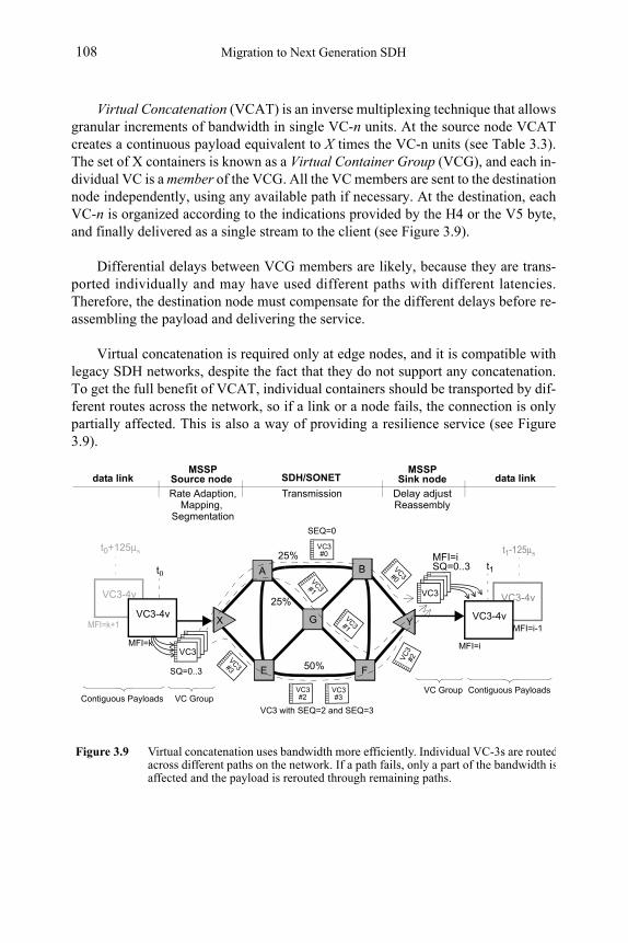
Migration to Next Generation SDH108
Virtual Concatenation (VCAT) is an inverse multiplexing technique that allows granular increments of bandwidth in single VC-n units. At the source node VCAT creates a continuous payload equivalent to X times the VC-n units (see Table 3.3). The set of X containers is known as a Virtual Container Group (VCG), and each in-dividual VC is a member of the VCG. All the VC members are sent to the destination node independently, using any available path if necessary. At the destination, each VC-n is organized according to the indications provided by the H4 or the V5 byte, and finally delivered as a single stream to the client (see Figure 3.9).
Differential delays between VCG members are likely, because they are trans-ported individually and may have used different paths with different latencies.Therefore, the destination node must compensate for the different delays before re-assembling the payload and delivering the service.
Virtual concatenation is required only at edge nodes, and it is compatible with legacy SDH networks, despite the fact that they do not support any concatenation. To get the full benefit of VCAT, individual containers should be transported by dif-ferent routes across the network, so if a link or a node fails, the connection is only partially affected. This is also a way of providing a resilience service (see Figure 3.9).
VC3-4vVC3-4v
Figure 3.9 Virtual concatenation uses bandwidth more efficiently. Individual VC-3s are routedacross different paths on the network. If a path fails, only a part of the bandwidth isaffected and the payload is rerouted through remaining paths.
A B
FE
X YG
50%
25%
VC3-4vVC3-4vMFI=k+1
MFI=k
SQ=0..3
MFI=i
MFI=i-1
MFI=iSQ=0..3 t1
t1-125μst0+125μs
t0
Rate Adaption, Transmission
VC3
555
555
Source node Sink node
VC GroupContiguous PayloadsVC3 with SEQ=2 and SEQ=3
SDH/SONET
Delay adjust
VC Group Contiguous Payloads
SEQ=0
25%
MSSP MSSP
VC3
VC3
#0
VC
3#2
VC3#3
VC3#3
VC3#1
VC3#1
ReassemblyMapping, Segmentation
data link data link
VC3#2
VC3#0
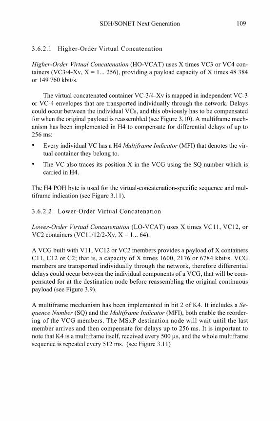
SDH/SONET Next Generation 109
3.6.2.1 Higher-Order Virtual Concatenation
Higher-Order Virtual Concatenation (HO-VCAT) uses X times VC3 or VC4 con-tainers (VC3/4-Xv, X = 1... 256), providing a payload capacity of X times 48 384 or 149 760 kbit/s.
The virtual concatenated container VC-3/4-Xv is mapped in independent VC-3 or VC-4 envelopes that are transported individually through the network. Delays could occur between the individual VCs, and this obviously has to be compensated for when the original payload is reassembled (see Figure 3.10). A multiframe mech-anism has been implemented in H4 to compensate for differential delays of up to 256 ms:
• Every individual VC has a H4 Multiframe Indicator (MFI) that denotes the vir-tual container they belong to.
• The VC also traces its position X in the VCG using the SQ number which is carried in H4.
The H4 POH byte is used for the virtual-concatenation-specific sequence and mul-tiframe indication (see Figure 3.11).
3.6.2.2 Lower-Order Virtual Concatenation
Lower-Order Virtual Concatenation (LO-VCAT) uses X times VC11, VC12, or VC2 containers (VC11/12/2-Xv, X = 1... 64).
A VCG built with V11, VC12 or VC2 members provides a payload of X containers C11, C12 or C2; that is, a capacity of X times 1600, 2176 or 6784 kbit/s. VCG members are transported individually through the network, therefore differential delays could occur between the individual components of a VCG, that will be com-pensated for at the destination node before reassembling the original continuous payload (see Figure 3.9).
A multiframe mechanism has been implemented in bit 2 of K4. It includes a Se-quence Number (SQ) and the Multiframe Indicator (MFI), both enable the reorder-ing of the VCG members. The MSxP destination node will wait until the last member arrives and then compensate for delays up to 256 ms. It is important to note that K4 is a multiframe itself, received every 500 μs, and the whole multiframe sequence is repeated every 512 ms. (see Figure 3.11)
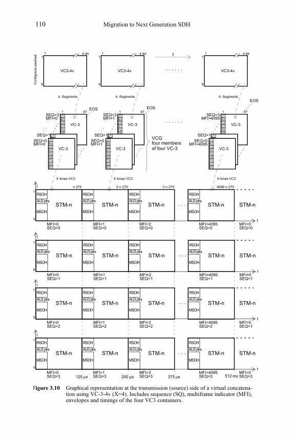
Migration to Next Generation SDH110
G1F2H4
J1B3C2
F3K3N1
VC-3G1F2H4
J1B3C2
F3K3N1
Figure 3.10 Graphical representation at the transmission (source) side of a virtual concatena-tion using VC-3-4v (X=4). Includes sequence (SQ), multiframe indicator (MFI), envelopes and timings of the four VC3 containers.
125 μs
AU3 ptrs
RSOH
MSOH
MFI=0
STM-n
SEQ=0
9
1
1 n·270
AU3 ptrs
RSOH
MSOH
MFI=1
STM-n
SEQ=0
2·n·270
AU3 ptrs
RSOH
MSOH
MFI=2
STM-n
SEQ=0
3·n·270
AU3 ptrs
RSOH
MSOH
MFI=4095
STM-n
SEQ=0
4096·n·270
250 μs 375 μs
MFI=0
STM-n. . .
VC-3G1F2H4
J1B3C2
F3K3N1
SEQ=0
VC-3
MFI=0
SEQ=1
SEQ=3MFI=0.
..
9
1
VC3-4v
871
4·841
4 -Segments
X times VC3
G1F2H4
J1B3C2
F3K3N1
VC-3G1F2H4
J1B3C2
F3K3N1
VC-3G1F2H4
J1B3C2
F3K3N1
SEQ=0
VC-3
MFI=1
SEQ=1
SEQ=3MFI=1.
..
9
1
VC3-4v
871
4·841
4 -Segments
X times VC3
G1F2H4
J1B3C2
F3K3N1
VC-3G1F2H4
J1B3C2
F3K3N1
VC-3G1F2H4
J1B3C2
F3K3N1
SEQ=0
VC-3
MFI=4095
SEQ=1
SEQ=3MFI=4095.
..
9
1
VC3-4v
871
4·841
4 -Segments
X times VC3
. . . . . .
. . . . . .
four members
t
. . .
.
. . .
.
. . .
.
. . .
.
. . .
.
. . .
.
t
SEQ=0
EOS EOS
EOS
Co
ntig
uous
pa
yloa
d
VCG
AU3 ptrs
RSOH
MSOH
MFI=0
STM-n
SEQ=1
9
1
1
AU3 ptrs
RSOH
MSOH
MFI=1
STM-n
SEQ=1
AU3 ptrs
RSOH
MSOH
MFI=2
STM-n
SEQ=1
AU3 ptrs
RSOH
MSOH
MFI=4095
STM-n
SEQ=1MFI=0
STM-n. . .
t
SEQ=1
AU3 ptrs
RSOH
MSOH
MFI=0
STM-n
SEQ=3
9
1
1
AU3 ptrs
RSOH
MSOH
MFI=1
STM-n
SEQ=3
AU3 ptrs
RSOH
MSOH
MFI=2
STM-n
SEQ=3
AU3 ptrs
RSOH
MSOH
MFI=4095
STM-n
SEQ=3MFI=0
STM-n. . .
t
SEQ=3
. . . . . .
. . . . . .
. . . . . .
. . . . . .
512 ms
AU3 ptrs
RSOH
MSOH
MFI=0
STM-n
SEQ=2
9
1
1
AU3 ptrs
RSOH
MSOH
MFI=1
STM-n
SEQ=2
AU3 ptrs
RSOH
MSOH
MFI=2
STM-n
SEQ=2
AU3 ptrs
RSOH
MSOH
MFI=4095
STM-n
SEQ=2MFI=0
STM-n. . .
t
SEQ=1
of four VC-3
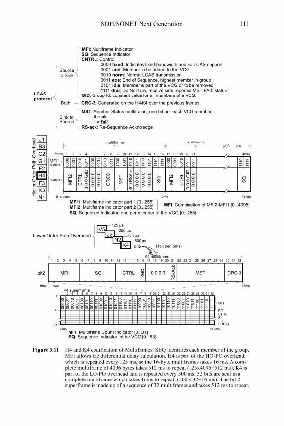
SDH/SONET Next Generation 111
K4 multiframe
MFI: Multiframe Count Indicator [0...31] SQ: Sequence Indicator int he VCG [0...63]
SQMFI
1 2 4 6 8 10 12 143 5 7 9 11 13 15 16
16ms
CTRL GID MST0 0 0 0
17 18 20 22 24 26 28 3019 21 23 25 27 29 31 32
CRC-3
RS
-Ack
Figure 3.11 H4 and K4 codification of Multiframes. SEQ identifies each member of the group, MFI allows the differential delay calculation. H4 is part of the HO-PO overhead, which is repeated every 125 ms, so the 16-byte multiframes takes 16 ms. A com-plete multiframe of 4096 bytes takes 512 ms to repeat (125x4096=512 ms). K4 is part of the LO-PO overhead and is repeated every 500 ms. 32 bits are sent in a complete multiframe which takes 16ms to repeat. (500 x 32=16 ms). The bit-2 superframe is made up of a sequence of 32 multiframes and takes 512 ms to repeat.
V5Lower Order Path Overhead
125 μs250 μs
375 μs500 μs
(1bit per .5ms)bit2
bit2
000
01
000
10
001
00
001
10
010
00
010
10
011
00
011
10
000
11
001
01
001
11
010
01
010
11
1101
011
11
000
00
1 2 4 6 8 10 12 143 5 7 9 11 13 15 16
MFI
512ms
011
01
100
01
100
10
101
00
101
10
110
00
110
10
1110
0
1111
0
100
11
101
01
101
11
110
01
110
11
1101
1111
1
100
00
17 18 20 22 24 26 28 3019 21 23 25 27 29 31 32
1110
1
1
SQCTRL
..
CRC-3
0001
0010
0100
011
0
1000
1010
110
0
111
0
0011
0101
0111
1001
1011
110
1
1111
0000
0001
0010 4
111
0
0011
1111
0000
1 2 256
0011
CT
RL
0 0
0 0
CR
C8
MS
T
000
RS
Ack
0 0
0 0
SQ
0 0
0 G
ID
0 0
0 0
0 0
0 0
0 0
0 0
MF
I2
CT
RL
MF
I2
0 0
0 G
ID
SQ
0 0
0 0
1 2 4 6 8 10 12 143 5 7 9 11 13 15 16 409617 18 19 20 21
5-8bits
1-4bits
frame
MFI1
0ms 2ms 512mstime
G1F2H4
J1B3C2
F3K3N1
multiframe multiframe
Hig
her
Ord
er
Pa
th O
verh
ead
J2N2
K4
MFI2: Multiframe indicator part 2 [0...255] MFI: Combination of MFI2-MFI1 [0...4095]MFI1: Multiframe indicator part 1 [0...255]
SQ: Sequence Indicator, one per member of the VCG [0...255]
32
time .5ms
4
0
0ms
K4 superframe
0000 fixed: Indicates fixed bandwidth and no LCAS support0001 add: Member to be added to the VCG0010 norm: Normal LCAS transmission0011 eos: End of Sequence, highest member in group0101 idle: Member is part of the VCG or to be removed1111 dnu: Do Not Use, receive side reported MST FAIL status
CNTRL: Control
GID: Group Id. constant value for all members of a VCG.
CRC-3: Generated on the H4/K4 over the previous frames.
MST: Member Status multiframe, one bit per each VCG member
RS-ack: Re-Sequence Acknoledge
0 = ok 1 = fail
LCASprotocol
Sourceto Sink
SQ: Sequence IndicatorMFI: Multiframe Indicator
SourceSink to
Both
Migration to Next Generation SDH112
3.6.3 VCAT Setup
When installing or maintaining VCAT, it is important to carry out a number of tests to verify not only the performance of the whole Virtual Concatenation, but also every single member of the VCG (see Figure 2). For reassembling the original client data, all the members of the VCG must arrive at the far end, keeping the delay be-tween the first and the last member of a VCG below 256 ms. A missing member pre-vents the reconstruction of the payload, and if the problem persists, it causes a fault that would require reconfiguring the VCAT pipe. Additionally, jitter and wander on individual paths can cause anomalies (errors) in the transport service.
BER, latency, and event tests should verify the capacity of the network to pro-vide the service. The VCAT granularity capacity has to be checked as well, by add-ing/removing members. To verify the reassembly operation, it is necessary to use a tester with the capability to insert differential delays in individual members of a VC.
3.7 LINK CAPACITY ADJUSTMENT SCHEME
The Link Capacity Adjustment Scheme (LCAS), standardized by the ITU-T as G.7042, was designed to manage the bandwidth allocation of a VCAT path.
What LCAS can do will be explained in the following paragraphs. However, what LCAS cannot do is to adapt the size of the VCAT channel according to the traffic pattern at any time. This would require direct interaction between the LCAS node and the control plane of the network, and it is not possible yet.
3.7.1 LCAS Protocol
The LCAS protocol can add and remove members of a VCG1, controlling the band-width of a live VCAT channel. Between the source and the sink LCAS is executed, monitoring member status and changing VCAT bandwidth use. LCAS messages are embedded in every VC member of the group providing multiple redundancy2.
Using messages embedded in H4 or K4 (see Figure 3.11) LCAS establishes a protocol between the source node and the sink node (see Figure 3.13 and Figure
1. This means that LCAS needs VCAT to work. However, VCAT does not necessarily need LCAS.
2. It is of key importance to realise that all LCAS messages from sink to source are rep-licated over each member path of the VCG. That is not true for the messages from source to sink, which are specific for each member. The sink-to-source redundancy enables the management of all member seven under a severe failure state.
SDH/SONET Next Generation 113
3.12) to control the concatenated group. Control messages between source to sink are a point-to-point communication. From source to sink the following information is delivered:
• Multi-Frame Indicator (MFI) keeps the multiframe sequence.
• Sequence Indicator (SQ) indicates member’s sequence to reassemble correctly the client signal that was split and sent through several paths.
• Control (CTRL) contains the LCAS protocol messages from source to sink. Possible messages are fixed, add, norm, eos, idle, and dnu.
• Group Identification (GID) is a constant value for all members of a VCG.
Control messages from sink to source include:
• Member Status (MST), which indicates to source each member status: fail orOK.
• Re-Sequence Acknowledge (RS-Ack) is an acknowledgment of renumbering of a sequence when a new member has been selected as eos.
With these control messages LCAS is also able to modify the pipe size of a VCAT channel, for example eliminating a member of the VCG that arrives with an unacceptable bit error rate, or does not arrive at all. When a capacity adjustment hap-pens the nodes restore channel capacity in a few milliseconds.
3.7.2 Light over LCAS
It is important to note that LCAS alone cannot automatically provision dynamic bandwidth depending on the traffic demand. It cannot compute, nor establish routes to take advantage of virtual concatenation. That would be really complex and would require not only a comprehensive analysis of the traffic, but also the control of SDH/SONET architecture to set up and clear up circuits. That is far beyond thecapabilities of LCAS. Route provisioning is in the hands of the Network Manage-ment System (NMS) (see Figure 3.12).
So, LCAS has been designed to help network operators to efficiently control NG SDH connections established at VCAT sites. The use of LCAS is not compulsory, but improves VCAT management. LCAS monitors a VCAT channel, removing or adding members to the VCG, for example after a failure detection. When at the sink side LCAS detects a failure, it sends a message to the source to remove affected member(s) of the group (see Figure 3.13). LCAS also manages the protocol to in-crease or decrease VCGs when it receives an indication from the NMS.
Consequently, LCAS operates inside of the core network without any interface at all to the external world (see Figure 3.14).
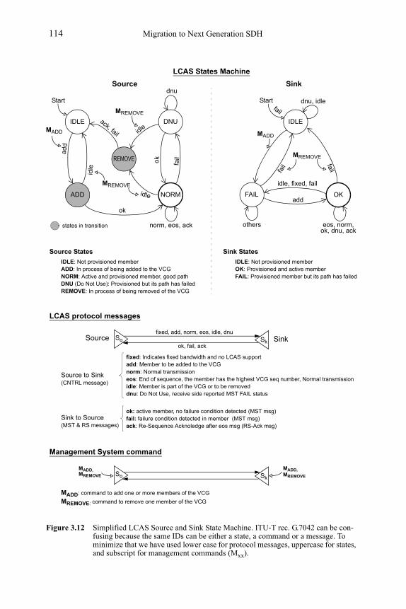
Migration to Next Generation SDH114
Figure 3.12 Simplified LCAS Source and Sink State Machine. ITU-T rec. G.7042 can be con-fusing because the same IDs can be either a state, a command or a message. To minimize that we have used lower case for protocol messages, uppercase for states, and subscript for management commands (Mxx).
Start
MADD
MREMOVE
IDLE
ADD NORM
REMOVE
DNU
add
norm, eos, ack
failok
ack, fail idle
idle
ok
idle
MREMOVE
dnu
OK
IDLE
FAIL
eos, norm,
MADD
fail
ok, dnu, ack
Startfail
others
MREMOVE
idle, fixed, fail
add
fail
fixed: Indicates fixed bandwidth and no LCAS supportadd: Member to be added to the VCGnorm: Normal transmissioneos: End of sequence, the member has the highest VCG seq number, Normal transmissionidle: Member is part of the VCG or to be removeddnu: Do Not Use, receive side reported MST FAIL status
ack: Re-Sequence Acknoledge after eos msg (RS-Ack msg)
ok: active member, no failure condition detected (MST msg)fail: failure condition detected in member (MST msg)
LCAS protocol messages
Source to Sink
Source
IDLE: Not provisioned memberADD: In process of being added to the VCGNORM: Active and provisioned member, good pathDNU (Do Not Use): Provisioned but its path has failedREMOVE: In process of being removed of the VCG
Sink
IDLE: Not provisioned memberOK: Provisioned and active memberFAIL: Provisioned member but its path has failed
Source States Sink States
LCAS States Machine
(CNTRL message)
Sink to Source(MST & RS messages)
Management System command
MADD: command to add one or more members of the VCG
MREMOVE: command to remove one member of the VCG
states in transition
So Sk
Sinkfixed, add, norm, eos, idle, dnu
ok, fail, ackSource So Sk
MADD, MADD,MREMOVEMREMOVE
dnu, idle
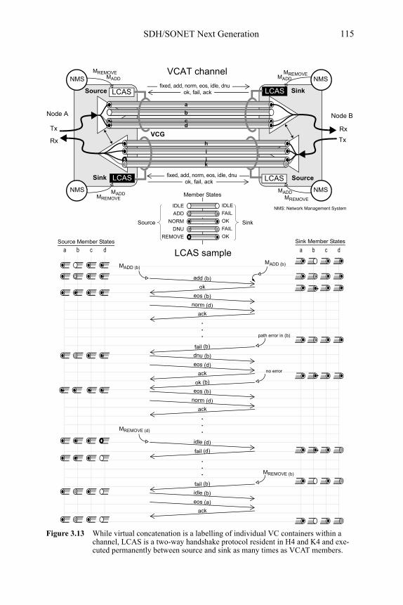
SDH/SONET Next Generation 115
a b c d a b c d
Sink
Source
LCAS
LCAS
Figure 3.13 While virtual concatenation is a labelling of individual VC containers within a channel, LCAS is a two-way handshake protocol resident in H4 and K4 and exe-cuted permanently between source and sink as many times as VCAT members.
VCGTx Rx
Source
TxRx
Sink
VCAT channel
LCAS
LCAS
Node A
fixed, add, norm, eos, idle, dnuok, fail, ack
IDLE IDLE
ADD FAIL
NORM OK
DNU FAIL
REMOVE OK
a
bcd
h
ijk
add (b)
fixed, add, norm, eos, idle, dnuok, fail, ack
ack
eos (b)
norm (d)
fail (b)
ok
dnu (b)
eos (d)
ack
ok (b)
eos (b)
norm (d)
MADD (b)
ack
MADD (b)
MREMOVE (d)
idle (d)
fail (d)
idle (b)
fail (b)
eos (a)
.
.
.
MADDMREMOVE
Node B
NMS
MADD
MREMOVE
NMS
MADDMREMOVE
NMS
MADDMREMOVE
NMS
NMS: Network Management System
SinkSource
LCAS sample
ack
MREMOVE (b)
.
.
.
.
.
.path error in (b)
no error
Member States
Sink Member StatesSource Member States
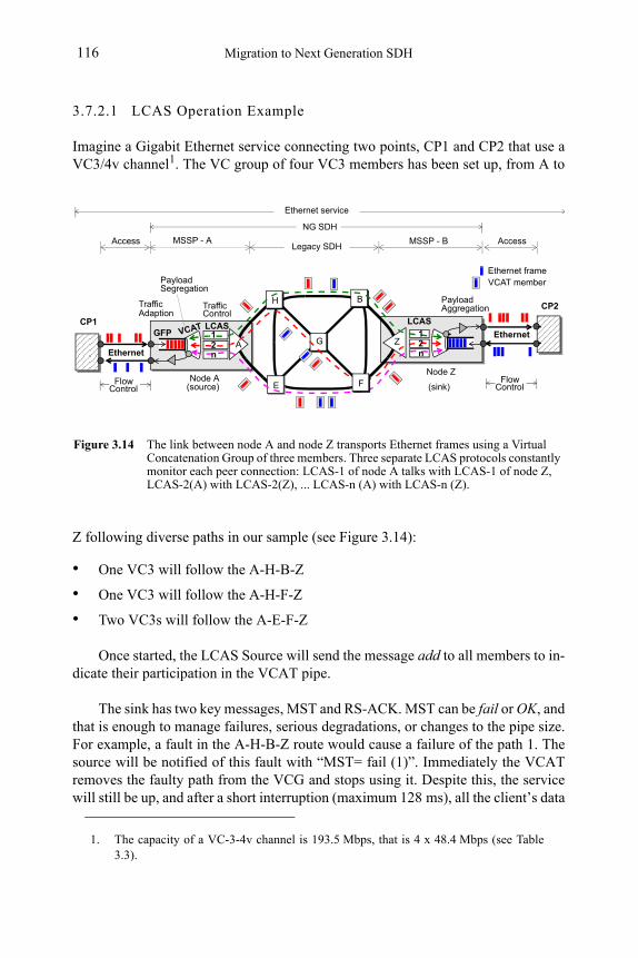
Migration to Next Generation SDH116
3.7.2.1 LCAS Operation Example
Imagine a Gigabit Ethernet service connecting two points, CP1 and CP2 that use a VC3/4v channel1. The VC group of four VC3 members has been set up, from A to
Z following diverse paths in our sample (see Figure 3.14):
• One VC3 will follow the A-H-B-Z
• One VC3 will follow the A-H-F-Z
• Two VC3s will follow the A-E-F-Z
Once started, the LCAS Source will send the message add to all members to in-dicate their participation in the VCAT pipe.
The sink has two key messages, MST and RS-ACK. MST can be fail or OK, and that is enough to manage failures, serious degradations, or changes to the pipe size. For example, a fault in the A-H-B-Z route would cause a failure of the path 1. The source will be notified of this fault with “MST= fail (1)”. Immediately the VCAT removes the faulty path from the VCG and stops using it. Despite this, the service will still be up, and after a short interruption (maximum 128 ms), all the client’s data
1. The capacity of a VC-3-4v channel is 193.5 Mbps, that is 4 x 48.4 Mbps (see Table 3.3).
GFP
Figure 3.14 The link between node A and node Z transports Ethernet frames using a Virtual Concatenation Group of three members. Three separate LCAS protocols constantly monitor each peer connection: LCAS-1 of node A talks with LCAS-1 of node Z, LCAS-2(A) with LCAS-2(Z), ... LCAS-n (A) with LCAS-n (Z).
Ethernet
Ethernet frame
VCAT
Traffic
LCAS
H B
G
E
Payload Segregation
TrafficControlAdaption
MSSP - A
Ethernet
NG SDH
12n
12n
Legacy SDHMSSP - BAccess Access
Payload Aggregation
Flow Control
LCAS
VCAT member
Node ANode Z
Flow Control
Ethernet service
F
A Z
(source) (sink)
CP1
CP2
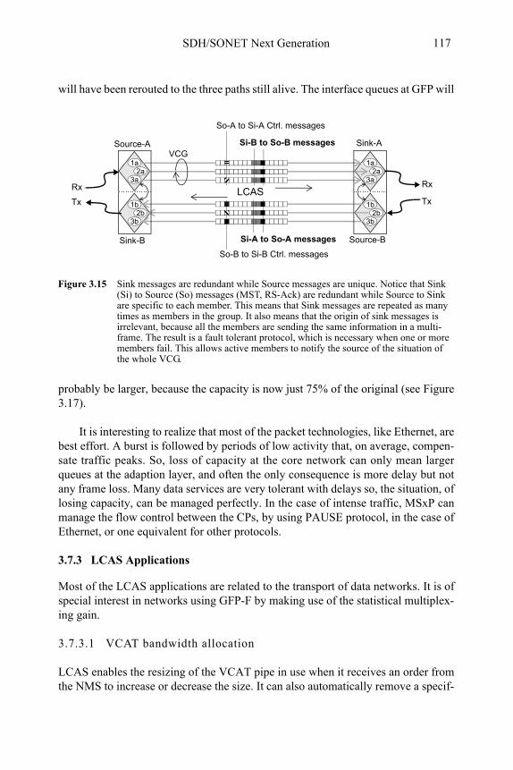
SDH/SONET Next Generation 117
will have been rerouted to the three paths still alive. The interface queues at GFP will
probably be larger, because the capacity is now just 75% of the original (see Figure 3.17).
It is interesting to realize that most of the packet technologies, like Ethernet, are best effort. A burst is followed by periods of low activity that, on average, compen-sate traffic peaks. So, loss of capacity at the core network can only mean larger queues at the adaption layer, and often the only consequence is more delay but not any frame loss. Many data services are very tolerant with delays so, the situation, of losing capacity, can be managed perfectly. In the case of intense traffic, MSxP can manage the flow control between the CPs, by using PAUSE protocol, in the case of Ethernet, or one equivalent for other protocols.
3.7.3 LCAS Applications
Most of the LCAS applications are related to the transport of data networks. It is of special interest in networks using GFP-F by making use of the statistical multiplex-ing gain.
3.7.3.1 VCAT bandwidth allocation
LCAS enables the resizing of the VCAT pipe in use when it receives an order from the NMS to increase or decrease the size. It can also automatically remove a specif-
1a2a
3a
1b2b
3b
1a2a
3a
1b2b
3b
Source-A
Sink-B
Sink-A
Source-B
LCAS
Si-A to So-A messages
So-B to Si-B Ctrl. messages
Si-B to So-B messages
So-A to Si-A Ctrl. messages
Rx
Tx
VCG
Figure 3.15 Sink messages are redundant while Source messages are unique. Notice that Sink (Si) to Source (So) messages (MST, RS-Ack) are redundant while Source to Sink are specific to each member. This means that Sink messages are repeated as many times as members in the group. It also means that the origin of sink messages is irrelevant, because all the members are sending the same information in a multi-frame. The result is a fault tolerant protocol, which is necessary when one or more members fail. This allows active members to notify the source of the situation of the whole VCG.
Rx
Tx
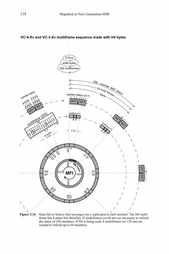
Migration to Next Generation SDH118
025
5
160
159
9596
128
127
192191
22422331
32
409
5
3072
0
MFI 6364
204
8
1024
bytes
H4
16 bytes
multiframe (2
25)
2 ms
0 21 3member
8 9
4 65 7
255
.....
status (0-7)
02
13
64ms
256 -
MST MST
member MST status
32 multi frames
VC-4-Xv and VC-3-Xv multiframe sequence made with H4 bytes
89
CTR
L 0 CR
C8
MST RSA 0
SQ
GID
0
0
0
MFI
1
8 9
16MFI
512ms
4096 bytes
256 multiframes
ok / fail
225
multiframe (31)
multiframe (0)
member status
ok / failok / fail
ok / failok / fail
ok / failok / fail
ok / fail
MST
MST
MST MST
MSTMST
255.....
02
13
MS
TM
ST
Figure 3.16 Sink (Si) to Source (So) messages are a replicated in each member. The H4 multi-frame has 8 status bits therefore 32 multiframes (or 64 ms) are necessary to refresh the status of 256 members. If H4 is being used, 8 multiframes (or 128 ms) are needed to refresh up to 64 members.
2 ms
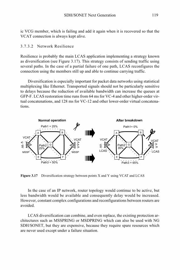
SDH/SONET Next Generation 119
ic VCG member, which is failing and add it again when it is recovered so that the VCAT connection is always kept alive.
3.7.3.2 Network Resilience
Resilience is probably the main LCAS application implementing a strategy known as diversification (see Figure 3.17). This strategy consists of sending traffic using several paths. In the case of a partial failure of one path, LCAS reconfigures the connection using the members still up and able to continue carrying traffic.
Diversification is especially important for packet data networks using statistical multiplexing like Ethernet. Transported signals should not be particularly sensitive to delays because the reduction of available bandwidth can increase the queues at GFP-F. LCAS restoration time runs from 64 ms for VC-4 and other higher-order vir-tual concatenations, and 128 ms for VC-12 and other lower-order virtual concatena-tions.
In the case of an IP network, router topology would continue to be active, but less bandwidth would be available and consequently delay would be increased. However, constant complex configurations and reconfigurations between routers are avoided.
LCAS diversification can combine, and even replace, the existing protection ar-chitectures such as MSSPRING or MSDPRING which can also be used with NG SDH/SONET, but they are expensive, because they require spare resources which are never used except under a failure situation.
Figure 3.17 Diversification strategy between points X and Y using VCAT and LCAS
Path1 = 25%
Path3 = 50%
A B
FE
X YG
A B
FE
X YG
Path1= 0%
Path3 = 65%
Normal operation After breakdown
VCATVCAT VCAT VCAT
LCASLCASMSSPMSSP
Path225%
Path235%
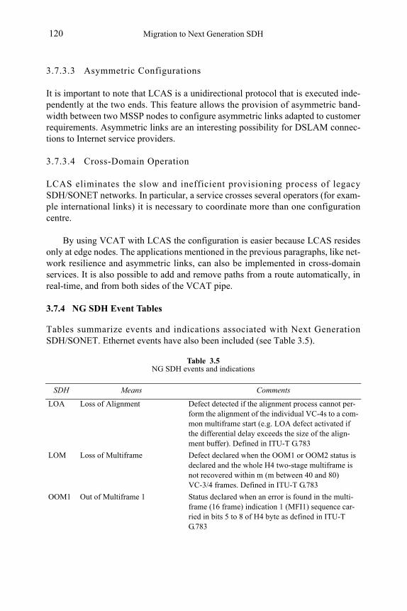
Migration to Next Generation SDH120
3.7.3.3 Asymmetric Configurations
It is important to note that LCAS is a unidirectional protocol that is executed inde-pendently at the two ends. This feature allows the provision of asymmetric band-width between two MSSP nodes to configure asymmetric links adapted to customer requirements. Asymmetric links are an interesting possibility for DSLAM connec-tions to Internet service providers.
3.7.3.4 Cross-Domain Operation
LCAS eliminates the slow and inefficient provisioning process of legacy SDH/SONET networks. In particular, a service crosses several operators (for exam-ple international links) it is necessary to coordinate more than one configuration centre.
By using VCAT with LCAS the configuration is easier because LCAS resides only at edge nodes. The applications mentioned in the previous paragraphs, like net-work resilience and asymmetric links, can also be implemented in cross-domain services. It is also possible to add and remove paths from a route automatically, in real-time, and from both sides of the VCAT pipe.
3.7.4 NG SDH Event Tables
Tables summarize events and indications associated with Next Generation SDH/SONET. Ethernet events have also been included (see Table 3.5).
Table 3.5NG SDH events and indications
SDH Means Comments
LOA Loss of Alignment Defect detected if the alignment process cannot per-form the alignment of the individual VC-4s to a com-mon multiframe start (e.g. LOA defect activated if the differential delay exceeds the size of the align-ment buffer). Defined in ITU-T G.783
LOM Loss of Multiframe Defect declared when the OOM1 or OOM2 status is declared and the whole H4 two-stage multiframe is not recovered within m (m between 40 and 80) VC-3/4 frames. Defined in ITU-T G.783
OOM1 Out of Multiframe 1 Status declared when an error is found in the multi-frame (16 frame) indication 1 (MFI1) sequence car-ried in bits 5 to 8 of H4 byte as defined in ITU-T G.783
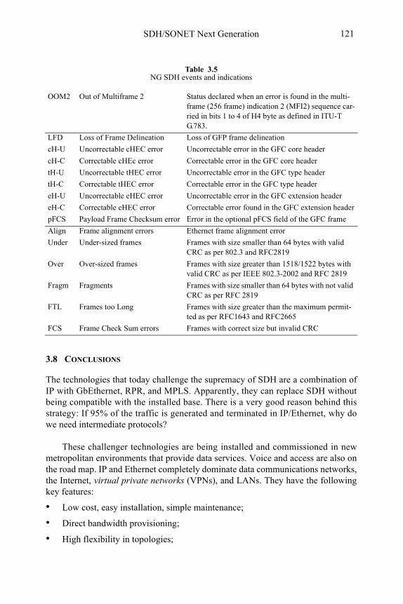
SDH/SONET Next Generation 121
3.8 CONCLUSIONS
The technologies that today challenge the supremacy of SDH are a combination of IP with GbEthernet, RPR, and MPLS. Apparently, they can replace SDH without being compatible with the installed base. There is a very good reason behind this strategy: If 95% of the traffic is generated and terminated in IP/Ethernet, why do we need intermediate protocols?
These challenger technologies are being installed and commissioned in new metropolitan environments that provide data services. Voice and access are also on the road map. IP and Ethernet completely dominate data communications networks, the Internet, virtual private networks (VPNs), and LANs. They have the following key features:
• Low cost, easy installation, simple maintenance;
• Direct bandwidth provisioning;
• High flexibility in topologies;
OOM2 Out of Multiframe 2 Status declared when an error is found in the multi-frame (256 frame) indication 2 (MFI2) sequence car-ried in bits 1 to 4 of H4 byte as defined in ITU-T G.783.
LFD Loss of Frame Delineation Loss of GFP frame delineation
cH-U Uncorrectable cHEC error Uncorrectable error in the GFC core header
cH-C Correctable cHEc error Correctable error in the GFC core header
tH-U Uncorrectable tHEC error Uncorrectable error in the GFC type header
tH-C Correctable tHEC error Correctable error in the GFC type header
eH-U Uncorrectable eHEC error Uncorrectable error in the GFC extension header
eH-C Correctable eHEC error Correctable error found in the GFC extension header
pFCS Payload Frame Checksum error Error in the optional pFCS field of the GFC frame
Align Frame alignment errors Ethernet frame alignment error
Under Under-sized frames Frames with size smaller than 64 bytes with valid CRC as per 802.3 and RFC2819
Over Over-sized frames Frames with size greater than 1518/1522 bytes with valid CRC as per IEEE 802.3-2002 and RFC 2819
Fragm Fragments Frames with size smaller than 64 bytes with not valid CRC as per RFC 2819
FTL Frames too Long Frames with size greater than the maximum permit-ted as per RFC1643 and RFC2665
FCS Frame Check Sum errors Frames with correct size but invalid CRC
Table 3.5NG SDH events and indications
Migration to Next Generation SDH122
• Scalability in terms of speed and distance.
Unfortunately, some weaknesses (poor management, lack of quality of service, jitter) still limit their application. However, they are moving in two directions:
1. Optical integration to improve performance and resilience. Several solutions have already been developed, with different levels of acceptance, including EoFiber, EoRPR, EoDWDM, and EoS.
2. IP delayering process to provide quality voice and video as well.
Originally designed for telephony services, SDH has dominated the transmis-sion networks of the world since the early 90s, providing high-quality connections. Their key features and benefits are:
• Comprehensive OAM functions;
• Resilience mechanisms to configure fault-tolerant architectures;
• Performance monitoring and hierarchical event control;
• Synchronization, reducing jitter and wander below limits set in standards.
Today, SDH continues improving its granularity and flexibility for data trans-port by means of such new standards as GFP, Virtual Concatenation, and LCAS. In addition a new higher hierarchy, STM-256/OC-768, is ready to be installed.
The answer to the dilemma between the circuit-based and the packet-based ap-proaches is a new generation of multiservice nodes providing the best of both worlds by a process of convergence (see Figure 3.2). They integrate all the remote access, routing, and switching capabilities into the same pipe. In addition, there are:
• Network interfaces: GbEthernet, STM-n/OC-m, and DWDM;
• Protocols: MPLS, ATM, IP, and VLAN;
• Client interfaces: TDM, VC, VT, Ethernet, ATM, IP, and DVB.
They maintain resilience based on protection schemes, while adding a new resil-ience strategy based on LCAS which is far more interesting for data packet net-works. Any topology is possible, be it linear, UPSR, BLSR, or mesh. The definite proof of convergence will be if the next rate defined for Ethernet is 40 Gbps rather than 100 Gbps.
Selected Bibliography
• ITU-T Rec. G.707/Y.1305, Network node interface for the synchronous digital hierarchy (SDH), Dec 2003.
SDH/SONET Next Generation 123
• ITU-T Rec. G.7041/Y.1303, Generic framing procedure (GPF), Dec. 2003.
• ITU-T Rec. G.7042/Y.1305, Link capacity adjustment scheme (LCAS) for virtual concatenated sig-nals, Feb 2004.
• Jose Caballero, et al. Installation and Maintenance of SDH/SONET, ATM, xDSL and Synchronization Networks, Artech House Aug. 2003
• IEEE 802.3-2002, Carrier Sense Multiple Access with Collision Detection (CSMA/CD) access method and physical layer specifications, March 2002
• Enrique Hernández Valencia, “The Generic Framing Procedure (GFP),” IEEE Communications Mag-azine, May 2002.
• ISO/IEC 3309 Information Technology - Telecommunications and Information eXchange Between Systems - High-level Data Link Control (HDLC) Procedures - Frame Structure, 1993.
• ITU-T Rec. X.85/Y.1321, IP over SDH using LAPS, Oct. 2000.
• ITU-T Rec. G.803, Architecture of transport networks based on the SDH, March 2000.
• ITU-T Rec. G.841, Types and characteristics of SDH network protection architectures. Oct. 1998.
• ITU-T Rec. G.957, Optical interfaces for equipment and systems relating to the SDH, June 1999.
• MEF, “Metro Ethernet Networks - A Technical Overview” - White paper, http://www.metroethernet-forum.org/, December 2003
• MEF, “Metro Ethernet Services - A Technical Overview” - White paper, http://www.metroethernetfo-rum.org/, January 2004
• G. Churuvolu, A. Ge, D. Elie-Dit-Cosaque, M. Ali, and J. Rouyer, “Issues and Approaches on Extending Ethernet Beyond LANs”, IEEE Communications Magazine, March 2004, pp. 80-86
• E. Hernandez-Valencia, G. Rosenfeld, “The Building Blocks of a Data-Aware Transport Network: Deploying Viable Ethernet and Virtual Wire Services via Multiservice ADMs”, IEEE Communica-tions Magazine, March 2004, pp. 104-111
• P. Bonenfant, A. Rodriguez-Moral, “Generic Framing Procedure (GFP): The Catalyst for Efficient Data over Transport”, IEEE Communications Magazine, May 2002, pp. 72-79
• S. Gorshe, T. Wilson, “Transparent Generic Framing Procedure (GFP): A Protocol for Efficient Transport of Block-Coded Data through SONET/SDH Networks”, IEEE Communications Magazine, May 2002, pp. 88-94

Migration to Next Generation SDH124
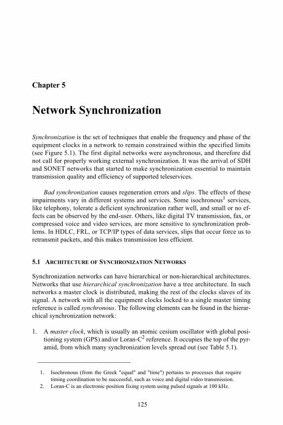
125
Chapter 5
Network Synchronization
Synchronization is the set of techniques that enable the frequency and phase of the equipment clocks in a network to remain constrained within the specified limits (see Figure 5.1). The first digital networks were asynchronous, and therefore did not call for properly working external synchronization. It was the arrival of SDH and SONET networks that started to make synchronization essential to maintain transmission quality and efficiency of supported teleservices.
Bad synchronization causes regeneration errors and slips. The effects of these impairments vary in different systems and services. Some isochronous1 services, like telephony, tolerate a deficient synchronization rather well, and small or no ef-fects can be observed by the end-user. Others, like digital TV transmission, fax, or compressed voice and video services, are more sensitive to synchronization prob-lems. In HDLC, FRL, or TCP/IP types of data services, slips that occur force us to retransmit packets, and this makes transmission less efficient.
5.1 ARCHITECTURE OF SYNCHRONIZATION NETWORKS
Synchronization networks can have hierarchical or non-hierarchical architectures. Networks that use hierarchical synchronization have a tree architecture. In such networks a master clock is distributed, making the rest of the clocks slaves of its signal. A network with all the equipment clocks locked to a single master timing reference is called synchronous. The following elements can be found in the hierar-chical synchronization network:
1. A master clock, which is usually an atomic cesium oscillator with global posi-tioning system (GPS) and/or Loran-C2 reference. It occupies the top of the pyr-amid, from which many synchronization levels spread out (see Table 5.1).
1. Isochronous (from the Greek "equal" and "time") pertains to processes that require timing coordination to be successful, such as voice and digital video transmission.
2. Loran-C is an electronic position fixing system using pulsed signals at 100 kHz.
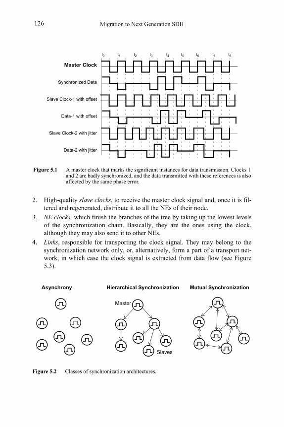
Migration to Next Generation SDH126
2. High-quality slave clocks, to receive the master clock signal and, once it is fil-tered and regenerated, distribute it to all the NEs of their node.
3. NE clocks, which finish the branches of the tree by taking up the lowest levels of the synchronization chain. Basically, they are the ones using the clock, although they may also send it to other NEs.
4. Links, responsible for transporting the clock signal. They may belong to the synchronization network only, or, alternatively, form a part of a transport net-work, in which case the clock signal is extracted from data flow (see Figure 5.3)
Figure 5.2 Classes of synchronization architectures.
Master
Asynchrony Hierarchical Synchronization Mutual Synchronization
Slaves
.
Figure 5.1 A master clock that marks the significant instances for data transmission. Clocks 1 and 2 are badly synchronized, and the data transmitted with these references is also affected by the same phase error.
Master Clock
Slave Clock-1 with offset
Data-1 with offset
Slave Clock-2 with jitter
Data-2 with jitter
Synchronized Data
t1 t2 t3 t4t0 t6 t7 t8t5
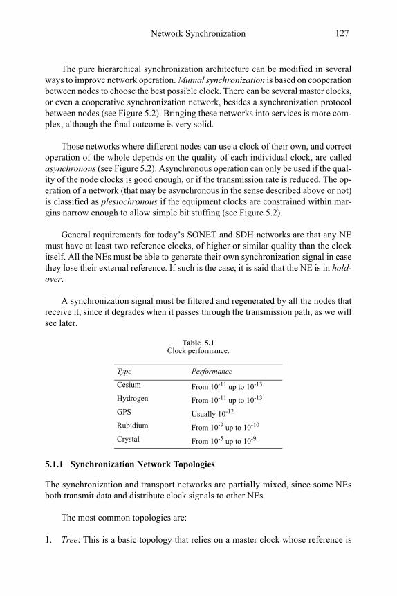
Network Synchronization 127
The pure hierarchical synchronization architecture can be modified in several ways to improve network operation. Mutual synchronization is based on cooperation between nodes to choose the best possible clock. There can be several master clocks, or even a cooperative synchronization network, besides a synchronization protocol between nodes (see Figure 5.2). Bringing these networks into services is more com-plex, although the final outcome is very solid.
Those networks where different nodes can use a clock of their own, and correct operation of the whole depends on the quality of each individual clock, are called asynchronous (see Figure 5.2). Asynchronous operation can only be used if the qual-ity of the node clocks is good enough, or if the transmission rate is reduced. The op-eration of a network (that may be asynchronous in the sense described above or not) is classified as plesiochronous if the equipment clocks are constrained within mar-gins narrow enough to allow simple bit stuffing (see Figure 5.2).
General requirements for today’s SONET and SDH networks are that any NE must have at least two reference clocks, of higher or similar quality than the clock itself. All the NEs must be able to generate their own synchronization signal in case they lose their external reference. If such is the case, it is said that the NE is in hold-over.
A synchronization signal must be filtered and regenerated by all the nodes that receive it, since it degrades when it passes through the transmission path, as we will see later.
5.1.1 Synchronization Network Topologies
The synchronization and transport networks are partially mixed, since some NEs both transmit data and distribute clock signals to other NEs.
The most common topologies are:
1. Tree: This is a basic topology that relies on a master clock whose reference is
Table 5.1Clock performance.
Type Performance
Cesium From 10-11 up to 10-13
Hydrogen From 10-11 up to 10-13
GPS Usually 10-12
Rubidium From 10-9 up to 10-10
Crystal From 10-5 up to 10-9
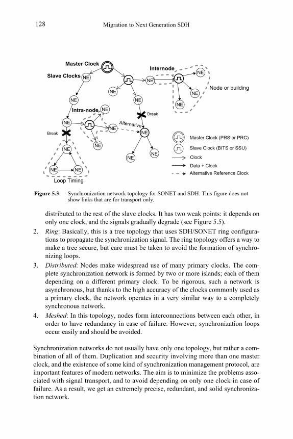
Migration to Next Generation SDH128
distributed to the rest of the slave clocks. It has two weak points: it depends on only one clock, and the signals gradually degrade (see Figure 5.5).
2. Ring: Basically, this is a tree topology that uses SDH/SONET ring configura-tions to propagate the synchronization signal. The ring topology offers a way to make a tree secure, but care must be taken to avoid the formation of synchro-nizing loops.
3. Distributed: Nodes make widespread use of many primary clocks. The com-plete synchronization network is formed by two or more islands; each of them depending on a different primary clock. To be rigorous, such a network is asynchronous, but thanks to the high accuracy of the clocks commonly used as a primary clock, the network operates in a very similar way to a completely synchronous network.
4. Meshed: In this topology, nodes form interconnections between each other, in order to have redundancy in case of failure. However, synchronization loops occur easily and should be avoided.
Synchronization networks do not usually have only one topology, but rather a com-bination of all of them. Duplication and security involving more than one master clock, and the existence of some kind of synchronization management protocol, are important features of modern networks. The aim is to minimize the problems asso-ciated with signal transport, and to avoid depending on only one clock in case of failure. As a result, we get an extremely precise, redundant, and solid synchroniza-tion network.
Clock
Data + Clock
NE
NE
NE
NE
NE
NE
NE
NE
NE
NE
NE
NE
NE
NE
NE
BreakIntra-node
Internode
NE NE
Loop Timing
Master Clock
Figure 5.3 Synchronization network topology for SONET and SDH. This figure does not show links that are for transport only.
Slave Clock (BITS or SSU)
Master Clock (PRS or PRC)
Alternative
NE
Alternative Reference Clock
Slave Clocks
Node or building
Break
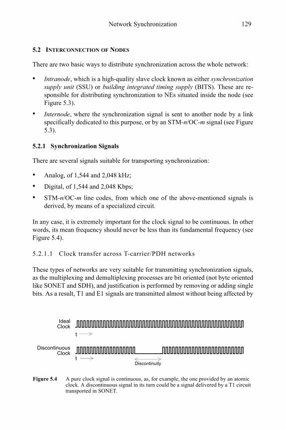
Network Synchronization 129
5.2 INTERCONNECTION OF NODES
Figure 5.4 A pure clock signal is continuous, as, for example, the one provided by an atomic clock. A discontinuous signal in its turn could be a signal delivered by a T1 circuit transported in SONET.
Ideal
t
t
Discontinuous
Discontinuity
Clock
Clock
There are two basic ways to distribute synchronization across the whole network:
• Intranode, which is a high-quality slave clock known as either synchronization supply unit (SSU) or building integrated timing supply (BITS). These are re-sponsible for distributing synchronization to NEs situated inside the node (see Figure 5.3).
• Internode, where the synchronization signal is sent to another node by a link specifically dedicated to this purpose, or by an STM-n/OC-m signal (see Figure 5.3).
5.2.1 Synchronization Signals
There are several signals suitable for transporting synchronization:
• Analog, of 1,544 and 2,048 kHz;
• Digital, of 1,544 and 2,048 Kbps;
• STM-n/OC-m line codes, from which one of the above-mentioned signals is derived, by means of a specialized circuit.
In any case, it is extremely important for the clock signal to be continuous. In other words, its mean frequency should never be less than its fundamental frequency (see Figure 5.4).
5.2.1.1 Clock transfer across T-carrier/PDH networks
These types of networks are very suitable for transmitting synchronization signals, as the multiplexing and demultiplexing processes are bit oriented (not byte oriented like SONET and SDH), and justification is performed by removing or adding single bits. As a result, T1 and E1 signals are transmitted almost without being affected by
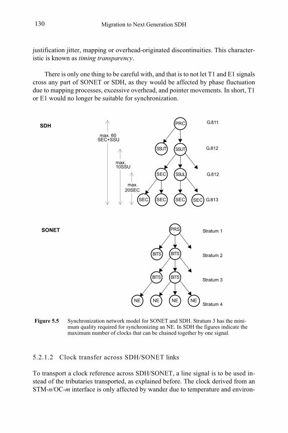
Migration to Next Generation SDH130
justification jitter, mapping or overhead-originated discontinuities. This character-istic is known as timing transparency.
There is only one thing to be careful with, and that is to not let T1 and E1 signals cross any part of SONET or SDH, as they would be affected by phase fluctuation due to mapping processes, excessive overhead, and pointer movements. In short, T1 or E1 would no longer be suitable for synchronization.
5.2.1.2 Clock transfer across SDH/SONET links
To transport a clock reference across SDH/SONET, a line signal is to be used in-stead of the tributaries transported, as explained before. The clock derived from an STM-n/OC-m interface is only affected by wander due to temperature and environ-
NE
Figure 5.5 Synchronization network model for SONET and SDH. Stratum 3 has the mini-mum quality required for synchronizing an NE. In SDH the figures indicate the maximum number of clocks that can be chained together by one signal.
BITS
BITS
NE NE NE
Stratum 1
Stratum 2
Stratum 3
Stratum 4
PRS
BITS
BITS
PRC
SSUT
SSUL
G.813 SEC
max.
max. 60
SEC
SEC
SEC+SSU
20SEC
max.10SSU
SSUT
SEC
G.811
G.812
G.812
SEC
SDH
SONET
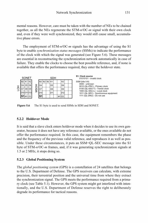
Network Synchronization 131
mental reasons. However, care must be taken with the number of NEs to be chained together, as all the NEs regenerate the STM-n/OC-m signal with their own clock and, even if they were well synchronized, they would still cause small, accumula-tive phase errors.
The employment of STM-n/OC-m signals has the advantage of using the S1 byte to enable synchronization status messages (SSMs) to indicate the performance of the clock with which the signal was generated (see Figure 5.6). These messages are essential in reconstructing the synchronization network automatically in case of failure. They enable the clocks to choose the best possible reference, and, if none is available that offers the performance required, they enter the holdover state.
5.2.2 Holdover Mode
It is said that a slave clock enters holdover mode when it decides to use its own gen-erator, because it does not have any reference available, or the ones available do not offer the performance required. In this case, the equipment remembers the phase and the frequency of the previous valid reference, and reproduces it as well as pos-sible. Under these circumstances, it puts an SSM=QL-SEC message into the S1 byte of STM-n/OC-m frames, and, if it was generating synchronization signals at 1.5 or 2 MHz, it stops doing so.
5.2.3 Global Positioning System
The global positioning system (GPS) is a constellation of 24 satellites that belongs to the U.S. Department of Defense. The GPS receivers can calculate, with extreme precision, their terrestrial position and the universal time from where they extract the synchronization signal. The GPS meets the performance required from a prima-ry clock (see Table 5.1). However, the GPS system might get interfered with inten-tionally, and the U.S. Department of Defense reserves the right to deliberately degrade its performance for tactical reasons.
Figure 5.6 The S1 byte is used to send SSMs in SDH and SONET.
S1: Clock source
0000 - unknown0010 (QL-PRC) - Primary clock0100 (QL-SSU-T) - Transit clock1000 (QL-SSU-L) - Local clock1011 (QL-SEC) - Synchronous equipment1111 (QL-DNU) - Do not use
SSM (bits 5-8)B2 B2 B2 K1 K2
D4 D5 D6
D7 D8 D9
S1 E2
D10 D11 D12
M1
B2 K1 K2
D4 D5 D6
D7 D8 D9
S1 E2
D10 D11 D12
M1
MS
OH
LO
H
SONET SDH 01010101 - invalid clock
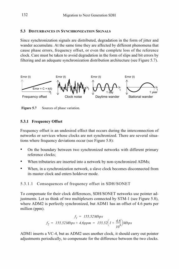
Migration to Next Generation SDH132
5.3 DISTURBANCES IN SYNCHRONIZATION SIGNALS
Since synchronization signals are distributed, degradation in the form of jitter and wander accumulate. At the same time they are affected by different phenomena that cause phase errors, frequency offset, or even the complete loss of the reference clock. Care must be taken to avoid degradation in the form of slips and bit errors by filtering and an adequate synchronization distribution architecture (see Figure 5.7).
5.3.1 Frequency Offset
Frequency offset is an undesired effect that occurs during the interconnection of networks or services whose clocks are not synchronized. There are several situa-tions where frequency deviations occur (see Figure 5.8):
• On the boundary between two synchronized networks with different primary reference clocks;
• When tributaries are inserted into a network by non-synchronized ADMs;
• When, in a synchronization network, a slave clock becomes disconnected from its master clock and enters holdover mode.
5.3.1.1 Consequences of frequency offset in SDH/SONET
To compensate for their clock differences, SDH/SONET networks use pointer ad-justments. Let us think of two multiplexers connected by STM-1 (see Figure 5.8), where ADM2 is perfectly synchronized, but ADM1 has an offset of 4.6 parts per million (ppm).
ADM1 inserts a VC-4, but as ADM2 uses another clock, it should carry out pointer adjustments periodically, to compensate for the difference between the two clocks.
Figure 5.7 Sources of phase variation.
Error (t)
Error = C + k(t)
Error (t)
t
Frequency offset Clock noise
Error (t)
t1 day
Daytime wandert
Error (t)
t1 year
Stational wander
f2 155,52Mbps 4,6ppm+ 155,52 14,6
106
--------+ Mbps= =
f1 155,52Mbps=
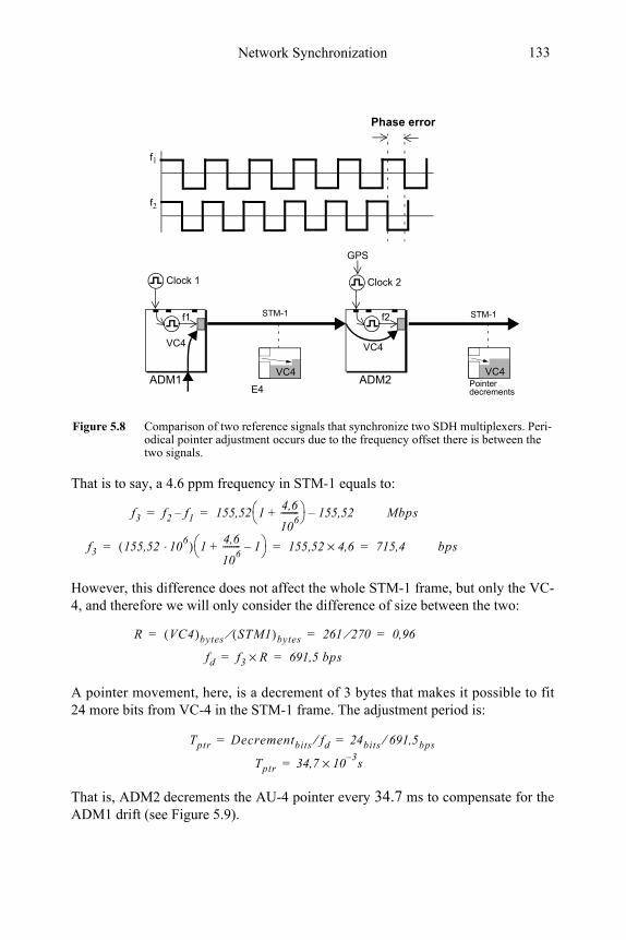
Network Synchronization 133
That is to say, a 4.6 ppm frequency in STM-1 equals to:
However, this difference does not affect the whole STM-1 frame, but only the VC-4, and therefore we will only consider the difference of size between the two:
A pointer movement, here, is a decrement of 3 bytes that makes it possible to fit 24 more bits from VC-4 in the STM-1 frame. The adjustment period is:
That is, ADM2 decrements the AU-4 pointer every 34.7 ms to compensate for the ADM1 drift (see Figure 5.9).
Figure 5.8 Comparison of two reference signals that synchronize two SDH multiplexers. Peri-odical pointer adjustment occurs due to the frequency offset there is between the two signals.
f1
f2
Phase error
STM-1
ADM1
Clock 1
STM-1
Clock 2
GPS
ADM2
VC4
E4
VC4
VC4VC4Pointer decrements
f1 f2
f3 f2 f1– 155,52 14,6
106
--------+ 155,52–= = Mbps
f3 155,52 106⋅( ) 1
4,6
106
-------- 1–+ 155,52 4,6× 715,4= = = bps
R VC4( )bytes STM1( )bytes⁄ 261 270⁄ 0,96= = =
fd f3 R× 691,5 bps= =
Tptr 34,7 103–× s=
Tptr Decrementbits fd⁄ 24bits 691,5bps⁄= =
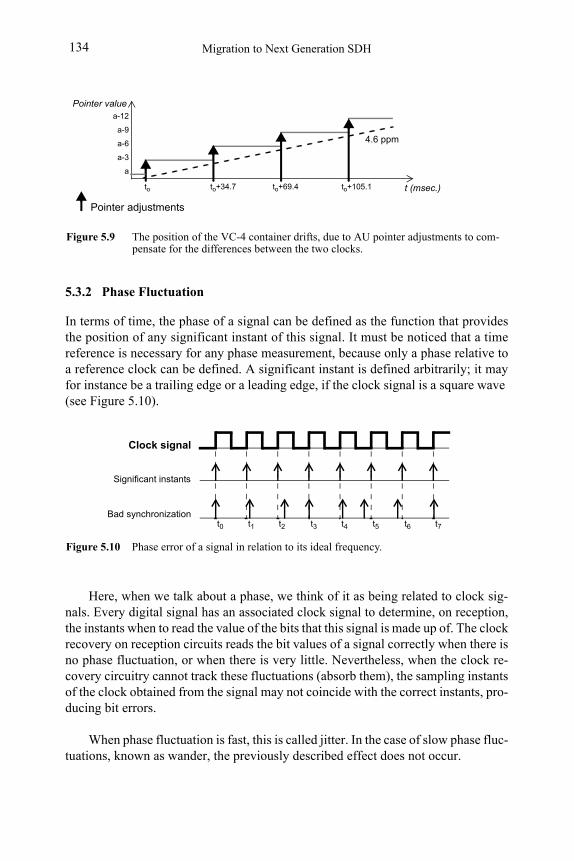
Migration to Next Generation SDH134
5.3.2 Phase Fluctuation
In terms of time, the phase of a signal can be defined as the function that provides the position of any significant instant of this signal. It must be noticed that a time reference is necessary for any phase measurement, because only a phase relative to a reference clock can be defined. A significant instant is defined arbitrarily; it may for instance be a trailing edge or a leading edge, if the clock signal is a square wave (see Figure 5.10).
Here, when we talk about a phase, we think of it as being related to clock sig-nals. Every digital signal has an associated clock signal to determine, on reception, the instants when to read the value of the bits that this signal is made up of. The clock recovery on reception circuits reads the bit values of a signal correctly when there is no phase fluctuation, or when there is very little. Nevertheless, when the clock re-covery circuitry cannot track these fluctuations (absorb them), the sampling instants of the clock obtained from the signal may not coincide with the correct instants, pro-ducing bit errors.
When phase fluctuation is fast, this is called jitter. In the case of slow phase fluc-tuations, known as wander, the previously described effect does not occur.
Figure 5.9 The position of the VC-4 container drifts, due to AU pointer adjustments to com-pensate for the differences between the two clocks.
t (msec.)
4.6 ppm
Pointer adjustments
a
a-3
a-6
a-9
a-12
to
Pointer value
to+34.7 to+69.4 to+105.1
Figure 5.10 Phase error of a signal in relation to its ideal frequency.
Clock signal
Significant instants
t0 t1 t2 t3 t4 t5 t6 t7
Bad synchronization
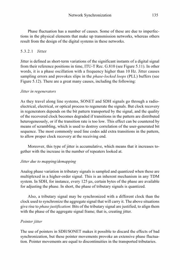
Network Synchronization 135
Phase fluctuation has a number of causes. Some of these are due to imperfec-tions in the physical elements that make up transmission networks, whereas others result from the design of the digital systems in these networks.
5.3.2.1 Jitter
Jitter is defined as short-term variations of the significant instants of a digital signal from their reference positions in time, ITU-T Rec. G.810 (see Figure 5.11). In other words, it is a phase oscillation with a frequency higher than 10 Hz. Jitter causes sampling errors and provokes slips in the phase-locked loops (PLL) buffers (see Figure 5.12). There are a great many causes, including the following:
Jitter in regenerators
As they travel along line systems, SONET and SDH signals go through a radio-electrical, electrical, or optical process to regenerate the signals. But clock recovery in regenerators depends on the bit pattern transported by the signal, and the quality of the recovered clock becomes degraded if transitions in the pattern are distributed heterogeneously, or if the transition rate is too low. This effect can be countered by means of scrambling, which is used to destroy correlation of the user-generated bit sequence. The most commonly used line codes add extra transitions in the pattern, to allow proper clock recovery at the receiving end.
Moreover, this type of jitter is accumulative, which means that it increases to-gether with the increase in the number of repeaters looked at.
Jitter due to mapping/demapping
Analog phase variation in tributary signals is sampled and quantized when these are multiplexed in a higher-order signal. This is an inherent mechanism in any TDM system. In SDH, for instance, every 125 μs, certain bytes of the phase are available for adjusting the phase. In short, the phase of tributary signals is quantized.
Also, a tributary signal may be synchronized with a different clock than the clock used to synchronize the aggregate signal that will carry it. The above situations give rise to phase justification: Bits of the tributary signal are justified, to align them with the phase of the aggregate signal frame; that is, creating jitter.
Pointer jitter
The use of pointers in SDH/SONET makes it possible to discard the effects of bad synchronization, but these pointer movements provoke an extensive phase fluctua-tion. Pointer movements are equal to discontinuities in the transported tributaries.
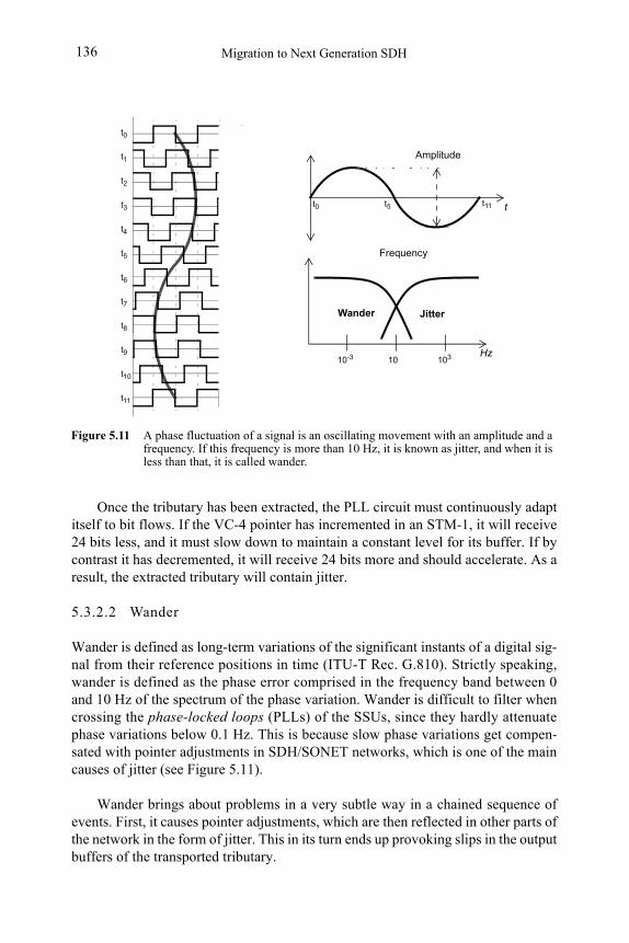
Migration to Next Generation SDH136
Once the tributary has been extracted, the PLL circuit must continuously adapt itself to bit flows. If the VC-4 pointer has incremented in an STM-1, it will receive 24 bits less, and it must slow down to maintain a constant level for its buffer. If by contrast it has decremented, it will receive 24 bits more and should accelerate. As a result, the extracted tributary will contain jitter.
5.3.2.2 Wander
Wander is defined as long-term variations of the significant instants of a digital sig-nal from their reference positions in time (ITU-T Rec. G.810). Strictly speaking, wander is defined as the phase error comprised in the frequency band between 0 and 10 Hz of the spectrum of the phase variation. Wander is difficult to filter whencrossing the phase-locked loops (PLLs) of the SSUs, since they hardly attenuate phase variations below 0.1 Hz. This is because slow phase variations get compen-sated with pointer adjustments in SDH/SONET networks, which is one of the main causes of jitter (see Figure 5.11).
Wander brings about problems in a very subtle way in a chained sequence of events. First, it causes pointer adjustments, which are then reflected in other parts of the network in the form of jitter. This in its turn ends up provoking slips in the output buffers of the transported tributary.
t0 t11t5
Figure 5.11 A phase fluctuation of a signal is an oscillating movement with an amplitude and a frequency. If this frequency is more than 10 Hz, it is known as jitter, and when it is less than that, it is called wander.
10
Wander Jitter
t0
t1
t2
t3
t4
t5
t6
t7
t8
t9
t10
t11
Frequency
10310-3 Hz
Amplitude
t
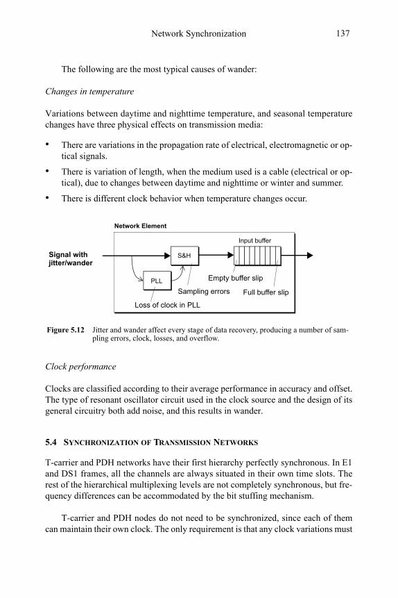
Network Synchronization 137
The following are the most typical causes of wander:
Changes in temperature
Variations between daytime and nighttime temperature, and seasonal temperature changes have three physical effects on transmission media:
• There are variations in the propagation rate of electrical, electromagnetic or op-tical signals.
• There is variation of length, when the medium used is a cable (electrical or op-tical), due to changes between daytime and nighttime or winter and summer.
• There is different clock behavior when temperature changes occur.
Clock performance
Clocks are classified according to their average performance in accuracy and offset. The type of resonant oscillator circuit used in the clock source and the design of its general circuitry both add noise, and this results in wander.
5.4 SYNCHRONIZATION OF TRANSMISSION NETWORKS
T-carrier and PDH networks have their first hierarchy perfectly synchronous. In E1 and DS1 frames, all the channels are always situated in their own time slots. The rest of the hierarchical multiplexing levels are not completely synchronous, but fre-quency differences can be accommodated by the bit stuffing mechanism.
T-carrier and PDH nodes do not need to be synchronized, since each of them can maintain their own clock. The only requirement is that any clock variations must
Loss of clock in PLL
Sampling errors
Input buffer
Empty buffer slip
S&H
PLL
Signal with
Figure 5.12 Jitter and wander affect every stage of data recovery, producing a number of sam-pling errors, clock, losses, and overflow.
Full buffer slip
Network Element
jitter/wander
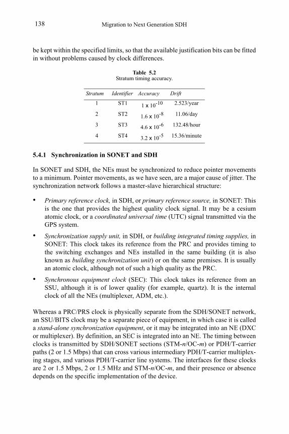
Migration to Next Generation SDH138
be kept within the specified limits, so that the available justification bits can be fitted in without problems caused by clock differences.
5.4.1 Synchronization in SONET and SDH
In SONET and SDH, the NEs must be synchronized to reduce pointer movements to a minimum. Pointer movements, as we have seen, are a major cause of jitter. The synchronization network follows a master-slave hierarchical structure:
• Primary reference clock, in SDH, or primary reference source, in SONET: This is the one that provides the highest quality clock signal. It may be a cesium atomic clock, or a coordinated universal time (UTC) signal transmitted via the GPS system.
• Synchronization supply unit, in SDH, or building integrated timing supplies, in SONET: This clock takes its reference from the PRC and provides timing to the switching exchanges and NEs installed in the same building (it is also known as building synchronization unit) or on the same premises. It is usually an atomic clock, although not of such a high quality as the PRC.
• Synchronous equipment clock (SEC): This clock takes its reference from an SSU, although it is of lower quality (for example, quartz). It is the internal clock of all the NEs (multiplexer, ADM, etc.).
Whereas a PRC/PRS clock is physically separate from the SDH/SONET network, an SSU/BITS clock may be a separate piece of equipment, in which case it is called a stand-alone synchronization equipment, or it may be integrated into an NE (DXC or multiplexer). By definition, an SEC is integrated into an NE. The timing between clocks is transmitted by SDH/SONET sections (STM-n/OC-m) or PDH/T-carrier paths (2 or 1.5 Mbps) that can cross various intermediary PDH/T-carrier multiplex-ing stages, and various PDH/T-carrier line systems. The interfaces for these clocks are 2 or 1.5 Mbps, 2 or 1.5 MHz and STM-n/OC-m, and their presence or absence depends on the specific implementation of the device.
Table 5.2Stratum timing accuracy.
Stratum Identifier Accuracy Drift
1 ST1 1 x 10⁻¹⁰ 2.523/year
2 ST2 1.6 x 10⁻⁸ 11.06/day
3 ST3 4.6 x 10⁻⁶ 132.48/hour
4 ST4 3.2 x 10⁻⁵ 15.36/minute
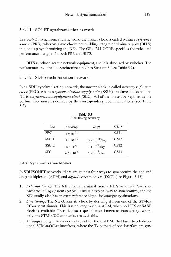
Network Synchronization 139
5.4.1.1 SONET synchronization network
In a SONET synchronization network, the master clock is called primary reference source (PRS), whereas slave clocks are building integrated timing supply (BITS) that end up synchronizing the NEs. The GR-1244-CORE specifies the rules and performance margins for both PRS and BITS.
BITS synchronizes the network equipment, and it is also used by switches. The performance required to synchronize a node is Stratum 3 (see Table 5.2).
5.4.1.2 SDH synchronization network
In an SDH synchronization network, the master clock is called primary reference clock (PRC), whereas synchronization supply units (SSUs) are slave clocks and the NE is a synchronous equipment clock (SEC). All of them must be kept inside the performance margins defined by the corresponding recommendations (see Table 5.3).
5.4.2 Synchronization Models
In SDH/SONET networks, there are at least four ways to synchronize the add and drop multiplexers (ADM) and digital cross connects (DXC) (see Figure 5.13):
1. External timing: The NE obtains its signal from a BITS or stand-alone syn-chronization equipment (SASE). This is a typical way to synchronize, and the NE usually also has an extra reference signal for emergency situations.
2. Line timing: The NE obtains its clock by deriving it from one of the STM-n/OC-m input signals. This is used very much in ADM, when no BITS or SASE clock is available. There is also a special case, known as loop timing, where only one STM-n/OC-m interface is available.
3. Through timing: This mode is typical for those ADMs that have two bidirec-tional STM-n/OC-m interfaces, where the Tx outputs of one interface are syn-
Table 5.3SDH timing accuracy.
Use Accuracy Drift ITU-T
PRC 1 x 10-11 — G.811
SSU-T 5 x 10⁻¹⁰ 10 x 10-10/day G.812
SSU-L 5 x 10⁻⁸ 3 x 10⁻⁷/day G.812
SEC 4.6 x 10⁻⁶ 5 x 10⁻⁷/day G.813
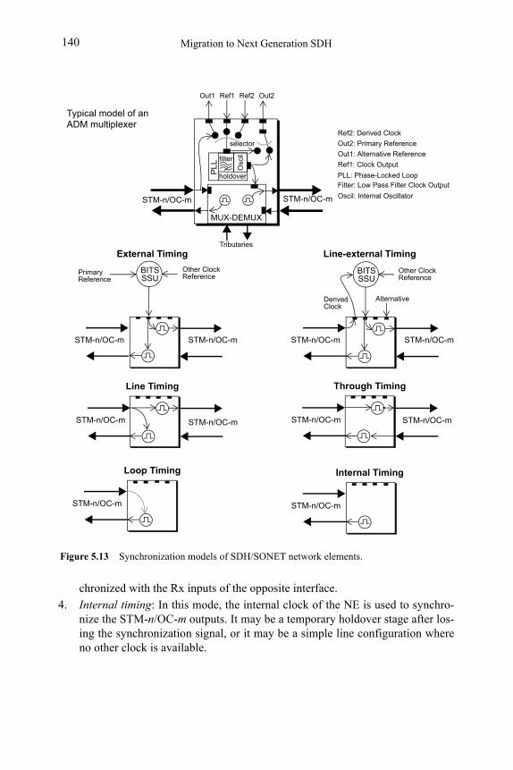
Migration to Next Generation SDH140
chronized with the Rx inputs of the opposite interface.
4. Internal timing: In this mode, the internal clock of the NE is used to synchro-nize the STM-n/OC-m outputs. It may be a temporary holdover stage after los-ing the synchronization signal, or it may be a simple line configuration where no other clock is available.
Figure 5.13 Synchronization models of SDH/SONET network elements.
STM-n/OC-m STM-n/OC-m
Primary Reference
External Timing
STM-n/OC-m STM-n/OC-m
Other ClockReference
Alternative
Line-external Timing
DerivedClock
BITSSSU
STM-n/OC-m
Other ClockReference
BITSSSU
STM-n/OC-m
Line Timing
STM-n/OC-m STM-n/OC-mSTM-n/OC-m
STM-n/OC-m
Internal Timing
holdover
selector
MUX-DEMUX
STM-n/OC-m STM-n/OC-m
PL
L
Out1 Ref1 Ref2 Out2
Out1: Alternative Reference
Ref1: Clock Output
Ref2: Derived Clock
Out2: Primary Reference
PLL: Phase-Locked Loop
Tributaries O
scil
Filter: Low Pass Filter Clock Output
Oscil: Internal Oscillator
Typical model of anADM multiplexer
Through Timing
Loop Timing
filter
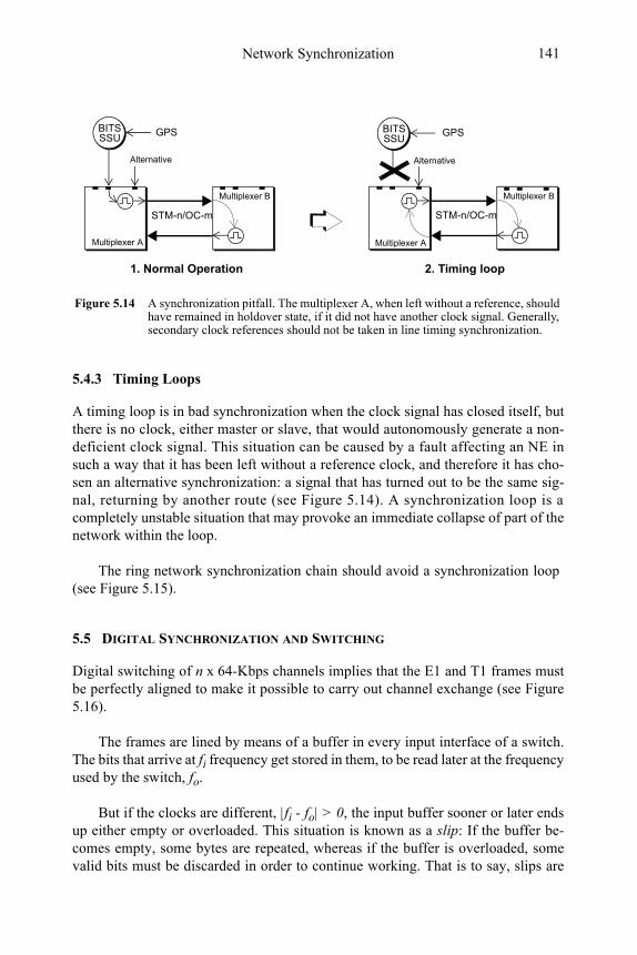
Network Synchronization 141
5.4.3 Timing Loops
A timing loop is in bad synchronization when the clock signal has closed itself, but there is no clock, either master or slave, that would autonomously generate a non-deficient clock signal. This situation can be caused by a fault affecting an NE in such a way that it has been left without a reference clock, and therefore it has cho-sen an alternative synchronization: a signal that has turned out to be the same sig-nal, returning by another route (see Figure 5.14). A synchronization loop is a completely unstable situation that may provoke an immediate collapse of part of the network within the loop.
The ring network synchronization chain should avoid a synchronization loop (see Figure 5.15).
5.5 DIGITAL SYNCHRONIZATION AND SWITCHING
Digital switching of n x 64-Kbps channels implies that the E1 and T1 frames must be perfectly aligned to make it possible to carry out channel exchange (see Figure 5.16).
The frames are lined by means of a buffer in every input interface of a switch. The bits that arrive at fi frequency get stored in them, to be read later at the frequency used by the switch, fo.
But if the clocks are different, |fi - fo| > 0, the input buffer sooner or later ends up either empty or overloaded. This situation is known as a slip: If the buffer be-comes empty, some bytes are repeated, whereas if the buffer is overloaded, some valid bits must be discarded in order to continue working. That is to say, slips are
Figure 5.14 A synchronization pitfall. The multiplexer A, when left without a reference, should have remained in holdover state, if it did not have another clock signal. Generally, secondary clock references should not be taken in line timing synchronization.
STM-n/OC-m
Multiplexer A
Multiplexer B
STM-n/OC-m
Multiplexer A
BITSSSU
Multiplexer B
1. Normal Operation 2. Timing loop
BITSSSU
Alternative Alternative
GPS GPS
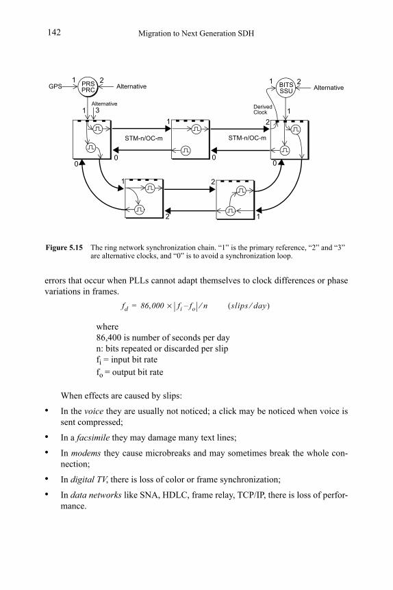
Migration to Next Generation SDH142
errors that occur when PLLs cannot adapt themselves to clock differences or phase variations in frames.
where 86,400 is number of seconds per day n: bits repeated or discarded per slip fi = input bit rate fo = output bit rate
When effects are caused by slips:
• In the voice they are usually not noticed; a click may be noticed when voice is sent compressed;
• In a facsimile they may damage many text lines;
• In modems they cause microbreaks and may sometimes break the whole con-nection;
• In digital TV, there is loss of color or frame synchronization;
• In data networks like SNA, HDLC, frame relay, TCP/IP, there is loss of perfor-mance.
STM-n/OC-m
PRSPRC
Alternative
Alternative
Figure 5.15 The ring network synchronization chain. “1” is the primary reference, “2” and “3” are alternative clocks, and “0” is to avoid a synchronization loop.
0
STM-n/OC-m
DerivedClock
BITSSSU
1
2
3
0
1
1 2
1
0
2
1
0
GPS1 2
Alternative21
fd 86 000, fi fo– n⁄×= slips day⁄( )

Network Synchronization 143
5.6 SSU IN A SYNCHRONIZATION NETWORK
The SSU is in charge of synchronizing all the NEs of its node. It has many alterna-tive clock inputs or references, to confront possible clock signal losses. It may be integrated in an ADM or CXC multiplexer, or it can be a stand-alone equipment, in which case it is known as SASE (see Figure 5.17).
Figure 5.16 Synchronization of two digital centrals: (a) by signal derived from the PDH chain; (b) by PDH and SASE chain; and (c) across SDH network.
E4
Switch A
Clock
E1
Switch B
Multiplexer A Multiplexer BE1
E4
Switch A
SASE
E1
Switch B
Multiplexer A Multiplexer BE1
Other clockReference
DerivedClock
BITSSSU
Primary Reference
Switch A
SASE
E1
Primary Reference
STM-n/OC-m
BITSSSU
Switch B
(a)
(b)
(c)
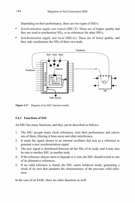
Migration to Next Generation SDH144
Depending on their performance, there are two types of SSUs:
• Synchronization supply unit transit (SSU-T): These are of higher quality and they are used to synchronize NEs, or as references for other SSUs.
• Synchronization supply unit local (SSU-L): These are of lower quality, and they only synchronize the NEs of their own node.
5.6.1 Functions of SSU
An SSU has many functions, and they can be described as follows:
1. The SSU accepts many clock references, tests their performance and selects one of them, filtering it from noise and other interference.
2. It sends the signal chosen to an internal oscillator that acts as a reference to generate a new synchronization signal.
3. The new signal is distributed between all the NEs of its node, and it may also be sent to another SSU in another node.
4. If the reference chosen starts to degrade or is lost, the SSU should switch to one of its alternative references.
5. If no valid reference is found, the SSU enters holdover mode, generating a clock of its own that emulates the characteristics of the previous valid refer-ence.
In the case of an SASE, there are other functions as well:
Figure 5.17 Diagram of an SSU function model.
holdover
filter
Ref1 Ref2 Ref2
TMN control
NE
mon
itori
ng
Feedback selector
NE
Feedback

Network Synchronization 145
1. It monitors the synchronization status of the NEs of its node by means of return links.
2. It continuously informs the TMN control level of both its own synchronization status and that of the NEs of its node.
Selected Bibliography
• ITU-T Rec. G.703, Physical/electrical characteristics of hierarchical digital interfaces.
• ITU-T Rec. G.781, Synchronization layer functions.
• ITU-T Rec. G.783, Characteristics of synchronous digital hierarchy (SDH) equipment functional blocks.
• ITU-T Rec. G.803, Architecture of transport networks based on the synchronous digital hierarchy (SDH).
• ITU-T Rec. G.810, Definitions and terminology for synchronization networks.
• ITU-T Rec. G.811, Timing characteristics of primary reference clocks.
• ITU-T Rec. G.812, Timing requirements of slave clocks suitable for use as node clocks in synchroni-zation networks.
• ITU-T Rec. G.813, Timing characteristics of SDH equipment slave clocks (SEC).
• ITU-T Rec. G.822, Controlled slip rate objectives on an international digital connection.
• ITU-T Rec. G.823, The control of jitter and wander within digital networks which are based on the 2048 kbit/s hierarchy.
• ITU-T Rec. G.824, The control of jitter and wander within digital networks which are based on the 1544 kbit/s hierarchy.
• ITU-T Rec. G.825, The control of jitter and wander within digital networks which are based on the synchronous digital hierarchy (SDH).
• ITU-T Rec.G.8251, The control of jitter and wander within the optical transport network (OTN).
• José M. Caballero and Andreu Guimerà, Jerarquías Digitales de Multiplexión, PDH y SDH, Sincron-ización de Redes, L&M Data Communications 2001.

Migration to Next Generation SDH146
147
Index
AA-bit 23, 24, 28Add and drop multiplexer (ADM) 41, 139Administrative unit (AU) 45Administrative unit group (AUG) 49AIS 19, 22, 29, 80
AU-AIS 83MS-AIS 82PDH-AIS 83TU-AIS 83
Alarm 75Alarm indication signal (AIS), see AISAlarms
PDH 28SDH 75, 120
Aligning 45, 53Alternate mark inversion (AMI), see Line
codeAnalog signal, see SignalAnomaly 72APS 85Attenuation 3
BBandwidth, see ChannelBER 7, 17, 19, 79B-ISDN 35Bit eight-zero suppression (B8ZS), see Line
codeBit error 16, 134Bit error rate (BER), see BERBit interleaved parity (BIP) 78Bit stuffing, see StuffingBose-Chaudhuri-Hocquengheim (BCH) 79Broadband-ISDN, see B-ISDNBuilding integrated timing supply
(BITS) 129, 139
CCAS 20
LOM 22multiframe alignment signal 21non-multiframe alignment signal 21
signaling multiframe 20C-bit 32
channel signal codes 32parity 31, 32parity framing 32
CCS, see SignalingChannel
2 Kbps 214 Kbps 3056 Kbps 3164 Kbps 14, 29bandwidth 5
definition 7DS0 30E1 15embedded 92
Channel associated signaling, see CASChannel coding 7Channel ID (CID) 103Ci-bit 32Circuit 7, 21
demultiplexing 26signaling circuits 20
Clockmaster 125, 127, 139output signal 26performance of 127, 137PRC 138, 139PRS 138, 139recovery 135sampling 134SEC 138, 139signal 134slave 126transfer
SONET/SDH 130T-carrier/PDH 129
Coded mark inverted (CMI), see Line codeCode-division multiplexing access (CD-
MA), see MultiplexingCommon channel signaling (CCS), see Sig-
naling
Index148
Common management information protocol (CMIP) 91
Communications network, definition 1Concatenation
contiguous 72, 105definition 71, 105virtual 52, 71, 72, 84, 100, 105, 106, 122
Continuous signal, see SignalControl (CTRL) 113CRC 16, 18, 30
advantages of 17multiframe alignment 17
Cross-domain operation 120Crosstalk 6
DDamage 75Data rate, definition 7Defect 75
definition 80Demultiplexing
devices 19Digital cross-connect (DXC) 41, 139Digital signal, see SignalDigital video broadcasting (DVB) 52, 100Discrete signal, see SignalDistortion 3, 4diversification 119DS1-DS3, see FrameDVB 99
EE1, E2, E3, E4 26E-bit 18Enhanced remote defect indication (E-
RDI) 83Error 17, 27, 28
block errors 18digital transmission 6monitoring 17, 18
definition 78PDH events 22, 29See also Bit error
Ethernet 52, 95, 99, 107GbE 64, 121LAPS 52, 100SDH 52
Ethernet Private Line (EPL) 103Events 75, 120
monitoring of 75PDH 22, 29
Extended superframe (ESF) 30, 31
Extension Header Identifier (EXI) 103
FFailure 75Far-end alarm and control (FEAC) 32Far-end block error (FEBE) 32FAS 16, 17, 18, 22, 23, 24, 28, 29F-bit 30FDM 10FDMA 10FEC 79Fiber channel 101Frame
alignment 15alignment signal (FAS), see FASDS1 29, 31, 32
extended superframe 30superframe 30
DS2 32DS3 32E1 15, 19, 21, 141E2 26E3 26E4 26PPP 52STM 54, 55, 57, 69, 70STS 54T1 141 See also Signal
Frame bit, see F-bitFramed-mapped GFP (GFP-F) 103Frame-Mapped GFP 101Frame-Mapped GFP (GFP-F) 103Frequency offset 132
GG.704 19, 20G.7041 52G.7042 52G.707 45, 52G.741 23G.751 24G.810 136Generic framing procedure (GFP) 52, 100Generic framing protocol (GFP) 100Global positioning system (GPS) 131Group Identification (GID) 113
HHigh-density bipolar three zeroes (HDB3),
see Line codeHigher-order path (HP) 43Higher-Order Virtual Concatenation (HO-
Index 149
VCAT) 109Holdover mode 131, 144
definition 127
IImpairment 3, 4
attenuation 3distortion 3, 4noise 3
Indication 75Interface
Q 92X 92
Internode 129Intersymbol interference (ISI) 5Intranode 129ITU-T
G.7041 100G.7042 100, 112, 114G.707 100G.783 120X.86 100
JJ-bit 24, 27, 60Jitter 61, 134
definition 135demapping 135mapping 135pointer 135regenerators 135sampling errors 135SDH 135SONET 135
Justificationphase 135positive 27R-bit 27See also J-bit
LLayer
physical 44seven-layer model 91
Line codeAMI 8, 9, 10, 30B8ZS 9, 30CMI 8, 10HDB3 8, 9, 10
Line section 44Line terminal multiplexer, see LTMUXLink capacity adjustment scheme
(LCAS) 40, 52, 100, 112
Local area network (LAN) 52, 99, 121LOS 19, 28, 32Loss of frame (LOF) 28Loss of multiframe (LOM) 22Lower-order path (LP) 43Lower-order path, see LPLower-Order Virtual Concatenation (LO-
VCAT) 109LTMUX 41
MM.3000 91Management entity 91Management information base (MIB) 92Mapping 45, 53, 55
asynchronous 54, 56, 57synchronous 57
Master clock, see ClockMember Status (MST) 113Metro Internet Forum (MEF) 103MFAS 21Monitoring
errors 78events 75performance 78
MSSP 95MSSPRING 88Multiframe alignment signal (MFAS) 21Multiframe CRC-4 16Multi-Frame Indicator (MFI) 113Multiframe Indicator (MFI) 109Multiple access 10Multiplex section dedicated protection ring
(MSDPRING) 87Multiplex section linear protection
(MSLP) 87Multiplex section overhead, see SOHMultiplex section protection (MSP) 87Multiplex signaling device, see SignalingMultiplexer
See also ADMMultiplexer section (MS) 44Multiplexing 10, 31, 45, 53, 54, 55, 57, 135
CDMA 10definition 10devices 19FDMA 10level 23, 24level 4 24PDMA 11SDMA 11TDMA 10
Index150
types of 10See alsoFDM, TDM, QAM 10
Multiprotocol label switching (MPLS) 121
NNE 40, 78, 138
holdover 127regenerator 40regenerator section 41STE 40
Networkasynchronous 127plesiochronous 127security 83synchronization 128, 139, 143
definition 125synchronous 37See also Topology
Network Management System (NMS) 113Network, elements of 1New data flag (NDF) 61, 63NFAS 19, 20, 28NMFAS 21Node 42, 60, 137
definition 1interconnection 129internode 129intranode 129
Noise 3, 5atmospheric 6crosstalk 6impulse 6intermodulation 6thermal 5
Non-frame alignment signal, see NFASNon-multiframe alignment signal
(NMFAS) 21Non-return to zero (NRZ) 8Nyquist sampling rate, see SamplingNyquist sampling theorem, see Sampling
OOAM functions 91Open systems interconnection (OSI) 91Operation support system (OSS) 91Operation, administration and management
(OAM), see OAM functionsOutput aggregate, see SignalOverhead addition 45Overhead block 46
PPacket
over SDH/SONET (PoS) 52Parity
See also C-bit and ErrorPath
layer, definition 43Path overhead, see POHPath terminal equipment (PTE), see PTEPayload
block 46synchronization 60
PCM 10, 11, 12, 20, 21, 26encoding 13quantization 13sampling 12
PDH 1, 13, 22clock transfer 129events 22, 29hierarchy 25, 26limitations 35multiplexer 27synchronization 137transport of tributaries 53
Performanceclock 127definition 7monitoring of 78
Phasefluctuation 134justification 135quantization 12, 13See also PLL
Plesiochronousdefinition 37synchronization 26See also Signal
Plesiochronous digital hierarchy (PDH), see PDH
PLL 135, 136, 142POH 47, 64, 65, 66
4 bytes 679 bytes 67higher-order 67lower-order 67
Point to point protocol (PPP) 52Pointer 47, 60, 71
adjustment 60decrement 62format 61generation 61increment 62procedures 61
Polarization division multiple access (PD-
Index 151
MA), see MultiplexingPRC, see ClockPrimary reference clock (PRC), see ClockPrimary reference source (PRS), see
Clock 139Protection
1+1 851÷n 85active and passive 85automatic protection switching 85bridge/switch signals 87dedicated and shared 85dual-ended or single-ended 86line 87multiplex section 87revertive or nonrevertive 86ring-switching or span-switching 86subnetwork 89trail or subnetwork 86types of 84, 85unidirectional or bidirectional 85virtual container path 89working or protection resources 85See also Test 84
Pulse 10Pulse code modulation, see PCM
RR-bit 24, 27Regenerator section (RS) 41, 44Regenerator section overhead, see SOHRegenerator, see NERemote alarm indication (RAI) 20Re-Sequence Acknowledge (RS-Ack) 113Resilience
protection 84restoration 84
Resilient packet ring (RPR) 52
SSampling 12, 13, 134
errors 135, 137frequency 12Nyquist rate 12Nyquist sampling rate 12Nyquist sampling theorem 12period 14Shannon sampling theorem 12theorem 12
S-bit 23, 24SDH 35, 52, 60, 61, 64, 69, 73
clock transfer 130
defects 83Ethernet 52events 72, 75, 80, 120
analysis 81layers 42malfunction 72multiplexing map 49performance monitoring 78synchronization 125, 139timing 60
SDH/SONETclock transfer 130pointers, use of 135protection 84restoration 84security 83synchronization 138
models 139, 140SDH/SONET Next Generation 95SEC, see ClockSection overhead, see SOHSection terminating equipment, see NESection, see Regenerator section (RS)Sequence Indicator (SQ) 113Sequence Number (SQ) 109Service bit 24Seven-layer model 91Shannon sampling theorem, see SamplingSignal
analog 2, 129attenuation 3clock signal 129, 134continuous 2delay distortion 5demultiplexing of 23, 29digital 2, 9, 129digitalization of 13discrete 2distortion 4DS1 30, 32DS2 32E1 14, 22, 129, 130information and 1input signal 27line code 8
AMI 8, 10B8ZS 9, 30CMI 8, 10HDB3 8, 9, 10
noise 3, 5output aggregate 27output clock 26
Index152
plesiochronous 22, 26propagation 3significant instant 134spurious 5, 6synchronization 60, 129, 132T1 14, 129, 130tributary 27, 135types of 2See also AIS, LOS, NFAS, Phase, and
SamplingSignaling 20, 21, 31
APS 64CCS 20channel 20circuits 20end-to-end 31in-band 31loss of incoming 21multiframe 21multiplex signaling device 21words 20See also CAS
Simple network management protocol (SNMP) 91
Slave, see ClockSlip 125, 142SOH 67
LOH 69MSOH 54, 67, 69, 80RSOH 44, 54, 67, 80
SONET 35, 39, 73comparison of SDH and 39events 75formats and procedures 45frame structure 46hierarchy 69jitter 135layers 42line section 44malfunction 72multiplexing map 49path layers 43pointers 61section 44synchronization 125virtual concatenation 107virtual tributaries 47See also SDH 72
Space division multiple access (SDMA), see Multiplexing
STM 46, 55, 57, 69, 70 See also Frame
Storage area networks (SAN) 104STS 54, 61, 67, 69, 70, 77, 92STS-1 46Stuffing 24, 27, 32, 45, 127, 137Subnetwork 42, 89Subnetwork connection protection (SNC-
P) 89Superframe (SF) 30, 31Supervision bits 18Switching
digital 141Synchronization
bad 125, 135definition 125digital 141hierarchical 125models 139, 140mutual 127network 128
elements of 125SDH and SONET 128, 130topologies of 127
payload 60PDH 137plesiochronous 26SDH/SONET 138, 139signal 129, 132T-carrier 137
Synchronization status messages (SSM) 131Synchronization supply unit (SSU) 129,
138, 139, 143Synchronous digital hierarchy (SDH), see
SDHSynchronous equipment clock (SEC), see
ClockSynchronous optical network, see SONETSynchronous transmission module (STM),
see STMSynchronous transport signal (STS), see STS
TTandem connection monitoring (TCM) 79T-carrier 1, 13, 26, 138
clock transfer 129hierarchy 14, 29synchronization 137transport of tributaries 53
TDM 10, 14, 27, 135standards 14See also multiplexing
Time slot, see TS0, TS16Timing
Index 153
external 139internal 140line 139through 139transparency 130
Timing loop 141Topology 42
distributed 128hub/star 42meshed 41, 128mixed 41ring 41, 128tree 127
Transmissionaggregate transmission rate 14definition 3digital 8media 1
conductive 2definition 2dielectric 3
quality 18security 83
Transparent GFP 101Transparent GFP (GFP-T) 103Tributary signal, see SignalTributary unit (TU) 45Tributary unit groups (TUG)TS0 16TS16 20, 21, 22
UUnidirectional path switched ring
(UPSR) 90
VVirtual Concatenation (VCAT) 108Virtual container 46, 54, 55
higher-order 55lower-order 55POH 66protection 89
Virtual Container Group (VCG) 108Virtual private network (VPN) 121Virtual tributary path (VT Path) 43VPN 95
WWander 61, 134
clock performance 137definition 136temperature changes 137
XX.86 52

Index154


Many carriers are embracing Next Generation SDH because it answers the challenge of transporting data efficiently, without needing to replace the installed equipment base.
The only change needed to update the network is to replace the edge nodes.The network is then ready to transport Ethernet, PPP, DVB or SAN frames efficiently using Generic Framing Protocol (GFP), Virtual Concatenation (VCAT) and Link Capacity Adjustment Scheme (LCAS).