NG KOK CHUAN - umpir.ump.edu.myumpir.ump.edu.my/id/eprint/1896/1/Ng,_Kok_Chuan_(_CD_4927_).pdfdengan...
24
DEVELOPMENT OF IMPACT STRENGTH MODEL FOR HUMAN SYNTHETIC BONE NG KOK CHUAN Thesis submitted in partial fulfilment of the requirements for the award of the degree of Bachelor of Mechanical Engineering Faculty of Mechanical Engineering UNIVERSITI MALAYSIA PAHANG DECEMBER 2010
Transcript of NG KOK CHUAN - umpir.ump.edu.myumpir.ump.edu.my/id/eprint/1896/1/Ng,_Kok_Chuan_(_CD_4927_).pdfdengan...

DEVELOPMENT OF IMPACT STRENGTH MODEL FOR HUMAN SYNTHETIC BONE
NG KOK CHUAN
Thesis submitted in partial fulfilment of the requirements for the award of the degree of
Bachelor of Mechanical Engineering
Faculty of Mechanical Engineering UNIVERSITI MALAYSIA PAHANG
DECEMBER 2010

ii
SUPERVISOR’S DECLARATION
I hereby declare that I have checked this project and in my opinion, this project is
adequate in terms of scope and quality for the award of the degree of Bachelor of
Mechanical Engineering.
Signature
Name of Supervisor: Dr. DAW THET THET MON
Position: SENIOR LECTURER OF FACULTY OF MECHANICAL
ENGINEERING
Date:

iii
STUDENT’S DECLARATION
I hereby declare that the work in this project is my own except for quotations and
summaries which have been duly acknowledged. The project has not been accepted for
any degree and is not concurently submitted for award of other degree.
Signature
Name: NG KOK CHUAN
ID Number: MA07039
Date:

v
ACKNOWLEDGEMENT
I am grateful and would like to express my sincere gratitude to my supervisor Dr. DAW THET THET MON for her invaluable guidance and constant support in making this thesis. This thesis could not been done without her who not only served as my supervisor but also encourage me throughout the process. I also would like to express very special thanks to the panel member who give valuable comment and suggestion during my project presentation.
My sincere thanks go to all laboratory assistant from Faculty of Mechanical and
Faculty of Manufacturing, Universiti Malaysia Pahang for their teaching and help during the period of my project.
I acknowledge my sincere indebtedness and gratitude to my parents, Mr. NG KIM LING and Mdm. SEOW YOK KUAN for their love and sacrifice throughout my life. They have always supported my dreams. They did a fine job raising me.

vi
ABSTRACT
Due to current demand, the usage of synthetic bone had increased dramatically during these recent years. The main purpose of this project is to develop and analyze the impact strength model for human synthetic bone. The impact test simulation was done in finite element analysis (FEA). The bone model geometry will be designed in Solidwork environment and imported into finite element environment for FEA Finite element analysis will be carried out in MSC. Patran/Marc and Algor respectively. Major input data to FEM were isotropic material model, solid element type (tetrahedral in MSC. Marc and brick in Algor), constraints and impact load. Material properties were taken from literature. The model were validated with published experimental results. Predicted stress-strain response of synthetic bone was agreeable with published report. Based on the analysis results, MSC. Marc model is better than Algor. The result obtained shows the response of synthetic bone towards impact loading.

vii
ABSTRAK
Dengan timbulnya permintaan semasa, permintaan terhadap penggunaan tulang sintetik meningkat secara mendadak sejak beberapa tahun yang lepas. Matlamat utama projek ini adalah untuk mengembangkan dan analisa kekuatan impak modal untuk tulang sintetik manusia. Simulasi ujian impak telah dijalankan dengan menggunakan FEA. Geometri tulang akan dibentuk dalam Solidwork dan diimport ke FEA. FEA akan dijalankan di MSC. Patran/Marc dan Algor. Data utama ke FEM adalah bahan modal isotropik, elemen pepejal (tertra dalam MSC. Marc dan bata dalam Algor, batas dan bban impak Sifat bahan diambil dari sastera. Model tersebut disahkan dengan keputusan experimen yang diterbitkan. Respon stress-tegang yang dijangka adalah dipersetujui dengan laporan yang diterbitkan. Berdasarkan keputusan analisa, modal MSC. Marc adalah lebih baik daripada modal Algor. Keputusan dari analisa menunjukkan penbalasan untuk tulang sintetik manusia terhadap impak.

viii
TABLE OF CONTENTS
Page
SUPERVISOR’S DECLARATION
STUDENT’S DECLARATION
DEDICATION
ii
iii
iv
ACKNOWLEDGEMENTS v
ABSTRACT vi
ABSTRAK vii
TABLE OF CONTENTS viii
LIST OF TABLES xi
LIST OF FIGURES xii
LIST OF SYMBOLS xiv
LIST OF ABBREVIATIONS xv
CHAPTER 1 INTRODUCTION
1.1 Background 1
1.2 Problem Statement 2
1.3
1.5
Objectives
Project Scopes
2
3
CHAPTER 2 LITERATURE REVIEW
2.1 Introduction 4
2.2 Natural Bone 4
2.3 Synthetic Bone Design 5
2.4
2.5
2.6
2.7
Synthetic Bone Material
Impact Load
Lab Based Test
2.6.1 Pendulum Testing
2.6.2 Drop Weight Impact Test
Finite Element Theory
6
7
7
8 9
10

ix
2.8
2.9
2.10
2.11
2.12
Finite Element Software
Analysis of Bone Using Finite Element Method
Impact Theory
Mechanical Properties
Stress-strain Curve
12
12
13
15
18
CHAPTER 3 METHODOLOGY
3.1 Introduction 19
3.2 Flow Chart 20
3.3
Bone Geometry
3.3.1 Design 1 3.3.2 Design 2 3.3.3 Design 3
22
22 22 22
3.4 Model Consideration 23
3.5
3.6
Finite Element Analysis
Finite Element Formulation
23
27
CHAPTER 4 RESULTS AND DISCUSSION
4.1 Introduction 29
4.2
Computer Aided Model
4.2.1 Design 1 4.2.2 Design 2 4.2.3 Design 3
30
31 32 32
4.3 Pendulum Geometry
4.3.1 Design 1 4.3.2 Design 2
33
34 34
4.4
4.5
4.6
Finite Element Model
Boundary Condition
Analysis Result
4.6.1 Result for MSC. Marc Analysis
35
37
40
41
x
4.7
4.6.2 Result for Algor Analysis
Model Validation
45
48
CHAPTER 5 CONCLUSION AND RECOMMENDATIONS
5.1 Introduction 50
5.2
5.3
Conclusion
Recommendation
50
51
REFERENCES 52
APPENDICES
A Sample Calculation for Stress and Strain 53
B
Data Value for Stress-Strain Graph
54

xi
LIST OF TABLES
Table No. Title Page 3.1 Material properties input value 26 3.2 4.1 4.2
Analysis input data Energy absorbed comparison Stress von Mises comparison
26
48
48
xii
LIST OF FIGURES
Figure No. Title Page 2.1 Bone cross-section 5 2.2 2.3 2.4 2.5 2.6 2.7 2.8 2.9 2.10 2.11 2.12 3.1 3.2 3.3 3.4 4.1 4.2 4.3 4.4 4.5 4.6
Synthetic bone shapes and sizes Synthetic bone microscopic view Analog Charpy Izod Impact Testing Machine FIT 300 Gardner Impact Tester Body with distributed mass Impact load Load applied on free end of cantilever beam Elastic moduli of biological cells and conventional materials Stress-strain response for biological materials Mechanical properties for biological materials Stress-strain of polymer Flow chart Input to FEA Stress-strain curve Graph of the Drucker-Prager yield function Initial geometry Rectangular geometry with porosity Design 2 Design 3 Pendulum real size Design 1 for pendulum
6
7
8
9
10
13
15
16
17
18
18
20
23
24
25
30
31
32
32
33
34

xiii
4.7 4.8 4.9 4.10 4.11 4.12 4.13 4.14 4.15 4.16 4.17 4.18 4.19 4.20 4.21 4.22 4.23 4.24
Design 2 for pendulum Bone meshing with 120% mesh density Pendulum with meshing density 100% Finite element geometry in Algor Finite element model in MSC. Patran Boundary condition for bone Boundary condition for pendulum Complete model in Algor Constrained nodes Displaced nodes Displacement of X component Von Mises stress Von Mises strain Strain energy Displacemetn of X component Von Mises stress Von Mises strain Stress-strain graph
34
35
36
36
37
38
38
39
39
40
41
42
43
44
45
46
47
49

xiv
LIST OF SYMBOLS
� Lagrangian � Kinetic energy � Potential energy m vo E V Pm L I Um
C Ve
Mass Velocity Modulus of elasticity Volume Static force Length Moment of inertia Strain energy Radius Element volume

xv
LIST OF ABBREVIATIONS
FEA Finite element analysis TCP Tricalcium phosphate CAE Computer Aided Engineering CAD Computer Aided Design MSC MacNeal-Schwendler Corporation FEM Finite element method

CHAPTER 1
INTRODUCTION
1.1 BACKGROUND
Almost all livings thing such as animals & humans have bones. Bones are rigid
organs that form part of the skeleton. Bones can produces red and white blood cells and
store minerals. Bones come in a variety of shapes to fit different area of the body as it
provides a frame to keep the body supported. Bone is light in weight yet strong and hard.
There are 206 bones in a human adult body and 270 in a human infant body. Bones serves
as protection for internal organs, such as the skull protecting the brain. Bones combine
and function together to generate and transfer forces so the human body parts can move in
three-dimensional space. Daily activities pose danger to the bones where fracture might
occurs due to various type of loading or force particularly heavier action and more
extreme activities in current society increase the chances for bone fracture (The anatomy
and biology of the human skeleton).
Artificial bone has been developed using bone-like material. It has now played an
important role in bone graft procedures which replace human bone that was lost due to
fracture. There are many researches done to develop one similar to natural bone in effort
to maintain its functions in the human body. For example, artificial bone has porous
structure which allows the growth of blood vessels. Bone properties are important to
withstand different kinds of load especially impact load which is the main cause of
fracture. Impact loading is the dynamic effect on a body and a forcible momentary contact
of another moving body. The bone, however protected is very vulnerable to impact load.
In this regard, knowledge of bone respond to impact load would be useful to improve
bone properties. Unfortunately in literature, only limited study has been done to find out

2
bone respond and these are typical tensile or compression test because of it being an
expensive research and difficult to obtain natural bone test specimen.
In this project, the synthetic bone will be tested to develop impact strength model
since it has similar properties to natural bone. Thus, it can show similar test result and
respond for natural bone. This synthetic bone is commonly used in bone grafting
operation for human. Finite element analysis is carried out to simulate the response of
synthetic bone to impact load.
1.2 PROBLEM STATEMENT
Human are highly exposed to danger that might cause bone fracture especially
from accidents. Accidents can be in form of car crash, fall from higher place, and extreme
sports. As such, demands of bone grafting a process of replacing artificial bone have been
increased. . There are many efforts to create artificial bone which is similar to natural
bone or even a more improved bone property. An important property of artificial bone is
the ability to withstand high impact loading. However the strength of artificial bone to
withstand high impact loading is relatively unknown. The experimental study alone is
expensive due to high cost of the specimen.
1.3 OBJECTIVES
Objectives for this project refer to the mission, purpose, or standard that can be
reasonably achieved within the expected timeframe and with the available resources. The
objectives of this project are:
1. To develop the finite element model that can predict impact strength of human
synthetic bone.
2. To validate finite element model with experiment.
3. To investigate predicted stress-strain responds of synthetic bone under impact
load.

3
1.4 PROJECT SCOPES
The scopes for this project are:
1. Bone geometry will be constructed using Solidwork.
2. Finite element model will be developed in MSC. Patran and Algor.
3. Impact analysis will be carried out in MSC. Marc and Algor.
4. Finite element model will be validated with published experimental result.
5. Stress-strain relationship due to impact load will be plotted in Excel.
Bone model size is scaled down to 12.5% of the actual one to resolve the meshing
problem in finite element model. Two finite element codes are tested to compare its
predictability. Solidworks model is imported to finite element environment for finite
element modeling in MSC. Marc and Algor.

CHAPTER 2
LITERATURE REVIEW
2.1 INTRODUCTION
This chapter will provide the detail description literature review done according
to title of development of impact strength model for human synthetic bone. Literature
regarding any development or experiment about bone properties is useful in this project.
This is includes the bone sizes or shapes available at current market, synthetic bone
material, type of test such as compression and impact, and finite element software
available for analysis.
2.2 NATURAL BONE
The primary tissue of bone, osseous tissue, is a relatively hard and lightweight
composite material, formed mostly of calcium phosphate in the chemical arrangement
termed calcium hydroxylapatite (this is the osseous tissue that gives bones their rigidity).
It has relatively high compressive strength, of about 1800 kg/cm² but poor tensile
strength of 104-121 MPa, meaning it resists pushing forces well, but not pulling forces.
While bone is essentially brittle, it does have a significant degree of elasticity,
contributed chiefly by collagen. All bones consist of living and dead cells embedded in
the mineralized organic matrix that makes up the osseous tissue. Bone is not a
uniformly solid material, but rather has some spaces between its hard elements. The
hard outer layer of bones is composed of compact bone tissue, so-called due to its
minimal gaps and spaces. Its porosity is 5-30%. This tissue gives bones their smooth,
white, and solid appearance, and accounts for 80% of the total bone mass of an adult
skeleton. Compact bone may also be referred to as dense bone. Filling the interior of the

5
bone is the trabecular bone tissue, which is composed of a network of rod- and plate-
like elements that make the overall organ lighter and allow room for blood vessels and
marrow. Trabecular bone accounts for the remaining 20% of total bone mass but has
nearly ten times the surface area of compact bone. Its porosity is 30-90%. If for any
reason there is an alteration in the strain to which the cancellous is subjected, there is a
rearrangement of the trabeculae. The microscopic difference between compact and
cancellous bone is that compact bone consists of haversian sites and osteons, while
cancellous bones do not. Also, bone surrounds blood in the compact bone, while blood
surrounds bone in the cancellous bone. Figure 2.1 shows section through the head of the
femur, showing the cortex, the red bone marrow and a spot of yellow bone marrow. The
white bar represents 1 centimeter. Specimen obtained after total hip replacement surgery,
left hip (Basic Biomechanics).
Figure 2.1: Bone cross-section
Source: Wikimedia Commons
2.3 SYNTHETIC BONE DESIGN
There are many shapes and sizes of synthetic bone design. Available shapes can
be granules, sticks, block, cylinder, and wedge. Sizes can range from 2mm to 14 mm for
regular geometry. Different shapes and sizes serve different purpose or area of
substitute in human bone. Figure 2.2 illustrates synthetic bone size and shapes available
in the market today The synthetic bone is design with fully interconnected pores, having
pore size between 200 to 500um, and mean porosity between 60 to 80 percent to
resemble the real bone.

6
Figure 2.2: Synthetic bone shapes and sizes.
Source: KasiosTCP 2010
2.4 SYNTHETIC BONE MATERIAL
A synthetic bone, so-called TCP as trade name is made of pure β-TCP which is
calcium phosphate molecule similar to the mineral phase of the natural bone. Mode of
operation in curing bone defects is highly bioactive. It undergoes total or partial
resorption and is replace by neoformed natural bone. It is indicated for filling bone
voids or defects of the skeletal system (such as the extremities, spine and the pelvis) that
are not intrinsic to the stability of the bony structure. These defects may be surgically
created osseous defects or osseous defects created from traumatic injury to the bone.
Kasios TCP is a bone graft substitute that resorbs and is replaced with bone during the
healing process.
7
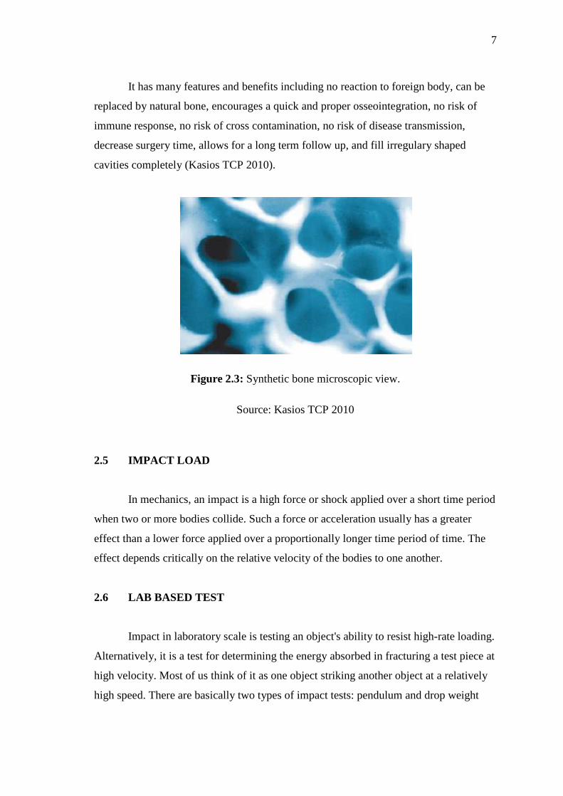
It has many features and benefits including no reaction to foreign body, can be
replaced by natural bone, encourages a quick and proper osseointegration, no risk of
immune response, no risk of cross contamination, no risk of disease transmission,
decrease surgery time, allows for a long term follow up, and fill irregulary shaped
cavities completely (Kasios TCP 2010).
Figure 2.3: Synthetic bone microscopic view.
Source: Kasios TCP 2010
2.5 IMPACT LOAD
In mechanics, an impact is a high force or shock applied over a short time period
when two or more bodies collide. Such a force or acceleration usually has a greater
effect than a lower force applied over a proportionally longer time period of time. The
effect depends critically on the relative velocity of the bodies to one another.
2.6 LAB BASED TEST
Impact in laboratory scale is testing an object's ability to resist high-rate loading.
Alternatively, it is a test for determining the energy absorbed in fracturing a test piece at
high velocity. Most of us think of it as one object striking another object at a relatively
high speed. There are basically two types of impact tests: pendulum and drop weight
8
depending on how the load is applied. It can be further classified as Izod, Charpy, and
tensile impact from view point of specimen geometry and size. (Instron 2010).
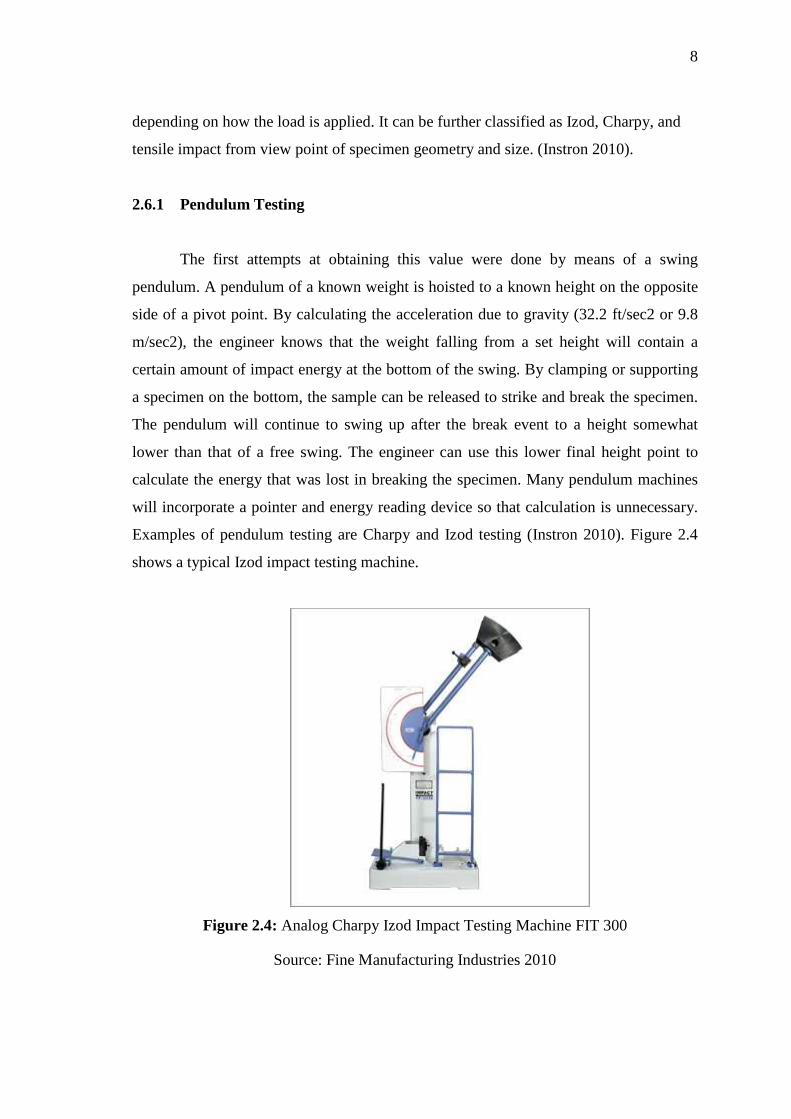
2.6.1 Pendulum Testing
The first attempts at obtaining this value were done by means of a swing
pendulum. A pendulum of a known weight is hoisted to a known height on the opposite
side of a pivot point. By calculating the acceleration due to gravity (32.2 ft/sec2 or 9.8
m/sec2), the engineer knows that the weight falling from a set height will contain a
certain amount of impact energy at the bottom of the swing. By clamping or supporting
a specimen on the bottom, the sample can be released to strike and break the specimen.
The pendulum will continue to swing up after the break event to a height somewhat
lower than that of a free swing. The engineer can use this lower final height point to
calculate the energy that was lost in breaking the specimen. Many pendulum machines
will incorporate a pointer and energy reading device so that calculation is unnecessary.
Examples of pendulum testing are Charpy and Izod testing (Instron 2010). Figure 2.4
shows a typical Izod impact testing machine.
Figure 2.4: Analog Charpy Izod Impact Testing Machine FIT 300
Source: Fine Manufacturing Industries 2010

9
2.6.2 Drop Weight Impact Test
A second method was to drop a weight in a vertical direction, with a tube or rails
to guide it during the "free fall." With the height and weight known, impact energy can
be calculated. In the early days, there was no way to measure impact velocity, so
engineers had to assume no friction in the guide mechanism. Since the falling weight
either stopped dead on the test specimen, or destroyed it completely in passing through,
the only results that could be obtained were of a pass/fail nature.
Falling weight impact has several key advantages over other methods.
1. It is applicable for molded samples, molded parts, etc.
2. It is unidirectional with no preferential direction of failure. Failures originate at
the weakest point in the sample and propagate from there.
3. Samples don't have to shatter to be considered failures. Failure can be defined by
deformation, crack initiation, or complete fracture, depending on the
requirements.
These factors make falling weight testing a better simulation of functional impact
exposures, and therefore closer to real-life conditions. However, there are drawbacks to
uninstrumented falling weight and Gardener or Gardner weight drop testing (Instron
2010).
Figure 2.5: Gardner Impact Tester
Source: Qualitest 2010
10
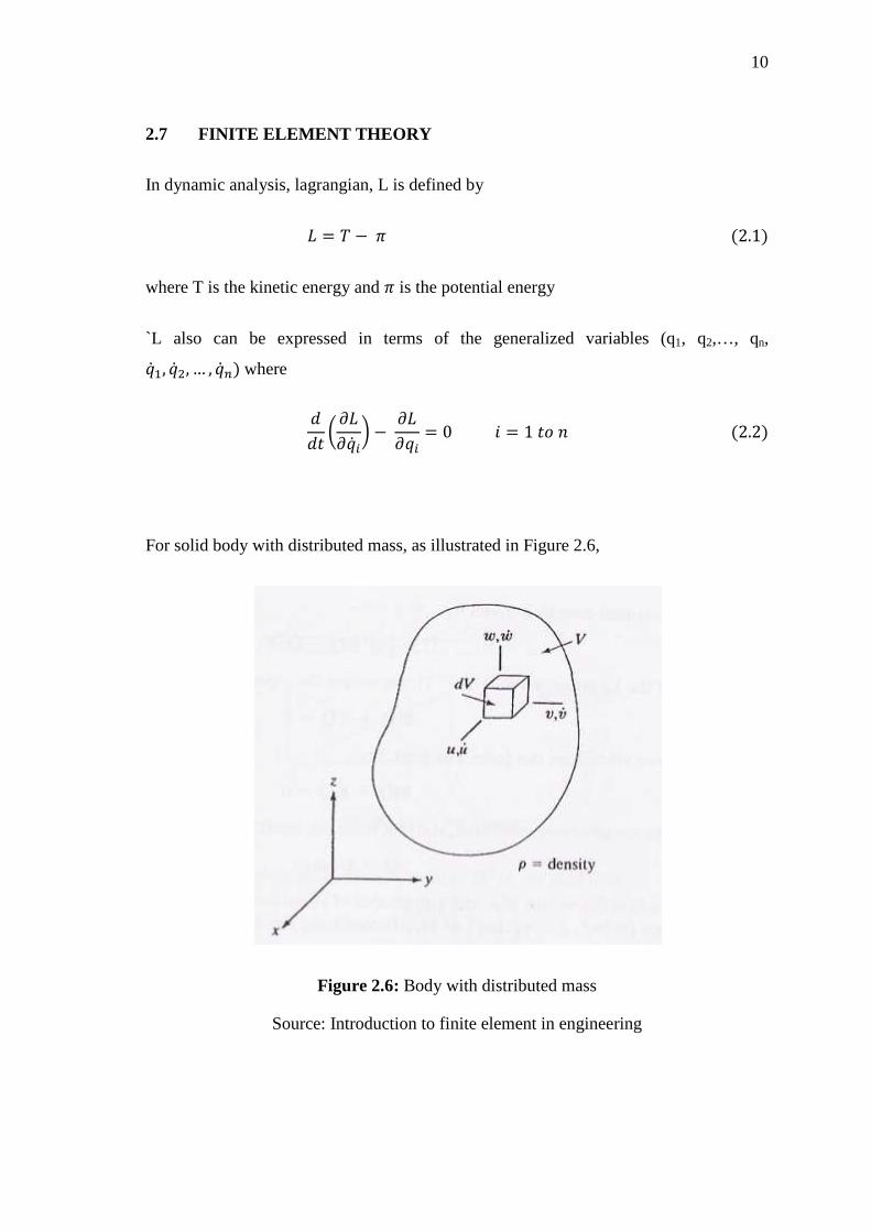
2.7 FINITE ELEMENT THEORY
In dynamic analysis, lagrangian, L is defined by
� � � � � �2.1�
where T is the kinetic energy and � is the potential energy
`L also can be expressed in terms of the generalized variables (q1, q2,…, qn, � �, � �, … , � �� where
��� � ���� �� � ����� � 0 � � 1 �� � �2.2�
For solid body with distributed mass, as illustrated in Figure 2.6,
Figure 2.6: Body with distributed mass
Source: Introduction to finite element in engineering