AUTOMATED FOOD ATTENDANCE ROBOT -...
37
AUTOMATED FOOD ATTENDANCE ROBOT NUR IZZATI BINTI ABDULLAH This thesis is submitted as partial fulfillment of the requirements for the award of the Bachelor of Electrical Engineering (Electronics) Faculty of Electrical & Electronics Engineering Universiti Malaysia Pahang NOVEMBER 2007
-
Upload
truongthien -
Category
Documents
-
view
219 -
download
0
Transcript of AUTOMATED FOOD ATTENDANCE ROBOT -...
AUTOMATED FOOD ATTENDANCE ROBOT
NUR IZZATI BINTI ABDULLAH
This thesis is submitted as partial fulfillment of the requirements for the award of the
Bachelor of Electrical Engineering (Electronics)
Faculty of Electrical & Electronics Engineering
Universiti Malaysia Pahang
NOVEMBER 2007
ii
“All the trademark and copyrights use herein are property of their respective owner.
References of information from other sources are quoted accordingly; otherwise the
information presented in this report is solely work of the author.”
Signature : ____________________________
Author : NUR IZZATI BINTI ABDULLAH
Date : NOVEMBER 2007
iii
DEDICATION
Specially dedicated to:
- My late father, who really support me doing this project until his last breath, my mom,
family, beloved ones and all friends -

iv
ACKNOWLEDGEMENT
In preparing the thesis, I was in contact with many people, researches, and
academicians. They have contributed towards my understanding and thought. In
particular, I wish to express my sincere appreciation to my main thesis supervisor, Pn.
Nor Maniha Bt Abd Ghani, for encouragement, guidance, advices and supervision. I am
also thankful to my unofficial co-supervisor, En. Mohammad Fadhil Bin Abas, for his
guidance and advice regarding PIC programming. Not forgetting, Encik Mohd Azlan
Bin Sayuti, thank you for your motivation and guidance related to the mechanical part of
the robot. Without their continued support and interest, this thesis would not have been
the same as presented here.
I am also indebted to Faculty of Electrical and Electronic, Universiti Malaysia
Pahang (UMP) for funding my final year project. Laboratory instructors, thank you for
all your cooperation especially sacrifice your resting time during weekend to open the
laboratory.
My sincere appreciation also extends to all my colleagues especially Khairul
A’alam Bin Abdul Ghani and others who have provided technical assistance and support.
Good luck in your future undertaking. Unfortunately, it is not possible to list all of them
in this limited space. I am grateful to all my family members for their non stop support.
Last but not least, thanks God for giving me a healthy body to finish this project.
Hopefully this project can contribute something useful to the committee.

v
ABSTRACT
This project presents the design and development of a robot from disposal raw
material, name automated food attendance robot. The function of the robot is to deliver a
food to unable people especially patient in hospital and old folk’s home from pantry to
their bed with just pressing a start button. This robot will follow the line tracking which
is black in colour. To sense the line, three sensors are used to detect right, center and left
line. This project consists of two parts which are software and hardware development.
The software development involved the programming for PIC 16f877 microcontroller.
Melab programmer and Microcode studio are used for this purpose. Since the raw
material that used is mostly aluminum, riveting process is used to build up the body of
the robot. After few experiment done, the project is not fully succeeded because of the
mistakes in choosing the material as will be discussed in this thesis.
vi
ABSTRAK
Projek ini membentangkan pembangunan serta reka bentuk sebuah robot dari
bahan-bahan terpakai yg diberi nama robot penghantar makanan automatik. Fungsi
utama robot ini adalah untuk menghantar makanan kepada orang-orang yang kurang
upaya terutamanya pesakit di hospital dan orang-orang tua di rumah orang-orang tua
bermula dari dapur ke katil pesakit.Robot ini akan mula berfungsi sebaik sahaja punat
mula ditekan.Pada masa ini, kerja penghantaran makanan ini dilakukan oleh atendan di
hospital manakala sukarelawan di rumah orang-orang tua. Robot ini akan menjejaki
garisan berwarna hitam sebagai panduan untuk sampai ke destinasi yang dikehendaki.
Untuk memastikan robot ini dapat menjejaki garisan berwarna tersebut, tiga pengesan
dipsangkan untuk mengesan garisan tersebut yang terdiri daripada pengesan tengah, kiri
dan kanan. Projek ini melibatkan dua bahagian iaitu pembangunan perisian serta
pembangunan reka bentuk robot tersebut. Pembangunan perisian melibatkan perisian
Microcode Studio serta pemprogram Melab untuk memprogramkan PIC 16F877.
Disebabkan kebanyakan bahan yang digunakan adalah aluminium, meribet merupakan
cara utama untuk mencantumkan bahagian-bahagian robot tersebut. Setelah menjalani
ujian beberapa kali, projek ini tidak berjaya disempurnakan dengan sepenuhnya
disebabkan pemilihan bahan yang tidak sempurna yang akan dijelaskan di dalam laporan
ini nanti.
vii
TABLE OF CONTENTS
CHAPTER TITLE PAGE
TITLE
DECLARATION
DEDICATION
ACKNOWLEDGEMENT
ABSTRACT
ABSTRAK
TABLE OF CONTENTS
LIST OF FIGURES
LIST OF TABLES
LIST OF APPENDICES
i
ii
iii
iv
v
vi
vii
xi
xii
xiii
1 INTRODUCTION
1.1 Background
1.2 Problem Statement
1.3 Objectives
1.3.1 To design a robot that can carry the
patient/disable/old folk’s meal at their
place
1.3.2 To control the robot by using PIC
microcontroller due to path tracking
1.4 Scopes of project
1
1
2
2
2
3
3
viii
2 LITERATURE REVIEW
2.1 Carrier robot “CARREY”
2.1.1 Robot Operation
2.1.2 Robot Structure
2.1.3 Review
2.2 Automated Food Attendance Robot
2.1.1 Robot Operation
2.1.2 Robot Structure
2.1.3 Review
4
4
4
5
6
7
7
8
9
3 METHODOLOGY
3.1 Overview
3.1.1 Literature review and researches
3.1.2 Robot body development
3.1.3 Circuitry design and development
3.1.4 Software development
3.1.5 Combining hardware and software
3.1.6 Documentation
10
10
11
12
12
13
13
14
4 HARDWARE DESIGN
4.1 Components
4.1.1 Motor
4.1.2 Batteries
4.1.3 PIC Microcontroller
4.1.4 Driver
4.1.5 Sensor
4.1.6 Tray
15
15
15
17
18
19
21
23
ix
4.2 Robot Body
4.2.1 Tray handle
4.2.2 Height adjustment
4.2.3 Sensor placement
4.2.4 Steering and wheel
4.2.5 Full version of robot body
24
24
25
26
27
29
5 SOFTWARE
5.1 Overview
5.2 Analog to Digital converter (ADC) program
5.3 Left sensor input
5.4 Right sensor input
5.5 Center sensor input
30
30
30
32
33
34
6 SYSTEM OPERATION
6.1 Delivering operation
6.2 Going back operation
35
35
36
7 RESULT AND DISCUSSION
7.1 Result
7.2 Discussion
38
38
39
8 CONCLUSION AND RECOMMENDATION
8.1 Conclusion
8.2 Recommendation
8.2.1 Auto Avoiding Obstacles
8.2.2 Voice Recording Function
40
40
40
41
41
x
8.2.3 Bigger robot
8.2.1 Costing and Commercialization
41
42
REFERENCE 43
APPENDICES
APPENDIX A
APPENDIX B
APPENDIX C
APPENDIX D
APPENDIX E
APPENDIX F
APPENDIX G
APPENDIX H
44
48
54
57
61
62
66
72
xi
LIST OF FIGURES
FIGURE NO TITLE PAGE
2.1
2.2
2.3
3.1
4.1
4.2
4.3
4.4
4.5
4.6
4.7
4.8
4.9
4.10
4.11
4.12
4.14
6.1
6.2
Carrier Robot “CARREY”
Automated Food Attendance robot
PU Timing Belt
Methodology Flowchart
Power Window Motor
Lead Acid Batteries
PIC 16F877 Microcontroller
MD30A Motor Driver
Structure of Detection of White and Black
Single Line detection Circuits
Commonly Used Tray
Tray Holder
(a)Height Adjuster (b) Hole to Adjust Height of Robot
Sensor placement from front view
Sensors Arrangement
(a) Differential drive (b) Synchro drive (c) Car Type Drive
Side View of Full version of robot
Delivering Operation Flowchart
Going Back operation Flowchart
4
6
8
11
16
17
18
19
21
21
22
23
24
25
25
26
27
34
35
LIST OF TABLES
TABLE NO TITLE PAGE
2.1
4.1
7.1
8.1
Control Table of the Carrier Robot
Comparison of Three Types of Wheel Driving System
Truth Table of Motor
Costing
5
26
36
40
xiii
LIST OF APPENDICES
APPENDIX TITLE PAGE
A
B
C
D
E
F
G
H
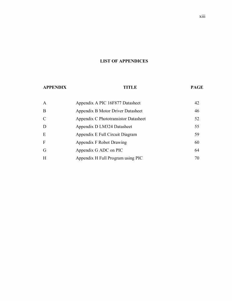
Appendix A PIC 16F877 Datasheet
Appendix B Motor Driver Datasheet
Appendix C Phototransistor Datasheet
Appendix D LM324 Datasheet
Appendix E Full Circuit Diagram
Appendix F Robot Drawing
Appendix G ADC on PIC
Appendix H Full Program using PIC
42
46
52
55
59
60
64
70
1
CHAPTER 1
INTRODUCTION
1.1 Background
There are various methods of determining the exact position of a robot within a
place. Line follower robot is one of the methods. It is the self operating robot that
follows a line that drawn on the floor. Automated food attendance robot is a line
follower based robot. But in this project it is designed so that the robot can function as a
food attendance robot. Below is the definition of each words used for this project:
(i) Automated means, use or introduction of automatic method or equipment
in place of manual labor.
(ii) Food is referred to substance taken in to maintain life growth. The meals in
this project including breakfast, lunch, tea hour, dinner and supper.
(iii) Attendance will be the persons used to deliver the meals to patients.
(iv) Robot means mechanical or virtual, artificial agent. It is usually an
Electromechanical system which, by its appearance or movements,
conveys a sense that it has intent or of its own. The word robot can
refer to both physical and virtual software agents, but the latter are usually
referred to as bots to differentiate.
Basically, the function of the robot is to carry a tray contains of patient‘s food
from kitchen to patient bed and come back to kitchen. The robot will deliver the food to
2
unable person at hospital and residents of the old folk’s home 5 times a day. It is
including breakfast, lunch, tea hour, dinner and supper. The robot will follow the path as
programmed in PIC microcontroller.
1.2 Problems Statement
Patient/old folk’s/disable people can’t move freely as healthier person and they
need someone to serve their meal. For the time being, attendance or volunteer (helpers)
in those places have doing this job. The problems occur when sometimes the helpers is
not enough to do this job while attendance is doing their others job. To overcome this
problem, I suggest to built the robot that can help both helpers and the patient/old
folk’s/disable people doing this job since robot has took place a lot of man’s work for
the past years.
1.3 Objectives
1.3.1 To design a robot that can carry the patient/disable/old folk’s meal at their
place
One of the purposes of this project is to design a robot that can carry the
patient/disable/old folk’s meal at their place. As stated before, this group of people can
be label as disable where they need some external helps in doing their daily life works
including serving their meals.
3
1.3.2 To control the robot by using PIC microcontroller due to path tracking
In order to make sure the robot is functioning, a controller to control the motor
(tire) movement automatically is needed. As PIC is one of the latest technology that used
to control the movement (by controlling the pulse width modulation (PWM) according
to input of sensor), the decision to choose PIC microcontroller as a controller of the
robot has been made. Due to a lot of pass by in both locations, path tracking is used
where there is a line that connects from the place the kitchen to the patient/old folk’s.
The line is also used to acknowledge people that it is the path for robot. So that people
can aware their step when pass thru the line.
1.4 Scopes of project
The scopes of this project are:
(i) The attendance robot is using the line follower based concept that is
redesign to be function as carrier robot.
(ii) The robot took place in hospital/old folk’s house
(iii) The robot can carry a tray at one time
(iv) The height of the robot is in range of 80cm-100cm
4
CHAPTER 2
LITERATURE REVIEW
2.1 Carrier Robot “CARREY”
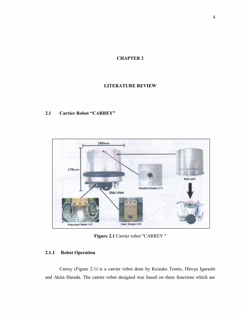
Figure 2.1 Carrier robot "CARREY "
2.1.1 Robot Operation
Carrey (Figure 2.1) is a carrier robot done by Keisuke Tomio, Hiroya Igarashi
and Akira Harada. The carrier robot designed was based on three functions which are
5
detection of user’s contact, detect black line colour and carrying the object. The robot
system has been design moves by detection of user’s contact with using primitive
mechanism. The robot was installed with vibration sensor so that it knows user is
putting something on the top if it. When the vibration sensor is activated, the robot will
move to the desire place that has been guided by the black line. In the same time, the
robot is carrying the things that have been put by the user. At the end of the line, the
second user, which is the receiver will touch the robot again to stop it and take the things
that robot has carried [1].
2.1.2 Robot Structure
Carrey robot has a dimension of 170mm height x 190mm width. It is using
microcomputer H8S/2144 to control the movement and using C language as the
development language. In order to perform the function of the robot, CARREY has been
installed by two sensors to give input to the robot. The sensors are vibration sensor and
colour detection sensor. The vibration sensor is used to detect user contact. When
vibration sensor detects the user contact, it will give input to the microcomputer to start
the robot. For colour detection sensor CARREY used three infrared LED as transmitter
and three photo IC. Each LED and photo IC is installed to sense right, centre and left. To
move the robot, two DC motor is used. Table 2.1 shows the control table of carrier
robot:
6
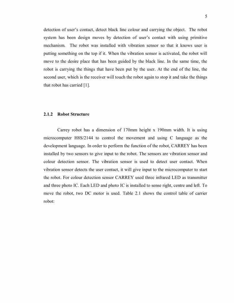
Table 2.1 Control table of the carrier robot
2.1.3 Review
According to carrier robot, the robot is looking like similar to food attendance
robot that I want to build in terms of the aim of the robot. Both robot is build to carrying
the something. In my case, the thing is patient’s food tray. In Carrey robot, the things
would be office equipment. The idea is there, but the design implementation is not
suitable for food attendance robot. Firstly, Carrey robot is too small to be implemented
as food attendance. The height is not too height so that it needs patients needs to come
down from their bed to takes the meal. Despite, because of the height is not too tall,
people will not notice the appearance of the robot that might cause incident, and the food
fall down. Second thing is, the robot is using the vibration to start move and stop. In
cases if there is something blocking their way, automatically it will stop and the food
will not be transfer to the patients.

7
2.2 Automated Food Attendance Robot
Figure 2.2 Automated food attendance robot
2.2.1 Robot Operation
Figure 2.2 shows the automated food attendance robot, done by Norsinnira
Zainul Azlan, Fadzilah Zainudin, Siti Farhanah Mohamad and Nazrah Abdul Aziz. This
robot has been design to be as one of the service robot to deliver food to people who are
unable to move. Once the button is pushed, the robot started to carry the manually
loaded tray from the kitchen to patient bed. The robot traveled by following the guiding
path. As the robot travel, the ultrasonic sensor that will detects if any obstacles that
obstruct its navigation and the alarm will sound when it meets obstacle. After reaching at
patient bed, the lifting mechanism will lift up the tray at patient bed height and the tray
is pushed to the table. Then, it will continue to travel until it arrives at another bed and
repeat the tray lifting and pushing process. For this prototype, the robot can carry two
trays for a trip [2].
8
2.2.2 Robot Structure
The structure of the robot can be divided into three parts which are mobile
platform, tray lifting mechanism and tray pushing mechanism. To ensure the mobile
platform can support the entire load, the aluminum profile and plate is chosen for the
construction of the robot. For robot motion, two DC motor with gearboxes is used to
possess high torque in order to carry heavy load. As for brain of the robot, The Motorola
MC68HC11 processor is used to control the robot to follow the line tracking. Two types
of sensors are installed to the robot. One to sense the line, which is line following
sensors (five sensors) while the other one is ultrasonic sensor that used to detect obstacle.
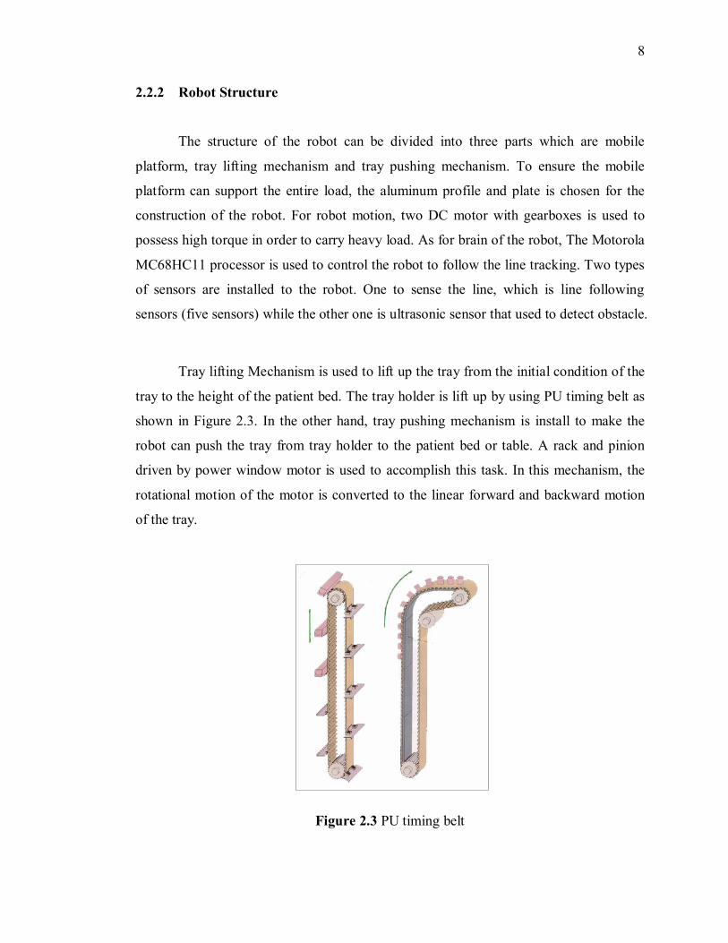
Tray lifting Mechanism is used to lift up the tray from the initial condition of the
tray to the height of the patient bed. The tray holder is lift up by using PU timing belt as
shown in Figure 2.3. In the other hand, tray pushing mechanism is install to make the
robot can push the tray from tray holder to the patient bed or table. A rack and pinion
driven by power window motor is used to accomplish this task. In this mechanism, the
rotational motion of the motor is converted to the linear forward and backward motion
of the tray.
Figure 2.3 PU timing belt

9
2.2.3 Review
According to explanation of the robot, it shows a complexity of the robot that
makes the cost of the robot becomes high. In my opinion, some of the mechanism is not
really necessary to include at the robot in order to reduce the cost. The terms that I
referred to is the tray pushing and lifting mechanism. It is good to have those parts, but it
is not the main important things to be included since it takes more than half of the total
expenses for the lifting and pushing mechanism only. The another reason that it is not
really necessary is, if we realized in hospital, the height of the bed or the table is varies.
It depends on the situation of the patient. When the height is changed, it will effect the
food in the tray is spilled, because it is not pushed at the same level. Thus, the height of
the table or bed as the reference height can not been made, unless a sensor to sense the
exact height of the table or bed at the current time is install. Third is, our mission to
deliver the food might be accomplish. The problem is, the robot might deliver the food
the bed where no patient is there because no measurement has been made to indicate
there is a people or not.
As for automated food attendance robot, it just simple and more cost effective.
Only a tray holder at the end of the robot to hold the tray and a limit switch is needed.
The limit switch is connected at the tray holder. When the tray is still there, the load
from tray will push the button and make the limit switch normally closed. Once patient
takes the tray, the limit switch will be normally open. Until then only the robot will
move to the next station.
10
CHAPTER 3
METHODOLOGY
3.1 Overview
In order to gain information for literature review to done this project, a lot of
relevant and important information can be obtained via surfing the internet, browsing
books and journals and also with the assistance from supervisor in charge and also
person that have done similar project before.
Several methods need to be implemented in order to make sure this project
success. Research is one of a good method as it can give some knowledge while doing
this project. Through these researches, a lot of information gained.
During the first semester, the project is more on gaining information towards the
project. This process is called as literature review and researches. It is continues with the
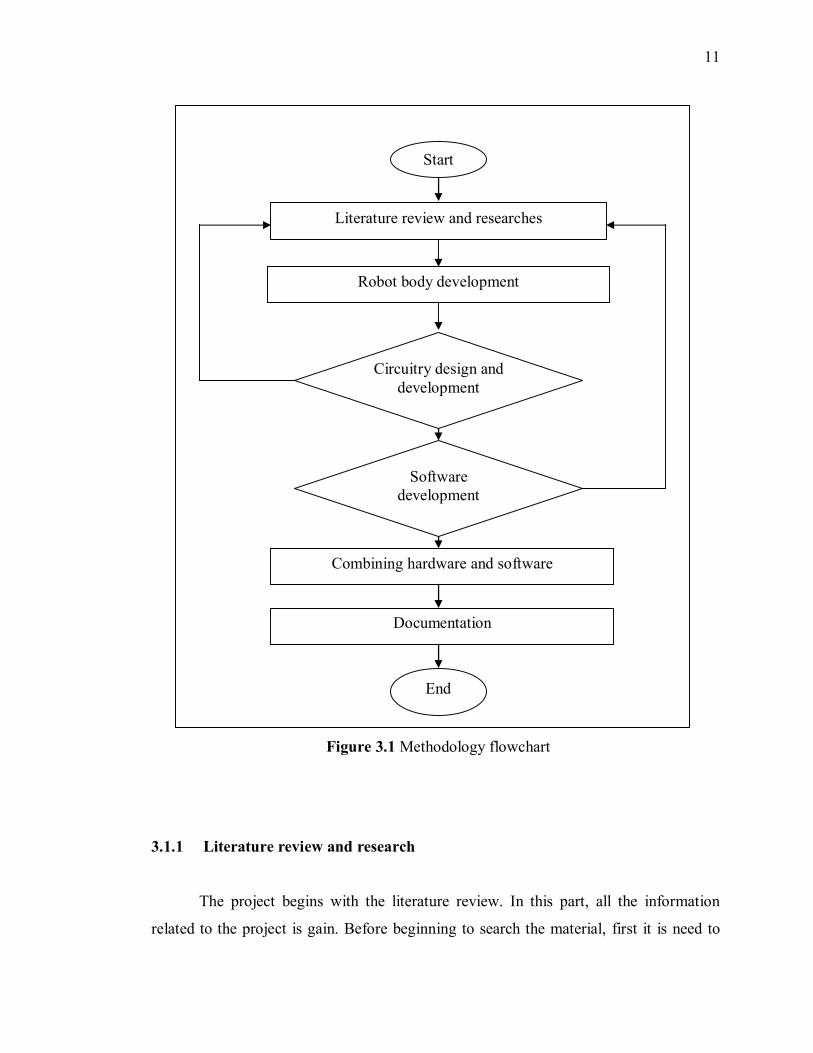
robot, circuit, and program development in second semester. The methodology flowchart
is shown as in Figure 3.1
11
3.1.1 Literature review and research
The project begins with the literature review. In this part, all the information
related to the project is gain. Before beginning to search the material, first it is need to
Figure 3.1 Methodology flowchart
Literature review and researches
Combining hardware and software
Robot body development
Documentation
Start
End
Circuitry design anddevelopment
Softwaredevelopment
12
understanding in details about the project so that the design of the robot can be drafted.
Things that should be considered in this project are the place where the robot will took
placed, who is the target for this project, the height of the patient bed and also weight of
the meals. Rather than that, information regarding to PIC microcontroller is also needed.
My referenced is based on the project that is similar to my project that has been fully
succeeded. In general, this robot is line follower type robot that is redesign to be
functioning as automated food attendance robot. As mention before, most of the
information obtained is from internet and books source. Despite, some observation has
been done to gain information related to the height of the patient bed and also weight of
the meals of patient.
3.1.2 Robot body development
After obtaining the information in literature review section, the decision to start
the project with the body development has been made. Before start the development, the
design of the robot was sketched and the material that will be used to build the robot was
estimated. The body development of this robot takes about three weeks. Most of the part
of the body comes from used and damaged trolley bag. Than, it is redesign to becomes
food attendance robot that follows the specification that I need.
3.1.3 Circuitry design and development
Next, after the development of the body design is finished, the project continues
with the circuit design and development. The circuit design includes the circuit design
for the sensor, the PIC microcontroller connection an also the motor driver connection.
Circuit design starts from a single sensor to three sensors, than followed by PIC
microcontroller connection and the motor driver connection. A step by step progress
should be done for troubleshooting purpose. While designing those circuits, a lot of
13
research has been done. Basically those circuits are provided in the internet and books.
Some adjustment must be done with the circuitry in order to make sure the objectives
and scopes of this project are followed. After the circuit is functioning, the circuit is
soldered on the strip board. When I face the problems regarding the circuit, I need to
review back to know what is the caused of the problem.
3.1.4 Software development
The robot can not be functioning without the appearance of the program. PIC
microcontroller is the brain of the system of the robot. Micro Code Studio program is
used to write the program and to check error of the program while Melab Programmer is
used to program the PIC 16F877.A step by step process should be done in order to make
easier to troubleshoot the error. The first step is to make sure that the line detecting
sensor is functioning. For this purpose, three LED is connected between the output of
the sensor and input PIC that indicates which sensor is functioning, right, center, or left.
Second step is to check the analog to digital (ADC) program is functioning. This can be
done by making simple program for ADC. For my project, I used program to ON and
OFF LED depends on which sensor is detecting the black line. The third step is to
change the ON and OFF LED program into ON and OFF motor. This has been done part
by part according to truth table. For example, when the right sensor sense the track, the
left motor will rotate while right motor stop. This shows that the robot is turning to the
right. After that, proceed to the other side of sensor. Once again, the literature review is
review back when problem occur.
3.1.5 Combining hardware and software
The next stage is to combine the hardware and software. This process is the
measurement to indicate the project is succeeded or not. Sometimes, when combining
14
the software and hardware, the robot can’t function as desired. The failure may come
from hardware problems or the hardware itself. To overcome the problem, the cause of
the problem possibility is guess and the problem is fixed by using ‘try and error’ method.
3.1.6 Documentation
All the work through out this project needs to be documented in the last step.
15
CHAPTER 4
HARDWARE DESIGN
In order to complete building the robot, there are a lot of robot parts that should
be considered in designing the robot. The parts can be divided into some components
which are:
4.1 Components
In this section, the details about the component decision will be discussed. The
components that used in projects are motor, batteries, PIC microcontroller, motor driver,
sensor and tray.
.4.1.1 Motor
In general, there are three types of motors commonly used in robotic and related
application. They are DC motor, stepper motor and servo motor.
DC motors are inexpensive, small and powerful motors that used widely. It needs
gear train reduction to reduce the speed and increase the torque output of the motor. DC
16
motor also excellent in powering the drive wheels of a mobile robot as well as powering
other mechanical assemblies.
Stepper motor in other hands is a motor that commonly used in linear
performing mechanism. Usually it is used by the robotics. One of the applications is
floppy and hard disk drive head motors.
The other type of commonly used motor is servo motor. A servo motors includes
a built-in gear train and is capable of delivering high torques directly. Unlike DC motors
and stepper motors, the servo motor has output shaft that does not rotate freely [3].
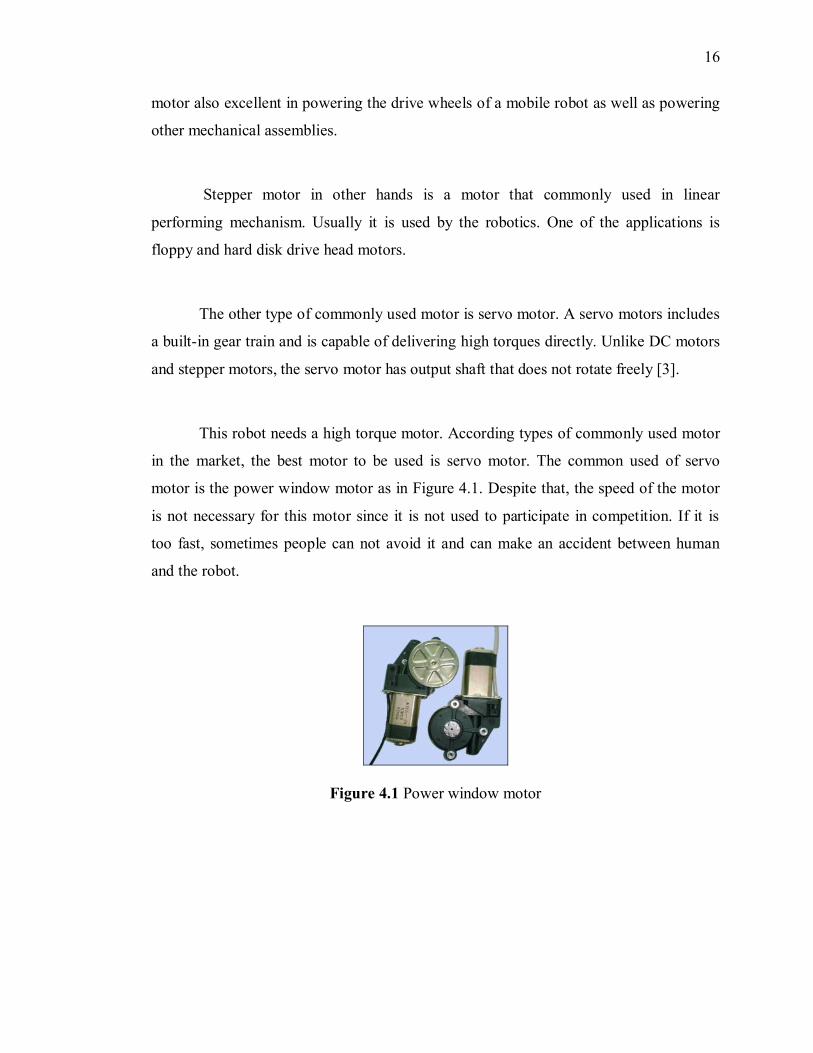
This robot needs a high torque motor. According types of commonly used motor
in the market, the best motor to be used is servo motor. The common used of servo
motor is the power window motor as in Figure 4.1. Despite that, the speed of the motor
is not necessary for this motor since it is not used to participate in competition. If it is
too fast, sometimes people can not avoid it and can make an accident between human
and the robot.
Figure 4.1 Power window motor
17
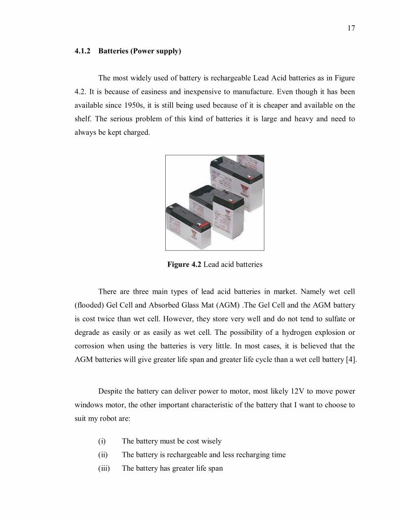
4.1.2 Batteries (Power supply)
The most widely used of battery is rechargeable Lead Acid batteries as in Figure
4.2. It is because of easiness and inexpensive to manufacture. Even though it has been
available since 1950s, it is still being used because of it is cheaper and available on the
shelf. The serious problem of this kind of batteries it is large and heavy and need to
always be kept charged.
Figure 4.2 Lead acid batteries
There are three main types of lead acid batteries in market. Namely wet cell
(flooded) Gel Cell and Absorbed Glass Mat (AGM) .The Gel Cell and the AGM battery
is cost twice than wet cell. However, they store very well and do not tend to sulfate or
degrade as easily or as easily as wet cell. The possibility of a hydrogen explosion or
corrosion when using the batteries is very little. In most cases, it is believed that the
AGM batteries will give greater life span and greater life cycle than a wet cell battery [4].
Despite the battery can deliver power to motor, most likely 12V to move power
windows motor, the other important characteristic of the battery that I want to choose to
suit my robot are:
(i) The battery must be cost wisely
(ii) The battery is rechargeable and less recharging time
(iii) The battery has greater life span
18
(iv) The battery can be used frequently in a day.
Based on characteristic above, I have chosen to select AGM battery is chosen to
be the main supply to my robot. The Lead Acid Batteries problem, which is large and
heavy, will give me an advantage. This is because the battery heaviness will give
balance to the whole robot. By putting the battery at the back will balance the robot with
the load of meals.
4.1.3 Controller (PIC microcontroller)
PIC is one of the micro controllers. PIC is used because it has its own language
(high level language), name Pic Basic Pro Compiler that is simpler for the user to
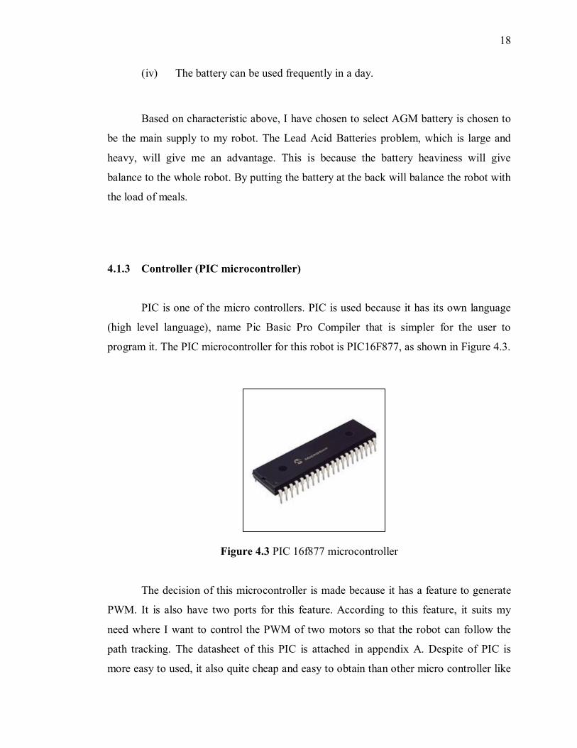
program it. The PIC microcontroller for this robot is PIC16F877, as shown in Figure 4.3.
Figure 4.3 PIC 16f877 microcontroller
The decision of this microcontroller is made because it has a feature to generate
PWM. It is also have two ports for this feature. According to this feature, it suits my
need where I want to control the PWM of two motors so that the robot can follow the
path tracking. The datasheet of this PIC is attached in appendix A. Despite of PIC is
more easy to used, it also quite cheap and easy to obtain than other micro controller like
19
Motorola 16HC 11 A that learnt in embedded micro controller subject that have a lot
like a same features to PIC 16F877. The cost of one PIC 16F877 around RM 20 in other
hand Motorola 16HC 11A is about RM 40. The data sheet of the PIC 16F877 as in
appendix A
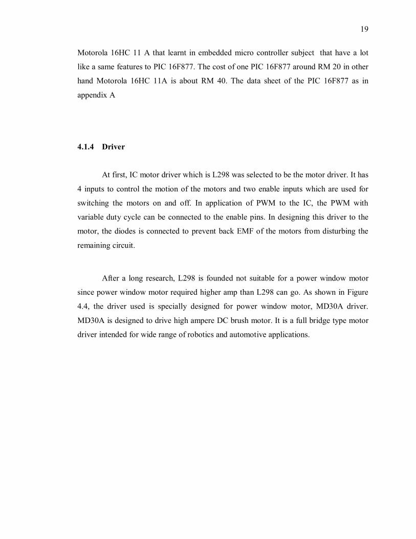
4.1.4 Driver
At first, IC motor driver which is L298 was selected to be the motor driver. It has
4 inputs to control the motion of the motors and two enable inputs which are used for
switching the motors on and off. In application of PWM to the IC, the PWM with
variable duty cycle can be connected to the enable pins. In designing this driver to the
motor, the diodes is connected to prevent back EMF of the motors from disturbing the
remaining circuit.
After a long research, L298 is founded not suitable for a power window motor
since power window motor required higher amp than L298 can go. As shown in Figure
4.4, the driver used is specially designed for power window motor, MD30A driver.
MD30A is designed to drive high ampere DC brush motor. It is a full bridge type motor
driver intended for wide range of robotics and automotive applications.
20
Figure 4.4 MD30A motor driver
With minimum interface, the board is ready to be plugged and play. The board
also includes two push buttons for fast test run. The driver is ready to drive high current
motor by just connecting the driver with supply. The specification of the motor driver is
as below:
(i) Able to provide high current up to 30Amp.
(ii) Able to control heavy duty motor such as Power Window Motor, Power
Wiper Motor or even Starter Motor.
(iii) Capable to control a motor in bi-directional.
(iv) Speed control can be accomplished by Pulse Width Modulator (PWM).
(v) Input voltage for motor is determined by users (12VDC, 24VDC, etc).
(vi) Easy to control by connect 5 lead wires (Gnd, PWM, CCW, CW, Vcc) to
PIC controller.
The details according to MD30A can be referred as in appendix B.
21
4.1.5 Sensor
The most important part for my robot is the sensor. Without appearance of a
robot, robot will not have any input. It will be just like a machine. Robot needs sensor to
let them know what is happening in their world and be able to react with the changing
situations [3].
In this part, the sensor used in for detecting line was considered. The cheapest
choice of diode is to use standard red LED's as for light source. The LED used is white
LED since it can give more light to the detector comparing to the other colour of LED.
As for the receiver, phototransistor is used. Phototransistor that used is L14G1. Instead
of using standard red LED's some said that, the use infra red light is better. Infra red
gives some advantages is based on there isn't so much infra red light in sunlight as there
is red light and that's why it's possible to make detectors with build in daylight filter. As
its pair, the infrared detector is used. But, since the robot is used in door, the
consideration of the sunlight can be ignored. So, it is not important to used infrared light
to replace the LED.
How the sensor does works? At first, emit the white LED towards the floor. It
will reflect almost all light if the floor is white in colour. As the result, the
phototransistor will detect a strong signal comes from the reflection of the LED light
mean while if the floor is black, it absorbs almost all the LED. In other words, the robot
can distinguish between white and black line by detecting the strength of the reflected
light signal which will given different value of voltage. Below is the structure of
detection of white and black.
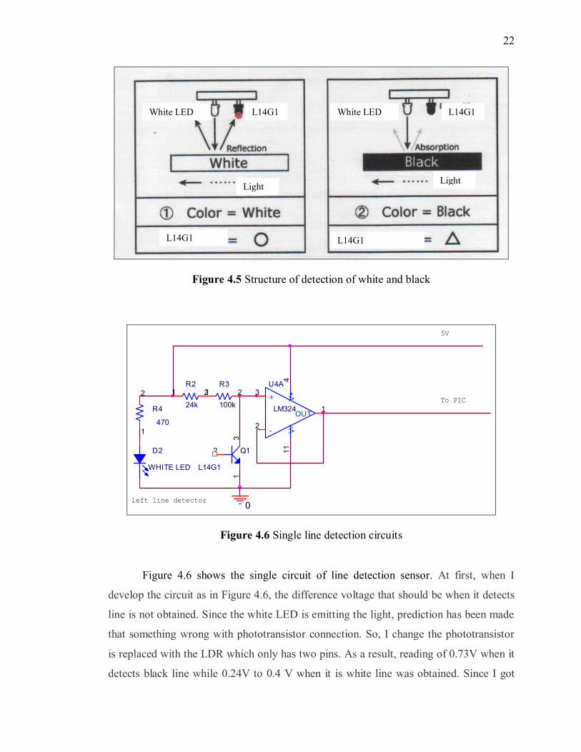
22
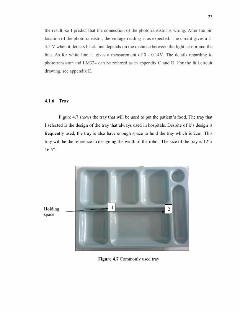
Figure 4.5 Structure of detection of white and black
R4
470
2
1
Q1
L14G1
3
2
1
D2
WHITE LED
To PIC
0
R2
24k
21
5V
U4A
LM324
3
2
411
1+
-
V+
V-
OUT
R3
100k
21
left line detector
Figure 4.6 Single line detection circuits
Figure 4.6 shows the single circuit of line detection sensor. At first, when I
develop the circuit as in Figure 4.6, the difference voltage that should be when it detects
line is not obtained. Since the white LED is emitting the light, prediction has been made
that something wrong with phototransistor connection. So, I change the phototransistor
is replaced with the LDR which only has two pins. As a result, reading of 0.73V when it
detects black line while 0.24V to 0.4 V when it is white line was obtained. Since I got
White LED L14G1
L14G1 L14G1
White LED L14G1
Light Light
23
the result, so I predict that the connection of the phototransistor is wrong. After the pin
location of the phototransistor, the voltage reading is as expected. The circuit gives a 2-
3.5 V when it detects black line depends on the distance between the light sensor and the
line. As for white line, it gives a measurement of 0 - 0.14V. The details regarding to
phototransistor and LM324 can be referred as in appendix C and D. For the full circuit
drawing, see appendix E.
4.1.6 Tray
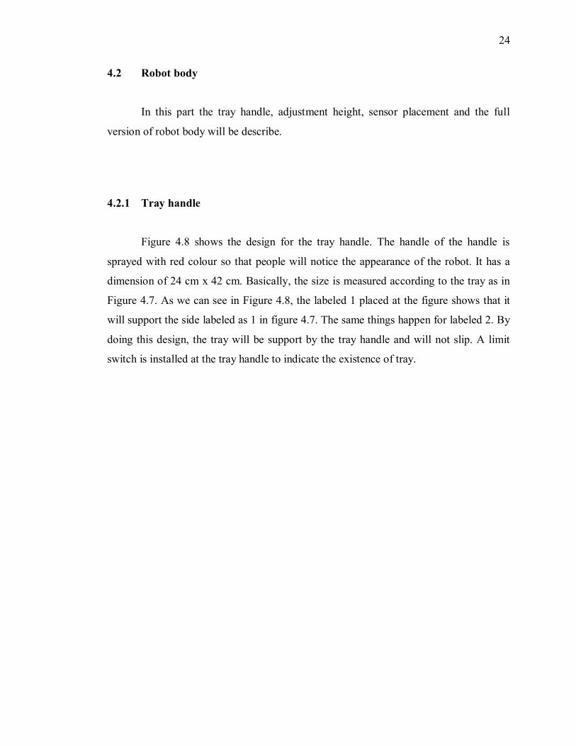
Figure 4.7 shows the tray that will be used to put the patient’s food. The tray that
I selected is the design of the tray that always used in hospitals. Despite of it’s design is
frequently used, the tray is also have enough space to hold the tray which is 2cm. This
tray will be the reference in designing the width of the robot. The size of the tray is 12”x
16.5”.
Figure 4.7 Commonly used tray
Holdingspace
1 2
24
4.2 Robot body
In this part the tray handle, adjustment height, sensor placement and the full
version of robot body will be describe.
4.2.1 Tray handle
Figure 4.8 shows the design for the tray handle. The handle of the handle is
sprayed with red colour so that people will notice the appearance of the robot. It has a
dimension of 24 cm x 42 cm. Basically, the size is measured according to the tray as in
Figure 4.7. As we can see in Figure 4.8, the labeled 1 placed at the figure shows that it
will support the side labeled as 1 in figure 4.7. The same things happen for labeled 2. By
doing this design, the tray will be support by the tray handle and will not slip. A limit
switch is installed at the tray handle to indicate the existence of tray.