NFPA 72 and en 54 Products Assessment of Compatibility Rev2
33
US NATIONAL FIRE ALARM CODE NFPA 72 AND EUROPEAN STANDARDS IN THE EN54 SERIES - ASSESSMENT OF COMPATIBILITY 27 May 2010 Document Number PN220
Transcript of NFPA 72 and en 54 Products Assessment of Compatibility Rev2

US NATIONAL FIRE ALARM CODE NFPA 72 AND EUROPEAN STANDARDS IN THE EN54 SERIES - ASSESSMENT OF COMPATIBILITY 27 May 2010
Document Number PN220
1
BRE Global Document Number PN220 – Rev 2 Commercial in confidence
© BRE Global Ltd 2010
Edited on behalf of BRE Global by
Name Dr Robert Dudley
Position Director - Electronics Research
Approved on behalf of BRE Global by
Name Mick Gower
Position Director of Fire and Security
Date 27 May 2010
BRE Global Bucknalls Lane Watford Herts WD25 9XX T + 44 (0) 1923 664100 F + 44 (0) 1923 664994 E [email protected] www.breglobal.com
This report is made on behalf of BRE Global. By receiving the report and acting on it, the client - or any third party relying on it - accepts that no individual is personally liable in contract, tort or breach of statutory duty (including negligence).
2
BRE Global Document Number PN220 – Rev 2 Commercial in confidence
© BRE Global Ltd 2010
Executive Summary
Within the worldwide community of manufacturers of automatic fire detection and alarm equipment and system designers and installers, there is a commonly held view that equipment designed to meet the European EN54 Fire detection and fire alarm systems standard cannot be used within an installation designed to the US National Fire Alarm Code, NFPA 72.
This long held assumption has been tested by BRE Global by commissioning C. S. Todd & Associates to conduct an assessment of the issues relating to equipment compatibility between the EN54 standards and the NFPA 72 code. The results of this study for each of the product categories assessed have shown that there are very few performance and functionality issues that need to be addressed.
Authorities having jurisdiction (AHJ) should be able to use the findings presented in this report to make informed decisions in respect of using EN54 compliant equipment in NFPA 72 systems. However, it is a critical requirement that AHJs only permit the use of equipment that meets the applicable EN54 standard that is listed by a recognised third party certification body.
3
BRE Global Document Number PN220 – Rev 2 Commercial in confidence
© BRE Global Ltd 2010
Contents
1. Introduction 4
2. Assessment Procedures 6
3. EN54-2: 1998 Control and Indicating Equipment 7
4. EN54-3: 2001 Sounders 13
5. EN54-4: 1998 Power Supply Equipment 16
6. EN54-5: 2001 Heat Detectors – Point Detectors 19
7. EN54-7: 2001 Smoke Detectors – Point Detectors Using Scattered Light or Ionization 22
8. EN54-10: 2002 Flame Detectors 25
9. EN54-11: 2001 Manual Call Points 27
10. EN54-12: 2002 Smoke Detectors – Line Detectors Using an Optical Beam 28
11. EN54-17: 2005 Short Circuit Isolators 29
12. EN54-18: 2005 Input/Output Devices 30
13. Approvals, Listings and General Comments 31
14. Conclusions 32

4
BRE Global Document Number PN220 – Rev 2 Commercial in confidence
© BRE Global Ltd 2010
1. Introduction
1.1 There is an increasing tendency in some countries for consultants to specify the need for compliance of automatic fire detection and alarm systems with the US National Fire Alarm Code NFPA 72, leading to an assumption that ANSI/UL or FM product specifications are required. BRE Global considers that products complying with EN54 standards are suitable for use in such systems specified to comply with NFPA 72. To obtain an independent confirmation of this, C.S. Todd & Associates were instructed to provide an assessment of compatibility. C. S. Todd & Associates is a fire safety and fire engineering consultancy based in Farnham, UK (www.cstodd.co.uk).
1.2 This report contains the findings of an assessment of the compatibility of European Standards
EN54-2, EN54-3, EN54-4, EN54-5, EN54-7, EN54-10, EN54-11, EN54-12, EN54-17 and EN54-18 with the requirements of the 2007 version of the US National Fire Alarm Code NFPA 72. A revised version of the code was published at the beginning of 2010 but it is not considered that the revisions made in the latest version of NFPA 72 code affect the basis of this assessment.
1.3 For the study, reference has been made extensively to the 2007 version of NFPA 72 code and to the following European Standards, as amended to date:
• EN54-2: 1998. Fire detection and fire alarm systems - Control and indicating equipment. • EN54-3: 2001. Fire detection and fire alarm systems - Fire alarm devices. Sounders. • EN54-4: 1998. Fire detection and fire alarm systems - Power supply equipment. • EN54-5: 2001. Fire detection and fire alarm systems - Heat detectors. Point detectors. • EN54-7: 2001. Fire detection and fire alarm systems - Smoke detectors – Point detectors using
scattered light, transmitted or ionization. • EN54-10: 2002. Fire detection and fire alarm systems - Flame detectors. Point detectors. • EN54-11: 2001. Fire detection and fire alarm systems – Manual call points. • EN54-12: 2002. Fire detection and fire alarm systems - Smoke detectors. Line detectors using
an optical light beam. • EN54-17: 2005. Fire detection and Fire Alarm Systems – Short-circuit isolators. • EN54-18: 2005. Fire detection and Fire Alarm Systems – Input/output devices
1.4 Section 2 refers to the assessment procedures used. Sections 3 to 12, respectively, contain the
findings from the study in respect of the European Standards listed in 1.3. Section 13 contains information on approvals and listings as well as general comments, and in Section 14 the conclusions of the study are summarised.
1.5 The submission of this report constitutes neither a warranty by BRE Global, nor an assurance
against risk. The findings of the study represent only the best judgement of BRE Global and the consultants involved in interpreting the relevant standards and code. No liability whatsoever is accepted for the accuracy of such information.
1.6 Permission to reproduce extracts from British Standards is granted by the British Standards
Institution (BSI). No other use of this material is permitted. British Standards can be obtained in PDF or hard copy formats from the BSI online shop: http://shop.bsigroup.com or by contacting BSI Customer Services for hard copies only: Tel: +44 (0)20 8996 9001, Email: [email protected].
5
BRE Global Document Number PN220 – Rev 2 Commercial in confidence
© BRE Global Ltd 2010
1.7 In granting permission for use of material from NFPA 72-2007, the National Fire Protection Association (NFPA) has considered only the quantity of material reproduced from that standard, has undertaken no technical review or verification of this document and has undertaken no review whatsoever of EN54. NFPA makes no statement of approval or concurrence with any comparisons included or conclusions drawn herein, and disclaims any responsibility for any such comparisons or conclusions. NFPA notes that equipment installed in conformity with NFPA 72 must be listed for the purpose and that equipment listing generally involves evaluations of products or services in accordance with designated standards by organisations acceptable to the authority having jurisdiction. Designated standards are generally those identified in NFPA 72 Chapter 2, Reference Publications, and Annex G, Informational References. NFPA assumes no responsibility for claims of equivalence based on equipment evaluations using other standards. NFPA further notes that NFPA Codes and Standards are intended to be used as a whole and not as isolated excerpts.
1.8 All material from NFPA 72-2007 is © 2007 National Fire Protection Association, all rights
reserved.
6
BRE Global Document Number PN220 – Rev 2 Commercial in confidence
© BRE Global Ltd 2010
2. Assessment Procedures
2.1 For each relevant part of EN54, a search was made in the NFPA 72 Code for references to the particular equipment or device, and a list was made of the appropriate extracts.
2.2 Where these extracts relate to the manner in which the device or equipment forms part of a fire
alarm system, such extracts were excluded from further consideration. For example, in the case of manual call points, while the definition extracted from NFPA 72, “a manually operated device used to initiate an alarm signal” was compared with the requirement in EN54-11, the statement, “The operable part of each manual fire alarm box shall be not less than 1.1 m (3½ ft) and not more than 1.37 m (4½ ft) above floor level” is a “code of practice” recommendation and was not therefore given further consideration.
2.3 NFPA 72 includes reference to equipment that includes versions of the relevant devices and
equipment covered by this assessment. For example, in the USA, McCulloh systems using coded fire alarm boxes are covered by NFPA 72. It is assumed that EN54 devices/equipment could be used in such applications. In McCulloh systems, for example, manual call points to EN54-11 could be supplied with the necessary associated components, housing, etc. However, it is likely that most applications of this type will relate to practices common within the USA, but presumably not outside the USA, and that there will not therefore be a real requirement for EN54 devices/equipment to form part of such “extended” equipment.
2.4 Only extracts from NFPA 72 relating to the design or construction of the EN54 devices and
equipment have been included in the following sections of this assessment.

7
BRE Global Document Number PN220 – Rev 2 Commercial in confidence
© BRE Global Ltd 2010
3. EN54-2: 1998 Control and Indicating Equipment
3.1 Key Requirements of NFPA 72
NFPA 72 sub-clause
Text Comment
4.4.3.3 Distinctive Signals. Fire alarms, supervisory signals, and trouble signals shall be distinctively and descriptively annunciated.
EN54-2 requires in 5.1.1 that, “The CIE shall be capable of unambiguously indicating the following functional conditions, as described in clauses 6 to 10. ± Quiescent condition. ± Fire alarm condition. ± Fault warning condition. ± Disablement condition. Test condition (if provided).”
4.4.3.5 Trouble Signals. 4.4.3.5.1 Trouble signals and their restoration to normal shall be indicated within 200 seconds at the locations identified in 4.4.3.5.6 or 4.4.3.5.7. Indication of primary power failure trouble signals transmitted to a supervising station shall be delayed in accordance with 4.4.7.3.3.
EN54-2 requires in 8.1.3 that, “The CIE shall enter the fault warning condition within 100 s of the occurrence of the fault or the reception of a fault signal, or within another time as specified in this European Standard or in other parts of EN54.” (Power supply fault indications are dealt with in the assessment of EN54-4.)
4.4.3.5.2 Trouble signals required to indicate at the protected premises shall be indicated by distinctive audible signals, which shall be distinctive from alarm signals.
EN54-2 requires in 5.5 that, “The audible indication for the fire alarm condition may be the same as that for the fault warning condition. If they are different, the fire alarm indication shall have priority.” This could result in a non-compliance with the requirements of NFPA 72 but most control panels do have different signals for fire and fault indication, e.g. continuous for fire, pulsing for fault.
4.4.3.5.3 If an intermittent signal is used, it shall sound at least once every 10 seconds, with a minimum duration of 1⁄2 second.
This is not specified in EN54-2 but, in practice, where an intermittent signal is used, the “on” period is normally longer than ½ second.
4.4.3.5.4 An audible trouble signal shall be permitted to be common to several supervised circuits.
This is a rather general statement. EN54-2, in this respect, is more stringent.

8
BRE Global Document Number PN220 – Rev 2 Commercial in confidence
© BRE Global Ltd 2010
NFPA 72 sub-clause
Text Comment
4.4.3.5.6 Visible and audible trouble signals and visible indication of their restoration to normal shall be indicated at the following locations:
(1) Fire alarm control unit for protected premises alarm systems
EN54-2 does not make this statement, but the requirement is implicit in its various requirements for indications. For example, 8.1.1 states, “The CIE shall enter the fault warning condition when signals are received which, after any necessary processing, are interpreted as a fault.”
4.4.3.5.8.1 A means for silencing the trouble notification appliance(s) shall be permitted only if it complies with 4.4.3.5.8.1(A) through 4.4.3.5.8.1(D). (A) The means shall be key-operated, located within a locked enclosure, or arranged to provide equivalent protection against unauthorized use. (B) The means shall transfer the trouble indication to a suitably identified lamp or other acceptable visible indicator. © The visible indication in 4.4.3.5.8.1(B) shall persist until the trouble condition has been corrected. (D) The audible trouble signal shall sound when the silencing means is in its silence position and no trouble exists.
Relevant parts of EN54-2 are as follows. “8.6.1 The audible indication of faults under 8.2 and, if provided, 8.3, shall be capable of being silenced manually at access level 1 or 2. The same manual operation may be used as that for silencing the audible indication in the fire alarm condition. 8.6.2 The audible indication shall be silenced automatically if the CIE is automatically reset from the fault warning condition. 8.6.3 If previously silenced, the audible indication shall re-sound for each newly recognised fault.” In this case, NFPA 72 requirements are stricter than those in EN54-2. If this were an issue, a control panel with the means for silencing the audible fault indication at level 2 rather than level 1 could be used. 4.4.3.5.8.1(D) would not normally apply because the silence control would be a momentary-action switch.
9
BRE Global Document Number PN220 – Rev 2 Commercial in confidence
© BRE Global Ltd 2010
NFPA 72 sub-clause
Text Comment
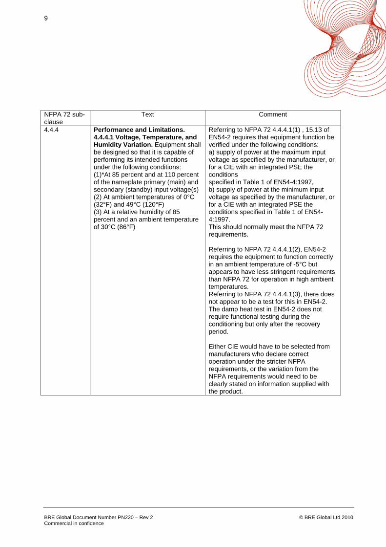
4.4.4 Performance and Limitations. 4.4.4.1 Voltage, Temperature, and Humidity Variation. Equipment shall be designed so that it is capable of performing its intended functions under the following conditions: (1)*At 85 percent and at 110 percent of the nameplate primary (main) and secondary (standby) input voltage(s) (2) At ambient temperatures of 0°C (32°F) and 49°C (120°F) (3) At a relative humidity of 85 percent and an ambient temperature of 30°C (86°F)
Referring to NFPA 72 4.4.4.1(1) , 15.13 of EN54-2 requires that equipment function be verified under the following conditions: a) supply of power at the maximum input voltage as specified by the manufacturer, or for a CIE with an integrated PSE the conditions specified in Table 1 of EN54-4:1997, b) supply of power at the minimum input voltage as specified by the manufacturer, or for a CIE with an integrated PSE the conditions specified in Table 1 of EN54-4:1997. This should normally meet the NFPA 72 requirements. Referring to NFPA 72 4.4.4.1(2), EN54-2 requires the equipment to function correctly in an ambient temperature of -5°C but appears to have less stringent requirements than NFPA 72 for operation in high ambient temperatures. Referring to NFPA 72 4.4.4.1(3), there does not appear to be a test for this in EN54-2. The damp heat test in EN54-2 does not require functional testing during the conditioning but only after the recovery period. Either CIE would have to be selected from manufacturers who declare correct operation under the stricter NFPA requirements, or the variation from the NFPA requirements would need to be clearly stated on information supplied with the product.

10
BRE Global Document Number PN220 – Rev 2 Commercial in confidence
© BRE Global Ltd 2010
NFPA 72 sub-clause
Text Comment
4.4.7.1* Monitoring Integrity of Installation Conductors and Other Signaling Channels. Unless otherwise permitted or required by 4.4.7.1.1 through 4.4.7.1.13, all means of interconnecting equipment, devices, and appliances and wiring connections shall be monitored for the integrity of the interconnecting conductors or equivalent path so that the occurrence of a single open or a single ground-fault condition in the installation conductors or other signaling channels and their restoration to normal shall be automatically indicated within 200 seconds.
EN54-2 requires monitoring of such connections for open-circuit faults. 8.2.4c) of EN54-2 requires, “an indication, at least common to any single earth fault which affects a mandatory function, and which is not otherwise indicated as a fault of a supervised function;” This statement is certainly in the spirit of the NFPA 72 requirement.
4.4.7.1.15 Unacknowledged alarm signals shall not be interrupted if a fault on an initiating device circuit or a signaling line circuit occurs while there is an alarm condition on that circuit. Exception: Circuits used to interconnect fire alarm control units.
This requirement is not very clear. If it refers to a requirement for latching of input signals, then this is covered in EN54-2.
4.4.7.1.16 An open, ground, or short-circuit fault on the installation conductors of one alarm notification appliance circuit shall not affect the operation of any other alarm notification circuit.
This requirement could not be found in EN54-2 but, in practice, control panels comply with it, because dedicated sounder circuits are protected by fuses.
4.4.7.1.17 A wire-to-wire short-circuit fault on any alarm notification appliance circuit shall result in a trouble signal in accordance with 4.4.3.5, except as permitted by 4.4.7.1.4, 4.4.7.1.5, or 4.4.7.1.10.
This is covered by 8.2.5 of EN54-2.
6.4.2.1.2 An open or ground condition shall result in the annunciation of a trouble signal at the protected premise within 200 seconds as required in 4.4.7.
This refers to the “Class” of circuit, as defined in NFPA 72. It is covered by 8.2.4 and/or 8.2.5 of EN54-2.
6.6.2 Where digital communications are used, inability to send or receive digital signals over a signaling line circuit shall be indicated by a trouble signal.
The “inability to send or receive digital signals” would be caused either by a line fault (which would be covered by 8.2.4 or 8.2.5 of EN54-2) or, normally, by a failure of a processor involved in the communication process. The latter would be indicated under the requirements of 13.4 of EN54-2.

11
BRE Global Document Number PN220 – Rev 2 Commercial in confidence
© BRE Global Ltd 2010
NFPA 72 sub-clause
Text Comment
6.8.1.3.1.1 The signal from an automatic fire detection device selected for positive alarm sequence operation shall be acknowledged at the fire alarm control unit by trained personnel within 15 seconds of annunciation in order to initiate the alarm investigation phase. If the signal is not acknowledged within 15 seconds, notification signals in accordance with the building evacuation or relocation plan and remote signals shall be automatically and immediately activated.
This is a staff alarm requirement. Available control panels are normally able to handle such requirements. Relevant options with requirements are given in 7.12 of EN54-2.
6.8.2.1
Fire alarm systems shall be permitted to be either integrated systems combining all detection, notification, and auxiliary functions in a single system or a combination of component subsystems. Fire alarm system components shall be permitted to share control equipment or shall be able to operate as stand-alone subsystems, but, in any case, they shall be arranged to function as a single system.
Nothing was found in EN54-2 to conflict with these requirements.
6.8.5.4.2 If automatic drift compensation of sensitivity for a fire detector is provided, the fire alarm control unit shall identify the affected detector when the limit of compensation is reached.
EN54-2 does not generally include requirements relating to fault indication of initiating device condition. However, where automatic drift compensation is provided in detectors, control and indicating equipment suitable for use with these detectors provides the (addressable) identification indication required by NFPA 72.
6.16.2.4 The installation wiring between the fire alarm control unit and the relay or other appliance shall be monitored for integrity.
Currently available control and indicating equipment normally has auxiliary outputs which are monitored for line faults. (EN54-2 does not specify that they need to have these to comply with that standard.)
12
BRE Global Document Number PN220 – Rev 2 Commercial in confidence
© BRE Global Ltd 2010
NFPA 72 sub-clause
Text Comment
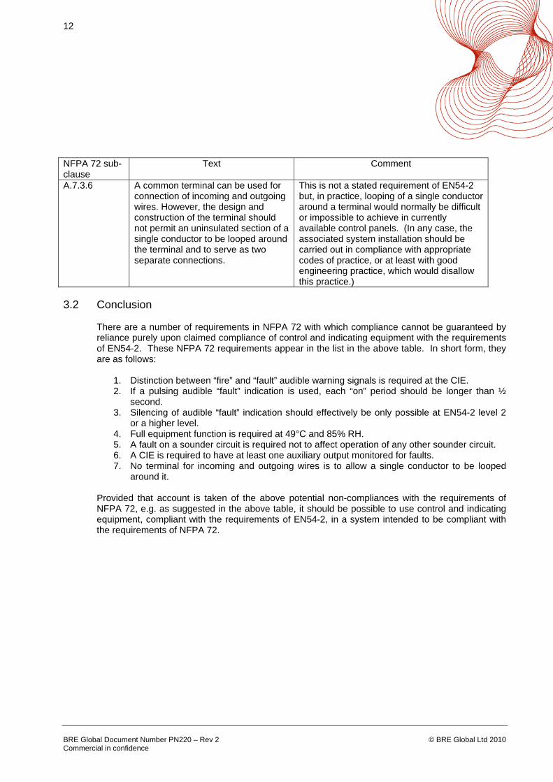
A.7.3.6 A common terminal can be used for connection of incoming and outgoing wires. However, the design and construction of the terminal should not permit an uninsulated section of a single conductor to be looped around the terminal and to serve as two separate connections.
This is not a stated requirement of EN54-2 but, in practice, looping of a single conductor around a terminal would normally be difficult or impossible to achieve in currently available control panels. (In any case, the associated system installation should be carried out in compliance with appropriate codes of practice, or at least with good engineering practice, which would disallow this practice.)
3.2 Conclusion
There are a number of requirements in NFPA 72 with which compliance cannot be guaranteed by reliance purely upon claimed compliance of control and indicating equipment with the requirements of EN54-2. These NFPA 72 requirements appear in the list in the above table. In short form, they are as follows:
1. Distinction between “fire” and “fault” audible warning signals is required at the CIE. 2. If a pulsing audible “fault” indication is used, each “on” period should be longer than ½
second. 3. Silencing of audible “fault” indication should effectively be only possible at EN54-2 level 2
or a higher level. 4. Full equipment function is required at 49°C and 85% RH. 5. A fault on a sounder circuit is required not to affect operation of any other sounder circuit. 6. A CIE is required to have at least one auxiliary output monitored for faults. 7. No terminal for incoming and outgoing wires is to allow a single conductor to be looped
around it.
Provided that account is taken of the above potential non-compliances with the requirements of NFPA 72, e.g. as suggested in the above table, it should be possible to use control and indicating equipment, compliant with the requirements of EN54-2, in a system intended to be compliant with the requirements of NFPA 72.
13
BRE Global Document Number PN220 – Rev 2 Commercial in confidence
© BRE Global Ltd 2010
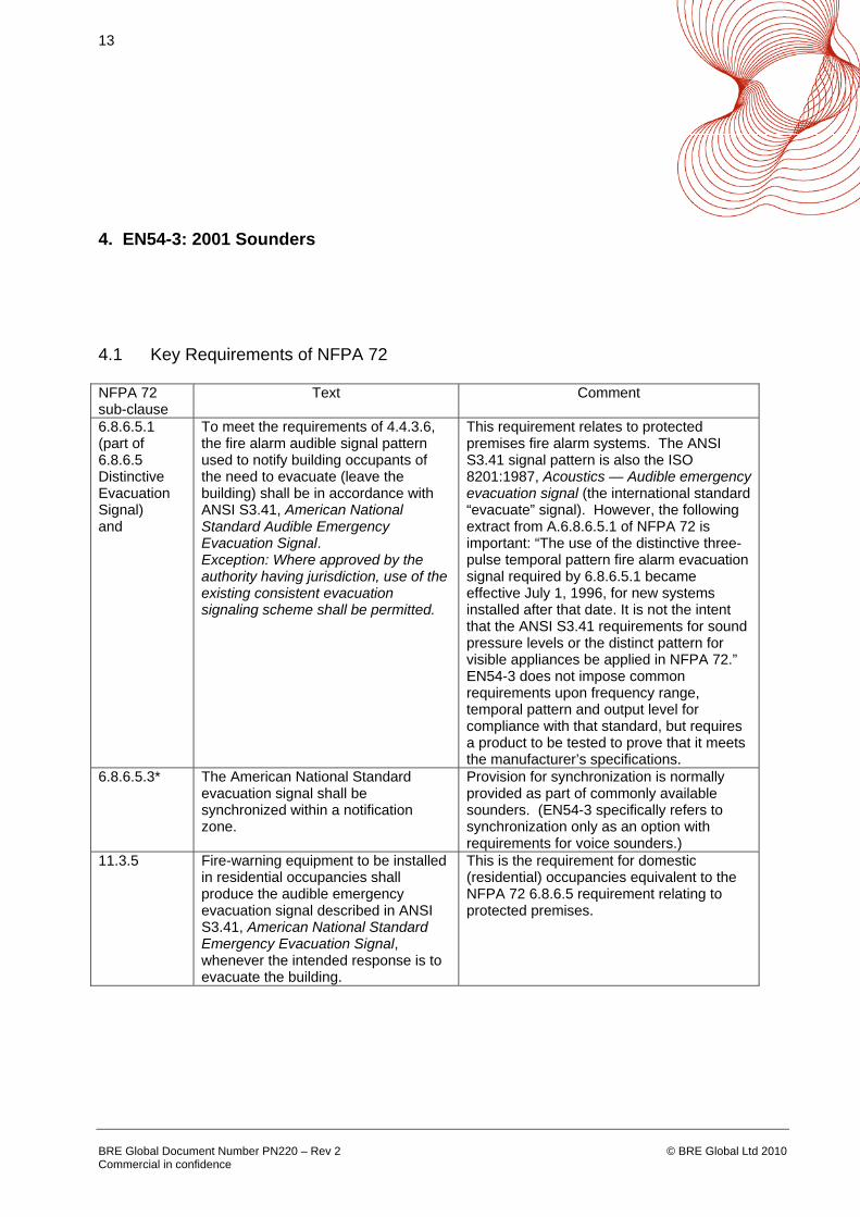
4. EN54-3: 2001 Sounders
4.1 Key Requirements of NFPA 72 NFPA 72 sub-clause
Text Comment
6.8.6.5.1 (part of 6.8.6.5 Distinctive Evacuation Signal) and
To meet the requirements of 4.4.3.6, the fire alarm audible signal pattern used to notify building occupants of the need to evacuate (leave the building) shall be in accordance with ANSI S3.41, American National Standard Audible Emergency Evacuation Signal. Exception: Where approved by the authority having jurisdiction, use of the existing consistent evacuation signaling scheme shall be permitted.
This requirement relates to protected premises fire alarm systems. The ANSI S3.41 signal pattern is also the ISO 8201:1987, Acoustics — Audible emergency evacuation signal (the international standard “evacuate” signal). However, the following extract from A.6.8.6.5.1 of NFPA 72 is important: “The use of the distinctive three-pulse temporal pattern fire alarm evacuation signal required by 6.8.6.5.1 became effective July 1, 1996, for new systems installed after that date. It is not the intent that the ANSI S3.41 requirements for sound pressure levels or the distinct pattern for visible appliances be applied in NFPA 72.” EN54-3 does not impose common requirements upon frequency range, temporal pattern and output level for compliance with that standard, but requires a product to be tested to prove that it meets the manufacturer’s specifications.
6.8.6.5.3* The American National Standard evacuation signal shall be synchronized within a notification zone.
Provision for synchronization is normally provided as part of commonly available sounders. (EN54-3 specifically refers to synchronization only as an option with requirements for voice sounders.)
11.3.5 Fire-warning equipment to be installed in residential occupancies shall produce the audible emergency evacuation signal described in ANSI S3.41, American National Standard Emergency Evacuation Signal, whenever the intended response is to evacuate the building.
This is the requirement for domestic (residential) occupancies equivalent to the NFPA 72 6.8.6.5 requirement relating to protected premises.
14
BRE Global Document Number PN220 – Rev 2 Commercial in confidence
© BRE Global Ltd 2010
NFPA 72 sub-clause
Text Comment
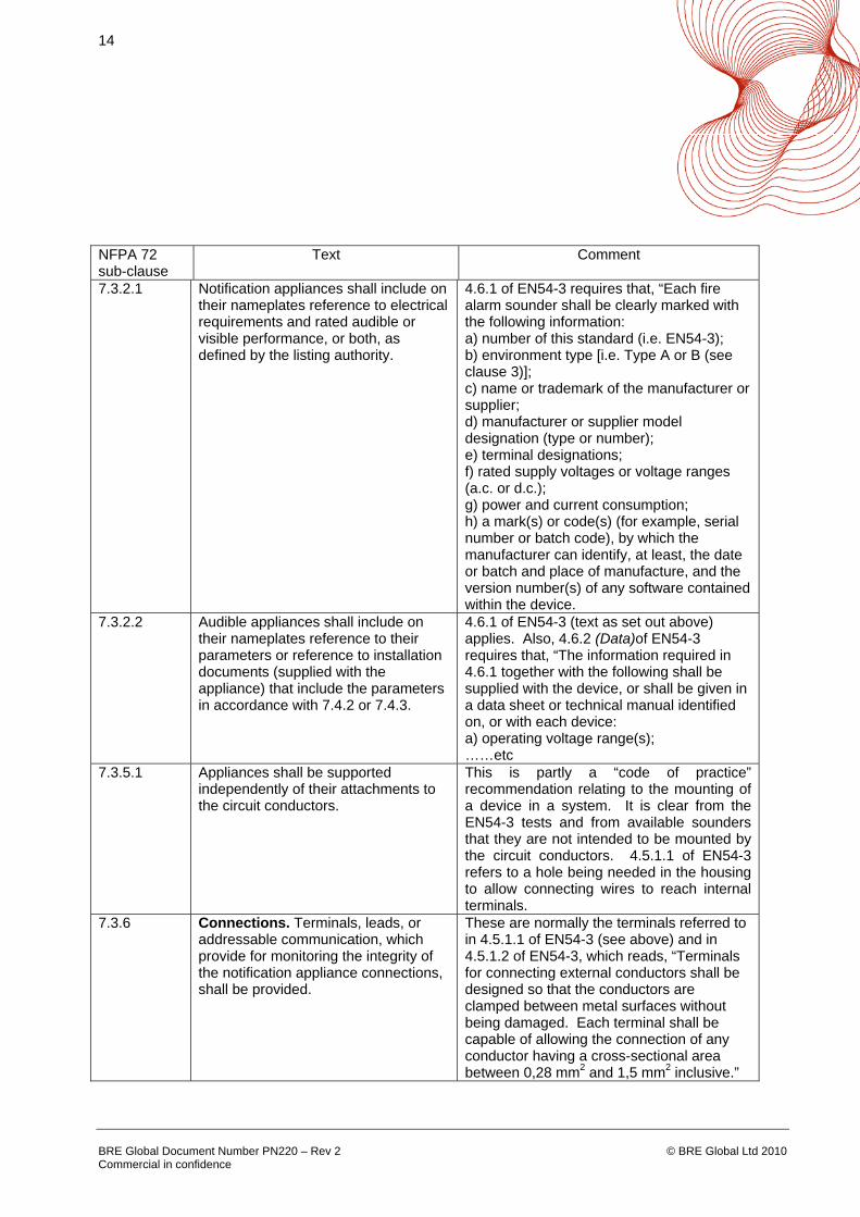
7.3.2.1 Notification appliances shall include on their nameplates reference to electrical requirements and rated audible or visible performance, or both, as defined by the listing authority.
4.6.1 of EN54-3 requires that, “Each fire alarm sounder shall be clearly marked with the following information: a) number of this standard (i.e. EN54-3); b) environment type [i.e. Type A or B (see clause 3)]; c) name or trademark of the manufacturer or supplier; d) manufacturer or supplier model designation (type or number); e) terminal designations; f) rated supply voltages or voltage ranges (a.c. or d.c.); g) power and current consumption; h) a mark(s) or code(s) (for example, serial number or batch code), by which the manufacturer can identify, at least, the date or batch and place of manufacture, and the version number(s) of any software contained within the device.
7.3.2.2 Audible appliances shall include on their nameplates reference to their parameters or reference to installation documents (supplied with the appliance) that include the parameters in accordance with 7.4.2 or 7.4.3.
4.6.1 of EN54-3 (text as set out above) applies. Also, 4.6.2 (Data)of EN54-3 requires that, “The information required in 4.6.1 together with the following shall be supplied with the device, or shall be given in a data sheet or technical manual identified on, or with each device: a) operating voltage range(s); ……etc
7.3.5.1 Appliances shall be supported independently of their attachments to the circuit conductors.
This is partly a “code of practice” recommendation relating to the mounting of a device in a system. It is clear from the EN54-3 tests and from available sounders that they are not intended to be mounted by the circuit conductors. 4.5.1.1 of EN54-3 refers to a hole being needed in the housing to allow connecting wires to reach internal terminals.
7.3.6 Connections. Terminals, leads, or addressable communication, which provide for monitoring the integrity of the notification appliance connections, shall be provided.
These are normally the terminals referred to in 4.5.1.1 of EN54-3 (see above) and in 4.5.1.2 of EN54-3, which reads, “Terminals for connecting external conductors shall be designed so that the conductors are clamped between metal surfaces without being damaged. Each terminal shall be capable of allowing the connection of any conductor having a cross-sectional area between 0,28 mm2 and 1,5 mm2 inclusive.”
15
BRE Global Document Number PN220 – Rev 2 Commercial in confidence
© BRE Global Ltd 2010
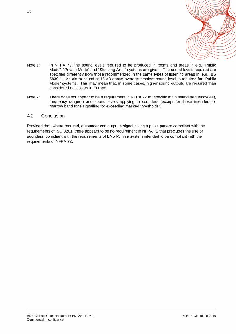
Note 1: In NFPA 72, the sound levels required to be produced in rooms and areas in e.g. “Public Mode”, “Private Mode” and “Sleeping Area” systems are given. The sound levels required are specified differently from those recommended in the same types of listening areas in, e.g., BS 5839-1. An alarm sound at 15 dB above average ambient sound level is required for “Public Mode” systems. This may mean that, in some cases, higher sound outputs are required than considered necessary in Europe.
Note 2: There does not appear to be a requirement in NFPA 72 for specific main sound frequency(ies),
frequency range(s) and sound levels applying to sounders (except for those intended for “narrow band tone signalling for exceeding masked thresholds”).
4.2 Conclusion
Provided that, where required, a sounder can output a signal giving a pulse pattern compliant with the requirements of ISO 8201, there appears to be no requirement in NFPA 72 that precludes the use of sounders, compliant with the requirements of EN54-3, in a system intended to be compliant with the requirements of NFPA 72.
16
BRE Global Document Number PN220 – Rev 2 Commercial in confidence
© BRE Global Ltd 2010
5. EN54-4: 1998 Power Supply Equipment
5.1 Key Requirements of NFPA 72
NFPA 72 sub-clause
Text Comment
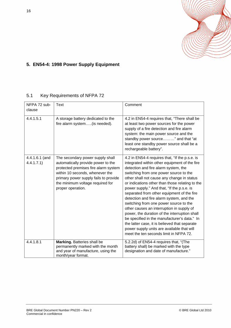
4.4.1.5.1 A storage battery dedicated to the fire alarm system…..(is needed).
4.2 in EN54-4 requires that, “There shall be at least two power sources for the power supply of a fire detection and fire alarm system: the main power source and the standby power source………” and that “at least one standby power source shall be a rechargeable battery”.
4.4.1.6.1 (and 4.4.1.7.1)
The secondary power supply shall automatically provide power to the protected premises fire alarm system within 10 seconds, whenever the primary power supply fails to provide the minimum voltage required for proper operation.
4.2 in EN54-4 requires that, “If the p.s.e. is integrated within other equipment of the fire detection and fire alarm system, the switching from one power source to the other shall not cause any change in status or indications other than those relating to the power supply.” And that, “If the p.s.e. is separated from other equipment of the fire detection and fire alarm system, and the switching from one power source to the other causes an interruption in supply of power, the duration of the interruption shall be specified in the manufacturer’s data.” In the latter case, it is believed that separate power supply units are available that will meet the ten seconds limit in NFPA 72.
4.4.1.8.1 Marking. Batteries shall be permanently marked with the month and year of manufacture, using the month/year format.
5.2.2d) of EN54-4 requires that, “(The battery shall) be marked with the type designation and date of manufacture.”

17
BRE Global Document Number PN220 – Rev 2 Commercial in confidence
© BRE Global Ltd 2010
NFPA 72 sub-clause
Text Comment
4.4.1.8.3.1 Adequate facilities shall be provided to automatically maintain the battery fully charged under all conditions of normal operation.
5.3.1 of EN54-4 requires that, “The charger shall be designed and rated so that: a) the battery can be charged automatically” and the power supply has to be tested to operate under “all conditions of normal operation” in the EN54-4 series of tests.
4.4.1.8.3.2 Adequate facilities shall be provided to recharge batteries within 48 hours after fully charged batteries have been subject to a single discharge cycle
5.3.1 b) of EN54-4 requires that, “a battery discharged to its final voltage can be recharged to at least 80 % of its rated capacity within 24 hours and to its rated capacity within another 48 hours;”
4.4.1.8.3.3 Upon attaining a fully charged condition, the charge rate shall not be so excessive as to result in battery damage.
This is not, as stated, a testable requirement. However, 5.3.1c) of EN54-4 requires that, “the charging characteristics are within the battery manufacturer’s specification over the ambient temperature range of the battery.”, which should include not damaging the battery.
4.4.1.8.3.4 Batteries shall be either trickle- or float-charged.
This choice is not referred to in EN54-4, but either could be used to meet the requirements of the standard. (Float-charging is considered to be the more usual.)
4.4.1.8.4.1 The batteries shall be protected against excessive load current by overcurrent devices.
6.3.1 of EN54-4 requires that, “All outputs shall have appropriate power limitation in order to ensure that in case of external short-circuits no danger exists because of heat production.
4.4.1.8.4.2 The batteries shall be protected from excessive charging current by overcurrent devices or by automatic current-limiting design of the charging source.
This does not appear to be stated explicitly in EN54-4. Protection is normally by automatic current-limiting design.
4.4.1.8.5 Metering. The charging equipment shall provide either integral meters or readily accessible terminal facilities for the connection of portable meters by which the battery voltage and charging current can be determined.
This is not listed as a requirement in EN54-4 but, in practice, battery terminals are normally readily accessible for connection of voltmeters or ammeters.

18
BRE Global Document Number PN220 – Rev 2 Commercial in confidence
© BRE Global Ltd 2010
NFPA 72 sub-clause
Text Comment
4.4.1.8.6 Charger Supervision. Supervision means appropriate for the batteries and charger employed shall be provided to detect a failure of battery charging and initiate a trouble signal in accordance with 4.4.3.5.
5.4d) of EN54-4 requires that, “(The p.s.e. shall be capable of recognizing and signalling the following faults:) loss of the battery charger, within 30 minutes of the occurrence.” This response time is outside of the limit required in 4.4.3.5 of NFPA 72 (200 seconds), but, in practice, failure of a battery charger is normally indicated within 200 seconds of occurrence.
4.4.7.3.1 Unless otherwise permitted or required by 4.4.7.3.1.1 through 4.4.7.3.1.4, all primary and secondary power supplies shall be monitored for the presence of voltage at the point of connection to the system. Failure of either supply shall result in a trouble signal in accordance with 4.4.3.5.
This is partly a requirement for control and indicating equipment to indicate the presence of power. (See EN54-2.) However, with regard to failure of either supply, 5.4 of EN54-4 requires that, “The p.s.e. shall be capable of recognizing and signalling the following faults: a) loss of the main power source, within 30 minutes of the occurrence; b) loss of the standby power source, within 15 minutes of the occurrence; c) reduction of the battery voltage to less than 0,9 of the final voltage, within 30 minutes of the occurrence;”. These response times are outside of the limits required in 4.4.3.5 of NFPA 72 (200 seconds), but, in practice, these faults are normally indicated within 200 seconds of occurrence.
Note 1: It has been assumed that the power supplies covered by this section are of the type suitable for fire alarm systems for protected premises, rather than domestic fire alarm systems.
5.2 Conclusion
Provided that actual response times for indication of the fault conditions referred to in 4.4.1.8.6 and 4.4.7.3.1 of NFPA 72 are declared by the power supply’s manufacturer to be less than 200 seconds (i.e. compliant with 4.4.3.5 of NFPA 72), there appears to be no requirement in NFPA 72 that precludes the use of power supply equipment, compliant with the requirements of EN54-4, in a system intended to be compliant with the requirements of NFPA 72.
19
BRE Global Document Number PN220 – Rev 2 Commercial in confidence
© BRE Global Ltd 2010
6. EN54-5: 2001 Heat Detectors – Point Detectors
6.1 Key Requirements of NFPA 72
NFPA 72 sub-clause
Text Comment
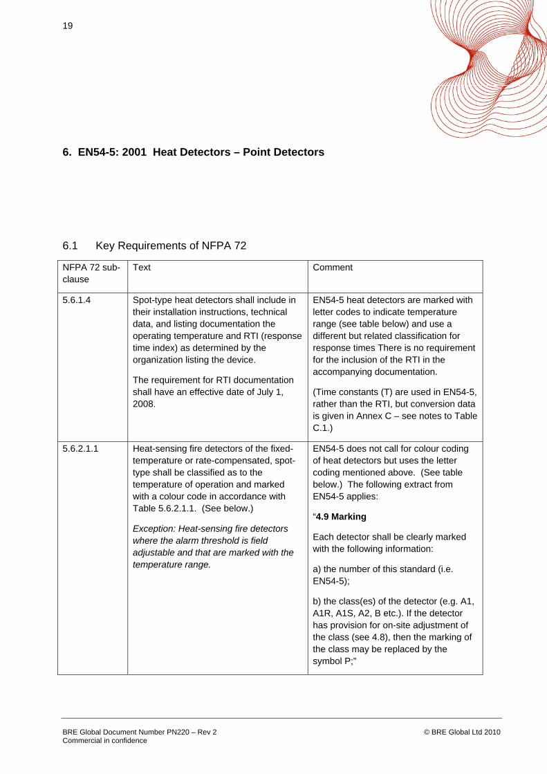
5.6.1.4 Spot-type heat detectors shall include in their installation instructions, technical data, and listing documentation the operating temperature and RTI (response time index) as determined by the organization listing the device.
The requirement for RTI documentation shall have an effective date of July 1, 2008.
EN54-5 heat detectors are marked with letter codes to indicate temperature range (see table below) and use a different but related classification for response times There is no requirement for the inclusion of the RTI in the accompanying documentation.
(Time constants (T) are used in EN54-5, rather than the RTI, but conversion data is given in Annex C – see notes to Table C.1.)
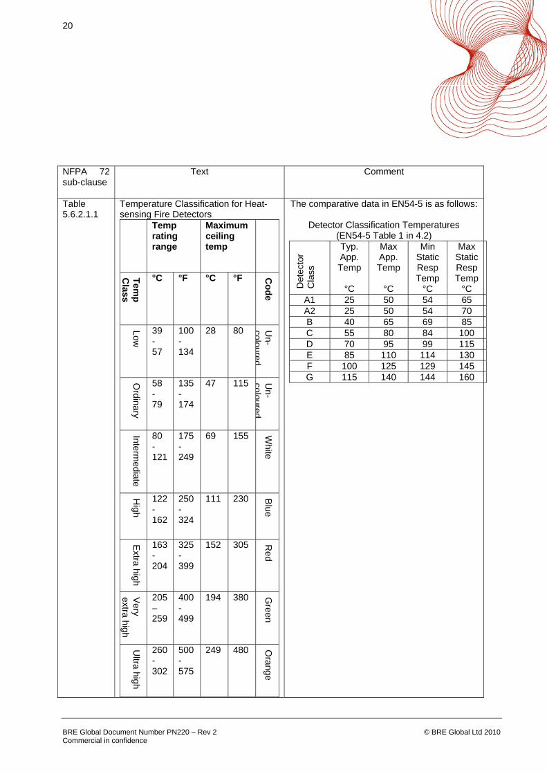
5.6.2.1.1 Heat-sensing fire detectors of the fixed-temperature or rate-compensated, spot-type shall be classified as to the temperature of operation and marked with a colour code in accordance with Table 5.6.2.1.1. (See below.)
Exception: Heat-sensing fire detectors where the alarm threshold is field adjustable and that are marked with the temperature range.
EN54-5 does not call for colour coding of heat detectors but uses the letter coding mentioned above. (See table below.) The following extract from EN54-5 applies:
“4.9 Marking
Each detector shall be clearly marked with the following information:
a) the number of this standard (i.e. EN54-5);
b) the class(es) of the detector (e.g. A1, A1R, A1S, A2, B etc.). If the detector has provision for on-site adjustment of the class (see 4.8), then the marking of the class may be replaced by the symbol P;”
20
BRE Global Document Number PN220 – Rev 2 Commercial in confidence
© BRE Global Ltd 2010
NFPA 72 sub-clause
Text Comment
Table 5.6.2.1.1
Temperature Classification for Heat-sensing Fire Detectors
Temp rating range
Maximum ceiling temp
Temp
Class
°C °F °C °F Code
Low
39 - 57
100-134
28 80 Un-
coloured
Ordinary
58 - 79
135-174
47 115 Un-
coloured
Intermediate
80 -121
175-249
69 155 White
High
122-162
250-324
111 230 Blue
Extra high
163-204
325-399
152 305 Red
Very
extra high
205–259
400-499
194 380 Green
Ultra high
260-302
500-575
249 480 Orange
The comparative data in EN54-5 is as follows:
Detector Classification Temperatures (EN54-5 Table 1 in 4.2)
Det
ecto
r C
lass
Typ. App. Temp
°C
Max App. Temp
°C
Min Static Resp Temp
°C
Max Static Resp Temp
°C A1 25 50 54 65 A2 25 50 54 70 B 40 65 69 85 C 55 80 84 100 D 70 95 99 115 E 85 110 114 130 F 100 125 129 145 G 115 140 144 160

21
BRE Global Document Number PN220 – Rev 2 Commercial in confidence
© BRE Global Ltd 2010
6.2 Conclusion
Provided that the EN54-5 temperature classification letter codes are considered equivalent to the colour coding required by NFPA 72, and it is accepted that the RTI can be calculated, if required, from manufacturer’s data, there appears to be no requirement in NFPA 72 that precludes the use of heat detectors, compliant with the requirements of EN54-5, in a system intended to be compliant with the requirements of NFPA 72.
22
BRE Global Document Number PN220 – Rev 2 Commercial in confidence
© BRE Global Ltd 2010
7. EN54-7: 2001 Smoke Detectors – Point Detectors Using Scattered Light or Ionization
7.1 Key Requirements of NFPA 72
NFPA 72 sub-clause
Text Comment
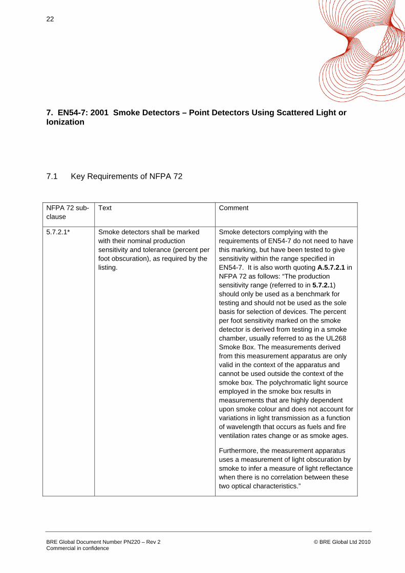
5.7.2.1* Smoke detectors shall be marked with their nominal production sensitivity and tolerance (percent per foot obscuration), as required by the listing.
Smoke detectors complying with the requirements of EN54-7 do not need to have this marking, but have been tested to give sensitivity within the range specified in EN54-7. It is also worth quoting A.5.7.2.1 in NFPA 72 as follows: “The production sensitivity range (referred to in 5.7.2.1) should only be used as a benchmark for testing and should not be used as the sole basis for selection of devices. The percent per foot sensitivity marked on the smoke detector is derived from testing in a smoke chamber, usually referred to as the UL268 Smoke Box. The measurements derived from this measurement apparatus are only valid in the context of the apparatus and cannot be used outside the context of the smoke box. The polychromatic light source employed in the smoke box results in measurements that are highly dependent upon smoke colour and does not account for variations in light transmission as a function of wavelength that occurs as fuels and fire ventilation rates change or as smoke ages.
Furthermore, the measurement apparatus uses a measurement of light obscuration by smoke to infer a measure of light reflectance when there is no correlation between these two optical characteristics.”
23
BRE Global Document Number PN220 – Rev 2 Commercial in confidence
© BRE Global Ltd 2010
NFPA 72 sub-clause
Text Comment
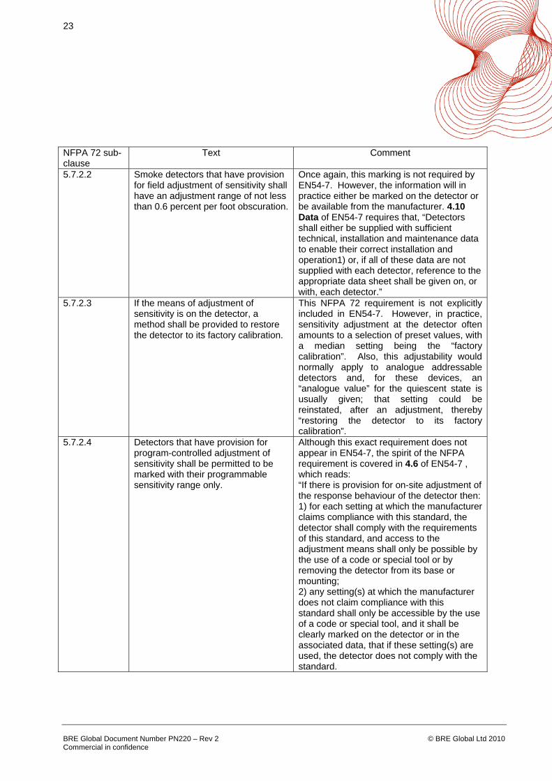
5.7.2.2 Smoke detectors that have provision for field adjustment of sensitivity shall have an adjustment range of not less than 0.6 percent per foot obscuration.
Once again, this marking is not required by EN54-7. However, the information will in practice either be marked on the detector or be available from the manufacturer. 4.10 Data of EN54-7 requires that, “Detectors shall either be supplied with sufficient technical, installation and maintenance data to enable their correct installation and operation1) or, if all of these data are not supplied with each detector, reference to the appropriate data sheet shall be given on, or with, each detector.”
5.7.2.3 If the means of adjustment of sensitivity is on the detector, a method shall be provided to restore the detector to its factory calibration.
This NFPA 72 requirement is not explicitly included in EN54-7. However, in practice, sensitivity adjustment at the detector often amounts to a selection of preset values, with a median setting being the “factory calibration”. Also, this adjustability would normally apply to analogue addressable detectors and, for these devices, an “analogue value” for the quiescent state is usually given; that setting could be reinstated, after an adjustment, thereby “restoring the detector to its factory calibration”.
5.7.2.4 Detectors that have provision for program-controlled adjustment of sensitivity shall be permitted to be marked with their programmable sensitivity range only.
Although this exact requirement does not appear in EN54-7, the spirit of the NFPA requirement is covered in 4.6 of EN54-7 , which reads: “If there is provision for on-site adjustment of the response behaviour of the detector then: 1) for each setting at which the manufacturer claims compliance with this standard, the detector shall comply with the requirements of this standard, and access to the adjustment means shall only be possible by the use of a code or special tool or by removing the detector from its base or mounting; 2) any setting(s) at which the manufacturer does not claim compliance with this standard shall only be accessible by the use of a code or special tool, and it shall be clearly marked on the detector or in the associated data, that if these setting(s) are used, the detector does not comply with the standard.

24
BRE Global Document Number PN220 – Rev 2 Commercial in confidence
© BRE Global Ltd 2010
NFPA 72 sub-clause
Text Comment
A.5.7.1.8 Product-listing standards include tests for temporary excursions beyond normal limits. In addition to temperature, humidity, and velocity variations, smoke detectors should operate reliably under such common environmental conditions as mechanical vibration, electrical interference, and other environmental influences. Tests for these conditions are also conducted by the testing laboratories in their listing program. In those cases in which environmental conditions approach the limits shown in Table A.5.7.1.8, the detector manufacturer’s published instructions should be consulted for additional information and recommendations.
EN54-7 includes all these tests, and manufacturers publish further information.
7.2 Conclusion
Provided that information is made available by the manufacturer, as discussed in 7.1 above, there appears to be no requirement in NFPA 72 that precludes the use of point smoke detectors, using scattered light, transmitted light or ionization, compliant with the requirements of EN54-7, in a system intended to be compliant with the requirements of NFPA 72.
25
BRE Global Document Number PN220 – Rev 2 Commercial in confidence
© BRE Global Ltd 2010
8. EN54-10: 2002 Flame Detectors
8.1 Key Requirements of NFPA 72
NFPA 72 sub-clause
Text Comment
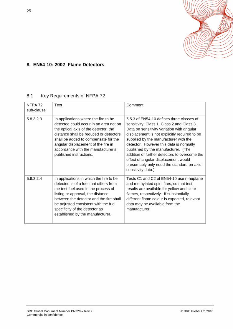
5.8.3.2.3 In applications where the fire to be detected could occur in an area not on the optical axis of the detector, the distance shall be reduced or detectors shall be added to compensate for the angular displacement of the fire in accordance with the manufacturer’s published instructions.
5.5.3 of EN54-10 defines three classes of sensitivity: Class 1, Class 2 and Class 3. Data on sensitivity variation with angular displacement is not explicitly required to be supplied by the manufacturer with the detector. However this data is normally published by the manufacturer. (The addition of further detectors to overcome the effect of angular displacement would presumably only need the standard on-axis sensitivity data.)
5.8.3.2.4 In applications in which the fire to be detected is of a fuel that differs from the test fuel used in the process of listing or approval, the distance between the detector and the fire shall be adjusted consistent with the fuel specificity of the detector as established by the manufacturer.
Tests C1 and C2 of EN54-10 use n-heptane and methylated spirit fires, so that test results are available for yellow and clear flames, respectively. If substantially different flame colour is expected, relevant data may be available from the manufacturer.

26
BRE Global Document Number PN220 – Rev 2 Commercial in confidence
© BRE Global Ltd 2010
NFPA 72 sub-clause
Text Comment
Table 10.4.2.2.14 f)
Flame detectors and spark/ember detectors shall be tested in accordance with the manufacturer’s published instructions to determine that each detector is operative. Flame detector and spark/ember detector sensitivity shall be determined using any of the following: (1) Calibrated test method (2) Manufacturer’s calibrated sensitivity test instrument (3) Listed control unit arranged for the purpose (4) Other approved calibrated sensitivity test method that is directly proportional to the input signal from a fire, consistent with the detector listing or approval. If designed to be field adjustable, detectors found to be outside of the approved range of sensitivity shall be replaced or adjusted to bring them into the approved range. Flame detector and spark/ember detector sensitivity shall not be determined using a light source that administers an unmeasured quantity of radiation at an undefined distance from the detector.
4.8 (Data) of EN54-10 states that, “Detectors shall either be supplied with sufficient technical, installation and maintenance data to enable their correct installation and operation1) or, if all of these data are not supplied with each detector, reference to the appropriate data sheet shall be given on, or with each detector.” There is no explicit requirement in EN54-10 for a measurement of device sensitivity to be made, since normally this is preset, e.g., as Class 1. Where sensitivity can be adjusted in the field, manufacturers are required by 4.7 of EN54-10 to allow adjustment within the defined sensitivity Classes, except that “any setting(s), at which the manufacturer does not claim compliance with this standard, shall only be accessible by the use of a code or special tool, and it shall be clearly marked on the detector or in the associated data, that if these setting(s) are used, the detector does not comply with the standard.”.
8.2 Conclusion Provided that, where required by NFPA 72 for a particular application, the data referred to in 8.1 above is available, there appears to be no requirement in NFPA 72 that precludes the use of flame detectors, compliant with the requirements of EN54-10, in a system intended to be compliant with the requirements of NFPA 72.
27
BRE Global Document Number PN220 – Rev 2 Commercial in confidence
© BRE Global Ltd 2010
9. EN54-11: 2001 Manual Call Points
9.1 Key Requirements of NFPA 72 NFPA 72 sub-clause
Text Comment
3.3.63.3 A manually operated device used to initiate an alarm signal.
This is the definition of a manual call point as understood in EN54-11.
9.4.2.1.2 The box housing shall protect the external components from the weather.
This requirement relates to McCulloh systems. However, EN54-11, in 5.19, specifies tests for adequate enclosure protection (and, if required IP 67 versions of manual call points are available).
9.4.2.1.4 Boxes shall be recognizable as such and shall have instructions for use plainly marked on their exterior surfaces.
This requirement also relates to McCulloh systems. However, EN54-11 includes marking requirements for manual call points that will render them conspicuous and recognizable.
Note 1: A.5.13.5 of NFPA 72 requires that, “Manual fire alarm boxes shall be of contrasting colour to the background on which they are mounted.” This is really a “code of practice” recommendation, but the requirement of 4.7.2.3 of EN54-11 for a manual call point to be red in colour should normally enable the NFPA 72 “requirement” to be met. Note 2: 9.4.2.1.8 of NFPA 72 requires that, “Boxes shall be conspicuously visible and be highlighted with a distinctive colour.” This is another McCulloh system requirement but would again be met by the red colour required in EN54-11 for manual call points. 9.2 Conclusion There appears to be no requirement in NFPA 72 that precludes the use of manual call points, compliant with the requirements of EN54-11, in a system intended to be compliant with the requirements of NFPA 72.
28
BRE Global Document Number PN220 – Rev 2 Commercial in confidence
© BRE Global Ltd 2010
10. EN54-12: 2002 Smoke Detectors – Line Detectors Using an Optical Beam
10.1 Key Requirements of NFPA 72
NFPA 72 sub-clause
Text Comment
5.7.3.4 Projected Beam Type Smoke Detectors
The location and spacing requirements of 5.7.3.4.1 to 5.7.3.4.8 all relate to applications of the detectors in systems and not directly to their performance.
A.5.7.3.4.8 Where the light path of a projected beam–type detector is abruptly interrupted or obscured, the unit should not initiate an alarm. It should give a trouble signal after verification of blockage.
Test number 5.6 of EN54-12 requires emission of either a fault or a fire signal after a rapid change in attenuation of the light beam. However, normally, beam smoke detectors are specified to give a fault signal (and not a fire signal) on abrupt interruption of the light beam.
10.2 Conclusion
Provided that the manufacturer of the beam smoke detector specifies and declares that an abrupt interruption of the beam will cause a fault signal and not a fire signal to be emitted, there appears to be no requirement in NFPA 72 that precludes the use of beam smoke detectors (projected beam-type detectors), compliant with the requirements of EN54-12, in a system intended to be compliant with the requirements of NFPA 72.

29
BRE Global Document Number PN220 – Rev 2 Commercial in confidence
© BRE Global Ltd 2010
11. EN54-17: 2005 Short Circuit Isolators
11.1 Key Requirements of NFPA 72
There appear to be only a few references in NFPA 72 to the use of short-circuit isolators. For example, one method of helping to ensure that sounders in one zone will continue to operate when there is a fire condition in a different zone is to use “short-circuit fault-tolerant signalling line circuits for controlling evacuation signals”. All such references identified are to applications of short-circuit isolators and no specific requirements for characteristics of the devices themselves could be found.
11.2 Conclusion
There appears to be no requirement in NFPA 72 that precludes the use of short-circuit isolators, compliant with the requirements of EN54-17, in a system intended to be compliant with the requirements of NFPA 72.
30
BRE Global Document Number PN220 – Rev 2 Commercial in confidence
© BRE Global Ltd 2010
12. EN54-18: 2005 Input/Output Devices
12.1 Key Requirements of NFPA 72
There are references in NFPA 72 to “signalling line circuit interfaces” and to “supervisory signal-initiating devices”, e.g. associated with sprinkler flow switches, but only in that they may be used to receive inputs from initiating devices or provide outputs to such auxiliary equipment as lift and HVAC control, as appropriate. No specific requirements for characteristics of input/output devices could be found.
12.2 Conclusion
There appears to be no requirement in NFPA 72 that precludes the use of input/output devices, compliant with the requirements of EN54-18, in a system intended to be compliant with the requirements of NFPA 72.

31
BRE Global Document Number PN220 – Rev 2 Commercial in confidence
© BRE Global Ltd 2010
13. Approvals, Listings and General Comments
13.1 NFPA 72 does not restrict the designer to only using products that are tested and listed to US standards. This is confirmed by the following statement in NFPA 72 sub-clause 1.5.1 “Nothing in this Code shall prevent the use of systems, methods, devices or appliances of equivalent or superior quality, strength, fire resistance, effectiveness, durability and safety over those prescribed by this code”.
13.2 NFPA 72 does not specify that fire alarm system components need to be covered by specific standards, such as ANSI/UL 268 for smoke detectors, even though the content of such standards had been used in the preparation of that Code. This is confirmed by the following statement given in F.2 of NFPA 72. “Standards and Codes. The following standards and codes are referenced explicitly or implicitly regarding the design, installation, testing, maintenance, and use of these systems and their components. These were used when developing this standard, but are not necessarily required practice for manufacturers.” (A list of North American standards then follows in the document.)
13.3 The Code does require that equipment used in the design and installation of the fire detection and alarm system is listed and this is confirmed by the statement in NFPA 72 sub-clause 4.3.1 - “Equipment constructed and installed in conformity with this Code shall be listed for the purpose for which it is used. Fire alarm system components shall be installed, tested, and maintained in accordance with the manufacturer’s instructions and this Code”.
13.4 The Code allows for any accredited listing or approvals bodies to verify conformity of equipment to appropriate standards. This is confirmed by the following definition in NFPA 72 sub-clause 3.2.5 which defines listed as - “Equipment materials or services included in a list published by an organization that is acceptable to the authority having jurisdiction and concerned with evaluation of products or services, that maintains periodic inspection of production of listed equipment or materials or periodic evaluation of services, and whose listing states that either the equipment, material, or service meets appropriate designated standards or has been tested and found suitable for a specified purpose”
13.5 It has been assumed that the fire detection and fire alarm systems relevant to this assessment would primarily be “Protected Premises Fire Alarm Systems” as defined in NFPA 72. Specific requirements for “Supervising Station Fire Alarm Systems”, “Public Fire Alarm Reporting Systems” and “Single- and Multiple-Station Alarms and Household Fire Alarm Systems” have been observed but generally not considered for detailed compatibility with the requirements of the relevant EN54 series standards.
32
BRE Global Document Number PN220 – Rev 2 Commercial in confidence
© BRE Global Ltd 2010
14. Conclusions
14.1 There appear to be no major differences, which cannot be overcome, between the requirements of NFPA 72 and those of the relevant parts of EN54. This means that products compliant with EN54-2, EN54-3, EN54-4, EN54-5, EN54-7, EN54-10, EN54-11, EN54-12, EN54-17 and EN54-18 should be usable in systems required to comply with the requirements of NFPA 72.
14.2 Of the EN54 series standards assessed, EN54-2 for control and indicating equipment has the highest potential for non-compliance with NFPA 72. However, even in this case, reference to Section 3 above will show that it is merely necessary for the manufacturer to check which of the requirements apply to a particular system, and then to ensure that the appropriate product data is provided to ensure compliance.
14.3 It is not sufficient for a product that will be used within an NFPA 72 installation to claim compliance to the requirements of the Code; it must prove that it complies by having the necessary approval from a third party certification body to the appropriate product standard and being listed by that body.