Report on Proposals A2008 — Copyright, NFPA NFPA 1901 · Report on Proposals A2008 — Copyright,...
109
1901-67 Report on Proposals A2008 — Copyright, NFPA NFPA 1901 DRAFT NFPA 1901 Standard for Automotive Fire Apparatus 2009 Edition IMPORTANT NOTE: This NFPA document is made available for use subject to important notices and legal disclaimers. These notices and disclaimers appear in all publications containing this document and may be found under the heading “Important Notices and Disclaimers Concerning NFPA Documents.” They can also be obtained on request from NFPA or viewed at www.nfpa.org/disclaimers. NOTICE: An asterisk (*) following the number or letter designating a paragraph indicates that explanatory material on the paragraph can be found in Annex A. A reference in brackets [ ] following a section or paragraph indicates material that has been extracted from another NFPA document. As an aid to the user, Annex F lists the complete title and edition of the source documents for both mandatory and nonmandatory extracts. Editorial changes to extracted material consist of revising references to an appropriate division in this document or the inclusion of the document number with the division number when the reference is to the original document. Requests for interpretations or revisions of extracted text shall be sent to the technical committee responsible for the source document. Information on referenced publications can be found in Chapter 2 and Annex F. Chapter 1 Administration 1.1* Scope. This standard defines the requirements for new automotive fire apparatus and trailers designed to be used under emergency conditions to transport personnel and equipment and to support the suppression of fires and mitigation of other hazardous situations. 1.2 Purpose. This standard specifies the minimum requirements for new automotive fire apparatus and trailers. 1.3 Application. 1.3.1* This standard shall apply to new fire apparatus that meet the following criteria: (1) That are of 10,000 lb (4500 kg) or greater gross vehicle weight rating (GVWR), or trailers intended to be towed by fire apparatus under emergency response conditions (2) That are designed for use under emergency conditions to transport personnel and equipment and to support the suppression of fires and mitigation of other hazardous situations (3) That are contracted for on or after January 1, 2009 1.3.2 Nothing shall prevent the use of the standard prior to January 1, 2009, if the purchaser and the contractor both agree. 1.3.3 This standard shall not apply to wildland fire apparatus, which are covered by NFPA 1906, Standard for Wildland Fire Apparatus. 1.4* Retroactivity. This standard shall not be applied retroactively. 1.5 Equivalency. Nothing in this standard is intended to prevent the use of systems, methods, or devices of equivalent or superior quality, strength, fire resistance, effectiveness, durability, and safety over those prescribed by this standard. 1.5.1 The technical documentation shall be submitted to the authority having jurisdiction to demonstrate equivalency. 1.5.2 The system, method, or device shall be approved for the intended purpose by the authority having jurisdiction.. 1.6* Units and Formulas. In this standard, values for measurement in U.S. units are followed by equivalents in SI units. Either set of values can be used, but the same set of values (either U.S. units or SI units) shall be used consistently. Chapter 2 Referenced Publications 2.1 General. The documents or portions thereof listed in this chapter are referenced within this standard and shall be considered part of the requirements of this document. 2.2 NFPA Publications. National Fire Protection Association, 1 Batterymarch Park, Quincy, MA 02169-7471. NFPA 70, National Electrical Code ® , 2005 edition. NFPA 1002, Standard for Fire Apparatus Driver/Operator Professional Qualifications, 2003 edition. NFPA 1500, Standard on Fire Department Occupational Safety and Health Program, 2007 edition. NFPA 1911, Standard for the Inspection, Maintenance, Testing, and Retirement of In-Service Automotive Fire Apparatus, 2007 edition. NFPA 1931, Standard on Design of and Design Verification Tests for Fire Department Ground Ladders, 2004 edition. NFPA 1961, Standard on Fire Hose, 2007 edition. NFPA 1963, Standard for Fire Hose Connections, 2003 edition. NFPA 1981, Standard on Open-Circuit Self-Contained Breathing Apparatus for Fire and Emergency Services, 2007 edition. NFPA 1983, Standard on Fire Service Life Safety Rope and System Components, 2006 edition. NFPA 1989, Standard on Breathing Air Quality for Fire and Emergency Services Respiratory Protection, 2003 edition. 2.3 Other Publications. 2.3.1 ANSI Publications. American National Standards Institute, Inc., 11 West 42nd Street, 13th floor, New York, NY 10036. ANSI Z535.4, Product Safety Signs and Labels, 2002. 2.3.2 ASME Publications. American Society of Mechanical Engineers, Three Park Avenue, New York, NY 10016-5990. ASME Boiler and Pressure Vessel Code, Section VIII, Division 1 and Division 2, 2007. ASME B40.100, Pressure Gauges and Gauge Attachments, 2005. 2.3.3 ASNT Publication. American Society for Nondestructive Testing, Inc., 1711 Arlingate Lane, Columbus, OH 43228-0518. ASNT CP-189, Standard for Qualification and Certification of Nondestructive Testing Personnel, 2006. 2.3.4 ASTM Publications. American Society for Testing and Materials, 100 Barr Harbor Drive, West Conshohocken, PA 19428-2959. ASTM B 647, Standard Test Method for Indentation Hardness of Aluminum Alloys by Means of a Webster Hardness Gage, 1984 (reconfirmed 2006). ASTM B 648, Standard Test Method for Indentation Hardness of Aluminum Alloys by Means of a Barcol Impressor, 1978 (reconfirmed 2006). ASTM D 4956, Standard Specification for Retroreflective Sheeting for Traffic Control, 2005. ASTM E 6, Standard Terminology Relating to Methods of Mechanical Testing, 2006. ASTM E 10, Standard Test Method for Brinell Hardness of Metallic Materials, 2007. ASTM E 18, Standard Test Methods for Rockwell Hardness and Rockwell Superficial Hardness of Metallic Materials, 2005. ASTM E 92, Standard Test Method for Vickers Hardness of Metallic Materials, 1982 (reconfirmed 2003). ASTM E 114, Standard Practice for Ultrasonic Pulse-Echo Straight-Beam Examination by the Contact Method, 1995 (reconfirmed 2005). ASTM E 165, Standard Test Method for Liquid Penetrant Examinations, 2002. ASTM E 569, Standard Practice for Acoustic Emission Monitoring of Structures During Controlled Stimulation, 2002. ASTM E 650, Standard Guide for Mounting Piezoelectric Acoustic Emission Sensors, 1997 (reconfirmed 2002). ASTM E 709, Standard Guide for Magnetic Particle Examination, 2001. ASTM E 797, Standard Practice for Measuring Thickness by Manual Ultrasonic Pulse-Echo Contact Method, 2005 ASTM E 1004, Standard Practice for Determining Electrical Conductivity Using the Electromagnetic (Eddy-Current) Method, 2002. ASTM F 1677, Standard Test Method for Using a Portable Inclinable Articulated Strut Slip Tester (PIAST) , 1996. ASTM F 1679, Standard Test Method for Using a Variable Incidence Tribometer (VIT) , 2000.
-
Upload
duongtuyen -
Category
Documents
-
view
252 -
download
2
Transcript of Report on Proposals A2008 — Copyright, NFPA NFPA 1901 · Report on Proposals A2008 — Copyright,...

1901-67
Report on Proposals A2008 — Copyright, NFPA NFPA 1901
DRAFT
NFPA 1901 Standard for
Automotive Fire Apparatus 2009 Edition
IMPORTANT NOTE: This NFPA document is made available for use subject to important notices and legal disclaimers. These notices and disclaimers appear in all publications containing this document and may be found under the heading “Important Notices and Disclaimers Concerning NFPA Documents.” They can also be obtained on request from NFPA or viewed at www.nfpa.org/disclaimers.
NOTICE: An asterisk (*) following the number or letter designating a paragraph indicates that explanatory material on the paragraph can be found in Annex A.
A reference in brackets [ ] following a section or paragraph indicates material that has been extracted from another NFPA document. As an aid to the user, Annex F lists the complete title and edition of the source documents for both mandatory and nonmandatory extracts. Editorial changes to extracted material consist of revising references to an appropriate division in this document or the inclusion of the document number with the division number when the reference is to the original document. Requests for interpretations or revisions of extracted text shall be sent to the technical committee responsible for the source document.
Information on referenced publications can be found in Chapter 2 and Annex F.
Chapter 1 Administration
1.1* Scope. This standard defines the requirements for new automotive fire apparatus and trailers designed to be used under emergency conditions to transport personnel and equipment and to support the suppression of fires and mitigation of other hazardous situations.
1.2 Purpose. This standard specifies the minimum requirements for new automotive fire apparatus and trailers.
1.3 Application.
1.3.1* This standard shall apply to new fire apparatus that meet the following criteria: (1) That are of 10,000 lb (4500 kg) or greater gross vehicle weight rating (GVWR), or trailers intended to be towed by fire apparatus under emergency response conditions
(2) That are designed for use under emergency conditions to transport personnel and equipment and to support the suppression of fires and mitigation of other hazardous situations
(3) That are contracted for on or after January 1, 2009
1.3.2 Nothing shall prevent the use of the standard prior to January 1, 2009, if the purchaser and the contractor both agree.
1.3.3 This standard shall not apply to wildland fire apparatus, which are covered by NFPA 1906, Standard for Wildland Fire Apparatus.
1.4* Retroactivity. This standard shall not be applied retroactively.
1.5 Equivalency. Nothing in this standard is intended to prevent the use of systems, methods, or devices of equivalent or superior quality, strength, fire resistance, effectiveness, durability, and safety over those prescribed by this standard.
1.5.1 The technical documentation shall be submitted to the authority having jurisdiction to demonstrate equivalency.
1.5.2 The system, method, or device shall be approved for the intended purpose by the authority having jurisdiction..
1.6* Units and Formulas. In this standard, values for measurement in U.S. units are followed by equivalents in SI units. Either set of values can be used, but the same set of values (either U.S. units or SI units) shall be used consistently.
Chapter 2 Referenced Publications
2.1 General. The documents or portions thereof listed in this chapter are referenced within this standard and shall be considered part of the requirements of this document.
2.2 NFPA Publications. National Fire Protection Association, 1 Batterymarch Park, Quincy, MA 02169-7471.
NFPA 70, National Electrical Code®, 2005 edition.
NFPA 1002, Standard for Fire Apparatus Driver/Operator Professional
Qualifications, 2003 edition.
NFPA 1500, Standard on Fire Department Occupational Safety and Health Program, 2007 edition.
NFPA 1911, Standard for the Inspection, Maintenance, Testing, and Retirement of In-Service Automotive Fire Apparatus, 2007 edition.
NFPA 1931, Standard on Design of and Design Verification Tests for Fire Department Ground Ladders, 2004 edition.
NFPA 1961, Standard on Fire Hose, 2007 edition.
NFPA 1963, Standard for Fire Hose Connections, 2003 edition.
NFPA 1981, Standard on Open-Circuit Self-Contained Breathing Apparatus for Fire and Emergency Services, 2007 edition.
NFPA 1983, Standard on Fire Service Life Safety Rope and System Components, 2006 edition.
NFPA 1989, Standard on Breathing Air Quality for Fire and Emergency Services Respiratory Protection, 2003 edition.
2.3 Other Publications.
2.3.1 ANSI Publications. American National Standards Institute, Inc., 11 West 42nd Street, 13th floor, New York, NY 10036.
ANSI Z535.4, Product Safety Signs and Labels, 2002.
2.3.2 ASME Publications. American Society of Mechanical Engineers, Three Park Avenue, New York, NY 10016-5990.
ASME Boiler and Pressure Vessel Code, Section VIII, Division 1 and Division 2, 2007.
ASME B40.100, Pressure Gauges and Gauge Attachments, 2005.
2.3.3 ASNT Publication. American Society for Nondestructive Testing, Inc., 1711 Arlingate Lane, Columbus, OH 43228-0518.
ASNT CP-189, Standard for Qualification and Certification of Nondestructive Testing Personnel, 2006.
2.3.4 ASTM Publications. American Society for Testing and Materials, 100 Barr Harbor Drive, West Conshohocken, PA 19428-2959.
ASTM B 647, Standard Test Method for Indentation Hardness of Aluminum Alloys by Means of a Webster Hardness Gage, 1984 (reconfirmed 2006).
ASTM B 648, Standard Test Method for Indentation Hardness of Aluminum Alloys by Means of a Barcol Impressor, 1978 (reconfirmed 2006).
ASTM D 4956, Standard Specification for Retroreflective Sheeting for Traffic Control, 2005.
ASTM E 6, Standard Terminology Relating to Methods of Mechanical Testing, 2006.
ASTM E 10, Standard Test Method for Brinell Hardness of Metallic Materials, 2007.
ASTM E 18, Standard Test Methods for Rockwell Hardness and Rockwell Superficial Hardness of Metallic Materials, 2005.
ASTM E 92, Standard Test Method for Vickers Hardness of Metallic Materials, 1982 (reconfirmed 2003).
ASTM E 114, Standard Practice for Ultrasonic Pulse-Echo Straight-Beam Examination by the Contact Method, 1995 (reconfirmed 2005).
ASTM E 165, Standard Test Method for Liquid Penetrant Examinations, 2002.
ASTM E 569, Standard Practice for Acoustic Emission Monitoring of Structures During Controlled Stimulation, 2002.
ASTM E 650, Standard Guide for Mounting Piezoelectric Acoustic Emission Sensors, 1997 (reconfirmed 2002).
ASTM E 709, Standard Guide for Magnetic Particle Examination, 2001.
ASTM E 797, Standard Practice for Measuring Thickness by Manual Ultrasonic Pulse-Echo Contact Method, 2005
ASTM E 1004, Standard Practice for Determining Electrical Conductivity Using the Electromagnetic (Eddy-Current) Method, 2002.
ASTM F 1677, Standard Test Method for Using a Portable Inclinable Articulated Strut Slip Tester (PIAST), 1996.
ASTM F 1679, Standard Test Method for Using a Variable Incidence Tribometer (VIT), 2000.

1901-68
Report on Proposals A2008 — Copyright, NFPA NFPA 1901
DRAFT
2.3.5 AWS Publications. American Welding Society, 550 N.W. LeJeune Road, Miami, FL 33126.
AWS B1.10, Guide for the Nondestructive Examination of Welds, 1999.
AWS D1.1, Structural Welding Code — Steel, 2006.
AWS D1.2, Structural Welding Code — Aluminum, 2003.
AWS D1.3, Structural Welding Code — Sheet Steel, 1998.
2.3.6 CGA Publications. Compressed Gas Association, 1725 Jefferson Davis Highway, Suite 1004, Arlington, VA 22202.
G-7, Compressed Air for Human Respiration, 2003.
G-7.1, Commodity Specification for Air, 2004.
2.3.7 CSA Publications. Canadian Standards Association, 178 Rexdale Boulevard, Toronto, Ontario M9W 1R3, Canada.
CSA W47.1, Certification of Companies for Fusion Welding of Steel, 2003.
CSA W47.2, Certification of Companies for Fusion Welding of Aluminum, 1987 (reconfirmed 2003).
2.3.8 ISEA Publications. International Safety Equipment Association, 1901 North Moore Street, Arlington, VA 22209-1762
ANSI/ISEA 207, Standard for High-Visibility Public Safety Vests, 2006. 2.3.9 ISO Publication. International Standards Organization, 1 rue de Varembé, Case Postale 56, CH-1211 Genéve 20, Switzerland.ISO/IEC 17020, General criteria for the operation of various types of bodies performing inspection, 1998.
2.3.10 Parker Hannifin, Racor Division Publication. Parker Hannifin, Racor Division, Attn: Dan Haggard, 805 West Street, Holly Springs, MS 38634.
LF 1093-90, Ember Separation Test Procedure, January 2003.
2.3.11 SAE Publications. Society of Automotive Engineers, 400 Commonwealth Drive, Warrendale, PA 15096.
SAE J156, Fusible Links, 2005.
SAE J541, Voltage Drop for Starting Motor Circuits, 1996.
SAE J551/2, Test Limits and Methods of Measurement of Radio Disturbance Characteristics of Vehicles, Motorboats, and Spark-Ignited Engine-Driven Devices, 1994.
SAE J553, Circuit Breakers, 2004.
SAE J554, Electric Fuses (Cartridge Type), 1987.
SAE J575, Test Methods and Equipment for Lighting Devices and Components for Use on Vehicles Less Than 2032 mm in Overall Width, 2006.
SAE J578, Color Specification, 2006.
SAE J595, Directional Flashing Optical Warning Devices for Authorized Emergency, Maintenance, and Service Vehicles, 2005.
SAE J683, Tire Chain Clearance — Trucks, Buses (Except Suburban, Intercity, and Transit Buses), and Combinations of Vehicles, 1985.
SAE J833, Human Physical Dimensions, 1989.
SAE J845, Optical Warning Devices for Authorized Emergency, Maintenance, and Service Vehicles, 1997.
SAE J994, Alarm — Backup — Electric, Laboratory Performance Testing, 2003.
SAE J1127, Low Voltage Battery Cable, 2005.
SAE J1128, Low Voltage Primary Cable, 2005.
SAE J1292, Automobile, Truck, Truck-Tractor, Trailer, and Motor Coach Wiring, 1981.
SAE J1318, Gaseous Discharge Warning Lamp for Authorized Emergency, Maintenance, and Service Vehicles, 1998.
SAE J1330, Photometry Laboratory Accuracy Guidelines, 2000.
SAE J1690, Flashers, 1996.
SAE J1849, Emergency Vehicle Sirens, 2002.
SAE J1888, High Current Time Lag Electric Fuses, 1990.
SAE J1889, L.E.D. Signal and Marking Lighting Devices, 2005.
SAE J2077, Miniature Blade Type Electrical Fuses, 1990.
2.3.12 TRA Publication. The Tire and Rim Association, Inc., 175 Montrose West Ave., Copley, OH 44321.
Tire and Rim Association — Year Book, 2002.
2.3.13 UL Publications. Underwriters Laboratories Inc., 333 Pfingsten Road, Northbrook, IL 60062.
UL 153 Standard for Portable Electric Luminaires 2002, with revisions through December 28, 2005.
UL 498, Standard for Safety Attachment Plugs and Receptacles, 2001, with revisions through May 14, 2004.
UL 969, Standard for Marking and Labeling Systems, 1995, with revisions through November 30, 2001.
UL 1598, Luminaires, 2004.
2.3.14 U.S. Government Publications. U.S. Government Printing Office, Washington, DC 20402.
Title 29, Code of Federal Regulations, Part 1910.169, “Air receivers.”
Title 49, Code of Federal Regulations, Part 571, Subpart B, “Federal Motor Vehicle Safety Standards,” No. 209, “Seat belt assemblies.”
Title 49, Code of Federal Regulations, Part 571, Subpart B, “Federal Motor Vehicle Safety Standards,” No. 210, “Seat belt assembly anchorages.”
Title 49, Code of Federal Regulations, Part 571, Subpart B, “Federal Motor Vehicle Safety Standards,” No. 302, “Flammability of interior materials.”
Title 49, Code of Federal Regulations, Part 178.37, “Specification 3AA and 3AAX seamless steel cylinders.”
Title 49, Code of Federal Regulations, paragraph 393.94(c), “Vehicle interior noise levels test procedure.”
2.3.15 UNECE Publications. UN Economic Commission for Europe, Palais des Nations, CH – 1211, Geneva 10 Switzerland.ECE Regulation number 29, Uniform Provisions Concerning the Approval of Vehicles with Regard to the Protection of the Occupants of the Cab of a Commercial Vehicle, 1998.
2.4 References for Extracts in Mandatory Sections.
NFPA 10, Standard for Portable Fire Extinguishers, 2007 edition.
NFPA 70, National Electrical Code®, 2005 edition.
NFPA 1150, Standard on Foam Chemicals for Fires in Class A Fuels, 2004 edition
NFPA 1451, Standard for a Fire Service Vehicle Operations Training Program, 2002 edition.
NFPA 1932, Standard on Use, Maintenance, and Service Testing of In-Service Fire Department Ground Ladders, 2004 edition.
NFPA 1989, Standard on Breathing Air Quality for Fire and Emergency Services Respiratory Protection, 2003 edition.
Chapter 3 Definitions
3.1 General. The definitions contained in this chapter shall apply to the terms used in this standard. Where terms are not included, common usage of the terms shall apply.
3.2 NFPA Official Definitions.
3.2.1* Approved. Acceptable to the authority having jurisdiction.
3.2.2* Authority Having Jurisdiction (AHJ). An organization, office, or individual responsible for enforcing the requirements of a code or standard, or for approving equipment, materials, an installation, or a procedure.
3.2.3 Labeled. Equipment or materials to which has been attached a label, symbol, or other identifying mark of an organization that is acceptable to the authority having jurisdiction and concerned with product evaluation, that maintains periodic inspection of production of labeled equipment or materials, and by whose labeling the manufacturer indicates compliance with appropriate standards or performance in a specified manner.
3.2.4* Listed. Equipment, materials, or services included in a list published by an organization that is acceptable to the authority having jurisdiction and concerned with evaluation of products or services, that maintains periodic inspection of production of listed equipment or materials or periodic evaluation of services, and whose listing states that either the equipment,
1901-69
Report on Proposals A2008 — Copyright, NFPA NFPA 1901
DRAFT
material, or service meets appropriate designated standards or has been tested and found suitable for a specified purpose.
3.2.5 Shall. Indicates a mandatory requirement.
3.2.6 Should. Indicates a recommendation or that which is advised but not required.
3.3 General Definitions.
3.3.1 Acceptance. An agreement between the purchasing authority and the contractor that the terms and conditions of the contract have been met.
3.3.2 Acceptance Tests. Tests performed on behalf of or by the purchaser at the time of delivery to determine compliance with the specifications for the fire apparatus.3.3.3 Access Ladder. A series of rungs (of any shape) for climbing that have a degree of inclination between 60 and 90 degrees.
3.3.4 Active Horizontal Angles of Light Emission. The angles, measured in a horizontal plane passing through the optical center of the optical source, as specified by the manufacturer of the optical device, between which the optical source contributes optical power.
3.3.5 Aerial Device. An aerial ladder, elevating platform, or water tower that is designed to position personnel, handle materials, provide continuous egress, or discharge water.
3.3.6 Aerial Fire Apparatus. A vehicle equipped with an aerial ladder, elevating platform, or water tower that is designed and equipped to support fire fighting and rescue operations by positioning personnel, handling materials, providing continuous egress, or discharging water at positions elevated from the ground.
3.3.7 Aerial Ladder. A self-supporting, turntable-mounted, power-operated ladder of two or more sections permanently attached to a self-propelled automotive fire apparatus and designed to provide a continuous egress route from an elevated position to the ground.
3.3.8 Air Control Panel. A consolidated arrangement of valves, regulators, gauges, and air system piping at a location that allows the operator to monitor and control the airflow and pressure within the air system from a centralized location.3.3.9 Air Quality Monitors. Electronic instruments that monitor the air for such elements as carbon monoxide levels and moisture levels, and are capable of sending a signal to automatically shut-down the air system.
3.3.10* Air Tank. A storage vessel meeting the requirements of either U.S. Department of Transportation (DOT) or American Society of Mechanical Engineers (ASME) and used to store an accumulation of air under pressure.
3.3.11 Angle of Approach. The smallest angle made between the road surface and a line drawn from the front point of ground contact of the front tire to any projection of the apparatus in front of the front axle.
3.3.12 Angle of Departure. The smallest angle made between the road surface and a line drawn from the rear point of ground contact of the rear tire to any projection of the apparatus behind the rear axle.
3.3.13 Articulating Boom. An aerial device consisting of two or more folding boom sections whose extension and retraction modes are accomplished by adjusting the angle of the knuckle joints.
3.3.14 ASME Pressure Vessel. A pressure vessel used for the storage or accumulation of air or gas under pressure that is constructed and tested in accordance with the ASME Boiler and Pressure Vessel Code.
3.3.15 Authorized Person. A person approved or assigned to perform specific types of duties or to be at a specific location at the job site.
3.3.16 Automatic Electrical Load Management System. A device that continuously monitors the electrical system voltage and automatically sheds predetermined loads in a selected order to prevent overdischarging of the apparatus’ batteries.
3.3.17 Auxiliary Braking System. A braking system in addition to the service brakes, such as an engine retarder, transmission retarder, driveline retarder, or exhaust retarders.
3.3.18 Auxiliary Hydraulic Power. A small gasoline engine, diesel engine, or electric motor–driven hydraulic pump used to operate an aerial device in an emergency or in lieu of the main hydraulic system.
3.3.19 Auxiliary Pump. A water pump mounted on the fire apparatus in addition to a fire pump and used for fire fighting either in conjunction with or independent of the fire pump.
3.3.20 Back-Up Alarm. An audible device designed to warn that the fire apparatus is in reverse gear.
3.3.21 Base Rail. The lower chord (rail) of an aerial ladder to which rungs
and reinforcements are attached.
3.3.22 Base Section. The first or bottom section of an aerial device.
3.3.23 Bonding. The permanent joining of metallic parts to form an electrically conductive path that will ensure electrical continuity and the capacity to conduct safely any current likely to be imposed. [70:100]
3.3.24 Boom. An assembled section of an aerial device. The boom construction can be of the stressed skin box beam type, the trussed lattice type, or the open “U” truss-type design.
3.3.25 Booster Pump. See 3.3.19, Auxiliary Pump.
3.3.26 Booster Supplied Air System. A system that is capable of increasing air pressure from an air storage system or a compressor system.
3.3.27 Breathing Air. A respirable gas mixture derived from either normal atmospheric air or from manufactured synthetic air, stored in a compressed state in storage cylinders and respirator breathing air cylinders, and supplied to the user in gaseous form. [1989, 2003]
3.3.28 Breathing Air System. The complete assembly of equipment such as compressors, a purification system, pressure regulators, safety devices, manifolds, air tanks or receivers, and interconnected piping required to deliver breathing air.
3.3.29 Bubble (Foam). A thin-walled, roughly spherical, film of liquid inflated with air.
3.3.30 Bulk Air System. A method of piping air tanks together to allow air to be supplied to an air system or SCBA fill station, using one or more tanks where all tanks are used simultaneously and are at the same pressure. 3.3.31 Burst Pressure. The pressure at which a hydraulic component fails due to stresses induced as a result of the pressure.3.3.32 Carbon Monoxide Monitor. A monitoring device that samples a purified air stream for trace elements of carbon monoxide (CO).
3.3.33 Cascade System. A method of piping air tanks together to allow air to be supplied to the SCBA fill station using a progressive selection of tanks each with a higher pressure level.
3.3.34 Center of Gravity. The point at which the entire weight of the fire apparatus is considered to be concentrated so that, if supported at this point, the apparatus would remain in equilibrium in any position.3.3.35 Chassis. The basic operating motor vehicle including the engine, frame, and other essential structural and mechanical parts, but exclusive of the body and all appurtenances for the accommodation of driver, property, passengers, appliances, or equipment related to other than control. Common usage might, but need not, include a cab (or cowl).3.3.36 Class A Foam. Class A Foam” to read: Foam for use on fires in Class A fuels.[1150, 2004]3.3.37 Class A Fuel. Materials such as vegetation, wood, cloth, paper, rubber, and some plastics in which combustion can occur at or below the surface of the material. [1150, 2004]3.3.38 Class B Fire. A fire in flammable liquids, combustible liquids, petroleum greases, tars, oils, oil-based paints, solvents, lacquers, alcohols, and flammable gases. [10, 2007]3.3.39 Class B Foam. Foam intended for use on Class B fires.3.3.40 Combination Vehicle. A vehicle consisting of a towing vehicle and one or more towed units.
3.3.41 Command and Communications Apparatus. A fire apparatus used primarily for communications and incident command.
3.3.42* Compound Gauge. A gauge that indicates pressure both above and below atmospheric pressure.
3.3.43* Compressed Air Foam System (CAFS). A foam system that combines air under pressure with foam solution to create foam.
3.3.44 Continuous Duty. Operation at a substantially constant load for an indefinitely long time. [70, 2005]
3.3.45 Continuous Egress. A continuous exit or rescue path down an aerial device from an elevated position to the ground.
3.3.46* Contractor. The person or company responsible for fulfilling an agreed upon contract.
3.3.47 Convenient Reach. The ability of the operator to manipulate the controls from a driving/riding position without excessive movement away from the seat back or without excessive loss of eye contact with the roadway.
3.3.48 Dead Load. The weight of the aerial device structure and all materials, components, mechanisms, or equipment permanently fastened thereto.
3.3.49 Defect. A discontinuity in a part or a failure to function that interferes with the service or reliability for which the part was intended.
3.3.50 Discharge Outlet Size. The nominal size of the first fire hose

1901-70
Report on Proposals A2008 — Copyright, NFPA NFPA 1901
DRAFT
connection from the pump on a discharge.
3.3.51 Documentation. Any data or information supplied by the manufacturer or contractor relative to the apparatus, including information on its operation, service, and maintenance.
3.3.52 DOT Cylinder. A pressure vessel constructed and tested in accordance with Title 49 CFR 178.37 that is used for the storage and transportation of air under pressure.
3.3.53 Drain Time (Foam). The time period it takes for a specified percent of the total solution contained in the foam to revert to liquid and to drain out of the bubble structure.
3.3.54 Dry Location. A location not normally exposed to moisture such as in the interior of the driving or crew compartment, the interior of a fully enclosed walk-in fire apparatus body, or a watertight compartment opened only for maintenance operations.
3.3.55 Dump Valve. A large opening from the water tank of a mobile water supply apparatus for unloading purposes.
3.3.56* Eductor. A device placed in a hose line or a discharge pipe that incorporates a venturi and proportions foam concentrate or other fire fighting agents into the water stream.
3.3.57* Electric Siren (Electromechanical). An audible warning device that produces sound by the use of an electric motor with an attached rotating slotted or perforated disc.
3.3.58 Electrical Equipment, Fixed. Any electrical equipment that is not removable without the use of tools or is hard wired to the vehicle’s electrical system.
3.3.59 Electrical Equipment, Portable. Any electrical equipment that is not fixed. (See 3.3.58, Electrical Equipment, Fixed.)
3.3.60* Electronic Siren. An audible warning device that produces sound electronically through the use of amplifiers and electromagnetic speakers.
3.3.61 Elevating Platform. A self-supporting, turntable-mounted device consisting of a personnel-carrying platform attached to the uppermost boom of a series of power-operated booms that articulate, telescope, or both and that are sometimes arranged to provide the continuous egress capabilities of an aerial ladder.
3.3.62 Enclosed Compartment. An area designed to protect stored items from environmental damage (weather resistant) that is confined on six sides and equipped with an access opening(s) that can be closed and latched.3.3.63 Estimated In-Service Weight. The amount that the fire apparatus manufacturer estimates the apparatus will weigh when it is placed in service with all fixed and portable equipment installed, all tanks full, and all personnel seating positions occupied.
3.3.64 Expansion Ratio. The ratio of the volume of foam in its aerated state to the original volume of nonaerated foam solution.
3.3.65 Exterior. A nonsheltered location exposed to the environment, either continuously or intermittently.
3.3.66 Fire Apparatus. A vehicle designed to be used under emergency conditions to transport personnel and equipment, and to support the suppression of fires and mitigation of other hazardous situations.
3.3.67 Fire Pump. A water pump with a rated capacity of 250 gpm (1000 L/min) or greater at 150 psi (1000 kPa) net pump pressure that is mounted on a fire apparatus and used for fire fighting.
3.3.68 Fixed Power Source. Any line voltage power source except a portable generator.
3.3.69 Fly Section. Any section of an aerial telescoping device beyond the base section.
3.3.70 FMVSS. Abbreviation for Federal Motor Vehicle Safety Standards. Regulations promulgated by the National Highway Transportation Safety Administration (NHTSA) of the United States under Public Law 89-563, which are mandatory and must be complied with when motor vehicles or items of motor vehicle equipment are manufactured and certified thereto.
3.3.71 Foam. An aerated fire-extinguishing solution created by mixing air into foam solution to form bubbles.
3.3.72 Foam Concentrate. Foam firefighting agent as received from the manufacturer that must be diluted with water to make foam solution.
3.3.73 Foam Proportioner. A device or method to add foam concentrate to water to make foam solution.
3.3.74 Foam Proportioning System. The apparatus and techniques used to mix concentrate with water to make foam solution.
3.3.75 Foam Solution. A homogeneous mixture of water and foam concentrate in the proper proportions.
3.3.76 Fully Enclosed Personnel Area. A driver or passenger compartment on the fire apparatus that provides total enclosure on all sides, top, and bottom and has positive latching on all access doors.
3.3.77 Gallon. United States gallon.3.3.78 Gauge. A visual device that indicates a measurement.
3.3.79 Gauge Pressure. Pressure measured by an instrument where the pressure indicated is relative to atmospheric pressure.
3.3.80* GAWR (Gross Axle Weight Rating). The final stage manufacturer’s specified maximum load-carrying capacity of an axle system, as measured at the tire-ground interfaces.3.3.81* GCWR (Gross Combination Weight Rating). The final stage manufacturer’s specified maximum loaded weight for a combination (articulated) vehicle consisting of a tow vehicle and one or more towed units.3.3.82 Generator. An electromechanical device for the production of electricity.
3.3.83* Grade. A measurement of the angle used in road design and expressed as a percentage of elevation change over distance.
3.3.84 Ground Clearance. The clearance under a vehicle at all locations except the axles and driveshaft connections to the axle or items designed to swing clear.
3.3.85 Ground-Fault Circuit Interrupter (GFCI). A device intended for the protection of personnel that functions to deenergize a circuit or portion thereof within an established period of time when a current to ground exceeds some predetermined value that is less than that required to operate the overcurrent protective device of the supply circuit. [70:100]
3.3.86 Grounding Conductor. A non–current-carrying conductor used to connect equipment or the ground circuit of a wiring system to the power source grounding system.
3.3.87* GVWR (Gross Vehicle Weight Rating). The final stage manufacturer’s specified maximum load-carrying capacity of a vehicle having two axle systems (a multiaxle axle installation is one system).
3.3.88 Hazardous Material Response Fire Apparatus. An emergency vehicle designed to carry various support equipment and personnel to a scene of a hazardous material incident.
3.3.89 High-Idle Speed Control. A control or switch system that provides a means to increase the engine operating speed from an idle condition to a higher preset operating speed.
3.3.90 Initial Attack Apparatus. Fire apparatus with a fire pump of at least 250 gpm (1000 L/min) capacity, water tank, and hose body whose primary purpose is to initiate a fire suppression attack on structural, vehicular, or vegetation fires, and to support associated fire department operations.
3.3.91 In-Service Weight. The maximum actual vehicle weight under any conditions of mobile operation, sometimes referred to as gross vehicle weight.
3.3.92 Instability. A condition of a mobile unit in which the sum of the moments tending to overturn the unit exceeds the sum of the moments tending to resist overturning.
3.3.93 Instruction Plate. A visual indication whether in pictorial or word format that provides instruction to the operator in the use of a component on the apparatus.
3.3.94 Intake Connection Size. The nominal size of the first fire hose connection from the pump on an intake.
3.3.95 Intake Relief Valve. A relief valve piped to the intake manifold of a pump and designed to automatically relieve excessive pressure from the incoming flow of water by discharging water to the environment.
3.3.96 Interior. A sheltered location not exposed to the environment.
3.3.97 Interlock. A device or arrangement by means of which the functioning of one part is controlled by the functioning of another.
3.3.98 Knuckle. A point of connection between upper and lower booms of an articulating device; the point at which lower and upper booms are hinged together.
3.3.99 Label. A visual indication whether in pictorial or word format that provides for the identification of a control, switch, indicator, or gauge, or the display of information useful to the operator.
3.3.100 Ladder Section. A structural member normally of an open “U” truss-type design that includes the rungs and comprises the base or fly section of an aerial ladder.3.3.101 Line Voltage Circuit, Equipment, or System. An ac or dc electrical

1901-71
Report on Proposals A2008 — Copyright, NFPA NFPA 1901
DRAFT
circuit, equipment, or system where the voltage to ground or from line to line is 30 V rms (ac), 42.4 V peak (ac), or 60 V dc; or greater.
3.3.102Line Voltage Conductor. An ungrounded current-carrying conductor of a line voltage circuit.
3.3.103 Live Load. Forces acting on the aerial device from personnel, portable equipment, water, and nozzle reaction.
3.3.104 Load Limit Indicator. A load indicator or an instruction plate, visible at the operator’s position, that shows the recommended safe load at any condition of an aerial device’s elevation and extension.3.3.105 Low Voltage Circuit, Equipment, or System. An electrical circuit, equipment, or system where the voltage does not exceed 30 V rms (ac), 42.4 V peak (ac), or 60 V dc; usually 12 V dc in fire apparatus.
3.3.106 Manufacturer. The person or persons, company, firm, corporation, partnership, or other organization responsible for turning raw materials or components into a finished product.
3.3.107* Maximum Pump Close-Off Pressure. The maximum pump discharge pressure obtained with all discharge outlets closed, with the pump primed and running, with the pump drive engine operating at maximum obtainable speed, and with the pump intake pressure at atmospheric pressure or less.
3.3.108 Minimum Continuous Electrical Load. The electrical current required to continuously operate a defined set of electrical devices.
3.3.109 Miscellaneous Equipment. Portable tools and equipment carried on a fire apparatus not including suction hose, fire hose, ground ladders, fixed power sources, hose reels, cord reels, breathing air systems, or other major equipment or components specified by the purchaser to be permanently mounted on the apparatus as received from the apparatus manufacturer.
3.3.110 Miscellaneous Equipment Allowance. That portion of the GVWR or GCWR allocated for the weight of the miscellaneous equipment and its mounting brackets, boards, or trays.
3.3.111 Mobile Foam Fire Apparatus. Fire apparatus with a permanently mounted fire pump, foam proportioning system, and foam concentrate tank(s) whose primary purpose is for use in the control and extinguishment of flammable and combustible liquid fires in storage tanks and other flammable liquid spills.
3.3.112 Mobile Water Supply Apparatus (Tanker, Tender). A vehicle designed primarily for transporting (pickup, transporting, and delivering) water to fire emergency scenes to be applied by other vehicles or pumping equipment.
3.3.113 Momentary Switch. A switch that returns to the neutral position (off) when released.
3.3.114 Multiple Configuration. Variable configurations or positions of the aerial device (e.g., elevation, extension) in which a manufacturer’s different rated load capacities are allowed.
3.3.115 National Hose Thread (NH). A standard screw thread that has dimensions for inside (female) and outside (male) fire hose connections as defined in NFPA 1963, Standard for Fire Hose Connections.
3.3.116* Net Pump Pressure. The sum of the discharge pressure and the suction lift converted to psi or kPa when pumping at draft, or the difference between the discharge pressure and the intake pressure when pumping from a hydrant or other source of water under positive pressure.
3.3.117 Neutral Conductor. The grounded current-carrying conductor of all electrical circuits.
3.3.118 Nozzle Reaction. Force that occurs when a water stream is discharged from the nozzle.
3.3.119 Operator’s Panel. A panel containing gauges, switches, instruments, or controls where an operator can visually monitor the applicable functions.
3.3.120 Optical Center. The point specified by the optical warning device manufacturer of highest intensity when measuring the output of an optical warning device.
3.3.121 Optical Element. Any individual lamp or other light emitter within an optical source.
3.3.122 Optical Power. A unit of measure designated as candela-seconds/minute that combines the flash energy and flash rate of an optical source into one power measurement representing the true visual effectiveness of the emitted light.
3.3.123* Optical Source. Any single, independently mounted, light-emitting component in a lighting system.
3.3.124 Optical Warning Device. A manufactured assembly of one or more
optical sources.
3.3.125 Override. A system or device used to neutralize a given action or motion.
3.3.126 Override (Aerial Device). The takeover of all aerial device movement control functions by an operator at a second control station.
3.3.127 Panelboard. A single panel or group of panel units designed for assembly in the form of a single panel, including buses and automatic overcurrent devices, and equipped with or without switches for the control of light, heat, or power circuits; designed to be placed in a cabinet or cutout box placed in or against a wall, partition, or other support; and accessible only from the front. [70:100]3.3.128 Personal Gear. The weight of personal clothing and items for personal hygiene carried on the fire apparatus by each crew member when they expect the response to be of long duration.
3.3.129* Portable Generator. A mechanically driven power source that can be removed from the fire apparatus and operated at a location that is remote from the fire apparatus.
3.3.130 Power Source. A device that produces line voltage electricity.
3.3.131 Power Supply Assembly. Any cord or distribution assembly that is partly comprised of the neutral conductor, grounding conductor, and line voltage conductors connected from the output terminals of the power source to the first main overcurrent protection device.
3.3.132 Powered Equipment Rack. A power-operated device that is intended to provide storage of hard suction hoses, ground ladders, or other equipment, generally in a location above apparatus compartments.
3.3.133* Preconnected Hose Line. A hose line that is stored on the apparatus already connected to an outlet on a pump and that can be charged by the activation of one discharge valve.
3.3.134 Proper(ly). In accordance with the manufacturer’s specifications or as recommended by the manufacturer.
3.3.135 psi. Pounds per square inch.
3.3.136 PTO. Power takeoff.
3.3.137 Pump Operator’s Panel. The area on a fire apparatus that contains the gauges, controls, and other instruments used for operating the pump.
3.3.138 Pump Operator’s Position. The location from which the pump operator operates the pump.
3.3.139 Pumper. Fire apparatus with a permanently mounted fire pump of at least 750 gpm (3000 L/min) capacity, water tank, and hose body whose primary purpose is to combat structural and associated fires.
3.3.140 Purchaser. The authority having responsibility for the specification and acceptance of the apparatus.
3.3.141 Purchasing Authority. The agency that has the sole responsibility and authority for negotiating, placing, and, where necessary, modifying each and every solicitation, purchase order, or other award issued by a governing body.
3.3.142 Purification System. A combination of mechanical, chemical, and physical devices such as separators, filters, adsorbents, and catalysts designed to remove or alter contaminants within the compressed air stream to produce effluent air that is breathable.
3.3.143 Qualified Person. A person who, by possession of a recognized degree, certificate, professional standing, or skill, and who, by knowledge, training, and experience, has demonstrated the ability to deal with problems relating to a particular subject matter, work, or project. [1451,2007]
3.3.144* Quint. Fire apparatus with a permanently mounted fire pump, a water tank, a hose storage area, an aerial ladder or elevating platform with a permanently mounted waterway, and a complement of ground ladders.
3.3.145 Ramp Breakover Angle. The angle measured between two lines tangent to the front and rear tire static loaded radius, and intersecting at a point on the underside of the vehicle that defines the largest ramp over which the vehicle can roll. 3.3.146 Rated Capacity (Aerial Device). The total amount of weight of all personnel and equipment that can be supported at the outermost rung of an aerial ladder or on the platform of an elevating platform with the aerial device placed in the horizontal position at its maximum horizontal extension when the stabilizers are fully deployed.
3.3.147 Rated Capacity (Water Pump). The flow rate to which the pump manufacturer certifies compliance of the pump when it is new.
3.3.148 Readily Accessible. Able to be located, reached, serviced, or removed without removing other components or parts of the apparatus and

1901-72
Report on Proposals A2008 — Copyright, NFPA NFPA 1901
DRAFT
without the need to use special tools to open enclosures.
3.3.149 Removable Winch. A winch with quick disconnects for power and controls that can be temporarily mounted on the apparatus at a permanently installed mounting receiver.
3.3.150 Reserve Capacity. The ability of a battery to sustain a minimum electrical load in the event of a charging system failure or a prolonged charging system deficit.
3.3.151 Road Spray Location. Any underbody or underchassis location that is subject to road spray.
3.3.152 SCBA Fill Hose. Flexible hose plumbed to connect SCBA cylinders to the compressed air supply for filling purposes.
3.3.153 SCBA Fill Station. A containment enclosure for refilling self-contained breathing cylinders to guard personnel from fragments due to accidental cylinder rupture.
3.3.154 Sign. A visual indication whether in pictorial or word format that provides a warning to the operator or other persons near the apparatus.
3.3.155 Slow-Operating Valve. A valve that has a mechanism to prevent movement of the flow-regulating element from the fully closed position to the fully opened position or vice versa in less than 3 seconds.
3.3.156* Special Services Fire Apparatus. A multipurpose vehicle that primarily provides support services at emergency scenes.
3.3.157 Split Shaft PTO. A power takeoff (PTO) drive system that is inserted between the chassis transmission and the chassis drive axle and that has the shift mechanism necessary to direct the chassis engine power either to the drive axle or to a fire pump or other accessory.
3.3.158 Stabilizer. A device integral with or separately attached to the chassis of a fire apparatus with an aerial device that is used to increase the moments tending to resist overturning the apparatus.
3.3.159 Stabilizer Pad. A plate inserted beneath a stabilizer shoe to give greater surface bearing area.
3.3.160 Stabilizer Shoe. A permanently mounted shoe on a stabilizer to provide a ground surface area.
3.3.161* Standard Cubic Feet per Minute (SCFM). An expression of airflow rate in which the airflow rate is corrected to standard temperature and pressure.
3.3.162 Suction Lift. The sum of the vertical lift and the friction and entrance loss caused by the flow through the intake strainers and hose expressed in feet of water (meters of water) head.
3.3.163 Sump. A recessed area of a tank assembly designed primarily to entrap sludge or debris for removal and to serve as a central liquid collection point.
3.3.164 Swash Partition. A vertical wall within a tank structure designed to control the unwanted movement of the fluid within that tank.
3.3.165 Switch. Any set of contacts that interrupts or controls current flow through an electrical circuit.
3.3.166 Synthetic Breathing Air. A manufactured breathing air that is produced by blending nitrogen and oxygen. [1989, 2003]
3.3.167 Top Rail. The top chord (rail) of an aerial ladder to which reinforcements are attached.
3.3.168 Total Continuous Electrical Load. The total current required to operate all of the devices permanently connected to the apparatus that can be simultaneously energized excluding intermittent-type loads such as primers and booster reel rewind motors.
3.3.169 Tow Vehicle. A motor vehicle used to tow a trailer under emergency response conditions whether the tow vehicle-trailer combination is designed to remain together as a single unit or to be separated at the incident to allow the trailer to be used independently of the tow vehicle3.3.170 Trailer. A vehicle designed to be pulled by a tow vehicle and used to transport equipment or other vehicles under emergency response conditions.
3.3.171* Turning Clearance Radius. One-half the larger of the left or right full circle wall-to-wall turning diameter.
3.3.172* Turntable. A structural component that connects the aerial device to the chassis and stabilization system through a rotating bearing that permits 360-degree continuous rotation of the aerial device.
3.3.173 Turntable Alignment Indicator. An indicator that facilitates alignment of the aerial device with the boom support for bedding purposes.
3.3.174* Type 4 Rating. A rating for electrical equipment that is intended
for outdoor use because it provides a degree of protection from falling rain, splashing water, and hose-directed water.
3.3.175 Ultimate Strength. The strength of a material in tension, compression, or shear, respectively, that is the maximum tensile, compressive, or shear stress that the material can sustain, calculated on the basis of the ultimate load and the original or unrestrained dimensions.
3.3.176 Unequipped Fire Apparatus. The completed fire apparatus excluding personnel, agent(s), and any equipment removable without the use of tools.
3.3.177 Utility Air. Air used for purposes other than human respiration.
3.3.178 Vibration Isolation. Isolation materials used to prevent structure-borne vibrations from reaching attached surfaces.
3.3.179 Water Tower. An aerial device consisting of permanently mounted power-operated booms that articulate, telescope, or both, and a waterway designed to supply a large capacity mobile elevated water stream.
3.3.180 Wet Location. A nonsheltered location inside a compartment with a door or cover that, while open, exposes the electrical enclosure or panelboard to the same environmental conditions as the exterior of the fire apparatus. A location on a nonenclosed, exterior surface of a fire apparatus body or driving and crew compartment where the enclosure or panel is exposed to the environment. (See also 3.3.151, Road Spray Location.)
3.3.181 Yield Strength. The stress at which a material exhibits a specified permanent deformation or set.
Chapter 4 General Requirements
4.1 General.
4.1.1 All fire apparatus shall meet the requirements of the following chapters: (1) Chapter 1, “Administration”
(2) Chapter 2, “Referenced Publications”
(3) Chapter 3, “Definitions”
(4) Chapter 4, “General Requirements”
(5) Chapter 12, “Chassis and Vehicle Components”
(6) Chapter 13, “Low Voltage Electrical Systems and Warning Devices”
(7) Chapter 14, “Driving and Crew Areas”
(8) Chapter 15, “Body, Compartments, and Equipment Mounting”4.1.2 If a tow vehicle is to respond while calling for right-of way under emergency conditions, it shall meet the requirements of 4.1.1.
4.2 Requirements by Apparatus Type.
4.2.1 In addition to the requirements in Section 4.1 the following also shall apply: (1) Pumper fire apparatus shall comply with Chapter 5.
(2) Initial attack fire apparatus shall comply with Chapter 6.
(3) Mobile water supply fire apparatus shall comply with Chapter 7.
(4) Aerial fire apparatus shall comply with Chapter 8.
(5) Quint fire apparatus shall comply with Chapter 9.
(6) Special service fire apparatus shall comply with Chapter 10.
(7) Mobile foam fire apparatus shall comply with Chapter 11.
4.2.2 Table 4.2.2 shows the required chapters that shall apply to the construction of the types of fire apparatus in 4.2.1.

1901-73
Report on Proposals A2008 — Copyright, NFPA NFPA 1901
DRAFT
Table 4.2.2 Chapter Requirements by ApparatusChapter Pumper Fire
ApparatusInitial
Attack Fire Apparatus
Mobile Water Supply Fire Apparatus
Aerial Fire Apparatus
Quint Fire Apparatus
Special Service Fire Apparatus
Mobile Foam Fire Apparatus
1. Administration Required Required Required Required Required Required Required
2. Referenced Publications Required Required Required Required Required Required Required
3. Definitions Required Required Required Required Required Required Required
4. General Requirements Required Required Required Required Required Required Required
5. Pumper Fire Apparatus Required N/A N/A N/A N/A N/A N/A
6. Initial AttackFire Apparatus
N/A Required N/A N/A N/A N/A N/A
7. Mobile Water Supply Fire Apparatus
N/A N/A Required N/A N/A N/A N/A
8. Aerial Fire Apparatus N/A N/A N/A Required N/A N/A N/A
9. Quint Fire Apparatus N/A N/A N/A N/A Required N/A N/A
10. Special Service Fire Apparatus
N/A N/A N/A N/A N/A Required N/A
11. Mobile FoamFire Apparatus
N/A N/A N/A N/A N/A N/A Required
12. Chassis and Vehicle Components
Required Required Required Required Required Required Required
13. Low VoltageElectrical Systems and Warning Devices
Required Required Required Required Required Required Required
14. Driving and Crew Areas Required Required Required Required Required Required Required
15. Body, Compartments,and Equipment Mounting
Required Required Required Required Required Required Required
16. Fire Pumps andAssociated Equipment
Required Required If specified If specified Required If specified Required
17. Auxiliary Pumps and Associated Equipment
If specified If specified If specified If specified If specified If specified If specified
18. Water Tanks Required Required Required If specified Required If specified If specified
19. Aerial Devices If specified If specified N/A Required Required If specified If specified
20. Foam ProportioningSystems
If specified If specified If specified If specified If specified If specified Required
21. Compressed Air Foam Systems
If specified If specified If specified If specified If specified If specified If specified
22. Line Voltage Electrical Systems
If specified If specified If specified If specified If specified If specified If specified
23. Command and Communications
If specified If specified If specified If specified If specified If specified If specified
24. Air Systems If specified If specified If specified If specified If specified If specified If specified
25. Winches If specified If specified If specified If specified If specified If specified If specified

1901-74
Report on Proposals A2008 — Copyright, NFPA NFPA 1901
DRAFT
4.2.3 If a trailer is towed as a component of an emergency vehicle, the trailer shall comply with Chapter 26.
4.2.4 In addition to the types of fire apparatus listed in 4.2.1, other types of fire apparatus shall be permitted by combining the requirements for the components to be used in the apparatus as defined in Section 4.5 with the requirements listed in Section 4.1.
4.3 Responsibility of the Purchaser.
4.3.1* It shall be the responsibility of the purchaser to specify the following details of the apparatus:
(1) Its required performance, including where operations at elevations above 2000 ft (600 m) or on grades greater than 6 percent are required
(2) The maximum number of fire fighters to ride within the apparatus
(3) Specific electrical loads that are to be part of the minimum continuous electrical load defined in 13.3.3
(4) Any hose, ground ladders, or equipment to be carried by the apparatus that exceed the minimum requirements of this standard
4.3.2 After acceptance of the fire apparatus, the purchaser shall be responsible for ongoing training of its personnel to develop and maintain proficiency regarding the proper and safe use of the apparatus and the associated equipment.
4.4 Responsibility of the Contractor.
4.4.1 The contractor shall provide a detailed description of the apparatus, a list of equipment to be furnished, and other construction and performance details to which the apparatus shall conform.
4.4.1.1 The detailed description of the apparatus shall include, but shall not be limited to, estimated in-service weight, wheelbase, turning clearance radius, principal dimensions, angle of approach, angle of departure, transmission, axle ratios, and, if applicable, the rated capacity of the aerial device.4.4.1.2 The contractor’s detailed description shall include a statement specifically describing each aspect of the delivered apparatus which is not fully compliant with the requirements of this standard, as further set forth in section 4.21 of this standard.
4.4.1.3 The purpose of these contractor specifications shall be to define what the contractor intends to furnish and deliver to the purchaser.
4.4.2 Responsibility for the apparatus and equipment shall remain with the contractor until they are accepted by the purchaser.
4.5 Fire Apparatus Components. All components shall be installed in accordance with the applicable manufacturer’s installation instructions.
4.5.1 If the apparatus is equipped with a fire pump, the pump and its associated equipment shall meet the requirements of Chapter 16.
4.5.2 If the apparatus is equipped with an auxiliary pump, the pump and its associated equipment shall meet the requirements of Chapter 17.
4.5.3 If the apparatus is equipped with a water tank, the water tank shall meet the requirements of Chapter 18.
4.5.4 If the apparatus is equipped with an aerial device (aerial ladder, elevating platform, or water tower), the aerial device shall meet the requirements of Chapter 19.
4.5.5 If the apparatus is equipped with a foam proportioning system, the system shall meet the requirements of Chapter 20.
4.5.6 If the apparatus is equipped with a compressed air foam system (CAFS), the system shall meet the requirements of Chapter 21.
4.5.7 If the apparatus is equipped with a line voltage electrical system, the system shall meet the requirements of Chapter 22.
4.5.8 If the apparatus is equipped with a command and communications area, the area shall meet the requirements of Chapter 23.
4.5.9 If the apparatus is equipped with an air system, the system shall meet the requirements of Chapter 24.
4.5.10 If the apparatus is equipped with a winch system, the system shall meet the requirements of Chapter 25.
4.6 Legal Requirements. The apparatus shall comply with all applicable federal and state or provincial laws and regulations.
4.7 Third-Party Certification of Test Results. Where this standard requires the results of tests to be certified by a independent third-party certification organization, that organization shall meet the requirements of this section.
4.7.1 All certification shall be performed by a certification organization that is accredited for inspection and testing systems on fire apparatus in accordance with ISO/IEC 17020, General criteria for the operation of various types of bodies performing inspection.
4.7.2 The certification organization shall not be owned or controlled by manufacturers or vendors of the product that is being tested.
4.7.3 The certification organization shall be primarily engaged in certification work and shall not have a monetary interest in the product’s ultimate profitability.
4.7.4 The certification organization shall witness all tests and shall refuse to certify any test results for a system if all components of that system requiring testing do not pass the testing required by this standard.
4.7.5 There shall be no conditional, temporary, or partial certification of test results.
4.7.6 Appropriate forms or data sheets shall be provided and used during the testing.
4.7.7 Programs shall be in place for training, proficiency testing, and performance verification of any staff involved with certification.
4.7.8 The certification organization’s operating procedures shall provide a mechanism for the manufacturer to appeal decisions. The procedures shall include provisions for the presentation of information from representatives of both sides of a controversy to a designated appeals panel.
4.8 Manufacturer Certification of Test Results. Where this standard requires the results of tests or the performance of a component to be certified by the manufacturer, the manufacturer shall meet the requirements of this section.
4.8.1 A representative of the manufacturer shall witness all tests and shall refuse to certify any test results for a system unless all components of that system requiring testing pass the testing required by this standard.
4.8.2 There shall be no conditional, temporary, or partial certification of test results.
4.8.3 The manufacturer shall have the facilities and equipment necessary to conduct the required testing, a program for the calibration of all instruments, and procedures to ensure the proper control of all testing.
4.8.4 Appropriate forms or data sheets shall be provided and used during the testing.
4.8.5 Programs shall be in place for training, proficiency testing, and performance verification of any personnel involved with certification.
4.8.6 An official of the company that manufactures or installs the product shall designate in writing who is qualified to witness tests and certify results.
4.9 Personnel Protection.
4.9.1* Guards, shields, or other protection shall be provided where necessary in order to prevent injury of personnel by hot, moving, or rotating parts during nonmaintenance operations.
4.9.2 Electrical insulation or isolation shall be provided where necessary in order to prevent electrical shock from onboard electrical systems.
4.9.3 Vehicular workmanship shall ensure an operating environment free of accessible sharp projections and edges.
4.9.4 Safety-related (caution, warning, danger) signs shall meet the requirements of ANSI Z535.4, Product Safety Signs and Labels.
4.10 Controls and Instructions.
4.10.1 Illumination shall be provided for controls, switches, instruction plates, gauges, and instruments necessary for the operation of the apparatus and the equipment provided on it.
4.10.1.1 If external illumination is provided, it shall be a minimum of 5 fc (50 lx) on the face of the device.
4.10.1.2 If internal illumination is provided, it shall be a minimum of 4 footlamberts (14 candela/m2).
4.10.2* All required signs, instruction plates, and labels shall be permanent in nature and securely attached and shall meet the requirements of 4.9.4 and UL 969, Standard for Marking and Labeling Systems.
4.10.2.1 The signs, instruction plates, and labels shall have resistance to damage from temperatures between –30°F and 176°F (–35°C and 80°C) and exposure to oil, fuel, water, hydraulic fluids, or other fluids used on the apparatus.
4.10.2.2 The exterior mounted labels relating to safety or critical operational
1901-75
Report on Proposals A2008 — Copyright, NFPA NFPA 1901
DRAFT
instructions shall be reflective or illuminated as required by 4.10.1.
4.10.3 Gauges or visual displays required by this standard shall be no more than 84 in. (2.1 m) above the level where the operator stands to read the instrument.
4.10.4 The central midpoint or centerline of any control shall be no more than 72 in. (1800 mm) vertically above the ground or platform that is designed to serve as the operator’s standing position.4.11 Vehicle Data Recorder.4.11.1 All apparatus shall be equipped with an on-board vehicle data recorder (VDR).4.11.2 The VDR shall be capable of recording the data shown in Table 4.11.2 in that order at least once per second.
Table 4.11.2 VDR DataData Unit of measure
Vehicle speed MPHAcceleration (from speedometer) MPH/Sec.Deceleration (from speedometer) MPH/Sec.Engine speed RPMEngine throttle position % of full throttleABS Event On/OffSeat occupied status Occupied Yes/No by positionSeat belt status Buckled Yes/No by positionMaster Optical Warning Device Switch
On/Off
Time 24 hour time
Date Year/Month/Day
4.11.3 Data shall be stored at the sampling rate in a 48 hour loop.4.11.4 Memory shall be sufficient to record 100 engine hours worth of minute by minute summary data showing the data in table 4.11.4.
Table 4.11.4 VDR Summary DataData Unit of measureMaximum vehicle speed MPHMaximum acceleration (from speedometer)
MPH/Sec.
Maximum deceleration (from speedometer)
MPH/Sec.
Maximum engine speed RPMMaximum engine throttle posi-tion
% of full throttle
ABS Event On/OffSeat occupied with seat belt unbuckled
Yes/No by position at 30 sec. into minute
Master Optical Warning Device Switch
On/Off at 30 sec. into minute
Time 24 hour timeDate Year/Month/Day
4.11.5 When the memory capacity is reached, the system shall erase the oldest data first.4.11.6* All data stored in the VDR shall be uploadable by the user to a computer and importable into a data-management software package. 4.11.7 Data shall be password protected with access controlled by the purchaser.4.11.8 Software shall be provided with the apparatus that will run on both Windows and Apple operating systems and produce the following formatted reports from the uploaded data:(1) Daily log for the time the engine is running for a given date (minute by minute output of all values) (2) Weekly summary (maximum values each hour for each day of the week)(3) Monthly summary (maximum values each day for each day of the month)
4.12 Component Protection.
4.12.1* Hydraulic hose lines, air system tubing, control cords, and electrical harnesses shall be mechanically attached to the frame or body structure of the apparatus.
4.12.2 The type of equipment described in 4.12.1 shall be furnished with protective looms, grommets, or other devices at each point where they pass through body panels or structural members or wherever they lie against a sharp metal edge.
4.12.3 A through-the-frame connector shall be permitted to be used in place of protective looms or grommets.
4.13 Vehicle Stability.4.13.1* Rollover Stability. The apparatus shall meet either the criteria defined in 4.13.1.1 or the criteria defined in 4.13.1.2.4.13.1.1 The apparatus shall remain stable to 26.5 degrees in both directions when tested on a tilt table in accordance with SAE J2180, A Tilt Table Procedure for Measuring the Static Rollover Threshold for Heavy Trucks, when loaded with fuel, firefighting agents, and weight equivalent to the minimum NFPA equipment allowances, including hose, ladders and personnel. 4.13.1.1.1 Tilt table compliance shall be certified by a test of the apparatus, or a test of a substantially similar apparatus. 4.13.1.1.2 The test apparatus shall be considered substantially similar if it includes the same chassis make and model; the same or greater water tank size, shape and CG height; and the same make and model of front and rear suspension.4.13.1.2 The apparatus shall be equipped with a stability control system having at minimum a steering wheel position sensor, vehicle yaw sensor, lateral accelerometer, and individual wheel brake controls.
4.13.2 Weight Distribution.
4.13.2.1* When the fire apparatus is loaded to its estimated in-service weight, the front-to-rear weight distribution shall be within the limits set by the chassis manufacturer.
4.13.2.2 The front axle loads shall not be less than the minimum axle loads specified by the chassis manufacturer under full load and all other loading conditions.
4.13.3 Load Distribution.
4.13.3.1* Using the information supplied by the purchaser, the apparatus manufacturer shall calculate the load distribution for the apparatus.
4.13.3.2 The manufacturer shall engineer the fire apparatus to comply with the gross axle weight ratings (GAWR), the overall gross vehicle weight rating (GVWR), and the chassis manufacturer’s load balance guidelines.
4.13.3.3* The fire apparatus, when loaded to its estimated in-service weight, shall have a side-to-side tire load variation of no more than 7 percent of the total tire load for that axle.4.13.4* Each tire shall be equipped with a visual indicator or monitoring system that will indicate tire pressure.
4.14 Fire Apparatus Performance.
4.14.1* The fire apparatus shall meet the requirements of this standard at elevations of 2000 ft (600 m) above sea level.
4.14.2* The fire apparatus shall meet all the requirements of this standard while stationary on a grade of 6 percent in any direction.
4.14.3* The fire apparatus shall meet the requirements of this standard in ambient temperature conditions between 32°F (0°C) and 110°F (43°C).
4.15 Roadability.
4.15.1 The apparatus, when loaded to its estimated in-service weight shall be capable of the following performance while on dry, paved roads that are in good condition:
(1) From a standing start, the apparatus shall be able to attain a speed of 35 mph (55 km/hr) within 25 seconds on a level road.
(2)* The apparatus shall be able to attain a minimum top speed of 50 mph (80 km/hr) on a level road.(3)* The apparatus shall be able to maintain a speed of at least 20 mph (32 km/hr) on any grade up to and including 6 percent.4.15.2* The maximum top speed of fire apparatus with a GVWR over 26,000 lbs (11,800 kg) shall not exceed either 68 mph (105 km/h), or the manufacturer’s maximum fire service speed rating for the tires installed on the apparatus, whichever is lower.4.15.3 If the combined water/foam agent tank capacity of the fire apparatus exceeds 1,250 gallons (4732 L), or the GVWR of the vehicle is over 50,000 lbs (22,680 kg), the maximum top speed of the apparatus shall not exceed either 60 mph (85 km/h), or the manufacturer’s maximum fire service speed rating for the tires installed on the apparatus, whichever is lower.
4.16 Serviceability.
4.16.1* The fire apparatus shall be designed so that all the manufacturer’s recommended routine maintenance checks of lubricant and fluid levels can be performed by the operator without lifting the cab of a tilt-cab apparatus or

1901-76
Report on Proposals A2008 — Copyright, NFPA NFPA 1901
DRAFT
without the need for hand tools.
4.16.2 Where special tools are required for routine service on any component of the apparatus, such tools shall be provided with the apparatus.
4.16.3 Apparatus components that interfere with repair or removal of other major components shall be attached with fasteners, such as caps crews and nuts, so that the components can be removed and installed with ordinary hand tools. These components shall not be welded or otherwise permanently secured into place.
4.17 Road Tests.
4.17.1 Road tests shall be conducted in accordance with this section to verify that the completed apparatus is capable of compliance with Section 4.15.
4.17.2 The tests shall be conducted at a location and in a manner that does not violate local, state or provincial, or federal traffic laws.
4.17.3 The tests shall be conducted on dry, level, paved roads that are in good condition.
4.17.4 The apparatus shall be loaded to it estimated in-service weight.
4.17.5 The engine shall not operate in excess of the maximum governed speed.
4.17.6 Acceleration tests shall consist of two runs in opposite directions over the same route.
4.17.6.1 The fire apparatus shall attain a speed of 35 mph (55 km/hr) from a standing start within 25 seconds.
4.17.6.2 The fire apparatus shall attain a minimum top speed of 50 mph (80 km/hr).
4.17.7 If the apparatus is equipped with an auxiliary braking system, the manufacturer shall road test the system to confirm that the system is functioning as intended by the auxiliary braking system manufacturer.
4.17.8 If the apparatus is equipped with an air brake system, the service brakes shall bring the apparatus, when loaded to its GVWR, to a complete stop from an initial speed of 20 mph (32.2 km/hr), in a distance not exceeding 35 ft (10.7 m) by actual measurement on a paved, level, dry surface road that is free of loose material, oil, or grease.
4.17.9 If the apparatus is equipped with a hydraulic brake system, the service brakes shall bring the apparatus, when loaded to its GVWR, to a complete stop from an initial speed of 30 mph (48.2 km/hr), in a distance not exceeding 88 ft (26.8 m) by actual measurement on a paved, level, dry surface road that is free of loose material, oil, or grease.
4.18 Tests on Delivery.
4.18.1* If acceptance tests are required at the point of delivery, the purchaser shall specify the details of the tests to be performed and they shall not be performed in a manner that requires the apparatus or a component to operate outside its designed operating range.
4.18.2 Aerial device stability tests shall not be run other than at the manufacturer’s facility.
4.19* Documentation. Any documentation provided with the apparatus shall be permitted to be in printed format, electronic format, audiovisual format, or a combination thereof.
4.20 Data Required of the Contractor.
4.20.1 Fire Apparatus Documentation. The contractor shall supply, at the time of delivery, at least one copy of the following documents:
(1) The manufacturer’s record of apparatus construction details, including the following information:
(a) Owner’s name and address
(b) Apparatus manufacturer, model, and serial number
(c) Chassis make, model, and serial number
(d) GAWR of front and rear axles and GVWR
(e) Front tire size and total rated capacity in pounds (kilograms)
(f) Rear tire size and total rated capacity in pounds (kilograms)
(g) Chassis weight distribution in pounds (kilograms) with water and manufacturer-mounted equipment (front and rear)
(h) Engine make, model, serial number, rated horsepower and related speed, and governed speed
(i) Type of fuel and fuel tank capacity
(j) Electrical system voltage and alternator output in amps
(k) Battery make, model, and capacity in cold cranking amps (CCA)
(l) Chassis transmission make, model, and serial number; and if so equipped, chassis transmission PTO(s) make, model, and gear ratio
(m) Ratios of all driving axles
(n) Maximum governed road speed
(o) Pump make, model, rated capacity in gallons per minute (liters per minute where applicable), and serial number
(p) Pump transmission make, model, serial number, and gear ratio
(q) Auxiliary pump make, model, rated capacity in gallons per minute (liters per minute where applicable), and serial number
(r) Water tank certified capacity in gallons or liters
(s) Aerial device type, rated vertical height in feet (meters), rated horizontal reach in feet (meters), and rated capacity in pounds (kilograms)
(t) Paint manufacturer and paint number(s)
(u) Company name and signature of responsible company representative
(2) Certification of slip resistance of all stepping, standing, and walking surfaces (see 15.7.3.5)
(3) If the apparatus has a fire pump, the pump manufacturer’s certification of suction capability (see 16.2.4.1)
(4) If the apparatus has a fire pump, a copy of the apparatus manufacturer’s approval for stationary pumping applications (see 16.3.1)
(5) If the apparatus has a fire pump, the engine manufacturer’s certified brake horsepower curve for the engine furnished, showing the maximum governed speed (see 16.3.2.2)
(6) If the apparatus has a fire pump, the pump manufacturer’s certification of the hydrostatic test (see 16.5.2.2)
(7) If the apparatus has a fire pump, the certification of inspection and test for the fire pump (see 16.13.1.1.5 or 16.13.1.2.4 as applicable)
(8) If the apparatus has an aerial device, the certification of inspection and test for the aerial device (see Section 19.24)
(9) If the apparatus has an aerial device, all the technical information required for inspections to comply with NFPA 1914, Standard for Testing Fire Department Aerial Devices
(10) If the apparatus has a fixed line voltage power source, the certification of the test for the fixed power source (see 22.15.7.2)
(11) If the apparatus is equipped with an air system, test results of the air quality (see 24.14.4), the SCBA fill station (see 24.9.7), and the air system installation (see 24.14 and 24.15)
(12) Weight documents from a certified scale showing actual loading on the front axle, rear axle(s), and overall fire apparatus (with the water tank full but without personnel, equipment, and hose)
(13) Written load analysis and results of the electrical system performance tests required in Chapter 13
(14) When the apparatus is equipped with a water tank, the certification of water tank capacity (see Section 18.6)
4.20.2 Operations and Service Documentation.
4.20.2.1 The contractor shall supply, at time of delivery, at least two sets of complete operation and service documentation covering the completed apparatus as delivered and accepted.
4.20.2.2 The documentation shall address at least the inspection, service, and operations of the fire apparatus and all major components thereof.
4.20.2.3 The contractor shall also provide the following documentation for the entire apparatus and each major operating system or major component of the apparatus:
(1) Manufacturer’s name and address
(2) Country of manufacture
(3) Source for service and technical information
(4) Parts replacement information
(5) Descriptions, specifications, and ratings of the chassis, pump (if applicable), and aerial device (if applicable)

1901-77
Report on Proposals A2008 — Copyright, NFPA NFPA 1901
DRAFT
(6) Wiring diagrams for low voltage and line voltage systems to include the following information:
(a) Pictorial representations of circuit logic for all electrical components and wiring
(b) Circuit identification
(c) Connector pin identification
(d) Zone location of electrical components
(e) Safety interlocks
(f) Alternator-battery power distribution circuits
(g)* Input/output assignment sheets or equivalent circuit logic implemented in multiplexing systems
(7) Lubrication charts
(8) Operating instructions for the chassis, any major components such as a pump or aerial device, and any auxiliary systems
(9) Precautions related to multiple configurations of aerial devices, if applicable
(10) Instructions regarding the frequency and procedure for recommended maintenance
(11) Overall apparatus operating instructions
(12) Safety considerations
(13) Limitations of use
(14) Inspection procedures
(15) Recommended service procedures
(16) Troubleshooting guide
(17) Apparatus body, chassis, and other component manufacturer’s warranties
(18) Special data required by this standard
(19) Copies of required manufacturer test data or reports, manufacturer certifications, and independent third-party certifications of test results
(20) A material safety data sheet (MSDS) for any fluid that is specified for use on the apparatus 4.20.2.4* The contractor shall deliver with the apparatus all manufacturers’ operations and service documents supplied with components and equipment that are installed or supplied by the contractor.4.21 Statement of Exceptions. The entity responsible for final assembly of the apparatus shall provide to the purchaser, at or before the time the apparatus is delivered, either a certification that the apparatus fully complies with all requirements of this standard, or alternatively, a Statement Of Exceptions specifically describing each aspect of the completed apparatus which is not fully compliant with the requirements of this standard at the time of delivery. 4.21.1 The Statement Of Exceptions shall contain, for each identified non-compliant aspect of the apparatus, the following information: (1) a separate specification of the section of the applicable standard for which compliance is lacking(2) a description of the particular aspect of the apparatus which is not in compliance therewith(3) a description of the further changes or modifications to the delivered apparatus which must be completed to achieve full compliance(4) an identification of the entity who will be responsible for making the necessary post-delivery changes or modifications to the apparatus to achieve full compliance with the applicable standard.4.21.2 Prior to, or at the time of, delivery of the apparatus, the Statement Of Exceptions shall be signed by an authorized agent of the entity responsible for final assembly of the apparatus, and by an authorized agent of the purchasing entity, indicating mutual understanding and agreement between the parties regarding the substance thereof.4.21.3 An apparatus which is delivered subject to a Statement Of Exceptions, whether signed or unsigned per 4.20.2, shall not be placed in emergency service until the apparatus has been modified as necessary to accomplish full compliance with this standard.
Chapter 5 Pumper Fire Apparatus
5.1 General. If the apparatus is to function as a pumper, it shall meet the requirements of this chapter.
5.2 Fire Pump. The apparatus shall be equipped with a fire pump that meets the requirements of Chapter 16 and that has a minimum rated capacity of 750 gpm (3000 L/min).
5.3 Aerial Device. If the pumper is equipped with an aerial device, the
requirements of 5.3.1 through 5.3.4 shall apply.
5.3.1 The aerial device shall meet the requirements of Chapter 19.
5.3.2 If the aerial device is equipped with a permanently mounted waterway, the fire pump shall be capable of supplying the flow requirements of 19.6, 19.12.1, or 19.16.1 with a maximum intake gauge pressure of 20 psi (150 kPa).
5.3.3 Provisions shall be made to ensure that the pump operator is not in contact with the ground.
5.3.4 Signs shall be placed to warn the pump operator of electrocution hazards.
5.4* Water Tank. The pumper shall be equipped with a water tank(s) that meets the requirements of Chapter 18 and that has a minimum certified capacity (combined, if applicable) of 300 gal (1100 L).
5.5* Equipment Storage. A minimum of 40 ft3 (1.1 m3) of enclosed weather-resistant compartmentation that meets the requirements of Section 15.1 shall be provided for the storage of equipment.
5.6* Hose Storage. Hose bed area(s), compartments, or reels that comply with Section 15.10 shall be provided to accommodate the following:
(1) A minimum hose storage area of 30 ft3 (0.8 m3) for 2½ in. (65 mm) or larger fire hose
(2) Two areas, each a minimum of 3.5 ft3 (0.1 m3), to accommodate 1½ in. (38 mm) or larger preconnected fire hose lines
5.7* Equipment Supplied by the Contractor. The contractor shall supply the equipment listed in 5.7.1 and 5.7.2 and shall provide and install such brackets or compartments as are necessary to mount the equipment.
5.7.1 Ground Ladders.
5.7.1.1 All ground ladders carried on the apparatus shall meet the requirements of NFPA 1931, Standard on Design of and Design Verification Tests for Fire Department Ground Ladders.
5.7.1.2* At a minimum, the following ladders shall be carried on the apparatus:
(1) One straight ladder equipped with roof hooks
(2) One extension ladder
(3) One attic ladder
5.7.2 Suction Hose.
5.7.2.1 A minimum of 15 ft (4.5 m) of soft suction hose or 20 ft (6 m) of hard suction hose shall be carried.
5.7.2.1.1 Where hard suction hose is provided, a suction strainer shall be furnished.
5.7.2.1.2 Where hard suction hose is provided, the friction and entrance loss of the combination suction hose and strainer shall not exceed the losses listed in Table 16.2.4.1(b) or Table 16.2.4.1(c).
5.7.2.1.3 Where soft suction hose is provided, it shall have couplings compatible with the local hydrant outlet connection on one end and the pump intake connection on the other end.
5.7.2.2 Suction hose shall meet the requirements of NFPA 1961, Standard on Fire Hose.
5.7.2.3* The purchaser shall specify whether hard or soft suction hose is to be provided, the length and size of the hose, the type and size of the couplings, the manner in which the suction hose is to be carried on the apparatus, and the style of brackets desired.
5.8* Minor Equipment.
5.8.1 General. The equipment listed in 5.8.2 and 5.8.3 shall be available on the pumper fire apparatus before the apparatus is placed in service.
5.8.1.1 Brackets or compartments shall be furnished so as to organize and mount the specified equipment.
5.8.1.2 A detailed list of who is to furnish the items and the method for organizing and mounting these items shall be supplied by the purchasing authority.
5.8.2* Fire Hose and Nozzles. The following fire hose and nozzles shall be carried on the apparatus:
(1) 800 ft (240 m) of 2½ in. (65 mm) or larger fire hose
(2) 400 ft (120 m) of 1½ in. (38 mm), 1¾ in. (45 mm), or 2 in. (52 mm) fire hose

1901-78
Report on Proposals A2008 — Copyright, NFPA NFPA 1901
DRAFT
(3) One handline nozzle, 200 gpm (750 L/min) minimum(4) Two handline nozzles, 95 gpm (360 L/min) minimum
(5) One playpipe with shutoff and 1 in. (25 mm), 1 1/8 in. (29 mm), and 1¼ in. (32 mm) tips
5.8.3* Miscellaneous Equipment. The following additional equipment shall be carried on the apparatus:
(1) One 6 lb (2.7 kg) flathead axe mounted in a bracket fastened to the apparatus
(2) One 6 lb (2.7 kg) pickhead axe mounted in a bracket fastened to the apparatus
(3) One 6 ft (2 m) pike pole or plaster hook mounted in a bracket fastened to the apparatus
(4) One 8 ft (2.4 m) or longer pike pole mounted in a bracket fastened to the apparatus
(5) Two portable hand lights mounted in brackets fastened to the apparatus
(6) One approved dry chemical portable fire extinguisher with a minimum 80-B:C rating mounted in a bracket fastened to the apparatus
(7) One 2½ gal (9.5 L) or larger water extinguisher mounted in a bracket fastened to the apparatus
(8) One self-contained breathing apparatus (SCBA) complying with NFPA 1981, Standard on Open-Circuit Self-Contained Breathing Apparatus for Fire and Emergency Services, for each assigned seating position, but not fewer than four, mounted in brackets fastened to the apparatus or stored in containers supplied by the SCBA manufacturer
(9) One spare SCBA cylinder for each SCBA carried, each mounted in a bracket fastened to the apparatus or stored in a specially designed storage space
(10) One first aid kit
(11) Four combination spanner wrenches mounted in brackets fastened to the apparatus
(12) Two hydrant wrenches mounted in brackets fastened to the apparatus
(13) One double female 2½ in. (65 mm) adapter with National Hose threads, mounted in a bracket fastened to the apparatus
(14) One double male 2½ in. (65 mm) adapter with National Hose threads, mounted in a bracket fastened to the apparatus
(15) One rubber mallet, suitable for use on suction hose connections, mounted in a bracket fastened to the apparatus
(16) Two salvage covers each a minimum size of 12 ft × 14 ft (3.7 m × 4.3 m)(17) Two wheel chocks, mounted in readily accessible locations, each designed to hold the apparatus, when loaded to its GVWR or GCWR, on a 10 percent grade with the transmission in neutral and the parking brake released (18) One traffic vest for each seating position, each vest to comply with ANSI/ISEA 207, Standard for High-Visibility Public Safety Vests, and have a five-point break away feature that includes two at the shoulders, two at the sides and one at the front. (19) Five fluorescent orange traffic cones not less than 28 in. (711 mm) in height, each equipped with a 6 in. (152 mm) retro-reflective white band no more than 4 in. (152 mm) from the top of the cone, and an additional 4 in. (102 mm) retro-reflective white band 2 in. (51 mm) below the 6 in. (152 mm) band. (20) Five illuminated warning devices such as highway flares.5.8.3.1 If the supply hose carried does not use sexless couplings, an additional double female adapter and double male adapter, sized to fit the supply hose carried, shall be carried mounted in brackets fastened to the apparatus.
5.8.3.2 If none of the pump intakes are valved, a hose appliance that is equipped with one or more gated intakes with female swivel connection(s) compatible with the supply hose used on one side and a swivel connection with pump intake threads on the other side shall be carried. Any intake connection larger than 3 in. (75 mm) shall include a pressure relief device that meets the requirements of 16.6.6.
5.8.3.3 If the pumper is equipped with an aerial device with a permanently mounted ladder, four ladder belts meeting the requirements of NFPA 1983, Standard on Fire Service Life Safety Rope and System Components, shall be provided.5.8.3.4 If the apparatus does not have a 2½” National Hose (NH) intake, an adapter from 2½” NH female to a pump intake shall be carried, mounted in a bracket fastened to the apparatus if not already mounted directly to the intake.5.8.3.5 If the supply hose carried has other than 2½” National Hose (NH) threads, adapters shall be carried to allow feeding the supply hose from a 2½” NH thread male discharge and to allow the hose to connect to a 2½” NH
female intake, mounted in brackets fastened to the apparatus if not already mounted directly to the discharge or intake.
Chapter 6 Initial Attack Fire Apparatus
6.1 General. If the apparatus is to function as an initial attack fire apparatus, it shall meet the requirements of this chapter.
6.2 Fire Pump. The apparatus shall be equipped with a fire pump that meets the requirements of Chapter 16 and that has a minimum rated capacity of 250 gpm (1000 L/min).
6.3 Water Tank. Initial attack apparatus shall be equipped with a water tank(s) that meets the requirements of Chapter 18 and that has a minimum certified capacity (combined, if applicable) of 200 gal (750 L).
6.4* Equipment Storage. A minimum of 22 ft3 (0.6 m3) of enclosed weather-resistant compartmentation that meets the requirements of Section 15.1 shall be provided for the storage of equipment.
6.5* Hose Storage. Hose bed area(s), compartments, or reels that meet the requirements of Section 15.10 shall be provided to accommodate the following:
(1) A minimum hose storage area of 10 ft3 (0.3 m3) for 2½ in. (65 mm) or larger fire hose
(2) Two areas, each a minimum of 3.5 ft3 (0.1 m3), to accommodate 1½ in. (38 mm) or larger preconnected fire hose lines
6.6* Equipment Supplied by the Contractor. The contractor shall supply the equipment listed in 6.6.1 and 6.6.2 and shall provide and install such brackets or compartments as are necessary to mount the equipment.
6.6.1 Ground Ladders.
6.6.1.1 A 12 ft (3.7 m) or longer combination or extension-type ground ladder shall be carried on the apparatus.
6.6.1.2 All ground ladders on the apparatus shall meet the requirements of NFPA 1931, Standard on Design of and Design Verification Tests for Fire Department Ground Ladders.
6.6.2 Suction Hose.
6.6.2.1 A minimum of 15 ft (4.5 m) of soft suction hose or 20 ft (6 m) of hard suction hose shall be carried.
6.6.2.1.1 Where hard suction hose is provided, a suction strainer shall be furnished.
6.6.2.1.2 Where hard suction hose is provided, the friction and entrance loss of the combination suction hose and strainer shall not exceed the losses listed in Table 16.2.4.1(b) or Table 16.2.4.1(c).
6.6.2.1.3 Where soft suction hose is provided, it shall have couplings compatible with the local hydrant outlet connection on one end and the pump intake connection on the other end.
6.6.2.2 Suction hose shall meet the requirements of NFPA 1961, Standard on Fire Hose.
6.6.2.3* The purchaser shall specify whether hard or soft suction hose is to be provided, the length and size of the hose, the type and size of the couplings, the manner in which the suction hose is to be carried on the apparatus, and the style of brackets desired.
6.7* Minor Equipment.
6.7.1 General. The equipment listed in 6.7.2 and 6.7.3 shall be available on the initial attack fire apparatus before the apparatus is placed in service.
6.7.1.1 Brackets or compartments shall be furnished so as to organize and mount the specified equipment.
6.7.1.2 A detailed list of who is to furnish the items and the method for organizing and mounting these items shall be supplied by the purchasing authority.
6.7.2 Fire Hose and Nozzles. The following fire hose and nozzles shall be carried on the apparatus:
(1) 300 ft (90 m) of 2½ in. (65 mm) or larger fire hose
(2) 400 ft (120 m) of 1½ in. (38 mm), 1¾ in. (45 mm), or 2 in. (52 mm) fire hose(3) Two handline nozzles, 95 gpm (360 L/min) minimum
6.7.3* Miscellaneous Equipment. The following additional equipment shall be carried on the apparatus:
(1) One 6 lb (2.7 kg) pickhead axe mounted in a bracket fastened to the apparatus

1901-79
Report on Proposals A2008 — Copyright, NFPA NFPA 1901
DRAFT
(2) One 6 ft (2 m) pike pole or plaster hook mounted in a bracket fastened to the apparatus
(3) Two portable hand lights mounted in brackets fastened to the apparatus
(4) One approved dry chemical portable fire extinguisher with a minimum 80-B:C rating mounted in a bracket fastened to the apparatus
(5) One 2½ gal (9.5 L) or larger water extinguisher mounted in a bracket fastened to the apparatus
(6) One SCBA complying with NFPA 1981, Standard on Open-Circuit Self-Contained Breathing Apparatus for Fire and Emergency Services, for each assigned seating position, but not fewer than two, mounted in brackets fastened to the apparatus or stored in containers supplied by the SCBA manufacturer
(7) One spare SCBA cylinder for each SCBA carried, each mounted in a bracket fastened to the apparatus or stored in a specially designed storage space(s)
(8) One first aid kit
(9) Two combination spanner wrenches mounted in a bracket(s) fastened to the apparatus
(10) One hydrant wrench mounted in a bracket fastened to the apparatus
(11) One double female adapter, sized to fit 2½ in. (65 mm) or larger fire hose, mounted in a bracket fastened to the apparatus
(12) One double male adapter, sized to fit 2½ in. (65 mm) or larger fire hose, mounted in a bracket fastened to the apparatus
(13) One rubber mallet, for use on suction hose connections, mounted in a bracket fastened to the apparatus(14) Two wheel chocks, mounted in readily accessible locations, each designed to hold the apparatus, when loaded to its GVWR or GCWR, on a 10 percent grade with the transmission in neutral and the parking brake released (15) One traffic vest for each seating position, each vest to comply with ANSI/ISEA 207, Standard for High-Visibility Public Safety Vests, and have a five-point break away feature that includes two at the shoulders, two at the sides and one at the front.(16) Five fluorescent orange traffic cones not less than 28 in. (711 mm) in height, each equipped with a 6 in. (152 mm) retro-reflective white band no more than 4 in. (152 mm) from the top of the cone, and an additional 4 in. (102 mm) retro-reflective white band 2 in. (51 mm) below the 6 in. (152 mm) band. (17) Five illuminated warning devices such as highway flares.
6.7.3.1 If none of the pump intakes are valved, a hose appliance that is equipped with one or more gated intakes with female swivel connection(s) compatible with the supply hose used on one side and a swivel connection with pump intake threads on the other side shall be carried. Any intake connection larger than 3 in. (75 mm) shall include a pressure relief device that meets the requirements of 16.6.6.6.7.3.2 If the apparatus does not have a 2½” National Hose (NH) intake, an adapter from 2½” NH female to a pump intake shall be carried, mounted in a bracket fastened to the apparatus if not already mounted directly to the intake.6.7.3.3 If the supply hose carried has other than 2½” National Hose (NH) threads, adapters shall be carried to allow feeding the supply hose from a 2½” NH thread male discharge and to allow the hose to connect to a 2½” NH female intake, mounted in brackets fastened to the apparatus if not already mounted directly to the discharge or intake.
Chapter 7 Mobile Water Supply Fire Apparatus
7.1 General. If the apparatus is to function as a mobile water supply apparatus, it shall meet the requirements of this chapter.
7.2 Pump. If the apparatus is equipped with a fire pump, the pump shall meet the requirements of Chapter 16.
7.3 Water Tank. The mobile water supply apparatus shall be equipped with a water tank(s) that meets the requirements of Chapter 18 and that has a minimum certified capacity (combined, if applicable) of 1000 gal (4000 L).
7.4* Equipment Storage. A minimum of 20 ft3 (0.6 m3) of enclosed weather-resistant compartmentation meeting the requirements of Section 15.1 shall be provided for the storage of equipment.
7.5 Hose Storage.
7.5.1* A minimum hose storage area of 6 ft3 (0.2 m3) for 2½ in. (65 mm) or larger fire hose that meets the requirements of Section 15.10 shall be provided.
7.5.2 If the apparatus is equipped with a fire pump, two areas, each a minimum of 3.5 ft3 (0.1 m3), to accommodate 1½ in. (38 mm) or larger preconnected fire hose lines shall be provided.
7.6* Suction Hose. If the mobile water supply fire apparatus is equipped with a pump, the requirements in 7.6.1 through 7.6.3 shall apply.
7.6.1 A minimum of 15 ft (4.5 m) of soft suction hose or 20 ft (6 m) of hard suction hose shall be carried.
7.6.1.1 Where hard suction hose is provided, a suction strainer shall be furnished.
7.6.1.2 Where hard suction hose is provided, the friction and entrance loss of the combination suction hose and strainer shall not exceed the losses listed in Table 16.2.4.1(b) or Table 16.2.4.1(c).
7.6.1.3 Where soft suction hose is provided, it shall have couplings compatible with the local hydrant outlet connection on one end and the pump intake connection on the other end.
7.6.2 Suction hose shall meet the requirements of NFPA 1961, Standard on Fire Hose.
7.6.3* The purchaser shall specify whether hard or soft suction hose is to be provided, the length and size of the hose, the type and size of the couplings, the manner in which the suction hose is to be carried on the apparatus, and the style of brackets desired.
7.7* Minor Equipment.
7.7.1 The equipment listed in 7.7.2 and 7.7.3 shall be available on the initial attack fire apparatus before the apparatus is placed in service.
7.7.1.1 Brackets or compartments shall be furnished so as to organize and mount the specified equipment.
7.7.1.2 A detailed list of who is to furnish the items and the method for organizing and mounting these items shall be supplied by the purchasing authority.
7.7.2 Fire Hose and Nozzles.
7.7.2.1 The mobile water supply apparatus shall be equipped with at least 200 ft (60 m) of 2½ in. (65 mm) or larger fire hose.
7.7.2.2* If the mobile water supply apparatus is equipped with a fire pump, the following shall be provided:
(1) 400 ft (120 m) of 1½ in. (38 mm), 1¾ in. (45 mm), or 2 in. (52 mm) fire hose(2) Two handline nozzles, 95 gpm (360 L/min) minimum
7.7.3 Equipment.
7.7.3.1* Mobile water supply fire apparatus shall be equipped with at least the following equipment:
(1) One 6 lb (2.7 kg) flathead or pickhead axe mounted in a bracket fastened to the apparatus
(2) One 6 ft (2 m) or longer pike pole or plaster hook mounted in a bracket fastened to the apparatus
(3) Two portable hand lights mounted in brackets fastened to the apparatus
(4) One approved dry chemical portable fire extinguisher with a minimum 80-B:C rating mounted in a bracket fastened to the apparatus
(5) One 2½ gal (9.5 L) or larger water extinguisher mounted in a bracket fastened to the apparatus
(6) One SCBA complying with NFPA 1981, Standard on Open-Circuit Self-Contained Breathing Apparatus for Fire and Emergency Services, for each assigned seating position, but not fewer than two, mounted in brackets fastened to the apparatus or stored in containers supplied by the SCBA manufacturer
(7) One spare SCBA cylinder for each SCBA carried, each mounted in a bracket fastened to the apparatus or stored in a specially designed storage space(s)
(8) One first aid kit
(9) Two combination spanner wrenches mounted in a bracket fastened to the apparatus
(10) One hydrant wrench mounted in a bracket fastened to the apparatus
(11) One double female adapter, sized to fit 2½ in. (65 mm) or larger fire hose, mounted in a bracket fastened to the apparatus
(12) One double male adapter, sized to fit 2½ in. (65 mm) or larger fire hose, mounted in a bracket fastened to the apparatus
(13) Two wheel chocks, mounted in readily accessible locations, each designed
1901-80
Report on Proposals A2008 — Copyright, NFPA NFPA 1901
DRAFT
to hold the apparatus, when loaded to its GVWR or GCWR, on a 10 percent grade with the transmission in neutral and the parking brake released (14) One traffic vest for each seating position, each vest to comply with ANSI/ISEA 207, Standard for High-Visibility Public Safety Vests, and have a five-point break away feature that includes two at the shoulders, two at the sides and one at the front. (15) Five fluorescent orange traffic cones not less than 28 in. (711 mm) in height, each equipped with a 6 in. (152 mm) retro-reflective white band no more than 4 in. (152 mm) from the top of the cone, and an additional 4 in. (102 mm) retro-reflective white band 2 in. (51 mm) below the 6 in. (152 mm) band.(16) Five illuminated warning devices such as highway flares.
7.7.3.2 If the mobile water supply apparatus is equipped with a fire pump, and none of the pump intakes are valved, a hose appliance that is equipped with one or more gated intakes with female swivel connection(s) compatible with the supply hose used on one side and a swivel connection with pump intake threads on the other side shall be carried. Any intake connection larger than 3 in. (75 mm) shall include a pressure relief device that meets the requirements of 16.6.6.
7.7.3.3 If the mobile water supply apparatus is equipped with a fire pump, a rubber mallet for use on suction hose connections shall be carried in a bracket fastened to the apparatus.7.7.3.4 If the apparatus does not have a 2½” National Hose (NH) intake, an adapter from 2½” NH female to a pump intake shall be carried, mounted in a bracket fastened to the apparatus if not already mounted directly to the intake.7.7.3.5 If the supply hose carried has other than 2½” National Hose (NH) threads, adapters shall be carried to allow feeding the supply hose from a 2½” NH thread male discharge and to allow the hose to connect to a 2½” NH female intake, mounted in brackets fastened to the apparatus if not already mounted directly to the discharge or intake.
Chapter 8 Aerial Fire Apparatus
8.1 General.
8.1.1 If the apparatus is to function as an aerial fire apparatus, it shall meet the requirements of this chapter.
8.1.2 If the apparatus is to function as a pumper with an aerial device, it shall meet all the requirements of Chapter 5 instead of Chapter 8.
8.2 Aerial Device. The apparatus shall be equipped with an aerial ladder, elevating platform, or water tower that meets the requirements of Chapter 19.
8.3* Fire Pump. If the apparatus is equipped with a fire pump, the pump shall meet the requirements of Chapter 16.
8.3.1 Provisions shall be made to ensure that the pump operator is not in contact with the ground.
8.3.2 Signs shall be placed to warn the pump operator of electrocution hazards.
8.3.3 If the aerial fire apparatus is equipped with a fire pump that is intended to supply water to a permanently mounted waterway, the fire pump shall be capable of supplying the flow requirements of 19.6, 19.12.1, or 19.16.1 with a maximum intake gauge pressure of 20 psi (150 kPa).
8.4 Water Tank. If the aerial fire apparatus is equipped with a water tank, it shall meet the requirements of Chapter 18.
8.5* Equipment Storage. A minimum of 40 ft3 (1.1 m3) of enclosed weather-resistant compartmentation meeting the requirements of Section 15.1 shall be provided for the storage of equipment.
8.6 Hose Storage.
8.6.1* Any space on the aerial fire apparatus designed to carry fire hose shall meet the requirements of Section 15.10.
8.6.2 If the apparatus is equipped with a fire pump and a water tank, two areas, each a minimum of 3.5 ft3 (0.1 m3), to accommodate 1½ in. (38 mm) or larger preconnected fire hose lines, shall be provided.
8.7* Ground Ladders.
8.7.1* A minimum of 115 ft (35 m) of ground ladders shall be supplied and installed by the contractor.
8.7.2* As a minimum, the following types of ladders shall be provided:
(1) One attic ladder
(2) Two straight ladders (with folding roof hooks)
(3) Two extension ladders
8.7.3 The contractor shall provide such brackets or compartments as are
necessary to mount the equipment.
8.7.4 The ground ladders shall meet the requirements of NFPA 1931, Standard on Design of and Design Verification Tests for Fire Department Ground Ladders.
8.8* Minor Equipment.
8.8.1 The equipment listed in 8.8.2 and 8.8.3 shall be available on the aerial fire apparatus before the apparatus is placed in service.
8.8.1.1 Brackets or compartments shall be furnished so as to organize and mount the specified equipment.
8.8.1.2 A detailed list of who is to furnish the items and the method for organizing and mounting these items shall be supplied by the purchasing authority.
8.8.2* Aerial fire apparatus shall be equipped with at least the following equipment:
(1) Two 6 lb (2.7 kg) flathead axes mounted in brackets fastened to the apparatus
(2) Three 6 lb (2.7 kg) pickhead axes mounted in brackets fastened to the apparatus
(3) Four pike poles mounted in brackets fastened to the apparatus
(4) Two 3 ft to 4 ft (1 m to 1.2 m) plaster hooks with D handles mounted in brackets fastened to the apparatus
(5) Two crowbars mounted in brackets fastened to the apparatus
(6) Two claw tools mounted in brackets fastened to the apparatus
(7) Two 12 lb (5 kg) sledgehammers mounted in brackets fastened to the apparatus
(8) Four portable hand lights mounted in brackets fastened to the apparatus
(9) One approved dry chemical portable fire extinguisher with a minimum 80-B:C rating mounted in a bracket fastened to the apparatus
(10) One 2½ gal (9.5 L) or larger water extinguisher mounted in a bracket fastened to the apparatus
(11) One SCBA complying with NFPA 1981, Standard on Open-Circuit Self-Contained Breathing Apparatus for Fire and Emergency Services, for each assigned seating position, but not fewer than four, mounted in brackets fastened to the apparatus or stored in containers supplied by the SCBA manufacturer
(12) One spare SCBA cylinder for each SCBA carried, each mounted in a bracket fastened to the apparatus or stored in a specially designed storage space(s)
(13) One first aid kit
(14) Six salvage covers, each a minimum size of 12 ft × 18 ft (3.6 m × 5.5 m)
(15) Four combination spanner wrenches mounted in brackets fastened to the apparatus
(16) Two scoop shovels mounted in brackets fastened to the apparatus
(17) One pair of bolt cutters, 24 in. (0.6 m) minimum, mounted in a bracket fastened to the apparatus
(18) Four ladder belts meeting the requirements of NFPA 1983, Standard on Fire Service Life Safety Rope and System Components
(19) One 150 ft (45 m) light-use life safety rope meeting the requirements of NFPA 1983, Standard on Fire Service Life Safety Rope and System Components
(20) One 150 ft (45 m) general-use life safety rope meeting the requirements of NFPA 1983, Standard on Fire Service Life Safety Rope and System Components
(21) Two 150 ft (45 m) utility ropes having a breaking strength of at least 5000 lb (2300 kg)
(22) One box of tools to include the following:
(a) One hacksaw with three blades
(b) One keyhole saw
(c) One 12 in. (0.3 m) pipe wrench
(d) One 24 in. (0.6 m) pipe wrench
(e) One ballpeen hammer

1901-81
Report on Proposals A2008 — Copyright, NFPA NFPA 1901
DRAFT
(f) One pair of tin snips
(g) One pair of pliers
(h) One pair of lineman’s pliers
(i) Assorted types and sizes of screwdrivers
(j) Assorted adjustable wrenches
(k) Assorted combination wrenches(23) Two wheel chocks, mounted in readily accessible locations, each designed to hold the apparatus, when loaded to its GVWR or GCWR, on a 10 percent grade with the transmission in neutral and the parking brake released (24) One traffic vest for each seating position, each vest to comply with ANSI/ISEA 207, Standard for High-Visibility Public Safety Vests, and have a five-point break away feature that includes two at the shoulders, two at the sides and one at the front. (25) Five fluorescent orange traffic cones not less than 28 in. (711 mm) in height, each equipped with a 6 in. (152 mm) retro-reflective white band no more than 4 in. (152 mm) from the top of the cone, and an additional 4 in. (102 mm) retro-reflective white band 2 in. (51 mm) below the 6 in. (152 mm) band. (26) Five illuminated warning devices such as highway flares.
8.8.3 If the aerial fire apparatus is equipped with a fire pump, the requirements of 8.8.3.1 through 8.8.3.3 shall apply.
8.8.3.1 The following equipment shall be provided:
(1) One double female 2½ in. (65 mm) adapter with National Hose threads, mounted in a bracket fastened to the apparatus
(2) One double male 2½ in. (65 mm) adapter with National Hose threads, mounted in a bracket fastened to the apparatus
(3) One rubber mallet, for use on suction hose connections, mounted in a bracket fastened to the apparatus
(4) Two hydrant wrenches mounted in brackets fastened to the apparatus 8.8.3.2 If the supply hose carried does not use sexless couplings, an additional double female adapter and double male adapter, sized to fit the supply hose carried, shall be carried mounted in brackets fastened to the apparatus.
8.8.3.3 If none of the pump intakes are valved, a hose appliance that is equipped with one or more gated intakes with female swivel connection(s) compatible with the supply hose used on one side and a swivel connection with pump intake threads on the other side shall be carried. Any intake connection larger than 3 in. (75 mm) shall include a pressure relief device that meets the requirements of 16.6.6.8.8.3.4 If the apparatus does not have a 2½” National Hose (NH) intake, an adapter from 2½” NH female to a pump intake shall be carried, mounted in a bracket fastened to the apparatus if not already mounted directly to the intake.8.8.3.5 If the supply hose carried has other than 2½” National Hose (NH) threads, adapters shall be carried to allow feeding the supply hose from a 2½” NH thread male discharge and to allow the hose to connect to a 2½” NH female intake, mounted in brackets fastened to the apparatus if not already mounted directly to the discharge or intake.
8.8.4* If the aerial fire apparatus does not have a prepiped waterway provided, the following equipment shall be furnished:
(1) Manual ladder pipe with 1¼ in. (32 mm), 1 3/8 in. (35 mm), and 1½ in. (38 mm) tips or electric ladder pipe with automatic nozzle that can be attached to the aerial ladder
(2) Sufficient length(s) of 3 in. (75 mm) or larger attack hose complying with the requirements of NFPA 1961, Standard on Fire Hose, to reach between the installed ladder pipe and the ground with at least 10 ft (3 m) of hose available on the ground with the ladder at full extension
(3) One hose strap for each ladder section
(4) Halyards to control the ladder pipe from ground level (for manual ladder pipe only.)
8.8.4.1 A bracket for carrying the detachable ladder pipe shall be provided on the apparatus and shall be designed so that the ladder pipe clamps will not have to be readjusted to secure the pipe to the aerial ladder.
8.8.4.2 The horizontal traverse of the detachable ladder pipe shall not exceed the aerial ladder manufacturer’s recommendations.
8.8.4.3 The ladder pipe shall be capable of swiveling 135 degrees from a line parallel to the ladder and down.
Chapter 9 Quint Fire Apparatus
9.1 General. If the apparatus is to function as a quint, it shall meet the requirements of this chapter.
9.2 Fire Pump.
9.2.1 The apparatus shall be equipped with a fire pump that meets the requirements of Chapter 16 and has a minimum rated capacity of 1000 gpm (4000 L/min).
9.2.2 The fire pump shall be capable of supplying the flow requirements of 19.6.1 or 19.12.1 with a maximum intake gauge pressure of 20 psi (150 kPa).
9.2.3 Provisions shall be made to ensure that the pump operator is not in contact with the ground.
9.2.4 Signs shall be placed to warn the pump operator of electrocution hazards.
9.3 Aerial Device. The apparatus shall be equipped with an aerial ladder or an elevating platform with a permanently installed waterway that meets the requirements of Chapter 19.
9.4 Water Tank. The apparatus shall be equipped with a water tank(s) that meets the requirements of Chapter 18 and that has a minimum certified capacity (combined, if applicable) of 300 gal (1100 L).
9.5* Equipment Storage. A minimum of 40 ft3 (1.1 m3) of enclosed weather-resistant compartmentation that meets the requirements of Section 15.1 shall be provided for the storage of equipment.
9.6* Hose Storage. Hose bed area(s), compartments, or reels that comply with Section 15.10 shall be provided to accommodate the following:
(1) A minimum hose storage area of 30 ft3 (0.8 m3) for 2½ in. (65 mm) or larger fire hose
(2) Two areas, each a minimum of 3.5 ft3 (0.1 m3), to accommodate 1½ in. (38 mm) or larger preconnected fire hose lines
9.7* Equipment Supplied by the Contractor. The contractor shall supply the equipment listed in 9.7.1 and 9.7.2 and shall provide and install such brackets or compartments as are necessary to mount the equipment.
9.7.1 Ground Ladders.
9.7.1.1 The quint shall carry a minimum of 85 ft (26 m) of ground ladders to include at least one extension ladder, one straight ladder equipped with roof hooks, and one attic ladder.
9.7.1.2 All ground ladders carried on the apparatus shall meet the requirements of NFPA 1931, Standard on Design of and Design Verification Tests for Fire Department Ground Ladders.
9.7.2 Suction Hose.
9.7.2.1 A minimum of 15 ft (4.5 m) of soft suction hose or 20 ft (6 m) of hard suction hose shall be carried.
9.7.2.1.1 Where hard suction hose is provided, a suction strainer shall be furnished.
9.7.2.1.2 Where hard suction hose is provided, the friction and entrance loss of the combination suction hose and strainer shall not exceed the losses listed in Table 16.2.4.1(b) or Table 16.2.4.1(c).
9.7.2.1.3 Where soft suction hose is provided, it shall have couplings compatible with the local hydrant outlet connection on one end and the pump intake connection on the other end.
9.7.2.2 Suction hose shall meet the requirements of NFPA 1961, Standard on Fire Hose.
9.7.2.3* The purchaser shall specify whether hard or soft suction hose is to be provided, the length and size of the hose, the type and size of the couplings, the manner in which the suction hose is to be carried on the apparatus, and the style of brackets desired.
9.8* Minor Equipment.
9.8.1 The equipment listed in 9.8.2 and 9.8.3 shall be available on the quint fire apparatus before the apparatus is placed in service.
9.8.1.1 Brackets or compartments shall be furnished so as to organize and mount the specified equipment.
9.8.1.2 A detailed list of who is to furnish the items and the method for organizing and mounting these items shall be supplied by the purchasing authority.
9.8.2* Fire Hose and Nozzles. The following fire hose and nozzles shall be carried on the apparatus:

1901-82
Report on Proposals A2008 — Copyright, NFPA NFPA 1901
DRAFT
(1) 800 ft (240 m) of 2½ in. (65 mm) or larger fire hose, in any combination
(2) 400 ft (120 m) of 1½ in. (38 mm), 1¾ in. (45 mm), or 2 in. (52 mm) fire hose, in any combination(3) One handline nozzle, 200 gpm (750 L/min) minimum(4) Two handline nozzles, 95 gpm (360 L/min) minimum
(5) One playpipe with shutoff and 1 in. (25 mm), 1 1/8 in. (29 mm), and 1¼ in. (32 mm) tips
9.8.3* Miscellaneous Equipment. The following additional equipment shall be carried on the apparatus:
(1) One 6 lb (2.7 kg) flathead axe mounted in a bracket fastened to the apparatus
(2) One 6 lb (2.7 kg) pickhead axe mounted in a bracket fastened to the apparatus
(3) One 6 ft (2 m) pike pole or plaster hook mounted in a bracket fastened to the apparatus
(4) One 8 ft (2.4 m) or longer pike pole mounted in a bracket fastened to the apparatus
(5) Two portable hand lights mounted in brackets fastened to the apparatus
(6) One approved dry chemical portable fire extinguisher with a minimum 80-B:C rating mounted in a bracket fastened to the apparatus
(7) One 2½ gal (9.5 L) or larger water extinguisher mounted in a bracket fastened to the apparatus
(8) One SCBA complying with NFPA 1981, Standard on Open-Circuit Self-Contained Breathing Apparatus for Fire and Emergency Services, for each assigned seating position, but not fewer than four, mounted in brackets fastened to the apparatus or stored in containers supplied by the SCBA manufacturer
(9) One spare SCBA cylinder for each SCBA carried, each mounted in a bracket fastened to the apparatus or stored in a specially designed storage space(s)
(10) One spare SCBA cylinder for each SCBA carried
(11) One first aid kit
(12) Four combination spanner wrenches mounted in brackets fastened to the apparatus
(13) Two hydrant wrenches mounted in brackets fastened to the apparatus
(14) One double female 2½ in. (65 mm) adapter with National Hose threads, mounted in a bracket fastened to the apparatus
(15) One double male 2½ in. (65 mm) adapter with National Hose threads, mounted in a bracket fastened to the apparatus
(16) One rubber mallet, for use on suction hose connections, mounted in a bracket fastened to the apparatus
(17) Four salvage covers, each a minimum size of 12 ft × 14 ft (3.7 m × 4.3 m)
(18) Four ladder belts meeting the requirements of NFPA 1983, Standard on Fire Service Life Safety Rope and System Components
(19) One 150 ft (45 m) light-use life safety rope meeting the requirements of NFPA 1983, Standard on Fire Service Life Safety Rope and System Components
(20) One 150 ft (45 m) general-use life safety rope meeting the requirements of NFPA 1983, Standard on Fire Service Life Safety Rope and System Components
(21) Two wheel chocks, mounted in readily accessible locations, each designed to hold the apparatus, when loaded to its GVWR or GCWR, on a 10 percent grade with the transmission in neutral and the parking brake released (22) One traffic vest for each seating position, each vest to comply with ANSI/ISEA 207, Standard for High-Visibility Public Safety Vests, and have a five-point break away feature that includes two at the shoulders, two at the sides and one at the front. (23) Five fluorescent orange traffic cones not less than 28 in. (711 mm) in height, each equipped with a 6 in. (152 mm) retro-reflective white band no more than 4 in. (152 mm) from the top of the cone, and an additional 4 in. (102 mm) retro-reflective white band 2 in. (51 mm) below the 6 in. (152 mm) band. (24) Five illuminated warning devices such as highway flares.9.8.3.1 If the supply hose carried does not use sexless couplings, an additional double female adapter and double male adapter, sized to fit the supply hose carried, shall be carried mounted in brackets fastened to the apparatus.
9.8.3.2 If none of the pump intakes are valved, a hose appliance that is equipped with one or more gated intakes with female swivel connection(s) compatible with the supply hose used on one side and a swivel connection with pump intake threads on the other side shall be carried. Any intake connection larger than 3 in. (75 mm) shall include a pressure relief device that meets the requirements of 16.6.6.9.8.3.3 If the apparatus does not have a 2½” National Hose (NH) intake, an adapter from 2½” NH female to a pump intake shall be carried, mounted in a bracket fastened to the apparatus if not already mounted directly to the intake.9.8.3.4 If the supply hose carried has other than 2½” National Hose (NH) threads, adapters shall be carried to allow feeding the supply hose from a 2½” NH thread male discharge and to allow the hose to connect to a 2½” NH female intake, mounted in brackets fastened to the apparatus if not already mounted directly to the discharge or intake.
Chapter 10 Special Service Fire Apparatus
10.1 General. If the apparatus is to function as a special service fire apparatus, it shall meet the requirements of this chapter.
10.2 Pump. If the apparatus is equipped with a fire pump, the pump shall meet the requirements of Chapter 16.
10.3* Equipment Storage. A minimum of 120 ft3 (3.4 m3) of enclosed weather-resistant compartmentation meeting the requirements of Section 15.1 shall be provided for the storage of equipment.10.4* Equipment Supplied by the Contractor. If the apparatus is designed to carry ground ladders or has a pump, the contractor shall supply the equipment listed in 10.4.1 and 10.4.2 and shall provide and install such brackets or compartments as are necessary to mount the equipment.
10.4.1 Ground Ladders. If ground ladders are carried on the apparatus, they shall meet the requirements of NFPA 1931, Standard on Design of and Design Verification Tests for Fire Department Ground Ladders.
10.4.2 Suction Hose. If the special service fire apparatus is equipped with a pump, the requirements in 10.4.2.1 through 10.4.2.3 shall apply.
10.4.2.1 A minimum of 15 ft (4.5 m) of soft suction hose or 20 ft (6 m) of hard suction hose shall be carried.
10.4.2.1.1 Where hard suction hose is provided, a suction strainer shall be furnished.
10.4.2.1.2 Where hard suction hose is provided, the friction and entrance loss of the combination suction hose and strainer shall not exceed the losses listed in Table 16.2.4.1(b) or Table 16.2.4.1(c).
10.4.2.1.3 Where soft suction hose is provided, it shall have couplings compatible with the local hydrant outlet connection on one end and the pump intake connection on the other end.
10.4.2.2 Suction hose shall meet the requirements of NFPA 1961, Standard on Fire Hose.
10.4.2.3* The purchaser shall specify whether hard or soft suction hose is to be provided, the length and size of the hose, the type and size of the couplings, the manner in which the suction hose is to be carried on the apparatus, and the style of brackets desired.
10.5* Minor Equipment.
10.5.1 The equipment listed in 10.5.2 shall be available on the special service fire apparatus before the apparatus is placed in service.
10.5.1.1 Brackets or compartments shall be furnished so as to organize and mount the specified equipment.
10.5.1.2 A detailed list of who is to furnish the items and the method for organizing and mounting these items shall be supplied by the purchasing authority.
10.5.2* The following equipment shall be carried on the apparatus:
(1) Two portable hand lights mounted in brackets fastened to the apparatus
(2) One approved dry chemical portable fire extinguisher with a minimum 80-B:C rating mounted in a bracket fastened to the apparatus
(3) One 2½ gal (9.5 L) or larger water extinguisher mounted in a bracket fastened to the apparatus
(4) One SCBA complying with NFPA 1981, Standard on Open-Circuit Self-Contained Breathing Apparatus for Fire and Emergency Services, for each assigned seating position, but not fewer than two, mounted in brackets fastened to the apparatus or stored in containers supplied by the SCBA manufacturer
(5) One spare SCBA cylinder for each SCBA carried, each mounted in a

1901-83
Report on Proposals A2008 — Copyright, NFPA NFPA 1901
DRAFT
bracket fastened to the apparatus or stored in a specially designed storage space(s)
(6) One first aid kit
(7) Two wheel chocks, mounted in readily accessible locations, each designed to hold the apparatus, when loaded to its GVWR or GCWR, on a 10 percent grade with the transmission in neutral and the parking brake released (8) One traffic vest for each seating position, each vest to comply with ANSI/ISEA 207, Standard for High-Visibility Public Safety Vests, and have a five-point break away feature that includes two at the shoulders, two at the sides and one at the front. (9) Five fluorescent orange traffic cones not less than 28 in. (711 mm) in height, each equipped with a 6 in. (152 mm) retro-reflective white band no more than 4 in. (152 mm) from the top of the cone, and an additional 4 in. (102 mm) retro-reflective white band 2 in. (51 mm) below the 6 in. (152 mm) band. (10) Five illuminated warning devices such as highway flares.
Chapter 11 Mobile Foam Fire Apparatus
11.1 General. If the apparatus is to function as a mobile foam fire apparatus, it shall meet the requirements of this chapter.
11.2 Fire Pump. The apparatus shall be equipped with a fire pump that has a minimum rated capacity of 750 gpm (3000 L/min) and meets the requirements of Chapter 16.
11.3 Aerial Device. If the mobile foam fire apparatus is equipped with an aerial device, the requirements of 11.3.1 through 11.3.4 shall apply.
11.3.1 The aerial device shall meet the requirements of Chapter 19.
11.3.2 The aerial device shall be equipped with a permanently mounted waterway, and the fire pump shall be capable of supplying the flow requirements of 19.6, 19.12.1, or 19.16.1 with a maximum intake gauge pressure of 20 psi (150 kPa).
11.3.3 Provisions shall be made to ensure that the pump operator is not in contact with the ground.
11.3.4 Signs shall be placed to warn the pump operator of electrocution hazards.
11.4 Foam Proportioning System. The apparatus shall be equipped with a foam proportioning system that meets the requirements of Chapter 20.
11.5 Foam Tank. The mobile foam fire apparatus shall be equipped with a foam concentrate tank(s) that meets the requirements of Section 20.6 and that has a minimum certified capacity (combined, if applicable) of 500 gal (2000 L).
11.6* Equipment Storage. A minimum of 40 ft3 (1.13 m3) of enclosed weather-resistant compartmentation that meets the requirements of Section 15.1 shall be provided for the storage of equipment.
11.7* Hose Storage. Hose bed area(s), compartments, or reels that comply with Section 15.10 shall be provided to accommodate the following:
(1) A minimum hose storage area of 30 ft3 (0.8 m3) for 2½ in. (65 mm) or larger fire hose
(2) Two areas, each a minimum of 3.5 ft3 (0.1 m3), to accommodate 1½ in. (38 mm) or larger preconnected fire hose lines
11.8* Equipment Supplied by the Contractor.
The contractor shall supply the equipment listed in 11.8.1 and shall provide and install such brackets or compartments as are necessary to mount the equipment.
11.8.1 Suction Hose.
11.8.1.1 A minimum of 15 ft (4.5 m) of soft suction hose or 20 ft (6 m) of hard suction hose shall be carried.
11.8.1.1.1 Where hard suction hose is provided, a suction strainer shall be furnished. The friction and entrance loss of the combination suction hose and strainer shall not exceed the losses listed in Table 16.2.4.1(b) or Table 16.2.4.1(c).
11.8.1.1.2 Where soft suction hose is provided, it shall have couplings compatible with the local hydrant outlet connection on one end and the pump intake connection on the other end.
11.8.1.2 Suction hose shall meet the requirements of NFPA 1961, Standard on Fire Hose.
11.8.1.3* The purchaser shall specify whether hard or soft suction hose is to be provided, the length and size of the hose, the type and size of the
couplings, the manner in which the suction hose is to be carried on the apparatus, and the style of brackets desired.
11.9* Minor Equipment.
11.9.1 General. The equipment listed in 11.9.2 and 11.9.3 shall be available on the mobile foam fire apparatus before the apparatus is placed in service.
11.9.1.1 Brackets or compartments shall be furnished so as to organize and mount the specified equipment.
11.9.1.2 A detailed list of who is to furnish the items and the method for organizing and mounting these items shall be supplied by the purchasing authority.
11.9.2* Fire Hose and Nozzles. The following fire hose and nozzles shall be carried on the apparatus:
(1) 800 ft (240 m) of 2½ in. (65 mm) or larger fire hose, in any combination
(2) 400 ft (120 m) of 1½ in. (38 mm), 1¾ in. (45 mm), or 2 in. (52 mm) fire hose, in any combination
(3) Four foam or water handline nozzles, 200 gpm (750 L/min) minimum
(4) Two foam or water handline nozzles, 95 gpm (360 L/min) minimum
(5) One preconnected monitor, rated to discharge a minimum of 1000 gpm (4000 L/min), mounted on top of the fire apparatus with a spray or foam nozzle rated at a minimum of 1000 gpm (4000 L/min)
11.9.3* Miscellaneous Equipment. The following additional equipment shall be carried on the apparatus:
(1) One 6 lb (2.7 kg) pickhead axe mounted in a bracket fastened to the apparatus
(2) One 6 ft (2 m) pike pole or plaster hook mounted in a bracket fastened to the apparatus
(3) Two portable hand lights mounted in brackets fastened to the apparatus
(4) One approved dry chemical portable fire extinguisher with a minimum 80-B:C rating mounted in a bracket fastened to the apparatus
(5) One SCBA complying with NFPA 1981, Standard on Open-Circuit Self-Contained Breathing Apparatus for Fire and Emergency Services, for each assigned seating position, but not fewer than four, mounted in brackets fastened to the apparatus or stored in containers supplied by the SCBA manufacturer
(6) One spare SCBA cylinder for each SCBA carried, each mounted in a bracket fastened to the apparatus or stored in a specially designed storage space
(7) One first aid kit
(8) Four combination spanner wrenches mounted in brackets fastened to the apparatus
(9) Two hydrant wrenches mounted in brackets fastened to the apparatus
(10) One double female 2½ in. (65 mm) adapter with National Hose threads, mounted in a bracket fastened to the apparatus
(11) One double male 2½ in. (65 mm) adapter with National Hose threads, mounted in a bracket fastened to the apparatus
(12) One rubber mallet, suitable for use on suction hose connections, mounted in a bracket fastened to the apparatus
(13) Two wheel chocks, mounted in readily accessible locations, each designed to hold the apparatus, when loaded to its GVWR or GCWR, on a 10 percent grade with the transmission in neutral and the parking brake released (14) One traffic vest for each seating position, each vest to comply with ANSI/ISEA 207, Standard for High-Visibility Public Safety Vests, and have a five-point break away feature that includes two at the shoulders, two at the sides and one at the front. (15) Five fluorescent orange traffic cones not less than 28 in. (711 mm) in height, each equipped with a 6 in. (152 mm) retro-reflective white band no more than 4 in. (152 mm) from the top of the cone, and an additional 4 in. (102 mm) retro-reflective white band 2 in. (51 mm) below the 6 in. (152 mm) band. (16) Five illuminated warning devices such as highway flares.11.9.3.1 If the supply hose carried does not use sexless couplings, an additional double female adapter and double male adapter, sized to fit the supply hose carried, shall be carried mounted in brackets fastened to the apparatus.
11.9.3.2 If none of the pump intakes are valved, a hose appliance that is equipped with one or more gated intakes with female swivel connection(s) compatible with the supply hose used on one side and a swivel connection

1901-84
Report on Proposals A2008 — Copyright, NFPA NFPA 1901
DRAFT
with pump intake threads on the other side shall be carried. Any intake connection larger than 3 in. (75 mm) shall include a pressure relief device that meets the requirements of 16.6.6.
11.9.3.3 If the mobile foam fire apparatus is equipped with an aerial device with a permanently mounted ladder, four ladder belts meeting the requirements of NFPA 1983, Standard on Fire Service Life Safety Rope and System Components, shall be provided.11.9.3.4 If the apparatus does not have a 2½” National Hose (NH) intake, an adapter from 2½” NH female to a pump intake shall be carried, mounted in a bracket fastened to the apparatus if not already mounted directly to the intake.11.9.3.5 If the supply hose carried has other than 2½” National Hose (NH) threads, adapters shall be carried to allow feeding the supply hose from a 2½” NH thread male discharge and to allow the hose to connect to a 2½” NH female intake, mounted in brackets fastened to the apparatus if not already mounted directly to the discharge or intake.
Chapter 12 Chassis and Vehicle Components12.1* Carrying Capacity. The GAWR and the GCWR or GVWR of the chassis shall be adequate to carry the weight of the fire apparatus when loaded to its estimated in-service weight as defined in 12.1.2. 12.1.1 The manufacturer shall establish the estimated in-service weight during the design of the fire apparatus.12.1.2 The estimated in-service weight shall include the following: (1) The chassis, body, and tank(s) (2) Full fuel, lubricant, and other chassis or component fluid tanks or reservoirs (3) Full water and other agent tanks (4)* 250 lb (114 kg) in each seating position (5) Fixed equipment such as pumps, aerial devices, generators, reels, and air systems as installed (6) Ground ladders, suction hose, designed hose load in their hose beds and on their reels (7) An allowance for miscellaneous equipment that is the greatest of the values shown in Table 12.1.2, a purchaser-provided list of equipment to be carried with weights, or a purchaser-specified miscellaneous equipment allowance
12.1.3 The manufacturer shall engineer and design the fire apparatus such that the completed apparatus, when loaded to its estimated in-service weight, with all movable weights distributed as close as is practical to their intended in-service configuration, does not exceed the gross vehicle weight rating (GVWR).12.1.4 A final manufacturer’s certification of the GVWR or GCWR, along
with a certification of the GAWR, shall be supplied on a label affixed to the vehicle.12.1.5 The fire apparatus manufacturer shall permanently affix a high-visibility instruction plate in a location visible to the driver while seated.12.1.5.1 * The instruction plate shall show the height of the completed fire apparatus in feet and inches or meters, the length of the completed fire apparatus in feet and inches or meters, and the gross vehicle weight rating (GVWR) in pounds or kilograms.12.1.5.2 Wording on the instruction plate shall indicate that the information shown was current when the apparatus was manufactured and that, if the overall height changes while the vehicle is in service, the fire department must revise that dimension on the plate.
12.2 Engine and Engine System Design.
12.2.1* Chassis Engine.
12.2.1.1* An engine governor or electronic fuel control system shall be installed that will limit the speed of the engine under all conditions of operation to that speed established by the engine manufacturer which shall be the maximum governed speed.
12.2.1.2 Audible and visual warning devices that are visible from the driver’s position shall be provided to alert the driver to high engine temperature or low oil pressure conditions.
12.2.1.3* Automatic engine shutdown systems shall not be permitted unless they are an integral part of the standard engine management system.12.2.1.4 Engine derate programming shall be permitted to be used to protect the engine.
12.2.1.5 Engine Speed Auxiliary Control Device.
12.2.1.5.1* An engine speed auxiliary control device (high idle switch or throttle) shall be installed to allow an increase in the engine speed when the apparatus is parked.
12.2.1.5.2* An interlock shall prevent the operation of this engine speed auxiliary control device unless the parking brake is engaged and the transmission is in neutral or park or the parking brake is engaged and the egne is disengaged from the drive wheels.
12.2.1.5.3 The engine shall be prevented from regulating it’s own engine speed during times when engine rpm control is critical for consistent apparatus functions such generator, water pump, or aerial operation.
12.2.1.6 The installation of the engine, transmission, and engine- and transmission-driven accessories (PTOs, etc.) shall meet the engine and
Table 12.1.2 Miscellaneous Equipment Allowance
Apparatus Type Apparatus Size Equipment Allowance
lb kg
Pumper fire apparatus Less than 250 ft3 (7 m3) compartment space* 2,000 910
250 ft3 (7 m3) or more of compartment space* 2,500 1,135
Initial attack fire apparatus 10,000 lb to 15,000 lb (4500 kg to 7000 kg) GVWR
900 410
15,001 lb to 20,000 lb (7001 kg to 9000 kg) GVWR
1,500 680
20,001 lb and up (9000 kg and up) GVWR
2,000 910
Mobile water supply fire apparatus All 1,000 455
Aerial fire apparatus All 2,500 1,135
Quint fire apparatus All 2,500 1,135
Special service fire apparatus 10,000 lb to 15,000 lb (4500 kg to 7000 kg) GVWR
2,000 910
15,001 lb to 20,000 lb (7001 kg to 9000 kg) GVWR
2,500 1,135
20,001 lb to 30,000 lb (9001 kg to 14,000 kg) GVWR
3,000 1,350
30,001 lb to 40,000 lb (14,001 kg to 18,000 kg) GVWR
4,000 1,800
40,001 lb to 50,000 lb (18,001 kg to 23,000 kg) GVWR
6,000 2,700
50,001 lb to 60,000 lb (23,001 kg to 27,000 kg) GVWR
8,000 3,600
60,001 lb and up (27,001 kg and up) GVWR 10,000 4,500
Mobile foam fire apparatus All 2,000 910
*Compartment space for pumpers is calculated based on the inside dimensions of the enclosed compartment.
1901-85
Report on Proposals A2008 — Copyright, NFPA NFPA 1901
DRAFT
transmission manufacturers’ installation recommendations for the service intended.
12.2.1.7 An engine hourmeter shall be provided.
12.2.2 Cooling System.
12.2.2.1* The engine’s cooling system shall maintain a temperature in the engine at or below the engine manufacturer’s maximum temperature rating under all conditions for which the apparatus is designed.
12.2.2.2 Drain Valves.
12.2.2.2.1 Readily accessible drain valves shall be installed at the lowest point of the cooling system and at such other points as are necessary to permit complete removal of the coolant from the system.
12.2.2.2.2 Drain valves shall be designed such that they will not open accidentally due to vibration.
12.2.2.3 The radiator shall be mounted to prevent the development of leaks caused by twisting or straining where the apparatus operates over uneven ground.
12.2.2.4 Radiator cores shall be compatible with commercial antifreeze solutions.
12.2.3 Lubrication System.
12.2.3.1* The engine shall be provided with an oil filter of the type approved by the engine manufacturer.
12.2.3.2 The engine oil fill pipe shall be large enough and located so as to allow easy filling.
12.2.3.3 A permanent plate in the driving compartment shall specify the quantity and type of the following fluids used in the vehicle and tire information:
(1) Engine oil
(2) Engine coolant
(3) Chassis transmission fluid
(4) Pump transmission lubrication fluid
(5) Pump priming system fluid, if applicable
(6) Drive axle(s) lubrication fluid
(7) Air conditioning refrigerant
(8) Air conditioning lubrication oil
(9) Power steering fluid
(10) Cab tilt mechanism fluid
(11) Transfer case fluid
(12) Equipment rack fluid
(13) CAFS air compressor system lubricant
(14) Generator system lubricant
(15) Front tire cold pressure
(16) Rear tire cold pressure
(17) Maximum tire speed ratings12.2.4* Air Intake System. 12.2.4.1* An air filter shall be provided in the engine’s intake air system.12.2.4.2 Air inlet restrictions shall not exceed the engine manufacturer’s recommendations.12.2.4.3* The air inlet shall be equipped with a means of separating water and burning embers from the air intake system.12.2.4.4 The requirement in 12.2.4.3 shall be permitted to be achieved by either of the following methods: (1) Provide a device such that burning particulate matter larger than 0.039 in. (1.0 mm) in diameter cannot reach the air filter element (2) Provide a multiscreen ember separator capable of meeting the test requirements defined in LF 1093-90, Ember Separation Test Procedure, published by Parker Hannifin, Racor Division, or an equivalent test.12.2.4.5 An air restriction indicator shall be mounted in the driving compartment and visible to the driver.12.2.5 Fuel System12.2.5.1 Diesel Engines.12.2.5.1.1* The fuel supply lines and fuel filters shall meet the engine manufacturer’s recommendations.12.2.5.1.2 The filters or strainers shall be of a serviceable type and mounted in an accessible location.
12.2.5.1.3 Where two or more fuel lines are installed, separate fuel pumps operating in parallel with check valves and filtering devices shall be provided.12.2.5.1.4 The fuel line(s) shall be located or protected so as not to be subjected to excessive heating from any portion of an exhaust system.12.2.5.1.5 The line(s) shall be protected from mechanical damage.12.2.5.1.6 Electric Fuel Priming System.12.2.5.1.6.1* Where an electric fuel priming system is furnished, the valving and piping shall be arranged so that the priming system can be operated only to reprime the fuel system.12.2.5.1.6.2 When the priming system is not being intentionally operated, it shall be isolated from the fuel system and inoperable.12.2.5.1.6.3 The priming system shall be marked with a label to indicate proper operation.12.2.5.2 Gasoline Engines.12.2.5.2.1 Fuel lines and filters or strainers that meet the engine manufacturer’s recommendations shall be provided.12.2.5.2.2 The filters or strainers shall be of a serviceable type and mounted in an accessible location.12.2.5.2.3 Where two or more fuel lines are installed, separate fuel pumps operating in parallel with check valves and filtering devices shall be provided.12.2.5.2.4 The fuel line(s) shall be located or protected so as not to be subjected to excessive heating from any portion of an exhaust system.12.2.5.2.5 The line(s) shall be protected from mechanical damage.12.2.5.2.6 A gasoline feed system shall include an electric-powered fuel pump located within or adjacent to the fuel tank.
12.2.6 Exhaust System.
12.2.6.1* The exhaust piping and discharge outlet shall be located or shielded so as not to expose any portion of the apparatus or equipment to excessive heating.
12.2.6.2 Exhaust pipe discharge shall be directed away from any operator’s position.
12.2.6.3 If the apparatus is equipped with stabilizers, the exhaust piping discharge shall be directed away from the contact area between the stabilizer and the ground when the stabilizer is deployed.
12.2.6.4 Silencing devices shall be provided.
12.2.6.5 Exhaust back pressure shall not exceed the limits specified by the engine manufacturer.
12.2.6.6 Where parts of the exhaust system are exposed so that they are likely to cause injury to operating personnel, protective guards shall be provided.12.2.6.7* Diesel Particulate Filter. If the apparatus is driven by a diesel engine equipped with a diesel particulate filter, the requirements of 12.2.6.7.1 through 12.2.6.7.6 shall apply.12.2.6.7.1 The regeneration process shall be activated by two methods:(1)* Automatically by the engine system, but only when the transmission is in gear, and the speedometer is indicating a speed above 5 mph (8 km/hr), whether the apparatus is in motion or is operating in stationary pump mode with an engine rpm sufficient to indicate 5 mph (8 km/hr) on the speedometer.(2) Manually when initiated by activation of a switch located in the driver’s area of the driving compartment. 12.2.6.7.2 Instructions for initiating the manual regeneration process shall be explained in the apparatus operator’s manual. 12.2.6.7.3* A switch shall be provided at the driver’s area that will inhibit DPF regeneration until the switch is reset or the engine is shut down and restarted.12.2.6.7.4 A diesel particulate filter (DPF) icon visible to the driver when seated in the driver’s seat shall illuminate to indicate that the DPF requires active regeneration. 12.2.6.7.5 A high exhaust system temperature (HEST) icon visible to the driver when seated in the driver’s seat shall illuminate to indicate that an active regeneration process has been initiated 12.2.6.7.6* Exhaust tail pipes that exit at ground level shall be equipped with an exhaust temperature mitigation device.
12.3 Vehicle Components.
12.3.1 Braking System.
12.3.1.1 All brakes shall be readily accessible for adjustment.
12.3.1.2* Where air-actuated braking systems are provided, they shall include the following:
(1) An automatic moisture ejector
(2) An air dryer
(3) A pressure protection valve to prevent all air-operated accessories from drawing air from the air brake system when the air system’s pressure drops below 80 psi (550 kPa)
(4) A quick buildup section in the air reservoir system arranged so that if the apparatus has a completely discharged air system, it is able to move within 60

1901-86
Report on Proposals A2008 — Copyright, NFPA NFPA 1901
DRAFT
seconds of startup.
12.3.1.2.1 The quick buildup system shall provide sufficient air pressure so that the apparatus has no brake drag and is able to stop under the intended operating conditions following the 60 second buildup time.
12.3.1.2.2* On a chassis that cannot be equipped with a quick buildup air brake system, an onboard automatic electric compressor or a fire station compressed air shoreline hookup shall be permitted in order to maintain full operating air pressure while the vehicle is not running.
12.3.1.3* Parking Brakes.
12.3.1.3.1 Parking brakes shall control the rear wheels, or all wheels, and shall be of the positive, mechanically actuated type.
12.3.1.3.2 A lockup device to retain applied pressure on hydraulically actuated service brake systems or the use of the “park” position on an automatic transmission shall not be substituted for a separate parking brake system.
12.3.1.4* All apparatus with a GVWR of 36,000 lb (16,330 kg) or greater shall be equipped with an auxiliary braking system.12.3.1.5* Any time a secondary braking device such as transmission retarders or exhaust restriction devices are used, they shall have a switch to turn them off during adverse road conditions.
12.3.2 Suspension and Wheels.
12.3.2.1* Each load-bearing tire and rim of the fire apparatus shall not carry a weight in excess of the recommended load for the operation of truck tires of the size used, as published in the Tire and Rim Association — Year Book or as recommended by the tire manufacturer, when the apparatus is loaded to its GVWR.
12.3.2.1.1 Where the vehicle tires are utilized as part of an aerial device stability system, the maximum loads imposed on the tires shall not exceed the tire manufacturer’s maximum static load rating.
12.3.2.2 Axle housings and any components other than wheels and tires shall clear the road surface by at least 8 in. (203 mm).
12.3.2.3* An angle of approach and an angle of departure of at least 8 degrees shall be maintained at the front and the rear of the vehicle when it is loaded to the estimated in-service weight.
12.3.2.4 Clearance for tire chains shall be provided in accordance with SAE J683, Tire Chain Clearance — Trucks, Buses (Except Suburban, Intercity, and Transit Buses), and Combinations of Vehicles.
12.3.2.5 Steering.
12.3.2.5.1 The steering mechanism shall be capable of turning the front wheels to an angle of at least 30 degrees to either the right or the left for nondriving front axles and at least 28 degrees for driving front axles.
12.3.2.5.2 Power steering or power-assisted steering shall be provided.
12.3.2.6 Tractor-Drawn Aerial Fire Apparatus.
12.3.2.6.1 If a tractor-drawn vehicle is provided for an aerial fire apparatus, it shall consist of a tractor with a permanent, nonkingpinned “fifth wheel” mounted on the rear of the chassis to carry the forward end of the aerial ladder trailer unit.
12.3.2.6.2 The fifth wheel and body design shall be of a type that allows full 90-degree jackknifing of the tractor trailer combination with the stabilizers in the stored position.
12.3.2.6.3 A steering wheel shall be provided to steer the rear wheels of the trailer unit.
12.3.2.6.3.1 The steering shall be of the power or power-assisted type.
12.3.2.6.3.2 A minimum wheel cramp angle of 20 degrees right and left shall be provided.
12.3.2.6.4 An audible and visual warning system shall be provided to warn both drivers when the jackknife position approaches the manufacturer’s maximum allowable position.
12.3.2.6.5 If the manufacturer’s design does not permit the load from the aerial device to be transferred to the rear springs of the tractor, a device shall be installed that will prevent such a weight transfer.
12.3.3* Transmission.
12.3.3.1 The transmission shall be rated for heavy-duty service and shall be designed to match engine torque and speed to the load demand.
12.3.3.2 The transmission shall provide the driver with the selection of individual gears, or ranges of gears, necessary to meet the performance
requirements of this standard.
12.3.4 Fuel Tank.
12.3.4.1* The fuel capacity shall allow the engine to drive the pump for 2½ hours at rated pump capacity at 150 psi (1000 kPa) net pump pressure and at the suction conditions specified in this standard or to operate at 60 percent of gross engine horsepower for 2½ hours, whichever is greater.
12.3.4.2 The tank fill opening shall be marked with a label indicating the type of fuel to be used.
12.3.4.3 If two fuel tanks are furnished, the fuel system shall not require manual intervention to provide fuel to the engine. A single fuel gauge shall indicate the proportional amount of fuel in the fuel system.
12.3.4.4 The tank fill piping shall be placed so it is protected from mechanical damage during the normal use of the fire apparatus.
12.3.4.5 The tank and the fill piping shall be located or shielded so that they are not exposed to heat from an exhaust system or other source of ignition on the apparatus.
12.3.4.6 The tank shall be placed so it is removable for repairs.
12.3.4.7 A means for draining the tank without removing the tank shall be supplied.
12.3.5* Tow Hooks. Front and rear tow hooks or tow eyes shall be attached to the frame structure to allow towing (not lifting) of the apparatus without damage.12.3.6 Towing Capability. If the apparatus is equipped for towing a trailer the provisions of 12.3.6.1 through 12.3.6.5 shall apply.12.3.6.1 For hydraulic or electric brake equipped trailer towing capability, a primary electrical receptacle shall be provided near the hitch point and shall match the umbilical cable specified in 26.9.4.412.3.6.2 For air brake equipped trailer towing capability, the following shall apply:(1) A primary electrical receptacle shall be provided near the hitch point and shall match the umbilical cable specified in 26.9.4.5. (2) Glad-Hands shall be provided for air brake connections.12.3.6.3 An auxiliary electrical receptacle shall be provided near the hitch point and shall match the umbilical cable specified in 26.9.4.6.12.3.6.4 A label shall be provided in a location that it is visible to an operator while making trailer connections. The label shall state the maximum GVWR and tongue weight of the trailer that can be safely towed with the hitch system.12.3.6.5 Two safety chain attachment points shall be provided near the hitch point, each designed with an ultimate strength of not less than the maximum GVWR specified on the label required in 12.3.6.4.
Chapter 13 Low Voltage Electrical Systems and Warning Devices
13.1* General. Any low voltage electrical systems or warning devices installed on the fire apparatus shall be appropriate for the mounting location and intended electrical load and shall meet the specific requirements of Chapter 13.
13.2 Wiring. All electrical circuit feeder wiring supplied and installed by the fire apparatus manufacturer shall meet the requirements of 13.2.1 through 13.2.8.
13.2.1* The circuit feeder wire shall be stranded copper or copper alloy conductors of a gauge rated to carry 125 percent of the maximum current for which the circuit is protected.13.2.1.1 Voltage drops in all wiring from the power source to the using device shall not exceed 10 percent.
13.2.1.2 The use of star washers for circuit ground connections shall not be permitted.
13.2.1.3 All circuits shall otherwise be wired in conformance with SAE J1292, Automobile, Truck, Truck-Tractor, Trailer, and Motor Coach Wiring.
13.2.2 Wiring and Wire Harness Construction.
13.2.2.1 All insulated wire and cable shall conform to SAE J1127, Low Voltage Battery Cable, or SAE J1128, Low Voltage Primary Cable, type SXL, GXL, or TXL.
13.2.2.1.1 All conductors shall be constructed in accordance with SAE J1127 or SAE J1128 except where good engineering practice dictates special strand construction.
13.2.2.1.2 Conductor materials and stranding, other than copper, shall be permitted if all applicable requirements for physical, electrical, and environmental conditions are met as dictated by the end application.
13.2.2.1.3 Physical and dimensional values of conductor insulation shall be in conformance with the requirements of SAE J1127, or SAE J1128, except
1901-87
Report on Proposals A2008 — Copyright, NFPA NFPA 1901
DRAFT
where good engineering practice dictates special conductor insulation.
13.2.2.2 The overall covering of conductors shall be moisture-resistant loom or braid that has a minimum continuous rating of 194°F (90°C) except where good engineering practice dictates special consideration for loom installations exposed to higher temperatures.
13.2.3 The overall covering of jacketed cables shall be moisture resistant and have a minimum continuous temperature rating of 194°F (90°C) except where good engineering practice dictates special consideration for cable installations exposed to higher temperatures.
13.2.4 All wiring connections and terminations shall use a method that provides a positive mechanical and electrical connection.
13.2.4.1 The wiring connections and terminations shall be installed in accordance with the device manufacturer’s instructions.
13.2.4.2 All ungrounded electrical terminals shall have protective covers or be in enclosures.
13.2.4.3 Wire nut, insulation displacement, and insulation piercing connections shall not be used.
13.2.5 Wiring shall be restrained to prevent damage caused by chafing or ice buildup, and protected against heat, liquid contaminants, or other environmental factors.
13.2.6* Wiring shall be uniquely identified at least every 2 ft (0.6 m) by color coding or permanent marking with a circuit function code. The identification shall reference a wiring diagram. [See 4.20.2.3(6).]
13.2.7 Circuits shall be provided with properly rated low voltage overcurrent protective devices.
13.2.7.1 Such devices shall be readily accessible and protected against heat in excess of the overcurrent device’s design range, mechanical damage, and water spray.
13.2.7.2 Circuit protection shall be accomplished by utilizing fuses, circuit breakers, fusible links, or solid state equivalent devices.
13.2.7.3 If a mechanical-type device is used, it shall conform to one of the following SAE standards: (1) SAE J156, Fusible Links(2) SAE J553, Circuit Breakers(3) SAE J554, Electric Fuses (Cartridge Type)(4) SAE J1888, High Current Time Lag Electric Fuses(5) SAE J2077, Miniature Blade Type Electrical Fuses 13.2.8 Switches, relays, terminals, and connectors shall have a direct current (dc) rating of 125 percent of maximum current for which the circuit is protected.
13.3 Power Supply.13.3.1 A 12 volt or greater electrical alternator shall be provided.13.3.2* The alternator shall have a minimum output at idle to meet the minimum continuous electrical load of the fire apparatus as defined in 13.3.3, at 200°F (93°C) ambient temperature within the engine compartment, and shall be provided with full automatic regulation.13.3.3 Minimum Continuous Electrical Load.13.3.3.1 The minimum continuous electrical load shall consist of the total amperage required to simultaneously operate the following in a stationary mode during emergency operations: (1) The propulsion engine and transmission(2) All legally required clearance and marker lights, headlights, and other electrical devices except windshield wipers and four-way hazard flashers (3) The radio(s) at a duty cycle of 10 percent transmit and 90 percent receive (for calculation and testing purposes, a default value of 5 A continuous)(4) The lighting necessary to produce 2 fc (20 lx) of illumination on all walking surfaces on the apparatus and on the ground at all egress points onto and off the apparatus, 5 fc (50 lx) of illumination on all control and instrument panels, and 50 percent of the total compartment lighting loads(5) The minimum optical warning system required in Section 13.8, where the apparatus is blocking the right-of-way(6) The continuous electrical current required to simultaneously operate any fire pumps, aerial devices, and hydraulic pumps(7)* Other warning devices and electrical loads defined by the purchaser as critical to the mission of the apparatus. 13.3.3.2 If the apparatus is equipped to tow a trailer, an additional 45 amps shall be added to the minimum continuous electrical load to provide electrical power for the federally required clearance and marker lighting and the optical warning devices mounted on the trailer.13.3.4* The condition of the low voltage electrical system shall be monitored by a warning system that provides an audible and visual signal to persons on, in, or near the apparatus of an impending electrical system failure caused by the excessive discharge of the battery set.
13.3.4.1 The charge status of the battery shall be determined either by direct measurement of the battery charge or indirectly by monitoring the electrical system voltage.13.3.4.2 If electrical system voltage is monitored, the alarm shall sound if the system voltage at the battery or at the master load disconnect switch drops below 11.8 V for 12 V nominal systems, 23.6 V for 24 V nominal systems, or 35.4 V for 42 V nominal systems for more than 120 seconds.13.3.5 A voltmeter shall be mounted on the driver’s instrument panel to allow direct observation of the system voltage.13.3.6 Load Management.13.3.6.1* If the total continuous electrical load exceeds the minimum continuous electrical output rating of the installed alternator(s) operating under the conditions specified in 13.3.2, an automatic electrical load management system shall be required.13.3.6.2 The minimum continuous electrical loads defined in 13.3.3 shall not be subject to automatic load management.
13.4* Batteries.13.4.1 Batteries shall be of the high-cycle type.13.4.2 With the engine off, the battery system shall be able to provide the minimum continuous electrical load for 10 minutes without discharging more than 50 percent of the reserve capacity and then restart the engine.13.4.3 The battery system cold cranking amps (CCA) rating shall meet or exceed the minimum CCA recommendations of the engine manufacturer.13.4.4 The batteries shall be mounted to prevent movement during fire apparatus operation and shall be protected against accumulations of road spray, snow, and road debris.13.4.4.1 The batteries shall be readily accessible for examination, testing, and maintenance.13.4.4.2 A means shall be provided for jump-starting the engine if the batteries are not accessible without lifting the cab of a tilt-cab apparatus.13.4.4.3 Where an enclosed battery compartment is provided, it shall be ventilated to the exterior to prevent the buildup of heat and explosive fumes.13.4.4.4* The batteries shall be protected against vibration and temperatures that exceed the battery manufacturer’s recommendation.13.4.5* An onboard battery conditioner or charger, or a polarized inlet, shall be provided for charging all batteries. Where an onboard conditioner or charger is supplied, the associated line voltage electrical power system shall be installed in accordance with Chapter 22.
13.4.6 A master load disconnect switch shall be provided between the starter solenoid(s) and the remainder of the electrical loads on the apparatus.
13.4.6.1 The starter solenoids shall be connected directly to the batteries. 13.4.6.2 Electronic control systems and similar devices shall be permitted to be otherwise connected if so specified by their manufacturer.13.4.6.3 The alternator shall be wired directly to the batteries through the ammeter shunt(s), if one is provided, and not through the master load disconnect switch.13.4.6.4* A green “battery on” pilot light that is visible from the driver’s position shall be provided.13.4.7* A sequential switching device shall be permitted to energize the optical warning devices required in 13.3.3 and other high-current devices, provided the switching device shall first energize the electrical devices required in 13.3.3 within 5 seconds.
13.5 Starting Device.13.5.1 An electrical starting device shall be provided for the engine.13.5.2 Where the electrical starting device is operating under maximum load, the voltage drop of the conductors between the battery and the starting device shall be in accordance with SAE J541, Voltage Drop for Starting Motor Circuits.13.6 Temperature Exposure. Any alternator, electrical starting device, ignition wiring, distributor, or ignition coil shall be moisture resistant and protected such that it is not exposed to a temperature that exceeds the component manufacturer’s recommendations.
13.7 Electromagnetic Interference.13.7.1* Electromagnetic interference suppression shall be provided, as required, to satisfy the radiation limits specified in SAE J551/2, Test Limits and Methods of Measurement of Radio Disturbance Characteristics of Vehicles, Motorboats, and Spark-Ignited Engine-Driven Devices.
13.7.2 The purchaser shall indicate if testing and certification under SAE J551/2, Test Limits and Methods of Measurement of Radio Disturbance Characteristics of Vehicles, Motorboats, and Spark-Ignited Engine-Driven Devices, are required.13.8 Optical Warning Devices. Each apparatus shall have a system of optical warning devices that meets or exceeds the requirements of this section.13.8.1* The optical warning system shall consist of an upper and a lower warning level.13.8.2 The requirements for each level shall be met by the warning devices in that particular level without consideration of the warning devices in the other level.13.8.3 For the purpose of defining and measuring the required optical

1901-88
Report on Proposals A2008 — Copyright, NFPA NFPA 1901
DRAFT
performance, the upper and lower warning levels shall be divided into four warning zones.13.8.3.1 The four zones shall be determined by drawing lines through the geometric center of the apparatus at 45 degrees to a line drawn lengthwise through the geometric center of the apparatus.13.8.3.2 The four zones shall be designated A, B, C, and D in a clockwise direction with zone A to the front of the apparatus (See Figure 13.8.3.2.)
FIGURE 13.8.3.2 Warning Zones for Optical Warning Devices.[Existing Figure A.13.8.3.2, 2003 ed., (no change)]
13.8.4 Each optical warning device shall be installed on the apparatus and connected to the apparatus’s electrical system in accordance with the requirements of this standard and the requirements of the manufacturer of the device.13.8.5 A master optical warning system switch that energizes all of the optical warning devices shall be provided.13.8.6 The optical warning system on the fire apparatus shall be capable of two separate signaling modes during emergency operations.13.8.6.1 One mode shall signal to drivers and pedestrians that the apparatus is responding to an emergency and is calling for the right-of-way.13.8.6.2 One mode shall signal that the apparatus is stopped and is blocking the right-of-way.13.8.6.3 The use of some or all of the same warning lights shall be permitted for both modes provided the other requirements of this chapter are met.13.8.7 A switching system shall be provided that senses the position of the parking brake or the park position of an automatic transmission.13.8.7.1 When the master optical warning system switch is closed and the parking brake is released or the automatic transmission is not in park, the warning devices signaling the call for the right-of-way shall be energized.13.8.7.2 When the master optical warning system switch is closed and the parking brake is on or the automatic transmission is in park, the warning devices signaling the blockage of the right-of-way shall be energized.13.8.7.3* The system shall be permitted to have a method of modifying the two signaling modes.13.8.8 The optical warning devices shall be constructed or arranged so as to avoid the projection of light, either directly or through mirrors, into any driving or crew compartment(s).13.8.9 The front optical warning devices shall be placed so as to maintain the maximum possible separation from the headlights.13.8.10 The optical sources on each level shall be of sufficient number and arranged so that failure of a single optical source does not create a measurement point, in any zone on the same level as the failed optical source, without a warning signal at a distance of 100 ft (30 m) from the geometric center of the apparatus.13.8.11* Flash Rate.13.8.11.1 The minimum flash rate of any optical source shall be 75 flashes per minute, and the minimum number of flashes at any measurement point shall be 150 flashes per minute.13.8.11.1.1 Steady burning nonflashing optical sources shall be permitted to be used.13.8.11.1.2 The optical energy provided by these nonflashing optical sources shall not be included in the calculations of the zone’s total optical power.13.8.11.2 The flasher of any current-interrupted flashing device shall otherwise meet the requirements of SAE J1690, Flashers.13.8.12* Color of Warning Lights.13.8.12.1 Permissible colors or combinations of colors in each zone, within the constraints imposed by applicable laws and regulations, shall be as shown in Table 13.8.12.1.
Table 13.8.12.1 Zone Colors
Color Calling for Right-of-Way
Blocking Right-of-Way
Red Any zone Any zoneBlue Any zone Any zoneYellow Any zone except A Any zoneWhite Any zone except C Not permitted
13.8.12.2 All colors shall be as specified in SAE J578, Color Specification, for red, blue, yellow, or white.13.8.13* Requirements for Large Apparatus.13.8.13.1 If the apparatus has a bumper-to-bumper length of 25 ft (7.6 m) or more or has an optical center on any optical warning device greater than 8 ft (2.4 m) above level ground, the requirements of 13.8.13.2 through 13.8.13.6 shall apply.13.8.13.2 Upper-Level Optical Warning Devices.
13.8.13.2.1 The upper-level optical warning devices shall be mounted as high and as close to the corner points of the apparatus as is practical in order to define the clearance lines of the apparatus.
13.8.13.2.2 The upper-level optical warning devices shall not be mounted above the maximum height, specified by the device manufacturer, which gives an intensity value at 4 ft (1.2 m) above level ground and at 100 ft (30.5 m) from the optical warning device of less than 50 percent of that required at the optical center.
13.8.13.3 Lower-Level Optical Warning Devices.
13.8.13.3.1 In order to define the clearance lines of the apparatus, the optical center of the lower-level optical warning devices in the front of the vehicle shall be mounted forward of the front axle centerline and as close to the front corner points of the apparatus as is practical.
13.8.13.3.2 The optical center of the lower-level optical warning devices at the rear of the vehicle shall be mounted behind the rear axle centerline and as close to the rear corners of the apparatus as is practical.
13.8.13.3.3 The optical center of any lower-level device shall be between 18 in. and 62 in. (460 mm and 1600 mm) above level ground.
13.8.13.4 Midship Optical Warning Devices.
13.8.13.4.1 A midship optical warning device shall be mounted on both the right and the left sides of the apparatus if the distance between the front and rear lower-level optical devices exceeds 25 ft (7.6 m) at the optical center.
13.8.13.4.2 Additional midship optical warning devices shall be required, where necessary, to maintain a horizontal distance between the centers of adjacent lower-level optical warning devices of 25 ft (7.6 m) or less.
13.8.13.4.3 The optical center of any midship mounted optical warning device shall be between 18 in. and 62 in. (460 mm and 1600 mm) above level ground.
13.8.13.5* For each operating mode, the combined optical power of all the optical sources shall meet or exceed the zone total optical power requirements shown in Table 13.8.13.5.See Table 13.8.13.5 on the next page
13.8.13.6 No individual measurement point shall be less than that shown in Table 13.8.13.5.
13.8.14* Requirements for Small Apparatus.
13.8.14.1 If the apparatus has a bumper-to-bumper length of less than 25 ft (7.6 m) and has the optical center of all optical warning devices at 8 ft (2.4 m) or less above level ground, the requirements of 13.8.14.2 through 13.8.14.5 shall apply.
13.8.14.2 Upper-Level Optical Warning Devices.
13.8.14.2.1 The upper-level optical warning devices shall be mounted as high as practical, but not over 8 ft (2.4 m), at the optical center.
13.8.14.2.2 The upper-level optical warning devices shall be permitted to be combined in one or more enclosures and shall be permitted to be mounted on the cab roof or any other convenient point.
13.8.14.3 Lower-Level Optical Warning Devices.
13.8.14.3.1 One or more lower-level optical warning devices shall be visible from the front and the side of the apparatus.
13.8.14.3.2 The optical center of the lower-level optical warning devices in the front of the vehicle shall be mounted forward of the front wheel centerline and as close to the front corner points of the apparatus as is practical.
13.8.14.3.3 The optical center of the device(s) shall be between 18 in. and 48 in. (460 mm and 1220 mm) above level ground.
13.8.14.4 For each operating mode, the combined optical power of all the optical sources mounted on both the upper and lower levels shall meet or exceed the zone’s total optical power requirements shown in Table 13.8.14.4.
See Table 13.8.14.4 on the next page13.8.14.5 No individual measurement point shall be less than that shown in Table 13.8.14.4.13.8.15 Tests of Optical Warning Devices.13.8.15.1 Mechanical and Environmental Test.13.8.15.1.1 All optical warning devices shall be tested to the requirements of SAE J595, Directional Flashing Optical Warning Devices for Authorized Emergency, Maintenance, and Service Vehicles, SAE J845, Optical Warning Devices for Authorized Emergency, Maintenance, and Service Vehicles, SAE J1318, Gaseous Discharge Warning Lamp for Authorized Emergency, Maintenance, and Service Vehicles, or SAE J1889, L.E.D. Signal and Marking Lighting Devices.13.8.15.1.2 Optical devices and components designed for mounting only in weatherproof, interior spaces shall be tested in conformance with the applicable SAE standard listed in 13.8.15.1.1 and shall comply with the vibration test and the warpage test for plastic components.13.8.15.1.3 Optical devices and components designed for mounting on the exterior of the apparatus or in nonweatherproof interior spaces shall be tested

1901-89
Report on Proposals A2008 — Copyright, NFPA NFPA 1901
DRAFT
Table 13.8.13.5 Minimum Optical Power Requirements for Large ApparatusZone Level Mode of Operation
Blocking Right-of-Way Blocking Right-of-WayH Total At Any H
PointAt Any Point 5 Degrees Up or 5 Degrees
Down from H
H Total At Any H Point
At Any Point 5 Degrees Up or 5 Degrees
Down from HA Upper 1,000,000 10,000 3,500 400,000 10,000 3,500B Upper 400,000 10,000 3,500 400,000 10,000 3,500C Upper 400,000 10,000 3,500 800,000 10,000 3,500D Upper 400,000 10,000 3,500 400,000 10,000 3,500A Lower 150,000 3,750 1,300 150,000 3,750 1,300B Lower 150,000 3,750 1,300 150,000 3,750 1,300C Lower 150,000 3,750 1,300 150,000 3,750 1,300
D Lower 150,000 3,750 1,300 150,000 3,750 1,300
Notes:1. All values are in candela-seconds/minute.2. H = Horizontal plane passing through the optical center.3. The values in the H Total columns are the total of 19 data point values for each light, with data points on the boundary between zones counted in both zones.
Table 13.8.14.4 Minimum Optical Power Requirements for Small ApparatusMode of Operation
Calling for Right-of-Way Blocking Right-of-Way
Zone H Total At Any H Point
At Any Point 5 Degrees Up or 5 Degrees Down
from H
H Total At Any H Point
At Any Point 5 Degrees Up or
5 Degrees Down from H
A 1,000,000 10,000 3,500 400,000 10,000 3,500
B 200,000 8,000 3,500 200,000 8,000 3,500
C 400,000 10,000 3,500 800,000 10,000 3,500
D 200,000 8,000 3,500 200,000 8,000 3,500
Notes:1. All values are in candela-seconds/minute.2. H = Horizontal plane passing through the optical center.3. The values in the H Total columns are the total of 19 data point values for each light, with data points on the boundary between zones counted in both zones.

1901-90
Report on Proposals A2008 — Copyright, NFPA NFPA 1901
DRAFT
in conformance with SAE J845, Optical Warning Devices for Authorized Emergency, Maintenance, and Service Vehicles, and shall comply with the following performance requirements of that standard: (1) Vibration(2) Moisture(3) Dust(4) Corrosion(5) High temperature(6) Low temperature(7) Durability(8) Warpage 13.8.15.2 Photometric Test Procedures for Optical Devices.13.8.15.2.1 Testing shall be performed by, or on behalf of, the device manufacturer to ensure compliance with the requirements of 13.8.15.2.2 through 13.8.15.2.5.2.13.8.15.2.1.1 The results of the testing shall be used by the apparatus builder or purchaser to determine compliance with this standard and all required photometric data shall be available upon request from the optical warning device manufacturer.13.8.15.2.1.2 The goniometer, integrating photometer, and other equipment used to take the test measurements shall meet the requirements of SAE J1330, Photometry Laboratory Accuracy Guidelines.13.8.15.2.2 The optical source shall be mounted in a goniometer and operated as it would be in a normal system application.13.8.15.2.2.1 The minimum distance between the light-emitting surface of the source being tested and the front face of the photometer detector shall be 59 ft (18 m).13.8.15.2.2.2 The goniometer shall be oriented and the integrating photometer shall be set to integrate light pulses from the source for 20 seconds.13.8.15.2.3 For all tests performed with the power applied, the lighting system, or component thereof, shall be operated at 12.8 V ±0.1 V for 12 V nominal equipment, 25.6 V ±0.2 V for 24 V nominal equipment, and 38.4 V ±0.3 V for 42 V nominal equipment.13.8.15.2.3.1 If the equipment is rated for operation on multiple voltages, the tests shall be performed at each of the rated voltages used by the equipment.13.8.15.2.3.2 Voltage shall be measured at a point 12 in. ± 1 in. (300 mm ± 25 mm) from the entry into the component.13.8.15.2.4 The technique described in 13.8.15.2.2 through 13.8.15.2.2.2 shall be performed along the horizontal plane that passes through the optical center, beginning at the optical center and repeated at 5 degree intervals to the left and right of the optical center throughout the active horizontal angle of light emission of the optical source.13.8.15.2.5 Measurements shall be repeated at 5 degrees up and 5 degrees down from the horizontal plane that passes through the optical center, beginning at a point on the vertical plane passing through the optical center.13.8.15.2.5.1 The measurements shall be repeated at 5 degree intervals to the left and right of this vertical plane throughout the active horizontal angle of light emission of the optical source.13.8.15.2.5.2 If the optical warning device contains more than one optical source, the test shall be repeated for each optical source.13.8.16* Compliance Documentation. The apparatus manufacturer shall demonstrate compliance of the warning system by one of the following methods: (1) Certification that the system was installed within the geometric parameters specified by the manufacturer of the system referencing the optical source test reports provided by the manufacturer of the system(2) Certification that a mathematical calculation based on test reports for individual optical sources provided by the manufacturer of the devices and performed by a qualified person demonstrates that the combination of individual devices as installed meets the requirements of this standard(3) Actual measurement of the lighting system after installation on the apparatus
13.9 Audible Warning Devices.13.9.1 Audible warning equipment in the form of at least one automotive traffic horn and one electric or electronic siren shall be provided.
13.9.1.1 The siren manufacturer shall certify the siren as meeting the requirements of SAE J1849, Emergency Vehicle Sirens.
13.9.1.2* A means shall be provided to allow the activation of the siren within convenient reach of the driver.13.9.2 Where furnished, air horns, electric siren(s), and electronic siren speaker(s) shall be mounted as low and as far forward on the apparatus as is practical.13.9.3 Audible warning equipment shall not be mounted on the roof of the apparatus.13.10 Work Lighting. All light level measurements shall be made with a light meter with a hemispherical light sensor held against the surface and face perpendicular to the surface, not deliberately pointed toward the light source.
13.10.1 Ground Lighting.
13.10.1.1 The work area immediately behind the vehicle shall be illuminated to a level of at least 3 fc (30 lx) within a 10 ft × 10 ft (3 m × 3 m) square to the rear of the vehicle.
13.10.1.2 The fire apparatus shall be equipped with lighting that is capable of providing illumination at a minimum level of 1 fc (10 lx) on ground areas within 30 in. (800 mm) of the edge of the apparatus in areas designed for personnel to climb onto the apparatus or descend from the apparatus to the ground level.
13.10.1.3 Lighting designed to provide illumination on areas under the driver and crew riding area exits shall be switchable but activated automatically when the exit doors are opened.
13.10.1.4 All other ground area lighting shall be switchable.
13.10.2* Hose Bed Lighting.
13.10.2.1 If a hose bed is provided, lighting on this hose bed shall be at a level of 3 fc (30 lx) or higher.
13.10.2.2 Lateral hose beds (crosslays) that are permanently covered shall not be required to be illuminated.
13.10.3 Surface Lighting. The apparatus shall have sufficient lighting to provide a minimum level of 1 fc (10 lx) on all work surfaces, steps, and walkways.
13.10.4* Interior Lighting. The apparatus shall have sufficient lighting to provide an average level of 2 fc (20 lx) at each seating surface in the driving and crew compartments.
13.10.5 Compartment Lighting.
13.10.5.1 Each engine compartment and pump compartment shall have a light of at least 20 candlepower (250 lumens)
13.10.5.2 The priming lubricant reservoir, if applicable, shall be illuminated.
13.10.5.3 Each enclosed tool and equipment compartment greater than 4 ft3 (0.1 m3) in volume and having an opening greater than 144 in.2 (0.09 m2) shall have sufficient compartment lighting to provide a minimum of 5 fc (50 lx) at any location on the floor of the compartment without any shelves, dividers, or equipment in the compartment.
13.10.5.4 Compartments such as ladder tunnels, pikepole storage tubes, or underbody compartments designed around the volumetric requirements of specific equipment that can be removed without the use of article illumination shall not be required to have compartment lighting.
13.10.6 Switching. Switches for all work lighting shall be readily accessible.
13.10.7 Protection. The lights shall be arranged or protected to minimize accidental breakage.
13.10.8 Testing. All work lights mounted in wet locations shall be tested in conformance with SAE J575, Test Methods and Equipment for Lighting Devices and Components for Use on Vehicles Less Than 2032 mm in Overall Width, and shall comply with the following performance requirements of that standard:
(1) Vibration
(2) Moisture
(3) Dust
(4) Corrosion
(5) High temperature
(6) Low temperature
(7) Durability
(8) Warpage
13.11 Hazard Light.
13.11.1 A red flashing or rotating light, located in the driving compartment, shall be illuminated automatically whenever the apparatus’s parking brake is not fully engaged and any of the following conditions exist:
(1) Any passenger or equipment compartment door is not closed
(2) Any ladder or equipment rack is not in the stowed position.
(3) Stabilizer system is not in its stowed position.
(4) Powered light tower is not stowed
(5) Any other device permanently attached to the apparatus is open, extended, or deployed in a manner that is likely to cause damage to the apparatus if the apparatus is moved. 13.11.2 Compartments meeting all of the following do not need to be connected to the hazard light:(1) Have a volume less than or equal to 4 ft3 (0.1m3)

1901-91
Report on Proposals A2008 — Copyright, NFPA NFPA 1901
DRAFT
(2) Have an opening less than or equal 144 in2 (0.09 m2)(3) The open door does not extend sideways beyond the mirrors or up above the top of the truck(4) All equipment in the compartment is restrained so that nothing can fall out if the door is open while the apparatus is moving.
13.11.3* This section shall not apply to manually raised pole lights with an extension of less than 5 ft (1.5 m).
13.11.4 The hazard light shall be marked with a sign that reads: “Do Not Move Apparatus When Light Is On.”
13.12 Backup Alarm. An electric or electronic backup alarm shall be provided that meets the Type D (87 dBA) requirements of SAE J994, Alarm — Backup — Electric, Laboratory Performance Testing.
13.13 Stop, Tail, and Directional Lights.
13.13.1 The apparatus shall be equipped with all legally required stop, tail, and directional lights.
13.13.2 Directional lights shall be visible from the front, sides, and rear of the apparatus.
13.13.3 On apparatus 30 ft (10 m) or longer in length, a turn signal shall be mounted approximately midway along the apparatus at approximately running board height.
13.13.4 Equipment shall not be mounted in a manner that obscures the stop, tail, or directional lights.
13.14 Electrical System Performance Tests.
13.14.1* The fire apparatus low voltage electrical system shall be tested as required by this section and the test results certified by the apparatus manufacturer. The certification shall be delivered to the purchaser with the apparatus.
13.14.2 Tests shall be performed when the air temperature is between 0°F and 110°F (–18°C and 43°C).
13.14.3 Test Sequence.
13.14.3.1 The three tests defined in 13.14.3.2 through 13.14.3.4.4 shall be performed in the order in which they appear.
13.14.3.1.1 Before each test, the batteries shall be fully charged until the voltage stabilizes at the voltage regulator set point and the lowest charge current is maintained for 10 minutes.
13.14.3.1.2 Failure of any of these tests shall require a repeat of the sequence.
13.14.3.2 Reserve Capacity Test.
13.14.3.2.1 The engine shall be started and kept running until the engine and engine compartment temperatures are stabilized at normal operating temperatures and the battery system is fully charged.
13.14.3.2.2 The engine shall be shut off and the minimum continuous electrical load shall be activated for 10 minutes.
13.14.3.2.3 All electrical loads shall be turned off prior to attempting to restart the engine.
13.14.3.2.4 The battery system shall then be capable of restarting the engine.
13.14.3.2.5 Failure to restart the engine shall be considered a test failure of the battery system.
13.14.3.3 Alternator Performance Test at Idle.
13.14.3.3.1 The minimum continuous electrical load shall be activated with the engine running at idle speed.
13.14.3.3.2 The engine temperature shall be stabilized at normal operating temperature.
13.14.3.3.3 The battery system shall be tested to detect the presence of battery discharge current.
13.14.3.3.4 The detection of battery discharge current shall be considered a test failure.
13.14.3.4 Alternator Performance Test at Full Load.
13.14.3.4.1 The total continuous electrical load shall be activated with the engine running up to the engine manufacturer’s governed speed.
13.14.3.4.2 The test duration shall be a minimum of 2 hours.
13.14.3.4.3 Activation of the load management system shall be permitted during this test.13.14.3.4.4 An alarm sounded by excessive battery discharge, as detected by
the warning system required in 13.3.4, or a system voltage of less than 11.8 V dc for a 12 V nominal system, 23.6 V dc for a 24 V nominal system, or 35.4 V dc for a 42 V nominal system; for more than 120 seconds, shall be considered a test failure.
13.14.4 Low Voltage Alarm Test.13.14.4.1 The following test shall be started with the engine off and the battery voltage at or above 12 V for a 12 V nominal system, 24 V for a 24 V nominal system, or 36 V for a 42 V nominal system.13.14.4.2 With the engine shut off, the total continuous electrical load shall be activated and shall continue to be applied until the excessive battery discharge alarm activates.
13.14.4.3 The battery voltage shall be measured at the battery terminals.
13.14.4.4 The test shall be considered a failure if the alarm has not yet sounded 140 seconds after the voltage drops to 11.70 V for a 12 V nominal system, 23.4 V dc for a 24 V nominal system, or 35.1 V for a 42 V nominal system.
13.14.4.5 The battery system shall then be able to restart the engine.
13.14.4.6 Failure to restart the engine shall be considered a test failure.13.15 Documentation. At the time of delivery, the manufacturer shall provide the following: (1) Documentation of the electrical system performance tests(2) A written electrical load analysis, including the following: (a) The nameplate rating of the alternator (b) The alternator rating under the conditions specified in 13.3.2 (c) Each of the component loads specified in 13.3.3 that make up the minimum continuous electrical load (d) Additional electrical loads that, when added to the minimum continuous electrical load, determine the total continuous electrical load (e) Each individual intermittent electrical load
Chapter 14 Driving and Crew Areas
14.1 General.
14.1.1 Each crew riding position shall be within a fully enclosed personnel area.
14.1.2 A label that states the number of personnel the vehicle is designed to carry shall be located in an area visible to the driver.14.1.3* Each crew riding position shall be provided with a seat and an approved seat belt designed to accommodate a person with and without heavy clothing.14.1.3.1 Seat belt assemblies shall conform to the Federal Motor Vehicle Safety Standard (FMVSS) No. 209, “Seat belt assemblies.”14.1.3.2* The effective seat belt web length for a Type 1 lap belt for pelvic restraint shall be a minimum of 60 in. (1525 mm) with the seat adjusted all the way back and down when measured using the following procedure.(1) Locate an imaginary line where the plane of the center of the seat back surface intersects the plane of the center of the seat cushion surface (Line 1 in Figure 14.1.3.2). For seats with an SCBA seat back, use a plane that simulates the position of an SCBA back pad installed in the SCBA holder.(2) Locate point A on Line 1 at the outside of the seat on the retractor side of the seat.(3) Locate point C on Line 1 at the outside of the seat on the receiver side of the seat.(4) Locate point D at the tip of the receiver.(5) Pull the seat belt webbing entirely out of the retractor and measure along the webbing between point A and the male seatbelt buckle. Record this length as AD.(6) Measure from point C to point D and record this length as CD.(7) The effective seat belt web length equals AD + CD.
FIGURE 14.1.3.2 Dimension Lines for Measuring Seat Belt Effective Length
B
A
29
Line 2
Line 1C
D

1901-92
Report on Proposals A2008 — Copyright, NFPA NFPA 1901
DRAFT
14.1.3.3* The effective seat belt web length for a Type 2 pelvic and upper torso restraint-style seat belt assembly shall be a minimum of 110 in (2800 mm) with the seat adjusted all the way back and down when measured using the following procedure.(1) Locate an imaginary line where the plane of the center of the seat back surface intersects the plane of the center of the seat cushion surface (Line 1 in Figure 14.1.3.2). For seats with an SCBA seat back, use a plane that simulates the position of an SCBA back pad installed in the SCBA holder.(2) Locate an imaginary line parallel with line 1 and lying on the center of the seat back surface 29 in. (740 mm) from line 1 (Line 2 in Figure 14.1.3.2).(3) Locate point A on Line 1 at the outside of the seat on the retractor side of the seat.(4) Locate point B on Line 2 at the shoulder strap edge of the seat back.(5) Locate point C on Line 1 at the outside of the seat on the receiver side of the seat.(6) Locate point D at the tip of the receiver.(7) Pull the seat belt webbing entirely out of the retractor and measure along the webbing between points A and B. Record this length as AB.(8) Measure from point C to point D and record this length as CD.(9) The effective seat belt web length equals AB + 2CD.14.1.3.4 The seat belt webbing shall be bright red or bright orange in color and the buckle portion of the seat belt shall be mounted on a rigid or semirigid stalk such that the buckle remains positioned in an accessible location.14.1.3.5 All forward-facing seats adjacent to a side wall shall be provided with a Type 2 pelvic and upper torso restraint-style seat belt assembly.14.1.3.6 All seat belt assembly anchorages shall conform to the Federal Motor Vehicle Safety Standard (FMVSS) No. 210, “Seat belt assembly anchorages.”
14.1.3.7 Tiller seats shall have a lap belt.
14.1.3.8 Signs that read “Occupants must be seated and belted when apparatus is in motion” shall be visible from each seated position.
14.1.3.9 Each seating position that is not intended to be used during transit shall be individually labeled as follows:
WARNING: THIS SEAT IS NOT TO BE OCCUPIED WHILE VEHICLE IS IN MOTION.14.1.3.10 A seat belt warning device shall be provided. 14.1.3.10.1 The warning device shall consist of an audible warning device that can be heard at all seating positions designed to be occupied while the vehicle is in motion, and a visual display visible to the driver showing each seating position with green/red illumination. 14.1.3.10.2 The warning shall be activated anytime the parking brake is released or the automatic transmission is not in park.14.1.3.7.3 Seat position lights shall display in accordance with Table 14.1.3.10.3
Table 14.1.3.10.3 Light Display for Seating PositionsDisplay Seat Belt Seat SensorGreen Buckled Senses OccupantRed Buckled No OccupantRed Unbuckled Senses OccupantDark Unbuckled No Occupant
14.1.4 Materials used within the driving and crew compartment shall comply with Federal Motor Vehicle Safety Standard (FMVSS) No. 302, “Flammability of interior materials.”
14.1.5 All interior crew and driving compartment door handles shall be designed and installed to protect against accidental or inadvertent opening.
14.1.6 All driving and crew compartment doors shall have at least 96 in.2 (62,000 mm2) of reflective material affixed to the inside of each door.
14.1.7 At any seat location, the maximum noise level shall be 90 dBA without any warning devices in operation, as measured by the test procedure defined in 49 CFR 393.94(c), “Vehicular interior noise levels test procedure,” except that the test shall be performed with the vehicle traveling at a steady speed of 45 mph (72 kph) on a level, paved, smooth-surface road.
14.1.8 Seat Head Height.
14.1.8.1* The minimum vertical dimension from the seat H-point to the ceiling for each belted seating position shall be as follows:
(1) For suspension-style seats with independent height adjustment, the minimum vertical dimension shall be 37 in. (940 mm) measured with the height adjustment in its lowest position and the suspension inflated and/or raised to the upper limit of its travel.
(2) For suspension-style seats without independent height adjustment, the minimum vertical dimension shall be 37 in. (940 mm) measured with the suspension inflated and/or raised to the upper limit of its travel.
(3) For nonsuspension-style seats, the minimum vertical dimension shall be 35 in. (882 mm) measured with the seat adjusted to its lowest position.
14.1.8.2 When independent vertical and/or horizontal seat adjustment is provided, it shall be fully adjustable within 10 seconds.
14.1.8.3 The seat-to-ceiling height shall be measured at the lowest surface in the area immediately above the projected area of the seat as it moves through its horizontal travel with any soft headliner material depressed by hand.14.1.8.4* The following statement shall be included in the operator’s manual:“Fire helmets shall not be worn by persons riding in enclosed driving and crew areas. Fire helmets are not designed for crash protection and they will interfere with the protection provided by head rests. The reduction in head clearance creates a greater hazard to personal safety than the helmets will protect. The use of seat belts is essential to protecting fire fighters during driving.”
14.1.9 Seat Arrangement.
14.1.9.1 Each seating space shall have a minimum width of 22 in. (560 mm) at the shoulder level.
14.1.9.2 Seat cushions shall be a minimum of 18 in. (460 mm) in width and 15 in. (380 mm) from the front of the cushion to the face of the seat back.
14.1.9.3 A back cushion that extends from the face of the seat vertically at least 18 in. (460 mm) and that is a minimum of 18 in. (460 mm) wide at the base shall be provided.
14.1.9.3.1 The back cushion shall be permitted to be split to accommodate a fully recessed SCBA and bracket.
14.1.9.3.2 Where the back cushion is split to accommodate a SCBA, a headrest shall be supplied.
14.1.10 SCBA Mounting.
14.1.10.1* Where SCBA units are mounted within a driving or crew compartment, a positive latching mechanical means of holding the SCBA device in its stowed position shall be provided such that the SCBA unit cannot be retained in the mount unless the positive latch is engaged.
14.1.10.2 The bracket holding device and its mounting shall retain the SCBA unit when subjected to a 9 G force and shall be installed in accordance with the bracket manufacturer’s requirements.
14.1.10.3 If the SCBA unit is mounted in a seatback, the release mechanism shall be accessible to the user while seated.
14.1.11 Equipment Mounting.
14.1.11.1 All equipment required to be used during an emergency response shall be securely fastened.
14.1.11.2 All equipment not required to be used during an emergency response, with the exception of SCBA units, shall not be mounted in a driving or crew area unless it is contained in a fully enclosed and latched compartment capable of containing the contents when a 9 G force is applied in the longitudinal axis of the vehicle or a 3 G force is applied in any other direction, or the equipment is mounted in a bracket(s) that can contain the equipment when the equipment is subjected to those same forces.
14.1.12 Steps and access handrails that comply with 15.7.1 through 15.7.4.6 and Section 15.8 shall be provided as necessary for access to all driving and crew compartments.
14.1.13 Where the crew compartment and the driving compartment are separated, prohibiting direct voice communication, a two-way buzzer or two-way voice intercom system shall be provided.
14.1.14 Means of Escape.
14.1.14.1 Any interior area to be occupied by personnel shall have a minimum of two means of escape.14.1.14.2 Each opening shall be a minimum of 24 in. x 24 in. (610 mm x 610 mm).
14.2 Cab Tilt Systems. If the fire apparatus has a cab tilt system, the system shall meet the requirements of 14.2.1 through 14.2.3.2.
14.2.1 If the operation of the cab tilt system is accomplished by hydraulic means, the system shall be equipped with devices to prevent the motion of the cab in the event of any hydraulic hose failure.
14.2.2 If the cab has a powered tilting system, the system shall be interlocked to operate only when the parking brake is engaged and shall be configured so that the failure of a single component will not result in unintentional tilting of the cab.
14.2.3 The control of the cab tilt mechanism shall be accomplished clear of the cab travel area while still having the travel area in clear view.
14.2.3.1 A mechanical means shall be provided to hold the cab in a fully raised position.
14.2.3.2 If the cab is able to be raised to a defined intermediate position, a mechanical means shall also be provided to hold the cab in that intermediate position.

1901-93
Report on Proposals A2008 — Copyright, NFPA NFPA 1901
DRAFT
14.3 Driving Compartment.
14.3.1* A fully enclosed driving compartment with seating capacity for not less than two persons shall be provided except at a tiller operator’s driving position. (See 14.4.1.)14.3.2 Cabs on apparatus with a GVWR greater than 26,000 lb (11,800 kg) shall meet the requirements of one of the following sets of standards:(1) SAE J2420, COE Frontal Strength Evaluation– Dynamic Loading Heavy Trucks and SAE J2422, Cab Roof Strength Evaluation – Quasi-Static Loading Heavy Truck(2) ECE Regulation number 29 Uniform Provisions Concerning the Approval of Vehicles with Regard to the Protection of the Occupants of the Cab of a Commercial Vehicle
14.3.3 Driver’s Seat.
14.3.3.1 The driver’s seat shall be readily adjustable by the driver.
14.3.3.2 The seat shall be arranged to accommodate a human conforming to at least the fifth percentile female through 95th percentile male as defined in SAE J833, Human Physical Dimensions.
14.3.4* The passenger side mirror shall be so mounted that the driver has a clear view of the mirror when the passengers are in their normal seated positions.14.3.5 All primary rear view mirrors used by the driver shall be adjustable from the driver’s seat.
14.3.6 Instrumentation and Controls.
14.3.6.1 The following instrumentation and controls shall be mounted in the driving compartment and shall be identified and visible to the driver while seated:
(1) Speedometer
(2) Tachometer
(3) Odometer
(4) Oil pressure indicator or gauge
(5) Coolant temperature indicator or gauge
(6) Automatic transmission temperature indicator or gauge, if applicable
(7) Voltmeter
(8) Hazard indicator light (see Section 13.11)
(9) Air pressure gauge(s), if applicable
(10) Turn signal control and indicator lights
(11) Headlight/DOT light switch
(12) High-beam headlight switch and indicator
(13) Fuel level gauge(s)
(14) Master ignition switch (if a key is provided, it shall be unable to be removed from the driving compartment interior)
(15) Heater/defroster controls
(16) Warning lights and siren switches
(17) Master electrical load switch
(18) “Battery on” indicator light
(19) Windshield wipers and windshield washer control
(20) PTO-engaged indicator, if applicable
(21) Pump engagement controls, if applicable
14.3.6.2 Controls and switches that are expected to be operated by the driver while the apparatus is in motion shall be within convenient reach for the driver.
14.4 Tractor-Drawn Vehicles. Where a tractor-drawn vehicle with tillered steering is provided, the requirements of this section also shall apply.
14.4.1 A fully enclosed tiller operator’s compartment with seating for one person shall be provided at the rear wheel’s steering position.
14.4.2 No side compartmentation shall be installed that obscures the ability of the tiller operator to see the tiller axle fender area.
14.4.3* Seat Arrangement.
14.4.3.1 The manufacturer shall provide a seat with an approved seat belt within the enclosure.
14.4.3.2 The seating space shall be a minimum of 22 in. (560 mm) in width at the shoulder level.
14.4.3.3 The seat cushion shall be a minimum of 18 in. (460 mm) in width and 15 in. (380 mm) from the front of the cushion to the face of the seat back.
14.4.3.4 A back cushion shall be provided.
14.4.3.5 The seat shall have an adjustment range of at least 3 in. (76 mm) from front to rear and be adjustable by the tiller operator.
14.4.4 A warning indicator in the driving compartment shall activate if the parking brake is released and the tiller operator is not signaling his/her presence.
14.4.5 Communications.
14.4.5.1 A two-way buzzer system or a two-way voice intercom shall be provided for communication between the driver and the tiller operator.
14.4.5.2 The communication system shall be operable without the tiller operator having to take his/her hands off the steering wheel.
14.4.6 A heater or ventilation system and defroster shall be provided.
14.4.7 A windshield wiper and washer fluid system shall be provided.
14.4.8 The following instrumentation and controls shall be mounted in the tiller operator’s compartment and shall be identified and visible to the tiller operator while seated:
(1) Heater/defroster controls
(2) Turn signal indicator lights
(3) Two-way buzzer signal switch
(4) Windshield wiper and washer fluid control
14.4.9 Controls and switches that are expected to be operated by the tiller operator while the apparatus is in motion shall be within convenient reach for that operator.
14.4.10 Exterior rearview mirrors shall be provided at the tiller position.
Chapter 15 Body, Compartments, and Equipment Mounting
15.1 Compartmentation.
15.1.1* Any enclosed external compartments shall be weather resistant and ventilated and have provisions for drainage of moisture.
15.1.2 All electrical junctions or wiring within compartments shall be protected from mechanical damage resulting from equipment stored in the compartment.
15.2* Radio Space. A protected space or compartment shall be provided for the installation of radio equipment.
15.3 Equipment Containment.
15.3.1* Equipment holders or compartments shall be provided for all tools, equipment, and other items that are on the fire apparatus.
15.3.2* Equipment holders shall be attached and shall be designed so that equipment remains in place under all vehicle operating conditions.
15.3.3 All tools and equipment shall be readily accessible.
15.4 Powered Equipment Racks. When a powered equipment rack is provided, it shall meet the requirements of this section.
15.4.1 The equipment rack shall be constructed of materials that are capable of carrying the equipment that is intended to be mounted on the equipment rack.
15.4.2 A lock shall be provided that will retain the equipment rack in the road travel position when the vehicle is in motion.
15.4.3 An interlock shall be provided to prevent operation of the equipment rack unless the apparatus parking brake has been activated.
15.4.4 Controls shall be provided in a position where the operator can visually follow the travel of the equipment rack.
15.4.5 A visual signal shall be provided at the driver’s position to indicate that the equipment rack is in motion, or in the down position, and that the parking brake is not engaged.
15.4.6 Flashing lights facing the front and rear of the apparatus shall be provided on the equipment rack and shall be illuminated whenever the equipment rack is in the down position.

1901-94
Report on Proposals A2008 — Copyright, NFPA NFPA 1901
DRAFT
15.4.7 The outward ends of the equipment rack that protrude beyond the body of the apparatus shall have reflective material to indicate a hazard or obstruction.
15.5* SCBA Storage. Storage of complete SCBA units or SCBA cylinders shall be arranged so as to prevent damage, injury, or abrasion to the SCBA from other equipment stored in the general area.
15.5.1 If an SCBA unit or cylinder is stored within a driving or crew compartment, the mounting shall comply with the requirements of Section 15.5 and 14.1.10.
15.5.2 If an SCBA cylinder is mounted in a vertical position with the valve down, it shall be supported with a brace or yoke under the cylinder or valve area to prevent downward movement.
15.5.3 The holding or clamping device shall not injure, wear, scrape, or otherwise affect the SCBA unit or cylinder, including damage to the paint or reflective finish, while the cylinder is being placed in, stored in, or removed from the holder.
15.5.4 The SCBA storage area shall be a ventilated, dry area away from all heat sources that could damage the SCBA (e.g., mufflers, engines).
15.5.5* Vertical Storage of SCBA Cylinders in Tubes.
15.5.5.1 The base of the storage tube shall have a rubber, plastic, or similar device to prevent wear on the cylinder and to prevent damage if the cylinder is accidentally dropped into the storage position.
15.5.5.2 Each storage tube shall have a drain to prevent accumulation of moisture.
15.5.6* Horizontal Storage of SCBA Cylinders.
15.5.6.1 The storage rack or tube assembly shall be designed to prevent the cylinder from accidentally sliding out from the storage rack or tube and shall be installed so as to keep the cylinder from hitting or rubbing on compartment doors by preventing movement or shifting when in transit.
15.5.6.2 The rear wall of each SCBA storage area or tube shall be covered with a rubber, plastic, or similar material to prevent wear on cylinders.
15.6 Pump and Plumbing Access.
15.6.1 One or more doors or panels that open or are removable without the use of tools shall be provided to allow visual inspection or access for checking the fire pump and plumbing area.
15.6.2 The clear opening shall have no one dimension measure less than 18 in. (460 mm).
15.6.3 Additional door(s) or panel(s) that require no more than standard tools to be opened or removed shall be provided for access to the pump and plumbing area.
15.6.4 All valves, gauges, controls, and other plumbing equipment shall be accessible for service and replacement.
15.6.5* The clear space required by the pump manufacturer to perform in-truck overhaul and maintenance shall be provided.
15.7 Stepping, Standing, and Walking Surfaces.
15.7.1* Steps, platforms, or permanently attached ladders shall be provided so that fire fighters have access to all working and storage areas of the fire apparatus.
15.7.1.1 The maximum stepping height shall not exceed 18 in. (460 mm), with the exception of the ground to first step, which shall not exceed 24 in. (610 mm) when the vehicle is loaded to its estimated in-service weight.
15.7.1.1.1 A permanently attached supplemental access/egress means from the ground to these steps, platforms, or permanently attached ladders shall be provided where the ground to the first step, platform, or ladder exceeds 24 in. (610 mm).
15.7.1.1.2 The supplemental access means shall consist of a step(s), platform(s), or access ladder(s).
15.7.1.1.3 The ground to first step height shall be determined with the apparatus on level ground.
15.7.1.1.4 Where the apparatus is supplied with stabilizers, the ground to first step height shall be determined with the apparatus on level ground and the stabilizers deployed in accordance with the manufacturer’s instructions so that the aerial device meets the stability requirements of Section 19.21.
15.7.1.2* All steps shall have a minimum area of 35 in.2 (22,580 mm2), shall be of such a shape that a 5 in. (125 mm) diameter disk does not overlap any side when placed on the step, and shall be arranged to provide at least 8 in. (200 mm) of clearance between the leading edge of the step and any
obstruction.
15.7.1.3 All platforms shall have a minimum depth of 8 in. (200 mm) from the leading edge of the platform to any obstruction.
15.7.1.4 All ladders shall have at least 8 inches (200 mm) clearance between the leading edge of any rung and the body of the fire apparatus or other obstruction.
15.7.2 All steps, platforms, or access ladders shall be designed and installed to sustain a minimum static load of 500 lb (227 kg) without deformation.
15.7.3 Ladder rungs on access ladders shall have a skid resistant surface or covering but that surface or covering shall not be required to meet the slip resistance performance requirements of 15.7.4.
15.7.4* Slip Resistance.
15.7.4.1 All materials used for exterior surfaces designated as stepping, standing, and walking areas and all interior steps shall have a minimum slip resistance in any orientation of 0.68 when tested wet using the English XL tester in accordance with ASTM F 1679, Standard Test Method for Using a Variable Incidence Tribometer (VIT), or 0.52 when tested wet using the Brungraber Mark II tester in accordance with ASTM F 1677, Standard Test Method for Using a Portable Inclinable Articulated Strut Slip Test (PIAST).
15.7.4.2 All materials used for interior floors shall have a minimum slip resistance in any orientation of 0.58 when tested dry using the English XL tester in accordance with ASTM F 1679, Standard Test Method for Using a Variable Incidence Tribometer (VIT), or 0.47 when tested dry using the Brungraber Mark II tester in accordance with ASTM F 1677, Standard Test Method for Using a Portable Inclinable Articulated Strut Slip Tester (PIAST).
15.7.4.3 A standard Neolite® test sensor shall be used with both the English XL tester and the Brungraber Mark II tester.
15.7.4.4 Sampling Strategy.
15.7.4.4.1 For uniformly patterned materials, at least 16 readings shall be taken on each sample.
15.7.4.4.1.1 Each reading shall be taken 90 degrees clockwise from the previous orientation, resulting in at least four readings in each orientation.
15.7.4.4.1.2 The readings shall be averaged and reported as the slip resistance for the material.
15.7.4.4.2 For directionally patterned materials, at least 32 readings shall be taken on each sample.
15.7.4.4.2.1 Each reading shall be taken 45 degrees clockwise from the previous orientation, resulting in at least four readings in each orientation.
15.7.4.4.2.2 The four readings in each direction shall be averaged and reported as the slip resistance for the material in that orientation.
15.7.4.5 The contractor shall supply at the time of delivery of the apparatus a certification that all materials used for exterior surfaces designated as stepping, standing, and walking areas, all interior steps, and all interior floors meet the requirements of 15.7.4.
15.7.4.6 Where the fuel fill is located at or near a stepping surface, the surface shall be constructed of an open grate–type material to facilitate draining of accidentally spilled fuel to lessen any slipping hazard.
15.7.5 A sign shall be located on the vehicle at the rear step areas and at any cross walkways to warn personnel that riding in or on these areas while the vehicle is in motion is prohibited.
15.8 Access Handrails or Hand Holds.
15.8.1 Access handrails or hand holds shall be provided at each entrance to a driving or crew compartment and at each position where steps or ladders for climbing are located.
15.8.2 Exterior access handrails shall be constructed of, or covered with, a slip-resistant, noncorrosive material.
15.8.3 Exterior access handrails shall be between 1 in. and 1 5/8 in. (25 mm and 42 mm) in diameter and have a minimum clearance between the handrails and any surface of at least 2 in. (50 mm).
15.8.4* All exterior access handrails shall be designed and mounted to reduce the possibility of hand slippage and to avoid snagging of hose, equipment, or clothing.
15.8.5 Handrails and hand holds shall be constructed so that three points of contact (two hands and one foot, or one hand and two feet) can be maintained at all times while ascending and descending.
15.8.6* Access handrails supplied by the chassis manufacturer on a commercial chassis shall be permitted to be used to meet the requirements of
1901-95
Report on Proposals A2008 — Copyright, NFPA NFPA 1901
DRAFT
this section.
15.9 Metal Finish.
15.9.1 Where dissimilar metals that pose a galvanic corrosion or reactive threat are to be mounted together, the mounting base material shall have an isolation barrier prior to assembly to prevent dissimilar metal reaction.
15.9.2* Painting.
15.9.2.1* All exposed ferrous metal surfaces that are not plated or stainless steel shall be cleaned and prepared and shall be painted or coated.
15.9.2.2 The paint or coating, including any primer, shall be applied in accordance with the paint or coating manufacturer’s recommendation.15.9.3* Reflective Striping.15.9.3.1* A retroreflective stripe(s) shall be affixed to at least 50 percent of the cab and body length on each side, and at least 25 percent of the width of the front of the apparatus. 15.9.3.1.1 The stripe or combination of stripes shall be a minimum of 4 in. (100 mm) in total width. 15.9.3.1.2 A graphic design shall be permitted to replace all or part of the required striping material if the design or combination thereof covers at least the same perimeter length(s) required by 15.9.3.1.15.9.3.2 At least of 50% of the rear vertical surfaces of the apparatus shall be equipped with a minimum 4 inch alternating yellow and red chevron retroreflective striping sloping downward and away from the centerline of the vehicle at an angle of 45 degrees.15.9.3.3 All retroreflective material required by 15.9.3.1 and 15.9.3.2 shall conform to the requirements of ASTM D 4956, Standard Specification for Retroreflective Sheeting for Traffic Control, Type I or better.
15.10* Hose Storage. If a hose storage area(s) is provided, it shall comply with this section.
15.10.1* The hose storage area(s) shall be reinforced at the corners.
15.10.2 The bottom shall be made of removable sections fabricated from noncorrosive materials.
15.10.3* The bottom shall be constructed to prevent the accumulation of water and allow ventilation to aid in drying hose.
15.10.4 The interior shall be smooth and free from all projections, such as nuts, sharp angles, or brackets, that might cause damage to the hose.
15.10.5 The interior of a hose storage area shall not be considered a designated stepping, standing, or walking surface.
15.10.6 Reels, handrails, ladders, and equipment holders shall be placed so as not to obstruct the laying or removal of hose from the storage area.
15.10.7* Any hose storage area shall be equipped with a positive means to prevent unintentional deployment of the hose from the top, sides, front, and rear of the hose storage area while the apparatus is underway in normal operations.15.11 Requirements for Mounting of Ground Ladders.15.11.1 Ground ladders shall be mounted and protected to prevent movement, abrasion, or other damage to the ground ladder while they are on the fire apparatus. [1932:4.1.2]15.11.2 When mounted on the apparatus, ground ladders shall not be subject to exposure to heat sources (such as engine heat) of 212°F (100°C) or greater. [1932:4.1.3]15.11.3 Ground ladders shall be supported to prevent any sagging or distortion while they are mounted on the fire apparatus. [1932:4.1.4]15.11.4 The rollers and other moving parts of the frame holding the ground ladders on the apparatus shall be readily accessible to permit lubrication.
15.12* Receivers and Anchors for Rope and Removable Winches.
15.12.1 Receivers or anchors installed at any location on the apparatus for use as removable winch anchors shall be designed and affixed to provide at least a 2.0 to 1 straight line pull no-yield safety factor over the load rating of the removable winch.
15.12.2 Receivers or anchors installed at any location on the apparatus for use with rope operations shall be designed and affixed to the apparatus to provide at least 9,000 lb no-yield condition with a straight line pull.
15.13.3 A label shall be placed on or near each receiver or anchor that states the maximum straight line pull rating of the anchor.
15.13 Slip-On Fire-Fighting Module. If the pump, piping, and tank are built as a slip-on, self-contained unit, it shall meet the requirements of 15.13.1 through 15.13.3 and shall be mounted on the fire apparatus in accordance with 15.13.4.
15.13.1 The major components of the slip-on module, including the pump, pumping engine, water and agent tank(s), plumbing system and electrical system shall meet the requirements of the applicable chapters of this standard
covering those components.
15.13.2 Intake and discharge piping shall not interfere with the routine maintenance of the pump, engine, or auxiliary systems and shall not unduly restrict the servicing of these components.15.13.3 The manufacturer of a slip-on fire-fighting module shall provide the following data with the module:(1) Weight without water but with all other tanks or reservoirs for liquids full.(2) Weight full of water and other liquids including foam concentrate, fuel, and lubricants(3) Horizontal center of gravity when full of water and other liquids(4) Overall dimensions
15.13.4 Mounting.
15.13.4.1 The slip-on module shall be mounted in a manner that allows access to the engine, pump, and auxiliary systems for routine maintenance.
15.13.4.2 The slip-on module shall be removable using common hand tools.
15.13.4.3 The slip-on module shall be mounted in a manner that prevents damage by vibration.
15.13.4.4* Special anchorage shall be provided on the vehicle chassis and on the slip-on fire-fighting module to secure the fire-fighting module to the vehicle chassis.
15.13.4.5 The anchorage described in 15.13.4.4 shall be designed to prevent movement of the slip-on module during rapid acceleration or deceleration.15.13.4.6 No drilling on chassis frame flanges or welding to chassis frame shall be permitted.
Chapter 16 Fire Pumps and Associated Equipment
16.1 Application. If the apparatus is equipped with a fire pump, the provisions of this chapter shall apply.
16.2 Design and Performance Requirements.
16.2.1 Fire Pump Rated Capacity.
16.2.1.1 The fire pump shall be mounted on the apparatus and shall have a minimum rated capacity of 250 gpm (1000 L/min) at 150 psi (1000 kPa) net pump pressure.
16.2.1.2 Pumps of higher capacity shall be rated at one of the capacities specified in Table 16.2.4.1(a).
16.2.2* Where the apparatus is designed for pump-and-roll operations, the vehicle drive engine and drive train shall be arranged so that the pump can deliver at least 20 gpm (76 L/min) at a gauge pressure of 80 psi (550 kPa), while the fire apparatus is moving at 2 mph (3.2 kmph) or less.
16.2.3 Pumping System Capability.
16.2.3.1 The pumping system provided shall be capable of delivering the following: (1) One hundred percent of rated capacity at 150 psi (1000 kPa) net pump pressure(2) Seventy percent of rated capacity at 200 psi (1400 kPa) net pump pressure
16.2.3.2 If the fire pump is rated at 2500 gpm (10,000 L/min) or less, the system shall also be capable of delivering fifty percent of rated capacity at 250 psi (1700 kPa) net pump pressure.
16.2.3.3 When dry, the pump system shall be capable of meeting the requirements of 16.2.3.3.1 through 16.2.3.3.4.
16.2.3.3.1 Where pumps are rated at less than 1500 gpm (6000 L/min), they shall be capable of taking suction through 20 ft (6 m) of suction hose under the conditions specified in Table 16.2.4.1(a) for the rated capacity of the pump and discharging water in not more than 30 seconds.
16.2.3.3.2 Where pumps are of 1500 gpm (6000 L/min) or larger capacity, they shall be capable of taking suction through 20 ft (6 m) of suction hose under the conditions specified in Table 16.2.4.1(a) for the rated capacity of the pump and discharging water in not more than 45 seconds.
16.2.3.3.3 Where the pump system includes an auxiliary 4 in. (100 mm) or larger intake pipe having a volume of 1 ft3 (0.03 m3) or more, an additional 15 seconds beyond that allowed in 16.2.3.3.1 and 16.2.3.3.2 shall be permitted.
16.2.3.3.4* Where pumps are of the parallel/series type, they shall complete the requirements of 16.2.3.3.1 through 16.2.3.2.3 in both parallel and series operation.
16.2.3.4 Vacuum.
16.2.3.4.1 The completed pumping system shall be capable of developing a

1901-96
Report on Proposals A2008 — Copyright, NFPA NFPA 1901
DRAFT
vacuum of 22 in. Hg (75 kPa) at altitudes up to 2000 ft (600 m) by means of the pump priming system and sustaining the vacuum for at least 5 minutes with a loss not to exceed 10 in. Hg (34 kPa).
16.2.3.4.2 The requirement in 16.2.3.4.1 shall be met with all intake valves open, all intakes capped or plugged, and all discharge caps removed and without the use of the pump primer during the 5 minute period.
16.2.4 Pump Suction Capability.
16.2.4.1* The pump manufacturer shall certify that the fire pump is capable of pumping 100 percent of rated capacity at 150 psi (1000 kPa) net pump pressure from draft through 20 ft (6 m) of suction hose with a strainer attached under the following conditions: (1) An altitude of 2000 ft (600 m) above sea level(2) Atmospheric pressure of 29.9 in. Hg (101 kPa) (corrected to sea level)(3) Water temperature of 60°F (15.6°C)(4) Suction hose size and number of hose not to exceed those indicated in Table 16.2.4.1(a)(5) Lift as indicated in Table 16.2.4(a)(6) Friction and entrance loss in suction hose, including strainer, as given in or Table 16.2.4.1(c)
16.2.4.2* The pump manufacturer shall certify that the pump is capable of pumping rated capacity at 150 psi (1000 kPa) net pump pressure at any of the following special conditions when these conditions are specified by the purchaser:
(1) At an elevation above 2000 ft (600 m)
(2) At lifts higher than those listed in Table 16.2.4.1(a), or through more than 20 ft (6 m) of suction hose, or both
(3) For pumps having a rated capacity of 1500 gpm (6000 L/min) or larger, through a single suction hose only, or through the number of hose listed in Table 16.2.4.1(a) attached to one side of the apparatus only
Table 16.2.4.1(a) Suction Hose Size, Number of Suction Lines, and Lift for Fire PumpsRated Capacity Maximum Suction
Hose Size
Number of
Suction Lines*
Lift
gpm L/min in. mm ft m250 1,000 3 75 1 10 3300 1,100 3 75 1 10 3350 1,300 4 100 1 10 3500 2,000 4 ½ 100 1 10 3750 3,000 4½ 110 1 10 3
1,000 4,000 6 150 1 10 31,250 5,000 6 150 1 10 31,500 6,000 6 150 2 10 31,750 7,000 6 150 2 8 2.42,000 8,000 6 150 2 8 2.42,000 8,000 8 200 1 6 1.82,250 9,000 6 150 3 6 1.82,250 9,000 8 200 1 6 1.82,500 10,000 6 150 3 6 1.82,500 10,000 8 200 1 6 1.8
3,000 12,000 6 150 4 6 1.83,000 12,000 8 200 2 6 1.83500 14000 6 150 4 6 1.83500 14000 8 200 2 6 1.8
4000 16000 6 150 4 6 1.8
4000 16000 8 200 2 6 1.8
*Where more than one suction line is used, all suction lines do not have to be the same hose size.

1901-97
Report on Proposals A2008 — Copyright, NFPA NFPA 1901
DRAFT
Table 16.2.4.1(b) Friction and Entrance Loss in 20 ft of Suction Hose, Including Strainer (inch-pound units)
Flow Rate (gpm)
Suction Hose Size (inside diameter)One 3 in. One 4 in. One 4½ in. One 5 in. One 6 in.
ft water in. Hg ft water in. Hg ft water in. Hg ft water in. Hg ft water
in. Hg
250 5.2 (1.2) 4.6175 2.6 (0.6) 2.3125 1.4 (0.3) 1.2
300 7.5 (1.7) 6.6210 3.8 (0.8) 3.4150 1.9 (0.4) 1.7
350 2.5 (0.7) 2.1245 1.2 (0.3) 1.1175 0.7 (0.1) 0.6
500 5.0 (1.3) 4.4 3.6 (0.8) 3.2350 2.5 (0.7) 2.1 1.8 (0.4) 1.6250 1.3 (0.4) 1.1 0.9 (0.3) 0.8
750 11.4 (2.9)
9.8 8.0 (1.6) 7.1 4.7 (0.9) 4.2 1.9 (0.4)
1.7
525 5.5 (1.5) 4.9 3.9 (0.8) 3.4 2.3 (0.5) 2.0 0.9 (0.2)
0.8
375 2.8 (0.7) 2.5 2.0 (0.4) 1.8 1.2 (0.2) 1.1 0.5 (0.1)
0.5
1000 14.5 (2.8) 12.5 8.4 (1.6) 7.4 3.4 (0.6)
3.0
700 7.0 (1.4) 6.2 4.1 (0.8) 3.7 1.7 (0.3)
1.5
500 3.6 (0.8) 3.2 2.1 (0.4) 1.9 0.9 (0.2)
0.8
Note: Figures in parentheses indicate increment to be added or subtracted for each 10 ft of hose greater than or less than 20 ft.
Table 16.2.4.1(b) continuedOne 5 in. One 6 in. Two 4½ in. Two 5 in. Two 6 in.ft water in. Hg ft water in. Hg ft water in. Hg ft water in. Hg Ft water in. Hg
1250 13.0 (2.4) 11.5 5.2 (0.9) 4.7 5.5 (1.2) 4.9875 6.5 (1.2) 5.7 2.6 (0.5) 2.3 2.8 (0.7) 2.5625 3.3 (0.7) 2.9 1.3 (0.3) 1.1 1.4 (0.3) 1.2
1500 7.6 (1.4) 6.7 8.0 (1.6) 7.1 4.7 (0.9) 4.2 1.9 (0.4) 1.71050 3.7 (0.7) 3.3 3.9 (0.8) 3.4 2.3 (0.5) 2.0 0.9 (0.3) 0.8750 1.9 (0.4) 1.7 2.0 (0.4) 1.8 1.2 (0.2) 1.1 0.5 (0.1) 0.5
1750 10.4 (1.8) 9.3 11.0 (2.2) 9.7 6.5 (1.2) 5.7 2.6 (0.5) 2.31225 5.0 (0.9) 4.6 5.3 (1.1) 4.7 3.1 (0.7) 2.7 1.2 (0.3) 1.1875 2.6 (0.5) 2.3 2.8 (0.6) 2.5 1.6 (0.3) 1.4 0.7 (0.2) 0.6
2000 14.5 (2.8) 12.5 8.4 (1.6) 7.4 3.4 (0.6) 3.01400 7.0 (1.4) 6.2 4.1 (0.8) 3.7 1.7 (0.3) 1.51000 3.6 (0.8) 3.2 2.1 (0.4) 1.9 0.9 (0.2) 0.8
2250 10.8 (2.2) 9.5 4.3 (0.8) 3.81575 5.3 (1.1) 4.7 2.2 (0.4) 1.91125 2.8 (0.5) 2.5 1.1 (0.2) 1.0
2500 13.0 (2.4) 11.5 5.2 (0.9) 4.71750 6.5 (1.2) 5.7 2.6 (0.5) 2.31250 3.3 (0.7) 2.9 1.3 (0.3) 1.1Note: Figures in parentheses indicate increment to be added or subtracted for each 10 ft of hose greater than or less than 20 ft.

1901-98
Report on Proposals A2008 — Copyright, NFPA NFPA 1901
DRAFT
Table 16.2.4.1(b) continued
Two 6 in. Three 6 in. Four 6 in. One 8 in. Two 8 in.
ft water in. Hg ft water in. Hg ft water in. Hg ft water in. Hg ft water in. Hg
2000 3.4 (0.6) 3.0 4.3 (1.1) 3.8
1400 1.7 (0.3) 1.5 2.0 (0.6) 1.8
1000 0.9 (0.2) 0.8 1.0 (0.3) 0.9
2250 4.3 (0.8) 3.8 2.0 (0.5) 1.8 5.6 (1.4) 5.0 1.2 (0.4) 1.1
1575 2.2 (0.4) 1.9 1.0 (0.2) 0.9 2.5 (0.9) 2.2 0.6 (0.2) 0.5
1125 1.1 (0.2) 1.0 0.5 (0.1) 0.5 1.2 (0.4) 1.1 0.3 (0.1) 0.3
2500 5.2 (0.9) 4.7 2.3 (0.6) 2.0 7.0 (1.7) 6.2 1.5 (0.4) 1.3
1750 2.6 (0.5) 2.3 1.2 (0.2) 1.1 3.2 (1.0) 2.8 0.8 (0.2) 0.7
1250 1.3 (0.3) 1.1 0.6 (0.1) 0.5 1.5 (0.4) 1.3 0.4 (0.1) 0.4
3000 7.6 (1.4) 6.9 3.4 (0.6) 3.0 10.1 (3.0) 9.0 2.3 (0.6) 2.1
2100 3.7 (0.7) 3.4 1.7 (0.3) 1.5 4.7 (1.3) 4.2 1.0 (0.3) 0.9
3500 10.4 (1.8) 9.3 2.6 (0.5) 2.3 3.2 (0.8) 2.8
2450 5.0 (0.9) 4.6 1.2 (0.3) 1.1 1.5 (0.4) 1.3
4000 4.8 (0.9) 4.3 3.4 (0.6) 3.0 4.3 (1.1) 3.8
2800 2.8 (0.5) 2.5 1.7 (0.3) 1.5 2.0 (0.6) 1.8
Note: Figures in parentheses indicate increment to be added or subtracted for each 10 ft of hose greater than or less than 20 ft.

1901-99
Report on Proposals A2008 — Copyright, NFPA NFPA 1901
DRAFT
Table 16.2.4.1(c) Friction and Entrance Loss in 6 m of Suction Hose, Including Strainer (metric units)
Flow Rate (L/min)
Suction Hose Size (inside diameter)
One 75 mm One 100 mm One 110 mm One 125 mm One 150 mm water kPa m water kPa m water kPa m water kPa m water kPa
1,000 1.6 (0.04) 16
700 0.8 (0.02) 8
500 0.4 (0.01) 4
1,100 2.2 (0.05) 22
770 1.1 (0.02) 12
550 0.6 (0.01) 6
1,300 0.7 (0.02) 7
910 0.4 (0.01) 4
650 0.2 (0.01) 2
2,000 1.5 (0.04) 15 1.1 (0.02) 11
1,400 0.7 (0.02) 7 0.5 (0.01) 5
1,000 0.4 (0.01) 4 0.3 (0.01) 3
3,000 3.5 (0.09) 33 2.4 (0.05) 24 1.4 (0.03) 14 0.6 (0.01) 6
2,100 1.7 (0.05) 17 1.2 (0.02) 11 0.7 (0.01) 7 0.3 (0.01) 3
1,500 0.9 (0.02) 8 0.6 (0.01) 6 0.4 (0.01) 4 0.2 (0.01) 2
4,000 4.4 (0.08) 42 2.6 (0.05) 25 1.0 (0.02) 10
2,800 2.1 (0.04) 21 1.2 (0.02) 13 0.5 (0.01) 5
2,000 1.1 (0.02) 11 0.6 (0.01) 6 0.3 (0.01) 3
Note: Figures in parentheses indicate increment to be added or subtracted for each 10 ft of hose greater than or less than 20 ft.

1901-100
Report on Proposals A2008 — Copyright, NFPA NFPA 1901
DRAFTTable 16.2.4.1(c) continued
Flow Rate (L/min)
Suction Hose Size (inside diameter)
One 125 mm One 150 mm Two 110 mm Two 125 mm Two 150 mm
m water kPa m water kPa m water kPa m water kPa m water kPa
5,000 4.0 (0.07) 39 1.6 (0.03) 16 1.7 (0.04) 17
3,500 2.0 (0.04) 19 0.8 (0.02) 8 0.9 (0.02) 8
2,500 1.0 (0.02) 10 0.4 (0.01) 4 0.4 (0.01) 4
6,000 2.3 (0.04) 23 2.4 (0.05) 24 1.4 (0.03) 14 0.6 (0.01) 6
4,200 1.1 (0.02) 11 1.2 (0.02) 12 0.7 (0.02) 7 0.3 (0.01) 3
3,000 0.6 (0.01) 6 0.6 (0.01) 6 0.4 (0.01) 4 0.2 (0.01) 2
7,000 3.2 (0.05) 31 3.6 (0.07) 33 2.0 (0.04) 19 0.8 (0.02) 8
4,900 1.5 (0.03) 16 1.6 (0.03) 16 0.9 (0.02) 9 0.4 (0.01) 4
3,500 0.8 (0.02) 8 0.9 (0.02) 8 0.5 (0.01) 5 0.2 (0.01) 2
8,000 4.4 (0.08) 42 2.6 (0.05) 25 1.0 (0.02) 10
5,600 2.1 (0.04) 21 1.2 (0.02) 13 0.5 (0.01) 5
4,000 1.1 (0.02) 11 0.6 (0.01) 6 0.3 (0.01) 3
9,000 3.3 (0.07) 32 1.3 (0.02) 13
6,300 1.6 (0.03) 16 0.7 (0.01) 6
4,500 0.9 (0.02) 8 0.3 (0.01) 3
10,000 4.0 (0.07) 39 1.6 (0.03) 16
7,000 2.0 (0.04) 19 0.8 (0.02) 8
5,000 1.0 (0.02) 10 0.4 (0.01) 4
Note: Figures in parentheses indicate increment to be added or subtracted for each 10 ft of hose greater than or less than 20 ft.

1901-101
Report on Proposals A2008 — Copyright, NFPA NFPA 1901
DRAFTTable 16.2.4.1(c) continuedFlow Rate (L/min)
Suction Hose Size (inside diameter)Two 150 mm Three 150 mm Four 150 mm One 200 mm Two 200 mm
m water kPa m water kPa m water kPa m water kPa m water kPa
8,000 1.0 (0.02) 10 1.3 (0.03) 13
5,600 0.5 (0.01) 5 0.6 (0.02) 6
4,000 0.3 (0.01) 3 0.3 (0.01) 3
9,000 1.3 (0.02) 13 0.6 (0.01) 6 1.7 (0.05) 17 0.4 (0.01) 4
6,300 0.7 (0.01) 6 0.3 (0.01) 3 0.7 (0.03) 7 0.2 (0.01) 2
4,500 0.3 (0.01) 3 0.2 (0.01) 2 0.4 (0.01) 4 0.1 (0.01) 1
10,000 1.6 (0.03) 16 0.7 (0.02) 7 2.1 (0.05) 21 0.5 (0.01) 4
7,000 0.8 (0.02) 8 0.4 (0.01) 4 1.0 (0.03) 9 0.2 (0.01) 2
5,000 0.4 (0.01) 4 0.2 (0.01) 2 0.5 (0.01) 4 0.1 (0.01) 1
12,000 2.3 (0.04) 23 1.0 (0.02) 10 3.0 (0.09) 30 0.7 (0.02) 7
8,400 1.1 (0.02) 12 0.5 (0.01) 5 1.4 (0.04) 14 0.3 (0.01) 3
14,000 3.2 (0.05) 31 0.8 (0.2) 8 1.0 (0.2) 9
9,800 1.5 (0.03) 16 0.4 (0.1) 4 0.5 (0.1) 4
16,000 1.5 (0.3) 15 1.0 (0.2) 10 1.3 (0.3) 13
11,200 0.9 (0.2) 8 0.5 (0.1) 5 0.6 (0.2) 6
Note: Figures in parentheses indicate increment to be added or subtracted for each 10 ft of hose greater than or less than 20 ft.

1901-102
Report on Proposals A2008 — Copyright, NFPA NFPA 1901
DRAFT
16.3 Pumping Engine Requirements.
16.3.1 The apparatus manufacturer shall approve the use of the pumping engine for stationary pumping applications based on the size of the fire apparatus and the rating of the pump being furnished.
16.3.2 Engine Speed.
16.3.2.1 The engine shall be capable of performing the pumping tests herein specified without exceeding the maximum governed speed of the engine as shown on a certified brake horsepower curve of the type of engine used without accessories.
16.3.2.2 The brake horsepower curve certification shall be signed by a responsible official of the engine manufacturer.
16.3.3 If the fire pump is rated at 750 gpm (3000 L/min) or greater but not greater than 2500 gpm (10,000 L/min), the engine/pump combination shall be capable of delivering the rated pump capacity at 165 psi (1100 kPa) net pump pressure.16.3.4* If a separate pumping engine is provided, it shall meet the requirements of 12.2.1.1, 12.2.1.2, 12.2.1.7, 12.2.2, 12.2.3.1, 12.2.3.2, 12.2.4, 12.2.5, 13.2, 13.4.3, 13.4.4, 13.4.4.1, 13.4.4.3, 13.4.4.4, 13.4.5, and 13.5.
16.3.5 A supplementary heat exchanger cooling system shall be provided for the pump drive engine.
16.3.5.1 Valving shall be installed to permit water from the discharge side of the pump to cool the coolant circulating through the engine cooling system without intermixing.
16.3.5.2 The heat exchanger shall maintain the temperature of the coolant in the pump drive engine not in excess of the engine manufacturer’s temperature rating under all pumping conditions.
16.3.5.3 A drain(s) shall be provided to allow draining of the heat exchanger so as to prevent damage from freezing.
16.3.6 Indicator or Light.
16.3.6.1 Where a separate engine is used to drive the pump, an indicator or light that is energized when the pump engine is running shall be provided in the driving compartment.
16.3.6.2 The indicator or light shall be marked with a label that reads “Pump Engine Running.”
16.4 Power Train Capability.
16.4.1 All components in the power train from the engine to the fire pump shall be capable of transmitting the torque necessary to power the pump, as installed in the apparatus, for the pump performance points specified in 16.2.3.1 and 16.2.3.2 if applicable, without exceeding the component manufacturer’s continuous duty torque rating.
16.4.2 When pumping continuously at each of the pump performance points specified in 16.2.3.1 and 16.2.3.2 if applicable, lubricant temperatures in any power train component installed in the apparatus from the engine to the pump shall not exceed the component manufacturer’s recommendation for maximum temperature.
16.4.3* A means shall be provided to limit the nominal net engine output during pumping operation to a torque level equal to the nominal continuous duty torque rating of the weakest component, or to a level equal to the sum of the nominal continuous duty torque ratings of multiple components, if there are multiple devices to be driven simultaneously.
16.5 Construction Requirements.
16.5.1* Wetted moving parts shall be constructed of a corrosion-resistant material.
16.5.2 Hydrostatic Test.
16.5.2.1 The pump body shall be subjected to a hydrostatic test to a gauge pressure of 500 psi (3400 kPa) minimum for 10 minutes.
16.5.2.2 The pump manufacturer shall provide a certificate of completion for the hydrostatic test.
16.5.3 The entire discharge and intake piping system, valves, drain cocks and lines, and intake and outlet closures, excluding the tank fill and tank-to-pump lines on the tank side of the valves in those lines, shall be capable of withstanding a hydrostatic gauge pressure of 500 psi (3400 kPa).
16.5.4 Pulsation-Free Fire Streams.
16.5.4.1 The pump shall be capable of producing fire streams that are free from pulsations.
16.5.4.2 When an accumulator is used to provide pulsation-free fire streams, the accumulator shall be constructed and tested in accordance with the ASME
Boiler and Pressure Vessel Code, Section VIII, Division 2.
16.5.5 The pump shall allow a positive pressure water source to directly add to the pump’s discharge pressure.16.6 Pump Intake Connections.16.6.1* The pump shall have a sufficient number and size of intakes to perform the apparatus pump system certification test.
16.6.1.1 The intakes specified in 16.6.1 shall have male National Hose threads if the apparatus is to be used in the United States.
16.6.1.2 If the couplings on the suction hose carried on the apparatus are of a different size than the pump intake(s) or have means of hose attachment other than that provided on the intake(s), an adapter(s) shall be provided to allow connection of the suction hose to the pump intake(s).
16.6.1.3* A sign shall be provided on the pump operator’s panel that states the following:
WARNING: Death or serious injury might occur if proper operating procedures are not followed. The pump operator as well as individuals connecting supply or discharge hoses to the apparatus must be familiar with water hydraulics hazards and component limitations.
16.6.2 Intake Strainer.
16.6.2.1 Each intake shall have a removable or accessible strainer inside the connection.
16.6.2.2* The strainer(s) shall restrict spherical debris that is too large to pass through the pump.
16.6.3 At least one valved intake shall be provided that can be controlled from the pump operator’s position.
16.6.3.1 The valve and piping shall be a minimum 2½ in. (65 mm) nominal size.
16.6.3.2 If the intake is 2½ in. (65 mm) nominal size, the intake shall be equipped with a female swivel coupling with National Hose threads.
16.6.4 Any 3 in. (75 m) or larger intake valve except the tank-to-pump intake valve shall be a slow-operating valve.
16.6.5* Each valved intake shall be equipped with a bleeder valve having a minimum ¾ in. (19 mm) pipe thread connection to bleed off air or water.
16.6.5.1 The bleeder valve shall be operational without the operator having to get under the apparatus.
16.6.5.2 If a valved appliance is attached to an intake, it shall be equipped with a ¾ in. (19 mm) bleeder valve on each intake. 16.6.6 Each valved intake having a connection size larger than 3 in. (75 mm) shall be equipped with an adjustable automatic pressure relief device installed on the supply side of the valve to bleed off pressure from a hose connected to the valved intake.
16.6.6.1 The pressure relief device shall discharge to atmosphere, and the discharge shall be piped or directed away from the pump operator’s position.
16.6.6.2 The automatic pressure relief device shall be adjustable from a minimum of 90 psi (620 kPa) to at least 185 psi (1275 kPa).
16.6.6.3 The pressure relief device, when preset at 125 psi (860 kPa), shall not allow a pressure rise greater than 60 psi (400 kPa) at the device inlet while flowing a minimum of 150 gpm (570 L/min).16.6.7 If the pump is equipped with one or more intakes larger than 3 in. (75 mm) that are not valved, an adjustable automatic pressure relief device shall be installed on the pump system to bleed off excess pressure from a hose connected to the pump intake.
16.6.7.1 The automatic pressure relief device shall be adjustable from a minimum of 90 psi (620 kPa) to at least 185 psi (1275 kPa).
16.6.7.2 The pressure relief device, when preset at 125 psi (860 kPa), shall not allow a pressure rise greater than 60 psi (400 kPa) at the device inlet while flowing a minimum of 150 gpm (570 L/min).
16.6.7.3 The pressure relief device shall discharge to atmosphere.
16.6.8 All intakes shall be provided with caps or closures capable of withstanding a hydrostatic gauge pressure of 500 psi (3400 kPa).
16.6.8.1 Intakes having male threads shall be equipped with caps; intakes having female threads shall be equipped with plugs.
16.6.8.2 Where adapters for special threads or other means for hose attachment are provided on the intakes, closures shall be provided for the adapters in lieu of caps or plugs.16.6.9 Caps or closures for intake connections smaller than 4 in (100 mm) shall remain secured to the apparatus when removed from the connection.

1901-103
Report on Proposals A2008 — Copyright, NFPA NFPA 1901
DRAFT
16.6.10 If the suction inlets are to be equipped with a valve, siamese, or adapter that will remain in place while the apparatus is in motion, that valve, siamese, or adapter shall not project beyond the apparatus running board.
16.6.11 The purchaser shall specify if any valve, siamese, or adapter is to be permanently installed on an intake and identify the brand and model of such item.
16.7* Pump Discharge Outlets.
16.7.1* Discharge outlets of 2½ in. (65 mm) or larger shall be provided to discharge the rated capacity of the pump at the flow rates shown in Table 16.7.1.
Table 16.7.1 Discharge Rates by Outlet SizeOutlet Size Flow Rates
in. mm gpm L/min2½ 65 250 1000
3 75 375 1400
4 100 625 2400
5 125 1000 40006 150 1440 5500
16.7.1.1 If the apparatus is equipped with an aerial device with a waterway that is permanently connected to the pump, the discharge from that waterway shall be permitted to be credited as a 1000 gpm (4000 L/min) outlet.
16.7.1.2 A minimum of two 2½ in. (65 mm) outlets shall be provided on any pump rated at 750 gpm (3000 L/min) or greater, and a minimum of one 2½ in. (65 mm) outlet shall be provided on any pump rated at less than 750 gpm (3000 L/min).
16.7.2 Discharge Outlet Connections.
16.7.2.1 All 2½ in. (65 mm) or larger discharge outlet connections shall be equipped with male National Hose threads.
16.7.2.2* Adapters with special threads or other means for hose attachment shall be permitted to be attached to any outlets.
16.7.3* The piping and valves supplying any preconnected 1½ in. (38 mm), 1¾ in. (45 mm), or 2 in. (52 mm) hose line, including the piping to the preconnected hose storage areas specified in Section 5.6(2), Section 6.5(2), 7.5.2, 8.6.2, Section 9.6(2), or Section 11.7(2), as applicable, shall be at least 2 in. (52 mm) in size.
16.7.4 All discharge outlet connections, except connections to which a hose will be preconnected, shall be equipped with caps or closures capable of withstanding a hydrostatic gauge pressure of 100 psi (700 kPa) over the maximum pump close-off pressure or 500 psi (3400 kPa), whichever is greater.
16.7.4.1 Where adapters are provided on the discharge outlet connections, the closures shall fit on the adapters.16.7.4.2 Caps or closures for outlet connections smaller than 4 in (100 mm) shall remain secured to the apparatus when removed from the connection.
16.7.5 Each discharge outlet shall be equipped with a valve that can be opened and closed smoothly at the flows shown in Table 16.7.1 at pump discharge gauge pressures of 250 psi (1700 kPa).
16.7.5.1 The flow-regulating element of each valve shall not change its position under any condition of operation that involves discharge pressures to the maximum pressure of the pump; the means to prevent a change in position shall be incorporated in the operating mechanism and shall be permitted to be manually or automatically controlled.
16.7.5.2* Any 3 in. (75 mm) or larger discharge valve shall be a slow-operating valve.
16.7.6 All 1½ in. (38 mm) or larger discharge outlets shall be equipped with a drain or bleeder valve having a minimum ¾ in. (19 mm) pipe thread connection for draining or bleeding off pressure from a hose connected to the outlet.
16.7.7 Any 2 in. (52 mm) or larger discharge outlet that is located more than 42 in. (1070 mm) off the ground to which hose is to be connected and that is not in a hose storage area shall be supplied with a sweep elbow of at least 30 degrees downward.
16.7.8 Valves.
16.7.8.1 Each pump discharge shall have a valve that can be controlled from the pump operator’s position.
16.7.8.2 A secondary valve shall be permitted to be provided at a discharge outlet if required for special applications.
16.7.9* Location of Discharge Outlets.
16.7.9.1 No discharge outlet larger than 2½ in. (65 mm) shall be located at the pump operator’s panel.
16.7.9.2 If the apparatus has a top console–type pump operator’s panel, vertical discharge outlets larger than 2½ in. (65 mm) shall be permitted at the top midship position of apparatus where the outlets are used for directly connected deck guns or monitors and no fire hose is used for coupling the components.
16.7.10 Where the valve-operating mechanism does not indicate the position of the valve, an indicator shall be provided to show when the valve is closed.
16.8 Pump Drains.
16.8.1 A readily accessible drain valve(s) that is marked with a label as to its function shall be provided to allow for draining of the pump and all water-carrying lines and accessories.
16.8.2 The drain valve(s) shall be operational without the operator having to get under the apparatus.
16.9 Pump Operator’s Panel.
16.9.1* Each pump control, gauge, and other instrument necessary to operate the pump shall be located on a panel known as the pump operator’s panel and shall be marked with a label as to its function.
16.9.2 All gauges, discharge outlets, pump intakes, and controls shall be illuminated to a minimum lighting level of 5 fc (50 lx).
16.10* Pump Controls.
16.10.1 General Provisions. Provisions shall be made for placing the pump drive system in operation using controls and switches that are identified and within convenient reach of the operator.
16.10.1.1 Where the pump is driven by the chassis engine and engine compression brakes or engine exhaust brakes are furnished, these engine brakes shall be automatically disengaged for pumping operations.
16.10.1.2* Any control device used in the pumping system power train between the engine and the pump, except a manual pump shift override device if provided, shall be equipped with a means to prevent unintentional movement of the control device from its set position in the pumping mode.
16.10.1.3 A label indicating the chassis transmission shift selector position to be used for pumping shall be provided in the driving compartment and located so that it can be read from the driver’s position.
16.10.1.4 Where the pump is driven by the chassis engine and transmission through a split shaft PTO, the driving compartment speedometer shall register when the pump drive system is engaged.
16.10.1.5 Where chassis transmission retarders are furnished, they shall be automatically disengaged for pumping operations.
16.10.2 Stationary Pump Driven Through Split-Shaft PTO — Automatic Chassis Transmission. Where the apparatus is equipped with an automatic chassis transmission, the water pump is driven by the chassis engine through the transmission’s main driveline, and the apparatus is to be used for stationary pumping only, an interlock system shall be provided to ensure that the pump drive system components are engaged in the pumping mode of operation so that the pumping system can be operated from the pump operator’s position.
16.10.2.1* A “Pump Engaged” indicator shall be provided in the driving compartment to indicate that the pump shift process has been successfully completed.
16.10.2.2 An “OK to Pump” indicator shall be provided in the driving compartment to indicate that the pump is engaged, the chassis transmission is in pump gear, and the parking brake is engaged.
16.10.3 Stationary Pump Driven Through Split-Shaft PTO — Manual Chassis Transmission. Where the apparatus is equipped with a manual chassis transmission, the water pump is driven by the chassis engine through the transmission’s main driveline, and the apparatus is to be used for stationary pumping only, an interlock system shall be provided to ensure that the pump drive system components are engaged in the pumping mode of operation so that the pumping system can be operated from the pump operator’s position.
16.10.3.1* A “Pump Engaged” indicator shall be provided in the driving compartment to indicate that the pump shift has been successfully completed.

1901-104
Report on Proposals A2008 — Copyright, NFPA NFPA 1901
DRAFT
16.10.3.2 An “OK to Pump” indicator shall be provided in the driving compartment to indicate that the pump is engaged and the parking brake is engaged.
16.10.4 Stationary Pump Driven Through Transmission-Mounted PTO, Front-of-Engine Crankshaft PTO, or Engine Flywheel PTO — Automatic Chassis Transmission. Where the apparatus is equipped with an automatic chassis transmission, the water pump is driven by a transmission-mounted (SAE) PTO, front-of-engine crankshaft PTO, or engine flywheel PTO, and the apparatus is to be used for stationary pumping only with the chassis transmission in neutral, an interlock system shall be provided to ensure that the pump drive system components are engaged in the pumping mode of operation so that the pump system can be operated from the pump operator’s position.
16.10.4.1 A “Pump Engaged” indicator shall be provided both in the driving compartment and on the pump operator’s panel to indicate that the pump shift has been successfully completed.
16.10.4.2 An “OK to Pump” indicator shall be provided in the driving compartment to indicate that the pump is engaged, the chassis transmission is in neutral, and the parking brake is engaged.
16.10.5 Stationary Pump Driven Through Transmission-Mounted PTO, Front-of-Engine Crankshaft PTO, or Engine Flywheel PTO — Manual Chassis Transmissions. Where the apparatus is equipped with a manual chassis transmission, the water pump is driven by a transmission-mounted (SAE) PTO, front-of-engine crankshaft PTO, or engine flywheel PTO, and the apparatus is to be used for stationary pumping only with the chassis transmission in neutral, an interlock system shall be provided to ensure that the pump drive system components are engaged in the pumping mode of operation so that the pump system can be operated from the pump operator’s position.
16.10.5.1 A “Pump Engaged” indicator shall be provided both in the driving compartment and on the pump operator’s panel to indicate that the pump shift has been successfully completed.
16.10.5.2 An “OK to Pump” indicator shall be provided in the driving compartment to indicate that the pump is engaged and the parking brake is engaged. 16.10.6 Stationary and “Pump-and-Roll” Pump —– Automatic Chassis Transmissions. Where the water pump is driven by a transmission-mounted (SAE) PTO, front-of-engine crankshaft PTO, or engine flywheel PTO, and the apparatus is designed to be used in both the stationary pumping mode and the “pump-and-roll” pumping mode with the automatic chassis transmission in neutral for stationary pumping and in a road gear for pump-and-roll pumping, an interlock system shall be provided to ensure that the pump drive system components are properly engaged in the pumping mode of operation so that the apparatus can be operated in either stationary or pump-and-roll pumping mode.
16.10.6.1 A “Pump Engaged” indicator shall be provided both in the driving compartment and at the pump operator’s panel to indicate that the pump shift has been successfully completed.
16.10.6.2 An “OK to Pump” indicator shall be provided in the driving compartment to indicate that the pump is engaged, the chassis transmission is in neutral, and the parking brake is engaged.
16.10.6.3 An “OK to Pump and Roll” indicator shall be provided in the driving compartment and shall be energized when the pump is engaged, the chassis transmission is in road gear, and the parking brake is released.
16.10.6.4 When the “OK to Pump and Roll” indicator is energized, the “OK to Pump” indicator shall not be energized.
16.10.7 Stationary and “Pump-and-Roll” Pumps — Manual Chassis Transmissions. Where the water pump is driven by a transmission-mounted (SAE) PTO, front-of-engine crankshaft PTO, or engine flywheel PTO, and the apparatus is designed to be used in both the stationary pumping mode and the pump-and-roll pumping mode with the chassis transmission in neutral for stationary pumping or in a road gear for pump-and-roll pumping, an interlock system shall be provided to ensure that the pump drive system components are properly engaged in the pumping mode of operation so that the apparatus can be operated in either stationary or pump-and-roll pumping mode.
16.10.7.1 A “Pump Engaged” indicator shall be provided both in the driving compartment and at the pump operator’s panel to indicate that the pump shift has been successfully completed.
16.10.7.2 An “OK to Pump” indicator shall be provided in the driving compartment to indicate that the pump is engaged and the parking brake is engaged.
16.10.7.3 An “OK to Pump and Roll” indicator shall be provided in the driving compartment and shall be energized when the pump is engaged and the parking brake is released.
16.10.7.4 When the “OK to Pump and Roll” indicator is energized, the “OK to Pump” indicator shall not be energized.
16.10.8 Stationary Pumps Driven Through Transfer Case PTOs — Automatic Chassis Transmissions. Where the apparatus is equipped with an automatic chassis transmission, the water pump is driven by the chassis engine through the transmission’s main driveline and through a transfer case, and the apparatus is to be used for stationary pumping only, an interlock system shall be provided to ensure that the pump drive system components are engaged in the pumping mode of operation so that the pumping system can be operated from the pump operator’s position.
16.10.8.1 A “Pump Engaged” indicator shall be provided in the driving compartment to indicate that the pump shift has been successfully completed.
16.10.8.2 An “OK to Pump” indicator shall be provided in the driving compartment to indicate that the pump is engaged, the chassis transmission is in pump gear, the transfer case drive to the chassis wheels is in neutral, and the parking brake is engaged.
16.10.9 Stationary Pumps Driven Through Transfer Case PTOs – Manual Chassis Transmissions. Where the apparatus is equipped with a manual chassis transmission, the water pump is driven by the chassis engine through the transmission’s main driveline and through a transfer case, and the apparatus is to be used for stationary pumping only, an interlock system shall be provided to ensure that the pump drive system components are engaged in the pumping mode of operation so that the pumping system can be operated from the pump operator’s position.
16.10.9.1 A “Pump Engaged” indicator shall be provided in the driving compartment to indicate that the pump shift has been successfully completed.
16.10.9.2 An “OK to Pump” indicator shall be provided in the driving compartment to indicate that the pump is engaged, the transfer case drive to the chassis wheels is in neutral, and the parking brake is engaged.16.10.10 Pump Operator’s Panel Engine Speed Advancement -- Automatic Chassis Transmission.16.10.10.1 An engine speed control shall be provided at the pump operator’s panel.16.10.10.2 A “Throttle Ready” indicator that lights when the pump is in the “OK to Pump” mode shall be provided on the pump operator’s panel.16.10.10.3* The “Throttle Ready” indicator at the pump operator’s panel shall be permitted to light when the chassis transmission is in neutral, and the parking brake is engaged. 16.10.10.4 An interlock system shall be provided to prevent advancement of the engine speed at the pump operator’s panel unless the apparatus has “Throttle Ready” indication16.10.10.5 Loss of power to the interlock system in 16.10.10.4 shall return the engine speed to idle and prevent advancement from the pump operator’s panel.16.10.11 Pump Operator’s Panel Engine Speed Advancement -- Manual Chassis Transmission.16.10.11.1 An engine speed control shall be provided at the pump operator’s panel.16.10.11.2 A “Throttle Ready” indicator that lights when the pump is in the “OK to Pump” mode shall be provided on the pump operator’s panel.16.10.11.3* The “Throttle Ready” indicator at the pump operator’s panel shall be permitted to light when the parking brake is engaged.
16.10.11.4 Loss of power to the interlock system in 16.10.11.3 shall return the engine speed to idle and prevent advancement from the pump operator’s panel.16.10.12 If a pump shift manual override device is provided, the “Pump Engaged ,”“OK to Pump,” and “Throttle Ready” indicators and the pump operator’s panel engine speed advancement interlock system shall be operationally functional when the manual override device is used to shift the pump.
16.10.13 Parallel/Series Control.
16.10.13.1 With parallel/series centrifugal pumps, the control positions for parallel operation (volume) and series operation (pressure) shall be indicated.
16.10.13.2 The control for changing the pump from series to parallel, and vice versa, shall be operable at the pump operator’s position.
16.10.14* Pressure Control System.
16.10.14.1* A system shall be provided that, when set in accordance with the manufacturer’s instructions, will automatically control the increase in net pump pressure to a maximum of 30 psi (200 kPa) pressure rise when all discharge valves are closed not more rapidly than in 3 seconds and not more slowly than in 10 seconds during the following conditions:
(1) Over a range of pressures from 70 psi to 300 psi (500 kPa to 2000 kPa) net pump pressure with intake gauge pressure between -10 psi and 185 psi (-70 kPa and 1300 kPa) and discharge gauge pressure between 90 psi and 300 psi (620 kPa and 2000 kPa)

1901-105
Report on Proposals A2008 — Copyright, NFPA NFPA 1901
DRAFT
(2) With initial engine and pump controls set to produce a range of flows from 150 gpm (550 L/min) to the rated capacity of the pump
16.10.14.2 If the pump is equipped with a relief valve system where the system does not control engine speed, the system shall be equipped with a means to indicate when the system is in control of the pressure.
16.10.14.2.1 If the pump is equipped with a governor system that controls engine speed, an indicator shall show when the system is turned on and whether it is controlling the engine speed or pump pressure.
16.10.14.2.2 Either system shall be controllable by one person at the pump operator position.
16.10.14.3 If the system discharges water to the atmosphere, the discharge shall be in a manner that will not expose personnel to high pressure water streams.
16.10.15* Priming System. A priming system shall be provided and controlled from the pump operator’s position.
16.10.15.1 The priming system shall be capable of meeting the requirements of 16.2.3.3 and 16.2.4.
16.10.15.2 The priming system shall be capable of operating with no lubricant or with a biodegradable nontoxic lubricant.
16.10.16 Protection of Pump Controls. All pump controls and devices shall be installed so as to be protected against mechanical damage and the effects of adverse weather conditions on their operation.
16.11 Pump Engine Controls.
16.11.1* A throttle control that holds its set position shall be provided to control the pump engine speed.16.11.2 The throttle control on vertically (greater than 45º) arranged pump panels shall be located not higher than 72 in. (1800 mm) nor lower than 42 in. (1070 mm) from the operator’s standing position with all instruments in full view.16.11.3 The throttle control on horizontally (less than 45º) arranged pump panels shall be located not higher than 50 in. (1270 mm) nor lower than 32 in. (813 mm) from the operator’s standing position with all instruments in full view.
16.12 Instrumentation.
16.12.1 Pump Operator’s Panel.
16.12.1.1* The following controls and instruments shall be provided and installed as a group at the pump operator’s panel:
(1) A master pump intake pressure gauge
(2) A master pump discharge pressure gauge
(3) A pumping engine tachometer
(4) A pumping engine coolant temperature gauge
(5) A pumping engine oil pressure gauge
(6) A voltmeter
(7) The pump pressure control(s)
(8) The pumping engine throttle
(9) The primer control
(10) The water tank–to–pump valve control
(11) The water tank fill valve control
(12) The water tank level gauge
16.12.1.2 The instruments and controls required by 16.12.1.1 shall be placed so as to keep the pump operator as far as practicable from all discharge and intake connections and in a location where the instruments and controls are visible and operationally functional while the operator remains stationary.
16.12.1.3 Any instrumentation exposed to the elements shall be weatherproof.
16.12.1.4 The pumping engine oil pressure and engine coolant temperature gauges shall be equipped with audible and visual warnings.
16.12.1.5 All engine operation gauges on the pump operator’s panel shall be in addition to those on the vehicle’s instrument panel.
16.12.2 Master Pump Intake and Discharge Pressure Gauges.
16.12.2.1 Master pump intake and pump discharge pressure gauges shall be located within 8 in. (200 mm) of each other, edge to edge, with the intake pressure gauge to the left of or below the pump discharge pressure gauge.
16.12.2.1.1 The intake pressure gauge shall read from 30 in. Hg (100 kPa) vacuum to at least a gauge pressure of 300 psi (2000 kPa).
16.12.2.1.2 The discharge pressure gauge shall read from a gauge pressure of 0 psi or lower to a gauge pressure of at least 300 psi (2000 kPa).
16.12.2.1.3 Pressure gauges shall not be damaged by a 30 in. Hg (100 kPa) vacuum.
16.12.2.1.4 Pressure gauges shall be marked with labels that read “Pump Intake” for the intake pressure gauge and “Pump Discharge” for the discharge pressure gauge.
16.12.2.1.5 Where analog gauges are used, there shall be at least a 1 in. (25 mm) diameter differential in viewing area between the master gauges and the individual discharge gauges, with the master gauges being the larger.16.12.2.1.5.1 Analog gauges displaying the vacuum portion in 45 degrees of arc or less shall have an accuracy complying with Grade 1A as defined by ASME B40.100 Pressure Gauges and Gauge Attachments.16.12.2.1.5.2 Analog gauges displaying the vacuum portion in greater than 45 degrees of arc shall have an accuracy of 3 percent on vacuum and 5 percent on pressure over their entire respective scale.
16.12.2.1.5.3 Numerals for master gauges shall be a minimum of 0.25 in. (6.4 mm) high.
16.12.2.1.5.4 There shall be graduation lines showing at least every 10 psi (70 kPa), with major and intermediate graduation lines emphasized and figures at least every 100 psi (700 kPa).
16.12.2.1.5.5 Analog pressure gauges shall be vibration and pressure pulsation dampened; be resistant to corrosion, condensation, and shock; and have internal mechanisms that are factory lubricated for the life of the gauge.
16.12.2.1.6 If digital master pressure gauges are used, they shall meet the requirements of 16.12.2.1.6.1 through 16.12.2.1.6.3.
16.12.2.1.6.1 The digits shall be at least ½ in. (12.7 mm) high.
16.12.2.1.6.2 Digital pressure gauges shall display pressure in increments of not more than 10 psi (70 kPa).
16.12.2.1.6.3 Digital master pressure gauges shall have an accuracy of ±3 percent over the full scale.
16.12.3 Discharge Outlet Instrumentation.
16.12.3.1 A flowmeter or a pressure gauge shall be provided for each discharge outlet 1½ in. (38 mm) or larger in size and shall be marked with a label to indicate the outlet to which it is connected.
16.12.3.2* Any discharge outlet than 3 in. (75 mm) that is equipped with a flowmeter shall also be provided with a pressure gauge.
16.12.3.3 The pressure gauge or flowmeter display shall be located adjacent to the corresponding valve control with no more than 6 in. (150 mm) separating the pressure gauge or flowmeter bezel and the valve control midpoint or centerline.
16.12.3.4 If both a flowmeter and a pressure gauge are provided for an individual discharge outlet, the pressure gauges shall be located within 6 in. (150 mm) of the valve control midpoint or centerline, and the flowmeter display shall be adjacent to and within 2 in. (52 mm) of the pressure gauge bezel.
16.12.3.5 Pressure gauges shall be connected to the outlet side of the valve.
16.12.3.6 Flowmeters shall display flow in increments no greater than 10 gpm (38 L/min).
16.12.3.7 Where analog pressure gauges are used, they shall have a minimum accuracy of Grade B as defined in ASME B40.100, Pressure Gauges and Gauge Attachments.
16.12.3.7.1 Numerals for gauges shall be a minimum 5/32 in. (4 mm) high.
16.12.3.7.2 There shall be graduation lines showing at least every 10 psi (70 kPa), with major and intermediate graduation lines emphasized and figures at least every 100 psi (700 kPa).
16.12.3.7.3 Analog pressure gauges shall be vibration and pressure pulsation dampened; be resistant to corrosion, condensation, and shock; and have internal mechanisms that are factory lubricated for the life of the gauge.
16.12.3.8 If digital pressure gauges are used, they shall meet the requirements of 16.12.3.8.1 through 16.12.3.8.3.
16.12.3.8.1 The digits shall be at least ¼ in. (6.4 mm) high.
16.12.3.8.2 Digital pressure gauges shall display pressure in increments of not more than 10 psi (70 kPa).

1901-106
Report on Proposals A2008 — Copyright, NFPA NFPA 1901
DRAFT
16.12.3.8.3 Digital pressure gauges shall have an accuracy of ±3 percent over the full scale.
16.12.3.9 Each flowmeter shall be calibrated to an accuracy of ±5 percent when flowing the amount of water shown in Table 16.12.3.9 for the pipe size in which it is mounted.
16.12.4 Each pressure gauge or flowmeter, and its respective display, shall be mounted and attached so it is protected from accidental damage and excessive vibration.
16.12.5 Connections for test gauges shall be provided at the pump operator’s panel.
16.12.5.1 One test gauge connection shall be connected to the intake side of the pump, and the other shall be connected to the discharge manifold of the pump.
16.12.5.2 The test gauge connections shall have a 0.25 in. (6.4 mm) standard pipe thread, shall be plugged, and shall be marked with a label.
16.13 Required Testing.
16.13.1 Apparatus Pump System Certification.
16.13.1.1 If the fire pump has a rated capacity of 750 gpm (3000 L/min) or greater, the pump shall be tested after the pump and all its associated piping and equipment have been installed on the apparatus.
16.13.1.1.1 The tests shall include at least the pumping test (see 16.13.2), the pressure control system test (see 16.13.4), the priming system tests (see 16.13.5), and the vacuum test (see 16.13.6).
16.13.1.1.2 If the fire pump is rated at 750 gpm (3000 L/min) or greater but not greater than 2500 gpm (10,000 L/min), the pumping engine overload test (see 16.13.3) shall be included.16.13.1.1.3 If the fire pump is driven by the chassis engine, the engine speed advancement interlock test (see 16.13.8) shall be included.
16.13.1.1.4 If the apparatus is equipped with a water tank, the water tank–to–pump flow test (see 16.13.7) shall be included.
16.13.1.1.5 An independent third-party certification organization shall witness the tests and certify the tests results.
16.13.1.2 If the fire pump has a rated capacity of less than 750 gpm (3000 L/min), the pump shall be tested after the pump and all its associated piping and equipment have been installed on the apparatus.
16.13.1.2.1 The tests shall include at least the pumping test (see 16.13.2), the pressure control system test (see 16.13.4), the priming system tests (see 16.13.5), and the vacuum test (see 16.13.6).
16.13.1.2.2 If the apparatus is equipped with a water tank, the water tank–to–pump flow test (see 16.13.7) shall be included.16.13.1.2.3 If the fire pump is driven by the chassis engine, the engine speed advancement interlock test (see 16.13.8) shall be included.
16.13.1.2.4* The tests results shall be certified by the apparatus manufacturer.
16.13.1.3 Test Label.
16.13.1.3.1 A test label shall be provided at the pump operator’s panel that gives the rated discharges and pressures together with the speed of the engine as determined by the certification test for each unit, the position of the parallel/series pump as used, and the governed speed of the engine as stated by the engine manufacturer on a certified brake horsepower curve.
16.13.1.3.2 The label shall be completely stamped with all information at the factory and attached to the vehicle prior to shipping.
16.13.2 Pumping Test.
16.13.2.1 Conditions for Test.
16.13.2.1.1 The test site shall be adjacent to a supply of clear water at least 4 ft (1.2 m) deep, and close enough to allow the suction strainer to be submerged at least 2 ft (0.6 m) below the surface of the water when connected to the pump by 20 ft (6 m) of suction hose.
16.13.2.1.2* Tests shall be performed when conditions are as follows:
(1) Air temperature: 0°F to 110°F (-18°C to 43°C)
(2) Water temperature: 35°F to 90°F (2°C to 32°C)
(3) Barometric pressure: 29 in. Hg (98.2 kPa), minimum (corrected to sea level)
(4) Minimum lift: 3 ft (1 m) from center of pump intake to the surface of the water
16.13.2.1.3 Engine-driven accessories shall not be functionally disconnected or otherwise rendered inoperative during the tests.
16.13.2.1.3.1 If the chassis engine drives the pump, the total continuous electrical loads excluding those loads associated with the equipment defined in 16.13.2.1.3.3 shall be applied for the entire pumping portion of this test.
16.13.2.1.3.2 If the vehicle is equipped with a fixed power source driven by the same engine that drives the fire pump, it shall be running at a minimum of 50 percent of its rated capacity throughout the pumping portion of the pump test.
16.13.2.1.3.3 The following devices shall be permitted to be turned off or not operating during the pump test:
(1) Aerial hydraulic pump
(2) Foam pump
(3) Hydraulically driven equipment (other than hydraulically driven line voltage generator)
(4) Winch
(5) Windshield wipers
(6) Four-way hazard flashers
(7) Compressed air foam system (CAFS) compressor
16.13.2.1.4 All structural enclosures, such as floorboards, gratings, grilles, and heat shields, not furnished with a means for opening them in service shall be kept in place during the tests.
16.13.2.2 Equipment.
16.13.2.2.1 Suction Hose.16.13.2.2.1.1 The suction hose size and maximum number of lines when performing the apparatus pump system certification testing shall be as defined in Table 16.13.2.2.1.1.
Table 16.12.3.9 Flowmeter Calibration Flow for Each Pipe Size
Pipe Size Flowin. mm gpm L/min
1 25 40 1501 ½ 38 90 340
2 52 160 6002 ½ 65 250 950
3 75 375 1400
4 100 625 24005 125 1000 4000
6 150 1440 5500
Table 16.13.2.2.1.1 Suction Hose Size and Number of Suction Lines for Fire Pumps
Rated Capacity Maximum Suction Hose Size
Maximum Number of Suction Lines*
gpm L/min in. mm250 1,000 3 75 1300 1,100 3 75 1350 1,300 4 100 1500 2,000 4 100 1750 3,000 4½ 110 1
1,000 4,000 6 150 11,250 5,000 6 150 11,500 6,000 6 150 21,750 7,000 6 150 22,000 8,000 6 150 22,000 8,000 8 200 12,250 9,000 6 150 32,250 9,000 8 200 12,500 10,000 6 150 32,500 10,000 8 200 13,000 12,000 6 150 43,000 12,000 8 200 23500 14000 6 150 43500 14000 8 200 24000 16000 6 150 44000 16000 8 200 2
*Where more than one suction line is used, all suction lines do not have to be the same hose size.

1901-107
Report on Proposals A2008 — Copyright, NFPA NFPA 1901
DRAFT
16.13.2.2.1.2 A suction strainer and hose that will allow flow with total friction and entrance loss not greater than that specified in Table 16.2.4.1(b) or Table 16.2.4.1(c) shall be used.
16.13.2.2.2 Sufficient fire hose shall be provided to discharge the rated capacity of the pump to the nozzles or other flow measuring equipment without exceeding a flow velocity of 35 ft/sec (10 m/sec) [approximately 500 gpm (2000 L/min) for 2½ in. (65 mm) hose].
16.13.2.2.3 Where nozzles are used, they shall be smoothbore, and the inside diameters shall be from ¾ in. to 2 ½ in. (19 mm to 63.5 mm).
16.13.2.2.4 Test Gauges.
16.13.2.2.4.1 All test gauges shall meet the requirements for Grade A gauges as defined in ASME B40.100, Pressure Gauges and Gauge Attachments, and shall be at least size 3½ per ASME B40.100.
16.13.2.2.4.2 A mercury manometer shall be permitted to be used in lieu of a pump intake gauge.
16.13.2.2.4.3 The pump intake gauge shall have a range of 30 in. Hg (100 kPa) vacuum to zero for a vacuum gauge, or 30 in. Hg (100 kPa) vacuum to a gauge pressure of 150 psi (1000 kPa) for a compound gauge.
16.13.2.2.4.4 The discharge pressure gauge shall have a gauge pressure range of 0 psi to 400 psi (0 kPa to 2800 kPa).
16.13.2.2.4.5 Pitot gauges shall have a gauge pressure range of at least 0 psi to 160 psi (0 kPa to 1100 kPa).
16.13.2.2.4.6 All gauges shall be calibrated in the month preceding the tests using a dead-weight gauge tester or a master gauge meeting the requirements for Grade 3A or 4A gauges, as defined in ASME B40.100, Pressure Gauges and Gauge Attachments, that has been calibrated within the preceding year.
16.13.2.2.5 Each test gauge connection shall include a means for “snubbing,” such as a needle valve to damp out rapid needle movements.
16.13.2.2.6* The engine speed–measuring equipment shall consist of a nonadjustable tachometer supplied from the engine or transmission electronics, a revolution counter on a checking shaft outlet and a stop watch, or other engine speed–measuring means that is accurate to within ± 50 rpm of actual speed.
16.13.2.3 Procedure.
16.13.2.3.1* The ambient air temperature, water temperature, vertical lift, elevation of test site, and atmospheric pressure (corrected to sea level) shall be determined and recorded prior to and after each pump test.
16.13.2.3.2* The engine, pump, transmission, and all parts of the apparatus shall exhibit no undue heating, loss of power, or other defect during the entire test.
16.13.2.3.3 If the apparatus is equipped with a fire pump rated at 750 gpm (3000 L/min) or greater but not greater than 2500 gpm (10,000 L/min), the pump shall be subjected to a 3 hour pumping test from draft consisting of 2 hours of continuous pumping at rated capacity at a minimum of 150 psi (1000 kPa) net pump pressure, followed by ½ hour of continuous pumping at 70 percent of rated capacity at a minimum of 200 psi (1400 kPa) net pump pressure and ½ hour of continuous pumping at 50 percent of rated capacity at a minimum of 250 psi (1700 kPa) net pump pressure.
16.13.2.3.3.1 The pump shall not be stopped until after the 2 hour test at rated capacity, unless it becomes necessary to clean the suction strainer.
16.13.2.3.3.2 The pump shall be permitted to be stopped between tests in order to change the hose or nozzles, clean the strainer, or add fuel for the pump drive engine.
16.13.2.3.3.3 The capacity, discharge pressure, intake pressure, and engine speed shall be recorded at least every 15 minutes but not fewer than three times for each test sequence.
16.13.2.3.3.4 The average net pump pressure shall be calculated and recorded based on the average values for discharge and intake pressure.
16.13.2.3.4 If the apparatus is equipped with a fire pump rated at greater than 2500 gpm (10,000 L/min), the pump shall be subjected to a 3 hour pumping test from draft consisting of 2 hours of continuous pumping at rated capacity at a minimum of 150 psi (1000 kPa) net pump pressure, followed by 1 hour of continuous pumping at a minimum of 70 percent of rated capacity at 200 psi (1400 kPa) net pump pressure.
16.13.2.3.4.1 The pump shall not be stopped until after the 2 hour test at rated capacity, unless it becomes necessary to clean the suction strainer.
16.13.2.3.4.2 The pump shall be permitted to be stopped between tests in order to change the hose or nozzles, clean the strainer, or add fuel for the pump drive engine.
16.13.2.3.4.3 The capacity, discharge pressure, intake pressure, and engine speed shall be recorded at least every 15 minutes but not fewer than three times for each test sequence.
16.13.2.3.4.4 The average net pump pressure shall be calculated and recorded based on the average values for discharge and intake pressure.
16.13.2.3.5 If the apparatus is equipped with a fire pump rated at less than 750 gpm (3000 L/min), the pump shall be subjected to a 50 minute pumping test from draft consisting of ½ hour of continuous pumping at rated capacity at a minimum of 150 psi (1000 kPa) net pump pressure, followed by 10 minutes of continuous pumping at 70 percent of rated capacity at a minimum of 200 psi (1400 kPa) net pump pressure, and 10 minutes of continuous pumping at 50 percent of rated capacity at a minimum of 250 psi (1700 kPa) net pump pressure.
16.13.2.3.5.1 The pump shall not be stopped until after the ½ hour test at rated capacity, unless it becomes necessary to clean the suction strainer.
16.13.2.3.5.2 The pump shall be permitted to be stopped between tests in order to change the hose or nozzles or clean the strainer.
16.13.2.3.5.3 The capacity, discharge pressure, intake pressure, and engine speed shall be recorded at least every 10 minutes but not fewer than three times for each test sequence.
16.13.2.3.5.4 The average net pump pressure shall be calculated and recorded based on the average values for discharge and intake pressure.
16.13.3 Pumping Engine Overload Test. If the pump has a rated capacity of 750 gpm (3000 L/min) or greater but not greater than 2500 gpm (10,000 L/min), the apparatus shall be subjected to an overload test consisting of pumping rated capacity at 165 psi (1100 kPa) net pump pressure for at least 10 minutes.
16.13.3.1 This test shall be performed immediately following the pumping test of rated capacity at 150 psi (1000 kPa).
16.13.3.2 The capacity, discharge pressure, intake pressure, and engine speed shall be recorded at least three times during the overload test.
16.13.4 Pressure Control System Test.
16.13.4.1 If the pump is rated at 2500 gpm (10,000 L/min) or less, the pressure control system on the pump shall be tested as follows:
(1) The pump shall be operated at draft, delivering rated capacity at a discharge gauge pressure of 150 psi (1000 kPa).
(2) The pressure control system shall be set in accordance with the manufacturer’s instructions to maintain the discharge gauge pressure at 150 psi (1000 kPa) ±5 percent.
(3) All discharge valves shall be closed not more rapidly than in 3 seconds and not more slowly than in 10 seconds.
(4) The rise in discharge pressure shall not exceed 30 psi (200 kPa) and shall be recorded.
(5) The original conditions of pumping rated capacity at a discharge gauge pressure of 150 psi (1000 kPa) shall be reestablished.
(6) The discharge pressure gauge shall be reduced to 90 psi (620 kPa) by throttling the engine fuel supply, with no change to the discharge valve settings, hose, or nozzles.
(7) The pressure control system shall be set according to the manufacturer’s instructions to maintain the discharge gauge pressure at 90 psi (620 kPa) ±5 percent.
(8) All discharge valves shall be closed not more rapidly than in 3 seconds and not more slowly than in 10 seconds.
(9) The rise in discharge pressure shall not exceed 30 psi (200 kPa) and shall be recorded.
(10) The pump shall be operated at draft, pumping 50 percent of rated capacity at a discharge gauge pressure of 250 psi (1700 kPa).
(11) The pressure control system shall be set in accordance with the manufacturer’s instructions to maintain the discharge gauge pressure at 250 psi (1700 kPa) ±5 percent.
(12) All discharge valves shall be closed not more rapidly than in 3 seconds and not more slowly than in 10 seconds.
(13) The rise in discharge pressure shall not exceed 30 psi (200 kPa) and shall be recorded.
16.13.4.2 If the pump is rated at greater than 2500 gpm (10,000 L/min), the pressure control system on the pump shall be tested as follows:

1901-108
Report on Proposals A2008 — Copyright, NFPA NFPA 1901
DRAFT
(1) The pump shall be operated at draft, delivering rated capacity at a discharge gauge pressure of 150 psi (1000 kPa).
(2) The pressure control system shall be set in accordance with the manufacturer’s instructions to maintain the discharge gauge pressure at 150 psi (1000 kPa) ±5 percent.
(3) All discharge valves shall be closed not more rapidly than in 3 seconds and not more slowly than in 10 seconds.
(4) The rise in discharge pressure shall not exceed 30 psi (200 kPa) and shall be recorded.
(5) The original conditions of pumping rated capacity at a discharge gauge pressure of 150 psi (1000 kPa) shall be reestablished.
(6) The discharge pressure gauge shall be reduced to 90 psi (620 kPa) by throttling the engine fuel supply, with no change to the discharge valve settings, hose, or nozzles.
(7) The pressure control system shall be set according to the manufacturer’s instructions to maintain the discharge gauge pressure at 90 psi (620 kPa) ±5 percent.
(8) All discharge valves shall be closed not more rapidly than in 3 seconds and not more slowly than in 10 seconds.
(9) The rise in discharge pressure shall not exceed 30 psi (200 kPa) and shall be recorded.
(10) The pump shall be operated at draft, pumping 70 percent of rated capacity at a discharge gauge pressure of 200 psi (1400 kPa).
(11) The pressure control system shall be set in accordance with the manufacturer’s instructions to maintain the discharge gauge pressure at 200 psi (1400 kPa) ±5 percent.
(12) All discharge valves shall be closed not more rapidly than in 3 seconds and not more slowly than in 10 seconds.
(13) The rise in discharge pressure shall not exceed 30 psi (200 kPa) and shall be recorded.
16.13.5 Priming System Tests. With the apparatus set up for the pumping test, the primer shall be operated in accordance with the manufacturer’s instructions until the pump has been primed and is discharging water.
16.13.5.1 This test shall be permitted to be performed in connection with priming the pump for the pumping test.
16.13.5.2 The interval from the time the primer is started until the time the pump is discharging water shall be noted.
16.13.5.3 The time required to prime the pump shall not exceed 30 seconds if the rated capacity is 1250 gpm (5000 L/min) or less.
16.13.5.4 The time required to prime the pump shall not exceed 45 seconds if the rated capacity is 1500 gpm (6000 L/min) or more.
16.13.5.5 An additional 15 seconds shall be permitted in order to meet the requirements of 16.13.5.3 and 16.13.5.4 when the pump system includes an auxiliary 4 in. (100 mm) or larger intake pipe having a volume of 1 ft3 (0.03 m3) or more.
16.13.6 Vacuum Test. The vacuum test shall consist of subjecting the interior of the pump, with all intake valves open, all intakes capped or plugged, and all discharge caps removed, to a vacuum of 22 in. Hg (75 kPa) by means of the pump priming system.
16.13.6.1 At altitudes above 2000 ft (600 m), the vacuum attained shall be permitted to be less than 22 in. Hg (75 kPa) by 1 in. Hg (3.4 kPa) for each 1000 ft (300 m) of altitude above 2000 ft (600 m).
16.13.6.2 The primer shall not be used after the 5 minute test period has begun.
16.13.6.3 The engine shall not be operated at any speed greater than the governed speed during this test.
16.13.6.4 The vacuum shall not drop more than 10 in. Hg (34 kPa) in 5 minutes.
16.13.6.5* The vacuum test shall then be repeated with all intake valves closed and the caps or plugs on all gated intakes removed.
16.13.7 Water Tank–to–Pump Flow Test.
16.13.7.1 A water tank–to–pump flow test shall be conducted as follows:
(1) The water tank shall be filled until it overflows.
(2) All intakes to the pump shall be closed.
(3) The tank fill line and bypass cooling line shall be closed.
(4) A hose line(s) and nozzle(s) for discharging water at the rated tank-to-pump flow rate shall be connected to one or more discharge outlets.
(5) The tank-to-pump valve(s) and the discharge valve(s) leading to the hose line(s) and nozzle(s) shall be fully opened.
(6) The engine throttle shall be adjusted until the required flow rate -0/+5 percent is established (see 18.3.2).
(7) The discharge pressure shall be recorded.
(8) The discharge valves shall be closed and the water tank refilled.
(9) The bypass cooling line shall be permitted to be opened temporarily, if needed, to keep the water temperature in the pump within acceptable limits.
(10) The discharge valves shall be fully reopened and the time noted.
(11) If necessary, the engine throttle shall be adjusted to maintain the discharge pressure recorded as noted in 16.13.7.1(7).
(12) When the discharge pressure drops by 10 psi (70 kPa) or more, the time shall be noted and the elapsed time from the opening of the discharge valves shall be calculated and recorded.
16.13.7.2 Volume Discharge Calculation.
16.13.7.2.1 The volume discharged shall be calculated by multiplying the rate of discharge in gallons per minute (liters per minute) by the time in minutes elapsed from the opening of the discharge valves until the discharge pressure drops by at least 10 psi (70 kPa).
16.13.7.2.2 Other means shall be permitted to be used to determine the volume of water pumped from the tank such as a totalizing flowmeter, weighing the truck before and after, or refilling the tank using a totalizing flowmeter.
16.13.7.3 The rated tank-to-pump flow rate shall be maintained until 80 percent of the rated capacity of the tank has been discharged.16.13.8* Engine Speed Advancement Interlock Test. The engine speed advancement interlock system shall be tested to verify that engine speed cannot be increased at the pump operator’s panel unless there is throttle ready indication.16.13.8.1 If the apparatus is equipped with a stationary pump driven through split-shaft PTO, the test shall verify that the engine speed control at pump operator’s panel cannot be advanced when either of the following conditions exist.(1) The chassis transmission is in neutral, the parking brake is off, and the pump shift in the driving compartment is in the road position.(2) The chassis transmission has been placed in the position for pumping as indicated on label provided in the driving compartment, the parking brake is on, and the pump shift in the driving compartment is in the road position.16.13.8.2 If the apparatus is equipped with a stationary pump driven through a transmission mounted PTO, front-of-engine crankshaft PTO, or engine flywheel PTO, the test shall verify that the engine speed control at pump operator’s panel cannot be advanced when either of the following conditions exist.(1) The chassis transmission is in neutral, the parking brake is off, and the pump shift status in the driving compartment is disengaged.(2) The chassis transmission is in any gear other than neutral, the parking brake is on, and the pump shift in the driving compartment is in the “Pump Engaged” position.16.13.8.3 If the apparatus is equipped with a pump driven by the chassis engine designed for both stationary pumping and “Pump-and-Roll,” the test shall verify that the engine speed control at pump operator’s panel cannot be advanced when either of the following conditions exist.(1) The chassis transmission is in neutral, the parking brake is on, and the pump shift status in the driving compartment is disengaged. (2) The chassis transmission is in any gear other than neutral, the parking brake is on, and the pump shift in the driving compartment is in the “Pump Engaged” or the “OK to Pump & Roll” position.
16.13.9* Manufacturer’s Predelivery Test.
16.13.9.1 The manufacturer shall conduct a piping hydrostatic test prior to delivery of the apparatus.
16.13.9.2 The test shall be conducted as follows:
(1) The pump and its connected piping system shall be hydrostatically tested to a gauge pressure of 250 psi (1700 kPa).
(2) The hydrostatic test shall be conducted with the tank fill line valve, the bypass line valve if so equipped, and the tank-to-pump valve closed.
(3) All discharge valves shall be open and the outlets capped.
(4) All intake valves shall be closed, and nonvalved intakes shall be capped.

1901-109
Report on Proposals A2008 — Copyright, NFPA NFPA 1901
DRAFT
(5) This pressure shall be maintained for 3 minutes.
Chapter 17 Auxiliary Pumps and Associated Equipment
17.1* Application. If the apparatus is equipped with an auxiliary pump, the provisions of this chapter shall apply.
17.2 Pump Performance.
17.2.1 Auxiliary pumps shall be rated as either high pressure or medium pressure.
17.2.2 The performance of a high pressure auxiliary pump shall be a minimum of 66 gpm (250 L/min) at 600 psi (4000 kPa) discharge pressure for each high pressure hose reel connected to it that can be operated simultaneously with other high pressure hose reels.
17.2.3 Medium Pressure Auxiliary Pumps.
17.2.3.1 The pump shall have one of the following rated capacities: 30 gpm (115 L/min), 60 gpm (230 L/min), 90 gpm (345 L/min), 120 gpm (460 L/min), 250 gpm (1000 L/min), or 350 gpm (1300 L/min).
17.2.3.2 The pump shall be capable of pumping 100 percent of its rated capacity at 150 psi (1000 kPa) discharge pressure, 70 percent of its rated capacity at 200 psi (1400 kPa) discharge pressure, and 50 percent of its rated capacity at 250 psi (1700 kPa) discharge pressure.
17.2.4 The rating for auxiliary pumps shall be based on the pump taking water from the apparatus water tank.
17.2.5 Where an auxiliary pump is provided in combination with a fire pump and the pumps are interconnected so that pressure from one pump can be transmitted to the other pump, check valves, intake or discharge relief valves, pump drive gear ratios, or other automatic means shall be provided to avoid pressurizing either pump beyond its maximum hydrostatic test pressure.
17.3* Power Train Capability.
17.3.1* All components in the power train from the engine to the pump shall be capable of transmitting the continuous duty power required by the pump for at least 50 minutes at the pump’s rated capacity and pressure.
17.3.2* When pumping rated capacity and pressure, lubricant temperatures in any power train component shall not exceed the component manufacturer’s recommendation for maximum temperature.
17.4 Construction Requirements. The pump, piping, and valves shall be capable of withstanding a minimum hydrostatic pressure of 100 psi (700 kPa) above the maximum pump close off pressure.
17.5 Pump Intakes.
17.5.1* Each pump intake shall be sized to permit the full rated performance of the pump and shall be equipped with a valve that can be controlled from the pump operator’s position.
17.5.2 Each external intake shall be equipped with National Hose threads on the connection, a removable or accessible strainer, and a bleeder valve to bleed off air or water from a hose connected to the intake.
17.5.2.1 Adapters with special threads or other means for hose attachment shall be permitted on any intake connection.
17.5.2.2 All intake connections shall be provided with closures capable of withstanding a hydrostatic gauge pressure of 500 psi (3400 kPa).
17.5.2.2.1 Intake connections having male threads shall be equipped with caps; intake connections having female threads shall be equipped with plugs.
17.5.2.2.2 Where adapters for special threads or other means for hose attachment are provided on the intake connections, closures shall be provided for the adapters in lieu of caps or plugs.17.5.2.3 Caps or closures for intake connections smaller than 4 in (100 mm) shall remain secured to the apparatus when removed from the connection.
17.6* Pump Discharges.
17.6.1 Each pump discharge shall be equipped with a valve that can be controlled from the pump operator’s position.
17.6.2 Any discharge that can be supplied from both the auxiliary pump and the fire pump shall have check valves in both supply lines to prevent backflow into the other pump.
17.6.3 Discharge Outlet Connections.
17.6.3.1* All discharge outlet connections shall be equipped with male National Hose threads.
17.6.3.2 Adapters with special threads or other means for hose attachment
shall be permitted to be attached to any discharge outlet connection.
17.6.4 All discharge outlet connections, except connections to which a hose will be preconnected, shall be equipped with caps or closures capable of withstanding a hydrostatic gauge pressure of 100 psi (700 kPa) over the maximum pump close-off pressure or 500 psi (3400 kPa), whichever is greater.
17.6.4.1 Where adapters are provided on the discharge outlet connection, the closures shall fit on the adapters.17.6.4.2 Caps or closures for outlet connections smaller than 4 in (100 mm) shall remain secured to the apparatus when removed from the connection.
17.6.5 If a water tank fill line is provided, the line shall be connected from the pump discharge manifold directly to the water tank and shall include a valve that can be controlled from the pump operator’s position.
17.7 Pump Operator’s Panel.
17.7.1 Each pump control, gauge, and other instrument necessary to operate the auxiliary pump shall be located on a panel and shall be marked with a label as to its function.
17.7.2 All gauges, instruments, discharge outlets, pump intakes, and controls located on the auxiliary pump operator’s panel shall be illuminated to a minimum lighting level of 5 fc (54 lx).
17.8 Pump Controls.
17.8.1 Controls shall be provided for placing the pump in operation.
17.8.2 The control for the pump engagement mechanism shall be marked with a label to indicate when the pump is properly engaged in pumping position.
17.8.3 Parallel/Series Control.
17.8.3.1 With parallel/series centrifugal pumps, the positions for parallel operation (volume) and series operation (pressure) shall be indicated.
17.8.3.2 The control for changing the pump from series to parallel, and vice versa, shall be located on the pump operator’s panel.
17.8.4 If more than one discharge outlet is provided, a relief valve or other pressure control device shall be provided that is capable of limiting the pump discharge pressure.
17.8.5 All pump controls and devices shall be installed so as to be protected against mechanical damage or the effects of adverse weather conditions on their operation.
17.8.6 Drain Valve(s).
17.8.6.1 A readily accessible drain valve(s) that is marked with a label as to its function shall be provided to allow the pump and all water-carrying lines and accessories to be drained.
17.8.6.2 The drain valve(s) shall be operational without the operator having to get under the apparatus.
17.8.7 A bypass line of not less than ¼ in. (6.3 mm) diameter that has a valve that can be controlled from the pump operator’s position or an automatic-type control shall be installed from the discharge manifold directly to the water tank or ground.
17.9 Pump Drive Systems.
17.9.1 Where the pump is driven by a transmission-mounted (SAE) PTO, front-of-engine crankshaft PTO, or flywheel PTO, the provisions of 16.10.4 through 16.10.7 shall apply as applicable.
17.9.2 Where the pump is driven by a chassis transmission-mounted (SAE) PTO and the pump system does not conform to 16.4.2, a visible or audible warning device shall be provided on the pump operator’s panel that is actuated if the temperature of the lubricant in the chassis transmission exceeds the transmission manufacturer’s recommended maximum temperature.17.9.3* If a separate pumping engine is provided, it shall meet the requirements of 12.2.1.1, 12.2.1.2, 12.2.1.7, 12.2.2, 12.2.3.1, 12.2.3.2, 12.2.4, 12.2.5, 13.2, 13.4.3, 13.4.4, 13.4.4.1, 13.4.4.3, 13.4.4.4, 13.4.5, and 13.5.
17.9.4 Where a separate engine is used to drive the auxiliary pump, an amber indicator light marked with a label that reads “Pump Engine Running.” shall be provided in the driving compartment and shall be energized when the pump engine is running.
17.10 Engine Controls.
17.10.1 A throttle control that holds its set position shall be provided to control the engine speed. It shall be located so that it can be manipulated from the pump operator’s position with all instrumentation in full view.
17.10.2 This throttle control shall be permitted to be the same throttle control

1901-110
Report on Proposals A2008 — Copyright, NFPA NFPA 1901
DRAFT
that is used for the main fire pump.
17.11 Gauges and Instruments.
17.11.1 Master Pump Discharge Pressure Gauge. A master discharge pressure gauge shall be provided.
17.11.1.1 It shall read from a gauge pressure of 0 to at least 300 psi (2100 kPa) but not less than 100 psi (700 kPa) higher than the maximum pressure that can be developed by the pump when it is operating with zero intake pressure.
17.11.1.2 Where an analog pressure gauge is used, it shall have a minimum accuracy of Grade 1A as defined in ASME B40.100, Pressure Gauges and Gauge Attachments.
17.11.1.2.1 Numerals for master gauges shall be a minimum 0.25 in. (6.4 mm) high.
17.11.1.2.2 There shall be graduation lines showing at least every 10 psi (70 kPa), with major and intermediate graduation lines emphasized and figures at least every 100 psi (700 kPa).
17.11.1.2.3 Analog pressure gauges shall be vibration and pressure pulsation dampened; be resistant to corrosion, condensation, and shock; and have internal mechanisms that are factory lubricated for the life of the gauge.
17.11.1.3 If a digital pressure gauge is used, the digits shall be at least 0.25 in. (6.4 mm) high.
17.11.1.3.1 Digital pressure gauges shall display pressure in increments of not more than 10 psi (70 kPa).
17.11.1.3.2 Digital master pressure gauges shall have an accuracy of ±3 percent over the full scale.
17.11.2 Discharge Outlet Instrumentation. If the apparatus is equipped with 1½ in. (38 mm) or larger discharge outlets that can be supplied only by the auxiliary pump, these discharge outlets shall be equipped with pressure gauges or flowmeters.
17.11.2.1 The pressure gauge or flowmeter display shall be located adjacent to the corresponding valve control with no more than 6 in. (150 mm) separating the pressure gauge or flowmeter bezel and the valve control centerline.
17.11.2.2 Pressure gauges shall be connected to the outlet side of the valve.
17.11.2.3 Flowmeters shall display flow in increments not greater than 10 gpm (38 L/min).
17.11.2.4 Where an analog pressure gauge is used, the gauge shall have a minimum accuracy of Grade B as defined in ASME B40.100, Pressure Gauges and Gauge Attachments.
17.11.2.4.1 Numerals for gauges shall be a minimum 5/32 in. (4 mm) high.
17.11.2.4.2 There shall be graduation lines showing at least every 10 psi (70 kPa), with major and intermediate graduation lines emphasized and figures at least every 100 psi (700 kPa).
17.11.2.4.3 Analog pressure gauges shall be vibration and pressure pulsation dampened; be resistant to corrosion, condensation, and shock; and have internal mechanisms that are factory lubricated for the life of the gauge.
17.11.2.5 If a digital pressure gauge is used, the digits shall be at least 0.25 in. (6.4 mm) high.
17.11.2.5.1 Digital pressure gauges shall display pressure in increments of not more than 10 psi (70 kPa).
17.11.2.5.2 Digital pressure gauges shall have an accuracy of ±3 percent over the full scale.
17.11.3 Protection of Gauges and Instruments. Each pressure gauge or flowmeter, and its respective display, shall be mounted and attached so it is protected from accidental damage and excessive vibration.
17.12 Testing. The pump, piping, valves, and caps or plugs shall be hydrostatically tested to 100 psi (700 kPa) above the maximum pump close-off pressure, and the apparatus manufacturer shall certify the test results in writing.
Chapter 18 Water Tanks18.1 Application. If the fire apparatus is equipped with a water tank, the provisions of this chapter shall apply.18.2 Tank Construction.18.2.1 All water tanks shall be constructed of noncorrosive material or other materials that are protected against corrosion and deterioration.18.2.2* The water tanks shall have a means to permit cleaning of the tank.18.2.3* If the water tank is independent of the body and compartments, it shall be equipped with a method for lifting the tank(s) off of the chassis.18.2.4 Tanks shall be cradled, cushioned, spring-mounted, or otherwise
protected from undue stress resulting from travel on uneven terrain in accordance with the tank manufacturer’s requirements.18.2.5* All water tanks shall be provided with baffles or swash partitions to form containment cells or dynamic water movement control.18.2.5.1 If a containment method of baffling is used, the baffles shall meet the requirements of 18.2.5.1.1 through 18.2.5.1.4.18.2.5.1.1 At least one baffle running longitudinal to the axis of the apparatus shall be provided in all water tanks.18.2.5.1.2 At least one transverse baffle shall be provided in tanks of 100 gal (380 L) or more.
18.2.5.1.3 There shall be a maximum distance of 48 in. (1220 mm) between any combination of tank vertical walls and baffles, or between parallel baffles.
18.2.5.1.4 Each baffle shall cover at least 75 percent of the area of the plane that contains the baffle.18.2.5.2 If a dynamic method of partitioning is used, the baffles shall meet the requirements of 18.2.5.2.1 through 18.2.5.2.4.18.2.5.2.1 The tank shall contain vertical transverse and longitudinal partitions.
18.2.5.2.2 The vertical partitions shall be secured to the top and bottom of the tank.
18.2.5.2.3 The longitudinal partitions shall extend a minimum of 75 percent of the tank length.
18.2.5.2.4 The partitions shall be arranged in such a manner that the vertical plane of each partition shall create cells for which no dimension shall exceed 48 in. (1220 mm).
18.2.6 Cleanout Sumps.
18.2.6.1 One or more cleanout sumps shall be provided.
18.2.6.2 A 3 in. (75 mm) or larger removable pipe plug shall be furnished in each sump.
18.2.6.3 If the sump is used for the tank-to-pump line connection, the design shall prevent sludge or debris in the sump from entering the pump.
18.2.7 Water Level Indicator.
18.2.7.1 An indicator shall be provided that shows the level or amount of water in the tank(s).
18.2.7.2 If the apparatus is not equipped with a pump, the indicator shall be visible at the inlet valve position.
18.3 Tank-to-Pump Intake Line.
18.3.1 If the apparatus is equipped with a pump, the water tank shall be connected to the intake side of the pump with a valve controlled at the pump operator’s position.
18.3.2 Tank-to-Pump Flow Rate.
18.3.2.1 If the water tank has a certified capacity of less than 500 gal (2000 L), the piping and valve arrangement shall be capable of delivering water to the pump at a minimum rate of 250 gpm (1000 L/min).
18.3.2.2 If the water tank has a certified capacity of 500 gal (2000 L) or greater, the piping and valve arrangement shall be capable of delivering water to the pump at a minimum rate of 500 gpm (2000 L/min) or the rated capacity of the pump, whichever is less.
18.3.2.3 The flow required by 18.3.2.1 and 18.3.2.2 shall be sustainable while pumping a minimum of 80 percent of the certified tank capacity with the apparatus on level ground.
18.3.3* An automatic means shall be provided in the tank-to-pump line that prevents unintentional backfilling of the water tank through that line.
18.3.4 Connections or outlets from the tank(s) to the pump shall be designed to prevent air from being entrained while pumping water from the tank.
18.4 Filling and Venting.
18.4.1* Fill Opening. A readily accessible, covered fill opening designed to prevent spillage shall be provided.18.4.1.1* The fill opening shall have minimum inside diameter of 3 ¼ in. (83mm) 18.4.1.2 The cover shall be marked with a label that reads “Water Fill.”18.4.1.3 A screen that is easily removed and cleaned shall be installed in the opening.18.4.1.4* The cover or another device shall open as a vent to release pressure buildup in the tank.
18.4.2 Vent/Overflow Outlet.
18.4.2.1 A vent/overflow outlet that is sized to allow water to be drawn from the tank at a rate at least equal to that required in 18.3.2 shall be provided.

1901-111
Report on Proposals A2008 — Copyright, NFPA NFPA 1901
DRAFT
18.4.2.2* The vent/overflow outlet shall be designed to direct any water to behind the rear axle so as not to interfere with rear tire traction.
18.4.3 Tank Fill Line. If the apparatus is equipped with a pump, a valved tank fill line shall be provided.
18.4.3.1* Where the water tank has a capacity of 1000 gal (4000 L) or less, the tank fill line shall be at least 1 in. (25 mm) nominal inside diameter.
18.4.3.2* Where the water tank has a capacity greater than 1000 gal (4000 L), the fill line shall be at least 2 in. (52 mm) nominal inside diameter.
18.4.3.3* The valve shall be capable of regulating flow and shall be controllable from the pump operator’s position.
18.5 Mobile Water Supply Apparatus. If the apparatus is designed to be a mobile water supply apparatus, the requirements of this section shall apply.
18.5.1 External Fill. An external fill connection leading directly to the tank shall be provided.
18.5.1.1* The external fill connection shall permit a minimum filling rate of 1000 gpm (4000 L/min) from sources external to the unit.
18.5.1.2 The external fill connection shall be provided with a removable or accessible strainer, a shutoff valve capable of being throttled, a minimum 30-degree sweep elbow positioned downward, and a closure cap or plug.
18.5.1.3 Any 3 in. (75 mm) or larger valve shall be a slow-operating valve.
18.5.1.4 A check-type device shall be permitted to be substituted for the modulating and slow-operating valve in those operations where the flow rate is to be controlled at the source.
18.5.2* Water Transfer. Single or multiple tank connections that meet the requirements of 18.5.2.1 and 18.5.2.2 shall be provided.
18.5.2.1 The tank connection(s) shall be capable of allowing water to be transferred from the tank to an external use to the right, left, and rear of the fire apparatus.
18.5.2.2* Each tank connection shall be capable of emptying 90 percent of the tank capacity at a minimum average rate of 1000 gpm (4000 L/min) with the apparatus on level ground.
18.6 Water Tank Capacity Certification.
18.6.1* The manufacturer shall certify the capacity of the water tank prior to delivery of the apparatus.
18.6.2 The certified capacity shall be recorded on the manufacturer’s record of construction (see 4.20.1), and the certification shall be provided to the purchaser when the apparatus is delivered.
Chapter 19 Aerial Devices
19.1* General Requirements.
19.1.1 If the apparatus is equipped with an aerial ladder, the aerial device and apparatus shall meet the requirements of Sections 19.2 through 19.6 and Sections 19.17 through 19.25.
19.1.2 If the apparatus is equipped with an elevating platform, the aerial device and apparatus shall meet the requirements of Sections 19.7 through 19.12 and Sections 19.17 through 19.25.
19.1.3 If the apparatus is equipped with a water tower, the aerial device and apparatus shall meet the requirements of Sections 19.13 through 19.25.
19.2 Aerial Ladder Requirements.
19.2.1 The aerial ladder shall consist of two or more ladder sections that, together with the steps and platforms on the apparatus body, provide continuous egress for fire fighters and civilians from an elevated position to the ground.
19.2.2 The rated vertical height of an aerial ladder shall be at least 50 ft (15 m) and shall be measured in a vertical plane with the ladder at maximum elevation and extension from the outermost rung of the outermost fly section to the ground.
19.2.3* The rated horizontal reach of an aerial ladder shall be measured in a horizontal plane from the centerline of the turntable rotation to the outermost rung on the outermost fly section with the aerial ladder extended to its maximum horizontal reach.
19.2.4 Height and reach dimensions shall be taken with the aerial ladder mounted on a chassis meeting the aerial manufacturer’s minimum recommended fire apparatus specifications, with the fire apparatus on level ground, and with the stabilizers fully deployed.
19.2.5 The ladder rungs shall be equally spaced on a maximum 14 in. (350 mm) centers and minimum 11.75 in. (300 mm) centers and shall have a skid-resistant surface or covering.
19.2.5.1 Where covering is provided, it shall not twist and shall cover at least 60 percent of the length of each rung.
19.2.5.2 Where round rungs are furnished, the rungs shall have a minimum outside diameter of 1¼ in. (32 mm), including the skid-resistant surface or covering.
19.2.5.3 Where rungs other than round are furnished, they shall have a cross-sectional area not less than 1.2 in.2 (775 mm2); a maximum outside dimension of the cross-sectional area (height or width) of 3.2 in. (81 mm), including the skid-resistant surface or covering; and a minimum outside dimension of ¾ in. (19 mm), including the skid-resistant surface or covering.
19.2.5.4 The minimum design load for each rung shall be 500 lb (227 kg) distributed over a 3½ in. (89 mm) wide area at the center of the length of the rung with the rung oriented in its weakest position.
19.2.6 There shall be a minimum of 18 in. (460 mm) in width inside the aerial ladder between the rails measured at the narrowest point, excluding any mounted equipment.
19.2.7 Obstructions Below the Ladder.
19.2.7.1 Where a solid obstruction below the ladder is wider than 12 in. (300 mm), a minimum clearance of 7 in. (180 mm) between the centerline of the rung and the obstruction shall be provided.
19.2.7.2 Where the solid obstruction below the centerline of the ladder is 12 in. (300 mm) or less in width, the standoff between the centerline of the rung and the obstruction shall be permitted to be less than 7 in. (180 mm), provided there is at least 6 in. (150 mm) of rung width and 7 in. (180 mm) of depth below the centerline of the rung on each side of the obstruction.
19.2.8 Top rails shall be provided on the ladder, shall have a minimum width of 1 in. (25 mm), and shall be at a minimum height of 12 in. (300 mm) above the centerline of the rungs, excluding the outermost two rungs of the outermost fly section.
19.2.9 Two folding steps with surfaces that meet the skid-resistant requirements of 15.7.3 shall be provided on the ladder for use by the ladder pipe–monitor operator.
19.2.9.1 Each folding step shall have a minimum design load of 500 lb (227 kg) and shall be a minimum of 35 in.2 (22,500 mm2) in area.
19.2.9.2 A single step that has a minimum design load of 500 lb (227 kg) and a minimum area of 100 in.2 (65,000 mm2) shall be permitted to be used in place of the two steps.
19.2.10 Provisions shall be made so that the personnel working on the ladder can attach fall protection harnesses.
19.2.11 The apparatus shall be equipped with steps that meet the skid resistance requirements of 15.7.3 or with rungs that provide a path at any degree of elevation from the bottom rung of the aerial ladder to the ground.
19.2.11.1 Steps, with the exception of the ground to the first step, shall be spaced on no more than 18 in. (460 mm) centers.
19.2.11.2 Handrails shall be provided within reach at each step location.
19.2.12 With the stabilizers set, the aerial ladder shall be capable of being raised from the bedded position to maximum elevation and extension and rotated 90 degrees.
19.2.12.1 Two or more of these functions shall be permitted to be performed simultaneously.
19.2.12.2 The functions described in 19.2.12 shall be accomplished within 120 seconds if the aerial ladder has a rated vertical height of 110 ft (34 m) or less.
19.2.12.3 The functions described in 19.2.12 shall be accomplished within 180 seconds if the aerial ladder has a rated vertical height over 110 ft (34 m).
19.2.13* Where a breathing air system is provided, it shall supply breathing air for a minimum of one person at the secondary aerial ladder operator’s position and shall meet the requirements of 19.2.13.1 through 19.2.13.7.
19.2.13.1 The system shall include storage for at least 200 ft3 (5.6 m3) of breathing air and shall meet the requirements of Section 25.5.
19.2.13.2 Piping System.
19.2.13.2.1 All components of the piping system shall be designed for a pressure rating of three times the working pressure that they are expected to carry.

1901-112
Report on Proposals A2008 — Copyright, NFPA NFPA 1901
DRAFT
19.2.13.2.2 The piping system shall be arranged with a high pressure regulator at the air supply that shall limit the air pressure in the piping up the aerial device to the pressure required to supply 125 psi (862 kPa) at the outlet point.
19.2.13.2.3 All piping, valves, and components shall be fabricated of corrosion-resistant materials and shall be sized for the number of outlets provided at the secondary aerial ladder operator’s position.
19.2.13.2.4 A pressure relief valve set to relieve the pressure at 1½ times the working pressure of the piping system in the event of regulator failure shall be provided on the downstream side of the high pressure regulator.
19.2.13.3 Damage Prevention.
19.2.13.3.1 All valves, pressure regulators, and gauges shall be protected from accidental damage.
19.2.13.3.2 The piping or hose system between the air cylinder(s) and the secondary aerial ladder operator’s position shall be installed so as to prevent damage due to abrasion, bending, pinching, or exposure to excessive heat.
19.2.13.4 Holders shall be provided for the storage of the breathing air equipment when it is not in use.
19.2.13.5 A low air warning system shall be provided that will monitor the air volume and provide an audible and visual warning at both the upper and lower control stations when the air volume is at or below 20 percent.
19.2.13.6 The quality of the breathing air shall meet the requirements of NFPA 1989, Standard on Breathing Air Quality for Fire and Emergency Services Respiratory Protection.
19.2.13.7 All components of the system that the breathing air will be in contact with shall be cleaned of oil, grease, contaminants, and foreign material.
19.3 Aerial Ladder Rated Capacity.
19.3.1 The rated capacity of the aerial ladder shall be a minimum load of 250 lb (114 kg) carried on the outermost rung of the outermost fly section with the aerial ladder placed in the horizontal position at maximum extension and with the stabilizers fully deployed.19.3.1.1 The rated capacity shall remain constant throughout the entire operating envelope of the aerial ladder.
19.3.1.2 The aerial ladder shall be capable of operating in any position while carrying its rated capacity on the outermost rung of the outermost fly section.
19.3.1.3 If the aerial ladder has a permanently mounted water delivery system, the 250 lb (114 kg) rated capacity shall be determined without water in the system.
19.3.2 The rated capacity of the aerial ladder shall be a minimum load of 250 lb (114 kg) carried on the outermost rung of the outermost fly section with the aerial ladder at 45 degrees to the horizontal and at maximum extension while discharging water at rated capacity through the full range of monitor or nozzle movements as permitted by the aerial manufacturer.
19.3.3 Rated capacities in excess of 250 lb (114 kg) shall be stated in increments of 250 lb (114 kg) and shall be in addition to any fire-fighting equipment installed on the aerial ladder by the manufacturer.
19.3.4* If the aerial ladder is rated in multiple configurations, the manufacturer shall describe these configurations, including the rated capacity of each, in both the operations manual and on an instruction plate at the operator’s control station.
19.4 Aerial Ladder Operating Position.
19.4.1 Indicating devices that are lighted and marked with a label shall be visible from the operator’s position and shall indicate the following:(1) That the rungs are aligned for climbing
(2) That the aerial ladder is aligned with the travel bed
19.4.2 A system that is lighted and marked with labels shall be visible from the operator’s position to indicate the elevation, extension, and rated capacities.
19.4.3 Voice Communication System.
19.4.3.1* A weather-resistant two-way voice communication system shall be provided between the aerial ladder operator’s position and the tip of the ladder.
19.4.3.2 The speaker/microphone at the tip shall allow for hands-free operation.
19.5 Aerial Ladder Operating Mechanisms.
19.5.1 Elevation. A power-operated system for elevating and lowering the aerial ladder under all the rated conditions of loading shall be provided.
19.5.1.1 Where hydraulic components are utilized, they shall meet the requirements of Section 19.19 and shall be designed to prevent damage at the top and bottom limits.
19.5.1.2 An automatic locking device(s) shall be provided so that the desired elevated position can be maintained.
19.5.1.3 A locking device shall be provided that will retain the aerial ladder in the bed when the fire apparatus is in motion.
19.5.2 Rotation. A power-operated turntable shall be provided that will allow continuous rotation in either direction under all the rated conditions of loading.
19.5.2.1* The turntable rotation bearing shall be accessible for lubrication and retorquing of bolts.
19.5.2.2 The turntable rotation mechanism shall be equipped with an automatically applied brake or self-locking drive that provides sufficient braking capacity while all power systems are nonfunctioning to prevent turntable rotation under all rated conditions of loading.
19.5.3 Extension. A power-operated system for extending and retracting the fly section(s) under all the rated conditions of loading shall be provided.
19.5.3.1 Where hydraulic components are utilized, they shall meet the requirements of Section 19.19.
19.5.3.2 An automatic locking device shall be provided so that the desired position of extension can be maintained.
19.5.3.3 Rollers, pulleys, and roller guides shall be equipped with self-lubricating bearings or readily accessible grease fittings.
19.5.3.4 Slide pads, rollers and bearings, when used, shall be readily accessible for replacement.
19.5.3.5 When wire rope or chains are used to extend the ladder sections, the system shall be redundant with a minimum of two wire ropes or chains used per ladder section.
19.5.3.6 A means shall be provided to prevent damage to the extension system at full retraction or full extension.
19.5.4* Secondary Operator’s Position. If a secondary aerial ladder operator’s position is located at the tip of the outermost fly section, the following shall apply:
(1) The lower control shall override the aerial tip control station.
(2) The lower control station shall have a momentary switch that enables the tip controls when closed and disables the tip controls when opened or released.
(3) The maximum speed of the ladder functions measured at the tip shall be as follows when operated from the tip control station:
(a) Rotation at 2 ft/sec (0.6 m/sec), when fully extended at 0 degrees elevation(b) Elevation and lowering at 1 ft/sec (0.3 m/sec)
(c) Extension and retraction at 0.5 ft/sec (0.15 m/sec)
(4) The step(s) for the tip operator shall be designed to keep the operator’s feet from protruding through the outermost fly section.
19.6* Aerial Ladder Water Delivery System. Where a prepiped waterway is provided, the waterway system shall be capable of flowing 1000 gpm (4000 L/min) at 100 psi (700 kPa) nozzle pressure at full elevation and extension.
19.6.1 For ladders with a rated vertical height of 110 ft (34 m) or less, the friction loss (total system loss less head loss) between the monitor outlet and a point below the waterway swivel shall not exceed 100 psi (700 kPa) at 1000 gpm (4000 L/min) flow with the ladder at full horizontal extension.
19.6.2 A preset relief valve that is capable of protecting the waterway system by relieving pressure through the dumping of water to the environment shall be provided.
19.6.2.1 Such dumping shall be through a system of piping terminating in an area away from the operator’s position.
19.6.2.2 The discharge end of the piping shall not have a threaded connection.
19.6.3 A permanently attached monitor shall be provided.
19.6.3.1 The monitor shall be capable of swiveling at least 135 degrees from a line parallel to the ladder and down.

1901-113
Report on Proposals A2008 — Copyright, NFPA NFPA 1901
DRAFT
19.6.3.2 The monitor shall be capable of horizontal traverse at least 45 degrees from each side of center.
19.6.3.3 Positive stops shall be provided to prevent the swivel or traverse of the monitor from exceeding the aerial ladder manufacturer’s recommendation.
19.6.3.4 If a power-operated monitor is provided, the primary controls shall be at the aerial operator’s position, and those controls shall be capable of overriding all other monitor controls.
19.6.3.5* A permanently installed monitor/nozzle shall not obstruct access to or from the tip of the ladder.
19.6.4 A 1000 gpm (4000 L/min) nozzle shall be furnished.
19.6.5* The water system shall be arranged so it can be supplied at ground level through an external inlet that is a minimum of 4 in. (100 mm) in size.
19.6.6 If the apparatus is equipped with a fire pump capable of supplying the required flow and pressure, a permanent valved connection shall be provided between the pump and the waterway system.
19.6.7 A flowmeter shall be installed in the waterway, with a display on either the pump operator’s panel or the aerial ladder operator’s control panel.
19.6.8* A 1½ in. (38 mm) minimum drain valve shall be provided at the low point of the waterway inlet system.
19.6.9 If the apparatus has a fire pump and normal operations are to supply the waterway through the pump, a cap meeting the requirements of 16.7.4 shall be provided on the external inlet.
19.7 Elevating Platform Requirements.
19.7.1 The elevating platform shall consist of an elevated tower of two or more booms or sections equipped with a passenger-carrying platform(s) assembly.
19.7.2 The rated vertical height of the elevating platform shall be measured in a vertical plane from the top surface of the platform handrail to the ground, with the platform raised to its position of maximum elevation.
19.7.3* The rated horizontal reach of the elevating platform shall be measured in a horizontal plane from the centerline of the turntable rotation to the outer edge of the platform handrail, with the elevating platform extended to its maximum horizontal reach.
19.7.4 Height and reach dimensions shall be measured with the elevating platforms mounted on a chassis meeting the elevating platform manufacturer’s minimum recommended fire apparatus specifications, with the fire apparatus on level ground, and with the stabilizers fully deployed.
19.7.5 Where the rated vertical height of the elevated platform is 110 ft (34 m) or less, the elevating platform, with stabilizers set, shall be capable of being raised from the bedded position to maximum elevation and extension and rotated 90 degrees within 150 seconds. Two or more of these functions shall be permitted to be performed simultaneously.
19.7.6 Platform Construction.
19.7.6.1 The platform shall have a minimum floor area of 14 ft2 (1.3 m2).
19.7.6.2 A continuous guard railing, a minimum of 42 in. (1070 mm) high, shall be provided on all sides.
19.7.6.2.1 The railing shall be constructed so there are no horizontal or vertical openings below it greater than 24 in. (610 mm) in either dimension.
19.7.6.2.2 There shall be a minimum of two gates providing access to the platform.
19.7.6.2.3 Each gate shall be provided with a self-engaging latch.
19.7.6.2.4 The use of a vertical opening or inward opening, self-closing gate or door for access to and from the platform shall be permitted to meet the continuous railing requirement.
19.7.6.3 A kick plate of not less than 4 in. (100 mm) high shall be provided around the floor and shall be permitted to swing with the gate.
19.7.6.4 The steps and the floor of the platform shall be provided with skid-resistant surfaces that meet the requirements of 15.7.3.
19.7.6.5 Drain openings shall be provided to prevent water accumulation on the platform floor.
19.7.6.6 Heat Shield.
19.7.6.6.1 A heat-reflective shield shall be provided on the front, sides, and bottom of the platform.
19.7.6.6.2 If necessary, openings for the movement and operation of the water
monitor shall be permitted in the front heat shield.
19.7.6.7 Water Curtain System.
19.7.6.7.1 A water curtain system capable of providing a cooling spray under the entire floor of the platform and flowing a minimum of 75 gpm (284 L/min) shall be provided.
19.7.6.7.2 The system shall be controlled by a single, quick-acting valve with an actuator accessible from the platform.
19.7.6.8 Provisions shall be made so that the personnel working on the platform can attach fall protection harnesses.
19.7.7 Where a breathing air system is provided, it shall supply breathing air for a minimum of two persons on the platform and shall meet the requirements of 19.7.7.1 through 19.7.7.7.
19.7.7.1 The system shall include storage for at least 400 ft3 (11 m3) of breathing air and shall meet the requirements of Section 24.5.
19.7.7.2 Piping System.
19.7.7.2.1 All components of the piping system shall be designed for a pressure rating of three times the working pressure that they are expected to carry.
19.7.7.2.2 The piping system shall be arranged with a high pressure regulator at the air supply that shall limit the air pressure in the piping up the aerial device to the pressure required to supply 125 psi (862 kPa) at the outlet point.
19.7.7.2.3 All piping, valves, and components shall be fabricated of corrosion-resistant materials and shall be sized for the number of outlets provided in the platform.
19.7.7.2.4 A pressure relief valve set to relieve the pressure at 1½ times the working pressure of the piping system in the event of regulator failure shall be provided on the downstream side of the high pressure regulator.
19.7.7.3 Damage Prevention.
19.7.7.3.1 All valves, pressure regulators, and gauges shall be protected from accidental damage.
19.7.7.3.2 The piping or hose system between the air cylinder(s) and the platform shall be installed so as to prevent damage due to abrasion, bending, pinching, or exposure to excessive heat.
19.7.7.4 Holders shall be provided for the storage of the breathing air equipment when it is not in use.
19.7.7.5 A low air warning system shall be provided that monitors the air volume and provides an audible and visual warning at both the upper and lower control stations when the air volume is at or below 20 percent.
19.7.7.6 The quality of the breathing air shall meet the requirements of NFPA 1989, Standard on Breathing Air Quality for Fire and Emergency Services Respiratory Protection.
19.7.7.7 All components of the system that the breathing air will be in contact with shall be cleaned of oil, grease, contaminants, and foreign material.
19.8 Elevating Platform Rated Capacity.19.8.1 The rated capacity of the elevating platform shall be a minimum of 750 lb (340 kg), with no water in the water delivery system, with the elevating platform placed in the horizontal position at maximum extension, with the stabilizers fully deployed. 19.8.2 The rated capacity of the elevating platform shall be a minimum of 500 lb (227 Kg) with the water delivery system full of water but not discharging, with the elevating platform placed in the horizontal position at maximum extension and with the stabilizers fully deployed. 19.8.3 The rated capacity as determined in 19.8.1 and 19.8.2 shall remain constant throughout the entire operating envelope of the elevating platform.
19.8.4 The elevating platform shall be capable of delivering a minimum of 1000 gpm (4000 L/min) from the platform with the booms or sections and the monitors and nozzles positioned in any configuration allowed by the manufacturer while carrying a minimum load of 500 lb (227 kg) on the platform.
19.8.5 All rated capacities shall be stated in increments of 250 lb (114 kg) and shall be in addition to any fire-fighting equipment installed on the elevating platform by the manufacturer.
19.8.6 If the elevating platform is rated in multiple configurations, the manufacturer shall describe these configurations, including the rated capacity of each, in the operations manual and on the plates at the operator’s control stations.
19.9 Elevating Platform Operating Positions.
19.9.1 There shall be two control stations, one to be known as the platform

1901-114
Report on Proposals A2008 — Copyright, NFPA NFPA 1901
DRAFT
control station and the other as the lower control station.
19.9.1.1 All operational controls shall be operable from both of these positions.
19.9.1.2 The lower control station shall be located so as to facilitate the operator’s observation of the platform while at the controls.
19.9.1.3 The lower station controls shall be capable of overriding the platform station controls.
19.9.2 Voice Communication System.
19.9.2.1* A weather-resistant two-way voice communication system shall be provided between the platform control station and the lower control station.
19.9.2.2 The speaker/microphone at the platform control station shall allow for hands-free operation.
19.10 Elevating Platform Operating Mechanisms.
19.10.1* Power-operated elevating and extending devices designed and powered to allow multiple movements of the elevating platform booms or sections simultaneously under all rated conditions of loading shall be provided.
19.10.1.1 Where hydraulic components are utilized, they shall meet the requirements of Section 19.19.
19.10.1.2 An automatic locking device(s) shall be provided so that the desired elevated position can be maintained.
19.10.1.3 Provisions shall be made to prevent damage at the top and bottom limits of elevation and extension.
19.10.2 An automatic platform-leveling system shall be provided so that the platform, together with its rated load, is supported and maintained level in relation to the turntable or horizontal regardless of the positions of the booms or sections.
19.10.3 A power-operated turntable shall be provided that allows continuous rotation in either direction under all the rated conditions of loading.
19.10.3.1* The turntable rotation bearing shall be accessible for lubrication and retorquing of bolts.
19.10.3.2 The turntable rotation mechanism shall be equipped with an automatically applied brake or self-locking drive that provides sufficient braking capacity while all power systems are nonfunctioning to prevent turntable rotation under all rated conditions of loading.
19.10.4 A locking device shall be provided that will retain the elevating platform booms or sections in the bed when the fire apparatus is in motion.
19.11 Ladders on the Elevating Platform.
19.11.1 If the raising and extending booms or sections incorporate a ladder or ladder sections, the ladder shall meet the requirements of 19.2.1, 19.2.5 through 19.2.8, 19.2.10, 19.2.11, and Section 19.4.
19.11.2 The transition step between the top rung of the ladder and the platform shall not be greater than 18 in. (457 mm).
19.12 Elevating Platform Water Delivery System. On elevating platforms of 110 ft (34 m) or less rated vertical height, a permanent water delivery system shall be installed.
19.12.1 The water delivery system shall be capable of delivering 1000 gpm (4000 L/min) at 100 psi (700 kPa) nozzle pressure with the elevating platform at its rated vertical height.
19.12.2 Friction loss (total system loss less head loss) between the monitor outlet and a point below the waterway swivel shall not exceed 100 psi (700 kPa) at a flow of 1000 gpm (4000 L/min).
19.12.3 One or more permanently installed monitors with nozzles capable of discharging 1000 gpm (4000 L/min) shall be provided on the platform.
19.12.3.1 The monitor(s) shall be supplied by the permanent water system.
19.12.3.2 The monitor(s) shall allow the operator to control the aimed direction of the nozzle through a rotation of at least 45 degrees on either side of center and at least 45 degrees above and below horizontal.
19.12.3.3 The horizontal and vertical traverse of the monitors shall not exceed the elevating platform manufacturer’s recommendation.
19.12.3.4* A slow-operating valve shall be provided at the base of any monitor.
19.12.4 If a hose connection is provided, it shall be a minimum 2½ in. (65 mm) nominal diameter valved connection.
19.12.5* The water system shall be arranged so it can be supplied at ground level through an external inlet that is a minimum of 4 in. (100 mm) in size.
19.12.6 If the apparatus is equipped with a fire pump capable of supplying the required flow and pressure, a permanent valved connection shall be provided between the pump and the waterway system.
19.12.7 A flowmeter shall be installed in the waterway with at least one display on the pump operator’s panel or at the elevating platform operator’s position.
19.12.8 A preset relief valve capable of protecting the waterway system by relieving pressure through the dumping of water to the environment shall be provided.
19.12.8.1 Such dumping shall be through a system of piping terminating in an area away from the operator’s position.
19.12.8.2 The discharge end of the piping shall not have a threaded connection.
19.12.9 Waterway Drains.
19.12.9.1* A 1½ in. (38 mm) minimum drain valve shall be provided at the low point of the waterway system.
19.12.9.2 Additional drains shall be provided to drain any portions of the waterway that do not drain to the low point of the system.
19.12.10 If the apparatus has a pump and normal operations are to supply the waterway through the pump, a cap meeting the requirements of 16.7.4 shall be provided on the external inlet.
19.13 Water Tower Requirements.
19.13.1 The water tower shall consist of two or more booms designed to telescope, articulate, or both, and a waterway designed to supply a large capacity elevated water stream.
19.13.2 The rated vertical height of the water tower shall be measured in a vertical plane from the discharge end of the nozzle to the ground, with the nozzle raised to its position of maximum elevation.
19.13.3 The rated horizontal reach of the water tower shall be measured in a horizontal plane from the centerline of the turntable rotation to the end of the nozzle, with the water tower extended to its maximum horizontal reach.
19.13.4 Height and reach dimensions shall be taken with the water tower mounted on a chassis meeting the water tower manufacturer’s minimum recommended fire apparatus specifications, the fire apparatus on level ground, and stabilizers deployed in accordance with the manufacturer’s instructions.
19.13.5 The water tower, with stabilizers set if required, shall be capable of being raised from the bedded position to maximum elevation and extension and rotated 90 degrees within 105 seconds. Two or more of these functions shall be permitted to be performed simultaneously.
19.14 Water Tower Rated Capacity.
19.14.1 The water tower shall be capable of delivering a minimum water stream of 1000 gpm (4000 L/min) at 100 psi (700 kPa) from the water tower nozzle with the booms or sections and nozzle positioned in any configuration permitted by the manufacturer.
19.14.2 The rated capacity shall include the weight of the charged waterway and the maximum nozzle reaction force.
19.14.3 If the water tower is rated in multiple configurations, the manufacturer shall describe these configurations, including the rated capacity of each, in the operations manual and on the instruction plate at the operator’s control station.
19.15 Water Tower Operating Mechanisms.
19.15.1 Power-operated elevating and extending devices shall be provided.
19.15.1.1 They shall be so designed and powered to allow multiple movements of the water tower booms or sections simultaneously under all rated conditions of loading.
19.15.1.2 Where hydraulic components are utilized, they shall meet the requirements of Section 19.19.
19.15.1.3 An automatic locking device(s) shall be provided so that the desired elevated position can be maintained.
19.15.1.4 Provisions shall be made to prevent damage at the top and bottom limits of elevation and extension.
19.15.2 A lock shall be provided that will retain the water tower booms or sections in the bed when the fire apparatus is in motion.

1901-115
Report on Proposals A2008 — Copyright, NFPA NFPA 1901
DRAFT
19.15.3 If the water tower has a rated water delivery capacity of 3500 gpm (14,000 L/min) or less, a power-operated turntable shall be provided that will allow continuous rotation in either direction under all the rated conditions of loading.
19.15.3.1* The turntable rotation bearing shall be accessible for lubrication and retorquing of bolts.
19.15.3.2 The turntable rotation mechanism shall be provided with an automatically applied brake or self-locking drive that is capable of preventing turntable rotation under all rated conditions of loading while all power systems are nonfunctioning.
19.16 Water Tower Water Delivery System.
19.16.1 A permanent water system shall be installed capable of delivering 1000 gpm (4000 L/min) at 100 psi (700 kPa) nozzle pressure with the water tower and nozzle positioned in any configuration permitted by the manufacturer.
19.16.2 For water towers with a rated vertical height of 110 ft (33.5 m) or less, the friction loss (total system loss less head loss) between the monitor outlet and a point below the waterway swivel shall not exceed 100 psi (700 kPa) at a flow of 1000 gpm (4000 L/min).
19.16.3 A permanently installed monitor with a nozzle(s) capable of covering a discharge range of at least 300 gpm to 1000 gpm (1100 L/min to 4000 L/min) shall be provided at the top of the water tower and supplied by the permanent water system.
19.16.3.1 The monitor shall be powered so as to allow the operator(s) to control its aimed direction.
19.16.3.2 If the water tower has a rated water delivery capacity of 3500 gpm (14,000 L/min) or less, the monitor, as distinct from the supporting boom, shall allow the operator to control the aimed direction of the nozzle through a rotation of at least 45 degrees either side of center and at least 30 degrees above and 135 degrees below the centerline of the boom.
19.16.3.3 The horizontal and vertical traverse of the monitor shall not exceed the water tower manufacturer’s recommendation.
19.16.4 If a variable pattern spray nozzle is provided, a control shall be provided at the operator’s position to select the desired stream pattern.
19.16.5* The water system shall be arranged so it can be supplied at ground level through an external inlet that is a minimum of 4 in. (100 mm) in size.
19.16.6 If the apparatus is equipped with a fire pump capable of supplying the required flow and pressure, a permanent valved connection shall be provided between the pump and the waterway system.
19.16.7 A flowmeter shall be installed in the water delivery system with the display on either the pump operator’s panel or the water tower operator’s control panel.
19.16.8 A preset relief valve capable of protecting the waterway system by relieving pressure through the dumping of water to the environment shall be provided.
19.16.8.1 Such dumping shall be through a system of piping terminating in an area away from the operator’s position.
19.16.8.2 The discharge end of the piping shall not have a threaded connection.
19.16.9* A 1½ in. (38 mm) minimum drain valve shall be provided at the low point of the waterway system.
19.16.10 If the apparatus has a pump and normal operations are to supply the waterway through the pump, a cap meeting the requirements of 16.7.4 shall be provided on the external inlet.
19.17 Control Devices.
19.17.1 Controls shall be provided at the driver’s position to transfer power to the aerial device.
19.17.2 A visual signal shall be provided at the driver’s position to indicate when the operating mechanisms are engaged.
19.17.3 An interlock shall be provided that prevents operation of the aerial device until the parking brakes have been set and the transmission has been placed in neutral or the transmission is in the drive position with the driveline to the rear axle disengaged.
19.17.4 A power-operated governed engine speed control shall be provided to limit the operating speed of the aerial device apparatus engine to within the operating parameters as determined by the manufacturer and this standard.
19.17.4.1 An interlock shall be provided that allows operation of the engine speed control only after the parking brakes have been set and the transmission
is in neutral.
19.17.4.2 Where the apparatus is equipped with a fire pump, any high idle speed control shall be automatically disengaged when the fire pump is operating.
19.17.5* An interlock system shall be provided to prevent the following:(1) Rotation of the aerial device until the stabilizer(s) is in a configuration to meet the stability requirements of Section 19.21
(2) Movement of the stabilizers unless the aerial device is in the travel position
(3) Operation of the aerial device into an unstable position when the aerial device can be operated with the stabilizers not fully deployed on at least one side of the vehicle
19.17.6 Controls at the operator’s position shall be lighted, marked with a label, and conveniently arranged.
19.17.6.1 These controls shall allow the operator to perform the following:(1) Elevate and lower the aerial device
(2) Extend and retract the aerial device, if applicable
(3) Rotate the aerial device in either direction, if applicable
(4) Operate the intercom, if applicable
19.17.6.2 A method shall be provided to prevent unintentional movement of the aerial device.
19.17.6.3 Each control shall allow the operator to regulate the speed of elevation, extension, and rotation of the aerial device within the limits determined by the manufacturer and this standard.
19.17.6.4 Each control shall be arranged so it can be operated by an operator with a gloved hand without disturbing any other control(s).19.17.6.5 For aerial devices that can be operated with the stabilizers not fully deployed, an indicator shall be located at the operators position to allow the operator to determine the maximum extension in relation to the angle of elevation and the extended length of the stabilizers.
19.17.7 Where a three-lever system is used to control the basic functions of the aerial device, the levers shall be distinctively different from the other controls on the panel and arranged adjacent to each other, with the extension control being the left lever, the rotation control being the center lever, and the elevation control being the right lever, as shown in Figure 19.17.7.
FIGURE 19.17.7 Control Lever Arrangement.[Existing Figure 20.17.7, 2003 ed., (no change)]
19.17.7.1 The aerial device shall extend when the extension control is pushed up or forward (away from the operator).
19.17.7.2 If the rotation control has a forward/backward orientation or an up/down orientation, the turntable shall rotate clockwise when the rotation control is pushed up or forward (away from the operator). Otherwise, the rotational control handle shall move in the direction of rotation.
19.17.7.3 The aerial device shall lower when the elevation control is pushed up or forward (away from the operator).
19.17.8 Where a multifunction control lever is furnished, it shall move in the direction of the function it controls, where possible.
19.17.9 Where a two-lever system is used, the extension control shall be to the left and a combination lever for rotation and elevation shall be to the right.
19.17.10 All controls regulating the movement of the aerial device shall automatically return to the neutral position upon release by the operator.
19.17.11 When electric over hydraulic aerial device controls are incorporated, a readily accessible, manual means of overriding the electric controls shall be provided.
19.18 Safety.
19.18.1* If the operator’s position is on the turntable, the turntable platform shall be provided with a railing at least 42 in. (1070 mm) high.
19.18.1.1 The railing design shall be capable of withstanding a force of 225 lbf (1000 N) applied at any point from any direction without permanent deformation.
19.18.1.2 Where the operator’s position is equipped with an operator’s seat, the seat shall be provided with a railing or an armrest capable of withstanding a force of 225 lbf (1000 N) applied at any point from the inside of the seat.

1901-116
Report on Proposals A2008 — Copyright, NFPA NFPA 1901
DRAFT
19.18.2* Any aerial device operator’s position at ground level shall be arranged so that the operator is not in contact with the ground.
19.18.3 A sign(s) shall be placed at any ground level operator’s position to warn the operator(s) of electrocution hazards.
19.18.4 Where the aerial device includes moving cylinders or other moving parts, these shall be arranged so as to provide hand clearance, or hand guards shall be provided to prevent injury to the operator.
19.18.5 Lighting shall be provided at the base of the aerial device and shall be arranged to illuminate the aerial device in any position of operation.19.18.6 A spotlight of not less than 75,000 beam cp (75,000 lumens per steradian) or a floodlight of not less than 10,500 lumens shall be provided on the apparatus by which the operator shall be able to observe the effect of the stream from the ladder pipe or monitor nozzle.
19.18.7 Provisions shall be made so that in the event of failure of the primary operating power source, an auxiliary source of power shall be readily available that is capable of returning the aerial device to the road travel position.
19.18.8 Where the operation of the aerial device is accomplished by hydraulic means, the system shall prevent motion of the aerial device in the event of any hydraulic hose failure.
19.18.9 Where the operation of the aerial device is accomplished by means other than hydraulic, the system shall be designed to prevent motion of the aerial device in the event of a power failure.
19.18.10 All components used to stabilize the apparatus on which the aerial device is mounted shall be designed to prevent instability in the event of a hydraulic hose failure or a power failure.
19.18.11 Where the design of the aerial device incorporates a knuckle, the knuckle shall be as follows:(1) Equipped with position lights or continuously illuminated by boom lights
(2) Painted with reflective paint or provided with reflective striping
19.19 Hydraulic System.
19.19.1 The nonsealing moving parts of all hydraulic components whose failure results in motion of the aerial device shall have a minimum bursting strength of four times the maximum operating pressure to which the component is subjected.
19.19.1.1 Dynamic sealing parts of all hydraulic components whose failure results in motion of the aerial device shall not begin to extrude or otherwise fail at pressures at or below two times the maximum operating pressure to which the component is subjected.
19.19.1.2 Static sealing parts of all hydraulic components whose failure results in motion of the aerial device shall have a minimum bursting strength of four times the maximum operating pressure to which the component is subjected.
19.19.2 All hydraulic hose, tubing, and fittings shall have a minimum bursting strength of at least three times the maximum operating pressure to which the components are subjected.
19.19.3 All other hydraulic components shall have a minimum bursting strength of at least two times the maximum operating pressure to which the components are subjected.
19.19.4 The hydraulic system shall be provided with an oil pressure gauge at the lower operating position.
19.19.5 Hydraulic Reservoir.
19.19.5.1 A means for checking and filling the hydraulic reservoir shall be readily accessible.
19.19.5.2 The fill location shall be conspicuously marked with a label that reads “Hydraulic Oil Only.”
19.19.5.3 The manufacturer shall provide instructions for checking and filling the hydraulic reservoir.
19.19.6 The hydraulic system components shall be capable of maintaining, under all operating conditions, oil cleanliness and temperature that comply with the component manufacturer’s recommendations.
19.19.7* The hydraulic system shall have adequate cooling for continuous operation of not less than 2½ hours.
19.19.8 An hourmeter shall be provided that records any time the aerial device hydraulic system is engaged.
19.20 Structure.
19.20.1* All structural load–supporting elements of the aerial device that are made of a ductile material shall have a design stress of not more than 50 percent of the minimum yield strength of the material based on the combination of the rated capacity and the dead load, which is equivalent to a 2:1 safety factor.
19.20.2 All structural load–supporting elements of the aerial device that are made of a nonductile material shall have a design stress of not more than 20 percent of the minimum ultimate strength of the material, based on the combination of the rated capacity and the dead load, which is equivalent to a 5:1 safety factor.
19.20.3 Wire ropes, chains, and attaching systems used to extend and retract the fly sections or booms shall have a 5:1 safety factor based on ultimate strength under all operating conditions allowed by the manufacturer.
19.20.3.1 The factor of safety for the wire rope shall remain above 2:1 during any extension or retraction system stall.
19.20.3.2 The minimum ratio of the diameter of wire rope used to the diameter of the sheave used shall be 1:12.
19.21 Stabilization.
19.21.1* The stability requirements defined in 19.21.2 and 19.21.3 shall be met by the apparatus on which the aerial device is mounted when that apparatus is in a service-ready condition but with all normally removable items such as water, hose, ground ladders, and loose equipment removed.
19.21.1.1 Items mounted on the aerial device by the manufacturer shall remain mounted.
19.21.1.2 Stabilizers shall be provided, if required, to meet the stability requirements of 19.21.2 and 19.21.3.
19.21.2 The aerial device shall be capable of sustaining a static load 1½ times its rated capacity in every position in which the aerial device can be placed when the apparatus is on a firm and level surface.
19.21.3 Sloping Surface.
19.21.3.1 The aerial device shall be capable of sustaining a static load 11/3 times its rated capacity in every position in which the aerial device can be placed when the apparatus is on a slope of 5 degrees (8.7 percent) downward in the direction most likely to cause overturning.
19.21.3.2 If other capabilities, such as a means of turntable leveling, are provided to minimize the effect of the sloping surface, those capabilities shall be permitted to be utilized for the purpose of determining whether the apparatus meets this stability requirement.
19.21.4 If a stabilizer system is provided, it shall meet the requirements of 19.21.4.1 through 19.21.4.4.
19.21.4.1 If the stabilizer system is power operated, the controls shall be arranged so that the operator can view the stabilizers in motion.
19.21.4.1.1 An audible alarm, of not less than 87 dBA measured at any position the stabilizer can be in, shall sound when a stabilizer is moving.
19.21.4.1.2 An indicator(s) shall be provided to denote when the apparatus is operable within the manufacturer’s range of level conditions.
19.21.4.1.3 Where the rated vertical height of the aerial device is 110 ft (34 m) or less, all stabilizers shall be deployed from the stored position to the operating position within 90 seconds.
19.21.4.2 The ground contact area for each stabilizer shall be such that a unit pressure of not greater than 75 psi (500 kPa) will be exerted over the ground contact area when the apparatus is loaded to its maximum in-service weight and the aerial device is carrying its rated capacity in every position permitted by the manufacturer.
19.21.4.2.1 The requirement defined in 19.21.4.2 shall be permitted to be accomplished with stabilizer pads in conjunction with the permanently mounted stabilizer shoes to meet the loading requirement of 75 psi (500 kPa) or less.
19.21.4.2.2 At a minimum, the stabilizer shoe shall be capable of swiveling on an axis parallel to the longitudinal axis of the apparatus.
19.21.4.3 All stabilizers that protrude beyond the body of the apparatus shall be striped or painted with reflective material so as to indicate a hazard or obstruction.
19.21.4.4 All stabilizers that protrude beyond the body of the apparatus shall be provided with one or more red warning lights located either on the stabilizer or in the body panel above the stabilizer visible on the side of the apparatus where the stabilizer is located.
19.22 Quality Control.

1901-117
Report on Proposals A2008 — Copyright, NFPA NFPA 1901
DRAFT
19.22.1 The manufacturer and installer shall have in effect a complete and documented quality control program that will ensure complete compliance with the requirements of this standard.
19.22.2 The quality control program shall include 100 percent nondestructive testing of all critical structural components of the aerial device.
19.22.2.1 The manufacturer shall determine the types of nondestructive testing (NDT) to be conducted.
19.22.2.2 The procedures used for NDT shall comply with the applicable standards defined in 19.22.5.
19.22.2.3 All NDT procedures shall be fully documented with respect to the extent of the examination, the method of testing, and the inspection techniques.
19.22.2.4 All testing shall be performed by American Society for Nondestructive Testing (ASNT) Level II NDT technicians or by an ASNT Level I technician under the supervision of an on-site Level II technician, all of whom have been certified in the test methods used in accordance with ASNT CP-189, Standard for Qualification and Certification of Nondestructive Testing Personnel.
19.22.3 Welder Certification.
19.22.3.1 Welds for all structural load supporting elements shall be performed by certified welders under the guidelines of AWS D1.1, Structural Welding Code — Steel; AWS D1.2, Structural Welding Code — Aluminum; and AWS D1.3, Structural Welding Code — Sheet Steel.
19.22.3.2 Welding performed by fabricators and welders approved by the Canadian Welding Bureau to Canadian Standards Association (CSA) W47.1, Certification of Companies for Fusion Welding of Steel, or CSA W47.2, Certification of Companies for Fusion Welding of Aluminum, shall be considered as equivalent to welding performed according to 19.22.3.1.
19.22.3.3 Welding performed by machines shall be considered equivalent to welding performed by certified welders.
19.22.4 The manufacturer and the installer shall establish applicable welding quality assurance procedures for all weldments.
19.22.4.1 Methods of nondestructive testing shall be described in the manufacturer’s quality assurance procedures and shall be as recommended by AWS B1.10, Guide for the Nondestructive Examination of Welds.
19.22.4.2 The manufacturer shall designate the welds to be examined, the extent of examination, and the type of testing.
19.22.5 Nondestructive Testing Procedure.
19.22.5.1 All ultrasonic inspections shall be conducted in accordance with the following ASTM standards:(1) ASTM E 114, Standard Practice for Ultrasonic Pulse-Echo Straight-Beam Examination by the Contact Method
(2) ASTM E 797, Standard Practice for Measuring Thickness by Manual Ultrasonic Pulse-Echo Contact Method
19.22.5.2 All magnetic particle inspections shall be conducted in accordance with ASTM E 709, Standard Guide for Magnetic Particle Examination.
19.22.5.3 All liquid penetrant inspections shall be conducted in accordance with ASTM E 165, Standard Test Method for Liquid Penetrant Examinations.
19.22.5.4 All electrical conductivity measurements shall be conducted in accordance with ASTM E 1004, Standard Practice for Determining Electrical Conductivity Using the Electromagnetic (Eddy-Current) Method.
19.22.5.5 All hardness readings shall be conducted in accordance with the following ASTM standards:(1) ASTM E 6, Standard Terminology Relating to Methods of Mechanical Testing
(2) ASTM E 10, Standard Test Method for Brinell Hardness of Metallic Materials
(3) ASTM E 18, Standard Test Methods for Rockwell Hardness and Rockwell Superficial Hardness of Metallic Materials
(4) ASTM E 92, Standard Test Method for Vickers Hardness of Metallic Materials
(5) ASTM B 647, Standard Test Method for Indentation Hardness of Aluminum Alloys by Means of a Webster Hardness Gage
(6) ASTM B 648, Standard Test Method for Indentation Hardness of Aluminum Alloys by Means of a Barcol Impressor
19.22.5.6 All acoustic emission inspections shall be conducted in accordance with the following ASTM standards:(1) ASTM E 569, Standard Practice for Acoustic Emission Monitoring of Structures During Controlled Stimulation
(2) ASTM E 650, Standard Guide for Mounting Piezoelectric Acoustic Emission Sensors
19.23 Instruction Plates and Signs.
19.23.1 Plates and signs that provide operational directions, warnings, and cautions shall be installed in positions visible to the operator(s).
19.23.1.1 Instruction plates shall describe the function and operation of each control.
19.23.1.2 Warning and caution signs shall indicate hazards inherent in the operation of the aerial device, including, but not limited to, the following:(1) Electrical hazards involved where the aerial device does not provide protection to the personnel from contact with, or in proximity to, an electrically charged conductor
(2) Electrical hazards involved where the aerial device does not provide protection to ground personnel who contact the apparatus when it is in contact with energized electrical conductors
(3) Hazards from stabilizer motion
(4) Hazards that can result from failure to follow manufacturer’s operating instructions
19.23.2 Labels shall disclose the following information relative to the aerial device:(1) Make
(2) Model
(3) Insulated or noninsulated
(4) Serial number
(5) Date of manufacture
(6) Rated capacity
(7) Rated vertical height
(8) Rated horizontal reach
(9) Maximum hydraulic system pressure, if applicable
(10) Hydraulic oil requirements (change quantity and type), if applicable
19.24 Certification Tests. The completed apparatus with the aerial device shall be tested to the criteria defined in this section and the test results certified by an independent third-party certification organization.19.24.1 The aerial device shall be inspected and tested in accordance with the requirements of Chapter 19, Performance Testing of Aerial Devices, of NFPA 1911, Standard for the Inspection, Maintenance, Testing, and Retirement of In-Service Automotive Fire Apparatus, including all nondestructive testing, prior to being subjected to the tests defined in 19.24.2 through 19.24.4.
19.24.2 Stability Test.
19.24.2.1 The apparatus that the aerial device is mounted on shall be in a service-ready condition and shall be placed on a firm, level surface.
19.24.2.2 All normally removable items such as water, hose, ground ladders, and loose equipment shall be removed, but items mounted on the aerial device by the manufacturer shall remain mounted.
19.24.2.3 If having the stabilizers extended is part of the configuration, the stabilizers shall be deployed to the point where the interlock system allows operation of the aerial device.19.24.2.4 Systems that allow the aerial device to be operated when the stabilizers are not fully deployed shall be tested in three positions: (1) Stabilizers at the minimum extension as defined by the manufacturer. (2) Stabilizers extended to midpoint of the minimum extension and full extension. (3) Stabilizers fully deployed.
19.24.2.5 A load of 11/2 times the rated capacity as specified by the manufacturer shall be suspended from the tip of the aerial ladder or from the platform of the elevating platform when it is in the position of least stability.
19.24.2.6 If the manufacturer specifies a rated capacity while water is flowing, then one times the water load and the worst-case nozzle reaction shall be added to the stability test weights.

1901-118
Report on Proposals A2008 — Copyright, NFPA NFPA 1901
DRAFT
19.24.2.7 For a water tower, the stability test shall include the weight of the water in the system and 1½ times the maximum nozzle reaction force when the aerial device is in the position of least stability.
19.24.2.8* The apparatus shall show no signs of instability, and the test shall not cause permanent deformation of any components.
19.24.2.9 The stability shall be further tested as defined in 19.24.2.9.1 through 19.24.2.9.5.
19.24.2.9.1 The apparatus that the aerial device is mounted on shall be placed on a firm surface sloping downward at 5 degrees (8.7 percent grade) in the direction most likely to cause overturning and shall be configured as defined in 19.24.2.2.
19.24.2.9.2 If having the stabilizers extended is part of the configuration, the stabilizers shall be deployed in accordance with the manufacturer’s recommendations.19.24.2.9.3 Systems that allow the aerial device to be operated when the stabilizers are not fully deployed shall be tested in three positions: (1) Stabilizers at the minimum extension as defined by the manufacturer.
(2) Stabilizers extended to midpoint of the minimum extension and full extension.
(3) Stabilizers fully deployed.
19.24.2.9.4 A load of 11/3 times the rated capacity shall be suspended from the tip of the aerial ladder or the platform of the elevating platform when it is in the position of least stability.
19.24.2.9.5 For a water tower, the stability test shall include the weight of the water in the system and 11/3 times the maximum nozzle reaction when it is in the position of least stability.
19.24.2.9.6 The apparatus shall show no signs of instability, and the test shall not cause permanent deformation of any components.
19.24.3 Horizontal Load Test.
19.24.3.1 With the aerial device out of the cradle in the fully extended position at zero degrees elevation, a test load shall be applied in a horizontal direction normal to the centerline of the ladder or boom.
19.24.3.1.1 For aerial devices with a prepiped waterway, a 350 lb (160 kg) test load shall be applied at the tip of the ladder or boom.
19.24.3.1.2 For aerial ladders without a prepiped waterway, a 220 lb (100 kg) test load shall be applied the tip of the ladder or boom.
19.24.3.2 The turntable shall not rotate and the ladder or boom shall not deflect beyond what the manufacturer’s specification allows.
19.24.4 Aerial Device Water System Test.
19.24.4.1 If the aerial device is equipped with a permanent water system and has a rated vertical height of 110 ft (34 m) or less, standard model flow test data shall be provided to the purchaser.
19.24.4.2 If the water system has been modified from the standard model configuration, a new flow test shall be conducted to determine that the friction loss in the water system between the base of the swivel and the monitor outlet does not exceed 100 psi (700 kPa) with 1000 gpm (4000 L/min) flowing and with the water system at full extension.
19.24.4.3 A flow test shall be conducted on each vehicle to determine that the water system is capable of flowing 1000 gpm (4000 L/min) at 100 psi (700 kPa) nozzle pressure with the aerial device at full elevation and extension.
19.24.4.3.1 Where the apparatus is equipped with a fire pump designed to supply the water system, the test shall be conducted using the onboard fire pump.
19.24.4.3.2 The intake pressure to the fire pump shall not exceed 20 psi (140 kPa).19.25* Manufacturer’s Predelivery Test. If the aerial device is equipped with a permanent water delivery system, the manufacturer shall, prior to delivery of the apparatus, hydrostatically test the piping for the waterway system, including the monitor, at the maximum operating pressure required to flow 1000 gpm (4000 L/min) at 100 psi (700 kPa) nozzle pressure at maximum elevation and extension.
Chapter 20 Foam Proportioning Systems
20.1 Application. 20.1.1* If the fire apparatus is equipped with a proportioning system for foam or other water additives, it shall comply with the applicable sections of this chapter.20.1.2 References in this chapter to foam proportioning systems shall include
systems to proportion all water additives.
20.2* Requirements by Type of Foam Proportioning System.
20.2.1* Eductor System. An eductor foam proportioning system shall meet the requirements of 20.3.1 through 20.3.7, 20.3.9, 6, 20.3.8, and Sections 20.4, 20.5, 20.6, 20.9, 20.10, and 20.11.
20.2.2* Self-Educting Master Stream Nozzle. A self-educting master stream nozzle shall meet the requirements of Sections 20.3, 20.4, 20.6, 20.9, 20.10, and 20.11.
20.2.3* Intake-Side System. An intake-side foam proportioning system shall meet the requirements of Sections 20.3, 20.4, 20.5, 20.6, 20.9, 20.10, and 20.11.
20.2.4* Around-the-Pump System. An around-the-pump foam proportioning system shall meet the requirements of Sections 20.3, 20.4, 20.5, 20.6, 20.9, 20.10, and 20.11.
20.2.5* Balanced Pressure System. A balanced pressure foam proportioning system shall meet the requirements of Sections 20.3 through 20.11.
20.2.6* Direct Injection System. A direct injection foam proportioning system shall meet the requirements of Sections 20.3, 20.4, 20.5, 20.6, 20.7, 20.9, 20.10, and 20.11.
20.2.7* Water-Powered Direct Injection Foam Proportioning System. A water motor or water turbine foam proportioning system shall meet the requirements of Sections 20.3, 20.4, 20.5, 20.6, 20.7, 20.9, 20.10, and 20.11.
20.3 Design and Performance Requirements of a Foam Proportioning System.
20.3.1* The foam proportioning system shall be capable of proportioning foam concentrate(s) in accordance with the foam concentrate manufacturer’s recommendations for the type of foam concentrate used in the system over the system’s design range of flow and pressures.
20.3.2 The purchaser shall specify the following:
(1) Range of water flows and pressures
(2) Proportioning rates
(3) Types of concentrate(s) (Class A, Class B, etc.)
(4) Brand and viscosity of concentrate
20.3.3 The fire apparatus shall be capable of supplying the power required by the foam proportioning system in addition to the requirements of the other power-dependent systems installed on the apparatus.
20.3.4* Components of the foam proportioning system that are continuously wetted with foam concentrate shall be constructed of materials that will not be damaged in form, fit, or function when exposed to foam concentrates, including the adverse effects of corrosion, formation of harmful solids, deterioration of gaskets and seals, binding of moving parts, and deterioration of the foam concentrate caused by contact with incompatible materials.
20.3.5 The foam proportioning system components that can be flushed with water after use shall be constructed of materials that do not corrode after being flushed with water and allowed to dry. These components shall also be constructed of materials resistant to deterioration by foam concentrates.
20.3.6 The foam concentrate supply line shall not collapse under any operating conditions specified by the manufacturer of the foam proportioning system.
20.3.7 A means shall be provided to prevent water backflow into the foam proportioning system and the foam concentrate storage tank.
20.3.8 A device that consists of a removable element that does not restrict the full flow capacity of the foam concentrate supply line shall be provided on the foam concentrate supply side of the foam proportioning system to prevent any debris that might affect the operation of the foam proportioning system from entering the system.
20.3.10 Flush Lines.
20.3.10.1 A flush line(s) shall be provided as required by the foam proportioning system manufacturer to flush foam concentrate from the system.
20.3.10.2 A means shall be provided in the flush line(s) to prevent water backflow into the foam concentrate tank or water tank during the flushing operation.
20.3.10.3 Where the foam proportioning system is connected to more than one foam concentrate storage tank, provisions shall be made to flush all common lines to avoid contamination of dissimilar foam concentrates.
20.4 Controls for Foam Proportioning Systems.
1901-119
Report on Proposals A2008 — Copyright, NFPA NFPA 1901
DRAFT
20.4.1* The foam proportioning system operating controls shall be located at the pump operator’s position and shall be identified as required by 20.9.2.
20.4.2 Foam proportioning systems that require flushing after use shall be provided with controls accessible to the operator to completely flush the system with water according to the manufacturer’s instructions.
20.4.3 Foam proportioning systems that incorporate foam concentrate metering valves shall have each metering valve calibrated and marked with a label to indicate the rate(s) of the foam concentrate proportioning available as determined by the design of the system.
20.4.4 Foam proportioning systems that incorporate automatic proportioning features shall be equipped with controls that enable the operator to isolate the automatic feature and operate the system.
20.5 Foam Proportioning System Pressure Gauges, Flowmeters, and Indicators.
20.5.1 The displays of all pressure gauges or flowmeters, and other indicators (e.g., fluid-level indicators) shall be located so that they are visible from the pump operator’s position and shall meet the requirements of 4.10.3.
20.5.2 If an analog pressure gauge is used, it shall meet the requirements of 20.5.2.1 through 20.5.2.4.
20.5.2.1 The gauge shall have a minimum accuracy of Grade B as defined in ASME B40.100, Pressure Gauges and Gauge Attachments.
20.5.2.2 Numerals for master gauges shall be a minimum of 5/32 in. (4 mm) high.
20.5.2.3 There shall be graduation lines showing at least every 10 psi (70 kPa), with major and intermediate graduation lines emphasized and figures at least every 100 psi (700 kPa).
20.5.2.4 Analog pressure gauges shall be vibration and pressure pulsation dampened; resistant to corrosion, condensation, and shock; and have internal mechanisms that are factory lubricated for the life of the gauge.
20.5.3 If digital pressure gauge are used, they shall meet the requirements of 20.5.3.1 through 20.5.3.3.
20.5.3.1 The digits shall be at least 1/4 in. (6.4 mm) high.
20.5.3.2 Digital pressure gauge shall display pressure in increments of not more than 10 psi (70 kPa).
20.5.3.3 Digital pressure gauge shall have an accuracy of ±3 percent over the full scale.
20.5.4 Each pressure gauge or flowmeter and its respective display shall be mounted and attached so it is protected from accidental damage and excessive vibration.
20.5.5 A gauge(s) shall be provided for balanced pressure foam proportioning systems that simultaneously indicates water pressure and foam concentrate pressure.
20.6 Atmospheric Foam Concentrate Tank. If the foam proportioning system incorporates an atmospheric foam concentrate tank, the requirements of 20.6.1 through 20.6.12 shall apply.
20.6.1 The foam concentrate tank(s) shall be constructed of noncorrosive materials or other materials that are protected against corrosion or deterioration and that will not be adversely affected by the foam concentrate to be stored in the tank.
20.6.2 Swash Partitions.
20.6.2.1 All foam concentrate tanks shall be provided with swash partitions arranged such that the maximum dimension perpendicular to the plane of any partition shall not exceed 36 in. (900 mm).
20.6.2.2 The swash partition(s) shall extend from wall to wall and cover at least 75 percent of the area of the plane of the partition.
20.6.3 The foam concentrate tank shall be provided with a fill tower or expansion compartment having a minimum area of 12 in.2 (7500 mm2) and having a volume of not less than 1 percent of the total tank volume.
20.6.3.1 The fill tower opening shall be protected by a completely sealed airtight cover.
20.6.3.2* The cover shall be attached to the fill tower by mechanical means.
20.6.3.3 The fill opening shall incorporate a removable screen with a mesh not to exceed ¼ in. (6 mm) and shall be arranged so that foam concentrate from a 5 gal (19 L) container can be dumped directly to the bottom of the tank to minimize aeration without the use of funnels or other special devices.
20.6.4 The fill tower shall be equipped with a pressure/vacuum vent that
enables the tank to compensate for changes in pressure or vacuum when filling or withdrawing foam concentrate from the tank.
20.6.4.1 The pressure/vacuum vent shall not allow atmospheric air to enter the foam tank except during operation or to compensate for thermal fluctuations.
20.6.4.2 The vent shall be protected to prevent foam concentrate from escaping or directly contacting the vent at any time.
20.6.4.3 The vent shall be of sufficient size to prevent tank damage during filling or foam withdrawal.
20.6.5 The foam concentrate tank shall not be equipped with an overflow pipe or any direct opening to the atmosphere.
20.6.6* The foam concentrate tank(s) shall be designed and constructed to facilitate complete interior flushing and cleaning as required.
20.6.7 Tank Drain.
20.6.7.1 A minimum 1 in.(25 mm) inside diameter full flow drain valve and piping shall be provided at the lowest point of any foam concentrate tank.
20.6.7.2 The drain shall be piped to drain directly to the surface beneath the apparatus without contacting other body or chassis components.
20.6.8* The foam concentrate tank shall be constructed and installed to be independent of the apparatus body.
20.6.9 The foam concentrate discharge system design shall prevent the siphoning of foam concentrate.
20.6.10 Labels.
20.6.10.1 A label that reads “Foam Tank Fill” shall be placed at or near any foam concentrate tank fill opening.20.6.10.2* A label shall be placed at or near any foam concentrate tank fill opening that specifies the following:(1) Type(s) of foam concentrate the system is designed to use(2) Any restrictions on the type of foam concentrate that can be used with the system
(3) A warning message that reads “Warning: Do Not Mix Brands and Types of Foam.”
20.6.11 The foam concentrate tank outlet connection shall be designed and located to prevent aeration of the foam concentrate and shall allow withdrawal of 80 percent of the foam concentrate tank storage capacity under all operating conditions with the fire apparatus on level ground.
20.6.12 The foam concentrate tank inlet connection, if provided, shall prevent aeration of the foam concentrate under all operating conditions.
20.7* Foam Concentrate Pump. If the foam proportioning system is equipped with a foam concentrate pump, the requirements of 20.7.1 through 20.7.5 shall apply.
20.7.1 The foam concentrate pump shall operate without cavitation when delivering maximum rated flow.
20.7.2* The materials of construction for the foam concentrate pump shall be corrosion resistant and compatible with the type of foam concentrate(s) listed on the label required in 20.9.3.
20.7.3 Drivetrain components that transmit power to the foam concentrate pump shall be in accordance with the fire apparatus manufacturer’s design performance provided on the label required in 20.9.3.
20.7.4 A means to relieve excess pressure in the foam concentrate pumping system shall be provided to protect the foam concentrate pump from damage.
20.7.5* Foam concentrate pumps that are intended to be supplied from an external source of foam concentrate shall be provided with an external valved intake connection.
20.8 Pressure Vessel Foam Concentrate or Foam Solution Tanks. If the foam proportioning system incorporates a pressure vessel foam concentrate tank, or the foam solution is contained in a pressure vessel, the requirements of 20.8.1 through 20.8.8 shall apply.
20.8.1 If the tank is charged with a compressed gas or a pressurized liquid, and it falls within the scope of the ASME Boiler and Pressure Vessel Code, Section VIII, Division 1, it shall be designed, fabricated, and stamped in accordance with the requirements of the ASME Boiler and Pressure Vessel Code, Section VIII, Division 1, for the rated pressure.
20.8.2 Foam proportioning system piping and components shall be designed to withstand a minimum of 11/
2 times the maximum working pressure of the
pressure vessel and shall be tested to the working pressure of the pressure vessel after installation.
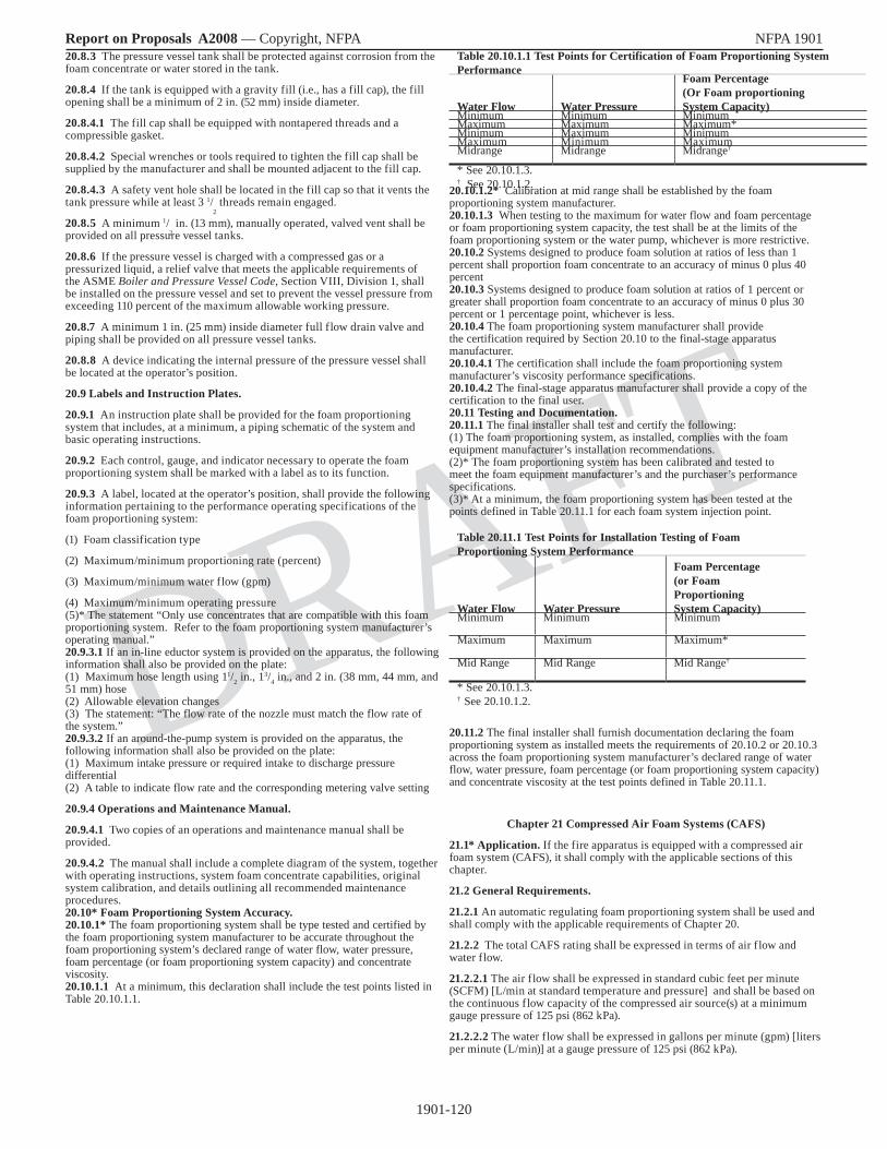
1901-120
Report on Proposals A2008 — Copyright, NFPA NFPA 1901
DRAFT
20.8.3 The pressure vessel tank shall be protected against corrosion from the foam concentrate or water stored in the tank.
20.8.4 If the tank is equipped with a gravity fill (i.e., has a fill cap), the fill opening shall be a minimum of 2 in. (52 mm) inside diameter.
20.8.4.1 The fill cap shall be equipped with nontapered threads and a compressible gasket.
20.8.4.2 Special wrenches or tools required to tighten the fill cap shall be supplied by the manufacturer and shall be mounted adjacent to the fill cap.
20.8.4.3 A safety vent hole shall be located in the fill cap so that it vents the tank pressure while at least 3 1/
2 threads remain engaged.
20.8.5 A minimum 1/2 in. (13 mm), manually operated, valved vent shall be
provided on all pressure vessel tanks.
20.8.6 If the pressure vessel is charged with a compressed gas or a pressurized liquid, a relief valve that meets the applicable requirements of the ASME Boiler and Pressure Vessel Code, Section VIII, Division 1, shall be installed on the pressure vessel and set to prevent the vessel pressure from exceeding 110 percent of the maximum allowable working pressure.
20.8.7 A minimum 1 in. (25 mm) inside diameter full flow drain valve and piping shall be provided on all pressure vessel tanks.
20.8.8 A device indicating the internal pressure of the pressure vessel shall be located at the operator’s position.
20.9 Labels and Instruction Plates.
20.9.1 An instruction plate shall be provided for the foam proportioning system that includes, at a minimum, a piping schematic of the system and basic operating instructions.
20.9.2 Each control, gauge, and indicator necessary to operate the foam proportioning system shall be marked with a label as to its function.
20.9.3 A label, located at the operator’s position, shall provide the following information pertaining to the performance operating specifications of the foam proportioning system:
(1) Foam classification type
(2) Maximum/minimum proportioning rate (percent)
(3) Maximum/minimum water flow (gpm)
(4) Maximum/minimum operating pressure(5)* The statement “Only use concentrates that are compatible with this foam proportioning system. Refer to the foam proportioning system manufacturer’s operating manual.”20.9.3.1 If an in-line eductor system is provided on the apparatus, the following information shall also be provided on the plate:(1) Maximum hose length using 11/2 in., 13/4 in., and 2 in. (38 mm, 44 mm, and 51 mm) hose(2) Allowable elevation changes(3) The statement: “The flow rate of the nozzle must match the flow rate of the system.”20.9.3.2 If an around-the-pump system is provided on the apparatus, the following information shall also be provided on the plate:(1) Maximum intake pressure or required intake to discharge pressure differential(2) A table to indicate flow rate and the corresponding metering valve setting
20.9.4 Operations and Maintenance Manual.
20.9.4.1 Two copies of an operations and maintenance manual shall be provided.
20.9.4.2 The manual shall include a complete diagram of the system, together with operating instructions, system foam concentrate capabilities, original system calibration, and details outlining all recommended maintenance procedures.20.10* Foam Proportioning System Accuracy.20.10.1* The foam proportioning system shall be type tested and certified by the foam proportioning system manufacturer to be accurate throughout the foam proportioning system’s declared range of water flow, water pressure, foam percentage (or foam proportioning system capacity) and concentrate viscosity.20.10.1.1 At a minimum, this declaration shall include the test points listed in Table 20.10.1.1.
Table 20.10.1.1 Test Points for Certification of Foam Proportioning System Performance
Water Flow Water Pressure
Foam Percentage (Or Foam proportioning System Capacity)
Minimum Minimum MinimumMaximum Maximum Maximum*Minimum Maximum MinimumMaximum Minimum MaximumMidrange Midrange Midrange†
* See 20.10.1.3.† See 20.10.1.2. 20.10.1.2* Calibration at mid range shall be established by the foam
proportioning system manufacturer.20.10.1.3 When testing to the maximum for water flow and foam percentage or foam proportioning system capacity, the test shall be at the limits of the foam proportioning system or the water pump, whichever is more restrictive.20.10.2 Systems designed to produce foam solution at ratios of less than 1 percent shall proportion foam concentrate to an accuracy of minus 0 plus 40 percent20.10.3 Systems designed to produce foam solution at ratios of 1 percent or greater shall proportion foam concentrate to an accuracy of minus 0 plus 30 percent or 1 percentage point, whichever is less.20.10.4 The foam proportioning system manufacturer shall provide the certification required by Section 20.10 to the final-stage apparatus manufacturer. 20.10.4.1 The certification shall include the foam proportioning system manufacturer’s viscosity performance specifications. 20.10.4.2 The final-stage apparatus manufacturer shall provide a copy of the certification to the final user. 20.11 Testing and Documentation.20.11.1 The final installer shall test and certify the following:(1) The foam proportioning system, as installed, complies with the foam equipment manufacturer’s installation recommendations.(2)* The foam proportioning system has been calibrated and tested to meet the foam equipment manufacturer’s and the purchaser’s performance specifications. (3)* At a minimum, the foam proportioning system has been tested at the points defined in Table 20.11.1 for each foam system injection point.
Table 20.11.1 Test Points for Installation Testing of Foam Proportioning System Performance
Water Flow Water Pressure
Foam Percentage (or Foam Proportioning System Capacity)
Minimum Minimum Minimum
Maximum Maximum Maximum*
Mid Range Mid Range Mid Range†
* See 20.10.1.3.† See 20.10.1.2.
20.11.2 The final installer shall furnish documentation declaring the foam proportioning system as installed meets the requirements of 20.10.2 or 20.10.3 across the foam proportioning system manufacturer’s declared range of water flow, water pressure, foam percentage (or foam proportioning system capacity) and concentrate viscosity at the test points defined in Table 20.11.1.
Chapter 21 Compressed Air Foam Systems (CAFS)
21.1* Application. If the fire apparatus is equipped with a compressed air foam system (CAFS), it shall comply with the applicable sections of this chapter.
21.2 General Requirements.
21.2.1 An automatic regulating foam proportioning system shall be used and shall comply with the applicable requirements of Chapter 20.
21.2.2 The total CAFS rating shall be expressed in terms of air flow and water flow.
21.2.2.1 The air flow shall be expressed in standard cubic feet per minute (SCFM) [L/min at standard temperature and pressure] and shall be based on the continuous flow capacity of the compressed air source(s) at a minimum gauge pressure of 125 psi (862 kPa).
21.2.2.2 The water flow shall be expressed in gallons per minute (gpm) [liters per minute (L/min)] at a gauge pressure of 125 psi (862 kPa).

1901-121
Report on Proposals A2008 — Copyright, NFPA NFPA 1901
DRAFT
21.2.3 The fire apparatus shall be capable of supplying power for operating the CAFS at its rated capacity while simultaneously providing power to all other power-dependent systems installed on the apparatus.21.2.4* On a CAFS, the air pressures shall be automatically balanced to the water pressure to within -0, +10 percent throughout the operational range of the CAFS.
21.2.5* A means shall be provided on the CAFS for the operator to relieve all pressure from the system after the system has been deactivated.
21.3 Compressed Air System.
21.3.1 The compressed air system operating in clean environmental conditions shall be designed to provide a continuous rated air supply for a duration of 6 hours without needing adjustment, additional lubrication, or air filters changed.
21.3.2 Relief Valve.
21.3.2.1 The compressed air system shall be equipped with a relief valve that is set to prevent the compressed air system from exceeding 110 percent of the maximum allowable working pressure of the system.
21.3.2.2 The outlet of the relief valve shall be routed to an area that does not expose personnel to air blasts or cause the creation of dust.
21.3.3 If the possibility exists for moisture to build up in the compressed air system, the system shall be equipped with moisture traps and drains.
21.3.4 If a holding, surge, or separator tank (DOT tank or ASME pressure vessel) is provided, it shall comply with 29 CFR 1910.169, “Air receivers,” or equal for the rated pressure.
21.3.4.1 Transportable air tanks shall comply with 49 CFR 178.37, “Specification 3AA and 3AAX, seamless steel cylinders,” or 29 CFR 1910.169, “Air receivers.”
21.3.4.2 Relief valves on transportable air tanks shall be of the ASME type on ASME cylinders and of the DOT type on DOT cylinders or equal for the rated pressure.
21.3.4.3 Valves installed on air tanks shall meet the requirements of the Compressed Gas Association or equivalent standards regarding pressure and usage with compressed air.
21.3.4.4 If the installation utilizes cylinders that require periodic testing, a label shall be placed on the operator’s panel indicating the test date stamped on the cylinders and the date the cylinders will next require testing.
21.4* Air Mixing.
21.4.1 An automatic means shall be provided to prevent the backflow of water or foam solution into the compressed air system, or air into the water pump or the foam proportioning equipment.
21.4.2 A means of mixing air and foam solution that provides for a homogeneous mixture of compressed air and foam solution shall be provided on CAFS.
21.5* Compressed Air System Piping. The discharge plumbing shall be configured to minimize the use of elbows or abrupt turns.
21.6 Air System Controls.
21.6.1 All compressed air system controls shall be located at the pump operator’s panel and shall be identified with an instruction plate in accordance with the requirements of 21.8.1.
21.6.2 Compressed air systems that require flushing after use shall be provided with controls that are accessible to the operator and enable the operator to completely flush the system with water according to the manufacturer’s instructions.
21.7 Foam System Pressure Gauges, Flowmeters, and Indicators.
21.7.1 The displays of all pressure gauges, flowmeters, and indicators (e.g., fluid level indicators) shall be located so they are visible from the pump operator’s position and shall meet the requirements of 4.10.3.
21.7.2 Where analog pressure gauges are used, they shall meet the requirements of 21.7.2.1 through 21.7.2.4.
21.7.2.1 Analog pressure gauges shall have a minimum accuracy of Grade B as defined in ASME B40.100, Pressure Gauges and Gauge Attachments.
21.7.2.2 Numerals for master gauges shall be a minimum of 5/32
in. (4 mm) high.
21.7.2.3 There shall be graduation lines showing at least every 10 psi (70 kPa), with major and intermediate graduation lines emphasized and figures at least every 100 psi (700 kPa).
21.7.2.4 Analog pressure gauges shall be vibration and pressure pulsation dampened; be resistant to corrosion, condensation, and shock; and have internal mechanisms that are factory lubricated for the life of the gauge.
21.7.3 If digital pressure gauges are used, they shall meet the requirements of 21.7.3.1 through 21.7.3.3.
21.7.3.1 The digits shall be at least 1/4 in. (6.4 mm) high.
21.7.3.2 Digital pressure gauges shall display pressure in increments of not more than 10 psi (70 kPa).
21.7.3.3 Digital pressure gauges shall have an accuracy of ±3 percent over the full scale.
21.7.4 Each pressure gauges and flowmeter, and its respective display, shall be mounted and attached so it is protected from accidental damage and excessive vibration.
21.7.5 If flowmeters are provided, they shall meet the requirements of 21.7.5.1 and 21.7.5.2.
21.7.5.1 Flowmeter displays shall be located at the pump operator’s panel and shall indicate the air flow in standard cubic feet per minute (SCFM) [L/min at standard temperature and pressure] and indicate the water flow in gallons per minute (gpm) [liters per minute (L/min)].
21.7.5.2 Flowmeters shall be rated to a hydrostatic burst gauge pressure of 500 psi (3400 kPa) if located on the pressure side of the system.
21.7.6* A pressure gauge shall be provided for the compressed air system.
21.8 Labels and Instruction Plates.
21.8.1 An instruction plate indicating the identification, function, and operation shall be provided for each control, gauge, and indicator required to operate the CAFS.
21.8.2 A label shall be provided that is visible from the pump operator’s position that gives the rated continuous flow capacity of the compressed air system at a gauge pressure of 125 psi (862 kPa).
21.8.3 An instruction plate shall be provided that is visible from the pump operator’s position that states the following:
(1) Open and close valves slowly.
(2) Do not run with just air/water.
(3) Shut off air when foam tank is empty.
(4) Be prepared for high nozzle reactions — open nozzle slowly.
21.8.4 Operations and Maintenance Manual.
21.8.4.1 Two copies of an operations and maintenance manual shall be provided.
21.8.4.2 The manual shall include a complete diagram of CAFS together with operating instructions, the system rating, and details outlining all recommended maintenance procedures.
21.9* Manufacturer’s Predelivery Tests. The manufacturer shall conduct the following tests prior to delivery of the fire apparatus and provide documentation of the test results to the purchaser at delivery of the fire apparatus.
21.9.1 CAFS Capacity Rating Test.
21.9.1.1 The operation of the water pump and the compressed air source shall be tested simultaneously to determine the integrity of the system and to ensure that the power available is capable of operating these components of CAFS simultaneously.
21.9.1.1.1 The compressed air system shall be operated at its flow capacity at a minimum gauge pressure of 125 psi (862 kPa), and the water pump shall discharge a minimum of 2 gpm (7.6 L/min) of water at 125 psi (862 kPa) net pump pressure for every 1 SCFM [28.3 L/min at standard temperature and pressure] of compressed air discharge.
21.9.1.1.2 The discharge shall be through at least two separate discharge openings, one discharging air only and the other discharging water only.
21.9.1.2 One or more lines of fire hose of sufficient diameter shall be provided to allow discharge of the required amount of water from the pump to a nozzle or other flow-measuring equipment without exceeding a flow velocity of 35 ft/sec (10.7 m/sec) [approximately 500 gpm (2000 L/min) for 2 ½ in. (65 mm) hose].
21.9.1.2.1 The discharge shall be measured using a smoothbore nozzle and pitot tube or other equipment such as flowmeters, volumetric tanks, or weigh tanks.

1901-122
Report on Proposals A2008 — Copyright, NFPA NFPA 1901
DRAFT
21.9.1.2.2 Test gauges shall meet the requirements of 16.13.2.2.4 and 16.13.2.2.5.
21.9.1.3 The airflow rate shall be measured using a pressure and temperature compensated flow-measuring device.
21.9.1.3.1 The airflow shall be measured in SCFM [L/min at standard temperature and pressure] at a minimum gauge pressure of 125 psi (862 kPa).
21.9.1.3.2 The airflow-measuring device shall have been calibrated for accuracy within the previous 3 months.
21.9.1.3.3* The air discharge outlet shall have nothing attached directly to it except the test device(s).
21.9.1.4 The water pump and the compressed air system shall be started and the rated flows and pressures as specified in 21.9.1.1.1 shall be established and maintained.
21.9.1.4.1 The system shall be run for 1 hour.
21.9.1.4.2 Readings of the airflow rate and pressure and the water pump pressure and discharge rate shall be taken at least every 10 minutes.
21.9.1.5 Failure of any component of the CAFS to maintain air and water pressures and discharge volumes at or above the system rating shall constitute failure of the test.
21.9.2 Standby Run Test.
21.9.2.1 One 200 ft (60 m) line of 1 ½ in. (38 mm) hose shall be connected to the discharge of the CAFS and shall be stretched out on level ground.
21.9.2.2 A quarter-turn valve of the same nominal size as the hose shall be installed at the discharge end.
21.9.2.3 The hose shall be restrained immediately behind the valve at the discharge end to prevent uncontrollable movement when the valve is opened.
21.9.2.4 Operating as a CAFS, with a gauge pressure air output at 125 psi (862 kPa), a foam flow shall be established in the hose line.
21.9.2.5 With the water tank at the half-full level, the valve at the discharge end of the hose shall be shut no faster than in 3 seconds and no slower than in 10 seconds.
21.9.2.6 The engine(s) speed shall be maintained for 10 minutes without discharging water, air, or foam solution from the CAFS and without operator intervention.
21.9.2.7 A bypass line shall be permitted to be opened temporarily, if needed, to keep the water temperature in the pump within acceptable limits.
21.9.2.8 At the end of 10 minutes, the valve shall be reopened no faster than in 3 seconds and no slower than in 10 seconds.
21.9.2.9 Either damage to the CAFS that affects its rated performance characteristics or the lack of a fire stream immediately upon opening the hose line shall constitute failure of this test.
Chapter 22 Line Voltage Electrical Systems
22.1* Application. Where any part of a line voltage electrical system is provided as a fixed installation, the applicable requirements of this chapter shall apply.
22.2 General Requirements.
22.2.1 Stability.
22.2.1.1 Any fixed line voltage power source producing alternating current (ac) shall produce electric power at 60 Hz ±3 Hz when producing power at all levels between no load and full rated power.
22.2.1.2 Any fixed line voltage power source shall produce electric power at the rated voltage ± 5percent when producing power at all levels between no load and full rated power.
22.2.2 The maximum voltage supplied to portable equipment shall not exceed 275 volts to ground. Higher voltage shall be permitted only when used to operate fixed wired, permanently mounted equipment on the apparatus.
22.2.3 Conformance with National Electrical Code®.
22.2.3.1 All components, equipment, and installation procedures shall conform to NFPA 70, National Electrical Code, except where superseded by the requirements of this chapter.
22.2.3.2 Where the requirements of this chapter differ from those in the NFPA 70, National Electrical Code, the requirements in this chapter shall apply.
22.2.4* When available, line voltage electrical system equipment and materials included on the apparatus shall be listed and used only in the manner for which they have been listed.
22.2.5 All equipment and materials shall be installed in accordance with the manufacturer’s instructions.
22.2.6 Location Ratings.
22.2.6.1 Any equipment used in a dry location shall be listed for dry locations.
22.2.6.2 Any equipment used in a wet location shall be listed for wet locations.
22.2.6.3 Any equipment, except a power takeoff driven generator, used in an underbody or underchassis location that is subject to road spray shall be either listed as Type 4 or mounted in an enclosure that is listed as Type 4.
22.2.6.4* If a power takeoff driven generator is located in an underbody or underchassis location, the installation shall include a shield to prevent road spray from splashing directly on the generator.
22.3 Grounding and Bonding.
22.3.1* Grounding. Grounding shall be in accordance with Section 250.34(A) and 250.34(B) of NFPA 70, National Electrical Code.
22.3.1.1* Ungrounded systems shall not be used.
22.3.1.2 Only stranded or braided copper conductors shall be used for grounding and bonding.
22.3.1.3 Any bonding screws, straps, or buses in the distribution panelboard or in other system components between the neutral and equipment-grounding conductor shall be removed and discarded.
22.3.2 Bonding.
22.3.2.1* No current carrying conductor shall be connected to the generator frame, vehicle frame, or vehicle body.
22.3.2.2* If a connection between one of the current carrying conductors (neutral) and the power source frame, case, or the protective ground wire is made within the power source and can not be broken or if the fire apparatus line voltage electrical system is intended to serve as an emergency generator for a building electrical system, a grounded neutral system shall be permitted.
22.3.2.2.1 In this case, the neutral conductor of the power source shall be bonded to the vehicle frame.
22.3.2.2.2 The neutral bonding connection shall occur only at the power source.
22.3.2.2.3 If the neutral must be bonded to the frame, the power source specification label shall include the following statement: “Warning: One current carrying conductor of this line voltage electrical system is connected to the vehicle frame and body.”
22.3.2.3 In addition to the bonding required for the low voltage return current, each body and each driving or crew compartment enclosure shall be bonded to the vehicle frame by a copper conductor.
22.3.2.3.1 The conductor shall have a minimum amperage rating, as defined in Section 310.15, “Ampacities for Conductors Rated 0–2000 Volts,” of NFPA 70, of 115 percent of the rated amperage on the power source specification label.
22.3.2.3.2 A single conductor that is sized to meet the low voltage and line voltage requirements shall be permitted to be used.22.3.3* Ground Fault Circuit Interrupters. 22.3.3.1 Ground fault circuit interrupters (GFCIs), either integrated into outlets, integrated into circuit breakers, or as stand alone devices, shall be permitted to be used but are not required other than in the situations described in 22.3.3.2.
22.3.3.2 In special service vehicles incorporating a lavatory, sink, toilet, shower, or tub; 120 volt, 15- or 20-ampere receptacles within 6 feet (1.8 meters) of these fixtures shall have ground fault circuit interrupter protection if they can be powered from an external source (shoreline) or if the neutral is bonded to the vehicle frame.
22.4 Power Source General Requirements. The following requirements shall apply to all line voltage power sources.
22.4.1 All power source system mechanical and electrical components shall be sized to support the continuous duty nameplate rating of the power source.
22.4.2 The power source shall be shielded from contamination that will prevent the power source from operating within its design specifications.
22.4.3* Power Source Rating.
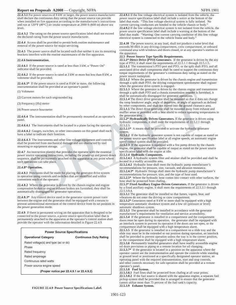
1901-123
Report on Proposals A2008 — Copyright, NFPA NFPA 1901
DRAFT
22.4.3.1 For power sources of 8 kW or larger, the power source manufacturer shall declare the continuous duty rating that the power source can provide when installed on fire apparatus according to the manufacturer’s instructions and run at 120°F (49°C) air intake temperature at 2000 ft (600 m) above sea level.
22.4.3.2 The rating on the power source specification label shall not exceed the declared rating from the power source manufacturer.
22.4.4 Access shall be provided to permit both routine maintenance and removal of the power source for major servicing.
22.4.5 The power source shall be located such that neither it nor its mounting brackets interfere with the routine maintenance of the fire apparatus.
22.4.6 Instrumentation.
22.4.6.1 If the power source is rated at less than 3 kW, a “Power On” indicator shall be provided.
22.4.6.2 If the power source is rated at 3 kW or more but less than 8 kW, a voltmeter shall be provided.
22.4.6.3* If the power source is rated at 8 kW or more, the following instrumentation shall be provided at an operator’s panel: (1) Voltmeter
(2) Current meters for each ungrounded leg
(3) Frequency (Hz) meter
(4) Power source hourmeter
22.4.6.4 The instrumentation shall be permanently mounted at an operator’s panel.
22.4.6.4.1 The instruments shall be located in a plane facing the operator.
22.4.6.4.2 Gauges, switches, or other instruments on this panel shall each have a label to indicate their function.
22.4.6.4.3 The instruments and other line voltage equipment and controls shall be protected from mechanical damage and not obstructed by tool mounting or equipment storage.
22.4.7 An instruction plate(s) that provides the operator with the essential power source operating instructions, including the power-up and power-down sequence, shall be permanently attached to the apparatus at any point where such operations can take place.
22.4.8* Operation.
22.4.8.1 Provisions shall be made for placing the generator drive system in operation using controls and switches that are identified and within convenient reach of the operator.
22.4.8.2 Where the generator is driven by the chassis engine and engine compression brakes or engine exhaust brakes are furnished, they shall be automatically disengaged for generator operations.
22.4.8.3* Any control device used in the generator system power train between the engine and the generator shall be equipped with a means to prevent unintentional movement of the control device from its set position in the power generation mode.
22.4.9 If there is permanent wiring on the apparatus that is designed to be connected to the power source, a power source specification label that is permanently attached to the apparatus at the operator’s control station shall provide the operator with the information detailed in Figure 22.4.9.
FIGURE 22.4.9 Power Source Specifications Label.
22.4.9.1 If the line voltage electrical system is isolated from the vehicle, the power source specification label shall include a notice at the bottom of the label that reads: “This line voltage electrical system is fully isolated. No current carrying conductors are bonded to the vehicle chassis or body.”22.4.9.2 If the line voltage electrical system is not isolated from the vehicle, the power source specification label shall include a warning at the bottom of the label that reads: “Warning: One current carrying conductor of this line voltage electrical system is connected to the vehicle frame and body.”
22.4.10 The power source, at any load, shall not produce a noise level that exceeds 90 dBA in any driving compartment, crew compartment, or onboard command area with windows and doors closed, or at any operator’s station on the apparatus.22.5 Power Source Type Specific Requirements. 22.5.1* Direct Drive (PTO) Generators. If the generator is driven by the any type of PTO, it shall meet the requirements of 22.5.1.1 through 22.5.1.5.22.5.1.1 The transmission’s PTO port and PTO, or the split shaft PTO, and all associated drive shaft components shall be rated to support the continuous duty torque requirements of the generator’s continuous duty rating as stated on the power source nameplate.22.5.1.2 Where the generator is driven by the chassis engine and transmission through a split shaft PTO, the driving compartment speedometer shall register when the generator drive system is engaged.22.5.1.3 Where the generator is driven by the chassis engine and transmission through a split shaft PTO and a chassis transmission retarder is furnished, it shall be automatically disengaged for generator operations.22.5.1.4 The direct drive generator shall be mounted so that it does not change the ramp breakover angle, angle of departure, or angle of approach as defined by other components, and shall not extend into the ground clearance area.22.5.1.5 The direct drive generator shall be mounted away from exhaust and muffler areas or provided with a heat shield to reduce operating temperatures in the generator area.22.5.2* Hydraulically Driven Generators. If the generator is driven using hydraulic components, it shall meet the requirements of 22.5.2.1 through 22.5.2.5.22.5.2.1* A means shall be provided to activate the hydraulic generator system.22.5.2.2 If the hydraulic generator system is not capable of output as stated on the power source specification label at all engine speeds, an automatic engine speed control system shall be provided.22.5.2.3 If the apparatus is equipped with a fire pump driven by the chassis engine, the generator shall be capable of output as stated on the power source specification label with the engine at idle.22.5.2.4 Hydraulic Components.22.5.2.4.1 A hydraulic system filter and strainer shall be provided and shall be located in a readily accessible area.22.5.2.4.2 Hydraulic hose shall meet the hydraulic pump manufacturer’s recommendations for pressure, size, vacuum, and abrasion resistance.22.5.2.4.3* Hydraulic fittings shall meet the hydraulic pump manufacturer’s recommendations for pressure, size, and the type of hose used.22.5.2.5* Where the hydraulic hose comes into contact with other surfaces, the hose shall be protected from chafing.22.5.3* Fixed Auxiliary Engine-Driven Generators. If the generator is driven by a fixed auxiliary engine, it shall meet the requirements of 22.5.3.1 through 22.5.3.9.4.22.5.3.1 The generator shall be installed so that fumes, vapors, heat, and vibrations do not enter the driving or crew compartment.22.5.3.2* Generators rated at 8 kW or more shall be equipped with a high temperature automatic shutdown system and a low oil (pressure or level) automatic shutdown system.22.5.3.3 The generator shall be installed in accordance with the generator manufacturer’s requirements for ventilation and service accessibility.22.5.3.4 If the generator is installed in a compartment and the compartment doors must be open during its operation, the generator shall be equipped with an interlock system to prevent its operation if the doors are not open, or the compartment shall be equipped with a high temperature alarm.22.5.3.5 If the generator is installed in a compartment on a slide tray and the slide tray must be in the extended or out position during operation, an interlock shall be provided to prevent operation unless the tray is in the correct position, or the compartment shall be equipped with a high temperature alarm.22.5.3.6 Permanently installed generators shall have readily accessible engine oil drain provisions or piping to a remote location for oil changing.22.5.3.7* If the generator is located in a position on the apparatus where the operator cannot see the instrumentation and operate the controls while standing at ground level or positioned at a specifically designated operator station, an operating panel with the required instrumentation, start and stop controls, and other controls necessary for safe operation shall be provided at a remote operator’s panel.22.5.3.8 Fuel System.22.5.3.8.1 Fuel lines shall be protected from chafing at all wear points.22.5.3.8.2 If the fuel source is shared with the apparatus engine, a separate fuel pickup system shall be provided that is arranged to ensure that the generator cannot utilize more than 75 percent of the fuel tank’s capacity.22.5.3.9 Exhaust System.
Power Source Specifications
Operational Category
Rated voltage(s) and type (ac or dc)PhaseRated frequencyRated amperageContinuous rated wattsPower source engine speed
Continuous Duty Rating
(Proper notice per 22.4.9.1 or 22.4.9.2)

1901-124
Report on Proposals A2008 — Copyright, NFPA NFPA 1901
DRAFT
22.5.3.9.1* The exhaust piping and discharge shall be located or shielded to prevent thermal damage to the apparatus or equipment.22.5.3.9.2 The exhaust shall be piped to the exterior of the vehicle and discharged at a location away from any operator’s position.22.5.3.9.3 Where parts of the exhaust system are exposed so that they can cause injury to operating personnel, protective guards shall be provided.22.5.3.9.4 Silencing devices shall be provided and shall not create exhaust backpressure that exceeds the limits specified by the engine manufacturer.22.5.4* Belt Driven Power Sources. If the power source is belt driven, it shall meet the requirements of 22.5.4.1 through 22.5.4.3.22.5.4.1 A means shall be provided to mechanically engage and disengage the generator or alternator rotation, or to electronically stop the production of electricity from the generator or alternator.22.5.4.2 A voltmeter shall be provided at an operator’s panel for any system of this type.22.5.4.3 The belt drive system shall be rated to drive the generator or alternator at the nameplate rating.22.5.5* Line Voltage Power Derived from the Apparatus Low Voltage Power Supply Systems. If the power source derives its input energy from the apparatus low voltage electrical system, it shall meet the requirements of 22.5.5.1 and 22.5.5.2.22.5.5.1 The low voltage power supply system shall be installed in compliance with the requirements of Chapter 13.22.5.5.2* The alternator and/or battery system shall be adequate to provide power for continuous operation for a minimum of 2 hours at full output.22.5.6 Power Sources Requiring Elevated Engine Speed. If the power source requires the chassis engine to be operating at a specific fixed speed or a specific speed range, it shall meet the requirements of 22.5.6.1 through 22.5.6.3.22.5.6.1 The main propulsion engine shall have a governor capable of maintaining the engine speed within the limits required by the power source to meet the frequency control, voltage control, and power output specifications. 22.5.6.2 An interlock shall prevent engagement of the generator unless the parking brake is engaged and the transmission is in neutral or not connected to the drive wheels. 22.5.6.3* Where the chassis engine drives the generator and electronic engine throttle controls are provided, an interlock shall prevent engine speed control from any other source that would interfere with the generator while the generator is operating.22.5.7 Power Sources Requiring the Chassis Transmission to be in a Specific Gear. If the power source requires the chassis transmission be in a specific gear when producing line voltage power, it shall meet the requirements of 22.5.7.1 and 22.5.7.2.22.5.7.1 A label indicating the chassis transmission shift selector position to be used for generator operation shall be provided in the driving compartment and located so that it can be read from the driver’s position.22.5.7.2 Interlocks shall be provided that prevent advancement of the engine throttle for generator operation unless the transmission is in the correct gear.22.5.8 Generators. If the power source is mechanically driven, it shall comply with Article 445, “Generators” of NFPA 70, National Electrical Code.22.5.9 Chassis Engine-Driven Generators. Where the generator is driven by the chassis engine, the requirements in 22.5.9.1 through 22.5.9.3 shall apply.22.5.9.1* Unless the generator is always engaged, a “Generator Engaged” indicator shall be provided in the driving compartment to indicate that the generator shift has been successfully completed.22.5.9.2 Unless the generator is always engaged and operating, an “OK to Operate Generator” indicator shall be provided in the driving compartment to indicate that the generator is engaged (if not always engaged), the transmission is in the proper gear (if required, automatic transmissions only), and the parking brake is engaged (if applicable).22.5.9.3 An interlock system shall be provided to prevent advancement of the engine speed in the driving compartment or at any operator’s panel unless the parking brake is engaged, and the transmission is in neutral or the output of the transmission is correctly connected to a pump or generator instead of the drive wheels.22.5.10* Waveform Created Electronically. If the power output waveform is electronically created, the purchaser shall specify whether modified sine wave or pure sine wave output is required.
22.6* Portable Generator Installations. The generator shall comply with Article 445, “Generators,” of NFPA 70, National Electrical Code.
22.6.1 Any portable generator that can be operated while mounted on the apparatus shall be as follows: (1) Installed so that fumes, vapors, heat, excessive noise, and vibrations do not enter interior driving or crew compartments or damage the generator during operation
(2) Have the exhaust outlet located so that exhaust is directed away from any operator station located on the apparatus and guarded to protect the operator
22.6.2 If the portable generator is remotely mounted, it shall have a remote operator’s control station that shall provide a means for starting and stopping the generator and monitoring the same instrumentation as is required for fixed power sources.
22.6.3 Wiring for Portable Generator Installations. Wiring installed for the purpose of facilitating the distribution of power from a portable generator installation to fixed wiring on the apparatus shall conform to the additional requirements of 22.6.3.1 through 22.6.3.5.
22.6.3.1 Circuit conductors shall be sized in relation to the power source specification label rating and shall be protected by an overcurrent device commensurate with their amperage capacities.
22.6.3.2 There shall be a single output connector cord with all of the conductors in the cord sized to carry a minimum of 115 percent of the nameplate amperage.
22.6.3.3 If there is not an overcurrent protection device at the power source, the output connector cord shall not exceed 72 in. (1830 mm) in length and shall be connected to an overcurrent protection device.
22.6.3.4 The rating of an external main overcurrent protection device shall equal the rated amperage on the power source specification label or the next larger available size overcurrent protection device where so recommended by the power source manufacturer.
22.6.3.5 If a connecting plug is required, it shall be sized in relation to the system and conform to NEMA configurations for plugs.
22.7 Line Voltage Supplied from an External Source.
22.7.1* If the apparatus is equipped with a fixed power inlet (shoreline inlet), it shall be a permanently mounted inlet (male-recessed type with cover), sized in accordance with the anticipated load, and wired directly to the system or device to be powered or wired to a transfer switch where required by 22.7.2.
22.7.1.1 The protective ground from the shoreline inlet shall be bonded to the vehicle frame.
22.7.1.2 The neutral conductor from the shoreline inlet shall be bonded to the vehicle frame.
22.7.2 Transfer Switch Applications.
22.7.2.1 A transfer switch shall be required to isolate one power source from the other where a circuit(s) is intended to be supplied from more than one power source.
22.7.2.2Transfer equipment, including transfer switches, shall operate such that all conductors of one power source are disconnected before any conductors of the second power source are connected.
22.7.2.3 If the power source is isolated from the vehicle frame and body, the neutral conductor shall be switched through the transfer switch to maintain the isolation.
22.7.3 The apparatus shall have a label permanently affixed at the power inlet that indicates the information shown in Figure 22.7.3.
FIGURE 22.7.3 Power Inlet Label.[Existing Figure 23.8.3, 2003 ed., (no change)]
22.8 Power Supply Assembly.
22.8.1 The conductors used in the power supply assembly between the output terminals of the power source and the main overcurrent protection device shall not exceed 12 ft (4 m) in length.
22.8.2 All power supply assembly conductors, including neutral and grounding conductors, shall have an equivalent amperage rating and shall be sized to carry not less than 115 percent of the amperage of the nameplate current rating of the power source.
22.8.3* If the power supply assembly connects to the vibrating part of a generator (not a connection on the base) the conductors shall be flexible cord or other fine-stranded conductors enclosed in metallic or nonmetallic liquidtight flexible conduit, rated for wet locations and temperatures not less than 194°F (90°C).
22.9 Overcurrent Protection. Manually resettable overcurrent devices shall be installed to protect the line voltage electrical system components.
22.9.1 Power Source Protection. A main overcurrent protection device shall be provided that is either incorporated in the power source or connected to the power source by a power supply assembly.
22.9.1.1 The size of the main overcurrent protection device shall not exceed 100 percent of the rated amperage stated on the power source specification label or the rating of the next larger available size overcurrent protection device, where so recommended by the power source manufacturer.
22.9.1.2 If the main overcurrent protection device is subject to road spray, the unit shall be housed in a Type 4 rated enclosure.

1901-125
Report on Proposals A2008 — Copyright, NFPA NFPA 1901
DRAFT
22.9.2 Branch Circuit Overcurrent Protection. Overcurrent protection devices shall be provided for each individual circuit and shall be sized at not less than 15 amps in accordance with Section 240.4, “Protection of Conductors,” of NFPA 70, National Electrical Code.
22.9.2.1 Any panelboard shall have a main breaker where the panel has six or more individual branch circuits or the power source is rated 8 kW or larger.
22.9.2.2 Each overcurrent protection device shall be marked with a label to identify the function of the circuit it protects.
22.9.2.3 Dedicated circuits shall be provided for any large appliance or device (air conditioning units, large motors, etc.) that requires 60 percent or more of the rated capacity of the circuit to which it is connected, and that circuit shall serve no other purpose.
22.9.3 Panelboards. All fixed power sources shall be hardwired to a permanently mounted panelboard unless one of the following exist:
(1) All line voltage power connections are made through receptacles on the power source and the receptacles are protected by integrated overcurrent devices
(2) Only one circuit is hardwired to the power source, which is protected by an integrated overcurrent device
22.9.3.1 The panel shall be visible and located so that there is unimpeded access to the panelboard controls.
22.9.3.2 All panelboards shall be designed for use in their intended location.
22.9.3.3 The panel(s) shall be protected from mechanical damage, tool mounting, and equipment storage.22.9.3.4* Where the power source is 120/240 volts and 120 volt loads are connected, the apparatus manufacturer or line voltage system installer shall consider load balancing to the extent that it is possible.
22.10* Wiring Methods. Fixed wiring systems shall be limited to the following:
(1) Metallic or nonmetallic liquidtight flexible conduit rated at temperatures not less than 194°F (90°C) with stranded copper wire rated for wet locations and temperatures not less than 194°F (90°C)
(2) Type SOW, SOOW, SEOW, or SEOOW flexible cord, rated at 600 volts and at temperatures not less than 194°F (90°C)
22.10.1 Electrical cord or conduit shall not be attached to chassis suspension components, water or fuel lines, air or air brake lines, fire pump piping, hydraulic lines, exhaust system components, or low voltage wiring and shall be arranged as follows:
(1) Separated by a minimum distance of 12 in. (300 mm) from exhaust piping or shielded from such piping
(2) Separated from fuel lines by a minimum distance of 6 in. (150 mm)
22.10.2 A means shall be provided to allow “flexing” between the driving and crew compartment, the body, and other areas or equipment whose movement would stress the wiring.
22.10.3 Electrical cord or conduit shall be supported within 6 in. (150 mm) of any junction box and at a minimum of every 24 in. (600 mm) of run.
22.10.3.1 Supports shall be made of nonmetallic materials, or corrosion-resistant or corrosion-protected metal.
22.10.3.2 All supports shall be of a design that does not cut or abrade the conduit or cord and shall be mechanically fastened to the apparatus.
22.10.4 Only fittings and components listed for the type of cord or conduit being installed shall be used.
22.10.5 Splices shall be made only in a listed junction box.
22.10.6 Additional Requirements for Flexible Cord Installations.
22.10.6.1* Where flexible cord is used in any location where it could be damaged, it shall be protected by installation in conduit, enclosures, or guards.
22.10.6.2 Where flexible cord penetrates a metal surface, rubber or plastic grommets or bushings shall be installed.
22.10.7 Wiring Identification.
22.10.7.1 Each line voltage circuit originating from the main panelboard shall be identified.
22.10.7.2 The wire or circuit identification either shall reference a wiring diagram or wire list or shall indicate the final termination point of the circuit.
22.10.7.3 Where prewiring for future power sources or devices exists, the unterminated ends shall be marked with a label showing their wire size and intended function.
22.11 Wiring System Components.
22.11.1 Only stranded copper conductors with an insulation rated for temperatures of at least 194°F (90°C) and wet locations shall be used.
22.11.1.1 Conductors in flexible cord shall be sized in accordance with Table 400.5(A) of NFPA 70, National Electrical Code.
22.11.1.2 Conductors used in conduit shall be sized in accordance with Section 310.15, “Ampacities for Conductors Rated 0-2000 Volts,” of NFPA 70.
22.11.1.3 Aluminum or copper-clad aluminum conductors shall not be used.
22.11.2 All boxes shall conform to and be mounted in accordance with Article 314, “Outlet, Device, Pull, and Junction Boxes; Conduit Bodies; Fittings; and Manholes,” of NFPA 70.
22.11.2.1 All boxes shall be accessible using ordinary hand tools.
22.11.2.2 Boxes shall not be permitted behind welded or pop-riveted panels.
22.11.2.3 The maximum number of conductors permitted in any box shall be in accordance with Section 314.16, “Number of Conductors in Outlet, Device, and Junction Boxes, and Conduit Bodies,” of NFPA 70.
22.11.3* All wiring connections and terminations shall provide a positive mechanical and electrical connection.
22.11.3.1 Connectors shall be installed in accordance with the manufacturer’s instructions.
22.11.3.2 Wire nuts or insulation displacement and insulation-piercing connectors shall not be used.
22.11.4* Each switch shall indicate the position of its contact points (i.e., open or closed) and shall be rated for the continuous operation of the load being controlled.
22.11.4.1 All switches shall be marked with a label indicating the function of the switch.
22.11.4.2* Circuit breakers used as switches shall be “switch rated” (SWD) or better.
22.11.4.3 Switches shall simultaneously open all associated line voltage conductors.
22.11.4.4 Switching of the neutral conductor alone shall not be permitted.
22.11.4.5 Line voltage circuits controlled by low voltage circuits shall be wired through properly rated relays in listed enclosures that control all nongrounded current-carrying conductors.
22.11.5 Receptacles and Inlet Devices.
22.11.5.1 Wet and Dry Locations.
22.11.5.1.1* All wet location receptacle outlets and inlet devices including those on hardwired, remote power distribution boxes, shall be of the grounding type, provided with a wet location cover, and installed in accordance with Section 406.8, “Receptacles in Damp or Wet Locations,” of NFPA 70, National Electrical Code.
22.11.5.1.2 All receptacles located in a wet location shall be not less than 24 in. (600 mm) from the ground.
22.11.5.1.3* Receptacles on offroad fire apparatus shall be a minimum of 30 in. (750 mm) from the ground.
22.11.5.2 All receptacles located in a dry location shall be of the grounding type and shall be at least 12 in. (300 mm) above the interior floor height.
22.11.5.3 No receptacle shall be installed in a face-up position.
22.11.5.4 The face of any wet location receptacle shall be installed in a plane from vertical to not more than 45 degrees off vertical.
22.11.5.5 Receptacle Label.
22.11.5.5.1 Each receptacle shall be marked with a label indicating the nominal line voltage (120 volts or 240 volts) and the current rating in amps of the circuit.
22.11.5.5.2 If the receptacle is dc or other than single phase, that information shall also be marked on the label.
22.11.5.6* All receptacles and electrical inlet devices shall be listed to UL 498, Standard for Safety Attachment Plugs and Receptacles, or other recognized performance standards.

1901-126
Report on Proposals A2008 — Copyright, NFPA NFPA 1901
DRAFT
22.11.5.7 Receptacles used for dc voltages shall be rated for dc service.
22.12 Cord Reels. All permanently mounted cord reels shall be rated for continuous duty and installed to be accessible for removal, cord access, maintenance, and servicing.
22.12.1 The power rewind cord reel spool area shall be visible to the operator during the rewind operation, or the reel spool shall be encapsulated to prevent cord from spooling off the reel.
22.12.2 Rollers or guides shall be provided, where required, to prevent damage to the cord at reel spools or compartment openings.
22.12.3 Rewind Provision.
22.12.3.1 Manually operated reels shall have a hand crank.
22.12.3.2 Power rewind–type reels shall have the control in a position where the operator can observe the rewinding operation. If a reel is in an enclosure or out of direct view, the cord entry point to the enclosure shall be visible to the operator of the reel control.
22.12.3.3 The rewind control or crank shall not be over 72 in. (1830 mm) above the operator’s standing position.
22.12.3.4 The rewind control shall be marked with a label indicating its function and shall be guarded to prevent accidental operation.
22.12.4* The reel shall be designed to hold 110 percent of the capacity needed for the intended cord length.
22.12.5* The wire size shall be in accordance with NFPA 70, National Electrical Code, Table 400.5(A), but in no case shall it be smaller than 12 AWG.
22.12.6* Electrical cord shall be Type SEOOW, Type SOOW, or Type STOOW.
22.12.7* A label that indicates the following information shall be provided in a visible location adjacent to any permanently connected reel. (1) Current rating
(2) Current type
(3) Phase
(4) Voltage
(5) Total cord length
22.12.8 Where a power distribution box is hardwired to the end of a cord that is stored on a fixed cord reel or other fixed storage means, the requirements in 22.12.8.1 through 22.12.8.6 shall apply.
22.12.8.1 The remote power distribution box shall be listed for use in a wet location.
22.12.8.2* The distribution box shall be as follows: (1) Protected from corrosion
(2) Capable of being carried with a gloved hand
(3) Designed to keep the exterior electrical components above 2 in. (51 mm) of standing water
22.12.8.3* Inlets, receptacles, circuit breakers, or GFCI devices shall not be mounted on the top surface of the horizontal plane.
22.12.8.4 Branch circuit breakers shall be installed in the remote power distribution box if the overcurrent device protecting the feed cord to the box is too large to protect the wiring supplying the devices plugged onto the distribution box.
22.12.8.5* Remote power distribution boxes shall have a light on the box to indicate the power is on.
22.12.8.5.1* The light shall be visible in a 360 degree plane from a minimum of 200 ft (60 m) in complete darkness.
22.12.8.5.2 The light shall be mechanically protected to prevent damage.
22.12.8.6 The hardwired portable cord connection to the box shall have strain relief and meet the intended usage requirements.
22.13 Scene Lighting Systems. Where fixed scene lights are supplied, the requirements in 22.13.1 through 22.13.4 shall apply.
22.13.1 All scene lights shall be provided with a lens or a means for preventing damage from water spray and shall be listed for wet location usage.
22.13.2 Handle on Lights.
22.13.2.1 If the light is adjustable, a handle shall be provided.22.13.2.2 The design of the light shall not allow the temperature of the handle to exceed 131°F (55°C).22.13.3 The manufacturer of the device shall have the scene light tested by a nationally recognized testing laboratory and listed to UL 153 Standard for Portable Electric Luminaires or UL 1598, Luminaires. 22.13.4 If manually operated floodlights are not operable from the ground, access steps that meet the requirements of Section 15.7 and handrails that meet the requirements of Section 15.8 shall be provided to allow the user to reach the floodlights.
22.14 Power-Operated Light Mast.
22.14.1* General.
22.14.1.1 The mast shall be designed to sustain the intended tip load with at least a 125 percent safety factor.
22.14.1.2 The mast shall withstand a minimum of a 50 mph (80 kph) wind in a raised, unguyed position.
22.14.2* Installation and Operational Requirements.
22.14.2.1 The mast shall be capable of being raised within 2 minutes.
22.14.2.2 Where the installation precludes the operator from seeing the light in its nested position, a means shall be provided to allow the operator to align the light for nesting when the operator is at the operator’s position.
22.14.2.3* Appropriate warning labels on the hazards of electrocution shall be installed.
22.14.2.4 A means shall be provided to prevent operations that could cause damage to the power supply conductors.
22.14.2.5 In the event of a failure of the light tower’s raising system while the tower is deployed or being deployed, a means shall be provided to limit the rate of descent in order to prevent injury to equipment or personnel.
22.14.2.6 A secondary means of control shall be provided to allow for emergency lowering of the mast.
22.14.2.7 Where the tower is powered by the chassis air brake system, the air supply shall be from an auxiliary air circuit that is equipped with a pressure protection valve and an auxiliary air tank(s).
22.14.2.8* An automatic deenergizing means shall be provided so there is no electrical power to the mast or to the light wiring when the mast is in a stowed position.
22.14.2.9 The hazard warning light required in Section 13.11 shall be illuminated whenever the light tower is not in the stowed position.
22.14.2.10 The operational envelope of the mast shall be automatically illuminated whenever the mast assembly is being raised, lowered, or rotated.
22.14.3 Labeling.
22.14.3.1 An instruction plate showing the operation of the mast and operational warning signs shall be provided at the operator’s position.
22.14.3.2 A label shall be provided at the operator’s position to indicate the following: (1) Extended tower height from the ground
(2) Bulb replacement data
22.15* Electrical System Testing.
22.15.1 The wiring and associated equipment shall be tested by the apparatus manufacturer or the installer of the line voltage system.
22.15.2 Dielectric Voltage Withstand Test.
22.15.2.1 The wiring and permanently connected devices and equipment shall be subjected to a dielectric voltage withstand test of 900 volts for 1 minute.
22.15.2.2 The testing shall be performed after all body work has been completed.
22.15.2.3* The test shall be conducted as follows: (1) Isolate the power source from the panel board and disconnect any solid state low voltage components.
(2) Connect one lead of the dielectric tester to all the hot and neutral busses tied together.
(3) Connect the other lead to the fire apparatus frame or body.

1901-127
Report on Proposals A2008 — Copyright, NFPA NFPA 1901
DRAFT
(4) Close any switches and circuit breakers in the circuit(s).
(5) Apply the dielectric voltage for 1 minute in accordance with the testing equipment manufacturer’s instructions.
22.15.3* The electrical polarity of all permanently wired equipment, cord reels, and receptacles shall be tested to verify that wiring connections have been properly made.22.15.4 Electrical continuity shall be verified from the chassis or body to all line voltage electrical enclosures, light housings, motor housings, light poles, switch boxes, and receptacle ground connections that are accessible to the firefighter in normal operations.22.15.5 If the apparatus is equipped with a transfer switch, it shall be tested to verify operation and that all non-grounded conductors are switched.
22.15.6 Electrical light towers, floodlights, motors, fixed appliances, and portable generators shall be operated at their full rating or capacity for 30 minutes to ensure proper operation.22.15.7* Certification Test of Power Source22.15.7.1 The apparatus manufacturer or installer of the power source shall perform a certification test on the power source.
22.15.7.2 The testing of the power source shall be witnessed, and the results of the tests of the power source shall be certified by an independent third-party certification organization.
22.15.7.3 Test Procedure.
22.15.7.3.1 The prime mover shall be started from a cold start condition and the unloaded voltage and frequency shall be recorded.
22.15.7.3.2 The line voltage electrical system shall be loaded to at least 100 percent of the continuous rated wattage stated on the power source specification label. Testing with a resistive load bank shall be permitted.
22.15.7.3.3 The power source shall be operated in the manner specified by the apparatus manufacturer as documented on instruction plates or in operation manuals.
22.15.7.3.4 The power source shall be operated at a minimum of 100 percent of the continuous rated wattage as stated on the power source specification label for a minimum of 2 hours.
22.15.7.3.4.1 The load shall be adjusted to maintain the output wattage at or above the continuous rated wattage during the entire 2 hour test.
22.15.7.3.4.2 The following conditions shall be recorded at least every ½ hour during the test. (1) The power source output voltage, frequency, and amperes
(2) The prime mover’s oil pressure, water temperature, and transmission temperature, if applicable
(3) The power source hydraulic fluid temperature, if applicable
(4) The ambient temperature and power source air inlet temperature
22.15.7.3.4.3 The following conditions shall be recorded once during the test for power sources driven by dedicated auxiliary internal combustion engines. (1) Altitude
(2) Barometric pressure
(3) Relative humidity 22.15.7.3.5 If the generator is driven by the chassis engine and the generator allows for operation at variable speeds, the chassis engine speed shall be reduced to the lowest RPM allowed for generator operation and the voltage and frequency shall be recorded.
22.15.7.3.6 The load shall be removed, and the unloaded voltage and frequency shall be recorded.
22.15.7.3.7 Voltage shall be maintained within ±5 percent of the voltage stated on the power source specification label during the entire test.
22.15.7.3.8 Frequency shall be maintained within ±3 Hz of the frequency stated on the power source specification label during the entire test.
22.15.7.3.9 The total continuous electrical loads excluding those loads associated with the equipment defined in 22.15.7.3.11.2 shall be applied during the testing unless an auxiliary engine drives the power source.22.15.7.3.10 Concurrent Pumping.22.15.7.3.10.1* If the apparatus is equipped with a fire pump, the 2 hour certification test of the fixed power source shall be completed with the fire pump pumping at 100 percent capacity at 150 psi (1000 kPa) net pump pressure. 22.15.7.3.10.2 The test shall be permitted to be run concurrently with the pump certification test required in 16.13.1.
22.15.7.3.10.3 Running the pump when testing portable generators connected to fixed wiring on the apparatus shall not be required unless the generator is mounted in an area subjected to a rise in ambient temperature greater than 30° F (17°C) from the vehicle engine, pump or other heat source.
22.15.7.3.11 Prime Mover–Driven Accessories.
22.15.7.3.11.1 Accessories driven by the power source prime mover shall not be functionally disconnected or otherwise rendered inoperative during the line voltage electrical tests.
22.15.7.3.11.2 The following devices shall be permitted to be turned off or not operating during the fixed power source test. (1) Aerial hydraulic pump
(2) Foam pump
(3) Hydraulically driven equipment, other than a hydraulically driven line voltage generator
(4) Winch
(5) Windshield wipers
(6) Four-way hazard flashers
(7) Compressed air foam system (CAFS) compressor
22.15.7.3.12 If the line voltage power is derived from the fire apparatus’s low voltage system and is the primary source for line voltage, the power source shall not be shed by a load management system during the 2 hour test.22.15.8 The results of each test shall be recorded on an appropriate form and provided with the delivery documentation.
Chapter 23 Command and Communications
23.1 General. If the fire apparatus is equipped with a separate communications area or if it is used as a totally dedicated command apparatus, it shall meet the requirements of this chapter.
23.2* Location. The command center shall be enclosed within a vehicle crew area or body.
23.3* Climate Control.
23.3.1 The command area shall be provided with a heater capable of maintaining the temperature at a minimum of 60°F (16°C) with the fire apparatus’s doors closed.
23.3.2 If an air conditioner is provided, it shall be capable of maintaining a minimum temperature of 20°F (11°C) below ambient down to 72°F (22°C) with the fire apparatus’s doors closed.
23.4* Noise Levels. When the fire apparatus is stopped with all components on the apparatus required for continuous operation at an incident in operation, the noise levels in the command area shall not exceed 80 dBA.
23.5 Lighting Levels.
23.5.1 The command area shall have a switch control at the door entry area for general entry lighting or automatic dome lighting.
23.5.2* Lighting levels during command operations shall provide a continuous 100 fc (1000 lx) in the command area.
23.6 Command Working Surfaces and Countertop.
23.6.1* Horizontal working surfaces shall be smooth and shall have corners and edges that will not cause injury or damage when rubbed up against.
23.6.2 Chair-level work surfaces shall be 28 in. to 30 in. (710 mm to 760 mm) above the floor.
23.6.3 Standup work surfaces shall be 36 in. to 40 in. (900 mm to 1000 mm) above the floor.
23.7 Seating in Command Center.
23.7.1* If seating is provided in the command center and that same seating is used during mobile operations (moving over the highway), the seat(s) and crew area(s) shall comply with Section 14.1.
23.7.2 Storage shall be provided for all seating that is not permanently mounted in the fire apparatus so that the seating can be stored in such a way as to protect all passengers while the fire apparatus is in motion.
23.7.3 A visible label shall be attached to each nonpermanently mounted seat indicating that the seat is not to be used while the fire apparatus is in transit and is to be stored during that time.

1901-128
Report on Proposals A2008 — Copyright, NFPA NFPA 1901
DRAFT
23.8* Cabinets and Equipment Storage. Cabinets for the storage of equipment shall be designed and engineered to contain the equipment during periods of transit.
23.9 Wall, Ceiling, and Floor Surfaces.
23.9.1* The interior surfaces of command areas shall be free of sharp corners, projections, and edges.
23.9.2 Floor surfaces shall be capable of being routinely cleaned.
23.9.2.1 Floor mats or coverings shall be durable and removable for cleaning.
23.9.2.2 Floor surfaces, walking surfaces, and access steps shall comply with Section 15.7.
23.9.2.3 Access handrails shall comply with Section 15.8.
23.9.3 Dry-type greaseboards, corkboards, chalk-type boards, or similar bulletin- or command-type wall surfaces shall be fastened in place and shall be replaceable.
23.10 Communications and Electrical Consoles.
23.10.1* The communications equipment shall be installed in accordance with the component manufacturer’s instructions and manuals.
23.10.2 If a radio or electrical console is provided, it shall be enclosed on all sides to afford protection to equipment mounted in the console.
23.10.2.1 The front surface shall be hinged or bolted in place.
23.10.2.2 Additional hinged or removable panels shall be provided, as required, for access to equipment.
23.11* Computer Equipment and Installation.
23.11.1 All computer equipment shall be installed in a manner to reduce shock, vibration, and mechanical injury.
23.11.2 All equipment not used during transit, such as computer equipment, shall be stored in cabinets or mounted to comply with 14.1.11.
23.11.3 Computer Electrical Outlets.
23.11.3.1 Electrical outlets specifically for computer use, whether low voltage or line voltage, shall be marked with a label for their intended usage and power output.
23.11.3.2 The outlet shall be tested by the apparatus builder to ensure that they meet the voltage and amperage specified on the label.
23.12 Video Equipment and Installation.
23.12.1 The purchaser shall detail the exact video equipment that is to be mounted on, and used with, the apparatus.
23.12.2 The storage of video equipment shall be in enclosed cabinets, with padding to prevent mechanical injury and quick release straps to hold the equipment in its designated storage area.
23.12.3 If a video monitor is provided, it shall be mounted so as to prevent it from being damaged during transit.
23.12.4 If the equipment is to be externally mounted, mounting brackets and outlet plugs shall be installed as necessary to accommodate the outside mounting of video equipment.
23.12.5 Roof access ladders, steps, and safety railings shall meet the requirements of and be installed as required by Chapter 15.
Chapter 24 Air Systems
24.1 Application.
24.1.1 Where a breathing air system or a utility air system is mounted on fire apparatus, the requirements of this chapter shall apply.
24.1.2 This chapter shall not apply to a compressed air foam system (CAFS).
24.2* Provisions Applying to All Air Systems.
24.2.1* Compressor and booster supplied systems shall be capable of storage and operation in any ambient temperature between 32°F and 110°F (0°C and 43°C).
24.2.2 Cascade and bulk air systems shall be capable of storage and operation in any ambient temperature between 0°F and 110°F (–18°C and 43°C).
24.2.3 The air system shall be designed so that it can be stored and operated in environments with relative humidity up to and including 100 percent.
24.2.4 All materials used in the air system shall be corrosion resistant or
treated to resist corrosion unless the finished product will be in continual contact with a noncorrosive lubricant.
24.2.5 Assembly and Installation Practices.
24.2.5.1 Installation of low voltage electrical components shall meet the requirements of Chapter 13, and installation of line voltage electrical components shall meet the requirements of Chapter 22.
24.2.5.2 Hot Surfaces.
24.2.5.2.1 Surfaces over 142°F (61°C) shall be covered with a thermal insulating material or shall be mechanically guarded to protect the operator.
24.2.5.2.2 If covering or guarding the surface affects the operation of the component, a label shall be provided that states “Caution: Hot Surfaces When Operating.”
24.2.5.3 The air system shall be designed and constructed to withstand the stresses, vibrations, and other conditions incident to being mounted on a fire apparatus and being used in mobile service.
24.2.5.4 Locking Devices.
24.2.5.4.1 All screws, pins, bolts, or other fasteners whose failure would create a hazardous condition for personnel or equipment shall be equipped with locking devices.
24.2.5.4.2 Safety wire, self-locking nuts, cotter pins, lock washers, and liquid-locking compounds shall be acceptable.
24.2.6 Breathing Air Systems.
24.2.6.1 Each part utilized in the fabrication of the air system and its components shall be designed for use in compressed breathing air service at pressures, temperatures, and flow rates that will be encountered during actual air system operation.
24.2.6.2 Discharge air from a compressor shall pass through a purification system prior to distribution.
24.2.6.3 Prior to the initial air quality test and commissioning, the breathing air system shall be purged with pure air until moisture and other contaminants have been removed.
24.2.7 General Piping and Installation.
24.2.7.1 All pneumatic fittings, tubing, and hose shall be rated for the maximum allowable working pressure that could be encountered, with a test safety factor of not less than 4:1.
24.2.7.2 All pneumatic fittings, tubing, and hose shall be corrosion resistant or treated to resist corrosion.
24.2.7.3 No threaded close nipples shall be used.
24.2.7.4 Plugs shall be bar stock type with Allen head or hex heads.
24.2.7.5 All piping and tubing shall be blown clean with clean, dry air before being installed.
24.2.7.6 When making up threaded piping joints, the sealant shall be applied to the thread in a manner that will prohibit entry of the sealant into the piping system.
24.2.7.7 Pipes or tubes installed, but not connected, shall have the ends closed with threaded caps or plugs to prevent the entry of foreign material.
24.2.7.8 Air connections on equipment or panels shall be provided with a threaded dust cap on a safety chain or shall be a quick disconnect–type fitting.
24.2.7.9 All rigid piping compressed air lines shall be clamped to a rigid body or chassis component at a minimum of every 16 in. (400 mm) and within 4 in. (100 mm) on each side of a coupling or elbow.
24.2.7.9.1 Rigid piping shall run in an orderly manner with a minimum of bends and elbows.
24.2.7.9.2 The piping installation shall provide room for maintenance and repairs with access panels provided where applicable.
24.2.7.10 Any rigid piping or flexible lines that run through a compartment shall be protected with removable mechanical protection to prevent wear or damage from equipment stored in the compartment.
24.2.8 Flexible Hose.
24.2.8.1 Flexible hose shall be installed in such a manner as to prevent cuts, abrasions, exposure to damage, excessive temperatures, damage from loose equipment, and excessive bending.

1901-129
Report on Proposals A2008 — Copyright, NFPA NFPA 1901
DRAFT
24.2.8.2 The hose shall be installed in a manner that permits removal of the hose without removal of major vehicle components or vehicle-mounted equipment.
24.2.9 Operator’s Panel and Controls.
24.2.9.1 The air operator’s panel containing gauges, instruments, and valves shall face the operator’s position and shall be lighted in compliance with 4.10.1.
24.2.9.2 Any instrument that is to be used as a basis for manual control shall be visible and controlled from the operator’s position.
24.2.9.3 Accessory gauges or controls that are not critical to the mission of the air system shall be permitted to be mounted remotely from the operator’s panel or at another location where they can be monitored.
24.2.9.4 Pressure gauges or other devices shall not be mounted directly on lines where excessive vibration is likely to be present.
24.2.9.5 With the exception of direct connected process instruments (e.g., pressure gauges), instruments shall not use instrument piping or electrical conduit for support.
24.2.9.6 Any gauge shall be capable of reading at least 110 percent but not greater than 200 percent of maximum working air pressure.
24.2.10 Maintainability.
24.2.10.1 The design of the air system shall provide for maintainability by including, but not necessarily being limited to, the following maintainability objectives and technical and operational constraints: (1) The design shall be such that faults can be isolated to allow access to removable assemblies or components.
(2) Electrical panels, junction boxes, circuit breakers and fuses shall be readily accessible.(3) The physical arrangement of components shall be such that they can be inspected, serviced, calibrated, and, if necessary, adjusted without being removed and with minimum disturbance to other parts.
(4) The design shall be such that inspection, service, and replacement can be accomplished using a minimum of special tools and support equipment.
(5) Test points shall be provided to facilitate malfunction isolation and the connection of calibration instrumentation.
(6) If equipment requires oil or other liquid drainage, it shall be provided with a remote drainage system that is equipped with a control valve, threaded plug or cap, and a label to note usage.
24.2.10.2 If special tools are required to service or maintain the air system, those tools shall be supplied by the manufacturer.
24.2.11 Labels and Plates.
24.2.11.1 All major components and accessories shall be identified with a label.
24.2.11.2 Caution and warning signs shall be affixed where necessary.
24.2.11.3 Instruction plate(s) shall be installed, as applicable, to advise the operator on the proper adjustment or setting of controls for safe operation.
24.2.11.4 Controls, gauges, valves, and other equipment shall be marked with a label indicating their function.
24.2.11.5 All controls and valves shall have a label to indicate movement direction.
24.2.11.6* The major component manufacturers and installers of the air system shall provide electrical diagrams and air piping drawings that document the system and its operation.
24.2.11.6.1 All symbols used shall be described in a key chart on the drawing.
24.2.11.6.2 All diagrams and drawings shall be delivered with the fire apparatus.
24.2.11.6.3 The following information shall be shown: (1) The general arrangement of the air system, including air storage, air compressor (if provided), air panel, SCBA fill station (if provided), and air inlets and outlets
(2) The electrical wiring arrangement and controls, denoting shore power equipment, low voltage equipment, and line voltage equipment
(3) The air operator’s control panel surface showing all controls, gauges,
valves, outlets, and other specified equipment, including the labeling on the panel and controls
(4) The air piping arrangement with air flow direction indicated and showing all valves, gauges, controls, air tanks, and furnished equipment
24.2.12 Documentation.
24.2.12.1 Two complete sets of documentation that cover the operation and maintenance of the system shall be provided.
24.2.12.2 The documentation shall be permitted to be in printed format, electronic format, audio-visual format, or a combination thereof.
24.2.12.3 Nomenclature for switches, controls, and indicators shall be consistent with that used on the diagrams required in 24.2.11.6 and on equipment nameplates.
24.2.12.4 The manuals shall include, but not necessarily be limited to, the following: (1) An illustrated parts lists
(2) A schedule of maintenance and adjustment checks
(3) A lubrication schedule
(4) Troubleshooting information to enable a technician to locate trouble and to make repairs or adjustments to the equipment
(5) Step-by-step procedures for starting, operating, and stopping the equipment
24.2.13 Training and Instruction.
24.2.13.1* If a breathing air system without a compressor/purification system is provided, the final installer of the air system shall supply a qualified person to provide operational training to fire department personnel.
24.2.13.1.1 This training shall include: (1) A complete system component familiarization/walkaround
(2) A complete review of the system and its safety features
(3) A review of all operation, service, and maintenance documentation
(4) Hands-on familiarization of the safe operation of the fill station and air management panel, including actual SCBA filling, air reel operations, and other pertinent operations of the system 24.2.13.2* If a breathing air system that includes a compressor/purification system is provided, a person certified by the breathing air compressor manufacturer in the operation of the specified air compressor system shall provide training to fire department personnel.
24.2.13.2.1 The training shall include the items defined in 24.2.13.1.1.
24.2.13.2.2 The training shall also include the following: (1) A review of the compressor/purification system operations and maintenance, including the operations and maintenance documentation and the name, address, and phone number of the local distributor
(2) Procedures to change purification cartridges
(3) Hands-on familiarization of the safe operation of the compressor and purification system
24.2.13.3 The fire department shall designate one or two individuals to be the focal points for all the breathing air system training and equipment indoctrination.
24.2.13.4 The fire department shall designate where the training is to take place.
24.3* Breathing Air Compressor.
24.3.1 The purchaser shall determine the working pressure and capacity required from the compressor and state those requirements in the purchase specifications.
24.3.2 Compressor Intake.
24.3.2.1* The air intake shall be located where it will not be contaminated by the exhaust of the fire apparatus or the exhaust of the gasoline or diesel engines used to power the compressor or other components on the apparatus.
24.3.2.2 If an extended air intake pipe is used, it shall be installed in accordance with the compressor manufacturer’s specifications.
24.3.3 Cooling.

1901-130
Report on Proposals A2008 — Copyright, NFPA NFPA 1901
DRAFT
24.3.3.1 The final installer shall assemble and install all components in accordance with the component manufacturers’ instructions and shall test the final assembled system in accordance with this standard and the operating parameters of the component manufacturers.
24.3.3.2* Provisions shall be made by the final installer to ensure there is adequate cooling to keep the air compressor within the compressor manufacturer’s operating temperature range while it is operating in an ambient temperature range between 32°F and 110°F (0°C and 43°C).
24.3.3.2.1 The final stage installer of the air compressor shall submit air system arrangement drawings, air flow schematic drawings, body drawings, and other pertinent data to the air compressor assembler for written approval.
24.3.3.2.2 A copy of this approval shall be retained by the final assembler in apparatus documentation.24.3.3.3 The temperature of the compressed air shall not exceed 20°F (11°C) above ambient when measured at the discharge nozzle of the compressor aftercooler.24.3.3.4 The air compressor compartment shall be equipped with a temperature sensing device that will actuate an audible and visual alarm at the fill station operator’s panel, when ambient temperature at this location exceeds 140 degrees.24.3.3.5 The final stage installer shall provide a warning label(s) cautioning: “Do not obstruct air flow path with equipment mounting”
24.3.4 A relief valve shall be provided after each stage of compression.
24.3.5 If interstage condensate traps are provided by the compressor manufacturer, they shall be plumbed with the final separator and to an automatic condensate drain system, which shall be plumbed to a reservoir to collect the discharged liquids.
24.3.6 Compressor Drive System, Controls, and Air Quality Monitoring.
24.3.6.1 All compressors shall have automatic audible and visual alarms and controls at the main operator’s panel that shut down the compressor and prevent automatic restart when any of the following conditions occur:
(1) Oil level or oil pressure is low.
(2) Discharge air temperature is higher than recommended by the manufacturer.
(3) Moisture in the compressed air at the purification system outlet exceeds 24 ppm.
(4) Carbon monoxide level within the processed air exceeds 10 ppm.
24.3.6.2* All compressors shall be equipped with the following:
(1) An air pressure switch that controls the maximum operating pressure
(2) Interstage pressure gauges after each compression stage
(3) Final stage pressure gauge
(4) Oil pressure gauge on pressure lubricated compressors or an oil level indicator or device on nonpressure oil-type compressors
(5) Electric, nonresettable hourmeter(s)
(6) Air quality monitoring system
24.3.6.3* Compressors with electric motors shall be equipped with the following:
(1) Magnetic motor starter with motor overload protection
(2) Protective control to prevent automatic restart after power loss has been restored
(3) A shorepower connection to permit external electric power to supply the air compressor’s electric motor when the vehicle is in a fire station.
24.3.6.4 Compressors with gasoline and diesel engines shall be equipped with the following:
(1) Means to allow the engine to be started, idled, and run with the compressor disengaged or unloaded
(2) Electric, nonresettable hourmeter to record engine operating hours
24.3.7 The compressor and driver assembly shall be mounted to a subassembly with shock mounts to provide vibration dampening.
24.3.7.1 The compressor frame shall have provision for safe handling or lifting.
24.3.7.2 Frames for compressors with V-belt drives shall include a means to adjust the V-belt tension.
24.3.8 The air compressor shall have a label affixed in a conspicuous location
showing the name and address of the manufacturer, serial number and model number, the date of manufacture, and the rated capacity.
24.4 Purification System. If the compressed air system is to supply breathing air, a purification system that meets the requirements of 24.4.1 through 24.4.8 shall be installed.
24.4.1* If the processed air is to be used as breathing air, the purification system shall produce breathing air that meets the requirements of NFPA 1989, Standard on Breathing Air Quality for Fire and Emergency Services Respiratory Protection.
24.4.2 If the processed air is to be used for underwater diving, the purification system shall produce breathing air that meets the requirements of Grade E breathing air as specified by CGA G-7.1, Commodity Specification for Air.
24.4.3 The purification system shall be capable of producing the required air quality at full capacity of the compressor for a minimum of 50 hours with inlet air of 80°F (27°C) at saturation.
24.4.3.1 The purification system shall be equipped with purifier cartridges and filter elements.
24.4.3.2* The design of the purification system shall permit replacement of the purifier cartridges without disconnecting piping or other components.
24.4.3.3 The purifier system shall be protected from mechanical damage caused by loose equipment stored on the apparatus
24.4.4 A relief valve shall be provided in the purification system, set no higher than 10 percent above the maximum allowable working pressure.
24.4.5 A mechanical separator shall be provided and shall be piped to the automatic drain system.
24.4.5.1 A check valve shall be installed between the mechanical separator and the remainder of the purification system.
24.4.5.2 The mechanical separator and the purifier housings shall be designed for a 4:1 safety factor at their maximum allowable working pressure.
24.4.5.3 The mechanical separator and the purifier housings shall be corrosion resistant or treated to resist corrosion.
24.4.6 A pressure gauge shall be installed ahead of the purifier to monitor depressurization before service, maintenance, or repairs of the compressor or purifier.
24.4.7 A pressure regulator valve (back pressure regulator or minimum pressure valve) with a minimum setting of 2000 psi (14,000 kPa) shall be installed in the purification system downstream of the mechanical separator and purifier housings.
24.4.7.1 A piping connection shall be provided downstream of the pressure regulator valve to provide an air sample for the air quality testing.24.4.7.2 A line valve shall be installed on the purifier outlet to allow the purifier to be isolated from the downstream air system during inspection, maintenance, and repairs.24.4.8 A warning label shall be installed at the purifier chambers as follows:“WARNING: Prior to changing purifier cartridges, or performing service or maintenance on the purifier system, release all air pressure in the air compressor system.”24.5* Air Storage Systems.24.1.1 Transportable Air Tanks.24.5.1.1 Transportable air tanks shall comply with 49 CFR 178.37, “Specification 3AA and 3AAX seamless steel cylinders,” or 29 CFR 1910.169, “Air receivers.”24.5.1.2 The air tank manufacturer shall provide a copy of either the DOT “Report of Inspection of Gas Cylinders” or the ASME “Manufacturers Data Report for Pressure Vessels” and these certificates shall be delivered to the purchaser with the vehicle. 24.5.1.3 Relief valves on transportable air tanks shall be of the ASME type on ASME cylinders and of the DOT type on DOT cylinders or equal for the rated pressure.
24.5.2 Valves installed on air tanks shall meet the requirements of the Compressed Gas Association regarding pressure and usage with compressed air.
24.5.3 Air tanks shall be permanently stamped or identified in accordance with DOT or ASME regulations.
24.5.4 If the installation utilizes cylinders that require periodic testing, a label shall be placed on or near the operator’s panel that provides the following:
(1) The original cylinder test date stamped on the cylinders
(2) The recommended testing interval

1901-131
Report on Proposals A2008 — Copyright, NFPA NFPA 1901
DRAFT
(3) Five additional open spaces, appropriately labeled, for the user to enter actual retesting dates
24.5.5 The manufacturer’s test date (month and year) on each air tank shall be current within 12 months of the apparatus delivery date.
24.5.6 Air tanks shall be marked with a label that reads “High Pressure ____ psi Breathing Air.”
24.5.7 Air Tank Mounting.
24.5.7.1 Air tanks shall be mounted in an arrangement that will hold the tanks in all types of mobile use.
24.5.7.1.1 A protective device(s) shall be provided to protect the air tank valve(s) and associated piping from damage as a result of accidental impact.
24.5.7.1.2 The protective device(s) shall not prevent access for operation and inspection.
24.5.7.2 The air tank mounting shall facilitate removal of air tanks for inspection, testing, or service.
24.5.7.2.1 Air tanks shall be installed so that all air tanks, control valves, and associated piping are readily accessible.
24.5.7.2.2 Air tanks shall be mounted in such a fashion to permit visual inspection of external surfaces and emergency access to shutoff of tank valves.
24.5.7.2.3 The air tank location shall be away from any heat-producing devices such as the generator engine or exhaust.
24.5.8 Air Tank Valve Control and Monitoring.
24.5.8.1 A slow-operating valve(s) shall be provided to control airflow into and out of the storage system (if applicable).
24.5.8.2 A separate inlet connection shall be provided so that the storage system can be refilled from a remote source.
24.5.8.2.1 The inlet connection fitting shall be compatible with the rated pressure of the storage system as specified by CGA G-7, Compressed Air for Human Respiration, and shall be equipped with a dust cap with a chain and “pin hole” to release leaking pressure when not in use.
24.5.8.2.2 A check valve or a line valve shall be provided on the inlet connection.
24.5.8.3 Gauges shall be provided to allow for monitoring pressures from the air storage system or individual air tanks specified by the authority having jurisdiction.
24.6* Air Booster Systems.
24.6.1 Line valves shall be provided at the air control panel or on the air booster to control the booster inlet air supply line and the booster discharge airflow.
24.6.2 A pressure gauge shall be provided on the supply line and the discharge line from the booster.
24.6.3 A safety valve or high pressure switch shall be installed on the discharge side of the air booster.
24.6.4 The pressure setting on the safety valve or high pressure switch shall not exceed the maximum allowable working pressure of the booster, the booster’s distribution piping, or the air system components.
24.7 Air Supply Regulation. Air supply regulation shall include the following provisions on an operator’s air control panel:
(1) One air pressure gauge marked with a label that reads “Supply Pressure” between the air supply line valve and the pressure self-relieving regulator
(2) One slow-operating air supply valve on the intake supply line
(3) One self-relieving adjustable pressure regulator equipped with a device to prevent unintentional adjustment
(4) One air pressure gauge downstream of the pressure regulator
(5) One pressure relief valve preset at not over 10 percent above the pressure regulator output setting
(6) A warning label installed next to the pressure regulator to indicate working pressure setting and that a relief valve will release at 10 percent higher than the working pressure
24.8 Air Control Panel.
24.8.1 The air control panel and system piping arrangement for a compressor-supplied breathing air system shall allow the operator to perform the
following functions:
(1) Fill the storage system directly from the compressor/purification system
(2) Fill SCBA cylinders directly from the compressor/purification system
(3) Fill SCBA cylinders directly from the storage system/air booster
(4) Utilize the “cascade method” or “bulk fill method” of filling SCBA cylinders, as desired
(5) Bypass filling of the storage system to top off SCBA directly from the compressor/purification system
(6) Regulate the maximum SCBA fill pressure
(7) Meter airflow to control the SCBA fill rate with a slow-operating valve
(8) Take an air sample to check air quality (at panel or at end of air reel hose, if applicable)
24.8.2 When a cascade system is installed, an air control panel and system piping arrangement shall allow the operator to perform the following functions:
(1) Fill the storage system directly from a remote air compressor
(2) Fill SCBA cylinders directly from a remote air compressor
(3) Fill SCBA cylinders directly from the storage system
(4) Fill SCBA cylinders directly from a booster pump that is supplied by the storage system, if provided
(5) Utilize the “cascade method,” the “bulk fill method,” or both for filling SCBA cylinders, as appropriate to the design of the system
(6) Regulate the maximum SCBA fill pressure
(7) Meter airflow to control the SCBA fill rate with a slow-operating valve
(8) Take an air sample to check air quality (at the panel or at the end of an air reel hose, if applicable)
24.9 SCBA or SCUBA Air Cylinder Fill Station.
24.9.1 If SCBA and/or SCUBA air cylinders are to be filled from a fire apparatus–mounted air system, the fill station shall meet the requirements of 24.9.1.1 through 24.9.1.6.
24.9.1.1 The fill station shall fully enclose the cylinder during filling to contain the fragments if a cylinder ruptures.
24.9.1.2 The fill station shall fully enclose the refill lines to the cylinders.
24.9.1.3 The fill station shall direct the concussive air blast away from the operator and bystanders.
24.9.1.4 A fill station within an enclosed crew area shall have provisions to vent the concussive air blast to the exterior of the fire apparatus.
24.9.1.5 A means shall be provided to prevent SCBA or SCUBA cylinders from being refilled unless the fill station is in the “cylinder fill operation position.”
24.9.1.6 A warning sign shall indicate the hazards inherent in the operation of filling SCBA or SCUBA cylinders.
24.9.2 Pressure gauges, pressure-regulating devices, and controls shall be provided to allow the operator to control the SCBA cylinder fill pressure and fill rate on each SCBA fill hose.
24.9.3 A valve(s) on a fill line(s) shall be a slow-operating valve.
24.9.4 A separate flow restriction device shall be provided on each SCBA fill hose.
24.9.5 A method of bleeding each air cylinder fill hose shall be provided.
24.9.6 The SCBA or SCUBA fill enclosure shall be installed in accordance with requirements of the fill enclosure manufacturer.24.9.7 Testing and Certification.
24.9.7.1 The manufacturer of the enclosed air refill station shall type test a standard production model to validate the design.24.9.7.1.1 If the enclosed air fill station is for SCBA cylinders, the test shall include pressurizing an SCBA cylinder that is capable of holding at least 88 ft3 (2492 L) of air at 4500 psi to failure. The failure shall occur when the pressure in the cylinder is no less than 4500 PSI (31,025 kPa)24.9.7.1.2 If the enclosed air fill station is for SCUBA cylinders, the test shall include pressurizing an SCUBA cylinder that is capable of holding 80 ft3 (2265 L) of air at 3000 psi to failure. The failure shall occur when the pressure in the cylinder is no less than 3000 psi (20,685 kPa).

1901-132
Report on Proposals A2008 — Copyright, NFPA NFPA 1901
DRAFT
24.9.7.1.3 If the enclosed air fill station is designed for both SCBA and SCUBA cylinders, the refill station shall be tested in accordance with 24.9.7.1.1.24.9.7.1.4 If the system provides for simultaneously refilling of multiple cylinders, the other chambers shall contain air cylinders equal in capacity and pressure to the cylinder in the chamber being tested.24.9.7.1.5 The test pressure shall be measured at the SCBA or SCUBA fill enclosure.24.9.7.1.6 The SCBA or SCUBA fill station shall be tested in a configuration that meets the fill station manufacturers standard installation requirements 24.9.7.2 The testing shall prove that:(1) The air refill station is capable of containing all fragments of a failed cylinder(2) The cylinders in adjacent chambers do not rupture(3) The venting provisions direct the air-concussive release away from the operator.24.9.7.3 All test shall be witnessed and the test results certified by an independent third-party certification organization.
24.10* Air Hose Reels.
24.10.1* Any permanently mounted air hose reel shall be certified by the reel manufacturer for use at the maximum expected working pressure with a safety factor of at least 4:1.
24.10.2 The air hose reel swivel joint, connecting feed hose, check valve, and air supply equipment shall be rated for the maximum working pressure with a safety factor of at least 4:1.
24.10.3 The air hose reel shall be designed to hold at least 110 percent of the intended hose length with a minimum capacity of 100 ft (30 m).
24.10.4 Size of Fluid Path.
24.10.4.1 The air hose reel shall have a full flow–style swivel joint and a hose connection designed and sized to match the hose intended to be used.
24.10.4.2 The air hose reel shall have a fluid path sized for its intended flow and working pressure.
24.10.5 The reel shall be marked with a label to indicate its intended use and the following:
(1) Utility air or breathing air
(2) Operating pressure
(3) Total hose length
(4) Hose size (ID)
24.10.6 Air Supply to Air Reel.
24.10.6.1 The following equipment shall be provided on the intake air supply line to the reel where the air supply gauge pressure is up to 150 psi (1000 kPa):
(1) One air pressure gauge
(2) One slow-operating air supply valve
(3) One check valve
24.10.6.2 The following equipment shall be provided on the intake air supply line to the reel where the air supply gauge pressure is between 151 psi (1000 kPa) and 300 psi (2000 kPa):
(1) One air pressure gauge upstream of the air pressure–regulating device
(2) One slow-operating air supply valve
(3) One adjustable pressure regulator equipped with a device to prevent inadvertent or accidental adjustment
(4) One downstream pressure gauge [0 psi to 500 psi (0 kPa and 3400 kPa) range]
24.10.6.3 The following equipment shall be provided on the intake air supply line to the reel where the air supply gauge pressure is over 300 psi (2000 kPa):
(1) One air pressure gauge upstream of the air pressure–regulating device
(2) One slow-operating air supply valve
(3) One adjustable pressure regulator equipped with a device to prevent inadvertent or accidental adjustment
(4) One downstream pressure gauge
(5) One preset pressure relief valve set at not over 10 percent above maximum working pressure
24.10.7 The inlet to an air hose reel with an operating gauge pressure of over 300 psi (2000 kPa) shall have a flow-limiting device, such as a velocity-type
valve, or a manually adjustable orifice-type valve.
24.10.7.1 The device shall be adjusted to restrict excessive flow and shall be located or covered to prevent readjustment.
24.10.7.2 The metering device shall not be used for normal shutoff valve purposes.
24.10.8 The final assembler of the air hose reel, piping, and valve system shall test the system at the maximum operating pressure of the system for 10 minutes with no pressure loss.
24.10.8.1 This test shall include the hose, if supplied, on the reel.
24.10.8.2* A permanent label shall be installed adjacent to the air reel controls to indicate the operating pressure range and the type of air provided, low pressure utility air [gauge pressure under 300 psi (2000 kPa)], low pressure breathing air [gauge pressure under 125 psi (800 kPa)], or high pressure breathing air [gauge pressure over 300 psi (2000 kPa)].
24.10.9 Air Reel Installation.
24.10.9.1 Reels installed in concealed locations shall be accessible for maintenance and servicing, hose access, and reel removal.
24.10.9.2 Rollers and guides shall be installed, where necessary, to prevent damage to the hose at the reel spool or compartment openings and to allow deployment and rewinding of the hose.
24.10.9.3 Reels shall be installed in such a manner so as not to expose the operator to the rewind components.
24.10.9.4 Manually operated reels shall have an operable hand crank with its central midpoint or centerline located not over 72 in. (1800 mm) above the ground or platform that is designed to serve as the operator’s standing position.
24.10.9.5 Switches for power rewind–type reels shall be located in a position that allows the operator to safely rewind the hose.
24.10.9.5.1 The rewind control shall not be over 72 in. (1800 mm) above the operator’s standing position.
24.10.9.5.2 The rewind control shall be marked with a label indicating its function and shall be guarded to prevent accidental activation.
24.10.10* Low Pressure Breathing-Air Reel.
24.10.10.1 The regulation of the output pressure from the breathing-air reel shall be at the reel or at an air control panel.
24.10.10.2 No shutoff valves or flow control valves shall be installed downstream of the pressure regulator except at the end of the hose.
24.10.10.3 The low pressure breathing-air supply shall be equipped with a low air pressure audible warning device on the air supply.
24.11 Air Hose.
24.11.1* All low pressure [gauge pressure not over 300 psi (2000 kPa)] air hose and couplings supplied shall comply with their intended application and shall have a pressure rating equal to or greater than the highest pressure expected to be encountered as input to the hose with a test safety factor of at least 3:1.
24.11.2 All high pressure [gauge pressure over 300 psi (2000 kPa)] air hose and couplings supplied shall comply with their intended application and shall have a pressure rating equal to or greater than the highest pressure expected to be encountered as input to the hose with a test safety factor of at least 4:1.
24.11.3 Where the hose is attached to an air reel, it shall be done in a manner that allows for its removal.
24.11.4 Discharge Ends.
24.11.4.1* The discharge end of any breathing-air hose shall have a threaded connection.
24.11.4.1.1 If no other fittings are installed at the end of the hose, a temporary protective cap shall be installed to prevent internal contamination of the hose during shipping.
24.11.4.1.2 If the discharge end of hose will terminate with a threaded connection when in use, it shall be equipped with a slow-operating valve.
24.11.4.1.3 If the threaded end of the hose terminates in a quick-connection fitting, a slow operating valve and protective cap shall not be required.
24.11.4.1.4 Connections to hose shall comply with 24.2.7.
24.11.4.2 The discharge end of utility-air hose shall have either a threaded connection and slow-operating valve or a quick-connection fitting.

1901-133
Report on Proposals A2008 — Copyright, NFPA NFPA 1901
DRAFT
24.11.5 Color Coding.
24.11.5.1 The ends of the hose shall be color coded or marked with a label to designate the operating pressure of the hose.
24.11.5.2 If color coding is used, coding shall be as follows:
(1) Blue for utility air hose up to a gauge pressure of 300 psi (2000 kPa)
(2) White for breathing air hose up to a gauge pressure of 300 psi (2000 kPa)
(3) Yellow for breathing air hose from a gauge pressure of 301 psi to 3000 psi (2001 kPa to 20,000 kPa)
(4) Red for breathing air hose over a gauge pressure of 3000 psi (20,000 kPa)
24.11.6* Low pressure breathing air hose shall be a minimum 3/8 in. (10 mm) ID with a maximum hose length of not more than 300 ft (90 m).
24.11.7 Utility air hose shall be of a flexible type, with a scuff abrasion–resistant outer covering.
24.11.8 The hose shall be oil resistant and shall be compatible with oil, alkalis, kerosene, paraffin, grease, and salt solutions.
24.11.9 The hose connections for utility air hose shall not be the same as for low pressure breathing air hose or high pressure air hose.
24.12* Low Pressure Utility-Air Supply.
24.12.1* The chassis air brake system shall not be used for emergency use applications such as airbags, tools, air reels, and other rescue applications.
24.12.2* Where nonemergency applications are supplied by the chassis air brake system, the air supply shall be from an auxiliary air circuit that is equipped with a pressure protection valve (PPV) and auxiliary air tanks.
24.13 Remote Breathing-Air Systems. Remote breathing-air systems for pump panels or other remote locations shall comply with 24.13.1 through 24.13.7.
24.13.1 A breathing-air system shall be designed to supply breathing air for a minimum of two personnel at the specified location.
24.13.2 The system shall include storage for at least 400 ft3 (11 m3) of breathing air and shall meet the requirements of Section 24.5.
24.13.3 Piping System.
24.13.3.1 The piping system shall be arranged with an air regulator that shall limit the air pressure in the piping to the desired operating pressure.
24.13.3.2 A pressure relief valve set to relieve the pressure at 10 percent above the desired operating pressure shall be installed on the downstream side of the regulator.
24.13.4 All valves, pressure regulators, and gauges shall be protected from accidental damage.
24.13.5 The piping or hose system between the air tanks and point of use shall be installed to prevent damage due to abrasion, bending, or pinching.
24.13.6 A holder or box shall be provided for the storage of the breathing air equipment when it is not in use.
24.13.7 A low air warning system shall be provided that monitors the air volume and provides an audible warning when the air volume is at or below 20 percent.24.14* Breathing Air System Testing and Delivery.24.14.1 The complete air system shall be tested by the final system installer after its installation on the fire apparatus is complete, using the testing procedure prescribed by the system manufacturer. 24.14.2 The following items shall be tested or verified on all air systems: (1) Pressure test the system to its maximum operational pressure and check all connections made as a part of the installation for leaks with a leak detection device, which could include bubble fluid or electronic means.(2) Verify that any leaks detected during the testing in 24.14.2(1) are repaired.(3) Visually verify the relief valve set points and working pressure of the air tank.(4) Verify the accuracy of all pressure gauges.(5) Fully test the operational capabilities of the fill station as established by the manufacturer of the fill station.(6) Seal all fill adapter connections to eliminate the introduction of contaminants prior to shipment. 24.14.3 If the system’s air supply includes a compressor/purification system, the following additional items shall be tested or verified: (1) Confirm that the fluid levels are at the manufacturer’s recommended levels, including the lubricant and coolant if the system is liquid cooled.(2) Verify the expiration date of the purification filters and cartridges and that they have been installed as required by the manufacturer of the system.(3) Operate the air compressor for a minimum of 2 hours or the period
required to completely fill the onboard air tanks, whichever is longer.(4) Confirm that all compressor interstage pressures are within guidelines as established by the compressor manufacturer.(5) Confirm the operation of the compressor shutdown switch at the pressure requested by the purchaser.(6) Confirm the set point of the final pressure safety relief valve and pressure maintaining valve.(7) Confirm the factory set limits of all electrical shutdown devices, including low oil pressure, automatic condensate drain system, high air temperature, excessive processed air moisture, high carbon monoxide, and motor amperage draw.(8) Confirm that the breathing air system is installed in accordance with breathing air compressor manufacturer’s requirements and drawings (see 24.2.11.6.3) and confirm that the cooling air flow is adequate. 24.14.4 Breathing Air Quality.24.14.4.1 Prior to delivery of the apparatus equipped with a breathing air compressor to the end user, the final system installer shall draw an air sample from the breathing air system at each SCBA or SCUBA fill station and at the end of each air hose on an air reel and submit the sample(s) to be tested in accordance with NFPA 1989, Standard on Breathing Air Quality for Fire and Emergency Services Respiratory Protection.24.14.4.2 The breathing air shall meet the air quality standards defined in NFPA 1989.24.14.5 The results of all tests, including the air quality analysis, shall be documented and shall be included in the documentation given to the purchaser upon acceptance of the fire apparatus.24.14.6 The contractor shall deliver the apparatus with all air tanks, piping, hose, reels, and other fixed equipment charged with breathing air to a gauge pressure of at least 40 psi (275 kPa).24.15 Utility Air System Testing.24.15.1 Prior to delivery of an apparatus with a low pressure utility air compressor and piping, the final installer shall test and certify the performance of the system.24.15.2 The following items shall be tested or verified on all air systems: (1) Pressure test the system to its maximum operational pressure and check all connections made as a part of the installation for leaks with a leak detection device, which could include bubble fluid or electronic means.(2) Verify that any leaks detected during the testing in 24.15.2(1) are repaired.(3) Visually verify the relief valve set points and working pressure of the air tank. 24.15.3 If the system’s air supply includes a compressor system, the following additional items shall be tested or verified:(1) Confirm that the fluid levels are at the manufacturer’s recommended levels, including the lubricant and coolant if the system is liquid cooled.(2) Operate the air compressor for a minimum of 1 hour (3) Confirm the operation of the compressor shutdown switch at the pressure requested by the purchaser.(4) Confirm that the utility air system is installed in accordance with air compressor manufacturer’s requirements and confirm that the cooling air flow is adequate.
Chapter 25 Winches
25.1 General. If a chassis-mounted winch is installed on the apparatus, it shall meet the requirements of this chapter.
25.1.1* The winch shall be designed for the intended use and shall be installed in accordance with the winch manufacturer’s recommendations.
25.1.2 All winches shall be equipped with rollers, guides, or both to prevent damage to the winch wire or synthetic rope or the apparatus.
25.1.3 All rollers and guides shall be designed to match the winch capacity and rope size.
25.2* Winch Wire or Synthetic Rope.
25.2.1 The winch shall have a minimum wire rope or synthetic rope length of 75 ft (22 m).
25.2.2 The wire rope shall be of a type and size recommended by the winch manufacturer.
25.2.3 The wire rope assembly, including all hardware such as clevises, hooks, and snatch blocks provided for attachment to the winch, shall have a design load rating greater than the line pull capacity of the winch.
25.3 Electric Powered Winches.
25.3.1 Controls.
25.3.1.1* Operation of the electric motor shall be by means of a handheld control with forward, neutral, and reverse positions.
1901-134
Report on Proposals A2008 — Copyright, NFPA NFPA 1901
DRAFT
25.3.1.2 The control shall be located at the end of an electrical cord that is a minimum 25 ft (7.6 m) long and that plugs into a receptacle near the winch location or shall be integrated into a handheld transmitter operating on an approved radio frequency for the winch control device.
25.3.1.3 A free-spooling clutch shall be provided in addition to the remote control device if the winch is not visible to the operator.
25.3.2 Power Supply.
25.3.2.1 Dedicated power and ground circuits shall be utilized.
25.3.2.2 Wiring shall be sized in accordance with the winch manufacturer’s installation instructions and shall comply with Chapter 13 of this standard.
25.3.3 Removable Electric Winches.
25.3.3.1 Electric winches that are temporarily attached to the apparatus (at sides, rear, or front) shall meet the same requirements as permanently mounted winches.
25.3.3.2 The attachment to the apparatus shall be with quick-release devices.
25.3.3.3 The attachment system on the apparatus shall meet the requirements of Section 15.12.
25.3.4 Electric Power for Removable Winches.
25.3.4.1 The electrical power supply(ies) from the apparatus to the removable winch shall terminate at a quick disconnect receptacle with a connector plug.
25.3.4.2 The receptacle shall have a label indicating its use.
25.3.4.3 The power cord from the receptacle to the winch shall be sized for the power requirements of the winch.
25.3.4.4 The power cord shall be highly flexible and shall be protected from mechanical damage.
25.4 Hydraulically Driven Winches.
25.4.1 Hydraulic Hose.
25.4.1.1 All hydraulic hose shall be designed for the hydraulic pressures expected to be encountered.
25.4.1.2 Hose shall be a wire-braided type with a female swivel on one end.
25.4.2 The forward-neutral-reverse hydraulic control for the winch shall be electrically operated to permit remote control of the hydraulic winch operations.
25.4.2.1 Operation of the hydraulic winch shall be by means of a handheld control with forward, neutral, and reverse positions.
25.4.2.2 The control shall be located at the end of an electrical cord that is a minimum 25 ft (7.6 m) long and that plugs into a receptacle near the winch location or shall be integrated into a handheld transmitter operating on an approved radio frequency for the winch control device.
25.4.3 Hydraulic Tanks.
25.4.3.1 The hydraulic fluid tank shall be sized to prevent overheating of the fluid or cavitation of the hydraulic pump at its maximum output level.
25.4.3.2 The tank shall permit visual checking of the fluid level and easy refilling.
25.4.3.3 The fill point shall have a label permanently attached near the fill point stating the hydraulic oil quantity and type.
25.4.3.4 A drain plug shall be installed to permit complete draining of the tank.
25.4.3.5 A tank return line diffuser shall be installed in the tank.
25.4.3.6 A tank swash partition shall be installed in the tank between the suction and return lines.
25.4.3.7 A vent shall be supplied and shall be designed to prevent dirt and moisture from entering the tank.
25.4.4 The system shall be equipped with necessary filters and strainers to keep the hydraulic fluid within the cleanliness requirements necessary for operation of the hydraulic system.
25.4.5* The winch shall be equipped with clutch assembly to permit free spooling and quick removal of wire or synthetic rope.
25.4.5.1 This control shall be accessible without reaching under the apparatus.
25.4.5.2 If the winch is installed under the apparatus, it shall be remotely controlled.
25.4.6 The hydraulic winch engagement controls shall be located in the driving compartment.
25.4.6.1* A “Hydraulic Winch Engaged” indicator shall be provided in the driving compartment to indicate that the hydraulic pump engagement has been successfully completed.
25.4.6.2 An “OK to Operate Winch” indicator shall be provided in the driving compartment to indicate that the winch is engaged, that the transmission is in the proper gear (automatic transmissions only), and that the parking brake is engaged.
25.4.6.3 An interlock system shall be provided to prevent advancement of the engine speed in the driving compartment or at any operator’s panel unless the transmission is in neutral and the parking brake is engaged, or the apparatus is in the “OK to Operate Winch” mode.
Chapter 26 Trailers26.1 General. For the purposes of this standard, trailers transporting equipment or other vehicles under emergency response conditions shall be considered as fire apparatus and any components on the trailer designed to support emergency services operations shall meet the applicable requirements defined in Section 4.5.26.2 Classification of Trailers. Trailers shall be classified as Type I, Type II, or Type III.26.2.1* Trailers designed to remain connected to their tow vehicle throughout the response event and which are dependent on each other to provide the required electrical power and conspicuity shall meet the requirements of this chapter for Type I trailers. 26.2.2* Trailers designed to allow separation from their tow vehicle after arrival at the response event and which are not dependent on the tow vehicle to provide the required electrical power and conspicuity shall meet the requirements of this chapter for Type II trailers. 26.2.3* Open trailers designed to transport other vehicles, equipment, or containers that will be removed from the trailer after arrival at the response event and which will not be blocking right-of way during the incident shall meet the requirements of this chapter for Type III trailers.26.3 Carrying Capacity. 26.3.1 The GVWR of the trailer shall not be greater than the sum of the tongue weight and the GAWR. 26.3.2 The stated load capacity of the trailer shall be the GVWR of the trailer less the empty weight of the trailer and the weight of the permanently mounted equipment.26.3 Information Labels and Instruction Plates.26.3.1 In addition to the label required by 49 CFR 567, “Certification,” the final stage manufacturer shall permanently affix an information label that includes the following:(a) The length and width of the completed trailer in feet/inches and meters(b) The stated load capacity(c) For Type I and Type II trailers, the height of the completed trailer in feet/inches and meters(d) The hitch size and type(e) The tire manufacturer’s maximum speed rating(f) The proper hitch locking procedures to secure the trailer to the tow vehicle(g) A statement that reads: “It is the vehicle operators responsibility to ensure the towing vehicle and hitch is adequate to pull this trailer.”26.3.2 For trailers requiring the use of safety chains, an instruction plate shall be provided at or near the hitch location on the trailer that indicates the proper method of chain attachment to the tow vehicle.26.3.3 For trailers with a braking system, an instruction plate shall indicate the proper method of connecting the braking system and the break away cable connections that apply the emergency brakes in the event the hitch fails.26.4 Fluids and Pressures Specific to the Trailer Chassis. A permanently mounted informational label shall be provided to specify the following information if it applies:(a) Brake fluid for trailer brake systems(b) Grease used for the lubrication of axle bearings(c) Any other special fluids, pressures, or lubricants required by the trailer manufacturer26.5 Braking System.26.5.1* All trailers chassis with a GVWR of 3,000 lb (1360 kg) or greater shall be equipped with a braking system on each axle.26.5.2 All trailers equipped with brakes shall be equipped with a method to use the braking system to limit trailer movement in the event of failure of the hitch mechanism.26.5.3 All brakes shall be readily accessible for adjustment.26.5.4 When tow vehicles and trailers are equipped with air brake systems, the service brakes and parking brakes shall be applied by independent means.26.6 Suspension and Wheels.26.6.1 Each load-bearing tire and rim shall not carry a weight in excess of the recommended load for the operation of the tires used, as published in the Tire and Rim Association — Year Book and as recommended by the tire manufacturer.

1901-135
Report on Proposals A2008 — Copyright, NFPA NFPA 1901
DRAFT
26.6.2* Any trailer with an angle of departure of less than 8 degrees shall be equipped with means to prevent damage to the trailer if the rear contacts the ground.26.7 Trailer Hitch.26.7.1 The trailer hitch shall be selected to meet or exceed the GVWR of the trailer.26.7.2 The construction and load supported by the trailer frame shall be distributed to maintain a tongue weight at or below the tongue weight rating.26.7.3 Safety Chains. 26.7.3.1 The installation and use of two safety chains shall be required for trailer hitches designed to use safety chains. 26.7.3.2 Each safety chain and the method of attachment to the trailer and towing vehicle shall have an ultimate strength of not less than the gross weight of the trailer.26.7.4 When using a fifth wheel hitch, the fifth wheel hitch and trailer body design shall allow full 90-degree jackknifing of the tow vehicle-trailer combination when all doors and exterior mounted items are in the stowed position.26.8 Wheel Chocks. 26.8.1 Four wheel chocks shall be mounted in readily accessible locations.26.8.2 Each wheel chock shall be designed to hold the trailer on a 10 percent grade when the trailer is loaded to its GVWR and parked independently of the tow vehicle.26.9 Low Voltage Electrical Systems and Warning Devices.26.9.1 Any low voltage systems, umbilical cables, and warning devices installed on trailers shall be appropriate for the mounting location and intended electrical load and shall meet the specific requirements of Chapter 13.26.9.2 If the trailer is classified as Type I or Type II it shall meet the requirements of 13.11.26.9.3 Power Supply.26.9.3.1 The final stage trailer manufacturer shall state the minimum continuous electrical load required to be provided by the tow vehicle. 26.9.3.2 If the trailer is classified as Type I, the combined tow vehicle and trailer shall meet the electrical requirements in chapter 13.26.9.3.3 If the trailer is classified as Type II, the combined electrical load for the federally required clearance and marker lighting and the optical warning devices shall not exceed 45 amps. 26.9.3.3.1 An on-board power source shall be provided and sized to power all trailer electrical loads on a continuous basis. 26.9.3.3.2 If a line voltage power source is used, it shall meet the requirements of chapter 22.26.9.3.4 If the trailer is classified as Type III, the combined electrical load for the federally required clearance and marker lighting and the optical warning devices shall not exceed 45 amps. 26.9.4* Umbilical Cables and Connections.26.9.4.1 Umbilical cables shall be constructed of cable that complies with the requirements of chapter 13. 26.9.4.2 Umbilical cables shall be installed and supported to prevent abrasion or chaffing damage during normal operation of the trailer. 26.9.4.3 The umbilical cables shall move freely throughout the trailer’s operating range of full turn right to full turn left without damage.26.9.4.4 For trailers using air brakes, the umbilical cable for the federally required clearance and marker lighting and the ABS brake system shall be connected using a green Type F cable meeting SAE J2394, Seven-Conductor Cable for ABS Power, and primary connectors meeting SAE J560, Primary and Auxiliary Seven Conductor Electrical Connector for Truck-Trailer Jumper Cable. Circuit identification shall conform to SAE J560, Table 4.26.9.4.5 For trailers using electric or hydraulic brakes, the umbilical cable for the federally required lighting and brake system shall be connected using a seven-wire heavy duty cable and a seven way flat blade recreational vehicle connector.26.9.4.6 The optical warning device umbilical cable shall be a yellow cable meeting the requirements of SAE J2394 for Type F cable with auxiliary connectors meeting SAE J560. 26.9.4.6.1 The auxiliary connectors shall have inverted ground terminals to prohibit connection to the primary receptacle (male ground terminal in the plug and the female ground terminal in the receptacle). 26.9.4.6.2 Circuit identification shall conform to SAE J560 Table 4, with the unassigned circuits assigned as follows:12 - Green “Do Not Move Apparatus” signal from trailer (see 13.11.1)13 – Brown Calling for Right-of-Way warning lights14 - Blue Blocking Right-of-Way warning lights26.9.5 Optical Warning Devices26.9.5.1 If the trailer is a Type I trailer, the optical warning system requirements of section 13.8 shall be met by considering the combined tow vehicle and trailer as a single unit with its overall length.26.9.5.2 If the trailer is a Type II trailer, the optical warning system shall meet the requirement of Section 13.8 when considering the trailer as a single unit.26.9.5.2.1 The trailer’s Zone A lighting shall only operate when the trailer’s on-board power source is operational and the tow vehicle is disconnected from the trailer. 26.9.5.3 If the trailer is a Type III trailer, the optical warning system shall meet the requirement of Section 13.8 for lower zone B, C, and D.26.9.6 Work Lighting26.9.6.1 Type I and II trailers shall be equipped with ground lighting that
meets the requirements of 13.10.1.2.26.9.6.2 If the trailer has work surfaces, steps, or walkways, those surfaces shall be equipped with surface lighting that meets the requirements of 13.10.3. 26.9.6.3 If the trailer has interior spaces where a person can walk, the trailer shall be equipped with interior lighting that meets the requirements of 13.10.4 26.9.6.4 If the trailer has compartments, the compartments shall be equipped with compartment lighting that meets the requirements of 13.10.5.26.9.7 Stop, Tail, and Directional Lighting. The trailer shall be equipped with stop, tail, and directional lighting meeting the requirements of section 13.13. 26.9.8 Electrical System Performance Tests.26.9.8.1 Low voltage electrical systems shall be tested in accordance with the testing requirements of Chapter 13 as applicable 26.9.8.2 Line voltage electrical systems shall be tested in accordance with the testing requirements of Chapter 23 as applicable. 26.10 Reflective Markings. 26.10.1 Type I trailers shall meet the requirements of 15.9.3 when considering the combined tow vehicle and trailer as a single unit with its overall length.26.10.2 Type II trailers shall meet the requirements of 15.9.3 when considering the trailer as a single unit.26.10.3 Reflex reflectors and conspicuity tape shall be installed when required by 49 CFR 571.108, Lamps, reflective devices, and associated equipment.
Annex A Explanatory Material
Annex A is not a part of the requirements of this NFPA document but is included for informational purposes only. This annex contains explanatory material, numbered to correspond with the applicable text paragraphs.
A.1.1 The term new as applied in this standard is intended to refer to the original construction of a fire apparatus using all new materials and parts.
A.1.3.1 The requirements of this standard apply to fire apparatus that have a GVWR of 10,000 lb (4500 kg) or greater. While the standard was not written specifically to cover vehicles below that size, fire departments should consider using those portions of this standard that address safety issues with smaller emergency vehicles. This would apply particularly to the restraint of equipment in the driving and crew areas and to providing adequate optical warning devices and reflective striping to increase the visibility of the vehicle.
A.1.4 It is not intended that this standard be applied retroactively to existing apparatus. However, if major renovations are made to an existing piece of apparatus, it is suggested that the apparatus be brought into line with this standard as closely as possible. NFPA 1912, Standard for Fire Apparatus Refurbishing, covers the requirements for refurbishing a fire apparatus.
A.1.6 Metric units of measurement in this standard are in accordance with the modernized metric system known as the International System of Units (SI). The liter, a unit that is outside of but recognized by SI, is commonly used in international fire protection. Table A.1.6(a) and Table A.1.6(b) provide U.S. to SI conversion factors and SI to U.S. conversion units as an aid to the user. Table A.1.6(c) provides other conversion factors that could be useful to the reader. Table A.1.6(d) provides a list of the abbreviations used in this standard and their meaning.

1901-136
Report on Proposals A2008 — Copyright, NFPA NFPA 1901
DRAFT
Table A.1.6(a) Conversion Factors: U.S. Units to SI UnitsU.S. SI
1 gallon per minute (gpm) = 3.785 liters per minute (L/min)1 imperial gallon per minute (igpm) = 4.546 liters per minute (L/min)1 pound per square inch (psi) = 6.895 kilopascals (kPa)1 inch of mercury (in. Hg) at 60° F (15.6°C) = 3.377 kilopascals (kPa)1 inch (in.) = 25.40 millimeters (mm)1 foot (ft) = 0.305 meter (m)1 cubic foot (ft3) = 0.0283 cubic meter (m3)1 square inch (in.2) = 645.2 square millimeters (mm2)1 mile per hour (mph) = 1.609 kilometers per hour (km/hr)1 pound (lb) = 0.454 kilogram (kg)1 horsepower (hp) = 0.746 kilowatt (kW)1 candlepower (cp) = 12.566 lumens1 pound per cubic foot (lb/ft3) = 16 kilograms per cubic meter (kg/m3)1 footcandle (fc) = 10.764 lux (lx)1 footlambert = 3.427 candela/m2
Table A.1.6(b) Conversion Factors: SI Units to U.S. UnitsSI U.S.
1 liter per minute (L/min) = 0.264 gallon per minute (gpm)1 liter per minute (L/min) = 0.22 imperial gallon per minute (igpm)1 kilopascal (kPa) = 0.145 pound per square inch (psi)1 kilopascal (kPa) = 0.2962 in. Hg at 60° F (15.6°C)1 millimeter (mm) = 0.0394 inch (in.)1 meter (m) = 3.281 feet (ft)1 cubic meter (m3) = 35.31 cubic feet (ft3)1 square millimeter (mm2) = 0.00155 square inch (in.2)1 kilometer per hour (km/hr) = 0.6214 mile per hour (mph)1 kilogram (kg) = 2.2 pounds (lb)1 kilowatt (kW) = 1.34 horsepower (hp)1 lumen (cp) = 0.08 candlepower (cp)1 kilogram per cubic meter (kg/m3) = 0.062 pound per cubic foot (lb/ft3)1 lux (lx) = 0.092 footcandle (fc)1 candela/m2 = 0.292 footlambert
Table A.1.6(d) Abbreviations Used in Standard Abbreviation Term Abbreviation TermA ampere kPa kilopascalC Centigrade kW kilowattsF Fahrenheit L litersfc footcandle L/min liters per minuteft feet lx Luxgpm gallons per minute m meterhp horsepower mm millimeterin. inch mph miles per hourin. Hg inches of mercury psi pounds per square inchKg kilograms V voltkm/hr kilometers per hour
Table A.1.6(c) Useful Conversion Factors1 gallon per minute (gpm) = 0.833 imperial gallon per minute (igpm)1 imperial gallon per minute (igpm) = 1.2 gallons per minute (gpm)1 foot (ft) of water = 0.433 pound per square inch (psi)1 pound per square inch (psi) = 2.31 feet (ft) of water1 metric ton (mton) = 1000 kilograms (kg)
1 kilopascal (kPa) = 0.01 bar
1 bar = 100 kilopascals (kPa)

1901-137
Report on Proposals A2008 — Copyright, NFPA NFPA 1901
DRAFT
A.3.2.1 Approved. The National Fire Protection Association does not approve, inspect, or certify any installations, procedures, equipment, or materials; nor does it approve or evaluate testing laboratories. In determining the acceptability of installations, procedures, equipment, or materials, the authority having jurisdiction may base acceptance on compliance with NFPA or other appropriate standards. In the absence of such standards, said authority may require evidence of proper installation, procedure, or use. The authority having jurisdiction may also refer to the listings or labeling practices of an organization that is concerned with product evaluations and is thus in a position to determine compliance with appropriate standards for the current production of listed items.
A.3.2.2 Authority Having Jurisdiction (AHJ). The phrase “authority having jurisdiction,” or its acronym AHJ, is used in NFPA documents in a broad manner, since jurisdictions and approval agencies vary, as do their responsibilities. Where public safety is primary, the authority having jurisdiction may be a federal, state, local, or other regional department or individual such as a fire chief; fire marshal; chief of a fire prevention bureau, labor department, or health department; building official; electrical inspector; or others having statutory authority. For insurance purposes, an insurance inspection department, rating bureau, or other insurance company representative may be the authority having jurisdiction. In many circumstances, the property owner or his or her designated agent assumes the role of the authority having jurisdiction; at government installations, the commanding officer or departmental official may be the authority having jurisdiction.
A.3.2.4 Listed. The means for identifying listed equipment may vary for each organization concerned with product evaluation; some organizations do not recognize equipment as listed unless it is also labeled. The authority having jurisdiction should utilize the system employed by the listing organization to identify a listed product.
A.3.3.10 Air Tank. Air tanks might be designated as cylinders, receivers, or vessels.
A.3.3.42 Compound Gauge. On most gauges, zero equals atmospheric pressure. Gauges typically measure pressure above atmospheric pressure in pounds per square inch (psi) [kilopascals (kPa)] and below atmospheric pressure in inches of mercury (in. Hg) [kilopascals (kPa)].
A.3.3.43 Compressed Air Foam System (CAFS). A CAFS consists of a compressed air source, pressurized source of foam solution, and discharge hardware.
A.3.3.46 Contractor. The contractor might not necessarily manufacture the fire apparatus or any portion of the fire apparatus but is responsible for the completion, delivery, and acceptance of the entire unit.
A.3.3.56 Eductor. The pressure at the throat of a venturi is below atmospheric pressure, allowing foam concentrate or other fire fighting agent at atmospheric pressure in storage to flow into the water stream.
A.3.3.57 Electric Siren (Electromechanical). Only one type of warning sound can be produced by electric sirens, but the level or pitch can be varied by the speed of the motor.
A.3.3.60 Electronic Siren. Varied types of warning sounds can be produced by electronic sirens, such as a wail, yelp, or simulated air horn.
A.3.3.80 GAWR (Gross Axle Weight Rating). It is a requirement of the National Highway Traffic Safety Administration that the GAWR be posted in the vehicle on a permanently affixed label. The axle system includes, but is not limited to, the axle, tires, suspension, wheels, frame, brakes, and applied engine torque.
A.3.3.81 GCWR (Gross Combination Weight Rating). A combination vehicle is the combination of a towing vehicle and one or more towed units (trailers). When a trailer is detachable, the GCWR limits the maximum loaded weight for any replacement trailer. The in-service weight or gross combination weight, including any connected trailer, should always be equal to or less than the GCWR.
A.3.3.83 Grade. A 45 degree slope is equal to a 100 percent grade.
A.3.3.87 GVWR (Gross Vehicle Weight Rating). It is a requirement of the National Highway Traffic Safety Administration that the GVWR of a vehicle be posted in the vehicle on a permanently affixed label. The GVWR can be equal to or less than the sum of the front GAWR and the rear GAWR. The in-service weight or gross vehicle weight should always be equal to or less than the GVWR.
A.3.3.107 Maximum Pump Close-Off Pressure. Multistage series/parallel pumps are measured with the pump in the pressure (series) setting.
A.3.3.116 Net Pump Pressure. When operating from a hydrant, the net pump pressure typically is less than the discharge pressure. For example, if the discharge pressure gauge reads 150 psi (1034 kPa) and the intake (suction) gauge reads 20 psi (138 kPa), the net pump pressure equals 130 psi (896 kPa).
When operating from draft, the net pump pressure will be above the discharge pressure. For example, if the discharge pressure gauge reads 145 psi (1000 kPa) and the intake (suction) gauge reads 10 in. Hg (34 kPa) vacuum, the net pump pressure will be 150 psi (1034 kPa) (1 in. Hg = 0.5 psi = 3.4 kPa).
A.3.3.123 Optical Source. An optical source can consist of a single optical element or a fixed array of any number of optical elements whose geometric positioning relative to each other is fixed by the manufacturer of the optical source and is not intended to be modified.
A.3.3.129 Portable Generator. The device has an integral distribution panel with overcurrent protection and receptacle outlets.
A.3.3.133 Preconnected Hose Line. A preconnected hose line is commonly called a bucket line, cross lay, speed lay, or mattydale.
A.3.3.144 Quint. The primary purpose of this type of apparatus is to combat structural and associated fires, and to support fire fighting and rescue operations by positioning personnel-handling materials, providing continuous egress, or discharging water at positions elevated from the ground.
A.3.3.156 Special Services Fire Apparatus. These services could be rescue, command, hazardous material containment, air supply, electrical generation and floodlighting, or transportation of support equipment and personnel.
A.3.3.161 Standard Cubic Feet per Minute (SCFM). Standard temperature is 60°F (15°C) and standard pressure is 14.696 psi (101.33 kPa) or 29.92 in. Hg (760 mm Hg).
A.3.3.171 Turning Clearance Radius. An aerial fire apparatus might have a larger overall clearance diameter if measured at a forwardmost point of the aerial device.
A.3.3.172 Turntable. Some turntables contain an operator’s control station.
A.3.3.174 Type 4 Rating. Equipment rated NEMA Type 4 will be undamaged by the formation of ice on the equipment.A.4.3.1 It is the responsibility of the purchaser to provide the contractor with sufficient information to enable the contractor to prepare a bid and a complete description of the apparatus the contractor proposes to supply. Completion of the Apparatus Purchasing Specification Form in Annex B should provide the information required in the various sections of this A.4.9.1 The engine compartment and the underside of the vehicle are not considered areas of normal nonmaintenance operation.document.A.4.10.2 All required signs, instruction plates, and labels should be highly visible and placed on the vehicle where they are not subject to damage from wear and tear.A.4.11.6 The purchaser should specify the format and connection for uploading data. The standard allows multiple types of formats and means of uploading data to allow for future technology. For users that have multiple vehicles, it may be beneficial to require all systems to be compatible with the users data systems.A.4.12.1 The attachment of electric, air, hydraulic, and other control lines and hoses should be with removable mechanically attached fastening devices. The attachment of such equipment with adhesive or glue-on clamps or clips has been found to be inadequate for long-term performance on fire apparatus. The use of plastic ties to bundle wire harnesses and hose are permissible but should not be used to attach such items to a cab, body, frame, or other major structure.A.14.13.1 Vehicle Crash Safety Topics. Custom Fire Apparatus Cab. The nature of the custom fire apparatus cab makes it much stronger in rollover than typical conventional commercial chassis cabs. There is much anecdotal evidence to indicate that the crash worthiness of a typical custom fire apparatus cab is significantly greater than a typical commercial cab, and most custom chassis manufacturers can provide test data on cab integrity. Lateral Acceleration Alert Device. There are both mechanical and electronic devices available that will measure the lateral acceleration of a vehicle. Although these devices will not prevent rollover, they can be used effectively as a driver training tool to indicate when the vehicle is approaching the roll threshold, and as a reminder to the driver that excessive lateral acceleration can lead to a rollover event. Side Roll Protection. Many custom fire apparatus manufacturers offer side air bags or curtains that inflate during a roll event. These are usually combined with seat belt pretensioning devices, and suspension seat pull-down devices. This option can reduce injury during a rollover as long as the occupants are seated and belted. Roll Stability Control. This technology electronically senses the lateral acceleration of the vehicle and takes action by de-powering the engine and applying the brakes if the vehicle approaches a roll threshold. The effectiveness of this product is limited to events on relatively flat pavement, since it cannot do much to help the situation once a vehicle is off the road and leaning into a ditch. Electronic Stability Control. ESC uses a steering wheel position sensor, vehicle yaw sensor, lateral accelerometer, and individual wheel brake controls in conjunction with the ABS system. The system tracks the direction that the driver intends to steer, and uses brake application at individual wheels to help

1901-138
Report on Proposals A2008 — Copyright, NFPA NFPA 1901
DRAFT
straighten out the vehicle. Driver Skill and Experience. While the design and features of the vehicle are important to safe driving, the most important aspect of crash prevention is the skill and experience of the operator. The operator’s attitude, training, experience, qualifications, and the application of these are the most important elements in crash prevention. The operator must ensure that the physical limits of the vehicle are not exceeded. Driver skill is only developed through training and practice.A.4.13.2.1 The distribution of the weight between the front and rear wheels should be a major consideration, because improper design will seriously affect the handling characteristics of the fire apparatus. Too little weight on the front wheels can cause a front-end skid and, over bumpy roads, could cause the front of the fire apparatus to veer from side to side. At the very least, it will be difficult to keep the fire apparatus under control. Too much weight on the front wheels will reduce the traction of the rear wheels and can result in a rear-end skid or difficulty in traveling over unpaved roads or in mud.A.4.13.3.1 It is critical that the purchaser provide the manufacturer the equipment inventory and mounting locations for equipment on the apparatus. This information should include existing equipment and estimated future equipment to be carried. The projections of total equipment payload and mounting locations are essential for proper engineering of a new fire apparatus. It is the responsibility of the purchaser to properly load the fire apparatus and place equipment to comply with the GVWR, the front-to-rear weight distribution, and the right-to-left load balance requirements of this standard.A.4.13.3.3 The projections of total equipment payload and mounting locations are essential for proper engineering of a new fire apparatus. The purchaser of the fire apparatus should maintain the side-to-side loading requirement in 4.13.3.3 as equipment is loaded or installed on the apparatus.The percentage difference in side-to-side tire load should be calculated as shown in the following formula:
A.4.13.4 A frequent killer of firefighters is apparatus rollover. Proper tire inflation will improve the handling characteristics to minimize rollover.
A.4.14.1 The power generated by internal combustion engines can decrease with an increase in altitude. The loss varies with the type of engine, the fuel it uses, and the amount of air inlet supercharging. If the apparatus is going to be regularly used at elevations above 2000 ft (600 m), the manufacturer needs to know the operating elevation to provide an engine that will deliver proper performance. (See Section 4.3.)A.4.14.2 Although the purchaser needs to specify grades in excess of 6 percent (see Section 4.3), the fire department should evaluate where the apparatus will be expected to operate in a stationary position on such grades. The occasional exposure to excessive grades while moving over roadways is different from prolonged stationary operations. Apparatus might require special lubrication systems for engines and other modifications to ensure the apparatus will not be damaged by operation on the increased grades.A.4.14.3 The temperature conditions, either hot or cold, where the fire apparatus will be used or stored should be considered in the design of the vehicle. If the fire apparatus will be used in conditions that exceed 110°F (43°C), additional cooling of the engine, pump, and other components might be necessary. Likewise, if the apparatus is to be used or stored in subfreezing conditions, special system drains, engine heaters, pressure gauge protectors, or other special components might be needed to prevent damage or to allow continued use.A.4.15.1(2) Although this standard recognizes the need for the fire apparatus to be able to accelerate to a high speed while traveling on public roads, caution should be taken with regard to how fast the fire apparatus can travel.
Where fire apparatus has to operate off paved roads, all-wheel drive, a two-speed rear axle, an auxiliary transmission, an automatic transmission, or any combination of these might enhance the fire apparatus’s off-road capability.A.4.15.1(3) The purchaser should specify the performance required on grades in excess of 6 percent. The occasional exposure to excessive grades is different from an everyday occurrence. A combination of steep grades and narrow, winding roads might require consultation with manufacturers prior to finalizing the apparatus specifications and then the designation of special road tests. If the apparatus will be subjected to a class of service not normally encountered, a manufacturer cannot be expected to anticipate the need without sufficient specification details.A.4.15.2 Special fire service tire ratings could apply that are different from the sidewall rating on the tire. The purchaser might want to consider requesting the tire manufacturer’s rating documentation.
A.4.16.1 Purchasers might want to specify that all routine lubricant and fluid level checks be performed from ground level to reduce the risks of injury from falling from apparatus.
A.4.18.1 Where the point of delivery is over 2000 ft (600 m) of elevation and a fire pump is provided, the pumping engine overload test described in 16.13.3 should be performed to ensure that the engine can develop adequate power at point of delivery. This test should be performed with the pump supplied from draft per Table 16.13.2.2.1.1, with the net pressure maintained at 165 psi (1100 kPa).A.4.19 It is important for the purchaser and contractor to agree on the format in which the documentation is to be delivered. It is also important that the purchaser consider the long-term ramifications of the changing media technology if electronic format is used for delivery of the documentation. Software and hardware will need to be maintained over the years to utilize electronic documentation.A.4.20.2.3(6)(g) The equivalent circuit logic could be described in several ways. It might be shown as an equivalent schematic, a word-based description, or a table. In any case, it should define the relationship between input status and output status.A.4.20.2.4 Suppliers of components and equipment installed or supplied by the contractor often supply operations and maintenance documents with those components or equipment. This standard requires that the contractor deliver these documents to the purchaser. The purchaser should specify if multiple copies of these documents are required.
A.5.4 Fire departments should carefully evaluate their water supply needs and the available water delivery systems when considering water tank size. The minimum tank size of 300 gal (1100 L) might not meet the needs of the department. Fire departments servicing areas with wide hydrant spacing or areas with no hydrants should strongly consider increasing the water tank size. The department should choose a water tank size that will best support efficient and effective fireground operations.
A.5.5 Additional compartmentation might be required to accommodate the size, shape, and weight of special equipment. Any special equipment to be carried on the apparatus should be identified in the specifications so the apparatus manufacturer can ensure the equipment will be properly accommodated within the design of the apparatus.
A.5.6 Hose storage areas are not required to be contiguous. The purchaser should consider arrangements for hose storage that will best support their operational procedures. The purchaser should also consider specifying some type of cover for the hose compartment(s). Hinged or removable covers might be advantageous.
A.5.7 The recommended minimum equipment listed in this standard (nozzles, hose, ladders, etc.) might not maximize a community’s grading by the insurance rating authority. Individual fire departments should check with the insurance rating authority for their state or jurisdiction for information on what tools and equipment should be carried to maximize their community’s grading.
A.5.7.1.2 Where there are no ladder trucks in service, pumpers should normally be equipped with a 35 ft (10.7 m) extension ladder. It might be advantageous to standardize on the 35 ft (10.7 m) extension ladder, regardless of available ladder truck service. The purchaser should consider specifying an extension ladder length that will allow the ladder tip to extend a minimum of 2 ft (0.6 m) above or into a hazard area to be an accessible and visible emergency egress.
A.5.7.2.3 The size of the suction hose specified in Table 16.2.4.1(a) relates to pump certification only. Other sizes of suction hose, compatible with local operations, could be used and should be specified if they are desired.
A.5.8 See A.5.7.
A.5.8.2 Many departments now find it useful to use large diameter supply hose [4 in. (100 mm) or 5 in. (125 mm)] to effectively move water from its source to the fire scene. Fire departments serving areas with wide hydrant spacing or areas with no hydrants often find it desirable to carry additional hose.
It is recommended that the department carry at least 200 ft (60 m) of 2½ in. (65 mm) hose for handline operation. If the operations of the department are geared to using multiple large handlines from single apparatus, the department should consider carrying more 2½ in. (65 mm) hose and additional nozzles. Likewise, the amount and size of hose used to supply large stream devices should be considered in planning the amount and size of hose to be carried.
The department should evaluate its needs and choose the size and amount of hose that will best support its operation and then discuss those hose storage needs with the contractor to ensure the fire apparatus hose storage space will be properly laid out and of sufficient size to accommodate the department’s needs.
A.5.8.3 The requirements of service in different communities might necessitate additions to the equipment required. The operational objective is to arrive at the scene of the emergency with the necessary equipment for immediate life safety operations and emergency control.
Heavier weight - Lighter Weight
Total WeightPercent
( ) × =100 ddifference

1901-139
Report on Proposals A2008 — Copyright, NFPA NFPA 1901
DRAFT
The mandatory miscellaneous equipment required to be carried on the pumper fire apparatus weighs approximately 600 lb (270 kg). This leaves a remaining capacity of approximately 1400 lb (640 kg) to 1900 lb (865 kg) depending on the volume of cabinetry for storage of optional equipment. The purchaser should advise the contractor if equipment in excess of the allowance in Table 12.1.2 is to be carried so that the contractor can provide a chassis of sufficient size. (See Sections 4.3 and 12.1.)
The following additional equipment is recommended to be carried on pumper fire apparatus. The equipment list provided does not detail each item sufficiently for purchasing purpose. The purchaser should clarify the detailed specifications for these items.
(1) One fire service claw tool
(2) One smoke ejector, 5000 ft3/min (140 m3/min) minimum capacity, and, if the ejector is electrically driven, a suitable adapter cord to fit standard house “U” ground outlets and extension cords and outlets on line voltage power sources used in fire departments
(3) One crowbar [36 in. (1 m) minimum] with brackets
(4) One pair of insulated bolt cutters with 7/16 in. (11 mm) minimum cut
(5) One Halligan-type tool with brackets
(6) One 2½ in. (65 mm) hydrant valve (screw-type gate)
(7) One double-gated reducing leader wye, sized to fit hose used in department
(8) Two shovels (one pointed and one scoop)
(9) Four hose straps
(10) One 125 ft (38 m) length of utility rope having a breaking strength of at least 5000 lb (2200 kg)
(11) One 3000 W (minimum) portable generator if the apparatus does not have a fixed line voltage power source
(12) Two 500 W portable lights(13) Two cord reels or other means to store and deploy 400 ft (120 m) of electric cord with connectors that are compatible with lights, generator, and smoke ejector; and sized for the expected loads and distances
(14) One portable pump
(15) Toolbox with hammers, wrenches, screwdrivers, and other assorted tools
(16) Master stream appliance, 1000 gpm (4000 L/min) minimum
(17) Foam delivery equipment compatible with onboard foam system
(18) One hose clamp (19) One automatic external defibrillator (AED)(20) Hose adaptors for water supply connections in neighboring communities
A.6.4 Additional compartmentation might be required to accommodate the size, shape, and weight of special equipment. Any special equipment to be carried on the apparatus should be identified in the specifications, so the apparatus manufacturer can ensure the equipment will be properly accommodated within the design of the apparatus.
A.6.5 It should be recognized that apparatus of 500 gpm (2000 L/min) rated pump capacity or more normally require more than 300 ft (90 m) of 2½ in. (65 mm) hose to utilize their pumping capacity and their 2½ in. (65 mm) or larger discharge connections. For example, the 300 ft (90 m) load provides only 150 ft (45 m) lines from the two outlets of a 500 gpm (2000 L/min) apparatus. Experience has shown that, with large capacity pumps, 600 ft to 1000 ft (180 m to 300 m) of hose might be desirable to utilize the available pumping capacity. Additional hose capacity might also be desirable for pumps rated at less than 500 gpm (2000 L/min).
Hose storage areas are not required to be contiguous. The purchaser should consider arrangements for hose storage that will best support their operational procedures. The purchaser should also consider specifying some type of cover for the hose compartment(s). Hinged or removable covers might be advantageous.
A.6.6 The recommended minimum equipment listed in this standard (nozzles, hose, ladders, etc.) might not maximize a community’s grading by the insurance rating authority. Individual fire departments should check with the insurance rating authority for their state or jurisdiction for information on what tools and equipment should be carried to maximize their community’s grading.
A.6.6.2.3 The size of the suction hose specified in Table 16.2.4.1(a) relates to pump certification only. Other sizes of suction hose, compatible with local operations, could be used and should be specified if they are desired.
A.6.7 See A.6.6.
A.6.7.3 The requirements of service in different communities might necessitate additions to the equipment required. The operational objective is to arrive at the scene of the emergency with the necessary equipment for immediate life safety operations and emergency control.
The mandatory miscellaneous equipment required to be carried on the initial attack fire apparatus weighs approximately 350 lb (160 kg). This leaves a remaining capacity of approximately 550 lb (250 kg) for storage of optional equipment while staying within the allowance of 900 lb (410 kg) for the smallest GVWR chassis. The purchaser should advise the contractor if equipment in excess of the allowance in Table 12.1.2 is to be carried so that the contractor can provide a chassis of sufficient size. (See Sections 4.3 and 12.1.)
The following additional equipment is recommended to be carried on initial attack fire apparatus. The equipment list provided does not detail each item sufficiently for purchasing purpose. The purchaser should clarify the detailed specifications for these items.
(1) One 6 lb (2.7 kg) flathead axe
(2) One fire service claw tool
(3) One 8 ft (2.4 m) or longer pike pole
(4) One 10 ft (3 m) attic ladder, which should meet the requirements of NFPA 1931, Standard on Design of and Design Verification Tests for Fire Department Ground Ladders, and mounting brackets
(5) One crowbar [36 in. (1 m) minimum] with brackets
(6) One pair insulated bolt cutters with 7/16 in. (11 mm) minimum cut
(7) One Halligan-type tool with brackets
(8) One 2½ in. (65 mm) hydrant valve (screw-type gate)
(9) Two shovels (one pointed and one scoop)
(10) Two hose straps
(11) One 125 ft (38 m) length of utility rope having a breaking strength of at least 5000 lb (2200 kg)(12) One 1500 W (minimum) portable generator if the apparatus does not have a fixed line voltage power source
(13) Two 500 W portable lights(14) One cord reel or other means to store and deploy 100 ft (30 m) of electric cord with connectors that are compatible with lights and generator, and sized for the expected loads and distances
(15) Toolbox with hammers, wrenches, screwdrivers, and other assorted tools
(16) Foam delivery equipment compatible with onboard foam system
(17) One hose clamp (18) Hose adaptors for water supply connections in neighboring communities
A.7.4 Additional compartmentation might be required to accommodate the size, shape, and weight of special equipment. Any special equipment to be carried on the apparatus should be identified in the specifications so that the apparatus manufacturer can ensure the equipment will be properly accommodated within the design of the apparatus.
A.7.5.1 The purchaser might want to specify the location and the arrangement of the hose storage area to allow carrying the hose preconnected to the tank inlet.
The purchaser should consider specifying some type of cover for the hose compartment. Hinged or removable covers might be desirable.
A.7.6 The recommended minimum equipment listed in this standard (nozzles, hose, ladders, etc.) might not maximize a community’s grading by the insurance rating authority. Individual fire departments should check with the insurance rating authority for their state or jurisdiction for information on what tools and equipment should be carried to maximize their community’s grading.
A.7.6.3 The size of the suction hose specified in Table 16.2.4.1(a) relates to pump certification only. Other sizes of suction hose, compatible with local operations, could be used and should be specified if they are desired.
A.7.7 See A.7.6.
A.7.7.2.2 The purpose of a mobile water supply apparatus does not include attack fire fighting. However, if a pump is provided, the provisions of handlines will allow limited fire-fighting capability, particularly in protecting the apparatus if this becomes necessary.
A.7.7.3.1 The requirements of service in different communities might

1901-140
Report on Proposals A2008 — Copyright, NFPA NFPA 1901
DRAFT
necessitate additions to the equipment required. The operational objective is to arrive at the scene of the emergency with the necessary equipment for immediate life safety operations and emergency control.
The mandatory miscellaneous equipment required to be carried on the mobile water supply fire apparatus weighs approximately 700 lb (320 kg). This leaves a remaining capacity of approximately 300 lb (135 kg) for storage of optional equipment while staying within the allowance of 1000 lb (455 kg). The purchaser should advise the contractor if equipment in excess of 1000 lb (455 kg) is to be carried so that the contractor can provide a chassis of sufficient size. (See Sections 4.3 and 12.1.)
The following additional equipment is recommended to be carried on mobile water supply apparatus. The equipment list provided does not detail each item sufficiently for purchasing purpose. The purchaser should clarify the detailed specifications for these items.
(1) One fire service claw tool
(2) One crowbar [36 in. (1 m) minimum] with brackets
(3) One pair of insulated bolt cutters with 7/16 in. (11 mm) minimum cut
(4) One Halligan-type tool with brackets
(5) One 2½ in. (65 mm) hydrant valve (screw-type gate)
(6) Two shovels (pointed, long handle)
(7) Four hose straps
(8) One 125 ft (38 m) length of utility rope having a breaking strength of at least 5000 lb (2200 kg)
(9) One portable pump
(10) One low-level strainer for use with portable tanks
(11) Toolbox with hammers, wrenches, screwdrivers, and other assorted tools
(12) One water transfer device to be used between portable tanks
(13) One 1500 gal (6000 L) (minimum) collapsible, portable tank (14) Hose adaptors for water supply connections in neighboring communities
A.8.3 The purchaser should consider the department’s need for hard or soft suction hose if a fire pump is installed and should specify the appropriate hose to meet this need.
A.8.5 Additional compartmentation might be required to accommodate the size, shape, and weight of special equipment. Any special equipment to be carried on the apparatus should be identified in the specifications so that the apparatus manufacturer can properly accommodate the equipment within the design of the apparatus.
A.8.6.1 If the aerial fire apparatus is to carry hose, the purchaser needs to specify the amount and size of hose to be carried and any special requirements for the location in which it is to be carried.
A.8.7 The recommended minimum equipment listed in this standard (nozzles, hose, ladders, etc.) might not maximize a community’s grading by the insurance rating authority. Individual fire departments should check with the insurance rating authority for their state or jurisdiction for information on what tools and equipment should be carried to maximize their community’s grading.
A.8.7.1 The fire department should study its needs for ground ladders, evaluating which ladders will be arriving at a fire scene with pumpers as well as aerial fire apparatus. Many communities have multiple three- and four-story buildings around which a power-operated aerial device cannot be positioned and that require longer or additional extension ladders to support fire-fighting operations. However, it should be recognized that as requirements for additional ground ladders are added, space for other equipment can become limited.
A.8.7.2 The following list could be used as a ground ladder complement:
(1) One attic ladder a minimum of 10 ft (3 m) in length
(2) Two roof ladders (with folding roof hooks) a minimum of 16 ft (4.9 m) in length
(3) One combination ladder a minimum of 14 ft (4.3 m) in length
(4) One extension ladder a minimum of 24 ft (7.3 m) in length
(5) One extension ladder a minimum of 35 ft (10.7 m) in length
A.8.8 See A.8.7.
A.8.8.2 Axes and long-handled ventilation, salvage, and overhaul poles are now available with wood, fiberglass, or plastic handles. The fire department should specify the handle material desired.
The requirements of service in different communities might necessitate additions to the equipment required. The operational objective is to arrive at the scene of the emergency with the necessary equipment for immediate life safety operations and emergency control.
The mandatory miscellaneous equipment required to be carried on the aerial fire apparatus weighs approximately 1000 lb (455 kg). This leaves a remaining capacity of approximately 1500 lb (680 kg) for storage of optional equipment while staying within the allowance of 2500 lb (1135 kg). The purchaser should advise the contractor if equipment in excess of 2500 lb (1135 kg) is to be carried so that the contractor can provide a chassis of sufficient size. (See Sections 4.3 and 12.1.)
The following additional equipment is recommended to be carried on aerial fire apparatus. The equipment list provided does not detail each item sufficiently for purchasing purpose. The purchaser should clarify the detailed specifications for these items.
(1) Three portable floodlights (500 W)
(2) Two shovels (round point)(3) Two cord reels or other means to store and deploy 400 ft (120 m) of electric cord with connectors that are compatible with lights, generator, and smoke ejector; and sized for the expected loads and distances
(4) Three 2-wire to 3-wire adapters
(5) One smoke ejector, 5000 ft3/min (140 m3/min) minimum capacity, and, if ejector is electrically driven, suitable adapter cord to fit standard house “U” ground outlets and extension cords and outlets on line voltage power sources used in fire departments
(6) Two 10 ton (9000 kg) hydraulic jacks
(7) Two 20 ton (18,000 kg) hydraulic jacks
(8) One pair of insulated wire cutters capable of cutting 6 AWG wire
(9) Four additional salvage covers, at least 12 ft × 18 ft (3.6 m × 5.5 m)
(10) Two floor runners, at least 3 ft × 18 ft (1 m × 5.5 m)
(11) Four mops
(12) Four brooms
(13) Four squeegees with handles
(14) Two mop wringers with buckets
(15) One roll 15 lb (6.8 kg) tar paper or plastic sheeting at least 8 mil thick
(16) Twelve standard sprinkler heads (assorted temperatures and types)
(17) Two claw hammers, each with assorted nails
(18) One heavy-duty stapler
(19) Six sprinkler stops or wedges
(20) One set of sprinkler head wrenches for the type of heads carried
(21) Two pairs of safety goggles
(22) One power saw (chain or heavy-duty rotary type)
(23) Four assorted handsaws
(24) One portable thermal cutting unit designed for cutting metal
(25) One rescue-type tool with extension rams and assorted lengths of chain
(26) One set of air bags
(27) One power-operated deodorizer unit
(28) One water pickup vacuum
(29) Assorted rolls of tape (duct tape, electrical tape, cellophane tape, etc.)
(30) One pneumatic rescue cushion
(31) One stokes basket
(32) One gas shutoff wrench
(33) One submersible-type pump
(34) Two pairs of lineman’s gloves with leather glove protectors
(35) Four bale/mattress hooks
(36) Two four-tine forks
(37) Two blankets

1901-141
Report on Proposals A2008 — Copyright, NFPA NFPA 1901
DRAFT
(38) One block and tackle.
(39) One line gun with ammunition
(40) One water shutoff wrench (41) One 3000 W (minimum) portable generator if the apparatus does not have a fixed line voltage power source (42) One automatic external defibrillator (AED)
A.8.8.4 If the purchaser wants extra length on the hose, a two- or three-inlet siamese, or a shutoff at the base of the ladder, these should be specified. The purchaser might also wish to specify a 500 gpm (2000 L/min) minimum spray nozzle.
The size of hose used to supply the ladder pipe has been considered by the aerial ladder manufacturer in the design of the ladder. Use of larger size hose could overload the ladder with excessive weight and should be avoided without first consulting the aerial ladder manufacturer.
The hose should be fastened in a straight line up the middle of the aerial ladder. Hose straps not only secure the hose in place but take the strain off couplings and fittings that might otherwise fail and cause injury.
Where the purchaser wants pulleys and rope for vertical control of the stream from the turntable, the purchaser should specify these.
A.9.5 Additional compartmentation might be required to accommodate the size, shape, and weight of special equipment. Any special equipment to be carried on the apparatus should be identified in the specifications so that the apparatus manufacturer can ensure the equipment will be properly accommodated within the design of the apparatus.
A.9.6 Many departments now find it useful to use large diameter supply hose [4 in. or 5 in. (100 mm or 125 mm)] to effectively move water from its source to the fire scene. Fire departments serving areas with wide hydrant spacing or areas with no hydrants often find it advantageous to carry additional hose. The hose storage area provided for in this standard is a minimum to accommodate the smallest size of the amount of hose required to be carried. The department should evaluate its needs and choose the size and amount of hose that will best support its operation and then discuss those hose storage needs with the contractor to ensure the fire apparatus hose storage space will be properly laid out and of sufficient size to accommodate the department’s needs.
Hose storage areas are not required to be contiguous. The purchaser should consider arrangements for hose storage that will best support their operational procedures. The purchaser should also consider specifying some type of cover for the hose compartment(s). Hinged or removable covers might be desirable.
A.9.7 The recommended minimum equipment listed in this standard (nozzles, hose, ladders, etc.) might not maximize a community’s grading by the insurance rating authority. Individual fire departments should check with the insurance rating authority for their state or jurisdiction for information on what tools and equipment should be carried to maximize their community’s grading.
A.9.7.2.3 The size of the suction hose specified in Table 16.2.4.1(a) relates to pump certification only. Other sizes of suction hose, compatible with local operations, could be used and should be specified if they are desired.
A.9.8 See A.9.7.
A.9.8.2 It is recommended that the department carry at least 200 ft (60 m) of 2½ in. (65 mm) hose for handline operation. If the operations of the department are geared to using multiple large handlines from single apparatus, the department should consider carrying more 2½ in. (65 mm) hose and additional nozzles. Likewise, the amount and size of hose used to supply large stream devices should be considered in planning the amount and size of hose to be carried.
A.9.8.3 The requirements of service in different communities might necessitate additions to the equipment required. The operational objective is to arrive at the scene of the emergency with the necessary equipment for immediate life safety operations and emergency control.
The mandatory miscellaneous equipment required to be carried on the quint fire apparatus weighs approximately 700 lb (318 kg). This leaves a remaining capacity of approximately 1800 lb (817 kg) for storage of optional equipment while staying within the allowance of 2500 lb (1135 kg). The list of equipment required to be carried on a quint contains all the equipment required on a pumper as well as life safety rope. It is recommended that the purchaser review the list of equipment required to be carried on an aerial fire apparatus (see 8.8.2) as well as the lists in A.5.8.3 and A.8.8.2 for other tools and equipment needed to meet the functional objectives for which the quint is being purchased. The purchaser should advise the contractor if equipment in excess of 2500 lb (1135 kg) is to be carried so that the contractor can provide a chassis of sufficient size. (See Sections 4.3 and 12.1.)
A.10.3 Additional compartmentation might be required to accommodate
the size, shape, and weight of special equipment. Any special equipment to be carried on the apparatus should be identified in the specifications so that the apparatus manufacturer can ensure the equipment will be properly accommodated within the design of the apparatus.
A.10.4 The recommended minimum equipment listed in this standard (nozzles, hose, ladders, etc.) might not maximize a community’s grading by the insurance rating authority. Individual fire departments should check with the insurance rating authority for their state or jurisdiction for information on what tools and equipment should be carried to maximize their community’s grading.
A.10.4.2.3 The size of the suction hose specified in Table 16.2.4.1(a) relates to pump certification only. Other sizes of suction hose, compatible with local operations, could be used and should be specified if they are desired.
A.10.5 See A.10.4.
A.10.5.2 The mandatory miscellaneous equipment required to be carried on a special service fire apparatus weighs approximately 200 lb (90 kg). This leaves a remaining capacity of approximately 1800 lb (820 kg) for storage of optional equipment while staying within the allowance of 2000 lb (910 kg) for the smallest GVWR chassis. The purchaser should advise the contractor if equipment in excess of the allowance in Table 12.1.2 is to be carried so that the contractor can provide a chassis of sufficient size. (See Sections 4.3 and 12.1.)
Special service fire apparatus can be designed to provide a wide variety of support functions (rescue, command, hazardous material containment, air services, electrical generation and floodlighting, and transportation of support equipment and personnel). Because of this variety, the required list of equipment is minimal and the purchaser needs to develop an appropriate equipment list based on a review of the functions and operations that the apparatus will be expected to support.
The following two lists of equipment are provided for consideration where a fire apparatus is to support rescue operations and hazardous materials containment operations. The equipment lists provided do not detail each item sufficiently for purchasing purpose. The purchaser should clarify the detailed specifications for these items.
The equipment on the following list should be considered when deciding what to carry on a rescue apparatus:
(1) 500 ft (150 m) of plastic “Emergency Scene” or equivalent crowd control tape
(2) Forty-eight 30-minute road flares
(3) Twelve road hazard traffic control devices
(4) One 6 lb (2.7 kg) flathead axe
(5) One 6 lb (2.7 kg) pickhead axe
(6) One 6 ft (2 m) pike pole or plaster hook
(7) One 8 ft (2.4 m) or longer nonconductive pike pole
(8) One crowbar [36 in. (1 m) minimum] with brackets
(9) One pair of insulated bolt cutters with 7/16 in. (11 mm) minimum cut
(10) One Halligan-type tool with brackets
(11) Two shovels (one pointed and one scoop)
(12) Two 12 lb (5.4 kg) sledgehammers
(13) Two Class I life safety harnesses meeting the requirements of NFPA 1983, Standard on Fire Service Life Safety Rope and System Components
(14) One 150 ft (45 m) length of general-use life safety rope meeting the requirements of NFPA 1983
(15) One 150 ft (45 m) length of light-use life safety rope meeting the requirements of NFPA 1983
(16) One 150 ft (45 m) length of utility rope having a breaking strength of at least 5000 lb (2200 kg)
(17) One box of tools to include the following:
(a) One hacksaw with three blades
(b) One keyhole saw
(c) One 18 in. (450 mm) pipe wrench
(d) One hammer
(e) One pair of tin snips

1901-142
Report on Proposals A2008 — Copyright, NFPA NFPA 1901
DRAFT
(f) One pair of pliers
(g) One pair of lineman’s pliers
(h) Assorted types and sizes of screwdrivers
(i) Assorted adjustable wrenches
(j) Assorted combination wrenches
(18) Two salvage covers, each a minimum of 12 ft × 14 ft (3.7 m × 4.3 m)(19) One 3000 W (minimum) portable generator if the apparatus does not have a fixed line voltage power source
(20) Two 500 W portable lights(21) Two cord reels or other means to store and deploy 400 ft (120 m) of electric cord with connectors that are compatible with lights, generator, and smoke ejector; and sized for the expected loads and distances
(22) One smoke ejector, 5000 ft3/min (140 m3/min) minimum capacity, and, if the ejector is electrically driven, suitable adapter cord to fit standard house “U” ground outlets and extension cords and outlets on line voltage power sources used in fire departments
(23) Two 10 ton (9000 kg) hydraulic jacks
(24) Two 20 ton (18,000 kg) hydraulic jacks
(25) One roll 15 lb (6.8 kg) tar paper or plastic sheeting at least 8 mil (0.203 mm) thick
(26) Two pairs of safety goggles
(27) One power saw (chain or heavy-duty rotary type)
(28) Four assorted handsaws
(29) One portable cutting device
(30) Resuscitator equipment with oxygen administration capability and spare cylinders, which should be compatible with the performance of cardiopulmonary resuscitation
(31) One powered rescue tool capable of cutting and spreading with associated accessory equipment
(32) Shoring of various sizes and lengths
(33) One 10 ft (3 m) and one 15 ft (4.5 m) log chain with hooks
(34) One 4 ton (3500 kg) minimum hydraulic porta-power kit
(35) One set of air bags
(36) Assorted rolls of tape (duct tape, electrical tape, cellophane tape, etc.)
(37) One stokes basket
(38) One gas shutoff wrench
(39) Two pairs of lineman’s gloves with leather glove protectors
(40) Two blankets
(41) One block and tackle
Equipment on the following list should be considered if the primary use of the apparatus is for hazardous material containment:
(1) One copy of U.S. DOT North American Emergency Response Guidebook, current edition
(2) One copy of U.S. Coast Guard Chemical Hazard Response Information System (CHRIS) manual or equivalent reference guide
(3) One copy of American Association of Railroads Emergency Action Guide or equivalent reference guide
(4) One NFPA Fire Protection Guide to Hazardous Materials or equivalent reference guide
(5) Two pairs of binoculars
(6) One gas detection instrument that complies with OSHA standards
(7) One radiation-monitoring instrument
(8) One pH test kit
(9) One colorimetric chemical detector tube kit with 20-chemical minimum detection capability
(10) Six vapor-protective suits meeting the requirements of NFPA 1991, Standard on Vapor-Protective Ensembles for Hazardous Materials Emergencies
(11) Twelve liquid splash–protective suits meeting the requirements of NFPA 1992, Standard on Liquid Splash-Protective Ensembles and Clothing for Hazardous Materials Emergencies
(12) Twenty-four pairs of disposable boot covers
(13) Twenty-four pairs of disposable glove liners or inner gloves
(14) Forty-eight pairs of disposable chemical protective gloves of three different materials as a minimum
(15) Six additional SCBA complying with NFPA 1981, Standard on Open-Circuit Self-Contained Breathing Apparatus for Fire and Emergency Services
(16) One spare SCBA cylinder for each SCBA
(17) Ten traffic cones, 18 in. (0.5 m) minimum height
(18) Four rolls 1000 ft × 3 in. (300 m × 76 mm) banner tape
(19) Two rolls 6 mil (0.152 mm) minimum 10 ft × 100 ft (3 m × 30 m) plastic sheeting
(20) Two rolls 2 in. (51 mm) wide duct tape
(21) Two decontamination containment pools
(22) One decontamination shower
(23) Two 50 ft (15 m) lengths of heavy-duty garden hose with adapters for connection to a fire pump
(24) Two spray nozzles with garden hose thread
(25) Four 30 gal (100 L) open-top containers with sealed covers
(26) Four long-handle scrub brushes
(27) Twenty 50 gal (190 L) capacity heavy-duty garbage bags
(28) One assortment decontamination solution
(29) Four round point shovels
(30) Four portable explosionproof hand lights with mounting brackets
(31) Four nonspark, plastic, square point shovels
(32) One 6 lb (2.7 kg) flathead axe or forcible entry tool
(33) Two street brooms
(34) Two floor squeegees with handles
(35) One 6 lb (2.7 kg) sledgehammer
(36) Two nonspark bung wrenches
(37) One gas shutoff wrench
(38) One pair 24 in. (0.6 m) bolt cutters
(39) One drum upender
(40) One nonspark 28 in. (0.7 m) crowbar
(41) One plug and patch kit
(42) One tool box (wrenches, sockets, screwdrivers; minimum 100 units)
(43) Six MC #306/DOT #406 dome clamps
(44) 400 pads 18 in. × 18 in. × 3/8 in. (450 mm × 450 mm × 9.5 mm) hydrophobic polypropylene-type absorbents
(45) 150 lb (68 kg) of dry granular or loose absorbent in ruptureproof 5 gal (19 L) containers that can be disposed of by approved methods
(46) Four 10 ft (3 m) sorbent booms
(47) 50 lb (22.7 kg) dry “lime” in ruptureproof 5 gal (19 L) containers
(48) One manually operated product transfer pump with minimum 15 gpm (57 L/min) capacity and appropriate hose
(49) One 55 gal (208 L) drum (UN-1A2)
(50) One 85 gal (322 L) drum (UN-1A2)
A.11.6 Additional compartmentation might be required to accommodate the size, shape, and weight of special equipment. Any special equipment to be carried on the apparatus should be identified in the specifications so that the apparatus manufacturer can ensure the equipment will be properly accommodated within the design of the apparatus.

1901-143
Report on Proposals A2008 — Copyright, NFPA NFPA 1901
DRAFT
A.11.7 Many departments now find it useful to use large diameter supply hose [4 in. or 5 in. (100 mm or 125 mm)] to effectively move water from its source to the fire scene. Fire departments serving areas with wide hydrant spacing or areas with no hydrants often find it desirable to carry additional hose. The hose storage area provided for in this standard is a minimum to accommodate the smallest size of the amount of hose required to be carried. The department should evaluate its needs and choose the size and amount of hose that will best support its operation and then discuss those hose storage needs with the contractor to ensure that the fire apparatus hose storage space will be properly laid out and of sufficient size to accommodate the department’s needs.
Hose storage areas are not required to be contiguous. The purchaser should consider arrangements for hose storage that will best support their operational procedures. The purchaser should also consider specifying some type of cover for the hose compartment(s). Hinged or removable covers might be advantageous.
A.11.8 The recommended minimum equipment listed in this standard (nozzles, hose, ladders, etc.) might not maximize a community’s grading by the insurance rating authority. Individual fire departments should check with the insurance rating authority for their state or jurisdiction for information on what tools and equipment should be carried to maximize their community’s grading.
A.11.8.1.3 The size of the suction hose specified in Table 16.2.4.1(a) and Table 18.2.4.1(a) relates to pump certification only. Other sizes of suction hose, compatible with local operations, could be used and should be specified if they are desired.
A.11.9 See A.11.8.
A.11.9.2 It is recommended that the department carry at least 200 ft (60 m) of 2½ in. (65 mm) hose for handline operation. If the operations of the department are geared to using multiple large handlines from single apparatus, the department should consider carrying more 2½ in. (65 mm) hose and additional nozzles. Likewise, the amount and size of hose used to supply large stream devices should be considered in planning the amount and size of hose to be carried.
A.11.9.3 The requirements of service in different communities might necessitate additions to the equipment required. The operational objective is to arrive at the scene of the emergency with the necessary equipment for immediate life safety operations and emergency control.
The mandatory miscellaneous equipment required to be carried on the mobile foam fire apparatus weighs approximately 700 lb (320 kg). This leaves a remaining capacity of approximately 1300 lb (590 kg) for storage of optional equipment while staying within the allowance of 2000 lb (910 kg). The purchaser should advise the contractor if equipment in excess of 2000 lb (910 kg) is to be carried so that the contractor can provide a chassis of sufficient size. (See Sections 4.3 and 12.1.)A.12.1 The carrying capacity of a vehicle is one of the least understood features of design and one of the most important. All vehicles are designed for a GVWR, which should not be exceeded by the apparatus manufacturer or by the purchaser after the vehicle has been placed in service. For tractor-drawn vehicles, the in-service weight of the apparatus should not exceed the GCWR. There are many factors that make up the GVWR, including the design of the springs or suspension system, the rated axle capacity, the rated tire and wheel loading, and the distribution of the weight between the front and rear wheels.Water Tank. One of the most critical factors is the size of the water tank. Water weighs approximately 8.3 lb/gal (1 kg/L). A value of 10 lb/gal (1.2 kg/L) can be used when estimating the weight of the tank and its water, making a 500 gal (2000 L) tank and its water about 5000 lb (2400 kg).Miscellaneous Equipment. If the finished apparatus is not to be overloaded, the purchaser should provide the contractor with the weight of equipment to be carried if it is in excess of the allowance shown in Table 12.1.2. (See Section 4.3).Large Compartment Capacity. The manufacturer is only obligated by the standard to provide a miscellaneous equipment allowance in compliance with the minimum allowance listed in Table 12.1.2. Purchasers who specify vehicles with large compartment capacity should work closely with the vehicle manufacturer to ensure that the GVWR is sufficient to carry the intended equipment. A vehicle with average compartment loading will have a miscellaneous equipment weight of about 8 lb/ft3 (125 kg/m3) of compartment space available for miscellaneous equipment. A very lightly loaded vehicle could have as little as 4 lb/ft3 (65 kg/m3). A heavily loaded vehicle can reach 12 lb/ft3 (200 kg/m3). This volume does not include space occupied by generators, reels, air systems, ladders, hose, and so forth, that are not in the miscellaneous equipment allowance. Total equipment weight varies significantly depending on the density of the equipment and how tightly the fire department chooses to pack it.Overloading. Overloading of the vehicle by the manufacturer through design or by the purchaser adding a great deal of equipment after the vehicle is in service will materially reduce the life of the vehicle and will undoubtedly result in increased maintenance costs, particularly with respect to the transmissions, clutches, and brakes. Overloading can also seriously affect handling
characteristics, making steering particularly difficult.
Underloading. Brake equipment on heavy vehicles can be sensitive to the weight distribution of the vehicle. Specifying a GVWR significantly greater than the estimated in-service weight can lead to poor brake performance, chatter, and squeal. Purchasers who specify configurations with limited compartment volume on a high capacity chassis should consult the manufacturer to ensure that a vehicle with an underloaded condition will not result.Severe Service. Fire apparatus have to be able to perform their intended service under adverse conditions that might require operation off paved streets or roads. Chassis components should be selected with the rigors of service in mind.A.12.1.2(4) The 250 lb (114 kg) per person used here does not include the weight of SCBA and tools carried by a fire fighter, because the weight of this equipment is accounted for elsewhere. Agencies may want to also consider the weight of personal gear when the apparatus could be used for responses of anticipated long duration such as wildland fire responses where the crew must take their personal gear with them.
A.12.2.1 The standard does not contain any minimum for size of engine because the size of the engine needs to be chosen to correspond with the conditions of design and service.
Many fire departments have favored high-torque low-speed engines for fire department service because such engines have good performance characteristics both when powering the apparatus through city traffic and when driving the pump. However, high-speed engines are frequently employed for fire apparatus, particularly in the case of commercial vehicle chassis. Where high-speed gasoline engines are selected for use in fire apparatus that might have to operate off paved highways, it is recommended that either a two-speed rear axle with high numerical ratio in low range or an auxiliary transmission be specified.A.12.2.1.1 The maximum governed speed is established by the engine manufacturer as a safe limit of engine speed. The engine governor or electronic fuel control system should prevent the engine from exceeding the safe speed. Most engine manufacturers allow a plus tolerance of 2 percent for maximum governed speed.A.12.2.1.3 A shutdown beyond the control of the pump operator during fire-fighting operations can result in loss of water flow from the pump that could severely endanger personnel. Automatic fuel line safety shutoff as required by DOT regulations is not considered an automatic engine shutdown.A.12.2.1.5.1 An increase in engine speed provides increased alternator output, increased engine cooling, increased air conditioner output, and increased output or performance from other devices that derive their power from the chassis engine.
A.12.2.1.5.2 The purpose of the interlock is to ensure that the chassis engine speed cannot be advanced without disengaging the driving wheels of the apparatus either at the transmission (having it in park or neutral) or by having a split shaft PTO fully engaged in the correct position to drive the component.A.12.2.2.1 Where a regular production model commercial chassis is used, it is recommended that the heavy-duty radiator option be included when such is available. Radiators with bolted top and bottom tanks and removable side braces, if available, are considered preferable. Optional features that might be desirable include a coolant conditioner, radiator sight gauges, and automatic radiator shutters, any of which if used should be of a type approved by the engine manufacturer.Where local environmental extremes exist — that is, high humidity and temperatures or extreme low temperatures — the purchaser should state specifically under what environmental conditions the apparatus is expected to operate.A.12.2.3.1 Full flow oil filters are mandatory with some diesel engines.A.12.2.4 On a diesel engine, a manual emergency engine shutdown might be provided in addition to the normal engine shutoff switch. It could be of the type that will close off either the air supply or the exhaust gas flow of the engine. The activation mechanism should be provided with a guard and marked with a sign that reads “Emergency Shutdown.” Provisions to prevent restarting of the engine without a special reset procedure should be included.A.12.2.4.1 Caution needs to be used because air intake filters might affect the engine manufacturer’s air restriction requirements.A.12.2.4.3 The extent to which air inlet protection is required could depend on specific fire department operations. Departments operating in ember-rich environments such as wildland fires should consider specifying a multiscreen ember separator capable of meeting the test requirements defined in LF 1093-90, Ember Separation Test Procedure, published by Parker Hannifin, Racor Division, or an equivalent test. Purchasers of apparatus utilizing commercial chassis should be aware that ember separators capable of meeting these test requirements may have a screen and housing externally mounted on or around the commercial chassis hood or bumper extension.A.12.2.5.1.1 To prevent engine shutdown due to fuel contamination, dual filters in parallel, with proper valving so that each filter can be used separately, might be preferable. The purchaser should specify if dual filters are desired. Installation of two or more pumps should be designed so that failure of one pump will not nullify the performance of the other pump(s). It should be

1901-144
Report on Proposals A2008 — Copyright, NFPA NFPA 1901
DRAFT
remembered that commercial vehicles are designed for over-the-road operation, and the fuel system and battery are at least partially cooled by the flow of air resulting from the motion. A.12.2.5.1.6.1 With the use of diesel engines, the concern for vapor lock common with gasoline engines does not exist, and electric fuel pumps usually are not compatible for connection in series with a diesel engine fuel system. As a result, when an electric fuel pump is specified with a diesel engine, it is arranged as a fuel priming pump only. When not properly marked with a label or when the control valves are not properly set, the auxiliary priming system can cause the diesel engine to lose its prime. In addition, operation of a priming pump during diesel engine operation can boost fuel inlet pressure to the engine’s fuel system. This could cause erratic engine behavior and loss of engine speed control. Control systems for priming pumps should allow only momentary operation and prevent the operation of the pump while the engine is operating.A.12.2.6.1 Emissions from exhaust discharge pipes should be directed away from any fire-fighting tools, since such emissions contain an oily substance that could make the tools difficult to handle and possibly dangerous to use.A.12.2.6.7 Exhaust temperature while the diesel particulate filter (DPF) is actively regenerating can reach 900°F to 1300°F (480°C to 704°C). The purchaser should be aware that these temperatures are much higher than normal engine idle exhaust temperatures. Apparatus that make short runs with extended idle time may tend to build up soot in the DPF without giving the engine sufficient opportunity to passively regenerate. If the DPF light illuminates, the vehicle should be driven above 5 mph for a period of time to allow the DPF to regenerate either actively or passively, or parked in a controlled area and a manual regeneration initiated. Those fire departments that employ in-station exhaust venting equipment while performing pump tests should consult their vent supplier to ensure that the vent system will handle any potential DPF active regeneration event.A.12.2.6.7.1(1) The requirement for the DPF to only automatically initiate above 5 mph (8 km/hr) ensures that the exhaust gas temperatures will not change suddenly while the apparatus is parked. This will avoid situations where an apparatus is parked next to a curb and pedestrians are suddenly exposed to excessively hot exhaust gas.A.12.2.6.7.3 The DPF regeneration inhibit switch allows the operator to keep the DPF from regenerating during times when the apparatus is operating in an environment where extremely hot exhaust gas would be a hazard.The inhibit function must be used carefully. Repeated use of the inhibit function can lead to soot buildup. Excessive buildup of soot can produce an uncontrolled burn inside the DPF, causing significant vehicle damage and dangerous exhaust temperatures. Watch the DPF indicator and provide opportunity to regenerate the DPF soon after using the inhibit function.A.12.2.6.7.6 Exhaust temperature mitigation devices may be affected by the addition of adaptors commonly used to hook up to exhaust extraction equipment. The purchaser should ensure that this adaptation is approved by the apparatus OEM to and that it will not adversely affect the performance of the device.A.12.3.1.2 Adequate braking capacity is essential for the safe operation of fire apparatus. While this subject is normally covered in state highway regulations, it should be noted that fire apparatus might have a special problem compared with normal vehicles of the same gross vehicle weight. Fire apparatus could be required to make successive brake applications in a short period of time when attempting to respond to alarms with minimal loss of time. Thus, the problem of brake “fade” and braking capacity could be critical unless the brakes provided take into account the service requirements. Air-actuated brakes are recommended for fire service vehicles of over 25,000 lb (11,000 kg) GVWR. Where air brakes are provided, it is important that they be of a quick buildup type with dual tanks and a pressure-regulating valve. The rated compressor capacity should be not less than 12 ft3/min (0.34 m3/min) for this class of service. Air brakes require attention to guard against condensation in the air lines, such as might occur in areas subject to changes in climate that affect the moisture content of the air. Automatic moisture ejection of nonfreezing type is recommended. Air pressure drop should be limited to normal air losses. The presence of either of the following conditions indicates the need for immediate service: (1) Air brake pressure drop of more than 2 psi (14 kPa) in 1 minute for single vehicles or more than 3 psi (21 kPa) in 1 minute for vehicle combinations, with the engine stopped and the service brakes released(2) Air pressure drop of more than 3 psi (21 kPa) in 1 minute for single vehicles or more than 4 psi (28 kPa) in 1 minute for vehicle combinations, with the engine stopped and the service brakes fully applied
A.12.3.1.2.2 If an onboard automatic electric compressor is provided, it might be low voltage or line voltage driven. If it is low voltage driven, it is important that the required battery conditioner or charger be utilized. The shoreline receptacle might be a manual disconnect–type receptacle or an automatic ejection–type receptacle.
A.12.3.1.3 There have been occurrences of the driver becoming disabled while driving a fire apparatus. The purchasers might want to specify the placement of the parking brake control to a location where it can be reached from the officer’s seat or require a second control so the officer can stop the vehicle if the driver becomes disabled.A.12.3.1.4 Purchasers of fire apparatus with a GVWR less than 36,000 lb
(16,300 Kg) should also consider equipping the apparatus with an auxiliary braking system. Fire apparatus commonly make repeated stops from high speeds that cause rapid brake lining wear and brake fade, sometimes leading to accidents.Auxiliary braking systems are recommended on apparatus that are exposed regularly to steep or long grades, are operating in congested areas where repeated stops are normal, or are responding to a high number of emergencies.Examples of auxiliary braking systems include engine retarders, transmission retarders, exhaust retarders, and driveline retarders. These devices have various levels of effectiveness on braking. In addition, the systems can be activated by various means and settings, both automatic and manual in operation. The purchaser should carefully evaluate all auxiliary braking systems based on truck weight, terrain, duty cycle, and many other factors.Some auxiliary braking devices should be disconnected when the apparatus is operated on slippery surfaces. Follow the auxiliary braking device manufacturer’s recommendations for proper instructions.A.12.3.1.5 See A.12.3.1.4.A.12.3.2.1 Fire departments with vehicles that could be subject to continuous long-distance driving need to specify tire rating for continuous operation in place of intermittent operation.A.12.3.2.3 The angle of approach or departure affects the road clearance of the vehicle going over short steep grades such as would be found in a driveway entrance, crossing a high crowned road at a right angle, or in off-road service. Too low an angle of approach or departure will result in the apparatus scraping the ground. Figure A.12.3.2.3 shows the method of determining the angle of departure. The angle of approach (front of vehicle) is measured in the same fashion.
FIGURE A.12.3.2.3 Dimensions for Determining Angle of Departure.[Existing Figure A.12.3.2.3, 2003 ed., (no change)]
In Figure A.12.3.2.3, the line AT represents the circumstance in which the tailboard is the determining lowest point. The line BT represents a circumstance in which the tailboard is not the lowest point (in this case, the lowest point is a fuel tank). The angle of departure is shown as XA or XB. To determine the angle of departure, place a thin steel strip against the rear of the tires where they touch the ground or stretch a string tight from one rear tire to the other at the rear of where they touch the ground. Determine the lowest point (the tailboard, fuel tank, or other equipment or component) that would make the smallest angle of departure. Hang a plumb bob from the lowest point and mark the point on the ground where the point of the plumb bob touches. Measure the vertical distance from the ground to the point where the plumb bob was hung (distance V). Measure the horizontal distance from the plumb bob point to the front of the steel strip or to the string running from rear tire to rear tire (distance H). Divide the vertical distance (V) by the horizontal distance (H). The ratio of V/H is the tangent of the angle of departure. If this ratio is known, the angle of departure can be determined from a table of trigonometric functions of angles or from a math calculator. The standard requires a minimum angle of departure of 8 degrees; since the tangent of 8 degrees is 0.1405, if V divided by H is 0.1405 or larger, the angle of departure is 8 degrees or greater.A.12.3.3 Where automatic transmissions are used, the power takeoff applications could present problems, especially where dual PTO drives are required. In some instances, the PTO drive can be engaged only in torque converter range with resultant chances of overheating with prolonged use. If the vehicle is accidentally left in gear and high engine rpm occurs, there is a possibility of the output torque overcoming the parking brake and moving the vehicle. Proper operational instructions are essential with automatic transmissions.
A.12.3.4.1 Where a large-capacity fuel tank is desired, as in the case of apparatus designed for rural service, the capacity should be specified by the purchaser.
A.12.3.5 If the purchaser wants the hooks or rings to be accessible without having to open compartment doors, the specifications should state that fact.
A.13.1 This chapter defines the requirements for alternators, batteries, load management, and instrumentation to detect incipient electrical system failure. The intent is to require an electrical system that will operate the apparatus using power supplied by the alternator, shed nonessential electrical loads where necessary, and provide early warning of electrical failure in time to permit corrective action.
A.13.2.1 The 125 percent requirement for wiring and circuits is intended to provide reduced voltage drop over wire rated based on ampacity due to heating. In low voltage wiring, voltage drop becomes a problem before reaching the thermal limit of current carrying capacity of a wire. This requirement also insures that the circuit protection will prevent damage to the wire in the event of a short or overload. It is not the intent of this requirement to have the final-stage manufacturer replace the standard OEM chassis manufacturer’s wiring to meet the 125 percent requirement. It is also not the intent of this requirement to have electrical accessories purchased by the apparatus manufacturer rewired to meet the 125 percent requirement. Electrical device manufacturer–supplied wiring can be used to the point where it connects to the apparatus manufacturer’s installed wiring.

1901-145
Report on Proposals A2008 — Copyright, NFPA NFPA 1901
DRAFT
A.13.2.6 It is the intent of 13.2.6 to provide a unique means of identifying a wire or circuit to prevent confusing it with another wire or circuit if electrical system repairs become necessary. If a color coding scheme is used instead of some other unique identification, that color should not be reused for a wire in any unrelated circuits within the same harness. However, 13.2.6 covers low voltage wiring only and does not apply to shielded cables commonly used for communication purposes or wiring used in line voltage circuits.
A.13.3.2 The minimum alternator size is developed using the loads required to meet the minimum continuous electrical load. Most apparatus will actually have loads exceeding the minimum requirements of this standard. The purchaser should review the maximum current output of the alternator versus the load study supplied for the apparatus from the manufacturer for on-scene and responding modes.
A.13.3.3.1(7) The purchaser should analyze the electrical loads that need to be maintained to fulfill the mission of the apparatus and define those loads for the manufacturer of the apparatus. The purchaser needs to understand, however, that there is a limit to the output capacity of an alternator system on the apparatus’s engine and that this standard requires that the apparatus be capable of maintaining the minimum continuous electrical load under the conditions defined in 13.3.2. When that load is exceeded and larger alternators are not available, the purchaser and the manufacturer need to work together to determine how to reduce the minimum continuous electrical load to that which can be sustained under the conditions defined in 13.3.2.
A.13.3.4 The unexpected shutdown of a fire apparatus at a fire can place fire fighters in mortal danger and seriously impact the fire attack. With computer-controlled engines and transmissions as well as electric valves and other controls, an electrical system failure could result in an immediate and total shutdown of the apparatus. The low voltage monitoring system is intended to provide an early warning of an impending electrical failure and provide enough time to permit operator intervention.
A.13.3.6.1 Reduced crew sizes have forced the apparatus operator to assume many new fireground tasks in addition to that of operating an apparatus. Even if the operator is at the apparatus, he or she is too busy with higher priority tasks to pay much attention to monitoring the condition of the electrical system.
Electrical loads on modern fire apparatus frequently exceed the alternator capacity and can be supplied only by the deep discharge of the apparatus batteries. The high-cycle batteries that are designed to provide the large amount of amperage to crank modern diesel engines are severely damaged when deeply discharged. The automatic load management is intended to protect the electrical system from needless damage while maintaining the operation of essential devices.
It is important that the priority of all managed loads be specified by the purchaser so that, as electrical loads are disconnected from the apparatus’s electrical systems, they are shed in an order least likely to affect emergency operations. The optical warning devices in excess of the minimum required in this standard can and should be load managed.
A.13.4 Batteries on fire apparatus should be larger than those used on commercial vehicles because, in addition to starting the vehicle, they need to provide the supplemental energy to power high-amperage, intermittent operation devices such as mechanical sirens and electric rewind hose reels.
Batteries usually have two ratings: “cold cranking amperes,” which determine the size engine that can be started, and “reserve capacity,” which provides a measure of the total power that can be provided at a much lower constant rate of discharge. Fire apparatus batteries should be sized to have enough cold cranking amperage and reserve capacity to restart the engine after being substantially discharged.
A.13.4.4.4 Overheating of a battery will cause rapid deterioration and early failure; evaporation of the water in the battery electrolyte can also be expected. Batteries in commercial chassis are often installed to take advantage of the cooling effect of the flow of air from motion in over-the-road operation and could be subject to overheating when the apparatus is operated in a stationary position, such as during pumping operations.
A.13.4.5 The power cord from the onboard charger or battery conditioner should be plugged only into a receptacle protected by a ground-fault circuit interrupter (GFCI) at the shoreline origination point.
A.13.4.6.4 The purchaser might want to consider a second “battery on” pilot light on the outside of the apparatus to warn that the batteries are on when the apparatus is parked in the fire station.
A.13.4.7 Sequential switching devices are sometimes used to minimize the load placed on the electrical system during apparatus startup for an emergency response.
A.13.7.1 SAE J551/2, Test Limits and Methods of Measurement of Radio Disturbance Characteristics of Vehicles, Motorboats, and Spark-Ignited Engine-Driven Devices, provides test procedures and recommended levels
to assist engineers in the control of broadband electromagnetic radiation and in the control of radio interference resulting from equipment installed on the apparatus. Adherence to the recommended levels will minimize the degradation effects of potential interference sources on fireground communication equipment or other devices susceptible to electromagnetic interference.
Procedures are included to measure the radiation from a single device or the entire apparatus. Compliance could be determined through actual tests on the completed apparatus or predictions based on tests previously conducted on similarly equipped apparatus. If compliance certification is required, it should be so indicated in the apparatus specifications.
A.13.8.1 The upper-level optical warning devices provide warning at a distance from the apparatus, and the lower-level optical warning devices provide warning in close proximity to the apparatus. (See Figure A.13.8.1.)
FIGURE A.13.8.1 Upper- and Lower-Level Optical Warning Devices.[Existing Figure A.13.8.1, 2003 ed., (no change)]
A.13.8.7.3 Under typical conditions, the specified optical warning system provides effective, balanced warning. In some situations, however, the safety of the apparatus can be increased by turning off some warning devices. For example, if other vehicles need to pass within close proximity to the parked apparatus, the possibility of distracting other drivers can be reduced if the headlights and lower-level warning lights are turned off. When responding in snow or fog, it could be desirable to turn off forward-facing strobes or oscillating lights to reduce visual disorientation of the apparatus driver.
The intent of the warning light system is to provide full coverage signals through the operation of a single master switch when either responding or blocking the right-of-way. There is no intent to prevent the use of lower levels of warning when the apparatus driver believes such reductions are appropriate, given the vehicle’s mission, the weather, or other operational factors. Additional switches downstream of the master switch can be specified by the purchaser to control individual devices or groups of devices.
Purchasers might want to specify traffic flow–type lighting such as amber directional indicators for use in alerting approaching motorists of blocked or partially blocked highways.
A.13.8.11 When a component such as a flasher or power supply is used to operate more than one optical source, the optical sources should be connected so that the failure of this component does not create a measurement point without a warning signal at any point in any zone on either the upper or lower level. Although a single optical source can be used to provide warning signals into more than one zone, the possibility of a total signal failure at a measurement point is increased when the same flasher or power supply is used to operate multiple optical sources, each providing signals into more than one zone.
A.13.8.12 Flashing headlights are used in many areas as warning lights and provide an inexpensive way to obtain additional warning to the front of the apparatus. Daylight flashing of the high beam filaments is very effective and is generally considered safe. Nighttime flashing could affect the vision of oncoming drivers as well as make driving the apparatus more difficult.
In some jurisdictions, headlight flashing is prohibited or limited to certain types of emergency vehicles. If flashing headlights are employed on fire apparatus, they are to be turned off when the apparatus headlights are on. They should also be turned off along with all other white warning lights when the apparatus is in the blocking mode.
Steady burning headlights are not considered warning lights and can be illuminated in the blocking mode to light the area in front of the apparatus. Consideration should be given, however, to avoid shining lights into the eyes of oncoming drivers.
A.13.8.13 The minimum optical warning system should require no more than an average of 40 A for the operation of the upper-level and lower-level devices in the blocking mode. On apparatus whose length requires midship lights, no more than 5 A of additional current should be required for the operation of each set of midship lights. Optical warning systems drawing more than 40 A might necessitate modification of the electrical system specified in Section 13.3 in order to supply the additional power required.
See Figure A.13.8.13(a) and Figure A.13.8.13(b) for illustrations of an optical warning system on a large fire apparatus.
FIGURE A.13.8.13(a) Front and Left Side of an Apparatus with an Optical Warning System.
[Existing Figure A.13.8.13(a), 2003 ed., (no change)]
FIGURE A.13.8.13(b) Rear and Right Side of an Apparatus with an Optical Warning System.
[Existing Figure A.13.8.13(b), 2003 ed., (no change)]

1901-146
Report on Proposals A2008 — Copyright, NFPA NFPA 1901
DRAFT
A.13.8.13.5 The zone totals reflect the combined performance of the individual optical warning devices oriented as intended on the apparatus when viewed along the perimeter of a circle of 100 ft (30.5 m) radius from the geometric center of the apparatus.
The zone total is the sum of the optical power of all optical sources projecting signals of permissible color into the zone as measured at 5 degree increments along the horizontal plane passing through the optical center H throughout the 90 degrees included in the zone (19 data points). The calculation of zone totals assumes that all optical sources are mounted at the geometric center of the apparatus. With the optical center of each optical source oriented as installed, the optical power contributed by every optical source at a given point is taken from the test report, and they are added together to determine the total optical power at that point. The zone total is the sum of the optical power at the 19 measurement points in the zone. The upper- and lower-level optical sources are calculated independently.
The engineering basis of this section permits both the design and the certification of an optical warning system by mathematical combination of the individual test reports for any number of optical warning devices of different color, flash rate, optical source, and manufacturer.
Using the test reports provided by the device manufacturer, the contribution of optical energy from each optical source is determined for every data point. The total candela-seconds per minute of optical energy is determined at each point, and then the zone totals are calculated and compared to Table 13.8.13.5.A.13.8.14 The minimum optical warning system should require no more than an average of 35 A for the operation of the devices in the blocking mode.
A.13.8.16 In a few cases, a manufacturer might wish to type certify by actual measurement of the optical warning system on an apparatus.
Certification of the actual measurement of the performance of the optical warning system is made with each optical source either mounted on the apparatus or on a frame duplicating the mounting of the device on the apparatus. The performance of the system can be directly measured along the perimeter of a circle with a 100 ft (30.5 m) radius from the geometric center of the apparatus. Each optical warning device used should be certified by its manufacturer as conforming to all the requirements of this standard pertaining to mechanical and environmental testing. Photometric testing of the system should be performed by qualified personnel in a laboratory for such optical measurements.
The test voltages and other details should be as called for in this standard for the photometric testing of individual optical warning devices. The elevation of the photometer, however, could be set at the elevation that maximizes the performance of the upper-level devices and at a second, different elevation that maximizes the performance of the lower-level devices.
With the optical center of each device oriented as installed, the sum of the actual value of the optical power contributed by every optical source is then determined at each measurement point. The zone total is the sum of the optical power at the 19 measurement points in the zone.
Measurements are made to determine all the optical requirements of this standard, including the optical power at each of the required measurement points, the zone totals at the horizontal plane passing through the optical center, and the zone totals at 5 degrees above and 5 degrees below the horizontal plane passing through the optical center. Any upper-level warning devices mounted above the maximum height specified by the manufacturer(s) should be tested to demonstrate that at 4 ft (1.2 m) above level ground and 100 ft (30.5 m) from the mounted device, the optical energy exceeds 50 percent of the minimum required at the horizontal plane passing through the optical center.
A.13.9.1.2 If the purchaser wishes to have the siren controls within convenient reach of persons riding in both the right and left front seat positions, that should be specified. In some apparatus, multiple control switches might be necessary to achieve convenient reach from the two positions. If other signal devices, such as an additional siren, bell, air horn(s), or buzzer are desired, the type of device and its control location also should be specified.A.13.10.2 The hose bed lighting can be line voltage lighting provided by mounted line voltage lights that can be directed to provide the required light.A.13.10.4 The user may want to consider a map light or additional task lighting in the cab.
A.13.11.3 Manually operated floodlights on telescoping poles are not required to be tied into the hazard light in the driving compartment. If the purchaser wishes that these devices be tied into the hazard light or otherwise equipped with an indicator to warn the operator the floodlights are in the up position, that should be specified in the purchase specification.
A.13.14.1 The purchaser might wish to have the entire low voltage electrical system and warning device system certified by an independent third-party certification organization.
A.14.1.3 The purchaser will need to define how many seating positions are required to carry personnel and might wish to specify the arrangement of the seating positions. Large firefighters with heavy bunker gear may require special accommodation for seat belt length. Seat belt extenders are not recommended by the seat belt manufactures because of the potential that they could be transferred to other apparatus or personal vehicles where, if used on other manufacture’s belts, could produce a false latch. This can occur if the latch design is similar but not exact. The length of belt that can be accommodated in the retractor is fixed at 89 inches, so extra long belts will not retract all the way, leaving a portion of the belt hanging free. Purchasers who specify extra long belts must be aware of the potential for the belt to swing into or out of the door. The ability for a fire fighter to enter the driving or crew riding area, get seated, and properly buckle the seat belt is critical. Studies of fire fighter size have shown that it is not possible to seat four of the largest fire fighters (95th percentile males) wearing their protective clothing side by side across the crew riding area without rubbing shoulders. Purchasers should consider specifying a seating configuration to ensure that all occupants will be able to be buckled into a seating position effectively and efficiently before the apparatus is moving. Alternate seating configurations that can be considered include three or two seats across the width of the riding area and facing seats. A.14.1.3.2 The minimum effective belt length dimensions were determined from a survey of 300 fire fighters wearing bunker gear. When considering a lap belt only, the 95th percentile male fire fighter required 48 in (1220 mm) of belt length, and the largest subject in the survey required 54 inches. The 60 in (1525 mm) minimum will accommodate the largest subject and provide 12 in (305 mm) spare for the 95th percentile subject.
A.14.1.3.3 When considering a lap and shoulder belt assembly, the 95th percentile fire fighter required 98 in (2490 mm) of effective belt length, and the largest subject in the survey required 109 inches. The 110 in (2800 mm) minimum will accommodate the largest subject and provide 12 in (305 mm) spare for the 95th percentile subject.
A.14.1.8.1 The H-point is the mechanically hinged hip point of the torso and thigh on the devices used in defining and measuring vehicle seating accommodation in SAE J826, Devices for Use in Defining and Measuring Vehicle Seating Accommodation. It is an imaginary point located in two-dimensional space above the seat cushion. The H-point is measured using a tool that simulates human hips and torso of a specific size and weight. The H-point will vary with the size, shape, and material of the seat back, seat frame, and seat cushion. If the H-point measurement is not available, it can be approximated by measuring 5 in. (130 mm) ahead of the seat back and 3 in. (75 mm) up from the nondepressed seat cushion surface.
Suspension-style seats have been developed for long-haul truck operations where the operator is driving for many hours at a time. Acceleration and braking are controlled, with an eye to fuel economy. The suspension-style seat in this duty profile provides a smoother ride and reduces fatigue from long hours in the seats. In contrast, the operator of a fire apparatus typically is making short runs with fast acceleration, quick maneuvers, and sudden braking. The bouncing motion of the suspension seat could hinder the driver’s ability to maintain precise control of the throttle, brake, steering wheel, and other driving controls.
Selection of seating options should be made with consideration to the frequency of time that the driver will spend in the vehicle each day, and whether the fire department SOP requires or encourages the occupant of the seat to be equipped with head gear during travel. The use of headgear reduces headroom and increases the chance of injury should the vehicle encounter unexpected road undulation or speed bumps. The effect of such road conditions during high-speed operation might be intensified by the action of a seat suspension. Potential for injury is greatly increased by failure to use or properly adjust the seat belt.
Proper seat adjustment is another issue that should be addressed by the fire department SOPs if apparatus are equipped with suspension seats. Too much pressure in a suspension seat air bag will reduce static headroom height and will negate the potential benefits of the suspension. Too little pressure will cause the seat to bounce excessively. The proper amount of pressure is dependent on the weight of the occupant. Departments where multiple drivers share an apparatus should recognize that adjustments need to be made between each shift. Seat adjustment should not be postponed until the driver is exiting the station on the way to a call.
A.14.1.8.4 Seat head height values in this standard assume that the occupants are not wearing fire helmets. The use of helmets detracts from the head clearance and puts the occupant at greater risk of neck or back injury during a rollover or during a severe road event.
A.14.1.10.1 SCBA units and other equipment stored in the crew compartment can cause injuries to occupants of the compartment if they fly around the compartment as the result of an accident or other impact.

1901-147
Report on Proposals A2008 — Copyright, NFPA NFPA 1901
DRAFT
A.14.3.1 With the requirements for fully enclosed driving and crew compartments, the potential for heat buildup in these areas is greater. The purchaser should be aware of this condition and might wish to specify ventilation fans or air conditioning to keep the ambient temperature in the driving and crew compartment(s) lower.A.14.3.2 The US standards developed by SAE, and the United Nations ECE regulation, mirror each other except that the SAE standard requires a roof preload impact prior to the roof crush. The ECE standard was established in 1958, while the SAE standards only added performance criteria in 2003. Both standards are viable minimum measures of cab integrity. Manufacturers may test in excess of either standard.
A.14.3.4 The purchaser should realize that local conditions or operating procedures could cause the passenger to project into the sight pattern of the driver and therefore cause vision obstructions. Seats should be arranged so that SCBA and any passengers wearing protective clothing do not cause vision obstructions. Movement of the passenger should be considered when installing radios, computers, and other equipment so that forward movement or shifting is reduced to a minimum and does not block the driver’s vision.
When specifying new apparatus, the purchaser should consider remotely controlled mirrors, especially on the passenger side. The location and mounting of the mirrors should not be placed where door pillars or other obstructions block their view. The location and mounting should be placed so warning lights do not reflect in the mirror to blind the driver’s view. The location and mounting should not be placed so that the driver must look through the windshield area that is not wiped by the windshield wiper when viewing the passenger side mirror. Convex and other secondary mirrors should be considered to eliminate blind spots not covered by primary mirrors. Where necessary, heated mirrors should also be considered.
A.14.4.3 In many areas, the overall height of the vehicle needs to be restricted in order to clear bridges, station doors, and so forth. The tiller operator’s compartment roof is normally the highest point on the vehicle. Careful consideration should be given to the packaging of the tiller body in deciding ground ladder and body compartmentation design to achieve the required seat head height.A.15.1.1 Compartmentation that is designed to meet the size, shape, and weight requirements of special equipment might be required. Any special equipment to be carried on the apparatus should be identified in the specifications.A water tank can sweat moisture. Ventilation and drainage should be provided in compartments sharing a common wall with a water tank.
A.15.2 The purchaser needs to provide the apparatus manufacturer with the details of and any special needs for communication equipment such as radio size, power consumption, and location(s) for communication equipment.A.15.3.1 Fire-fighter injuries resulting from climbing on apparatus to retrieve, store, and operate equipment can be minimized if specifications require that equipment be accessible from ground level. Examples of ways to reduce the need to climb on the apparatus include, but are not limited to, using powered equipment racks, using remote control deck guns, lowering of storage areas for preconnected attack lines and using pull-out trays, using slide-out or pull-down storage trays, and providing for the checking of fluid levels from ground level.A.15.3.2 Where equipment other than that originally mounted on the apparatus is to be carried, the fire department should ensure that the equipment is securely attached to the vehicle with appropriate holders.A.15.5 SCBA units are typically stored in crew seats, behind bench seats, and on walls, doors, or shelves of storage compartments.The area where the complete SCBA unit is to be mounted should be arranged to prevent damage to hose, straps, belts, facepiece, regulator, and other attachments. This arrangement should include prevention of wear and tear on the delicate facepiece due to vehicle movement. The facepiece should be stored in a nylon or plastic bag to prevent such abrasion.Storage of spare hose assemblies, facepieces, regulators, and other SCBA pack accessories should be in a clean and dry area, away from heat-producing devices or mechanical damage. Preferably, the equipment should be stored individually in plastic or noncorrosive bins with dust free covers. The contents of each bin should be marked with a label on the exterior.A.15.5.5 SCBA cylinders should always be stored with valve assemblies atop the cylinder.A.15.5.6 SCBA cylinders should be stored with valve assemblies exposed to the compartment opening or storage area to permit inspection of valves or gauges.A.15.6.5 The purchaser should consider specifying additional doors or removable panels for service, maintenance, or replacement of components in the fire pump installation.
A.15.7.1 Ascending into and descending from certain types of driving and crew compartments is ergonomically difficult and has resulted in falls and subsequent fire fighter injuries. When designing and specifying apparatus, it is strongly suggested that chassis and apparatus manufacturers be consulted concerning available alternatives to make driving and crew compartment access as ergonomically convenient and as safe as possible.A.15.7.1.2 The intent of step size and placement requirements is to ensure that the fire fighter’s foot is supported 7 in. to 8 in. (175 mm to 200 mm) from the
toe when the foot is placed on the step in the normal climbing position. The leading edge is not necessarily the side opposite the fastening location.A.15.7.4 Apparatus are constructed with surface areas that are not intended to be used as stepping, standing, and walking areas. These include cosmetic and protective coverings on horizontal surfaces. During the design stage of the vehicle, purchasers should designate which areas are stepping, standing, or walking areas. It is important that proper materials are selected for the application and local conditions.When selecting stepping, standing, and walking surfaces, the purchaser should take into consideration the long-term use of the vehicle. The slip resistance of certain surfaces might deteriorate over time. It is also important for the fire department to properly maintain or replace slip-resistant materials as they deteriorate.A.15.8.4 Exterior access handrails should be mounted in a way so as to minimize the chances of damage or removal by brushing objects such as trees.A.15.8.6 The intent is that the apparatus manufacturer does not need to remove and replace those grab handles designed and built into the chassis by a commercial chassis manufacturer. Grab handles inside the door are acceptable.A.15.9.2 Corrosion protection, commonly known as undercoating, might be advantageous in areas where climatic conditions or road treatment will corrode vehicle components. The material, its application method, and the areas to be protected should be carefully specified so the corrosion protection will adequately protect the vehicle’s cab and body sheet metal components subject to corrosive conditions that might be encountered in the fire department’s response area.A.15.9.2.1 The purchaser should give consideration to the choice of paint color(s) as it relates to the total vehicle conspicuousness. In addition, the purchaser needs to specify whether nonferrous body components are to be painted and whether any lettering, numbering, or decorative striping are to be furnished.A.15.9.3 The purchaser should specify whether the striping required under this standard will be provided by the manufacturer on delivery of the apparatus, or will be installed by the purchaser or its designee following delivery. In any event, the required striping must be installed before the unit is placed in emergency service.A.15.9.3.1 If the purchaser specifies roll-up doors, they should consider affixing a strip of reflective material to the rail area below the door. If the purchaser specifies vertically hinged compartment doors, they should consider affixing 4 in.(100 mm) minimum width reflective stripes or chevron-type reflective stripes on the inside of the doors.A.15.10 Apparatus provided with booster hose and reel assemblies should have power rewind capability. However, if a manual rewind is provided, attention should be paid to the location of the hand crank. It should be placed in a location that allows the operator to rewind the hose onto the reel without having to climb onto the apparatus.If the apparatus is to be used or stored in subfreezing conditions, the reel should be equipped with an air chuck mechanism to allow connection of an external source of compressed air to facilitate removal of water within the booster hose assembly. This mechanism should be located on the discharge side of the booster reel valve.
A.15.10.1 The purchaser should specify whether a single or split hose bed is desired and any special arrangements desired for preconnected hose lines.
A.15.10.3 It is also recommended that the purchaser consider specifying some type of cover for the hose compartment. Hinged or removable covers might be advantageous.A.15.10.7 Many fire departments have experienced fire hose inadvertently coming off of apparatus while traveling to and from incidents. Several incidents have resulted in injuries, damage to property and death. Fire departments and manufacturers have developed various methods of preventing inadvertent deployment including: fully enclosed hose bed covers, buckled straps, hook-and-loop straps, fabric covers, webbing mesh, wind deflectors, and other material restraints or combination of restraints. It is also important that fire departments develop methods of storing hose and appliances in a manner that does not promote the inadvertent deployment of the hose and appliances. A.15.12 Trailer hitch–type receivers are commonly used as anchor points for both removable winches and rope operations. Removable winches are intended for equipment recovery operations only. Rope operations could involve personnel rescue, which requires the receiver and its anchorage to be designed using higher safety factors.A.15.13.4.4 If the unit is going to be moved onto and off of a chassis periodically, the purchaser might wish to specify lifting eyes or forklift slots to facilitate the units movement. Provisions to prevent accidental breakaway from the chassis should be provided.
A.16.2.2 If the apparatus is equipped with an automatic transmission, it is acceptable to lightly apply throttle and brakes for short periods of time to maintain this requirement.
If the vehicle is to be used for simultaneous pump-and-roll and fire fighting while the vehicle is moving, remote controlled nozzle(s) or turret(s) should be considered. See also A.6.3.1 of NFPA 1500, Standard on Fire Department Occupational Safety and Health Program.
1901-148
Report on Proposals A2008 — Copyright, NFPA NFPA 1901
DRAFT
A.16.2.3.3.4 Parallel operation can be referred to as “volume,” and series operation can be referred to as “pressure.”
A.16.2.4.1 At an altitude of 2000 ft (600 m), the actual (uncorrected) atmospheric pressure equivalent to the sea level reading of 29.9 in. Hg (101 kPa) is 27.8 in. Hg (94.1 kPa).
The values given in Table 16.2.4.1(b) and Table 16.2.4.1(c) are representative values of pressure losses due to flow entrance, velocity, and friction sources through 20 ft (6 m) of suction hose (including strainer) of the diameter indicated.
The basis of the tables on friction loss is tabular data from 1953 testing and other accumulated data and testing. In 1976, the data were reviewed and incorporated in Table 16.2.4.1(b). The data do include a velocity head component and the values do account for bending, because as the actual values were derived from suction hose bent from the suction intake into the test pit.
A.16.2.4.2 Where the community to which the apparatus is to be delivered is at a considerably higher altitude than the factory or other test location, sufficient excess power should be provided to compensate for the fact that the power of a naturally aspirated internal combustion engine decreases with elevation above sea level. The performance of a fire pump can be adversely affected by the design of the suction piping or the addition of valves to the suction side of the pump. Losses due to additional piping or valves that are added to the fire pump suction can be calculated and used to determine pump performance.
A.16.3.4 A separate pumping engine could use the vehicle chassis battery system, or it could have a separate set of dedicated batteries. Whichever system is used, the battery charging and electrical supply should be designed to meet this standard.
A.16.4.3 Each component in the driveline has a continuous duty torque rating. At this level of usage, each component also has a design life expressed as hours of use at rated torque. The design life of some components can be substantially less than the remaining drive system components. An hourmeter activated by the pumping system and marked with a label should be provided to log the number of hours of drive system usage.
Programming the engine to use an alternate torque curve or sizing the pump and pump gear ratio to limit the torque required is an acceptable means of limiting the net engine output torque.
A.16.5.1 Pumps and piping that are frequently used to pump saltwater, water with additives, or other corrosive waters should be made of bronze or other corrosion-resistant materials. For occasional pumping of such water, pumps made of other materials are satisfactory if properly flushed out with freshwater after such use. Where corrosive water is being pumped and the pump and piping are not made of corrosion-resistant materials, the placement of anodes in the pump might minimize the corrosive effects.
The term all bronze indicates that the pump’s main casing, impeller, intake and discharge manifolds, and other principal components that are exposed to the water to be pumped, with the exception of the shaft bearings and seals, are made of a high-copper alloy material. It is preferable to use similar materials for the pump and piping.
Corrosion effects are proportional to the mass relationship of bronze to iron. It is, therefore, preferable to use similar materials for the pump and piping. Where both iron and bronze are used, it is preferable to keep the mass of the iron larger than that of the bronze.A.16.6.1 Intakes can be larger than the size of the suction hose specified in Table 16.2.4.1(a). The sizing of suction hose in Table 16.2.4.1(a) is for pump manufacturer’s certification of the pump’s capability only. It is recommended that a fire department standardize on suction hose size regardless of fire pump size on its apparatus as this will allow extra suction hose to be available if a long horizontal reach is needed to get to the water source. Regional standardization of suction hose sizes will improve interoperability within the region in the event of a major disaster. It is also advantageous to have valves on one or more of the intakes. The purchaser should specify if larger intakes are to be provided and if any of the intakes are to be equipped with valves.Intakes at the front or rear of the apparatus, or otherwise specially situated, might not allow drafting rated capacity at rated pressure. The purchaser should specify the flow rates required from auxiliary intakes, especially front and rear intakes or other intakes located 10 ft (3 m) or more away from the pump. When provided, the purchaser should also consider requiring the manufacturer to certify the actual flow rates from auxiliary intakes.
A.16.6.1.3 Pressurizing a suction inlet could create a dynamic water hammer that might cause a hose or fitting failure, resulting in injury or death to anyone in the immediate vicinity. Valves should be opened and closed slowly, and lines should be charged slowly.
A.16.6.2.2 Sizing of the openings of the strainer(s) is intended for debris of generally uniform dimensions. It is recognized that debris of nonuniform dimensions — that is, long in relation to cross section — might be able to pass through the strainer(s) while not being able to pass through the pump.
A.16.6.5 The bleeder valve should be used prior to the removal of a hose or a cap or other closure connected to an intake. The bleeder valve should also be used while filling a hose connected to an intake with water. Failure to use the bleeder valve in these situations might result in serious injury or death.
A.16.7 Consideration should be given to providing an additional pump cooling/recirculation line that is automatic in operation, because pumps on fire apparatus are often left unattended and a line that is automatic in operation will ensure the pump does not overheat.
A.16.7.1 The flows listed for each outlet size are minimum and are for rating purposes only. If piping and valving are sufficient, much higher flows for a given outlet size might be achievable.
A.16.7.2.2 For interoperability among fire departments at major incidents, National Hose threads are required. Adapters can then be used to adapt to locally used hose connections.
A.16.7.3 If flows greater than 200 gpm (750 L/min) through preconnected lines are needed, piping from the pump to preconnected hose lines should be larger than 2 in. (52 mm) in order to keep the friction loss to a reasonable level. If additional preconnected lines are wanted, the location and hose size should be specified.
A.16.7.5.2 Control of discharges on apparatus are now available in pull-type actuators, trunnion or swing valves, flexible push/pull controls, gear-operated hand wheel controls, and hydraulic, air, and electric operators. These are available with either quick-operating or slow-operating valve mechanisms. The nozzle and hose reaction and “operational effort” for high flow or high pressure discharges are critically important to many fire departments. Because of the variations in types of individuals and characteristics of operators involved with pump operations, a purchaser should carefully evaluate valve controls. Slow-closing gear-operated and other power-operated valves should be considered for valves 3 in. (75 mm) and larger.
A.16.7.9 Where possible, discharge outlets should be positioned in an area away from the pump operator’s position.
If a deck gun or monitor is to be mounted on the top of the apparatus, consideration should be given to designing the system so it can be operated without the need for a person to climb to the top of the apparatus. This can be accomplished by using a remotely operated monitor or by positioning the device so it is operable from the pump operator’s position.
A.16.9.1 Ideally, having no intake or discharge connections at the operator’s position would simplify and improve safety for the operator. If complete removal of these connections is impractical, the reduction and careful placement of these connections, with operator safety in mind, would improve the situation considerably.Operation of pump and discharge controls should not compromise the clearances of the operator’s space on a top-mount pump panel nor provide sharp edges, projections, or barriers to movement. The purchaser might want to state the clear walkway minimum space that is required.
Many fire departments have found it useful to color code the labels used to identify the various discharge and intake controls. While this process can simplify pump operations, it can also create confusion if a pattern is not followed on all apparatus in the department. For standardization, the color-coding scheme in Table A.16.9.1 is recommended for all new apparatus labels, as applicable.
1901-149
Report on Proposals A2008 — Copyright, NFPA NFPA 1901
DRAFT
Table A.16.9.1 Color Scheme for Labels on Discharge and Intake ControlsDischarge ColorPreconnect #1 or front bumper jump line Orange*Preconnect #2 Red*Preconnect #3 or discharge #1 Yellow*Preconnect #4 or discharge #2 White*Discharge #3 BlueDischarge #4 BlackDischarge #5 GreenDeluge/deck gun SilverWater tower PurpleLarge-diameter hose Yellow with white borderFoam line(s) Red with white borderBooster reel(s) GrayInlets Burgundy*Because the vast majority of fires are extinguished using preconnected lines, a fire department should give consideration to matching the hose jacket color to the color of these labels. Fire departments using this system have reported an improvement in fireground operations.
A.16.10 The indicator lights and interlocks specified in this section are minimums. Some manufacturers or users might choose to add additional indicator lights or interlocks.
A.16.10.1.2 Pumps are operated from the side, top, front, or rear of the vehicle, and stationary pumping requires that no power is applied to the wheels while pumping. Therefore, it is essential that any controls that could apply power to the wheels while pumping be equipped with a means to prevent dislocation of the control from its set position in the pumping mode.
A.16.10.2.1 Completion of the pump shift might require that the chassis transmission be shifted into pump gear.
A.16.10.3.1 Completion of the pump shift might require that the chassis transmission be shifted into pump gear.A.16.10.10.3 Engine speed advancement control at the operator’s panel may be required for apparatus with need to control the engine speed for operation of a generator, aerial device, alternator, or other chassis engine driven device. The indicating device for this “Throttle Ready” condition is the same indicating device as in 16.10.10.2. Other apparatus may not have equipment for which there is a need to control engine speed from the pump operator’s panel. Engine speed control at the pump operator’s panel for these apparatus may not be desirable since, on many chassis engines, activating remote throttle operation will automatically disable the in-cab accelerator pedal. For such apparatus, engine speed advancement control at the pump operator’s panel is not required when the chassis transmission is in neutral and the parking brake is engaged, and “Throttle Ready” indication for this condition is not required. A.16.10.11.3 Engine speed advancement control at the operator’s panel may be required for apparatus with need to control the engine speed for operation of a generator, aerial device, alternator, or other chassis engine driven device. The indicating device for this “Throttle Ready” condition is the same indicating device as in 16.10.11.2.Other apparatus may not have equipment for which there is a need to control engine speed from the pump operator’s panel. Engine speed control at the pump operator’s panel for these apparatus may not be desirable since, on many chassis engines, activating remote throttle operation will automatically disable the in-cab accelerator pedal. For such apparatus, engine speed advancement control at the pump operator’s panel is not required when the chassis transmission is in neutral and the parking brake is engaged, and “Throttle Ready” indication for this condition is not required.
A.16.10.14 The purpose of a pressure control system is to control the discharge pressures in order to protect fire fighters who are operating hose streams as well as to protect discharge hose from damage in the event attack hose streams are shut off or other valves are closed, reducing flow rates.
The system could consist of a discharge relief valve, a pressure regulator that controls the speed of the pump, an intake relief valve, or any combination of these devices. Pressure control systems will relieve excess pressure when valves are closed in a normal manner, but some water hammer conditions could occur due to valves being closed so quickly that the system cannot respond fast enough to eliminate damage to equipment. Proper fireground procedures are still required.
A.16.10.14.1 Pressure control systems can be supplied in the following forms:
(1) Integral with the pump and supplied by the pump manufacturer
(2) As an external system of components supplied by the apparatus manufacturer
(3) As an external control system provided by a pressure control manufacturer
Pressure governors control the engine speed, which relates directly to the net pump pressure: if the speed is raised, the pressure goes up; if the speed is lowered, the pressure goes down.
Discharge relief valves control pressure by passing water from the discharge side of the pump back into the intake side of the pump. This type of system works in a pressure differential of approximately 70 psi to 90 psi (500 kPa to 600 kPa) between the intake and discharge sides of the pump. If the pressure differential is not present, the discharge relief valve might not control a pressure rise completely.
If either a discharge relief valve or a pressure governor is used with high incoming inlet pressures, an intake relief valve or total control system must be added.
In the case where an intake relief valve is selected, it must be of sufficient size and response time to handle the pump performance range. It must also be easily controlled by the pump operator so that this incoming pressure can be adjusted for each incident. For best results, the operator should set the intake relief valve to operate at 90 psi (600 kPa) below the desired discharge operating pressure.
The pressure control system should be certified by the appropriate manufacturer or an independent third-party certification organization. Because of the importance of these systems, the purchaser might wish to have performance tests conducted on the installed system.
A.16.10.15 Departments that need to attain a draft while conducting operations off tank water will find that adding a primer selector valve or second priming control valve to allow attaining a draft on the outboard side of the gated pump suction valve will eliminate the danger of cavitation while supplying attack lines. A vacuum line is run to the outboard side of the valve and connected through a selector valve to the primer. Side, front, and rear selector settings can be arranged to allow priming off any side of the unit with one primer.
A.16.11.1 The electronic throttle control systems that are currently available will provide greater flexibility for the operator because they can be set like a traditional throttle or a pressure governor.
A.16.12.1.1 A pumping engine fuel level indicator or red warning light indicating when the fuel level falls below one-fourth of the capacity of the tank(s) should be provided on the pump operator’s panel.
A.16.12.3.2 Because the rated operating pressure of large-diameter supply hose is substantially less than that of attack fire hose, an individual pressure gauge is required to allow the operator to control the discharge pressure even where a flowmeter is provided.
A.16.13.1.2.4 The purchaser might wish to have an independent third-party certification organization certify the test results, particularly where the pump is required to meet extended continuous duty pumping applications.
A.16.13.2.1.2 Where tests are performed inside a structure or elsewhere that has limited air circulation, carbon monoxide monitoring equipment should be used. Such equipment should be checked and calibrated regularly and should include a suitable warning device.
A.16.13.2.2.6 If a counter speed shaft is not provided, the engine speed can be read with a phototachometer or strobe light off a rotating element.
A.16.13.2.3.1 Annex C of NFPA 1911, Standard for the Inspection, Maintenance, Testing and Retirement of In-Service Fire Apparatus, shows a test data form for recording the test readings and other necessary data.
A.16.13.2.3.2 Where an engine is operating at or near full power while stationary, the heat generated could raise the temperature of certain chassis or pumping system components above the level that, when touched, could cause extreme discomfort or injury. However, as long as the apparatus can be operated and used satisfactorily for the required duration of the test under such conditions, it should be considered acceptable.
The suction lift can be determined either by measuring the negative pressure (vacuum) in the pump intake manifold with a manometer or other suitable test gauge that measures vacuum accurately or by adding the vertical lift and the value of friction and entrance loss from Table 16.2.4.1(b) or Table 16.2.4.1(c). To be accurate, gauge readings should be corrected for the difference between the height of the gauge and the centerline of the pump intake, but usually this is not a significant amount and could be ignored. Thus, the net pump pressure can be calculated by using the following formulas.
Inch-pound units:
Or
P D H= + ×( )0 5.
P D L F= + +( )0 43.
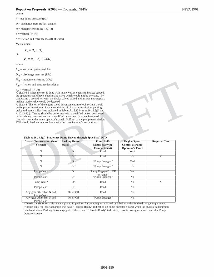
1901-150
Report on Proposals A2008 — Copyright, NFPA NFPA 1901
DRAFT
where:
P = net pump pressure (psi)
D = discharge pressure (psi gauge)
H = manometer reading (in. Hg)
L = vertical lift (ft)
F = friction and entrance loss (ft of water)
Metric units:
Or
where:
Pm = net pump pressure (kPa)
Dm = discharge pressure (kPa)
Hm = manometer reading (kPa)
Fm = friction and entrance loss (kPa)
Lm = vertical lift (m)A.16.13.6.5 When the test is done with intake valves open and intakes capped, the apparatus could have a bad intake valve which would not be detected. By conducting a second test with the intake valves closed and intakes not capped a leaking intake valve would be detected.A.16.13.8 The test of the engine speed advancement interlock system should verify proper functioning for the conditions of chassis transmission, parking brake and pump shift status indicated in Tables A.16.13.8(a), A.16.13.8(b) and A.16.13.8(c). Testing should be performed with a qualified person positioned in the driving compartment and a qualified person verifying engine speed control status at the pump operator’s panel. Shifting of the pump transmission/PTO should be done in accordance with the manufacturer’s instructions.
P D Hm m m= +
P D F Lm m m m= + + 9 8.
Table A.16.13.8(a) Stationary Pump Driven through Split-Shaft PTOChassis Transmission Gear
SelectedParking Brake Status
Pump Shift Status (Driving Compartment)
Engine Speed Control at Pump Operator’s Panel
Required Test
N On Road Yes ²
N Off Road No X
N On “Pump Engaged” Yes²
N Off “Pump Engaged” No
Pump Gear¹ On “Pump Engaged” “OK to Pump”
Yes
Pump Gear¹ Off “Pump Engaged” No
Pump Gear ¹ On Road No X
Pump Gear¹ Off Road No
Any gear other than N and Pump Gear¹
On or Off Road No
Any gear other than N and Pump Gear¹
On or Off “Pump Engaged” No
¹Chassis transmission shift selector placed in position for pumping as indicated on label provided in the driving compartment. ²Applies only for those apparatus that have “Throttle Ready” indication on pump operator’s panel when the chassis transmission is in Neutral and Parking Brake engaged. If there is no “Throttle Ready” indication, there is no engine speed control at Pump Operator’s panel.

1901-151
Report on Proposals A2008 — Copyright, NFPA NFPA 1901
DRAFT
Table A.16.13.8(b) Stationary Pump Driven through Transmission Mounted PTO, Front-of-Engine Crankshaft PTO, or Engine Flywheel PTO
Chassis Transmission Gear Selected
Parking Brake Status
Pump Shift Status (Driving Compartment)
Engine Speed Control at Pump Operator’s Panel
Required Test
N On Disengaged Yes¹
N Off Disengaged No X
N On “Pump Engaged” “OK to Pump”
Yes¹
N Off “Pump Engaged” No
Any gear other than N On “Pump Engaged” No X
Any gear other than N Off “Pump Engaged” No
Any gear other than N On or Off Disengaged No
¹ Applies only for those apparatus that have “Throttle Ready” indication on pump operator’s panel when the chassis transmission is in Neutral and Parking Brake engaged. If there is no “Throttle Ready” indication, there is no engine speed control at Pump Operator’s panel.
Table A.16.13.8(c) Stationary and “Pump-and-Roll” PumpChassis Transmission Gear
SelectedParking Brake Status Pump Shift Status
(Driving Compartment)Engine Speed Control at Pump Operator’s Panel
Required Test
N On Disengaged Yes¹
N Off Disengaged No X
N On “Pump Engaged” “OK to Pump” Yes¹
N Off “Pump Engaged” No
Any gear other than N On “Pump Engaged” “OK to Pump & Roll”
No X
Any gear other than N Off “Pump Engaged” “OK to Pump & Roll”
No
Any gear other than N On or Off Disengaged No
¹ Applies only for those apparatus that have “Throttle Ready” indication on pump operator’s panel when the chassis transmission is in Neutral and Parking Brake engaged. If there is no “Throttle Ready” indication, there is no engine speed control at Pump Operator’s panel.

1901-152
Report on Proposals A2008 — Copyright, NFPA NFPA 1901
DRAFT
A.16.13.9 If the tests of some components of the apparatus are being certified by an independent third-party certification organization, the purchaser might wish to specify that these tests also be certified by the independent third-party certification organization.
A.17.1 Auxiliary pumps come in a variety of different styles; gear, piston, and centrifugal designs are available. Where centrifugal designs are specified, the purchaser also has to select if it is to be a single stage, series-only multistage, or series/parallel multistage–type pump.
The purchaser should indicate the type of operation and performance required from the auxiliary pump. Auxiliary pumps are predominantly for fighting grass, brush and other small outside fires. Low capacity with high pressure through ¾ in. (19 mm) or 1 in. (25 mm) booster hose is commonly used for these fires. Pump-and-roll capability is often specified.
A.17.3 Various types of pump drive systems are available. These pumps are often driven by power takeoff units attached to SAE PTO openings on the chassis transmission. There are also front-of-engine PTO systems, flywheel PTO systems, split driveline PTO systems, and separate engine drive systems.
A.17.3.1 The volume and pressure that can be obtained safely depend on the torque capacity of the apparatus’s transmission or transfer case, power takeoff, and pump driveline. In most cases, the torque rating of the PTO will determine the maximum pump performance. Power takeoff manufacturers assign a torque rating to their products. This torque rating is based on intermittent service, as in operating the PTO at the full torque limit for a period of 5 minutes or less. For continuous duty, the intermittent torque rating is devalued 30 percent.
A.17.3.2 Sustained operations at either high volume, high pressure, or both high volume and high pressure could cause excessive heating of the transmission lubricant. To maintain lubricant temperatures below the component manufacturer’s published limits, it might be necessary to employ oil-to-oil or oil-to-water heat exchangers. The latter should be of a type that will not trap water, which would cause serious damage if the water is subsequently frozen.
A.17.5.1 The purchaser should indicate the number, size, and location of the pump intake connections or combination of connections desired. The types of pump intake connections are as follows:
(1) External intake
(2) Direct supply line from the water tank
(3) Supply line from the discharge side of the fire pump
A.17.6 The purchaser should indicate the size, number, and location of the pump discharge connections desired. The types of pump discharge connections are as follows:
(1) Discharge line(s) for nonpreconnected hose lines
(2) Discharge line(s) to preconnected hose lines
(3) Discharge line(s) to booster reel(s) (if provided)
A.17.6.3.1 For interoperability among fire departments at major incidents, National Hose threads are required. Adapters can then be used to adapt to locally used hose connections.
A.17.9.3 A separate pumping engine could use the vehicle chassis battery system, or it could have a separate set of dedicated batteries. Whichever system is used, battery charging and electrical supply should be designed to meet this standard.
A.18.2.2 Water tanks should have provisions that would allow for complete inside cleaning for flushing. The purchaser should indicate in the specifications if access to the interior of the tank is required.
A.18.2.3 Water tanks can appear in several different configurations, such as round, elliptical, rectangular, or T-shaped. Handling characteristics of the apparatus can be greatly affected by its vertical and horizontal centers of gravity. The purchaser should indicate the filling and dumping rates required if those rates exceed the requirements of this standard and any other local needs and let the apparatus manufacturer design the tank shape to best meet the axle-loading and center-of-gravity requirements.
When the tanks are made as one unit with the body and compartments, the material used is important. It should be corrosion proof and a material that does not easily sweat.
A.18.2.5 The design of a water tank can be a critical factor in the handling characteristics of fire apparatus. If water is free to travel either longitudinally or laterally in a tank, as would be the case if the tank were half full, a tremendous amount of inertia can be built up that will tend to force the fire apparatus in the direction the water has been traveling. When the water reaches the end of the tank, this sudden application of force can throw the fire apparatus out of control and has been known to cause fire apparatus to turn
over or skid when going around a curve or coming to a sudden stop. The only methods for preventing such accidents are to restrict or disrupt the movement of the water so that the inertia will not build up in one direction. This is done with the installation of swash partitions to either contain the water in smaller spaces within the tank (containment method) or disrupt its momentum by changing its direction of motion (dynamic method). The partitions in a containment system create compartments that are interconnected by openings between them so that air and water can flow at the specified rate when filling and emptying the tank. The partitions in a dynamic system are often staggered in an arrangement designed to change the direction of the water and turn it into a turbulent motion that absorbs much of its own energy.
A.18.3.3 A check valve installed in the tank-to-pump line is the most common method used to prevent water from backflowing into the tank at an excessive rate if the pump is being supplied from a hydrant or relay pumper and the tank-to-pump line valve has been inadvertently left in the open position.
A hole up to ¼ in. (6 mm) is sometimes provided in the check valve to release steam or other pressure buildup.
A.18.4.1 Where rapid filling of the water tank from an external source is desired, the purchaser should consider an inlet directly into the tank that is capable of allowing the tank to be filled at a rate of 1000 gpm (4000 L/min). Where such a fill connection is provided, it should conform to the requirements of 18.5.1.A.18.4.1.1 The intent of 18.4.1.1 is to allow filling the tank by the insertion of a common 2 1/2 in. (65 mm) hose with coupling into the fill opening. The opening does not need to be round in shape.
A.18.4.1.4 An excessive flow rate when filling a tank could result in a pressure buildup in the tank that could cause permanent damage or failure.
A.18.4.2.2 A vent/overflow outlet is necessary so that overpressurization does not occur within the tank while it is being filled. However, water is likely to spill out of the vent/overflow while the fire apparatus is moving (e.g., accelerating, decelerating, or cornering). The fill tower and vent/overflow outlet should be arranged so that water spillage is minimized and is directed behind the rear tires.
A.18.4.3.1 If a larger fill line is desired, the buyer should consult with the manufacturer on construction of the tank inlet location and any required reinforcement or alternation of the tank baffles. It is necessary to design the tank with venting and overflow capability for the maximum fill rate.
A.18.4.3.2 See A.18.4.3.1.
A.18.4.3.3 A locking-type ball valve, globe valve, needle valve, or other type of valve capable of regulating flows should be used. A gate valve is not recommended.
A.18.5.1.1 Where large filling rates are used, fill connections should be equipped with a diffuser inside the tank to minimize potential structural damage. It is important that the purchaser evaluate how the apparatus will be used and define the location and type of fittings desired on this tank fill.
Where rapid filling of the water tank on another type of apparatus from an external use is desired, the purchaser should consider an inlet directly into the tank that is capable of allowing the tank to be filled at a rate of 1000 gpm (4000 L/min). Where such a fill connection is provided, it should conform to the requirements of 18.5.1.
A.18.5.2 It is important that the purchaser evaluate how the apparatus will be used and define the location(s) and types of fittings for these outlets.
Where rapid dumping of the contents of the water tank to an external use is desired on other types of apparatus, the purchaser should consider an outlet directly into the tank that is capable of allowing water to be transferred from the tank at an average rate of at least 1000 gpm (4000 L/min).
A.18.5.2.2 Additional methods might be desired to improve the off-loading rate of gravity dumps. These methods include a jet assist or a pneumatic pump. Control should be from the pump operator’s position. Two types of jet assists can be used, one directed into the throat of the gravity dump and the other a peripheral jet system. Figure A.18.5.2.2(a) shows how the traditional jet is installed. A smooth-tipped “jet” nozzle is supplied by a pump that is capable of delivering at least 250 gpm (1000 L/min) at a gauge pressure of 150 psi (1000 kPa). Nozzle jets range in size from ¾ in. to 1¼ in. (19 mm to 33 mm). The diameter of the tip will be determined by the capacity of the pump being used and the diameter of the discharge piping and dump valve.
FIGURE A.18.5.2.2(a) Traditional Internal Jet Dump.[Existing Figure A.19.5.2.2(a), 2003 ed., (no change)]
The peripheral application of jet assist nozzles has proved highly effective. This approach utilizes two or more jets installed in the sides of the discharge

1901-153
Report on Proposals A2008 — Copyright, NFPA NFPA 1901
DRAFT
piping just outside the quick dump valve. In addition to the reported discharge advantages of peripheral discharge streams, the externally fed system is easier to plumb and has fewer maintenance problems. The jets, installed 25 degrees to 30 degrees from the piping wall, contact more surface area of the discharging water, thereby increasing water discharge efficiency. Because the water is drawn through the dump valve, less turbulence is created and the eddy effect often present with traditional in-line jets is overcome. Nozzles made by welding reducer pipe fittings work very effectively as jets. Flow rates of 2000 gpm (8000 L/min) have been obtained using a 300 gpm (1100 L/min) pump to supply two ¾ in. (19 mm) nozzles in a 6 in. (150 mm) dump valve configuration. Figure A.18.5.2.2(b) shows a diagram of a peripheral jet assist arrangement.
A pneumatic system can be used to pressurize a tank and assist in expelling water. The vacuum pumps can also be used for filling the tank.
FIGURE A.18.5.2.2(b) Peripheral Jet Assist Arrangement (Top View).[Existing Figure A.19.5.2.2(b), 2003 ed., (no change)]
A.18.6.1 If the tests of some components of the apparatus are being certified by an independent third-party certification organization, the purchaser might wish to specify that the water tank capacity also be certified by the independent third-party certification organization.
A.19.1 If the purchaser intends to suspend personnel or equipment from the aerial device using wire ropes or chains, the purchaser should inform the manufacturer of the intended use in order to determine proper mounting devices and locations as well as associated capacities. Equipment users have the potential to overload the aerial device components if improper methods are used.
A.19.2.3 The rated horizontal reach of the aerial ladder could be less than the extended length of the aerial that is used to determine the rated vertical height. This may be necessary to maintain the defined stability requirements as outlined in Section 19.21.
A.19.2.13 If the fire department expects to engage in operations where they will need to supply remote breathing air from the system on the aerial ladder to fire fighters working away from the end of an aerial ladder, such as during a rescue operation in a fuel or chemical tank, coal bin, or silo storage tower, it will be necessary to be able to supply breathing air for at least two persons.
A.19.3.4 Ladder capacity ratings are established in many different operating positions other than full extension and zero degrees elevation. Ladders are often rated at higher tip capacities as elevation angles increase or when the ladder is not fully extended. Most manufacturers provide distributed load capacities (several persons), depending on the ladder’s extension and elevation. Combination ratings that include capacity at the tip while discharging water are normally provided. These can vary with elevation and extension and are examples of multiple configurations. It is important that the manufacturer clearly define for the user the ladder’s rated capacity in various positions and operation modes.
A.19.4.3.1 A two-way communication system at two positions on the apparatus is considered a minimum. Depending on the configuration of the apparatus, the purchaser might want to consider communication systems at additional positions, such as at a pump panel or at the monitor operating position on the ladder.
A.19.5.2.1 Turntable bearing bolts are required to be checked and retorqued at regular intervals. The apparatus body should be constructed so as to make this task relatively simple by unbolting access panels, ladder slides, and other obstructions. Space should be provided for checking and torquing of the bearing bolts above and below the turntable using the appropriate tools.
A.19.5.4 The controls located at the tip of an aerial ladder are intended primarily to perform the final positioning of the aerial ladder in rescue or other fire-fighting operations. These controls are not intended to replace the lower control position as the primary operating position for the aerial ladder. Where the tip control is used, the operator(s) needs to take the following precautions: (1) Tip control operators need to be aware of personnel who are on the ladder sections behind them.
(2) Lower control operators need to remain in position and deactivate the tip controls when anyone is moving on the ladder.
(3) Tip control operators need to take care to place their feet on the steps at the tip to avoid injury to their feet from the moving ladder sections below.
(4) Tip control operators need to be belted in position to protect against abrupt or unexpected ladder movements.
A.19.6 The arrangement of the waterway could be a telescoping pipe to a fly section or a nontelescoping pipe to the tip of the base section.
A.19.6.3.5 The tip of an aerial ladder should be capable of being positioned up to a window or other location to allow fire fighters and civilians to climb onto the aerial ladder easily. It might be preferable to keep the monitor behind the last rung of the fly section to protect it in the road position.
A.19.6.5 The arrangement of the external inlet should be specified by the purchaser based on the intended local operation in supplying water to the waterway.
If the normal operations are to supply the waterway through the external inlet, a valve should be provided where large diameter hose is to be used. A valved three- or four-inlet siamese should be provided when 2½ in. or 3 in. (65 mm or 75 mm) supply lines are used. Attention should be given to the inlet arrangement to limit friction loss. Also, if the apparatus is equipped with a fire pump and the purchaser wants to use the auxiliary inlet as a discharge, a slow-operating valve needs to be installed in the riser to the swivel.
A.19.6.8 Where freezing conditions are expected, an automatic drain valve should be specified in order to drain the waterway when water is not flowing.
A. 19.7.3 The rated horizontal reach of the aerial platform may be less than the extended length of the aerial that is used to determine the vertical height. This may be necessary to maintain the defined stability requirements as outlined in Section 19.21.
A.19.9.2.1 A two-way communication system at two positions on the apparatus is considered a minimum. Depending on the configuration of the apparatus, the purchaser might want to consider communication systems at additional positions such as the pump panel.
A.19.10.1 Position lights on the outer corners of the platform can be helpful in providing increased visibility of the platform’s location from the ground operator’s position.
A.19.10.3.1 See A.19.5.2.1.
A.19.12.3.4 Because the water system can be closed at both the top and bottom of the waterway, the purchaser might want to require a vacuum relief valve.
A.19.12.5 The arrangement of the external inlet should be specified by the purchaser based on the intended local operation in supplying water to the waterway. If the normal operations are to supply the waterway through the external inlet, a valve should be provided where large diameter hose is to be used. A valved three- or four-inlet siamese should be provided when 2½ in. or 3 in. (65 mm or 75 mm) supply lines are used. Attention should be given to the inlet arrangement to limit friction loss. Also, if the apparatus is equipped with a fire pump and the purchaser wants to use the auxiliary inlet as a discharge, a slow-operating valve needs to be installed in the riser to the swivel.
A.19.12.9.1 Where freezing conditions are expected, an automatic drain valve should be specified in order to drain the waterway when water is not flowing.A.19.13.3 The rated horizontal reach of the water tower could be less than the extended length of the water tower that is used to determine the vertical height. This may be necessary to maintain the defined stability requirements as outlined in Section 19.21.
A.19.15.3.1 See A.19.5.2.1.
A.19.16.5 The arrangement of the external inlet should be specified by the purchaser based on the intended local operation in supplying water to the waterway. If the normal operations are to supply the waterway through the external inlet, a valve should be provided where large diameter hose is to be used. A valved three- or four-inlet siamese should be provided when 2½ in. or 3 in. (65 mm or 75 mm) supply lines are used. Attention should be given to the inlet arrangement to limit friction loss. Also, if the apparatus is equipped with a fire pump and the purchaser wants to use the auxiliary inlet as a discharge, a slow-operating valve needs to be installed in the riser to the swivel.
A.19.16.9 Where freezing conditions are expected, an automatic drain valve should be specified in order to drain the waterway when water is not flowing.
A.19.18.1 If the operator’s position is located on the turntable, the operator should have at least 5 ft2 (0.46 m2) of standing and working space exclusive of other space required. The purchaser should specify any special requirements for the operator’s position or for other space required on the turntable for personnel to stand or work.
A.19.18.2 Aerial ladder operational controls should be located such that the operator can see the tip of the aerial ladder in all operating positions. The operator’s position is often located on the turntable.
A.19.19.7 While this standard requires the hydraulic system to have adequate cooling for continuous operation for 2½ hours, prolonged operations under adverse environmental conditions could cause the hydraulic oil to rise in temperature beyond its recommended temperature range. The purchaser might wish to specify an indicator and an alarm that warns the operator if the fluid temperature begins to overheat.
1901-154
Report on Proposals A2008 — Copyright, NFPA NFPA 1901
DRAFT
A.19.20.1 Structural safety factors are widely recognized terms in good engineering practice but can be unfamiliar to those using this standard.
The following combination of loads should be evaluated to determine compliance with this standard. To clarify, the terms are defined as follows:
Dead Load Stress (DL). Stress produced by the aerial device structure and all materials, components, mechanisms, or equipment permanently fastened thereto. If this equipment is installed by the manufacturer before delivery, it is included in the dead load. Equipment added to the aerial device by the fire department that exceeds the manufacturer’s recommendations needs to be subtracted from the rated capacity.
Rated Capacity Stress (RL). Stress produced by the rated capacity of the aerial device applied at the tip of the fly section for an aerial ladder [minimum 250 lb (114 kg) at an elevation of zero degrees and full extension] or on the platform of an elevating platform apparatus [minimum 750 lb (340 kg) at an elevation of zero degrees and full extension].
Water Reaction Stress (WL). Stress produced by nozzle reaction force and the weight of the water in the water delivery system.
Material Yield Strength (FY). The stress at which a material exhibits a specified permanent distortion or set. (1) With no water in the system, the aerial device positioned at full extension, zero-degree elevation, and loaded at the rated capacity, the criterion for structural safety is as follows: the stress produced by two times the dead load stress (DL) plus the stress produced by two times the rated capacity stress (RL) should not exceed the material yield strength (FY), as shown in the following equation. This is a 2:1 safety factor.
(2) With water flowing in the system and the aerial device in the position that creates the highest stress, the criterion for structural safety is as follows: the stress produced by two times the dead load stress (DL) plus the stress produced by two times the rated capacity stress (RL) plus the stress produced by the water reaction stress (WL) should not exceed the material yield strength (FY), as shown in the following equation:
Other combinations of loading, including wind loads, ice loads, and impact loads, can be included as additional live loads in determining structural safety factors and rated capacities.
A.19.21.1 Water, hose, ground ladders, and other equipment on the apparatus all provide stability when they are in place. However, at a fire, this equipment and water are often removed. Therefore, stability needs to be measured under worst conditions, which is with the equipment removed.
A.19.24.2.8 The lifting of a tire or stabilizer on the opposite side of the apparatus from the load does not necessarily indicate a condition of instability.
A.19.25 The purchaser might wish to specify that this test be conducted with the certification tests required by Section 19.24 and the test results be certified by the independent third-party certification organization.
A.20.1.1 It is important for the purchaser to understand the types and properties of mechanical foam and its application to specify a foam proportioning system properly. Specific information regarding foam concentrates and their application is available in NFPA 11, Standard for Low-, Medium-, and High-Expansion Foam. Information on foam concentrates for Class A fires is available in NFPA 1150, Standard on Foam Chemicals for Fires in Class A Fuels.
The following terms are not used in this document but are associated with foam proportioning systems and are included here to aid understanding.
Aerated Foam. The end product of a discharge of foam solution and air.
Aspirate. To draw in air. Nozzle aspirating systems draw air into the nozzle to mix with the agent solution.
Aspirated Foam. The end product of a mechanically induced air stream that is drawn into the foam solution at atmospheric pressure to create foam. The aeration is generated by the energy of the foam solution stream.
Automatic Regulating Proportioning System. A proportioning system that automatically adjusts the flow of foam concentrate into the water stream to maintain the desired proportioning ratio. These automatic adjustments are made based on changes in water flow or conductivity.
Batch Mix. The manual addition of foam concentrate to a water storage container or tank to make foam solution.
Foam Blanket. A body of foam used for fuel protection that forms an insulating and reflective layer from heat.
Injector. A device used in a discharge or intake line to force foam concentrate into the water stream.
Manually Regulated Proportioning System. A proportioning system that requires manual adjustment to maintain the proportioning ratio when there is a change of flow or pressure through the foam proportioner.
Proportioning Ratio. The ratio of foam concentrate to water, usually expressed as a percentage.
Surface Tension. The elastic-like force in the surface of a liquid that tends to bring droplets together to form a surface.
Wetting Agent. A chemical that reduces the surface tension of water and causes it to spread and penetrate more effectively than plain water, but does not foam.
A.20.2 Foam proportioning systems can be designed with the following features:
(1) The ability to proportion different types of foam concentrate, including Class A and Class B foam concentrates
(2) The ability to proportion foam concentrate at fixed or variable proportioning ratios
(3) The ability to proportion foam concentrate into single or multiple discharge outlets
(4) The ability to supply foam solution and water simultaneously from multiple discharge outlets
(5) Manual or automatic foam proportioning system operation
A.20.2.1 In-line eductor foam proportioning systems are installed in the water pump discharge as a permanently installed device or as a portable device. Water is forced through the eductor venturi by water pump discharge pressure, creating a vacuum that causes foam concentrate to be pushed by atmospheric pressure into the eductor (into the water stream) at the design rate of the device [see Figure A.20.2.1(a)]. By design, a nonrecoverable pressure drop of 30 percent or greater is required for eductor operation. The maximum recovered pressure, including friction loss and static head pressure, is nominally 65 percent of the inlet pressure to the eductor. The in-line eductor is a manually regulated foam proportioning system.
FIGURE A.20.2.1(a) In-Line Eductor Foam Proportioning System.[Existing Figure A.21.2.1(a), 2003 ed., (no change)]
A variable flow bypass eductor system is a modification of the in-line eductor foam proportioning system. An eductor is placed in a bypass line around the main line water flow control valve so that when the valve is adjusted to produce water flow through the bypass eductor, foam concentrate is drawn into the eductor (into the water stream) [see Figure A.20.2.1(b)]. The foam solution in the bypass line is then joined with the main line water flow downstream of the water flow control valve. The variable flow bypass eductor is a manually regulated foam proportioning system.
A variable pressure eductor is another modification of the in-line eductor foam proportioning system. This type of eductor is designed to automatically adjust the area of the eductor venturi to compensate for changes in water pressure at the inlet of the device. Better performance (less pressure loss) can be achieved by having the eductor in the straight line position with the main line and the water flow control valve in the off-set position. The reason for this is that the small eductor sets the pressure drop and the water control valve merely matches the pressure losses of the eductor and fittings directing flow to the eductor. If the eductor flow has to flow through 2 branching tees and 2 elbows, the water control valve must match these pressure losses. If the eductor is in the straight line position pressure losses of 2 branching tees and 2 elbows are not present in the eductor branch of the variable flow bypass eductor; and therefore, the total pressure loss across the proportioning system is only that of the eductor. The variable pressure eductor is a manually regulated foam proportioning system.
FIGURE A.20.2.1(b) Variable Flow Bypass Eductor System.[Existing Figure A.21.2.1(b), 2003 ed., (no change)]
A.20.2.2 Self-educting master stream nozzles are mounted on the discharge side of the pump. These devices make up a complete foam proportioning system consisting of a foam proportioner and application device (nozzle). Self-educting master stream nozzles have the following operating characteristics:
(1) Automatic or operator-adjustable foam solution rates
(2) Minimal pressure drop
2 2× + × ≤DL RL FY
2 2× + × + ≤DL RL WL FY

1901-155
Report on Proposals A2008 — Copyright, NFPA NFPA 1901
DRAFT
A.20.2.3 An intake-side foam proportioning system is a manually regulated system. An in-line device installed in the water pump intake line provides a connection through a foam concentrate metering valve to the foam concentrate tank. The vacuum created by the water pump allows atmospheric pressure to push foam concentrate directly into the pump intake. Hydrant or relay operation is not possible with this type of foam proportioning system.
A.20.2.4 Around-the-pump proportioning systems operate with an eductor installed between the water pump discharge and the intake. A small flow of water from the water pump discharge passes through the eductor, which creates a vacuum that causes foam concentrate to be pushed into the eductor and discharged into the pump intake. Around-the-pump foam proportioning systems require a pressure differential of 30 percent to 50 percent of inlet pressure for efficient operation.
A manual around-the-pump proportioning system utilizes a manually adjustable foam concentrate metering valve to control the proportioning ratio. [See Figure A.20.2.4(a).]
FIGURE A.20.2.4(a) Manual Around-the-Pump Proportioning System.[Existing Figure A.21.2.4(a), 2003 ed., (no change)]
A flowmeter-sensing around-the-pump proportioning system utilizes a flowmeter-sensing system to monitor total solution flow and foam concentrate flow. The flow data are transmitted to an electronic control that controls the proportioning ratio through a foam concentrate metering valve. [See Figure A.20.2.4(b).]
FIGURE A.20.2.4(b) Flowmeter Sensing Around-the-Pump Proportioning System.
[Existing Figure A.21.2.4(b), 2003 ed., (no change)]
A.20.2.5 Balanced pressure foam proportioning systems are installed on the discharge side of the water pump. Two orifices discharge water and foam concentrate into a common ratio controller (proportioner) located in the water pump discharge. By adjusting the area of the orifices to a particular ratio, the percentage of injection can be controlled if the intake pressures are equal. The method of controlling or balancing the foam concentrate pressure with the water pressure varies with different balanced pressure system designs. The two basic types of balanced pressure systems are systems without a foam concentrate pump and systems with a concentrate pump. Balanced pressure foam proportioning systems generally are automatic regulating foam proportioning systems.
Balanced pressure systems without a foam concentrate pump are referred to as “pressure proportioning systems” [see Figure A.20.2.5(a)]. These systems utilize a pressure vessel with an internal bladder to contain the foam concentrate. When in operation, water pump pressure is allowed to enter the pressure vessel between the shell and the internal bladder to exert pressure on the internal bladder. The foam concentrate is forced out of the bladder to the foam proportioner at a pressure equal to the water pump pressure.
Two basic types of balanced pressure foam proportioning systems utilize a foam concentrate pump: a bypass system and a demand system. Foam proportioning system operation is not affected by water pump intake pressure or interrupted while refilling the foam concentrate tank in these types of foam proportioning systems.
The bypass system utilizes a valve in the foam concentrate pump recirculating line that balances the foam concentrate and water pressure by bypassing excess foam concentrate. [See Figure A.20.2.5(b).]
The demand system is designed to control the speed of the foam concentrate pump, resulting in control of the pump discharge pressure to achieve a balance of foam concentrate and water pressure within the system. [See Figure A.20.2.5(c).]
FIGURE A.20.2.5(a) Pressure Proportioning Balanced Pressure Proportioning System.
[Existing Figure A.21.2.5(a), 2003 ed., (no change)]
FIGURE A.20.2.5(b) Bypass Balanced Pressure Proportioning System.[Existing Figure A.21.2.5(b), 2003 ed., (no change)]
FIGURE A.20.2.5(c) Demand Balanced Pressure Proportioning System.[Existing Figure A.21.2.5(c), 2003 ed., (no change)]
A.20.2.6 Direct injection foam proportioning systems utilize a foam concentrate pump to inject foam concentrate directly into the water pump
discharge. Foam proportioning system operation is not affected by water pump intake pressure or interrupted while refilling the foam concentrate tank. Direct injection foam proportioning systems generally are automatic regulating foam proportioning systems.
Automatic flow-sensing direct injection foam proportioning systems utilize an in-line flowmeter(s) to monitor the system operating conditions. System operating data are transmitted to an electronic control, which controls the proportioning ratio. Two different flow-sensing systems are available:
(1) An electronic control receives electronic signals corresponding to the proportioning ratio from the control panel and water flow data from the flowmeter. The electronic control then commands the foam concentrate pump module to deliver foam concentrate at the proportional rate. [See Figure A.20.2.6(a).]
(2) An electronic control receives electronic signals corresponding to the foam concentrate flow from a foam concentrate flowmeter, the proportioning ratio from the control panel, and water flow data from the water flowmeter. The electronic control controls the proportioning ratio through a foam concentrate metering valve. [See Figure A.20.2.6(b).]
FIGURE A.20.2.6(a) Single-Meter Flow-Sensing Direct Injection Foam Proportioning System.
[Existing Figure A.21.2.6(a), 2003 ed., (no change)]
FIGURE A.20.2.6(b) Dual-Meter Flow-Sensing Direct Injection Foam Proportioning System.
[Existing Figure A.21.2.6(b), 2003 ed., (no change)]
A conductivity-sensing direct injection foam system utilizes an electrical conductivity sensor(s) to sample the fire pump discharge water prior to foam concentrate injection and transmits this information to an electronic control. A second electrical conductivity sensor samples the foam solution and transmits this information to the electronic control that controls the foam pump motor speed based on the ratio selected by the operator. Since flow rate affects conductivity readings, a flow meter transmits the flow rate through the process manifold to the electronic control. [See Figure A.20.2.6(c)]
FIGURE A.20.2.6(c) Conductivity-Sensing Direct Injection Foam Proportioning System.
A.20.2.7 In a water motor foam proportioning system, a water motor drives a positive displacement foam concentrate pump. The water motor can be of either a positive displacement type or a turbine type. Water motor foam proportioning systems are automatic regulating foam proportioning systems.
Where a positive displacement water motor drives the foam concentrate pump, the ratio of the water motor displacement to the displacement of the foam concentrate pump is the ratio of the desired foam solution. A positive displacement water motor proportioning system requires no external power. [See Figure A.20.2.7(a).]
FIGURE A.20.2.7(a) Water Motor Foam Proportioning System.[Existing Figure A.21.2.7(a), 2003 ed., (no change)]
Flowmeter
Water/foam discharge
Water suction
Pressure vacuum vent
Concentratetank
Tank drain
Tank shutoff
Foam Water
Strainer
Pressure gauge
Electronic control
D
M
Display
Electric
Key:
Conductivitymeter
Conductivitymeter
Variable flow rate concentrate
pump
Compound gauge
Water pump

1901-156
Report on Proposals A2008 — Copyright, NFPA NFPA 1901
DRAFT
A water turbine–driven foam proportioning system uses a water turbine to power a positive displacement foam concentrate pump. Flowmeters sense the foam concentrate pump output and the water flow, sending signals to an electronic control that controls the proportioning ratio by adjusting the water turbine speed. [See Figure A.20.2.7(b).]
FIGURE A.20.2.7(b) Water Turbine–Driven Flow-Sensing Direct Injection Foam Proportioning System.
[Existing Figure A.21.2.7(b), 2003 ed., (no change)]
A.20.3.1 Foam proportioning systems that inject foam concentrate into the water pumping system at a higher pressure than the water pressure have the potential to force foam concentrate or foam solution into an external water source. This condition will occur when there is no water flowing and the foam proportioning system is activated in the automatic mode. Backflow prevention devices, or any device that creates additional friction loss in the system, should be installed only with the approval and specific instructions of the foam proportioning system manufacturer.
A.20.3.4 Most foam concentrate manufacturers differentiate between the materials they recommend for foam proportioning system components that are designed to be flushed with water after operation and those components that are intended to be continuously wetted with foam concentrate.
A.20.4.1 It is desirable to have a visual indicator on the operator’s panel that shows whether the foam proportioning system is in the “operating” position or the “off” position. A visual means of indicating positive foam concentrate flow at the operator’s panel is also helpful.
A.20.6.3.2 Suitable means to attach the cover to the fill tower could include use of a threaded cap or a hinged cover with a mechanical latching device.
A.20.6.6 On fire apparatus where a single foam storage tank is used, provisions should be made to flush the tank and all foam concentrate plumbing to avoid contamination of dissimilar foam concentrates when switching types or brands.
A.20.6.8 The foam concentrate tank(s) can be an integral part of the water tank.
A.20.6.10.2 Different types and brands of concentrates can be incompatible with each other and should not be mixed in storage. Concentrate viscosity varies with different types of products and temperatures.
A.20.7 The foam concentrate pump is a critical component of both balanced pressure and direct injection foam proportioning systems. Positive displacement pumps are recommended for several reasons. Positive displacement pumps are relatively slow in speed compared to centrifugal pumps, which is advantageous with viscous foam concentrates that are difficult to shear. Centrifugal pumps can become air bound when trying to pump viscous foam concentrates, which results in a complete shutdown of the system. The self-priming feature of positive displacement pumps allows them to draw foam concentrate from drums or any external source without priming the pump.
A.20.7.2 Corrosion-resistant materials are materials such as brass, copper, monel, stainless steel, or equivalent materials.
A.20.7.5 A suitable suction device is required to operate from an external source such as 5 gal (19 L) pails, 55 gal (208 L) drums, and portable tanks or containers.
A.20.9.3(5) It is necessary for the operator be familiar with the specific types of foam concentrates the foam proportioning system manufacturer has designed the system to operate with and proportion accurately. The foam proportioning system may require modification or recalibration if a foam concentrate is introduced into the system. that was not intended by the system’s manufacturer for use in the system.
A.20.10 If the tests of some components of the apparatus are being certified by an independent third-party certification organization, the purchaser might wish to specify that these tests also be certified by the independent third-party certification organization.
A.20.10.1 There are four methods for testing a foam proportioning system for calibration accuracy. They are:(1) Substituting Water for Foam Concentrate.(2) Measuring Foam Concentrate Pump Output Directly(3) Determining Foam Percentage by Use of a Refractometer.(4) Determining Foam Percentage by Use of a Conductivity Meter.
Test Method 1: Substituting Water for Foam Concentrate. The foam proportioning system is operated at the water flow rates at which the system is to be tested. Water is used as a substitute for foam concentrate. The substitute water for the foam concentrate is drawn from a calibrated tank instead of foam concentrate from the foam concentrate tank. The volume of water drawn from the calibrated tank divided by the volume of water pumped over the
same time period multiplied by 100 represents the percentage of foam the foam proportioning system is producing.
Test Method 2: Measuring Foam Concentrate Pump Output Directly. With some direct-injection systems, it is possible to directly measure the foam concentrate pump output. With the foam proportioning system operating at a given water flow rate, and either foam concentrate or water used as a substitute for foam concentrate, the output of the foam concentrate pump is measured by diverting that output into a calibrated container for direct measurement over a measured period of time. An alternative is to measure the foam concentrate flow or water substitute with a calibrated meter.
Test Method 3: Determining Foam Percentage by Use of a Refractometer. A refractometer is used to measure the refractive index of a foam solution sample.
First, a base calibration curve is prepared using the same water and foam concentrate that will be used with the system to be tested. Three known foam solution samples are needed and should include the following:
(1) The nominal intended percentage
(2) The nominal intended percentage plus 1 percent
(3) The nominal intended percentage minus 1 percent
If the nominal intended percentage is 1 percent or less, the three samples should be as follows:
(1) The nominal intended percentage
(2) The nominal intended percentage plus 0.3 percent
(3) The nominal intended percentage minus 0.3 percent
The required amount of water is placed in a 100 mL or larger graduated cylinder leaving space for the foam concentrate. A 10 mL pipette or 10 cc syringe is used to carefully add the required amount of foam concentrate to the water. Each measured foam solution is then poured from the graduated cylinder into a 100 mL or larger plastic bottle, and the bottle is marked indicating the percentage solution it contains. The bottle is capped and thoroughly shaken to mix the foam solution.
An alternative method for making the three foam solution samples is to use a very accurate scale. The density of the foam concentrate needs to be known and can be found on the product data sheet or the Material Safety Data Sheet (MSDS) for the foam concentrate. For example, to make a 100 ml sample of a 3 percent foam solution using a foam concentrate with a density of 1.04, 97 g of water is measured into a beaker and 3.12 g of foam concentrate is added to the beaker (1.04 x 3 g = 3.12 g).
After the foam solution samples are thoroughly mixed, a refractive index reading is taken of each foam solution sample. This is done by placing a few drops of the solution on the refractometer prism, closing the cover plate, and observing the scale reading at the dark field intersection. Because the refractometer is temperature compensated, it could take 10 seconds to 20 seconds for the sample to be read properly. It is important to take all refractometer readings at ambient temperatures of 50°F (10°C) or above.
Using standard graph paper, the refractive index readings are plotted on one axis and the percentage of concentration on the other. This plotted curve serves as the known baseline for the test series. The solution samples should be set aside in the event the measurements need to be checked.
Foam solution samples are then collected from the proportioning system, making certain that the samples are taken at an adequate distance downstream from the foam proportioning system being tested to allow for complete mixing of the water and the foam concentrate. Refractive index readings of the samples are taken and compared to the plotted curve to determine the percentage of foam.
This method might not be accurate for AFFF, alcohol-resistant foam, or certain other types of foam that typically exhibit very low refractive index readings. Also, the refractometer method should not be used when testing foam percentages of 1 percent or lower because the accuracy for determining the percentage of foam concentrate in a solution when using a refractometer is ±0.1 percent, at best. For this reason, Test Method 4, the conductivity method, might be preferable where AFFF, alcohol-resistant foam, or 1 percent or less foam (Class A foam) is to be tested.
Test Method 4: Determining Foam Percentage by Use of a Conductivity Meter. The conductivity test method is based on changes in electrical conductivity as foam concentrate is added to water. Conductivity is a very accurate method, provided there are substantial changes in conductivity as foam concentrate is added to the water in relatively low percentages. Because saltwater and brackish water are very conductive, this method might not be suitable where these waters are used because of the small conductivity changes as foam concentrate is added. If saltwater or brackish water is used, it is necessary to make foam solutions in advance to determine if adequate changes in conductivity can be detected. This method cannot be used if the

1901-157
Report on Proposals A2008 — Copyright, NFPA NFPA 1901
DRAFT
water has more total solids than the foam concentrate.
The following three variations of this test method can be used to determine the foam percentage by the conductivity method:(1) Direct Reading Conductivity Method. A sample of the water to be used in the test is put in a 100 mL or larger container. The conductivity meter head is immersed in the water sample, and the meter display is set at zero. If the direct reading foam solution conductivity meter is mounted in a discharge line, the meter should be set at zero with plain water flowing. If the conductivity meter manufacturer does not indicate that the percentage of foam solution can be read directly for the foam concentrate being used, a calibration curve needs to be developed. The calibration curve might show that the direct meter readings are correct for the foam concentrate being used, or it might indicate that the calibration curve needs to be used when that foam concentrate is used in the test.
The foam proportioning system is operated, and a sample of the foam solution produced by the system is collected using a 100 mL or larger container. The conductivity meter head is immersed in the foam solution sample, and the percentage of the foam solution is read on the meter display. If the conductivity meter is mounted in a discharge line, the percentage of the foam solution is read on the meter display while foam solution is being discharged.
(2) Conductivity Comparison Method. A sample of the water to be used in the test is put in a 100 mL or larger container. Using a conductivity meter reading in microsiemens per centimeter (mscm), the conductivity valve of the water sample is determined. The foam proportioning system is operated, and a sample of the foam solution produced by the system is collected in a 100 mL or larger container. Using the conductivity meter, the conductivity value of the foam solution sample is determined. The conductivity value of the water sample is subtracted from the conductivity value of the foam solution sample, and the result is divided by 500 to obtain the percentage of foam concentrate in the solution.
Note that the divisor is 500 only if the conductivity meter units are microsiemens per centimeter. Other units of conductivity can be used, but the value of the divisor (500) will need to be adjusted.
(3) Conductivity Calibration Curve Method. A base calibration curve is prepared using the water and foam concentrate from the system to be tested. Three known foam solution samples are made using the procedure in Test Method 3. After the foam solution samples are thoroughly mixed, the conductivity of each solution is measured using a conductivity meter. Care should be taken to ensure that the proper procedures are used for taking readings and that the meter is switched to the correct conductivity range. Most synthetic-based foams used with freshwater result in foam solution conductivity readings of less than 2000 mscm. Protein-based foams used with freshwater generally produce conductivity readings in excess of 2000 mscm. Because of the temperature-compensation feature of the conductivity meter, it could take a short time to obtain a consistent reading.
Once the solution samples have been measured and recorded, the bottles should be set aside as control sample references. The conductivity readings then should be plotted on standard graph paper. It is more convenient to place the foam solution percentage on the horizontal axis and the conductivity readings on the vertical axis.
A straight line should be drawn that approximates the connection of all three points. While it might not be possible to connect all three points with a straight line, they should be very close. If not, the conductivity measurements should be repeated, and, if necessary, new control sample solutions should be prepared and used until all three points plot in a nearly straight line. This plot serves as the known base (calibration) curve to be used for the test series.
Once a base curve has been plotted, foam solution samples are collected from the proportioning system. The conductivity of the test samples is measured, and the percentage of foam solution is determined from the base curve. Foam solution samples that have been allowed to drain from expanded foam should not be used, because they can produce misleading conductivity readings.A.20.10.1.2 Depending on the foam proportioner technology, the manufacturer could require the system to be calibrated at the low end, high end or somewhere midrange, to ensure the system meets the accuracy requirements in the standard. For example, if the system runs richer as percentages increase, the manufacturer could anchor the low percentage during calibration. Therefore the manufacturer needs to have the flexibility to pick this point, knowing how his technology reacts over the full operating range.A.20.11.1(2) The user may wish to specify additional test points and viscosities to ensure that user’s full range of operational requirements are satisfied.A.20.11.1(3). See A.20.10.1.
A.21.1 The following terms are not used in this document but are associated with CAFS and are included here to aid in understanding.(1) CAFS-Capable. A compressed air foam system (CAFS)-capable fire
apparatus is a fire apparatus equipped with the following:a. Automatic regulating foam proportioning system capable of injecting foam concentrate into the discharge or pressure side of the pumpb. Air compressor with the capacity to supply the required scfm and automatic air pressure controlsc. Controls to mix the air and foam solution
(2) Chatter. An unacceptable flow condition wherein air is not fully mixed with the foam solution.
(3) High-Energy Foam Generator. A foam generator that uses a large amount of external energy to aerate the foam.
(4) Low-Energy Foam Generator. A foam generator that uses energy of the foam stream to aerate the foam.
(5) Mixing Chamber. A device used to produce fine, uniform bubbles in a short distance as foam solution and air flow through it.
(6) Scrubbing. The process of agitating foam solution and air in a confined space such as a hose, pipe, or mixing chamber to produce tiny, uniform bubbles.
(7) Slug Flow. The discharge of distinct pockets of water and air due to the insufficient mixing of foam concentrate, water, and air in a compressed air foam system.
(8) Surge. The sudden decompression of a discharge line caused by the rapid opening of the discharge appliance.
A.21.2.4 It is recommended that compressed air not be injected into the discharge piping until the flow of foam solution has been established. The nozzle reaction at the end of a hose can be quite high if air and water are flowing in the discharge line. The nozzle reaction could be a safety issue with an operator that is not expecting or not properly braced to withstand this reaction force. The reaction force is substantially reduced when a foam solution is flowing in the discharge hose. Also a charged CAFS line should be opened slowly to lower the nozzle reaction force that can be very high if opened rapidly.
A.21.2.5 Pressure in the form of compressed air can remain trapped in a CAFS as a result of deactivating the system. It is important for the operator to relieve any pressure in the foam proportioning system and connected hose lines before disconnecting hose lines or performing any operation that opens the system to atmosphere.
A.21.4 If the expansion ratio is to be tested, the following equipment and test procedures are recommended:
(1) Gram scale, 1500 g capacity accurate to 0.1 g.
(2) One 1000 mL container that can be struck at 1000 mL (a 1000 mL graduated cylinder cut off at 1000 mL works well).
The empty container is placed on the scale, and the scale is set to zero. Using the container, a full sample of foam is collected and the foam is struck at the 1000 ml level. The container is placed on the scale and the mass is read in grams.
The foam mass in grams assumes that 1 g of foam solution occupies 1 mL of volume.
A.21.5 Any components of the piping system exposed to pressurized air from the CAFS should be designed for a burst gauge pressure of at least 500 psi (3400 kPa).
A.21.7.6 Some systems provide automatic regulation of the water flow; however, instrumentation is still useful to the operator. Even automatic systems have adjustments and performance limits that warrant instrumentation. Where the system design does not allow for such automatic regulation, or where the operator has the ability to control water flow or airflow, air and water flowmeters are necessary for the operator to monitor the operational performance of the CAFS where the nozzle person cannot be seen. Where pumping long hose lays or pumping to great heights, the operator needs to know what is flowing in order to be certain the proper product is being delivered.
A.21.9 If the tests of some components of the apparatus are being certified by an independent third-party certification organization, the purchaser might wish to specify that these tests also be certified by the independent third-party certification organization.
A.21.9.1.3.3 Care should be taken to avoid injuries to personnel from the discharging airstream. Only those persons actually conducting the tests should be in the test area, and they should wear protection for their ears, eyes, and face from noise and dust during the airflow test.
%foam=Conductivity of foam solution-Conductivity of water
5000
ExpansionFoam mass in grams
= 1000

1901-158
Report on Proposals A2008 — Copyright, NFPA NFPA 1901
DRAFT
A.22.1 A typical electrical system might consist of a generator system that is bonded to the chassis frame rail. Conductors making up the power supply assembly include the neutral conductor (N), grounding conductor (G), and line voltage conductors (L1, L2, L3).
The neutral conductor of the power supply assembly is grounded to the generator frame. This is the only location that the neutral conductor is grounded in the entire system. The power supply assembly terminates at the panelboard for distribution to the rest of the system. Figure A.22.1 shows a typical system on a fire apparatus.
FIGURE A.22.1 Typical Line Voltage Electrical System.
It is the responsibility of the purchaser to provide the contractor with sufficient information to enable the contractor to supply an electrical system that will meet the needs of the fire department.
For each piece of line voltage electrical equipment installed on the apparatus or operated using the apparatus line voltage electrical system, the purchaser should provide the following information: (1) The type of electrical current required, that is, alternating current (ac), direct current (dc), or either ac or dc, as follows:
(a) If ac is required, the nominal operating voltage, the maximum amperage, and whether it is single-phase or three-phase. For electronic equipment and some motors, the required quality of the ac power should also be stated, including the upper and lower limits of voltage and the allowable variation of frequency and wave form.
(b) If dc is required, the nominal operating voltage and the maximum operating current. For special equipment, the required quality of the dc power should also be stated, including the upper and lower limits of voltage and the amount of ripple voltage.
(2) The required minimum continuous output wattage of the electrical source or sources that power the system, or if more than one type of current or voltage is required, the maximum output wattage for each type of current or voltage.
Generally, the line voltage electrical system should be sized based on the total amount of fixed and portable equipment that is likely to be operated at the same time. In view of the increasing use of line voltage devices on apparatus, the provision of a line voltage electrical system of sufficient capacity is strongly recommended.
Where only incandescent lighting is involved, ac or dc power can be used. Where other electrical devices such as motor-driven equipment or electronic equipment are involved, single-phase ac power at 60 Hz is normally required. However, because of the substantial reduction of size and cost that results
from three-phase operation, ac motors larger than 5 hp are usually designed to operate on three-phase ac current. Attempting to operate electrical equipment using the wrong type of electrical power will almost always damage the electrical equipment.
The following factors are guidelines for determining the line voltage electrical loads present on an apparatus and determining the size of power source required. Various electrical loads are placed on apparatus for specific purposes yet a number are installed for convenience usage. The purchaser should start by creating a tabulated list of line voltage electrical items (lights, cord reels, receptacles, etc.) and their wattage ratings so a total electrical load can be determined. It is the responsibility of the purchaser to specify the ratings to be used when calculating power source loads.Loads or Receptacles. For plug connected equipment and receptacles, either work with the loads that can be connected or with the power available from receptacles that could have equipment connected to them. Do not add both in the calculation. If the power source will normally power only equipment carried on that piece of apparatus, use a total of loads carried on the apparatus. If the power source might power equipment carried on other apparatus as well, work with the total capacity represented by the receptacles provided. Fixed loads permanently connected are always included.Fixed mounted lighting. All lighting that is mounted directly to the apparatus should be itemized with the manufacturer’s wattage ratings. This includes light towers, brow lights, scene lights, and interior lights.Removable lighting. All lights mounted on the apparatus using a plug and receptacle connection scheme should be itemized with the light manufacturer’s wattage rating. This includes tripod lights mounted on the top or back of apparatus bodies that can be unplugged, removed from the apparatus, set up on the ground or inside a building, and powered with the use of an extension cord.Dedicated receptacles. For receptacles located and intended to always power a specific piece of equipment such as a hydraulic rescue tool (HRT) power unit, battery charger, light, or other piece of equipment, use the wattage of the connected equipment. Cord reels. Rate cord reels to their circuit breaker rated amperage when determining generator loads. Wattage rating should be voltage times circuit breaker amperage. For 120/240 volt cord reels, use 240 times the circuit breaker rating.“Side of body” receptacles. Rate “side of body” receptacles at half their amperage capacity when determining generator loads. If specific devices will be connected to a “side of body” receptacles most of the time, the higher wattage rating of the specific device should be used.
Power supply assembly
Neutral conductor
Grounding conductor
Line voltage conductors
Line voltage conductors
Body bondCab bond
Chassis frame rail is common bond conductor.
Generatorbond
144 in. (3660 mm) maximum distance
Manual reset — main power source overcurrent protection device
Distribution box Main power source overcurrent device can be in distribution box if within 144 in. (3660 mm) of power source.
Receptacles
Hardwired appliances
G
L1
L2
N
Generator frame No connection between neutraland generator frame
G L1 NL2
Shore-powerinlet
LNG
Shore-powerinlet
LNG
Dualpowered
equipment
Transfer switch Bonded tovehicle frame
Bonded tovehicle frame
ORShore
poweredequipment
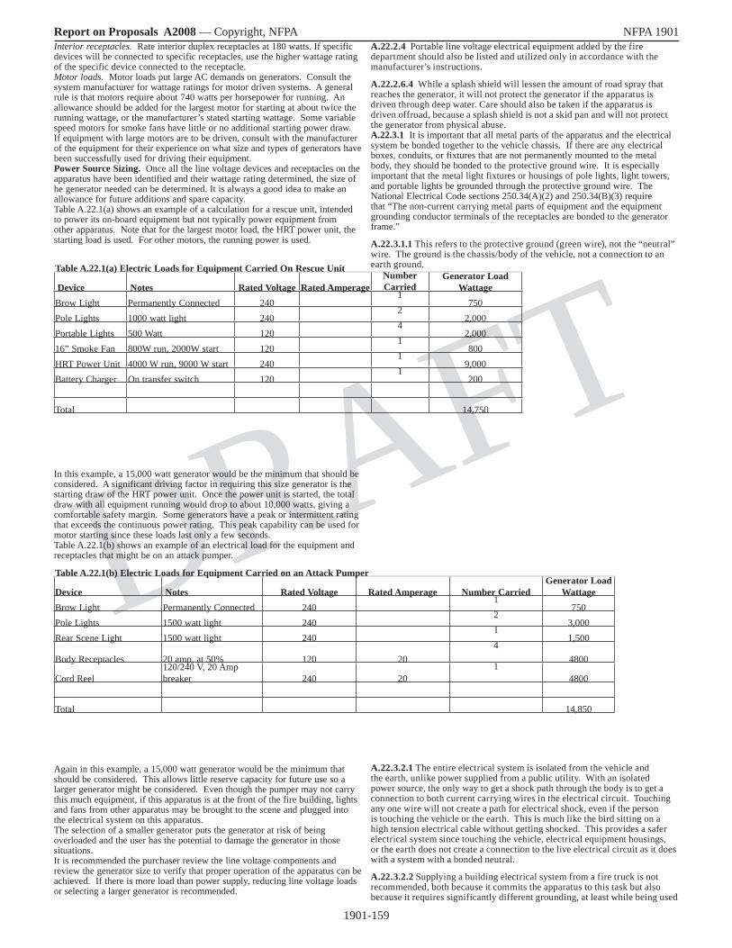
1901-159
Report on Proposals A2008 — Copyright, NFPA NFPA 1901
DRAFT
Interior receptacles. Rate interior duplex receptacles at 180 watts. If specific devices will be connected to specific receptacles, use the higher wattage rating of the specific device connected to the receptacle.Motor loads. Motor loads put large AC demands on generators. Consult the system manufacturer for wattage ratings for motor driven systems. A general rule is that motors require about 740 watts per horsepower for running. An allowance should be added for the largest motor for starting at about twice the running wattage, or the manufacturer’s stated starting wattage. Some variable speed motors for smoke fans have little or no additional starting power draw. If equipment with large motors are to be driven, consult with the manufacturer of the equipment for their experience on what size and types of generators have been successfully used for driving their equipment.Power Source Sizing. Once all the line voltage devices and receptacles on the apparatus have been identified and their wattage rating determined, the size of he generator needed can be determined. It is always a good idea to make an allowance for future additions and spare capacity.Table A.22.1(a) shows an example of a calculation for a rescue unit, intended to power its on-board equipment but not typically power equipment from other apparatus. Note that for the largest motor load, the HRT power unit, the starting load is used. For other motors, the running power is used.
In this example, a 15,000 watt generator would be the minimum that should be considered. A significant driving factor in requiring this size generator is the starting draw of the HRT power unit. Once the power unit is started, the total draw with all equipment running would drop to about 10,000 watts, giving a comfortable safety margin. Some generators have a peak or intermittent rating that exceeds the continuous power rating. This peak capability can be used for motor starting since these loads last only a few seconds.Table A.22.1(b) shows an example of an electrical load for the equipment and receptacles that might be on an attack pumper.
Again in this example, a 15,000 watt generator would be the minimum that should be considered. This allows little reserve capacity for future use so a larger generator might be considered. Even though the pumper may not carry this much equipment, if this apparatus is at the front of the fire building, lights and fans from other apparatus may be brought to the scene and plugged into the electrical system on this apparatus.The selection of a smaller generator puts the generator at risk of being overloaded and the user has the potential to damage the generator in those situations.It is recommended the purchaser review the line voltage components and review the generator size to verify that proper operation of the apparatus can be achieved. If there is more load than power supply, reducing line voltage loads or selecting a larger generator is recommended.
A.22.2.4 Portable line voltage electrical equipment added by the fire department should also be listed and utilized only in accordance with the manufacturer’s instructions.
A.22.2.6.4 While a splash shield will lessen the amount of road spray that reaches the generator, it will not protect the generator if the apparatus is driven through deep water. Care should also be taken if the apparatus is driven offroad, because a splash shield is not a skid pan and will not protect the generator from physical abuse.A.22.3.1 It is important that all metal parts of the apparatus and the electrical system be bonded together to the vehicle chassis. If there are any electrical boxes, conduits, or fixtures that are not permanently mounted to the metal body, they should be bonded to the protective ground wire. It is especially important that the metal light fixtures or housings of pole lights, light towers, and portable lights be grounded through the protective ground wire. The National Electrical Code sections 250.34(A)(2) and 250.34(B)(3) require that “The non-current carrying metal parts of equipment and the equipment grounding conductor terminals of the receptacles are bonded to the generator frame.”
A.22.3.1.1 This refers to the protective ground (green wire), not the “neutral” wire. The ground is the chassis/body of the vehicle, not a connection to an earth ground.
A.22.3.2.1 The entire electrical system is isolated from the vehicle and the earth, unlike power supplied from a public utility. With an isolated power source, the only way to get a shock path through the body is to get a connection to both current carrying wires in the electrical circuit. Touching any one wire will not create a path for electrical shock, even if the person is touching the vehicle or the earth. This is much like the bird sitting on a high tension electrical cable without getting shocked. This provides a safer electrical system since touching the vehicle, electrical equipment housings, or the earth does not create a connection to the live electrical circuit as it does with a system with a bonded neutral.
A.22.3.2.2 Supplying a building electrical system from a fire truck is not recommended, both because it commits the apparatus to this task but also because it requires significantly different grounding, at least while being used
Table A.22.1(a) Electric Loads for Equipment Carried On Rescue Unit
Device Notes Rated Voltage Rated AmperageNumber Carried
Generator Load Wattage
Brow Light Permanently Connected 2401
750Pole Lights 1000 watt light 240
22,000
Portable Lights 500 Watt 1204
2,00016” Smoke Fan 800W run, 2000W start 120
1800
HRT Power Unit 4000 W run, 9000 W start 2401
9,000Battery Charger On transfer switch 120
1200
Total 14,750
Table A.22.1(b) Electric Loads for Equipment Carried on an Attack Pumper
Device Notes Rated Voltage Rated Amperage Number CarriedGenerator Load
WattageBrow Light Permanently Connected 240
1750
Pole Lights 1500 watt light 2402
3,000Rear Scene Light 1500 watt light 240
11,500
Body Receptacles 20 amp, at 50% 120 204
4800
Cord Reel120/240 V, 20 Amp breaker 240 20
14800
Total 14,850

1901-160
Report on Proposals A2008 — Copyright, NFPA NFPA 1901
DRAFT
for this application, in accordance with the National Electrical Code section 250.20, “Alternating-Current Circuits and Systems to Be Grounded,” and other applicable sections of NFPA 70.A.22.3.3 Ground fault circuit interrupters (GFCIs) are intended to provide protection from electrical shock, but experience in the fire service has pointed out several disadvantages with using them. (1) They introduce the possibility of unwanted trips that shut off electricity and thus lights or other power being used for emergency operations. (2) The risk of electrical shock due to a fault through a firefighter to ground (earth) is much less in the typical fireground situation with a vehicle mounted generator than it is with utility supplied power because the vehicle mounted generator is not connected to an earth ground, thus the potential shock path through a firefighter to the earth generally does not have the necessary path back to the generator to produce a shock. (3) With an isolated line voltage system as required in section 22.3.2.1, a potential path through a person to either the earth ground or the vehicle body does not create a shock hazard. It is almost impossible to create a condition that will trip a GFCI connected to an isolated line voltage system.(4) Due to the presence of water in the fireground environment, GFCIs are much more prone to trips due to leakage currents that do not involve personnel, and thus do not present a safety risk. In an isolated system this leakage to ground will not occur, through a water path or through a firefighter. (5) GFCIs might not compatible with 120/240 volt 4 wire cord reels frequently used in the fire service unless the GFCI is located at the end of the cord reel. This location does have the advantage that it puts the reset function closer to the user, but it also exposes the delicate electronics of the GFCI to water and physical damage. (6) Since most plugs and receptacles used in the fire service are twist lock instead of standard nonlocking household plugs and receptacles, the inexpensive GFCIs integrated with an outlet cannot be used, requiring much more expensive circuit breaker GFCIs or stand alone GFCIs (7) The manufacturers of some ventilation fans state that they should not be used on circuits with GFCIs.A.22.4.3.1 The 120°F (49°C) requirement is for air inlet temperature to the power source. The completed apparatus is required to operate at an ambient temperature of 110°F (43°C). This difference of only 10°F (6°C) is very difficult to achieve due to heat produced by the apparatus engine. The installer should take this temperature into consideration in selecting a location for the power source. If the apparatus is intended to operate at high temperatures, the purchaser may want to specify a larger nameplate rating on the generator and derate it to allow for a higher temperature capability. Consult with the power source manufacturer for more information on extended temperature range operation. In the testing required in 22.15.7 the ambient and air inlet temperature are recorded, giving a measure of the temperature difference in actual operation.
The following factors could be relevant to power source testing, depending on the type of power source: (1) Sampling. The selection of test unit(s) should be representative of the construction and settings for units that will be supplied to the apparatus manufacturer. The standard does not require that all production units be tested; however, the power source manufacturer should test as needed to maintain confidence in his declaration of the continuous duty rating for all production.
(2) Clearances, cooling, and ventilation. Testing should be conducted at the worst-case clearance (usually minimum clearance or minimum compartment size) and worst-case ventilation conditions (minimum inlet/outlet dimensions and maximum inlet/outlet restrictions) specified in the literature. If not in the literature, the power source manufacturer’s declaration should indicate the clearances, compartment size, and ventilation that are applicable to the declared continuous duty rating.
(3) Test duration. “Continuous” ratings are usually established by tests run until thermal stabilization is achieved. A minimum test of two hours, matching the in-apparatus test duration indicated in 22.15.7.3.4, is recommended.
(4) Air inlet temperature. Power sources should be tested in a chamber or room where the air temperature supplied to all inlet ducts (radiators, engine induction, windings, heat sinks, etc.), and the air surrounding the test unit, is maintained at 120°F (49°C).
(5) Barometric pressure. Pressure (air density) varies with changes in altitude and weather. Its effect is generally greatest on engines, where it affects combustion and cooling efficiency. There is a lesser effect on wound machines due to cooling only. To show compliance with the 2000 ft (600 m) requirement, a test in a chamber simulating 2000 ft (600 m) would be ideal, but is not expected. Alternatively, connecting more or less than the rated load can be used to simulate/demonstrate that the engine is capable of the power required for rated output at 2000 ft (600 m). (Several standards organizations, such as SAE and ISO, have standards that describe how to compute load/output correction factors for barometric pressure.)
(6) Fuel temperature. Fuel supply for the test should be stabilized at 120°F (49°C) before testing. Increases in fuel tank temperature that may occur as a result of fuel returned to the tank should be controlled so as to provide a result that is representative of expected fuel temperature conditions for the fire apparatus.
(7) Intake and exhaust restrictions, accessories, hydraulic pumps, and reservoirs. Components and accessories that may reduce engine power available for electrical output or that consume electrical output from the power source should be installed and be of the type used for the model that will be ordered for fire apparatus use, or their effect should be separately determined and reflected in the certified output.
(8) Break-in. Acceptance of a reduced output rating until completion of an in-use break-in period is subject to the prior agreement of the apparatus manufacturer, who may request test evidence. When applicable, the reduced output amount and duration of the break-in period should be indicated in the power supply literature.
(9) Voltage and frequency. Tests should be run while maintaining the ±5 percent voltage and ±3 Hz frequency required by 22.2.1. Furthermore, settings for voltage and frequency should be representative of production units.
(10) Engine speed and hydraulic flow/pressure. The engine speed and/or hydraulic flow and pressure ranges indicated in the power source’s literature should be used to verify that the declared ratings are achievable.
(11) Hydraulic fluid temperature. The entire hydraulic power supply system, including hydraulic fluid piping and reservoir, should be located within a test chamber where temperature is controlled to maintain 120°F (49°C). Hydraulic fluid reservoirs should be stabilized at the ambient air test temperature [120°F (49°C)] prior to the testing.
(12) Component and material temperatures. Although not specified in the standard, when a power supply designed for light-duty use in open air is proposed for fixed fire apparatus use, the power source manufacturer should evaluate the components to determine whether they will operate within their rated or design temperature limits.
A.22.4.6.3 The instrumentation should be protected from vibration, which can lead to false readings. Particular attention should be paid to reed-type frequency indicators. Digital electronic instrumentation should be selected that incorporates sample times and intervals that accurately report system performance under varying conditions.
A.22.4.8 The indicator lights and interlocks specified in this section are minimum. Some manufacturers or users might choose to add additional indicator lights or interlocks.
A.22.4.8.3 Generators are operated from the side, top, front, or rear of the apparatus, and stationary operation requires that no power is applied to the wheels while operating. Therefore, it is essential that any generator system controls, which shift the apparatus out of the road mode of operation to place the generator system in operation, be equipped with a means to prevent dislocation of the control from its set position in the power generation mode.A.22.5.1 A PTO generator system typically consists of a propulsion engine, a controller to regulate the propulsion engine’s speed (if required), an appropriate PTO arrangement, drivetrain components, a generator, and other miscellaneous parts.When a generator and fire pump are both direct driven by the same engine and are both operated at the same time and the generator requires a fixed engine speed, fire pump performance is limited to the generator set speed, and pump pressure is controlled by a pressure relief valve.Due to variable engine speeds causing uncontrolled voltage and frequency variation with most direct drive generators, most direct drive generators are not acceptable for fire apparatus where “generate and roll” capability is required. Hydraulically driven or separate engine driven generators are suited for these applications.Where possible, the generator PTO system should be prevented from engaging if engine speed is above idle.PTO gear ratios and engine governor components should be selected and matched to provide an engine speed high enough to maintain rated performance of the alternator and air conditioning system (if provided). Engine speed should be high enough to maintain rated performance of the low voltage electrical system. Continuous excessive engine speed will result in premature generator drivetrain component failure and unnecessary fuel consumption.The purchaser should consider specifying a means to automatically disconnect the generator or reduce engine speed to idle in the event of engine overspeed.A.22.5.2 A hydraulic generator system generally consists of a variable displacement hydraulic pump deriving its power from the propulsion engine, a controller to regulate the hydraulic fluid flow rate, a hydraulic motor driving the generator, hydraulic fluid cooler, reservoir, and other miscellaneous parts.All hydraulic generator systems have a window of operation (speed range). When selecting the power output of the hydraulic generator system, its speed range should be compared to the operating window of the fire apparatus’s

1901-161
Report on Proposals A2008 — Copyright, NFPA NFPA 1901
DRAFT
engine and the PTO ratios available. By selecting the hydraulic generator system and PTO ratio to match the application, electrical power can be provided over a wide operating range.The selected PTO should have a gear ratio that will allow the widest possible range of engine speeds without overspeeding the hydraulic pump.Where possible, engagement of the generator PTO system should be prevented if engine speed is above idle.A.22.5.2.1 This means can be either a mechanical, hydraulic, or electronic device.A.22.5.2.4.3 The use of 90-degree fittings should be avoided.A.22.5.2.5 Hose runs should not include “S” turns that would allow air to be trapped.A.22.5.3 Engine-driven generator systems use an internal combustion engine close coupled to a generator. Some installations are capable of producing power while the apparatus is in motion. Generators used in these applications should be specifically designed for mobile applications. Remote generator controls in the driving compartment should be considered and specified if desired.A.22.5.3.2 The purchaser should consider the following additional remote instruments where a prime mover, other than the propulsion engine, is used to drive a generator:(1) Oil pressure gauge and low pressure indicator light and audible alarm(2) Engine temperature gauge and high temperature indicator light and audible alarmThe purchaser might want to specify a high temperature indicator to help troubleshoot automatic shutdowns.A.22.5.3.7 Generators are often positioned away from or remote from the main operator’s area (top of apparatus, over pump, hidden in body, etc.). In these cases, the operator needs to bee able to control the generator and monitor the instrumentation without having to climb to these remote locations. A. 22.5.3.9.1 Emissions from exhaust discharge pipes should be directed away from any fire-fighting tools, because such emissions contain an oily substance that could make the tools difficult to handle and possibly dangerous to use.A.22.5.4 Belt-driven generator systems use a voltage regulator and a generator driven off the propulsion engine. The complexity of modern engine drive belt configurations limits power output to about 6000 watts. This system will generally maintain acceptable voltage, but in most units the frequency will vary with engine speed. Motor loads should not be powered by this type of power source unless the frequency is regulated.An alternative system uses a separately driven alternator to supply electrical energy to an inverter, which in turn produces line voltage electrical power. These systems are separate from, and do not affect, the performance of the low voltage electrical system. These systems are voltage regulated and provide ample power for scene lighting. Due to the belt-driven configuration, the system is still subject to low voltage at idle conditions, which could damage motors.A.22.5.5 Brief descriptions of several different types of systems follow. All of these systems can overload the low voltage electrical system and cause the load management system to terminate the generation of line voltage. As a result, the amount of line voltage power that can be supplied at any given time is totally dependent on the other, higher priority demands placed on the low voltage system. Dynamic Power Inverter. A dynamic power inverter converts alternator output power to 120 volts ac (or 120/240 volts ac). Power is electronically inverted to ac. Usually the largest system of this type is 7500 watts. Voltage and frequency control are typically very good.Static Power Inverter. A static power inverter converts 12 volt to 14 volt dc power to 120 volt ac (or 120/240 volts ac) power. Power is electronically inverted to ac. Usually the largest system of this type is 2000 watts. Voltage and frequency control are typically very good.Motor-Driven Generators. A motor-driven generator system converts 12 volt dc power to 120 volt ac (or 120/240 volts ac) power. The 12 volt dc motor drives an ac generator. Typical power ratings are less than 1600 watts. Voltage and frequency control are less precise than some of the other systems available. These types of systems are suited to providing electric power while the apparatus is in motion.Transformers. Transformer systems convert energy from the alternator, which is then rectified to 120 volt dc power. Typical installations provide 1000 watts. Output voltage is directly dependent on input voltage. Input voltage is dependent on engine and alternator speed.In most cases other power sources that do not draw power from the low voltage system are preferable.A.22.5.5.2 In order to provide adequate power, it may be necessary to provide a means to advance engine speed as described in 22.5.6.A.22.5.6.3 Operations in conjunction with a fire pump, aerial device, or other component driven off the fire apparatus’s engine could require special or alternate interlock systems.A.22.5.9.1 When a split shaft PTO is used, completion of the generator shift might require that the chassis transmission be shifted into the proper gear.A.22.5.10 Devices that produce modified sine waves may be less expensive than devices that produce pure sine waves. Power from electric utilities, and most traditional mechanical generators, are close to a pure sine wave. A modified sine wave output is satisfactory for many types of equipment, but may cause problems with some types of equipment including:(1) Some computer and electronic equipment(2) Some fluorescent lights with electronic ballasts
(3) Some tools with variable speed motor controls(4) Some battery chargers(5) Some medical equipment(6) Some other equipmentThe purchaser should identify what equipment they intend to power from the power source and verify with the equipment manufacturers that the equipment is compatible with modified sine wave power sources before specifying such a power source.A.22.6 Portable generator systems are generally designed with an integral fuel tank and controls in one modular package. This allows the system to be picked up and transported to a remote location from the apparatus. Generators designed for portable use should be accessible for removal. These generators are generally not suited for “enclosed” compartment operation or should be mounted on a slide out tray for adequate ventilation. Such installations require interlocks or a high temperature alarm to ensure that the generator is operated in “slide out” condition.The generator performance specifications should be evaluated carefully to ensure that the required level of performance can be met. Article 445, “Generators,” of NFPA 70, National Electrical Code, requires that overcurrent protection be provided on portable generators.
A.22.7.1 The purchaser should specify the location on the apparatus for the power inlet. Consideration should be given to placement of the power inlet so that it disconnects if the apparatus is moved forward. The shoreline and circuit breaker in the fire station should be sized for the anticipated electrical load.
A.22.8.3 Where the wire could be exposed to temperatures above 194°F (90°C), higher temperature rated wire should be used.A.22.9.3.4 Similar fixed loads should be paired on opposite legs of the power source where practical. If pairs of receptacles are provided on the same side of the apparatus or on the front or rear of the apparatus, they should be connected to opposite legs of the power source. If two 120 volt cord reels are provided, they should be connected to opposite legs of the power source. 120/240 volt cord reels should always be connected to both legs of the power source.
A.22.10 Where the wire could be exposed to temperatures above 194°F (90°C), higher temperature rated wire should be used.
A.22.10.6.1 Locations in which flexible cord might be damaged include, but are not limited to, compartment walls and floors, exposed outside areas, and exposed interior areas near equipment or walkways.
A.22.11.3 Common connectors and terminations that comply with these requirements include the following:
(1) Welded or brazed connectors
(2) Crimped connectors
(3) Soldered connections that are mechanically secured before soldering
(4) Screw-type positive pressure connectors
(5) Ring terminals
(6) Hooks
(7) Upturned spade
(8) Crimped-on pins
(9) Other methods providing a positive mechanical and electrical connection that are acceptable to the authority having jurisdiction
A.22.11.4 The following switch terminology can be helpful in understanding the different types of switches.
One Pole (1P) or Single Pole (SP). A switch device that opens, closes, or changes connections in a single conductor of an electrical circuit.
Two Pole (2P) or Double Pole (DP). A switch device that opens, closes, or changes connections in both conductors of the same circuit.
Two Circuit (2 CIR). A switch device that opens, closes, or changes connections in a single conductor of two independent circuits.
Single Throw (ST). A switch that opens, closes, or completes a circuit at only one of the extreme positions of its actuator.
Double Throw (DT). A switch that opens, closes, or completes a circuit at both extreme positions of its actuator.
Normally Open (NO). A switch in which one or more circuits are open when the switch actuator is at its normal or rest position.
Normally Closed (NC). A switch in which one or more circuits are closed when the switch actuator is at its normal or rest position.
Switches are rated for the type of load they are designed to control. Switch ratings include the following:

1901-162
Report on Proposals A2008 — Copyright, NFPA NFPA 1901
DRAFT
(1) Resistive
(2) Inductive
(3) Horsepower (i.e., motor loads)
(4) Tungsten (i.e., incandescent lamp loads)
(5) Alternating current
(6) Direct current
The ampere rating of a given switch is dependent on the type of load. In particular, switches used to control dc circuits should have the appropriate dc rating.
A.22.11.4.2 In lieu of a switch-rated circuit breaker, a standard circuit breaker could be used with a separate switching device.
A.22.11.5.1.1 The purchaser should specify the number and location of receptacles that are needed to operate the devices to be powered by the system. The purchaser should specify the NEMA number (if applicable), manufacturer, and style of the receptacles desired. For other than NEMA-type receptacles, the purchaser should additionally specify the wiring configuration.
A.22.11.5.1.3 If the offroad fire apparatus is to ford water, the receptacle distance should be increased above 30 in. (750 mm). The purchaser should review the proposed height for any receptacles on the apparatus and specify a higher mounting height if desired.
A.22.11.5.6 While NEMA configurations as defined in NEMA WD 6, Wiring Devices — Dimensional Requirements, are recommended to promote compatibility of equipment during mutual aid operations, other configurations are in use and have been adopted by various fire departments.
Acceptable NEMA-type plug and receptacle configurations for various ac voltage and current ratings are shown in Figure A.22.11.5.6.
FIGURE A.22.11.5.6 Common NEMA Plug Configurations.[Existing Figure A.23.12.5.6, 2003 ed., (no change)]
The letter “R” following the configuration number indicates a receptacle, and the letter “P” denotes a plug. For example, the nonlocking, 15-ampere, grounding receptacle found in most homes is configuration 5-15R and accepts a three-prong plug in the configuration of 5-15P.
Locking-type plugs and receptacles are designed to prevent accidental disconnection when subjected to moderate pull-apart loads. Neither locking nor nonlocking connectors are designed to withstand the loads that can be created when pulling long cords up buildings and stairs.
A.22.12.4 A suggested minimum capacity of a reel is at least 100 ft (30 m) of cord rated to carry 20 amps at 120 volts ac. When sizing the reel, extra capacity should be provided when multiple receptacles are attached to the cord stored on the reel.
A cord reel to supply a single 120 volt circuit requires three collector rings and three conductors in the cord, for line, neutral, and ground. If the power source has 120/240 volt outputs, as most power sources do, a second equivalent circuit with the same rating requires only one additional conductor, because the neutral and ground can be common to both circuits. Thus, with approximately 25 percent more reel space and cord cost, the cord reel can supply twice the number of lights or other loads.
A.22.12.5 Table A.22.12.5 lists the suggested cord size for cord reels based on the desired circuit ampacity and the cord length. All cord reel with one or more outlets should be rated at 15 amps or greater.
For heavy loads such as large smoke fans and hydraulic rescue tool power plants, the purchaser should consider 240 volt units instead of 120 volt units. This will allow the use of smaller cords and reels. For example, a 200 ft (60 m)
reel to supply a hydraulic rescue tools (HRT) power plant that draws 15 amps at 240 volts would require 14 gauge wire. The same power unit in a version to run on 120 volts would draw 30 amps and would require 10 gauge wire.
Cord reels for three-phase power or other specialized applications should be designed with the assistance of a qualified electrical engineer.A.22.12.6 The purchaser may want to specify that the cord on the reel be provided with a disconnect means within 18 in. (457 mm) from the reel for cord removal if the cord is 8 AWG or smaller. A disconnect makes it easier to replace the wire if damaged, or to use the wire to extend another cord reel, but reduces the capacity of the reel and makes it harder to coil the wire on the reel.
A.22.12.7 The purchaser might want to color code the cord or cord reel to identify the voltage.
A.22.12.8.2 It might be advantageous to specify a remote power distribution box that has a provision for hanging the unit from a door or ladder.
A.22.12.8.3 Consideration should be given to the use of GFCI devices mounted in the remote power distribution box to provide additional protection to personnel using equipment powered through the box.
A.22.12.8.5 The lamps used in this application should be rough-service type. Scene lighting around the remote power distribution box can be provided with an integral, mechanically protected light fixture.
A.22.12.8.5.1 For increased visibility, reflective tape can be applied to the distribution box.
A.22.14.1 The purchaser should specify the type of rotation, telescopic, pan and tilt operations, and other features that are required.
A.22.14.2 When the light mast is mounted above the apparatus driving and crew compartment or the body, a brush and tree limb guard should be considered to protect the mast and floodlights.
A.22.14.2.3 To reduce the electrocution hazards associated with the operation of masts above the apparatus, the purchaser should consider specifying a slide-out operator’s platform, a wireless remote control, or both.
A.22.14.2.8 The lighting assembly should be supported when it is in a transport mode, to prevent damage to lighting assembly from vibration.
A.22.15 The purchaser should consider the range of temperatures in which the power source is to be operated. If extreme conditions are anticipated, the purchaser should specify any specific test conditions that are desired.
A.22.15.2.3 Solid state equipment is generally hi-pot tested by the manufacturer. It is very important to connect all hot and neutral busses together so that no current flows through connected loads.
A.22.15.3 The fire department should check the polarity of the wiring in a building prior to interconnecting the fire apparatus–mounted electrical system to the electrical system in a building.
A.22.15.7 It is important that the power source meet the fire department requirements for output. Power sources of the size and type used on fire apparatus are generally advertised with power ratings for operating conditions that are more favorable than the conditions that may be encountered in fire apparatus use. Some power sources are advertised at peak output or intermittent duty ratings, and not the continuous duty output required for fire apparatus. The power source manufacturer and apparatus manufacturer might need to establish a reduced rating that is appropriate for fire apparatus. The standard calls for two steps. The power source manufacturer provides a declared rating for 120°F (49°C) air inlet temperature and 2000 ft (600 m) altitude for the minimum clearance and ventilation indicated on the declaration (see 22.4.3.1 and A.22.4.3.1). Then the apparatus manufacturer verifies that the rating printed on the power source specification label can be attained during the apparatus test (see 22.15.7).
Generator Set Rating. Auxiliary engine–powered generator sets are the type of power source most likely to require a reduction from advertised ratings, and generator set literature usually provides rating correction factors for altitude and temperature. These factors could be based on standards for
Table A.22.12.5 Wire Size for Various Electrical Cord LengthsCircuit
AmpacityWire Size (AWG) for Cord Length of
50 ft (15 m) 100 ft (30 m) 150 ft (45 m) 200 ft (60 m) 250 ft (75 m) 300 ft (90 m)15 12 12 12 12 10 1020 12 12 12 10 10 825 12 12 10 10 8 830 10 10 10 8 8 635 8 8 8 8 6 640 8 8 8 8 6 650 6 6 6 6 6 4

1901-163
Report on Proposals A2008 — Copyright, NFPA NFPA 1901
DRAFT
engines such as ISO 3046-1, Reciprocating internal combustion engines — Performance — Part 1: Declarations of power, fuel and lubricating oil consumptions, and test methods — Additional requirements for engines for general use, and SAE J1349, Engine Power Test Code-Spark Ignition and Compression Ignition-Net Power Rating; standards for generators such as NEMA MG 1, Motors and Generators; or manufacturer testing. As an example of how altitude and temperature affect output capability, consider a typical 10 kW generator set with 0.8 generator efficiency and naturally aspirated diesel engine that is rated at 500 ft (150 m) and 85°F (30°C) for continuous operation without overload or reserve capacity. ISO 3046-1 indicates a factor of -2.1 percent output per 10°F (5.5°C) ambient increase, and a -2.6 percent per 1000 ft (300 m) altitude increase. Generator output is also affected by temperature [about -0.5 percent per 10°F (5.5°C)] and altitude (small and ignored in this example). There is also an effect from combining engine and generator into a generator set due to each heating the other. This may require an additional factor of -1 to -4+ percent per 10°F (5.5°C) depending on effectiveness of the cooling system and temperature (the factor increases with increasing temperature). Altogether, these factors suggest the 10 kW generator set in this example is capable of about 8.8 kW at the maximum temperature of 110°F (43°C) and altitude 2000 ft (600 m) specified in the standard. Another way to view this result is that an 11.4 kW generator set would be required to provide 10 kW at 110°F (43°C) and 2000 ft (600 m).
Apparatus Test. Where there is concern that installation or operational circumstances could cause power source intake air to heat above 110°F (5.5°C), or where the flow of cooling, induction, or exhaust air is more restricted than what is allowed by the manufacturer’s literature, advance consultation with the power source manufacturer(s) could help in the selection of a power source that will pass the apparatus test with an output that meets the fire departments needs. Also, weather, like altitude, can affect air density and so can affect engine and generator set output. The combined effect of altitude and weather is reported as barometric pressure on local weather reports. Low barometric pressure will reduce engine and generator set output capability. High barometric pressure (usually clear cold days) will increase engine and generator set output capacity.Other Power Source Types. Some output correction factors described in the generator set example apply to other types of power sources, depending on circumstances. For example, PTO and hydraulic driven generators also rely on engine power, but the engine will usually have substantial reserve power, so increased altitude or temperature will not affect their power supply rating. Regardless, best practice for longest life and lowest maintenance is to provide unrestricted air flow at the lowest temperature.A.22.15.7.3.10.1 For fire pumps rated at less than 750 gpm, the generator test of 2 hours is longer than the pump test portion at 100 percent of capacity at 150 psi (1000 kPa) net pump pressure. The generator test is still required to be 2 hours with the pump running at 100 percent of capacity, the last 30 minutes of which could be the start of the pump test.
A.23.2 The command center could be an area of the crew compartment, the apparatus body, or a portion of either of these areas. The environment for the area is subject to wide variations in size, noise levels, facilities, and appointments. Command areas in enclosed body areas could be designed to accommodate several personnel. It is common to separate the crew or equipment areas from command areas. A separate entry and enclosed area might be required by the purchaser.
The exact layout, design, and usage of the command area should be determined by the purchaser. If a separately enclosed area is desired, the purchaser should specify the arrangements desired and whether a locking door is necessary.
A.23.3 If such equipment is to be thermostatically controlled automatically, the purchaser should so state. Powered or nonpowered ventilation equipment should be provided as required by the purchaser.
A.23.4 Supplemental floor, wall, and ceiling acoustical material should be added where required to reduce noise levels below 80 dBA.
A.23.5.2 Command areas in the driving or crew compartments should be provided with 120 volt lighting systems to reduce 12 volt loads. The purchaser might want to specify additional lighting and/or switching to allow a reduced lighting level for computer operation or red lighting to preserve night vision.
A.23.6.1 Removable Plexiglas or wired safety glass–type surfaces can be added to the top of work surfaces.
A.23.7.1 The seating equipment and arrangement can vary considerably. The equipment could include swing-down seats, stools, permanent chairs, or portable chairs, as required.
A.23.8 The enclosures for cabinets or storage areas could be roll-up-type doors, hinged doors, or sliding doors, with protective latches to hold the doors closed in transit. Synthetic netting could also be used in lieu of cabinet doors.
A.23.9.1 The interior surfaces should be bright and easily cleaned.
A.23.10.1 The purchaser needs to provide the manufacturer of the
apparatus with all the details of the equipment that is to be installed in the communications area, regardless of who is to install the equipment, so that the area can be laid out properly and appropriate cabinets and consoles can be provided to house this equipment.
The purchaser should also specify the number, size, and type of conduits for wiring and antennas from the communications area to the driving compartment, power supply area, exterior surfaces, or secondary operational or control panels that are necessary to support the installation of equipment by persons other than the body manufacturer. These conduits should have a pull wire installed to pull future wiring into place.
A.23.11 Due to the cost of complying with the special power and installation requirements for most computer equipment, the use of office-type computers and peripherals in mobile applications is not cost effective. Consideration should be given to the use of laptop equipment. This equipment was designed to be transported and used in less-than-ideal environments. Laptop computers and printers can be powered from the vehicle’s 12 volt dc power supply or from a 120 volt ac power supply. Laptops run off an internal battery that is rechargeable by one of these two power resources. The input power purity requirements are not that difficult to meet.
The purchaser should obtain technical assistance from the manufacturer of the computer equipment that is selected. The manufacturer’s engineering staff can advise the purchaser and the builder both in the areas of initial installation and actual startup of the installed computer system.
A.24.2 The type of fire department air system and its size is determined by the number of SCBA units that will be used simultaneously, the number of SCBAs available, and the length of the event requiring the use of SCBA.
The number of users wearing SCBAs simultaneously should be considered under both peak demand and continuous demand. Peak demand is the maximum number of simultaneous SCBA users needed under the worst emergency conditions for which the fire department feels preparation is necessary. Continuous demand is the minimum number of simultaneous SCBA users necessary to maintain operations for a long-term duration.
To allow a specified number of SCBA users to be deployed without interruption, as many as three times that number of SCBA units should be available on the scene. That allows for backup personnel to have their equipment in readiness to immediately relieve those personnel who have exhausted their air supply as well as providing extra units in the event of failures or equipment problems.
The resupply rate of SCBA cylinders on the scene could be accomplished by an air compressor alone, air cascade alone, or a combination of each type of system with a booster system. The users should determine the supply rate and duration, then determine what system will meet this requirement.
An analysis of the existing fire department SCBAs and breathing air system should be performed to determine what needs, if any, exist. This analysis should include the following:
(1) SCBA units: type, quantity, designed duration
(2) Extra SCBA cylinders: type, quantity, designed duration
(3) Air storage system capability
(4) Air compressor capability
A.24.2.1 Special operating conditions such as high temperatures or cold weather operations might require special equipment modifications or design requirements by component manufacturers and body manufacturers. Fire departments need to be specific in stating their operating temperature range and special requirements. Because of high intake air flow with breathing air compressors, special provisions should be made for moisture separator freeze protection in very cold weather operations.
A.24.2.11.6 The purchaser might wish to require the air compressor assembler and final stage installer of the proposed air system to provide drawings of the air equipment arrangement, operator’s panel layout, and air piping, to allow prepurchase evaluation of the operational characteristics of the system proposed.
A.24.2.13.1 Expectations for training should be carefully defined in the purchaser’s specifications.
A.24.2.13.2 Because of the extremely complicated nature of breathing air compressor systems, training is a critical component of the safe use of the system. Expectations for training should be carefully defined in the purchase specifications.

1901-164
Report on Proposals A2008 — Copyright, NFPA NFPA 1901
DRAFT
A.24.3 If filling is to be accomplished with both a compressor and a filled air storage system in a simultaneous operation, the amount of SCBA fills in the first 1 to 2 hours will increase considerably. The number of SCBA fills from the air storage system should be calculated and added to the air compressor fill rate. The total fills per hour would have to be an estimate, because the compressor could be refilling the air storage system during SCBA connection and disconnection.
If only an air compressor is to be used for refilling SCBA cylinders, the minimum size of the air compressor system needed can be determined based on the number of SCBA cylinders that need to be refilled per hour to meet incident demand requirements. Table A.24.3(a) and Table A.24.3(b) can assist in determining the compressor size.
A.24.3.2.1 To reduce or prevent contaminated air from entering the compressor, consider the following:
(1) Park the fire apparatus as far from the scene as is practical and attempt to remain upwind from smoke or chemical fumes.
(2) Direct or extend fire apparatus and other engine exhaust outlets away from the point of compressor intake. Locate the air intake to the compressor as remotely as possible.
Table A.24.3(a) Compressor Capacity Requirements (Free Air Delivery) (inch-pound units)Desired
SCBA Fills per Hour
SCBA Cylinder Rating45 cf at 2216 psi
45 cf at 4500 psi
88 cf at 4500 psi
72 cf at 2250 psi
80 cf at 3000 psi
5 3.8 3.8 7.4 6.0 6.710 7.5 7.5 14.7 12.0 13.415 11.3 11.3 22.0 18.0 20.020 15.0 15.0 29.4 24.0 26.725 18.8 18.8 36.7 30.0 33.430 22.5 22.5 44.0 36.0 40.035 26.5 26.5 51.4 42.0 46.740 30.0 30.0 58.7 48.0 53.445 33.8 33.8 66.0 54.0 60.050 37.5 37.5 73.4 60.0 66.755 41.3 41.3 80.7 66.0 73.460 45.0 45.0 88.0 72.0 80.065 48.8 48.8 95.4 78.0 86.770 52.5 52.5 102.7 84.0 93.475 56.3 56.3 110.0 90.0 100.080 60.0 60.0 117.4 96.0 106.785 63.8 63.8 124.7 102.0 113.490 67.5 67.5 132.0 108.0 120.095 71.3 71.3 139.4 114.0 126.7100 75.0 75.0 146.7 120.0 133.4
Note: Typically, a single fill station is limited to approximately 40 SCBA cylinder refills per hour (per operator), normally with two to four fill hose. An additional fill station should be added for each additional 40 SCBA cylinders that are to be filled per hour.
Table A.24.3(b) Compressor Capacity Requirements (Free Air Delivery) (metric units)Desired
SCBA Fills per Hour
SCBA Cylinder Rating1275 L at
15,000 kPa1275 L at
31,000 kPa2500 L at
31,000 kPa2000 L at
15,500 kPa2250 L at
20,000 kPa5 108 108 210 170 19010 212 212 416 340 38015 320 320 623 510 56620 425 425 833 680 75625 532 532 1040 850 94630 637 637 1020 1020 113335 750 750 1190 1189 132340 850 850 1360 1359 151245 957 957 1529 1529 169950 1062 1062 2078 1699 188955 1170 1170 2285 1869 207860 1274 1274 2492 2039 226565 1382 1382 2701 2209 245570 1487 1487 2908 2379 264575 1594 1594 3115 2549 283280 1699 1699 3324 2718 302185 1807 1807 3531 2888 321190 1911 1911 3738 3058 339895 2019 2019 3947 3228 3588100 2124 2124 4154 3398 3777
Note: Typically, a single fill station is limited to approximately 40 SCBA cylinder refills per hour (per operator), normally with two to four fill hose. An additional fill station should be added for each additional 40 SCBA cylinders that are to be filled per hour.

1901-165
Report on Proposals A2008 — Copyright, NFPA NFPA 1901
DRAFT
A.24.3.3.2 Special air flow engineering, supplement fans, additional doors, and vents might be required for the release of heated air from the air compressor during long periods of operation. These could include automatic operating doors in the roof of the apparatus, manually opened roof doors, large electric driven exhaust fans, and so forth. These extra provisions installed by the final stage installer could ensure there is adequate cooling to keep the air compressor within the compressor manufacturer’s operating temperature range.
A.24.3.3.5 The purchaser should be extremely careful when mounting or storing equipment in compartment areas to not obstruct open air flow paths to a breathing air compressor required for cooling purposes.
A.24.3.6.2 A final stage pressure gauge might also be desired at the air control panel, in addition to the gauge near the compressor. The hourmeter could be located at either the compressor or the main operator’s panel. Interstage pressure gauges should be mounted at the compressor location. Oil gauge or level indicator should be located at the compressor, with alarms located at the main air operator’s panel.
A.24.3.6.3 It is important to have a transfer switch or other means to isolate the generator power from the shorepower connection.
Three-phase electric motors with “soft starting” provisions are the most practical electric motors for air compressors. The fire station electrical supply should be checked for capacity and compatibility with the breathing air compressor. The generator should be sized to provide additional capacity for floodlight, emergency power applications, and other utility usage. A general guideline would be to specify a generator output with twice the capacity as required for the breathing air compressor.
The fire apparatus should be provided with a compatible shorepower cord and plugs, sized to match electric motor requirements. The shorepower cord shall also be sized to reflect distance from fire station service entrance to the fire apparatus shorepower receptacle.
A.24.4.1 The purchaser might require a quality of air other than that used for fire fighting. In those situations, it is important that the purchaser specify the standards that such air quality has to meet.
A.24.4.3.2 The purification system should be located where it is easily accessible for service, preferably on slide-out tracks or in a location where purifier cartridges and filter elements can be installed from the top. These units can be remote mounted from the air compressor and the operator’s panel.
A.24.5 In some states in the United States, the regulations of the Occupational Safety and Health Administration (OSHA) of the Department of Labor have been interpreted to require that DOT cylinders be used for mobile air tanks to transport air on state highways. If DOT cylinders are not required by state regulations, ASME cylinders should be utilized as air tanks if the design of the apparatus presents a severe difficulty to the removal of cylinders for testing.
A.24.5.7.1 Air tanks should be mounted as low as possible to minimize the adverse effect on the center of gravity of the vehicle.
A.24.6 Booster-type high pressure air compressors, used in conjunction with air tank storage arranged for air cascading, serve the purpose of extracting greater quantities of air from high pressure air storage systems. By adding a high pressure air booster/amplifier to the system, the yield can be increased by over 100 percent.
A.24.10 The size of the air supply piping, air compressor output, air hose size, and size of auxiliary storage reservoirs are of critical importance for supplying utility air-powered tools, confined-space breathing air, and high pressure air supplies to remote locations. The purchaser needs to specify the following information about the air reels that are to be installed on the apparatus so that the manufacturer can design an appropriate system:
(1) Source of air supply to the air reel
(2) Operating pressure range desired
(3) Type of air desired (low or high pressure, utility, or breathing air)
(4) Cubic foot (cubic meter) of air output or cubic foot (cubic meter) of air per minute required by air tools or equipment to be used and whether to be used alone or in combination
(5) Specific air tools, air bags, and other devices to be used from the air system
The use of chassis air brake systems for utility air tools is not recommended. Air brake system–supplied air outlets should be used only for nonemergency applications. Rescue air tools, air bags, or other emergency uses should not be supplied from air brake systems but from a high pressure cascade tank system or a high capacity utility air compressor especially designed for air tool usage. SCBA or SCUBA air cylinders are suitable for intermittent air supply with limited airflow requirements. Where used for this purpose, additional SCBA
cylinders should be defined and segregated on the fire apparatus for such usage.
A.24.10.1 Generally, reels for use with air tools or air bags will be rated to a gauge pressure of 300 psi (2000 kPa), while reels for use with high pressure breathing-air cascade systems will be rated to a gauge pressure of 6000 psi (40,000 kPa).
To assist in differentiating air pressures on reels on the same apparatus or on multiple apparatus within the fire department, it is suggested the reels be painted distinctive colors. Suggested colors are as follows:
Blue: Reels for utility-air hose up to a gauge pressure of 300 psi (2000 kPa)
White: Reels for breathing-air hose up to a gauge pressure of 300 psi (2000 kPa)
Yellow: Reels for breathing-air hose from a gauge pressure of 301 psi to 3000 psi (2001 kPa to 20,000 kPa)
Red: Reels for breathing-air hose more than a gauge pressure of 3000 psi (20,000 kPa)
A.24.10.8.2 Typical mechanic’s air tools consume between 35 ft3/min and 90 ft3/min (1 m3/min and 2.5 m3/min) of air. This rate of consumption is well beyond the capacity of most air compressors used to charge the chassis air brake system. For this reason, tools supplied from the chassis air system deplete the air supply quickly and will not operate for more than a few minutes. Air tools operated from a high capacity system, such as that used for breathing air, will operate much longer before the source is depleted. Departments with specific tools and estimated operation durations should provide the manufacturer with the air capacity requirements of those tools and the expected duration, including to what extent that is an intermittent operation, so the manufacturer can provide the appropriate air source to meet those needs.
A.24.10.10 The intent of the low pressure breathing-air reel is to supply breathing air through up to 300 ft (90 m) of breathing-air hose at an operating gauge pressure of 125 psi (862 kPa) at the outlet point for connection to specific types of breathing apparatus. These arrangements provide for a longer operating duration in toxic or oxygen-deficient atmospheres.
A.24.11.1 The purchaser should evaluate conditions under which utility-air hose, high pressure air hose, or low pressure breathing-air hose could be used and advise the contractor if special hose is required
A.24.11.4.1 The discharge end of any breathing-air hose could have various fittings, threads, or quick connections installed on the threaded end of the discharge hose. The purchaser needs to specify the particular hose termination, thread size, valve control, quick connection fitting, expected application of hose, and other pertinent information if the manufacturer is to provide appropriate connections.
A.24.11.6 Confined-space low pressure hose supplying multiple users or hose lengths greater than 300 feet (90 m) could require larger hose sizes.
A.24.12 Air supply for low pressure utility applications should be from dedicated air compressors or air cascade storage tanks.Selection of a low pressure utility compressor should be based upon the fire department’s air equipment and requirements for CFM capacity and duration of air supply. The compressor drive determines the cost of the compressor, installation requirements, type of operating controls and procedures, and frequency and cost of routine service and maintenance. Air tank storage should be considered to improve air system performance. The following compressor drives are available: (1) Electric drive(2) Hydraulic drive(3) Gasoline or diesel drive(4) PTO Drives
A.24.12.1 The chassis air brake system is not intended to be used for rescue air bags, air tools, air reels, and other rescue applications, due to their limited duration, volume, and pressure.
A.24.12.2 The size of the air supply piping, chassis air compressor cubic feet per minute (liters per minute) rating, and auxiliary air reservoir(s) cubic foot (liter) capacity are of critical importance in supplying nonemergency application utility air outlets. These air outlets could be used to fill truck tires, pressurized water fire extinguishers, and so forth.
A.25.1.1 Winches are classified by manufacturers for different applications and uses. The purchaser might wish to specify that winches meet requirements of SAE J706, Rating of Winches. Winches installed on fire apparatus are not designed nor suited for lifting or lowering personnel in rescue applications. Winches rated at under 20,000 lbf (89 kN) on fire apparatus are not designed for removal of apparatus from “buried” offroad conditions. A heavy-duty wrecker should be used for towing and lifting of fire apparatus.

1901-166
Report on Proposals A2008 — Copyright, NFPA NFPA 1901
DRAFT
A.25.2 Most electric (12 volt or 24 volt dc) winches used for fire apparatus applications are rated at between 5000 lbf (22.2 kN) and 12,000 lbf (53.4 kN) line pull. Smaller winches of the removable type might be specified by the purchaser. Hydraulically driven winches are typically rated for 6000 lbf to 30,000 lbf (26.7 kN to 133.5 kN) line pull.
A.25.3.1.1 There is virtually no control over the speed of a single-speed electric winch. The winch runs at the speed the load dictates — faster with light loads and slower with heavy loads.
Two-speed electric winches provide only for preselection of the winch gear ratio — that is, one gear ratio for pulling heavy loads, a second for light loads — and are not designed for shifting under load to improve line speed.
A.25.4.5 A fast-idle switch should also be provided. The switch should be interlocked with the neutral position of the transmission to prevent accidental movement of the apparatus.
A.25.4.6.1 Completion of the engagement might require that the chassis transmission be shifted into the proper gear (split shaft PTOs only).A.26.2.1 Type I trailers include trailers used as fire apparatus such as hazmat or rescue vehicles that are designed as a tow vehicle-trailer combination rather than a straight vehicle.A.26.2.2 Type II trailers include trailers towed to the scene and then left at the scene while the tow vehicle performs other functions that could include bringing another trailer to the scene.A.26.2.3 Type III trailers include boat trailer and construction equipment style trailers transporting bulldozers, tractor-plows and other types of motorized equipment.A.26.5.1 The tow vehicle must be capable of supplying the necessary means to activate the trailer braking system when the tow vehicle brakes are applied. Tow vehicles must not be retrofitted with braking systems that are not compatible.A.26.6.2 Use of skid plates, roller wheels, or another means will meet this requirement.A.26.9.3.3.2 If a line voltage power source is used to provide low voltage power, the power source should be sized to accommodate both the line voltage power needs as well as all low voltage power needs. The purchaser must specify any other devices or receptacles that will require electrical power while the trailer is operating separated from its tow vehicle. A.26.9.4 The importance of standardizing on specific trailer umbilical connectors is to drive the industry toward a goal of interoperability. This is critical on the Type II and Type III trailers that could easily be shared between mutual aid departments, or need to be pulled by multiple vehicles within a department. Initially, these standards may require some modification to the fleet of apparatus that the fire department intends to use for towing. Adapters may be available, but it is preferable to have the towing vehicles re-wired to permanently conform to these requirements. American Trucking Association TMC Recommended Practice RP 107, Seven Conductor Truck-Trailer/Converter Dolly Jumper Cable and Connector Selection, provides additional guidance on this subject.
Annex B Specifying and Procuring Fire Apparatus
This annex is not a part of the requirements of this NFPA document but is included for informational purposes only.
B.1 General. The purchase of new fire apparatus involves a major investment and should be treated as such. Fire apparatus are complex mechanical equipment that should not be purchased in a haphazard manner. A purchase should be made only after a detailed study of the fire department’s apparatus needs, taking into consideration other equipment the department owns or plans to buy.
The local fire chief and fire department staff know the conditions under which the apparatus will be used. However, competent advice should also be obtained from knowledgeable and informed sources such as other experienced fire service personnel, trade journals, training instructors, maintenance personnel, and fire equipment and component manufacturers. The fire insurance rating authority should also be consulted.
The study should look not only at current operations and risks to be protected but also at how these might change over the life of the fire apparatus.
B.2 Writing the Specifications. This standard provides the minimum technical requirements that new fire apparatus are expected to meet. It is recognized that many purchasers will want additional features of operation over and above these minimum requirements. The requirements in this standard, together with the annex material, should be studied carefully. Details, such as anywhere that the apparatus being specified needs to exceed the minimum requirements or where a specific arrangement is desired, should be carefully defined in the specifications for the apparatus. This might include special performance requirements, defining the number of seats and the seating arrangement for fire fighters riding on the apparatus, or providing space for extra hose or equipment the apparatus will be required to carry. Completion of the form shown in Figure B.2 should assist the purchaser in
developing their specifications and provide the information required in the various sections of this document. The purchaser should fill in only sections where there are specific requirements over and above the standard. Care must be taken not to specify incompatible requirements, such as a 3000 gal (11,400 L) water tank, which weighs approximately 30,000 lb (13,600 kg), and a 10,000 lb (4500 kg) GVWR chassis. When more restrictive details are specified, fewer manufacturers will be able to bid, and the cost of the apparatus may be higher.If a trailer is being purchased, the purchaser needs to provide the contractor with sufficient information about how the trailer will be towed, used and equipped so the trailer manufacturer can provide a trailer appropriate for the application. Hitches, axles, frames, and brake systems need to be sized to handle the equipment loads installed inside the trailer. Tow vehicles need to be carefully selected to prevent overloading of the tow vehicle chassis and to ensure the safe stopping distances required by federal regulations. For trailers being designed for use under emergency response conditions, the trailer must include the reflective striping and emergency lighting required by this standard to provide adequate visibility.If the Purchaser owns a vehicle that will be the intended tow vehicle for the trailer, the purchaser needs to make that vehicle available for the contractor to inspect to validate compatibility and inter-connectability between the tow vehicle and the trailer before delivery of the trailer.
FIGURE B.2 A Sample Apparatus Purchasing Specification Form.
[Existing Figure B.2, 2003 ed., with the following changes]
Chapter 4 (page 2)Add the following below “*Specify the maximum road speed required”*Specify the number of crew riding positions required:
Chapter 5 (Page 3) Delete the question “Specify the maximum number of per-sons to ride on the apparatus.”
Chapter 16 (Page 10)Delete “Industrial Supply Pump – Chapter 18” from titleDelete second question – “Is an industrial Supply pump required?After the question about special gauges, instruments,…”.Should the engine speed control at the pump operator’s panel be enabled when the apparatus is parked but not in pump mode? Yes No
Chapter 16 (Page 11)Delete 18.6.11 from middle of page
Chapter 19 (Page 13) Change chapter number to 18.Chapter 20 (Page 14) Change chapter number to 19.Chapter 21 (Page 17) Change chapter number to 20.Chapter 22 (Page 17) Change chapter number to 21.Chapter 23 (Page 18) Change chapter number to 22.
Revise second sentence as follows:*Amperage Continuous rated wattage of power source:
Chapter 24 (Page 20) Change chapter number to 23.Chapter 25 (Page 20) Change chapter number to 24.Chapter 26 (Page 21) Change chapter number to 25.
B.2.1 The first consideration in the design of a fire apparatus is a definition of the mission of the apparatus. The purchaser should define the basic specifications as follows:
(1) The type of apparatus to be purchased (pumper, aerial, initial attack, other)
(2) Types of responses (structure fires, wildland fires, automobile accidents, suburban environment, downtown city, medical assistance, rural water supply, etc.)
(3) The response environment (old city downtown with narrow streets and alleys, suburban neighborhoods, garden apartments, rural roads, major expressways, responses of hundreds of miles, etc.)
(4) Crew size (number of seats)
(5) Size of pump, if any
(6) Size of tank(s), if any
(7) Aerial device type and length, if any

1901-167
Report on Proposals A2008 — Copyright, NFPA NFPA 1901
DRAFT
(8) Hose load, if any
(9) EMS capability, if any
(10) Commercial or custom chassis
(11) Chassis configuration (conventional, cab over, cab forward, rear engine)
(12) Size or weight limitations due to firehouse, roads, bridges, terrain, neighborhoods
(13) Budget considerations
(14) Expected service life (years) and duty cycle (runs per day or month)
B.2.2 The second consideration in the design of a fire apparatus is the fixed equipment components. These major “support function” components can represent the most concentrated and heaviest load elements of the vehicle. It is vital that these elements be laid out early in the initial designs and be situated on the vehicle to provide for the following:
(1) Good load distribution
(2) Balance (both front to rear and right to left)
(3) Low center of gravity
Fixed components can be located in exterior compartments or in the interior of the vehicle to be functional and organized in a layout to be user-friendly in emergency applications. The following are examples of fixed equipment:
(1) Electrical generators
(2) Water tanks, fire pumps, and other fire-fighting equipment
(3) Air cascades or compressors
(4) Reels of all types
B.2.3 A major support function of any fire apparatus, no matter the type, is the portable equipment. That is why this document places so much emphasis on final GVWR and carrying capacity of the completed vehicle, which includes both fixed and portable equipment.
The listings of portable and fixed equipment are so variable, depending on the mission of the vehicle, that the fire department needs to measure and weigh its specific equipment.
The fire department should classify the equipment as follows:
(1) Existing — currently owned equipment that will be carried
(2) Proposed — new equipment that will be carried as the apparatus goes in service
(3) Future — equipment that might be carried in the future
In this way, a chassis with an adequate GVWR can be provided to ensure that the vehicle will not be overloaded in the future.
B.2.4 After determining the list of present, proposed, and future equipment, the fire department should analyze the “actual” cubic feet (cubic meters) of space necessary for the equipment. One source of information is comparing the equipment to be carried on the new apparatus with the equipment carried on existing apparatus, and thus the relative space requirements. The actual usable space in compartments also should be considered, in addition to the individual cubic feet (cubic meters) for each item of equipment to be carried. The following factors might increase the required cubic feet (cubic meters) of storage space required and thus the size of the vehicle body:
(1) Compartment door and box pan interference
(2) Mounting implications
(3) Compartment shelving
(4) Slide trays
(5) Components of the body such as compartment flanges, notches, and other interferences that affect removal of equipment from compartments
(6) Ventilation of generator, air compressor, or other equipment
B.2.5 Where local operating conditions necessitate apparatus of unusual design, the purchaser needs to define carefully the special requirements in the specifications. Height, width, under-vehicle clearance, wheelbase, turning radius, length, and so forth might occasionally need special attention. For example, a community with many narrow, winding streets should have apparatus capable of readily negotiating switchbacks without delay.
B.2.6 This standard is designed to ensure sound equipment that is capable of good performance, with the inclusion of restrictive features only where needed to specify minimum requirements. The tests are an important feature, and the results should be carefully analyzed to ensure that the completed
apparatus meets the specified performance.
Since the passage of Public Law 89-563, the National Traffic and Motor Vehicle Safety Act of 1966, the federal government has adopted certain motor vehicle safety standards applicable to all manufacturers of trucks, including fire apparatus. It is unlawful for a manufacturer to deliver a truck not in compliance with these federal standards. These federal safety standards are frequently changed, and their provisions make the incorporation of certain features and devices mandatory. Apparatus manufacturers face substantial penalties for infraction of these rules and, therefore, cannot build apparatus to specifications that would require them to perform unlawfully or to delete required items or to include any that are illegal.
Additional requirements are placed on both apparatus and engine manufacturers by the Clean Air Act, which is enforced by the Environmental Protection Agency (EPA). These EPA standards have resulted in major changes in the performance of many engines. Neither the engine manufacturer nor the apparatus manufacturer is permitted to modify an engine once it has been certified to EPA standards. Because of the EPA standards, it is often necessary to install larger engines than might have been previously used in order to obtain the same apparatus performance.
B.2.7 It is often useful, especially for complex apparatus, to plan an engineering meeting with the apparatus manufacturer’s design team before construction begins. This allows for the optimum combination of the user’s understanding of the requirements and the manufacturer’s design experience in creating solutions.
Many apparatus purchasers find it favorable to provide for an interim inspection at the apparatus assembly plant. The advantages of such a provision include the opportunity to evaluate construction prior to final assembly and painting. The specifications should detail the particulars of such an inspection trip.
The chief of the fire department (or a designated representative) normally exercises the acceptance authority following satisfactory completion of tests and inspections for compliance with purchase specifications. The specifications should provide details of delivery expectations, including the desired instruction, the required acceptance tests, and who is responsible for the various costs associated with the delivery and acceptance.
B.2.8 Instruction and demonstrations for designated fire department personnel are essential to ensure that the purchaser and user are aware of, and instructed in, the proper operation, care, and maintenance of the apparatus acquired. The instruction and demonstrations should provide the initial instruction on the new apparatus. This is typically delivered by a qualified representative of the contractor in the user’s community. The specifications should clearly identify the arrangement for furnishing the instruction, including where it is to be provided, its duration, and what instructional aids, such as video tapes or manuals, are to be furnished.
B.2.9 The purchaser should also define in the specifications the warranty desired for the completed apparatus. The warranty is a written guarantee of the integrity of the apparatus or its components that defines the manufacturer’s responsibility within a given time period. The warranty is sometimes extended for a second warranty period beyond the terms of the basic warranty for specific components, such as the engine, pump, frame, and water tank. If a secondary manufacturer is involved in modifying components that are warranted by the original manufacturer, the responsibility for warranty work should be clearly understood by the original manufacturer, the secondary manufacturer, the contractor, and the purchaser.
B.2.10 The purchaser might want a warranty bond to ensure that any warranty work will be performed, even if the apparatus manufacturer should go out of business. A warranty bond is a third-party secured bond established by the manufacturer before delivery of a vehicle to guarantee workmanship, quality of material, or other stated performance of the vehicle components.
B.2.11 Finally, it is recommended that the fire chief, fire department staff, or committee assigned to develop the specifications consult with the purchaser’s attorney, engineer, and other appropriate officials for assistance in developing the detailed specifications.
B.2.12 The form in Figure B.2 is a good way to document the specifications. All the items of information marked with an asterisk (*) generally are required in order for the manufacturer to bid on and build the apparatus. The other items are details about which the purchaser might want to specify special requirements. In many cases, the purchaser should specify additional details only if the purchaser is experienced in that area and has specific, unusual requirements. Consult with manufacturers or others with experience in apparatus architecture and specifications if necessary.
B.3 Obtaining and Studying Proposals.
When the specifications are complete, they should be distributed to apparatus manufacturers and contractors with a request for bids or proposals to furnish the specified apparatus. The request should specify a date, time, and place for the formal opening of the bids. This date should allow at least 1 month

1901-168
Report on Proposals A2008 — Copyright, NFPA NFPA 1901
DRAFT
for the engineering departments of apparatus manufacturers to study the specifications and estimate the cost of the apparatus. More time could be required if engineering drawings of the proposed apparatus are required.
B.3.1 The request also should state the time period during which the purchaser expects the bidder to honor the bid price and whether a bid bond is required. A bid bond guarantees that if a contract is offered to the bidder within the defined time period, the bidder will enter into the contract under the terms of the bid.
B.3.2 It is recommended that a pre-bid meeting be held between the purchaser of a piece of fire apparatus and the apparatus manufacturers or their agents prior to the official release of the apparatus specifications. Such a meeting is designed to allow for a detailed review of the draft specifications by all present at the meeting. Problems with the specifications, ideas on how to provide the purchaser with the desired apparatus in other ways, clarification of the purchaser’s intent, and other questions can be resolved prior to the formal bid process. The meeting can often resolve misunderstandings or prevent problems before they occur.
B.3.3 With a performance specification, it is usually possible to obtain more favorable bids, since there is genuine competition and the specifications are not overly restrictive. The bid should be accompanied by a detailed description of the apparatus, a list of equipment to be furnished, and other construction and performance details, including, but not limited to, estimated weight, wheelbase, principal dimensions, transmission, and axle ratios. The purpose of the contractor’s specifications is to define what the contractor intends to furnish and deliver to the purchaser.
B.3.4 Manufacturers’ proposals might include amendments and exceptions. Frequently, these changes are offered to meet price requirements or because individual manufacturers prefer to build apparatus in a manner more convenient to them. If the intent of the original specification is not changed and the bid is favorable, the purchaser should consider accepting these amendments with the approval of the purchasing authority. On the other hand, extreme care should be taken to avoid allowing exceptions that devalue the apparatus and give one bidder an advantage.
B.3.5 The purchaser should study the proposals, look for deviations from the specifications, and obtain clarification where necessary. If the purchaser has specifically provided for alternatives when calling for bids, extra care should be exercised when evaluating the proposals because combinations of complicated bid information will need careful analysis. The financial arrangements, a delivery date, and the method of delivery should be stipulated and agreed to by the purchasing authority.
B.4 Awarding the Contract.
With the award of a contract, it is important for the purchasing authority to understand exactly whom the contract is with and the nature of the relationship with the apparatus manufacturer. Some apparatus manufacturers work through a dealer network in which the dealer purchases the apparatus from a manufacturer, including taking title, and then resells the apparatus to the purchasing authority. Other manufacturers work through sales agents or representatives who solicit and negotiate a contract between a purchasing authority and a manufacturer but who never take title to the apparatus. This difference can affect where the responsibility lies for the proper fulfillment of the contract.
B.4.1 Some purchasing authorities require a performance bond as part of the contract. A performance bond is a bond executed in connection with a contract that guarantees that the contractor will fulfill all the undertakings, covenants, terms, conditions, and agreements contained in the contract. Should the contractor fail to meet the terms of the contract, the bonding company will be responsible for the difference in cost between the original contract price and the new price of the apparatus when it has to be supplied by another contractor.
B.4.2 Before signing a contract, the purchaser should make certain that the successful bidder has a complete and thorough understanding of the specifications. If there are any disagreements, these should be resolved in writing and made part of the contract. If any changes are agreed upon, they should be stated in writing and be signed by both parties. The contract should not be signed until the fire chief (or a designee) and the purchasing authority are satisfied.
B.5 Acceptance.
B.5.1 When the apparatus is ready for delivery and acceptance, the purchaser has a responsibility to check the completed apparatus carefully against the specifications, the contract, and the requirements of this document to ensure that all that was required is being delivered. This includes witnessing any required acceptance tests and verifying that the gross vehicle weight and the axle weight distribution are within the chassis and axle ratings. The delivery inspection form shown as Figure B.5.1(a) and the as-delivered weight analysis calculation worksheet shown as Figure B.5.1(b) can be useful in the inspection process. The weight distribution of in-service fire apparatus is critical to the safe operation of the apparatus. Figure B.5.1(b) and Table B.5.1 can help
evaluate weight issues to confirm that the apparatus weight and distribution are within the chassis manufacturer’s safe limits.
The instructions for completing the as-delivered weight analysis calculation worksheet in Figure B.5.1(b) are as follows:
(1) In row (a), fill in the vehicle weights from a certified scale, measured under the following conditions:
(a) All manufacturing work completed
(b) Water, fuel, and foam tanks full
(c) Ground ladders stored on the vehicle
(2) In rows (b) through (k), calculate the expected hose load by multiplying the length of hose by the standard values for weight per unit length and enter the result in column 7. Use the values in Table B.5.1 or obtain specific values for the brand of hose being used.
(3) In row (l), multiply the number of seat belt–equipped seating positions by the NFPA allowance of 250 lb (113 kg) per person and enter the result in column 7.
(4) In row (m), enter the miscellaneous equipment allowance from Table 12.1.2 in column 8. Divide the hose, personnel, and equipment weights in column 7 between the front and rear axles according to the indicated percentages (or, as appropriate, from a detailed weight analysis).
(5) In row (n), enter the sum of the values from rows (a) through (m) for each of columns 7 through 10.
(6) In row (o), record the gross vehicle and gross axle weight ratings from the manufacturer’s data label affixed inside the driving compartment.
(7) Subtract the values in row (n) from row (o) and enter the difference in row (p). This is the expected reserve axle capacity of the in-service vehicle. If this number is negative, consult the vehicle manufacturer.
See Figure B.5.1(a) on the following pagesFigure B.5.1(a) Delivery Inspection Form.
FIGURE B.5.1(b) As-Delivered Weight Analysis Calculation Worksheet.
[Existing Figure B.5.1(b), 2003 ed., with “200 lb (90 Kg)” changed to “250 lb (113 Kg)” in line l]
Table B.5.1 Typical Hose Weight DataNominal Hose Diameter Weight per Unit Length
in. mm lb/ft kg/m1 25 0.30 0.45
1 ½ 38 0.38 0.571 ¾ 44 0.43 0.64
2 52 0.50 0.752 ½ 65 0.70 1.04
3 75 1.00 1.494 100 0.85 1.275 125 1.10 1.646 150 1.35 2.01
B.5.2 The purchaser also should arrange for any instruction and demonstration included as part of the delivery and ensure that it is properly delivered.
Only when the purchaser is totally satisfied that the contract has been fulfilled should payment be authorized.
Annex C Weights and Dimensions for Common Equipment
This annex is not a part of the requirements of this NFPA document but is included for informational purposes only.
C.1 NFPA in cooperation with the Fire Apparatus Manufacturers Association (FAMA) has provided the worksheet shown as Figure C.1 for use by the purchaser in calculating the portable equipment load anticipated to be carried on the apparatus. To ensure that the apparatus chassis is capable of carrying the installed equipment (pump, tank, aerial device, etc.) plus the specified portable equipment load with an appropriate margin of safety, the purchaser should use this worksheet to provide apparatus vendors with the weight of the equipment they anticipate carrying when the apparatus is placed in service.
FIGURE C.1 Worksheet for Determining Equipment Weight on Fire Apparatus.
[Existing Figure C1, 2003 ed., (no change)]

1901-169
Report on Proposals A2008 — Copyright, NFPA NFPA 1901
DRAFT
NFPA 1901 (p. 1 of 4)
NFPA 1901 Paragraph
4.9.1 Personnel protection Guards or shields are provided around hot, moving, � � � or rotating parts.
4.9.2 Personnel protection Isolation or insulation is provided to protect personnel � � � from electrical shock.
4.10.1 Controls and gauges All controls, switches, instructions, gauges, and � � � instruments needed for operation are illuminated.
4.17.8 Brakes Stopping distance measurement provided. � � � 4.17.9
4.20.1 Documentation and manuals Required manufacturer’s data provided. � � �
4.20.2 Documentation and manuals Chassis operation and maintenance manual provided. � � �
4.20.2 Documentation and manuals Pump operation and maintenance manual provided. � � �
4.20.2 Documentation and manuals Aerial device operation and maintenance manual � � � provided.
4.20.2 Documentation and manuals Aerial device load chart provided. � � �
4.20.2.3(4) Documentation and manuals Parts replacement information provided. � � �
4.20.2.3(6) Documentation and manuals Wiring diagram provided. � � �
4.20.2.3(7) Documentation and manuals Lubrication chart provided. � � �
4.20.2.4 Documentation and manuals Major component manufacturers’ manuals provided. � � �
5.3.3 Pump operator’s panel Platform for pump operator provided — pumper with � � � aerial device.
5.3.4 Warning signs Electrocution hazard sign is visible to pump operator � � � — pumper with aerial device.
8.3.1 Pump operator’s panel Platform for pump operator provided — aerial � � � apparatus with pump.
8.3.2 Warning signs Electrocution hazard sign is visible to pump operator � � � — aerial apparatus with pump.
9.2.3 Pump operator’s panel Platform for pump operator provided — quint. � � �
9.2.4 Warning signs Electrocution hazard sign is visible to pump � � � operator — quint.
11.3.3 Pump operator’s panel Platform for pump operator provided — mobile foam � � � with aerial device.
11.3.4 Warning signs Electrocution hazard sign is visible to pump operator � � � — mobile foam with aerial device.
12.1.4 Documentation and manuals Federal Motor Vehicle Safety weight certification label. � � �
12.1.5.1 Information plate Plate indicating the height, length, and GVWR of � � � the vehicle is visible to the driver.
12.3.1.4 Brakes Auxiliary braking system functions [required above � � � 36,000 lb (16,000 kg) GVWR].
12.3.2.3 Approach angle Angle of approach at least 8 degrees � � � (vertical / horizontal greater than 0.1405).
12.3.2.3 Departure angle Angle of departure at least 8 degrees � � � (vertical / horizontal greater than 0.1405).
12.3.4.2 Engine and fuel tank Label is provided at the fuel fill to indicate type of fuel. � � �
13.8.12.1 Warning lights — responding No yellow lights in Zone A in the “calling for right- � � � of-way” mode.
13.8.12.1 Warning lights — responding No white lights in Zone C in the “calling for right � � � of way” mode.
Yes (Pass)
No (Fail)Topic Description N/A
FIRE APPARATUS DELIVERY INSPECTION FORM
© 2008 National Fire Protection Association
Figure B.2(a) Sample Apparatus Purchasing Specification Form

1901-170
Report on Proposals A2008 — Copyright, NFPA NFPA 1901
DRAFT
NFPA 1901 (p. 2 of 4)
NFPA 1901 Paragraph
13.8.12.1 Warning lights — blocking No white lights in any zone in the “blocking right � � � of way” mode.
13.8.16 Warning lights Compliance documentation provided. � � �
13.9.1.1 Audible warning Sirens certified to SAE J1849.
13.9.2 Driving and crew compartment Audible warning devices and sirens are mounted � � � occupant protection low and in front of vehicle.
13.10.1.1 Ground lighting Rear of apparatus is illuminated for working. � � �
13.10.1.2 Ground lighting Ground lighting is provided at areas where personnel � � � will be stepping or climbing.
13.10.1.3 Ground lighting Ground lighting illuminates automatically with � � � the cab doors.
13.10.2.1 Work lighting Hose bed is illuminated for working. � � �
13.10.5.1 Pump compartment Pump compartment is illuminated. � � �
13.10.5.2 Pump compartment Priming lubricant or reservoir area is illuminated. � � �
13.11.1(1) Hazard light Red light in driving compartment flashes if the � � � parking brake is released and passenger or compartment doors are not closed.
13.11.1(2) Hazard light Red light in driving compartment flashes if the � � � parking brake is released and a ladder or equipment rack is not stowed.
13.11.1(3) Hazard light Red light in driving compartment flashes if the � � � parking brake is released and stabilizers are not stowed.
13.11.1(4) Hazard light Red light in driving compartment flashes if the � � � parking brake is released and a powered light tower is not stowed.
13.11.1(5) Hazard light Red light in driving compartment flashes if the � � � parking brake is released and other permanently attached device is extended or deployed.
13.14.3.2 Electrical, low voltage Reserve capacity test documentation provided. � � �
13.14.3.3 Electrical, low voltage Alternator performance test at idle documentation � � � provided.
13.14.3.4 Electrical, low voltage Alternator performance test at full load documentation � � � provided.
13.14.4 Electrical, low voltage Low voltage alarm test documentation provided. � � �
13.15 Electrical, low voltage Load analysis documentation provided. � � �
14.1.1 Cab occupant protection Driving and crew compartment(s) fully enclosed. � � �
14.1.2 Warning signs Cab occupant capacity sign provided and visible to � � � the driver.
14.1.3 Driving and crew compartment Seat belts are provided for each driving and crew � � � occupant protection compartment occupant.
14.1.3.8 Warning signs A “Seat Belts Required” sign is visible from every � � � seating position.
14.1.8 Driving and crew compartment Headroom at each seating position meets � � � occupant protection 14.1.8 requirement.
14.1.10.1 Driving and crew compartment Each SCBA bracket is provided with a positive � � � occupant protection latching mechanical retaining device.
Yes (Pass)
No (Fail)Topic Description N/A
© 2008 National Fire Protection Association
Figure B.2(a) Sample Apparatus Purchasing Specification Form continued

1901-171
Report on Proposals A2008 — Copyright, NFPA NFPA 1901
DRAFT
NFPA 1901 (p. 3 of 4)
NFPA 1901 Paragraph
14.1.11.1 Driving and crew compartment All equipment required to be used during a response � � � occupant protection is fastened.
14.1.11.2 Driving and crew compartment Equipment not required to be used during a response � � � occupant protection is contained or fastened.
15.4.2 Powered equipment rack The rack has a device to lock it in the stowed position. � � �
15.4.4 Powered equipment rack Operator can watch the rack from the controls while � � � it is being deployed.
15.4.6 Powered equipment rack The rack is equipped with lights that flash when it is � � � not stowed.
15.4.7 Powered equipment rack The rack has reflective devices to make it more visible � � � when deployed.
15.6.2 Pump compartment Pump compartment access — no dimension less than � � � 18 in. (460 mm).
15.7.1.1 Step height First step no more than 24 in. (610 mm) and no more � � � than 18 in. (460 mm) between any other step.
15.7.1.2 Step size All steps have minimum area of 35 in.2 (22,580 mm2). � � �
15.7.1.2 Step size All steps have at least 8 in. (200 mm) clearance � � � between leading edge and any obstruction.
15.7.1.2 Step size All steps can have a 5 in. (125 mm) diameter disk � � � placed on them without overlapping the edge.
15.7.1.3 Platform size All platforms have at least 8 in. (200 mm) clearance � � � between leading edge and any obstruction.
15.7.1.4 Ladder rungs All ladder rungs have at least 8 in. (200 mm) between � � � the leading edge and the body or other obstruction.
15.7.2 Step surfaces Steps, platforms, and ladders properly mounted. � � �
15.7.4.5 Step surfaces Step surface slip-resistance documentation provided. � � �
15.7.5 Warning signs Sign warning that riding is prohibited should be � � � visible at rear platform.
15.7.5 Warning signs Sign warning that riding is prohibited should be � � � visible at cross walkway.
15.8.1 Hand rails Handrails are provided at each entrance to a driving � � � or crew compartment.
15.8.1 Hand rails Handrails are provided at each position where steps � � � or ladders for climbing are provided.
15.8.3 Hand rails All handrails have a diameter between 1 in. and � � � 1⁵⁄₈ in. (25 mm and 42 mm).
15.8.3 Hand rails All handrails have 2 in. (50 mm) of clearance to any � � � other surface.
15.8.4 Hand rails All handrails are designed to reduce the possibility of � � � hand slippage.
15.9.3.1 Reflective trim Side of vehicle has stripe at least 4 in. (100 mm) wide � � � and 50 percent of vehicle length.
15.9.3.1 Reflective trim Front of vehicle has stripe at least 4 in. (100 mm) � � � wide and 25 percent of the front width.
15.9.3.1 Reflective trim Rear of vehicle has alternating yellow and red stripes � � � at least 4 in. (100 mm) wide in chevron pattern covering at least 50% of rear vertical surfaces.
Yes (Pass)
No (Fail)Topic Description N/A
© 2008 National Fire Protection Association
Figure B.2(a) Sample Apparatus Purchasing Specification Form continued

1901-172
Report on Proposals A2008 — Copyright, NFPA NFPA 1901
DRAFT
NFPA 1901 (p. 4 of 4)
NFPA 1901 Paragraph
16.6.1.3 Warning signs A “serious injury or death” sign is visible. � � �
16.7.9 Pump operator’s panel All discharge connections at pump panel are � � � 2 ¹⁄₂ in. (65 mm) or less.
16.9.2 Pump operator’s panel All gauges, intakes, outlets, and controls are � � � illuminated.
16.11.2 Pump operator’s panel Engine throttle control is between 42 in. (1070 mm) � � � and 72 in. (1800 mm) above operator’s standing position for vertical pump panel.
16.11.3 Pump operator’s panel Engine throttle control is between 32 in. (813 mm) � � � and 50 in. (1270 mm) above operator’s standing position for horizontal pump panel.
16.12.1.1 Pump operator’s panel The instruments listed in 16.12.1.1 are all located � � � on the pump panel in a group.
16.12.1.4 Pump operator’s panel Visible and audible warnings are provided for low � � � engine oil pressure and high coolant temperature.
16.12.2.1 Pump operator’s panel Master intake and pump discharge gauges no more � � � than 8 in. (200 mm) apart edge to edge.
16.12.2.1 Pump operator’s panel Master intake is located to the left of or below the � � � pump discharge gauge.
16.12.2.1.4 Pump operator’s panel Gauges are labeled as “Pump Intake” and “Pump � � � Discharge.”
16.12.3.3 Pump operator’s panel Discharge instrumentation is within 6 in. (150 mm) � � � of the control.
16.13.7 Tank and piping capacity Tank-to-pump flow documentation provided. � � �
16.13.9 Tank and piping capacity Hydrostatic piping test documentation provided. � � �
18.6.2 Tank and piping capacity Tank capacity certification provided. � � �
19.18.2 Aerial operator’s station Platform for aerial device operator provided. � � �
19.18.3 Warning signs Electrocution hazard sign is visible to aerial � � � device operator.
19.25 Piping test Aerial device water system hydrostatic test � � � documentation provided.
20.9.4 Documentation and manuals Foam system operations and maintenance manual � � � provided.
20.11 Calibration and testing Foam system calibration and testing documentation � � � provided.
21.8.4 Documentation and manuals CAFS operation and maintenance manual provided. � � �
21.9 Testing CAFS testing documentation provided
22.4.9 Electrical, line voltage Power source specification label located at the � � � operator’s control station.
22.5.7 Electrical, line voltage Third party certification of testing provided. � � �
23.6.2 Work surfaces Chair-level work surfaces are 28 in. to 30 in. � � � (710 mm to 760 mm) above the floor.
23.6.3 Work surfaces Stand-up work surfaces are 36 in. to 40 in. � � � (900 mm to 1000 mm) above the floor.
24.9.7 SCBA fill station Test certification is provided. � � �
24.14.4 Air purification Test documentation or certification that pure air is � � � being produced is provided.
Yes (Pass)
No (Fail)Topic Description N/A
© 2008 National Fire Protection Association
Figure B.2(a) Sample Apparatus Purchasing Specification Form continued

1901-173
Report on Proposals A2008 — Copyright, NFPA NFPA 1901
DRAFT
C.1.1 The approximate measurements and weights of equipment that are commonly available and used during fire department operations are listed on the worksheet. The purchaser should fill in the number of units of each piece of equipment they anticipate carrying in the column titled “Quantity” and multiply that by the weight per unit to get the total weight. The dimensions of each piece of equipment are given to assist in planning compartment size or the location on the fire apparatus. Where the purchaser desires to carry specific equipment in a specific compartment, that compartment designation should be shown in the column titled “Compartment Location.”
C.1.2 An Excel spreadsheet that contains the information shown in Figure C.1 can be downloaded from the FAMA website, www.fama.org, and customized to show only the equipment a department expects to carry. There are additional columns on the spreadsheet to assist the fire department in maintaining records of the equipment it carries on the apparatus.
Annex D Guidelines for First-Line and Reserve Fire ApparatusThis annex is not a part of the requirements of this NFPA document but is included for informational purposes only.D.1 General. To maximize fire fighter capabilities and minimize risk of injuries, it is important that fire apparatus be equipped with the latest safety features and operating capabilities. In the last 10 to 15 years, much progress has been made in upgrading functional capabilities and improving the safety features of fire apparatus. Apparatus manufactured prior to 1991 usually included only a few of the safety upgrades required by the recent editions of the NFPA fire department apparatus standards or the equivalent Underwriters’ Laboratories of Canada (ULC) standards. Because the changes, upgrades, and fine tuning to NFPA 1901, Standard for Automotive Fire Apparatus, have been truly significant, especially in the area of safety, fire departments should seriously consider the value (or risk) to fire fighters of keeping fire apparatus older than 15 years in first-line service.It is recommended that apparatus greater than 15 years old, that have been properly maintained, and that are still in serviceable condition, be placed in reserve status and upgraded in accordance with NFPA 1912, Standard for Fire Apparatus Refurbishing to incorporate as many features as possible of the current fire apparatus standard (see Section D.3). This will ensure that, while the apparatus might not totally comply with the current edition of the automotive fire apparatus standards, many of the improvements and upgrades required by the recent versions of the standards are available to the fire fighters who use the apparatus.Apparatus that was not manufactured to the applicable NFPA fire apparatus standards or that is over 25 years old should be replaced.D.2 How the Standards Have Changed. It is a generally accepted fact that fire apparatus, like all types of mechanical devices, have a finite life. The length of that life depends on many factors, including vehicle mileage and engine hours, quality of the preventative maintenance program, quality of the driver training program, whether the fire apparatus was used within the design parameters, whether the apparatus was manufactured on a custom or commercial chassis, quality of workmanship by the original manufacturer, quality of the components used, and availability of replacement parts, to name a few. In the fire service, there are fire apparatus with 8 to 10 years of service that are simply worn out. There are also fire apparatus that were manufactured with quality components, that have had excellent maintenance, and that have responded to a minimum number of incidents that are still in serviceable condition after 20 years. Most would agree that the care of fire apparatus while being used and the quality and timeliness of maintenance are perhaps the most significant factors in determining how well a fire apparatus ages.Prior to 1991, NFPA 1901 was basically a “reactive standard.” If something worked well in field use for a few years, it might have been suggested for inclusion in NFPA 1901. It was a very basic standard. In the late 1980s, the Technical Committee on Fire Department Apparatus decided to become proactive and to greatly enhance the value of the standard for the fire service. Task groups were appointed to develop reasonable requirements for the various components that made up a fire apparatus, and a safety task group was charged with looking at issues across the board that would improve the safety of fire fighters who use the apparatus.The completely revised 1991 editions of NFPA fire department apparatus standards were the result of these efforts and the full committee’s strong desire to make the automotive fire apparatus standards not only more safety oriented but also more user friendly. Contained within the 1991 edition of the fire department apparatus standards were requirements for such items as fully enclosed riding areas with reduced noise (dBA) levels to keep crew members safe and informed, seats and seat belts for all crew members riding on the apparatus, fail-safe door handles so the sleeve of a coat does not inadvertently catch a handle and open a door, and signs requiring everyone to be seated and belted. Also included were increased battery capacity to ensure starting under most conditions, improved warning lights including intersection lights for increased visibility, removal of all roof-mounted audible warning devices to reduce hearing problems, a flashing light in the cab to warn if a cab or body door is open, a backup alarm, an automatic transmission to make it easier to drive (unless the purchaser has a specific reason for a manual transmission), auxiliary braking systems and reflective striping.
The tip load for an aerial ladder was required to have a minimum carrying capacity of 250 lb (114 kg) when the aerial ladder is at zero degrees elevation and maximum extension. Other requirements, such as a minimum rail height, the minimum design strength of the rungs and minimum load-carrying requirement for folding steps was, were added to make the aerial ladder safer for fire fighters to use. Where a water tower is equipped with a ladder, the same requirements that applied to an aerial ladder were required of the ladder on the water tower.The carrying capacity of elevating platforms at zero degrees elevation and maximum extension was raised to 750 lb (340 kg). Elevating platforms were also required to have handrails, breathing air available in the platform (with low-air warning capability) for at least two fire fighters, and a water curtain cooling system under the platform.All aerial devices had to be capable of supporting a static load of one and one-half times their rated capacity in any position. A requirement for a stabilizer movement alarm and reflective striping with warning lights was added. Interlocks to prevent inadvertent movement to an unsupported side and to prevent raising the aerial device prior to the stabilizers being deployed were specified. One hundred percent nondestructive tests (NDT) became a requirement. All these requirements were included in the 1991 editions of the NFPA fire department apparatus standardsIn the pump area, the standard specified that 3 in. (75 mm) or larger valves be “slow close,” that caps on intakes and discharge outlets be tested to 500 psi (3400 kPa), that an intake relief valve be provided to help manage incoming pressure, that 30-degree sweep elbows be provided on the discharges to eliminate hose kinking, and that all 3 in. (75 mm) and larger discharges be eliminated from the pump panel to reduce the possibility of injuries to the pump operator.Fire apparatus equipped with electronic or electric engine throttle controls were required to include an interlock system to prevent engine speed advancement, unless the chassis transmission is in neutral with the parking brake engaged or unless the parking brake is engaged, the fire pump is engaged, and the chassis transmission is in the correct pumping gear.The 1991 editions have been recognized as the benchmark from which improved and safer fire apparatus have evolved.
In 1996, many requirements were added throughout the document to improve the safety for fire fighters using the apparatus. These requirements included limiting the height of controls to 72 in. (2 m) above the standing position of the operator, requiring equipment in driving and crew areas to be securely fastened or in a compartment, increasing work lighting around the apparatus, and better grouping of pump controls to keep the operator away from the intake and discharge outlets. The low voltage electrical chapter was totally rewritten to require load analysis and load management if the total connected load cannot be supplied by the vehicle’s alternator. The requirements for warning lights were also rewritten to provide for different lighting when “calling for right-of-way” versus “blocking right-of-way.” Requirements for warning lights were increased to provide more visibility of the fire apparatus. The 1999 edition of NFPA 1901, added requirements to further increase the safety for the users. In the body area, the minimum step surface size, slip resistance and load-carrying capabilities were increased. Handrails were required to be slip resistant, and reflective striping was required on all four sides of the apparatus. To ensure the capability for continuous operation at fire scenes, a two hour, maximum load, electrical test for line voltage systems was implemented.The 1999 standard also required more secure mounting of equipment in the driving and crew compartment, minimum performance and pre-delivery testing of foam systems, and also specified that fill stations for breathing air cylinders be designed to totally contain a rupturing cylinder. The 2003 edition continued to refine the requirements in the driving and crew riding areas increasing the head height at seating positions, bright red seat belts, reflective material inside each cab door, automatic door open lights and more secure mounting of SCBAs in seat backs, all aimed at reducing fire fighter injuries. The test protocol for slip resistance of standing and walking surfaces was better defined. Because of the size of emergency vehicles, a plate was required to remind operators of the height, length and weight of the apparatus.D.3 Upgrading Fire Apparatus. Any apparatus, whether in first-line or reserve service, should be upgraded in accordance with NFPA 1912, as necessary to ensure that the following features are included as a minimum:(1) Fully enclosed seating is provided for all members riding on the fire apparatus.(2) Warning lights meet or exceed the current standard.(3) Reflective striping meets or exceeds the current standard.(4) Slip resistance of walking surfaces and handrails meets the current standard.(5) A low-voltage electrical system load manager is installed if the total connected load exceeds the alternator output.(6) The alternator output is capable of meeting the total continuous load on the low-voltage electrical system.(7) Where the gross vehicle weight rating (GVWR) is 36,000 lb (16,000 kg) or more, an auxiliary braking system is installed and operating correctly.(8) Ground and step lighting meets or exceeds the current standard.(9) Noise levels in the driving and crew compartment(s) meet the current standard, or appropriate hearing protection is provided.(10) All horns and sirens are relocated to a position as low and as far forward

1901-174
Report on Proposals A2008 — Copyright, NFPA NFPA 1901
DRAFT
as possible.(11) Seat belts are available for every seat and are new or in serviceable condition.(12) Signs are present stating no riding on open areas.
(13) A pump shift indicator system is present and working properly for vehicles equipped with an automatic chassis transmission.
(14) For vehicles equipped with electronic or electric engine throttle controls, an interlock system is present and working properly to prevent engine speed advancement at the operator’s panel, unless the chassis transmission is in neutral with the parking brake engaged; or unless the parking brake is engaged, the fire pump is engaged, and the chassis transmission is in pumping gear.(15) All loose equipment in the driving and crew areas is securely mounted to prevent its movement in case of an accident.D.4 Proper Maintenance of Fire Apparatus. In addition to needed upgrades to older fire apparatus, it is imperative that all fire apparatus be checked and maintained regularly to ensure that they will be reliable and safe to use. The manufacturer’s instructions should always be followed when maintaining the fire apparatus. Special attention should be paid to ensure that the following conditions exist, as they are particularly critical to maintaining a reliable unit:(1) Engine belts, fuel lines, and filters have been replaced in accordance with the manufacturers’ maintenance schedule(s).(2) Brakes, brake lines, and wheel seals have been replaced or serviced in accordance with the manufacturers’ maintenance schedule.(3) Tires and suspension are in serviceable condition, and tires are not more than 7 years old.(4) The radiator has been serviced in accordance with the manufacturer’s maintenance schedule and all cooling system hose are new or in serviceable condition.(5) The alternator output meets its rating.(6) A complete weight analysis shows the fire apparatus is not over individual axle or total gross vehicle weight ratings.(7) The fire pump meets or exceeds its original pump rating.(8) The water tank and baffles are not corroded or distorted.(9) If equipped with an aerial device, a complete test to original specifications has been conducted and certified by a certified testing laboratory.(10) If so equipped, the generator and line voltage accessories have been tested and meet the current standard.D.5 Refurbishing or Replacing Fire Apparatus. Fire department administrators and fire chiefs should exercise special care when evaluating the cost of refurbishing or updating an apparatus versus the cost of a new fire apparatus. Apparatus that are refurbished should comply with the requirements of NFPA 1912, Standard for Fire Apparatus Refurbishing. A thorough cost-benefit analysis of the value of upgrading or refurbishing a fire apparatus should be conducted. In many instances, it will be found that refurbishing costs will greatly exceed the current value of similar apparatus. Some factors to consider and evaluate when considering whether to refurbish or replace a fire apparatus include the following:(1) What is the true condition of the existing apparatus? Has it been in a major accident or has something else happened to it that would make spending significant money on it ill advised?(2) Does the current apparatus meet the program needs of the area it is serving? Is it designed for the way the fire department operates today and is expected to operate into the foreseeable future, or is the apparatus functionally obsolete? Can it carry everything that is needed to do the job without being overloaded?(3) If the apparatus is refurbished, will it provide the level of safety and operational capability of a new fire apparatus? Remember, in many cases, refurbishing does not mean increasing the GVWR, so it is not possible to add a larger water tank or additional foam agent tanks or to carry massive amounts of additional equipment. Enclosing personnel riding areas might add enough weight to the chassis that existing equipment loads need to be reduced to avoid overloading the chassis. An aerial ladder that does not have a 250 lb (114 kg) tip load rating at zero degrees elevation and maximum extension cannot be made stronger.(4) What is the anticipated cost per year to operate the apparatus if it were refurbished, and what would the cost per year be for a new apparatus? Do not forget insurance costs, downtime costs, maintenance costs, depreciation, reliability, and the safety of the users and the public. At what rate are those costs rising each year? Are parts still readily available for all the components on the apparatus? A refurbished 15-year-old apparatus still has 15-year-old parts in it. How long could the fire department operate without the apparatus if it suddenly needed major repairs?(5) Is there a current trade-in value that will be gone tomorrow? Most apparatus over 12 years old have little trade-in value. Are there creative financing plans or leasing options that can provide a new fire apparatus for little more than the cost of refurbishing or maintaining an older apparatus?D.6 Conclusion. A fire apparatus is an emergency vehicle that must be relied on to transport fire fighters safely to and from an incident and to operate reliably and properly to support the mission of the fire department. A piece of fire apparatus that breaks down at any time during an emergency operation not only compromises the success of the operation but might jeopardize the safety of the fire fighters relying on that apparatus to support their role in the operation. An old, worn out, or poorly maintained fire apparatus has no role in
providing emergency services to a community.
Annex E History of NFPA 1901
This annex is not a part of the requirements of this NFPA document but is included for informational purposes only.
E.1 History of Specification.
A report of the NFPA Committee on Fire Engines adopted at the 1906 NFPA Annual Meeting included many of the provisions and test procedures since followed in standards for fire department pumping apparatus.
In 1911, at the convention of the International Association of Fire Engineers the Committee of Exhibits conducted some performance tests on automobile pumping engines. The following year, with the assistance of engineers of the National Board of Fire Underwriters, tests were conducted on pumping engines discharging under net pump pressures of 120 psi, 200 psi, and 250 psi. By the 1913 convention of the International Association of Fire Engineers, the committee had developed a standard test procedure of specified duration.
The first national specification on municipal fire apparatus was NFPA 19, Automobile Fire Apparatus, Suggested Specifications for Combination Pumping Engine and Hose Wagon, which was adopted by the NFPA in 1914. This was followed in 1916 by specifications adopted by NFPA covering an automobile combination chemical and hose wagon and an automobile service ladder truck. These specifications received the endorsement of the Committee on Fire Department Engineering of the International Association of Fire Engineers and were adopted and published in 1920 by the National Board of Fire Underwriters. The work of the original NFPA Committee on Automobile Apparatus was suspended in 1920.
A new NFPA Committee on Municipal Fire Apparatus was organized in 1938, and NFPA adopted revised editions of NFPA 19 in 1938, 1939, and 1942. In 1948, the present Committee on Fire Department Equipment was organized. The scope of the committee was broadened to include fire department tools and appliances as well as motorized fire apparatus for both municipal and rural service. There were numerous revisions of the standard to keep it abreast of current practice, and editions were issued in 1949, 1950, 1951, 1952, 1954, 1955, 1956, 1957, 1958, 1960, 1961, 1963, and 1965.
The work of the Committee on Municipal Fire Apparatus has been an outstanding example of cooperation among the various fire service organizations concerned with standards for fire department apparatus and equipment. A chief engineer of the former National Board of Fire Underwriters was chairman of the original committee. A significant contribution of the National Board for over half a century was the listing of thousands of pump and engine combinations that met the specified pumper performance requirements. Recognition is also due the various insurance rating and inspection bureaus, most of which are now part of the Insurance Services Office, whose representatives have witnessed the acceptance tests of apparatus built under these specifications.
The International Association of Fire Chiefs has actively participated in this work since 1912. A fire chief has served as chairman of the committee responsible for these specifications since 1938. In 1952, the Technical Committee of the Fire Apparatus Manufacturers Association was reactivated and has made significant contributions to each subsequent edition of these specifications.
In 1965, the American Insurance Association (AIA), which replaced the National Board of Fire Underwriters, decided to terminate its field testing by rating bureaus and recordkeeping by the AIA. The Fire Department Equipment Committee in conjunction with Underwriters Laboratories Inc. (UL) and the Technical Committee of the Fire Apparatus Manufacturers Association worked with AIA to transfer the testing program to UL. This program appeared in the standard in the 1966 edition and has been an accepted testing program.
Further revisions were completed and editions issued in 1967, 1968, 1969, 1970, 1971, and 1973. In 1975, the numerical designation of the document was changed to NFPA 1901 in a general renumbering of public fire protection standards, and the name was changed to Standard on Automotive Fire Apparatus. Partial revisions were made, and new editions were issued in 1979 and 1985.
In 1991, NFPA 1901 was extensively rewritten and split into four documents. These documents covered pumper fire apparatus (NFPA 1901), initial attack fire apparatus (NFPA 1902), mobile water supply fire apparatus (NFPA 1903), and aerial ladder and elevating platform fire apparatus (NFPA 1904).
Significant changes to the 1991 edition included requiring total enclosure of driving and crew areas, limiting the maximum stepping height, requiring access handrails, and requiring additional warning lights and reflective striping. The minimum pump size for a fire pump on a pumper was raised to 750 gpm, and the minimum water tank size was set at 500 gal. The documents also addressed line voltage electrical systems and foam systems for the first

1901-175
Report on Proposals A2008 — Copyright, NFPA NFPA 1901
DRAFT
time.
The test and delivery data requirements were updated to ensure that more of the performance requirements of the standards were tested as part of the delivery process and that proper documentation was provided to the purchaser. Appendix A was expanded to provide more discussion of the requirements in the standard, and a new appendix was added to provide a form that a purchaser could use to define the information needed by the contractor to properly design, build, and deliver the fire apparatus.
Recognizing that much apparatus is multifunctional and that the process of maintaining separate documents for the traditional types of fire apparatus did not always address the need for nontraditional types or use of fire apparatus, the committee combined the four documents back into a single fire apparatus standard for the 1996 edition and organized the standard to cover not only the traditional types of fire apparatus but also multifunctional and nontraditional use apparatus. New chapters were added to cover compressed air foam systems, air systems, command and communication areas, and winches.
Many requirements were added throughout the document to improve the safety for fire fighters using the apparatus. These requirements included limiting the height of controls to 72 in. (2 m) above the standing position of the operator, requiring equipment in driving and crew areas to be securely fastened or in a compartment, increasing work lighting around the apparatus, and better grouping of pump controls to keep the operator away from the intake and discharge outlets. The low voltage electrical chapter was totally rewritten to require load analysis and load management if the total connected load cannot be supplied by the vehicle’s alternator. The requirements for warning lights were also rewritten to provide for different lighting when “calling for right-of-way” versus “blocking right-of-way.” Requirements for warning lights were increased to provide more visibility of the fire apparatus.
New requirements were added for powered equipment racks, SCBA and cylinder storage, pump and plumbing access, and slip-on fire-fighting modules. The baffling requirements for water tanks were changed to allow either containment or dynamic baffling to be used. As a fundamental change in the aerial device chapter, water towers were redefined as aerial devices with elevated stream capability only. If water towers have a ladder on them, they are considered aerial ladders. Requirements were also added for secondary controls at the tip of an aerial ladder if such controls are provided.
The 1999 edition was a general update of the 1996 edition. Two new chapters were added, one covering the requirements for quint fire apparatus, the other covering the requirements for mobile foam fire apparatus. NFPA 11C, Standard for Mobile Foam Apparatus, which was the basis for the chapter on mobile foam fire apparatus, was withdrawn.
Among the significant changes were the addition of a coefficient of friction for steps and walkways, the establishment of 10,000 GVWR chassis size as the smallest fire apparatus covered by the standard, the definition of the ambient temperatures the apparatus is to operate in, the allowance of more versatility in the selection of ground ladders for fire apparatus, the allowance of more flexibility in the placement of warning lights on the sides of fire apparatus, and the addition of a requirement that SCBA air refill stations on fire apparatus be fully enclosed so as to contain the fragments if a cylinder ruptures during refilling.
Annex F Informational References
F.1 Referenced Publications. The following documents or portions thereof are referenced within this standard for informational purposes only and are thus not part of the requirements of this document unless also listed in Chapter 2.
F.1.1 NFPA Publications. National Fire Protection Association, 1 Batterymarch Park, P.O. Box 9101, Quincy, MA 02269-9101.
Fire Protection Guide to Hazardous Materials, 13th edition, 2001.
NFPA 11, Standard for Low-, Medium-, and High-Expansion Foam, 2002 edition.
NFPA 70, National Electrical Code®, 2002 edition.
NFPA 70B, Recommended Practice for Electrical Equipment Maintenance, 2002 edition.
NFPA 1150, Standard on Fire-Fighting Foam Chemicals for Class A Fuels in Rural, Suburban, and Vegetated Areas, 1999 edition.
NFPA 1500, Standard on Fire Department Occupational Safety and Health Program, 2002 edition.
NFPA 1906, Standard for Wildland Fire Apparatus, 2001 edition.
NFPA 1911, Standard for Service Tests of Fire Pump Systems on Fire Apparatus, 2002 edition.
NFPA 1912, Standard for Fire Apparatus Refurbishing, 2001 edition.
NFPA 1931, Standard on Design of and Design Verification Tests for Fire Department Ground Ladders, 1999 edition.
NFPA 1981, Standard on Open-Circuit Self-Contained Breathing Apparatus for Fire and Emergency Services, 2002 edition.
NFPA 1983, Standard on Fire Service Life Safety Rope and System Components, 2001 edition.
NFPA 1991, Standard on Vapor-Protective Ensembles for Hazardous Materials Emergencies, 2000 edition.
NFPA 1992, Standard on Liquid Splash-Protective Ensembles and Clothing for Hazardous Materials Emergencies, 2000 edition.
F.1.2 Other Publications.
F.1.2.1 Association of American Railroads Publication. Association of American Railroads, 50 F Street, NW, Washington, DC 20001.
Emergency Action Guide, 2002.F.1.2.2 American Trucking Association Publications. American Trucking Association, 2200 Mill Road, Alexandria, VA 22314TMC Recommended Practice RP 107, Seven Conductor Truck-Trailer/Converter Dolly Jumper Cable and Connector Selection, 2005.
F.1.2.3 ISO Publication. International Standards Organization, 1 rue de Varembé, Case Postale 56, CH-1211 Geneve 20, Switzerland.
ISO 3046-1, Reciprocating internal combustion engines — Performance — Part 1: Declarations of power, fuel and lubricating oil consumptions, and test methods — Additional requirements for engines for general use, 2002.
F.1.2.3 NEMA Publications. National Electrical Manufacturers Association, 1300 North 17th Street, Suite 1847, Rosslyn, VA 22209.
MG 1, Motors and Generators, 1998
WD 6, Wiring Devices — Dimensional Requirements, 1997.
F.1.2.4 Parker Hannifin, Racor Division Publication. Parker Hannifin, Racor Division, Attn: Dan Haggard, 805 West Street, Holly Springs, MS 38634.
LF 1093-90, Ember Separation Test Procedure, January 2003.
F.1.2.5 SAE Publications. Society of Automotive Engineers, 400 Commonwealth Drive, Warrendale, PA 15096.
SAE J551/2, Test Limits and Methods of Measurement of Radio Disturbance Characteristics of Vehicles, Motorboats, and Spark-Ignited Engine-Driven Devices, 1994.
SAE J706, Rating of Winches, 1999.
SAE J826, Devices for Use in Defining and Measuring Vehicle Seating Accommodation, 1995.
SAE J1349, Engine Power Test Code-Spark Ignition and Compression Ignition-Net Power Rating, 1995.
SAE J1849, Emergency Vehicle Sirens, 1995.
F.1.2.6 U.S. Coast Guard Publication. U.S. Coast Guard, Department of Transportation, Washington, DC 20241.
Chemical Hazard Response Information System (CHRIS), Volumes 1–3, Hazardous Chemical Data, 1992.
F.1.2.7 U.S. Government Publication. U.S. Government Printing Office, Washington, DC 20402.
U.S. DOT, North American Emergency Response Guidebook, 2000.
F.2 Informational References. (Reserved)
F.3 References for Extracts in Informational Sections. (Reserved)


![[XLS] Web view1/1/1901. 1/1/1901. 1/1/1901. 1/1/1901. 1/1/1901. 1/1/1901. 1/1/1901 10001. 1/1/1901. 1/1/1901 10101. 1/1/1901. 1/1/1901 10201. 1/1/1901 …](https://static.fdocuments.in/doc/165x107/5aaa1d557f8b9a86188db0af/xls-view111901-111901-111901-111901-111901-111901-111901-10001.jpg)