Nextiva S5500 PTZ Series User Guide - … · Safety...
120
Nextiva S5503 PTZ Cameras February 06, 2013 User Guide
Transcript of Nextiva S5500 PTZ Series User Guide - … · Safety...
Nextiva S5503 PTZ Cameras
February 06, 2013
User Guide
Copyright Notice
© 2013 Verint Systems Inc. AllRightsReservedWorldwide.
Confidential and Proprietary Information of Verint Systems Inc.
Allmaterials (regardlessof form and including, without limitation, software applications, documentation, and anyother information relating to Verint Systems,its products or services) are the exclusive property of Verint Systems Inc. Only expressly authorized individuals under obligationsof confidentiality arepermitted to review materials in this document. By reviewing thesematerials, you agree to not disclose thesematerials to any third party unlessexpresslyauthorized byVerint Systems, and to protect thematerials as confidential and trade secret information. Anyunauthorized review, retransmission,dissemination or other use of thesematerials is strictly prohibited. If you are not authorized to review thesematerials, please return thesematerials (and anycopies) fromwhere theywere obtained. Allmaterials found herein are provided “AS IS” and without warranty of any kind.
The Verint Systems Inc. products are protected byone or more of the following U.S., European or InternationalPatents: USPN 5,659,768; USPN 5,790,798;USPN 6,278,978; USPN 6,370,574; USPN 6,404,857; USPN 6,510,220; USPN 6,724,887; USPN 6,751,297; USPN 6,757,361; USPN 6,782,093; USPN6,952,732; USPN 6,959,078; USPN 6,959,405; USPN 7,047,296; USPN 7,149,788; USPN 7,155,399; USPN 7,203,285; USPN 7,216,162; USPN 7,219,138; USPN 7,254,546; USPN 7,281,173; USPN 7,284,049; USPN 7,325,190; USPN 7,376,735; USPN 7,424,715; USPN 7,424,718; USPN 7,466,816;USPN 7,478,051; USPN 7,558,322; USPN 7,570,755; USPN 7,574,000; USPN 7,587,041; USPN 7,613,290; USPN 7,633,930; USPN 7,634,422; USPN7,650,293; USPN 7,660,307; USPN 7,660,406; USPN 7,660,407; USPN D606,983; USPN RE40,634; AU 2003214926; CA 2,474,735; CA 2,563,960; CA2,564,127; CA 2,564,760; CA 2,567,232; CA 2,623,178; CA 2,627,060; EP 1096382; EP 1248449; EP 1284077; DE 1284077; FR 1284077; DE 833489;FR 833489; GB833489; GB2374249; IE 84821; IL 13532400; NZ 534642; and other provisional rights from one or more of the following Published U.S.Patent Applications: US 10/061,491; US 10/467,899; US 10/525,260; US 10/633,357; US 10/771,315; US 10/771,409; US 11/037,604; US 11/090,638; US11/129,811; US 11/166,630; US 11/345,587; US 11/359,195; US 11/359,319; US 11/359,356; US 11/359,357; US 11/359,358; US 11/359,532; US 11/361,208; US 11/388,944; US 11/394,408; US 11/394,410; US 11/394,496; US 11/394,794; US 11/395,759; US 11/395,992; US 11/396,062; US 11/410,004;US 11/428,222; US 11/428,239; US 11/475,683; US 11/477,124; US 11/478,714; US 11/479,056; US 11/479,267; US 11/479,506; US 11/479,841; US11/479,899; US 11/479,925; US 11/479,926; US 11/509,549; US 11/509,550; US 11/509,551; US 11/509,554; US 11/528,267; US 11/529,132; US 11/529,942; US 11/529,946; US 11/529,947; US 11/540,107; US 11/540,171; US 11/540,185; US 11/540,281; US 11/540,320; US 11/540,322; US 11/540,353;US 11/540,736; US 11/540,739; US 11/540,785; US 11/540,900; US 11/540,902; US 11/540,904; US 11/541,313; US 11/565,946; US 11/567,808; US11/567,852; US 11/583,381; US 11/608,340; US 11/608,350; US 11/608,358; US 11/608,438; US 11/608,440; US 11/608,894; US 11/616,490; US 11/621,134; US 11/676,818; US 11/691,530; US 11/692,983; US 11/693,828; US 11/693,899; US 11/693,923; US 11/693,933; US 11/712,933; US 11/723,010;US 11/729,185; US 11/742,733; US 11/752,458; US 11/771,499; US 11/772,440; US 11/776,659; US 11/804,748; US 11/824,980; US 11/831,250; US11/831,257; US 11/831,260; US 11/831,634; US 11/844,759; US 11/868,656; US 11/872,575; US 11/924,201; US 11/937,553; US 11/959,650; US 11/968,428; US 12/014,155; US 12/015,375; US 12/015,621; US 12/053,788; US 12/055,102; US 12/057,442; US 12/057,476; US 12/107,976; US 12/118,781;US 12/118,789; US 12/118,792; US 12/164,480; US 12/245,781; US 12/326,205; US 12/351,370; US 12/416,906; US 12/464,694; US 12/466,673; US12/483,075; US 12/497,793; US 12/497,799; US 12/504,492; US 12/539,640; US 12/608,474; US 12/628,089; US 12/684,027; US 12/686,213; US 12/708,558; and other U.S. and InternationalPatents and PatentsPending.
VERINT, the VERINT logo, ACTIONABLE INTELLIGENCE, POWERINGACTIONABLE INTELLIGENCE, INTELLIGENCE IN ACTION, ACTIONABLEINTELLIGENCEFOR ASMARTERWORKFORCE, VERINT VERIFIED,WITNESSACTIONABLESOLUTIONS, STAR-GATE, RELIANT, VANTAGE, X-TRACT, NEXTIVA, EDGEVR, ULTRA, AUDIOLOG,WITNESS, theWITNESS logo, IMPACT 360, the IMPACT 360 logo, IMPROVEEVERYTHING,EQUALITY, CONTACTSTORE, and CLICK2STAFF are trademarksor registered trademarksof Verint Systems Inc. or its subsidiaries. Other trademarksmentioned are the property of their respective owners.
Please visit our website at www.verint.com/intellectualpropertynotice for updated information on Verint IntellectualProperty.
Device Compliance
For compliance information, visit https://online.verint.com and refer to the device declaration of conformity.
Contents
Safety 6
Read Before Use 7
Preface 8
Documentation and Firmware 8Contacting Verint 8Contacting Service and Support 9
Summary of Changes 10
Revision 2 - October 2011 10Updates 10
Revision 1 - May 2011 10Features 10
Chapter 1: Nextiva S5500 Series Overview 12
Nextiva S5500 PTZ Series Overview 13Hardware Overview 13
Nextiva S5503 PTZ Indoor IP Cameras 14Nextiva S5503 PTZ Outdoor IP Cameras 15Nextiva S5500 PTZ series Connectors 16
Frame Rate and Performance 18
Chapter 2: Installing the Nextiva S5500 PTZ series 19
Package Contents 20Installing the Nextiva S5500 PTZ Series 21
Installing the Nextiva S5500 PTZ Outdoor IP Cameras 21Installing the Nextiva S5500 PTZ Indoor IP Camera 32
Powering the Nextiva S5500 PTZ Series 35Connecting the Nextiva S5500 PTZ Series to the Network 35Connecting the Nextiva S5500 PTZ Series to a Monitor 36
Chapter 3: Configuring the IP Settings 37
Device Configuration 38IP Address Configuration 39
Setting a DHCP IP Address 40Setting a Static IP Address 41Setting a DHCP IP Address 42
© 2013 Video Systems Inc. 3
Setting a Static IP Address 44Setting the Video Standard 46
Configuring the Encoder Properties 47Video Profile 50
Configuring the Encoder Properties 50Configuring the Input Properties 53Configuring the Camera Tampering Properties 54Configuring the Motion Detection Properties 55Configuring the Decoder Properties 56Configuring the Video Output Properties 57
Setting the SNMP Properties 58Viewing MIB Information 60
Viewing Live Video 61Configuring PTZ Address 64
Chapter 4: Configuring the Nextiva S5500 PTZ Series Properties 65
Configuring the Nextiva S5500 PTZ Series 66Activating the OSD Menu 66Using Nextiva Review to Configure the Nextiva S5500 PTZ Series 67
Using the Nextiva S5500 PTZ Series Menu Options 69Using the Horizontal Pan and Vertical Tilt 74Using the Scanning Mode 74
Setting Up the Camera 76Setting the Focus 76Setting the White Balance 77Setting the Auto Exposure (AE) 77Setting the Zoom Limit 78Setting the Zoom Speed 79Setting the Sharpness 79Setting the Line Lock 79Setting Privacy Zones 80Alarm Action 81
When using the infrared projector 82Motion Detection 82
Setting Up Horizontal Pan and Vertical Tilt 83Setting Auto Flip 83Setting Proportional P/T 83Setting Scan Range 84Setting Manual Scan Range 84Setting Recover Time 85Setting Scan Speed 85Setting Stop Time 86Setting Max Speed 86Setting Group 87
4 © 2013 Verint Video Systems Inc.
Contents
Setting the Camera Title 87Setting Up the Presets 88Auto Patrol 88
Preset Speed 88Title 89Preset WD (For WDR model only) 89Preset Motion (For WDR model only) 90
Setting up the Additional Functions 91Freeze Activity 91
Scan Tilt Angle 91Schedule 92
Setting up the System 93Setting the Week 93
Setting the Time 93Setting the Password 93Power Up Mode 94Load Factory Default 95E-FLIP 95Mirror 96Language 96Action 96Pattern Tour 97
Using the Nextiva S5500 IP PTZ Preset Commands 98
Appendix 5: Technical Specifications 101
DIP Switch Settings 103SW1 PTZ Address Setup 104Communication protocol / Baud rate / Terminal resistance 108Technical Specifications 108
Index 114
© 2013 Verint Video Systems Inc. 5
SafetyAlways observe the following precautions to reduce the risk of injury andequipment damage:
Do not touch the Nextiva S5500 PTZ series during a lighting storm. Duringprolonged inactivity, please unplug the power cable and the video cable toavoid damage from lightning strike and power surges.
Only use the recommended power cable for powering the Nextiva S5500PTZ series.
Turn off the Nextiva S5500 PTZ series as soon as smoke or unusual odorsare detected.
Keep the Nextiva S5503PTZ-18ID models away from water. If it becomewet, turn off immediately.
Do not place the Nextiva S5500 PTZ series near a heat source.
Do not place the Nextiva S5503PTZ-18ID models in a high humidityenvironment.
Keep the Nextiva S5503PTZ-18ID PTZ IP cameras away from directsunlight.
Do not disassemble the Nextiva S5500 PTZ series.
Do not drop the Nextiva S5500 PTZ series.
Do not insert sharp or tiny objects or spill liquids into the Nextiva S5500 PTZseries to avoid short circuits.
The operating temperature for the Nextiva S5503PTZ-28DW and S5503PTZ-36DW models: -40°F to 122°F (-40°C to 50°C), with maximum humidity at90% relative, non-condensing.
The operating temperature for the Nextiva S5503PTZ-18ID models: 14°F to122°F (-10°C to 50°C).
Do not place the Nextiva S5500 PTZ series on an unstable cart, tripod, or ona tabletop as personal injury and damage to the unit may occur due to a fall.Please use officially certified support, frames, and accessories included withthe product. Follow the instructions in this Instruction Manual duringinstallation to ensure the quality and maintain safety.
Please follow the labelled specifications on the Nextiva S5500 PTZ seriesand supply with the correct power. If unsure of the actual powerrequirements, please contact the distributor and do not connect the power atwill.
The power cable must be properly secured as improper connections maycause a short
© 2013 Verint Video Systems Inc. 6
Read Before UseThe use of surveillance devices may be prohibited by law in your country. TheNetwork Camera is not only a high-performance web-ready camera but canalso be part of a flexible surveillance system. It is the user’s responsibility toensure that the operation of such devices is legal before installing this unit forits intended use.
It is important to first verify that all contents received are complete accordingto the Package Contents. Carefully read and follow the instructions in theInstallation chapter to avoid damage due to faulty assembly and installation.This also ensures the product is used properly as intended.
These devices are only meant to be installed by licensed technical experts inthe area of surveillance and network installation. Installation of this equipmentby untrained or unqualified personnel may violate the product warranty andmay be illegal in some jurisdictions.
Read Before Use
7 © 2013 Verint Video Systems Inc.
PrefaceThe Nextiva® S5500 PTZ Series User Guide presents information andprocedures on installing, configuring, and using the indoor and outdoor PTZ IPcameras.
Documentation and FirmwareDownload the documentation of Nextiva IP cameras and encoders from:http://www.verint.com/solutions/video-situation-intelligence/resources/index
Download the documentation of the Nextiva VMS software and the latestfirmware from the extranet: https://online.verint.com.
Send your questions or comments on the current document, or any otherNextiva user documentation, to our documentation feedback team [email protected]
Contacting VerintVerint® Systems is a leading provider of Actionable Intelligence® solutions forenterprise workforce optimization and security intelligence. Our solutions helpgovernments and enterprises make sense of the vast information they collect inorder to achieve their performance and security goals. Today our solutions areused by more than 10,000 organizations in 150 countries. Verint isheadquartered in Melville, New York, with offices worldwide and 2500dedicated professionals around the globe. You can read about Verint VideoSolutions and get marketing material and product information athttp://www.verint.com/solutions/video-situation-intelligence/index.html.
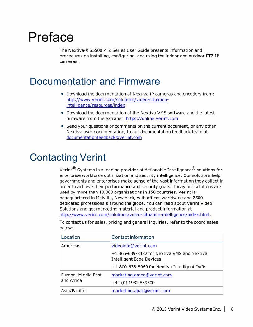
To contact us for sales, pricing and general inquiries, refer to the coordinatesbelow:
Location Contact Information
Americas [email protected]
+1 866-639-8482 for Nextiva VMS and NextivaIntelligent Edge Devices
+1-800-638-5969 for Nextiva Intelligent DVRs
Europe, Middle East,and Africa
+44 (0) 1932 839500
Asia/Pacific [email protected]
© 2013 Verint Video Systems Inc. 8
Location Contact Information
+ 852 2797 5678
Contacting Service and SupportTo request the latest versions of firmware and software or to download otherproduct-related documents, you need access to the Verint Video IntelligenceSolutions partner extranet. To register, go to https://online.verint.com.
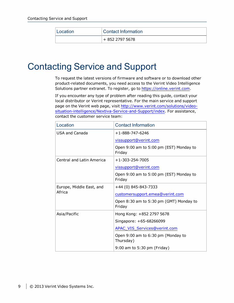
If you encounter any type of problem after reading this guide, contact yourlocal distributor or Verint representative. For the main service and supportpage on the Verint web page, visit http://www.verint.com/solutions/video-situation-intelligence/Nextiva-Service-and-Support/index. For assistance,contact the customer service team:
Location Contact Information
USA and Canada +1-888-747-6246
Open 9:00 am to 5:00 pm (EST) Monday toFriday
Central and Latin America +1-303-254-7005
Open 9:00 am to 5:00 pm (EST) Monday toFriday
Europe, Middle East, andAfrica
+44 (0) 845-843-7333
Open 8:30 am to 5:30 pm (GMT) Monday toFriday
Asia/Pacific Hong Kong: +852 2797 5678
Singapore: +65-68266099
Open 9:00 am to 6:30 pm (Monday toThursday)
9:00 am to 5:30 pm (Friday)
Contacting Service and Support
9 © 2013 Verint Video Systems Inc.
Summary of ChangesThis section lists technical updates and new material added to the NextivaUser Guide.
Revision 2 - October 2011This is the second edition of the Nextiva S5500 PTZ Series User Guide.
UpdatesAdded new procedure for installing the outdoor model using a pendent pipe.See "Installing the Nextiva S5500 PTZ Outdoor IP Cameras" (page 21).
Added a procedure for configuring the IP address using SConfigurator. See"Obtaining and Setting the IP Address" (page 1).
Revision 1 - May 2011This is the first edition of the Nextiva S5500 PTZ Series User Guide. The NextivaS5500 PTZ Series are compatible with Nextiva VMS 6.2 and higher.
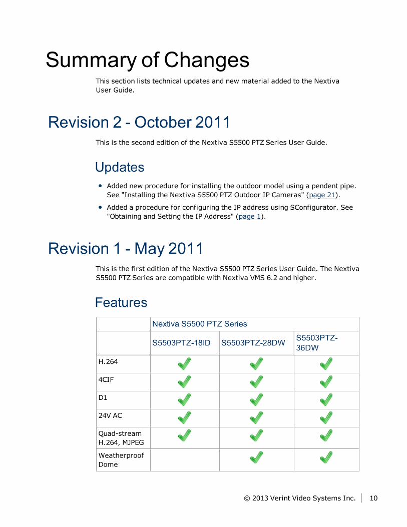
FeaturesNextiva S5500 PTZ Series
S5503PTZ-18ID S5503PTZ-28DW S5503PTZ-36DW
H.264
4CIF
D1
24V AC
Quad-streamH.264, MJPEG
WeatherproofDome
© 2013 Verint Video Systems Inc. 10
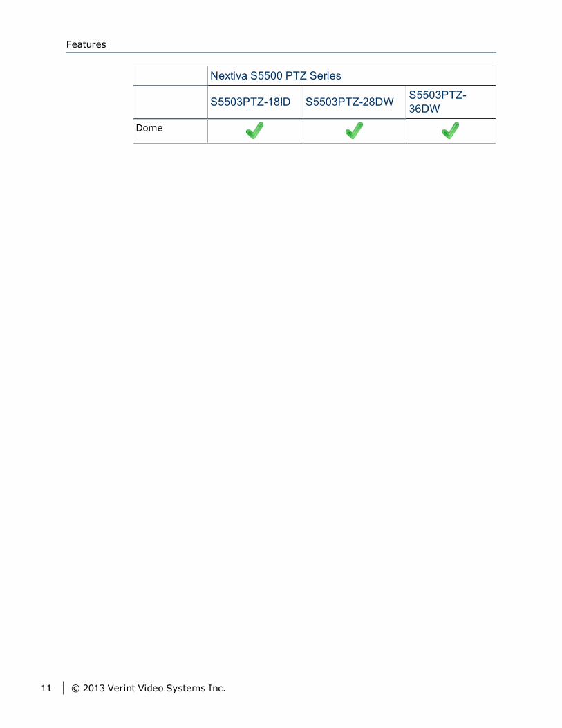
Nextiva S5500 PTZ Series
S5503PTZ-18ID S5503PTZ-28DW S5503PTZ-36DW
Dome
Features
11 © 2013 Verint Video Systems Inc.
The Nextiva S5500 Series series incorporates advanced Verint H.264 encodingtechnology with a high- performance PTZ platform. The results are ultra-efficient IP PTZ cameras with superior imagery, lower network bandwidthutilization, and full integration with the Nextiva video management portfolio.
The following topics are discussed:
Nextiva S5500 PTZ Series Overview 13
Hardware Overview 13
Frame Rate and Performance 18
Chapter 1Chapter 1: Nextiva S5500 Series Overview
Nextiva S5500 PTZ Series OverviewThe feature-rich Nextiva S5500 PTZ series includes 18x, 28x and 36x opticalzoom lens models for a variety of applications, as well as superior low light,day/night performance, and excellent dynamic range for challenging lightingconditions. Verint encoding technology delivers H.264 compression at up to D1resolution at 30 fps. The S5500 PTZ series also features full simultaneousanalog video out and control, for live recording and seamless operation as aretrofit or in a blended analog/IP configuration. This allows security personnelto operate the camera with zero control lag on-site, or to remotely control thePTZ with Nextiva Video Management Software or the Nextiva EdgeVR®network video recorder.
Hardware OverviewThe Nextiva S5500 PTZ series features programmable tilting, auto pan andalarm inputs. The Nextiva S5500 PTZ series feature 360° continuous pan andcan burst pan at 430°/sec for programmable stops. The cameras have animpressive 184° tilt range for viewing areas above their horizon. With up to 24three-dimensional programmable privacy masks, the Nextiva S5500 PTZ seriescombine high-performance with the recognition that not all areas the cameracan see should be seen by the operator – making the Nextiva S5500 PTZ seriesthe perfect urban orcity-center devices.
The Nextiva S5500 PTZ series are available in the following models:
Nextiva S5500 PTZ Indoor IP Cameras
S5503PTZ-18ID-P-S (Smoke bubble, PAL)
S5503PTZ-18ID-N-S (Smoke bubble, NTSC)
Nextiva S5500 PTZ Outdoor IP Cameras
S5503PTZ-28DW-P-C (Clear bubble, PAL)
S5503PTZ-28DW-N-C (Clear bubble, NTSC)
S5503PTZ-28DW-P-S (Smoke bubble, PAL)
S5503PTZ-28DW-N-S (Smoke bubble, NTSC)
S5503PTZ-36DW-P-S (Smoke bubble, PAL)
S5503PTZ-36DW-N-S (Smoke bubble, NTSC)
Nextiva S5500 PTZ Series Overview
13 © 2013 Verint Video Systems Inc.
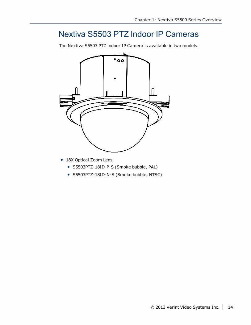
Nextiva S5503 PTZ Indoor IP CamerasThe Nextiva S5503 PTZ indoor IP Camera is available in two models.
18X Optical Zoom Lens
S5503PTZ-18ID-P-S (Smoke bubble, PAL)
S5503PTZ-18ID-N-S (Smoke bubble, NTSC)
Chapter 1: Nextiva S5500 Series Overview
© 2013 Verint Video Systems Inc. 14
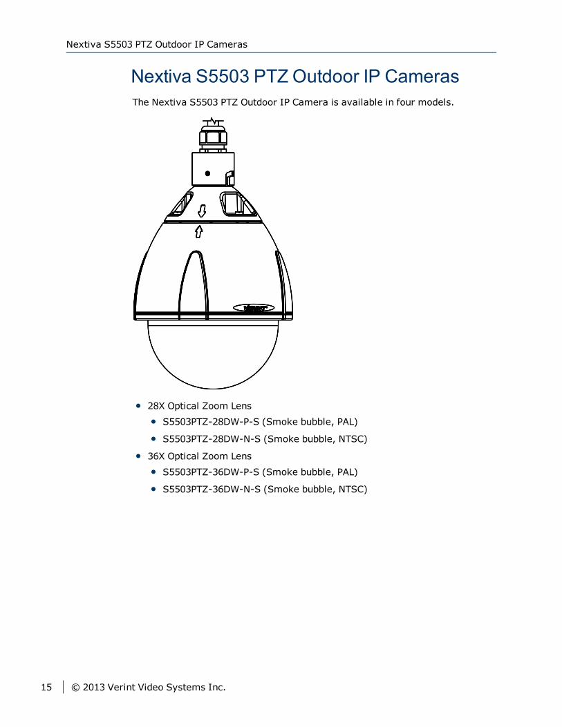
Nextiva S5503 PTZ Outdoor IP CamerasThe Nextiva S5503 PTZ Outdoor IP Camera is available in four models.
28X Optical Zoom Lens
S5503PTZ-28DW-P-S (Smoke bubble, PAL)
S5503PTZ-28DW-N-S (Smoke bubble, NTSC)
36X Optical Zoom Lens
S5503PTZ-36DW-P-S (Smoke bubble, PAL)
S5503PTZ-36DW-N-S (Smoke bubble, NTSC)
Nextiva S5503 PTZ Outdoor IP Cameras
15 © 2013 Verint Video Systems Inc.
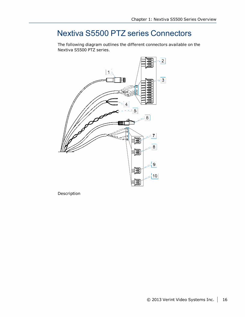
Nextiva S5500 PTZ series ConnectorsThe following diagram outlines the different connectors available on theNextiva S5500 PTZ series.
Description
Chapter 1: Nextiva S5500 Series Overview
© 2013 Verint Video Systems Inc. 16
1. BNC Connector (Video Out)
2. Preset Alarm Out:
Open (White)
Com (Light Blue)
Close (Pink)
3. Preset Alarm In:
In 1 (Brown)
In 2 (Red)
In 3 (Orange)
In 4 (Yellow)
In 5 (Green)
In 6 (Blue)
GND (Purple)
GND (Grey)
4. Power:
AC 24V (Black)
AC 24V (White)
GND (Green)
5. RS485:
+ (Orange)
- (White)
6. RJ-45 Connector
7. IP Alarm
In 1 (Green)
GND (Red)
8. IP Alarm
In 2 (Blue)
GND (Red)
9. IP Alarm Out
Out A (Yellow)
Out B (Brown)
10. IP Reset (Purple and Grey)
Nextiva S5500 PTZ series Connectors
17 © 2013 Verint Video Systems Inc.
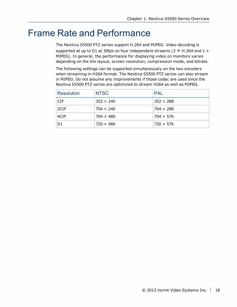
Frame Rate and PerformanceThe Nextiva S5500 PTZ series support H.264 and MJPEG. Video decoding issupported at up to D1 at 30fps on four independent streams (3× H.264 and 1 ×MJPEG). In general, the performance for displaying video on monitors variesdepending on the tile layout, screen resolution, compression mode, and bitrate.
The following settings can be supported simultaneously on the two encoderswhen streaming in H264 format. The Nextiva S5500 PTZ series can also streamin MJPEG. Do not assume any improvements if those codec are used since theNextiva S5500 PTZ series are optimized to stream H264 as well as MJPEG.
Resolution NTSC PAL
CIF 352 × 240 352 × 288
2CIF 704 × 240 704 × 288
4CIF 704 × 480 704 × 576
D1 720 × 480 720 × 576
Chapter 1: Nextiva S5500 Series Overview
© 2013 Verint Video Systems Inc. 18
From the indoor in-ceiling model, to the pendant-mount weatherproof outdoormodel, the Nextiva S5500 PTZ series come in a wide selection of types, housingand mounting options to meet an array of installation and operationalrequirements. The section describes the package contents of the Nextiva S5500PTZ series and how to install the outdoor and indoor models.
The following topics are discussed:
Package Contents 20
Installing the Nextiva S5500 PTZ Series 21
Powering the Nextiva S5500 PTZ Series 35
Connecting the Nextiva S5500 PTZ Series to the Network 35
Connecting the Nextiva S5500 PTZ Series to a Monitor 36
Chapter 2Chapter 2: Installing the Nextiva S5500
PTZ series
Package ContentsOne Preset Alarm In
One Preset Alarm Out
One IP Alarm In_1
One IP Alarm In_2
One IP Alarm Out
One IP Reset
One Power In (24VAC) Terminal
One LAN RJ-45 Adapter Female to Female
S5503PTZ-18ID
One S5503PTZ-18ID camera (S5503PTZ-18ID-P-S (Smoke bubble, PAL)or S5503PTZ-18ID-N-S (Smoke bubble, NTSC))
Nextiva S5500 PTZ Series Indoor Quick Installation Guide
S5503PTZ-28DW camera (S5503PTZ-28DW-P-S (Smoke bubble, PAL) orS5503PTZ-28DW-N-S (Smoke bubble, NTSC))
One Torx Key
One Hex (Allen) Key
One Set screw
Nextiva S5500 PTZ Series Outdoor Quick Installation Guide
S5503PTZ-36DW (S5503PTZ-36DW-P-S (Smoke bubble, PAL) or S5503PTZ-36DW-N-S (Smoke bubble, NTSC))
One Torx Key
One Hex (Allen) Key
One Set screw
Nextiva S5500 PTZ Series Outdoor Quick Installation Guide
Package Contents
20 © 2013 Verint Video Systems Inc.
Installing the Nextiva S5500 PTZ SeriesThis section explains how to mount the Nextiva S5500 PTZ series on a wall,pole or ceiling.
TipBefore installing the camera, look for a shooting area that best suits yourneeds.
Installing the Nextiva S5500 PTZ Outdoor IPCamerasThis section explains how to install the Nextiva S5503PTZ-28DW or S5503PTZ-36DW models.
NoteThe mounting hardware must be ordered separately.
► To install the Nextiva S5500 PTZ Outdoor IP Cameras on the wall:1. Remove the dome cover from the PTZ camera using the supplied
screwdriver.
2. Remove the lens cover and the foam protector.
3. Drill four pilot holes on the wall matching the mount holes on the plate.
4. Secure the plate to the wall.
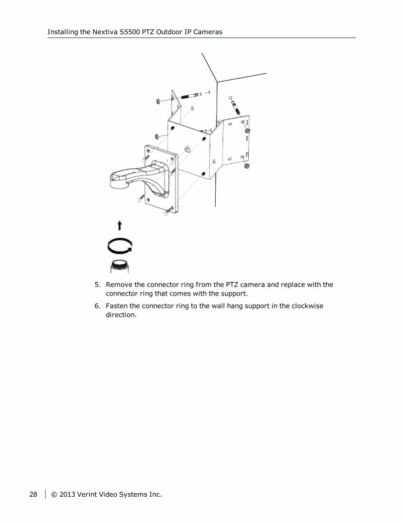
5. Remove the connector ring from the PTZ camera and replace with theconnector ring that comes with the support.
Chapter 2: Installing the Nextiva S5500 PTZ series
© 2013 Verint Video Systems Inc. 21
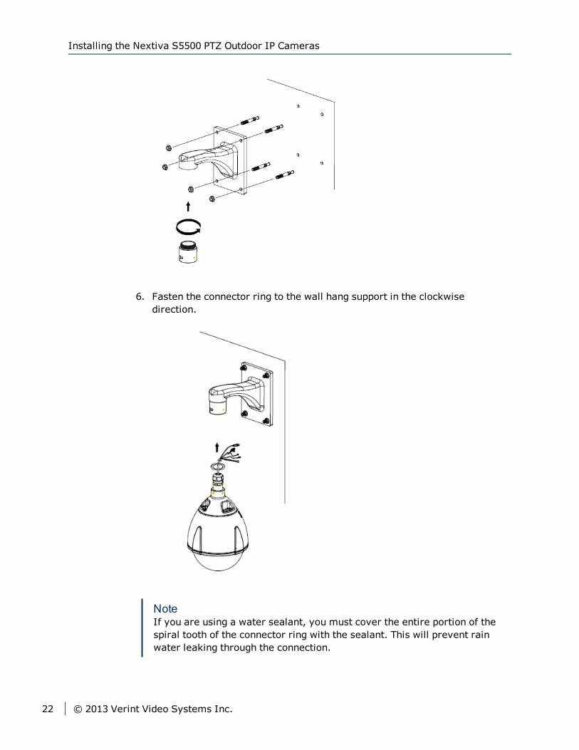
6. Fasten the connector ring to the wall hang support in the clockwisedirection.
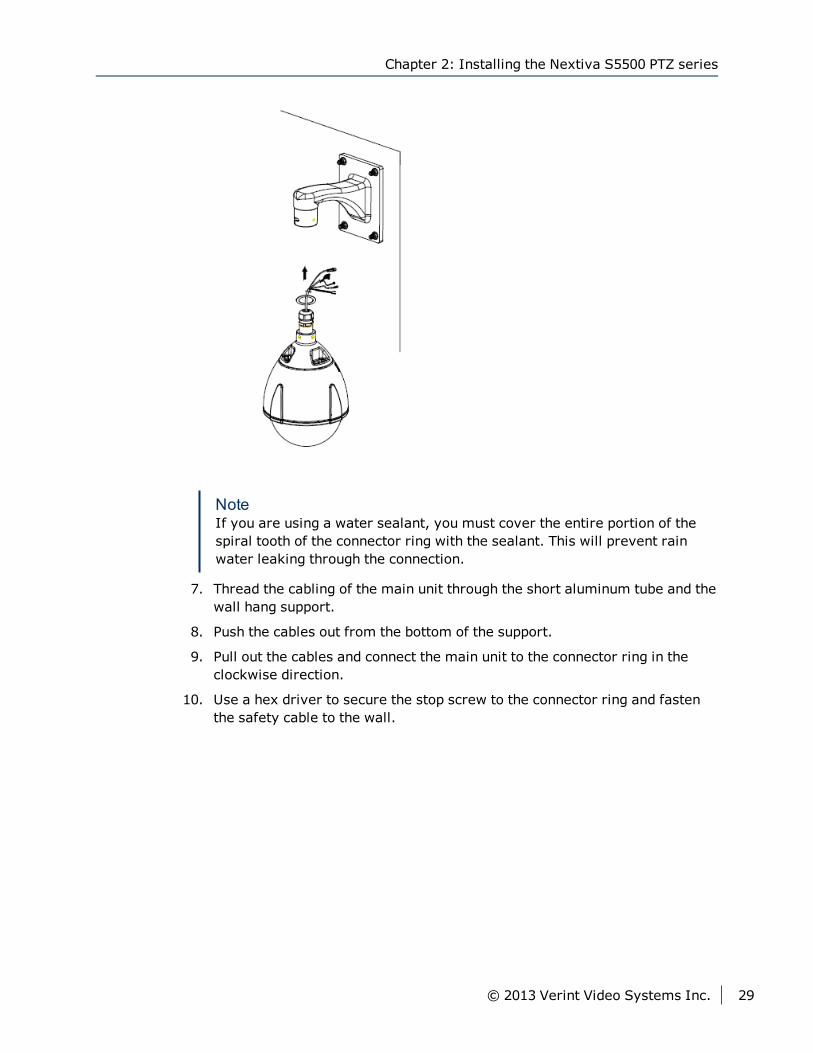
NoteIf you are using a water sealant, you must cover the entire portion of thespiral tooth of the connector ring with the sealant. This will prevent rainwater leaking through the connection.
Installing the Nextiva S5500 PTZ Outdoor IP Cameras
22 © 2013 Verint Video Systems Inc.
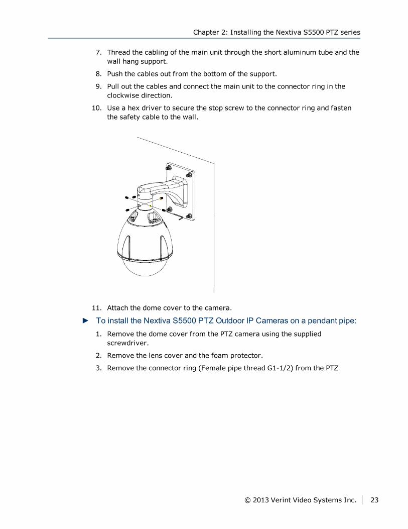
7. Thread the cabling of the main unit through the short aluminum tube and thewall hang support.
8. Push the cables out from the bottom of the support.
9. Pull out the cables and connect the main unit to the connector ring in theclockwise direction.
10. Use a hex driver to secure the stop screw to the connector ring and fastenthe safety cable to the wall.
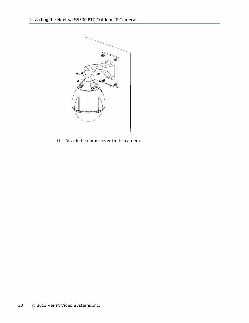
11. Attach the dome cover to the camera.
► To install the Nextiva S5500 PTZ Outdoor IP Cameras on a pendant pipe:1. Remove the dome cover from the PTZ camera using the supplied
screwdriver.
2. Remove the lens cover and the foam protector.
3. Remove the connector ring (Female pipe thread G1-1/2) from the PTZ
Chapter 2: Installing the Nextiva S5500 PTZ series
© 2013 Verint Video Systems Inc. 23
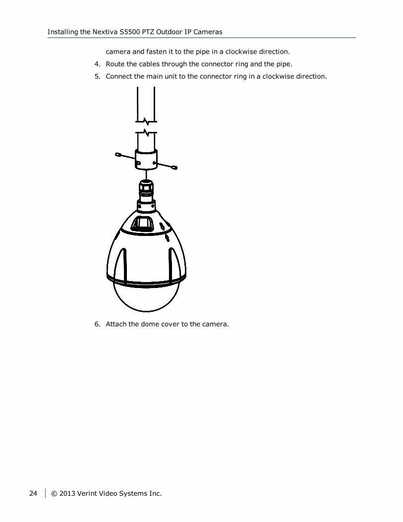
camera and fasten it to the pipe in a clockwise direction.
4. Route the cables through the connector ring and the pipe.
5. Connect the main unit to the connector ring in a clockwise direction.
6. Attach the dome cover to the camera.
Installing the Nextiva S5500 PTZ Outdoor IP Cameras
24 © 2013 Verint Video Systems Inc.
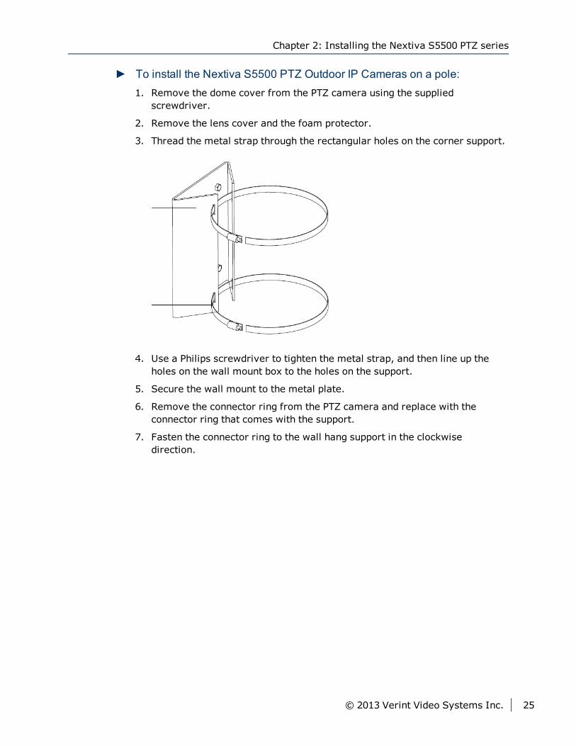
► To install the Nextiva S5500 PTZ Outdoor IP Cameras on a pole:1. Remove the dome cover from the PTZ camera using the supplied
screwdriver.
2. Remove the lens cover and the foam protector.
3. Thread the metal strap through the rectangular holes on the corner support.
4. Use a Philips screwdriver to tighten the metal strap, and then line up theholes on the wall mount box to the holes on the support.
5. Secure the wall mount to the metal plate.
6. Remove the connector ring from the PTZ camera and replace with theconnector ring that comes with the support.
7. Fasten the connector ring to the wall hang support in the clockwisedirection.
Chapter 2: Installing the Nextiva S5500 PTZ series
© 2013 Verint Video Systems Inc. 25
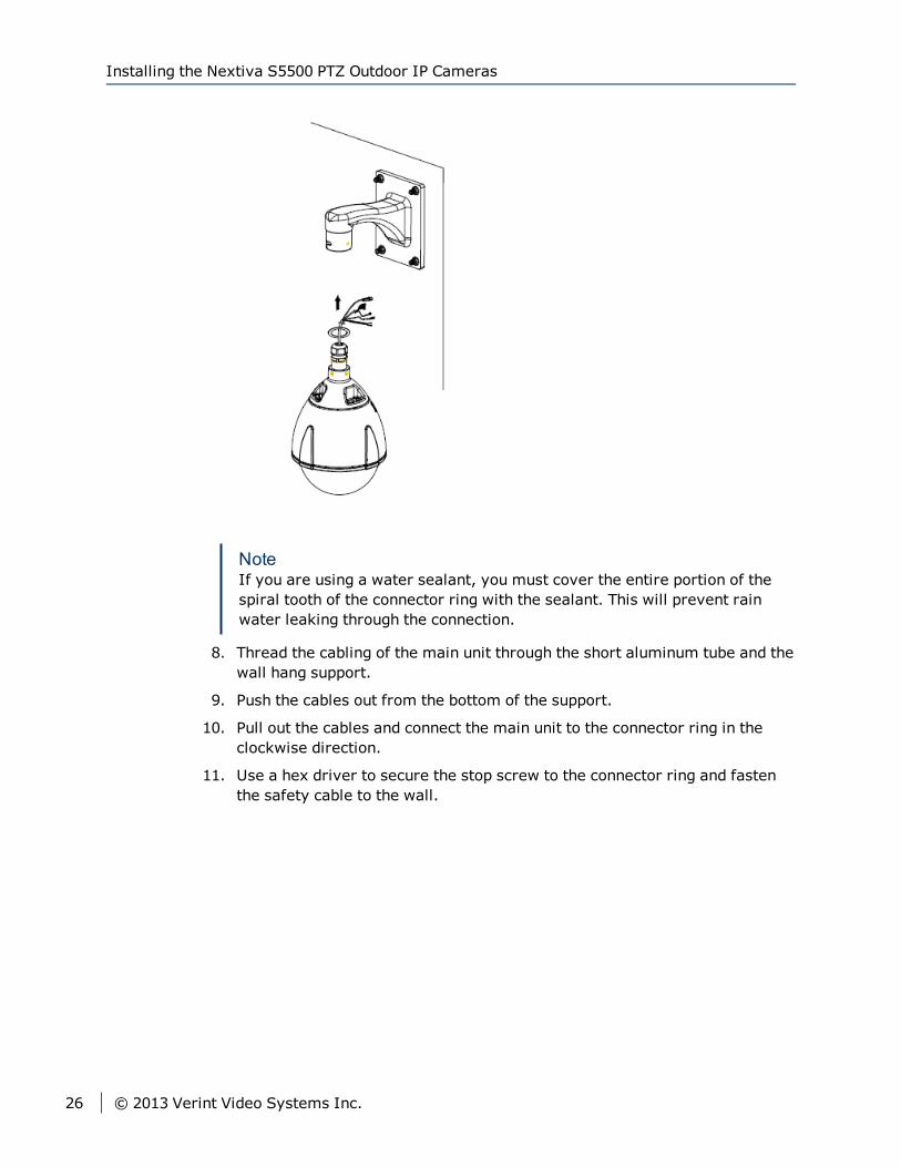
NoteIf you are using a water sealant, you must cover the entire portion of thespiral tooth of the connector ring with the sealant. This will prevent rainwater leaking through the connection.
8. Thread the cabling of the main unit through the short aluminum tube and thewall hang support.
9. Push the cables out from the bottom of the support.
10. Pull out the cables and connect the main unit to the connector ring in theclockwise direction.
11. Use a hex driver to secure the stop screw to the connector ring and fastenthe safety cable to the wall.
Installing the Nextiva S5500 PTZ Outdoor IP Cameras
26 © 2013 Verint Video Systems Inc.
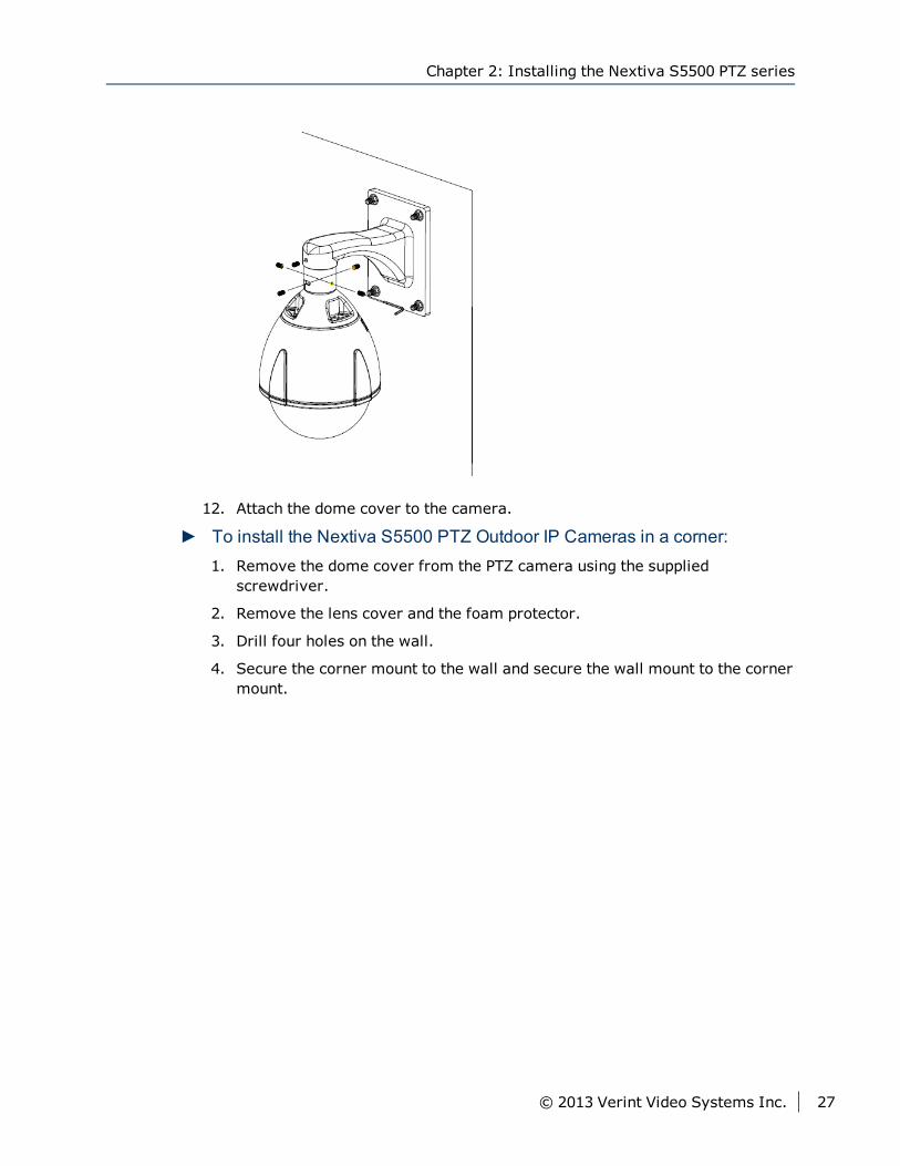
12. Attach the dome cover to the camera.
► To install the Nextiva S5500 PTZ Outdoor IP Cameras in a corner:1. Remove the dome cover from the PTZ camera using the supplied
screwdriver.
2. Remove the lens cover and the foam protector.
3. Drill four holes on the wall.
4. Secure the corner mount to the wall and secure the wall mount to the cornermount.
Chapter 2: Installing the Nextiva S5500 PTZ series
© 2013 Verint Video Systems Inc. 27
5. Remove the connector ring from the PTZ camera and replace with theconnector ring that comes with the support.
6. Fasten the connector ring to the wall hang support in the clockwisedirection.
Installing the Nextiva S5500 PTZ Outdoor IP Cameras
28 © 2013 Verint Video Systems Inc.
NoteIf you are using a water sealant, you must cover the entire portion of thespiral tooth of the connector ring with the sealant. This will prevent rainwater leaking through the connection.
7. Thread the cabling of the main unit through the short aluminum tube and thewall hang support.
8. Push the cables out from the bottom of the support.
9. Pull out the cables and connect the main unit to the connector ring in theclockwise direction.
10. Use a hex driver to secure the stop screw to the connector ring and fastenthe safety cable to the wall.
Chapter 2: Installing the Nextiva S5500 PTZ series
© 2013 Verint Video Systems Inc. 29
11. Attach the dome cover to the camera.
Installing the Nextiva S5500 PTZ Outdoor IP Cameras
30 © 2013 Verint Video Systems Inc.
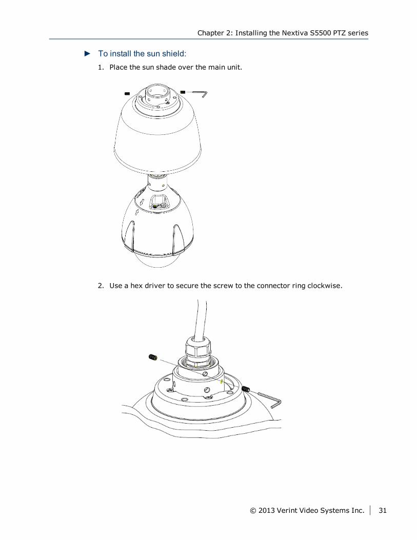
► To install the sun shield:1. Place the sun shade over the main unit.
2. Use a hex driver to secure the screw to the connector ring clockwise.
Chapter 2: Installing the Nextiva S5500 PTZ series
© 2013 Verint Video Systems Inc. 31
Installing the Nextiva S5500 PTZ Indoor IPCameraThis section explains how to install the Nextiva S5503PTZ-18ID models.
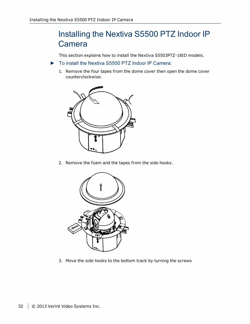
► To install the Nextiva S5500 PTZ Indoor IP Camera:1. Remove the four tapes from the dome cover then open the dome cover
counterclockwise.
2. Remove the foam and the tapes from the side hooks.
3. Move the side hooks to the bottom track by turning the screws
Installing the Nextiva S5500 PTZ Indoor IP Camera
32 © 2013 Verint Video Systems Inc.
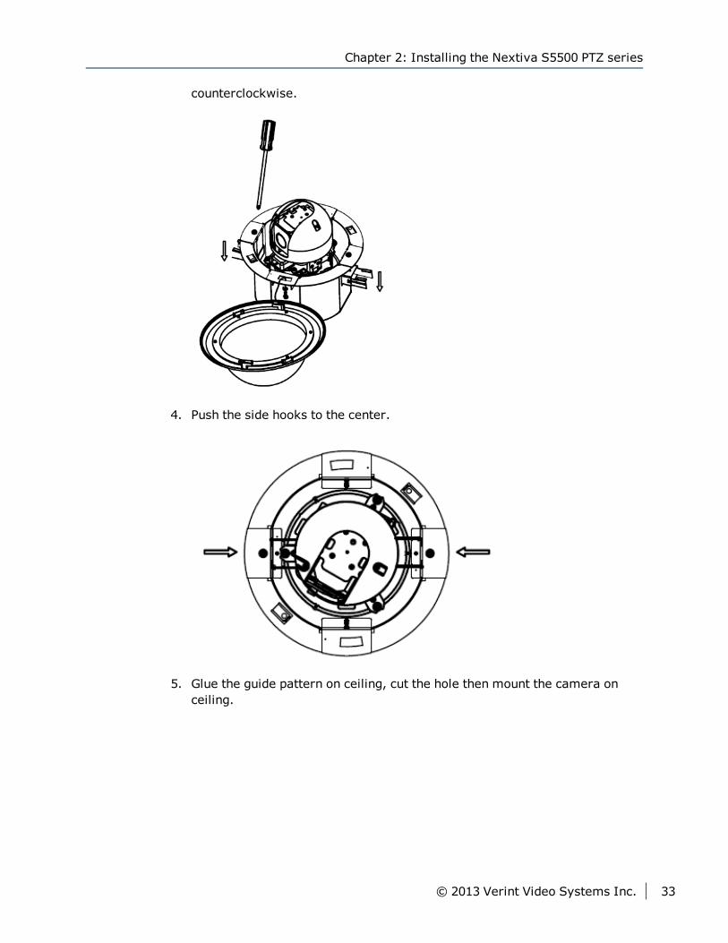
counterclockwise.
4. Push the side hooks to the center.
5. Glue the guide pattern on ceiling, cut the hole then mount the camera onceiling.
Chapter 2: Installing the Nextiva S5500 PTZ series
© 2013 Verint Video Systems Inc. 33
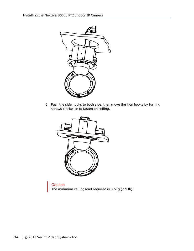
6. Push the side hooks to both side, then move the iron hooks by turningscrews clockwise to fasten on ceiling.
CautionThe minimum ceiling load required is 3.6Kg (7.9 lb).
Installing the Nextiva S5500 PTZ Indoor IP Camera
34 © 2013 Verint Video Systems Inc.
Powering the Nextiva S5500 PTZ SeriesUse the following procedure to power the Nextiva S5500 PTZ Series using a 24VAC for power.
NoteThe Nextiva S5503PTZ-18ID requires 18W and the Nextiva S5503PTZ-28DWand S5503PTZ-36DW requires 46W (With a high-speed dome camera: 20W,with a heater: 26W)
► To power the Nextiva S5500 PTZ Series using a 24V AC powersupply:
1. Connect the wires (Black and White) from the camera to the terminal block.
2. Connect the ground wire (Green) to a proper electrical ground.
3. Connect the wires from the power supply to the terminal block.
4. Plug the power supply cable to the power outlet.
Connecting the Nextiva S5500 PTZ Seriesto the Network
Use the following procedure to connect the Nextiva S5500 PTZ Series to thenetwork.
► To connect the Nextiva S5500 PTZ Series to the network:1. Connect the RJ45 male connector to the RJ45 coupler.
2. Connect an ethernet cable into the RJ45 coupler.
Chapter 2: Installing the Nextiva S5500 PTZ series
© 2013 Verint Video Systems Inc. 35
Connecting the Nextiva S5500 PTZ Seriesto a Monitor
Use the following procedure to connect the Nextiva S5500 PTZ Series to amonitor.
► To connect the Nextiva S5500 PTZ Series to a monitor:1. Connect the video out connector from the camera to the BNC connector
from the monitor.
Connecting the Nextiva S5500 PTZ Series to a Monitor
36 © 2013 Verint Video Systems Inc.
Once you have connected the Nextiva S5500 PTZ Series to the network, you canbegin configuring the IP camera to ensure that it can communicate with theattached devices and with a video management software over the network.
The following topics are discussed:
Device Configuration 38
IP Address Configuration 39
Setting the Video Standard 46
Video Profile 50
Setting the SNMP Properties 58
Viewing Live Video 61
Configuring PTZ Address 64
Chapter 3Chapter 3: Configuring the IP Settings
Device ConfigurationOnce you have connected all the equipment to the device, you can beginconfiguring the device to ensure that it can communicate with the attacheddevices and with a video management software over the network. In order toconfigure the device, you first need to obtain the IP address usingSConfigurator.
1. Using SConfigurator: SConfigurator is a PC-based administration tool thatyou can use over any TCP/IP network. You use SConfigurator to:
Configure Nextiva edge devices
Add security in your system
Get information on the devices connected on the network
Connect edge devices together
Update the firmware of the devices
Align the antennas of wireless devices
Manage licenses
Using a Video Management Software: You can use any videomanagement software to configure the device.
2. Using a Video Management Software: You can use any video managementsoftware to configure the device.
CautionAny changes made using the video management software will overridethe changes made using SConfigurator or the Web Interface.
3. Using the Web Interface: The Nextiva S5500 PTZ Series have a self-contained web server allowing you to connect directly to it using a webbrowser. The Web Interface is a browser-based tool that allows you toconfigure the Nextiva S5500 PTZ Series. For complete information on theWeb Interface, refer to the Web Interface User Guide.
NoteThe default username and password for the Web Interface is admin. Werecommend that you change the default password for the Edge device to amore secure password.
Device Configuration
38 © 2013 Verint Video Systems Inc.
IP Address ConfigurationBy default, all S1800e series devices are Dynamic Host Configuration Protocol(DHCP ) enabled. If you have a DHCP server, the device will automaticallyobtain a valid IP configuration. If the DHCP configuration fails, the deviceassigns itself a temporary IP address based on the Automatic Private IPAddressing (APIPA ) addressing format.
NoteIf you plan on using the S1800e series devices with the Nextiva videomanagement software, you need to disable the DHCP setting and manually setan IP address for the device.
The APIPA scheme, available on the Windows operating systems, allows adevice to assign itself a temporary IP address until it receives a completenetwork configuration, either manually or from a DHCP server.
A device in APIPA mode does not reside on the same subnet as the otherdevices on the IP network. Therefore, it may not be able to view or be visibleby the other devices. All Nextiva edge devices use the following temporaryAPIPA configuration:
IP address: 169.254.X.Y (where X and Y are based on the last two octets ofthe MAC address of the device)
Subnet mask: 255.255.0.0
Gateway: 169.254.*.*
Chapter 3: Configuring the IP Settings
© 2013 Verint Video Systems Inc. 39
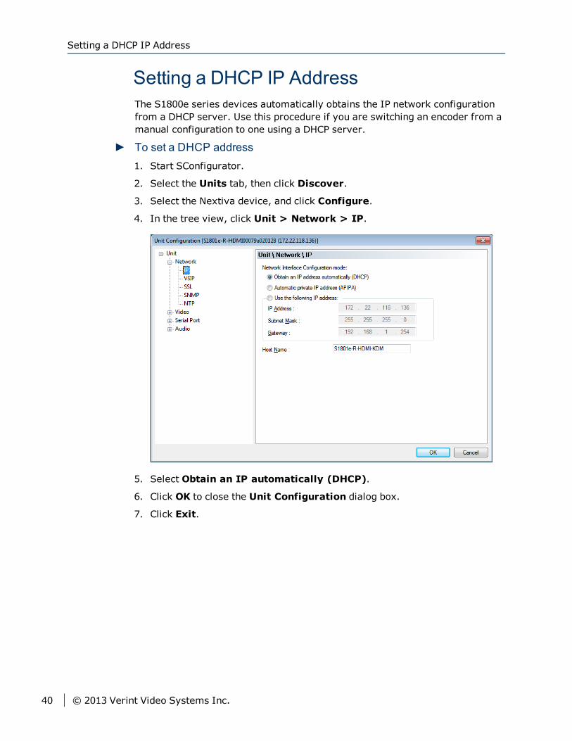
Setting a DHCP IP AddressThe S1800e series devices automatically obtains the IP network configurationfrom a DHCP server. Use this procedure if you are switching an encoder from amanual configuration to one using a DHCP server.
► To set a DHCP address1. Start SConfigurator.
2. Select the Units tab, then click Discover.
3. Select the Nextiva device, and click Configure.
4. In the tree view, click Unit > Network > IP.
5. Select Obtain an IP automatically (DHCP).
6. Click OK to close the Unit Configuration dialog box.
7. Click Exit.
Setting a DHCP IP Address
40 © 2013 Verint Video Systems Inc.
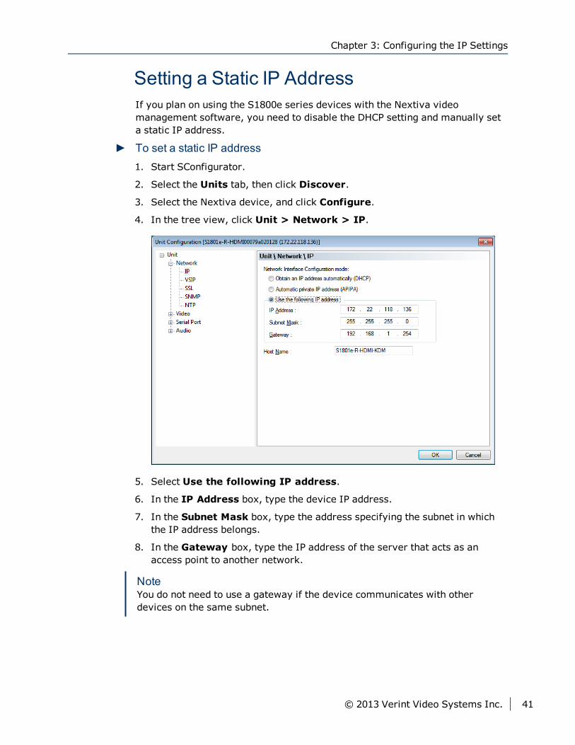
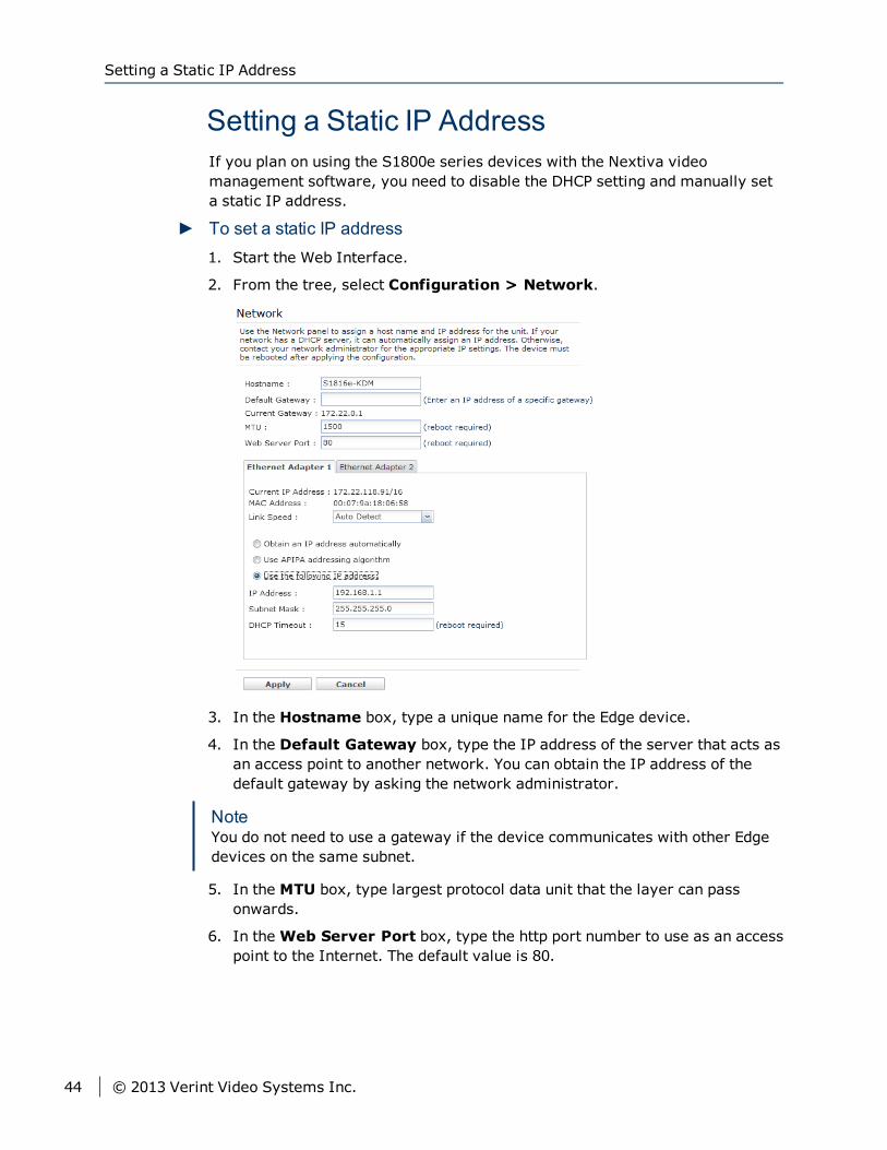
Setting a Static IP AddressIf you plan on using the S1800e series devices with the Nextiva videomanagement software, you need to disable the DHCP setting and manually seta static IP address.
► To set a static IP address1. Start SConfigurator.
2. Select the Units tab, then click Discover.
3. Select the Nextiva device, and click Configure.
4. In the tree view, click Unit > Network > IP.
5. Select Use the following IP address.
6. In the IP Address box, type the device IP address.
7. In the Subnet Mask box, type the address specifying the subnet in whichthe IP address belongs.
8. In the Gateway box, type the IP address of the server that acts as anaccess point to another network.
NoteYou do not need to use a gateway if the device communicates with otherdevices on the same subnet.
Chapter 3: Configuring the IP Settings
© 2013 Verint Video Systems Inc. 41
9. In the Host Name box, type a unique name for the device.
10. Click OK to close the Unit Configuration dialog box.
11. Click Exit.
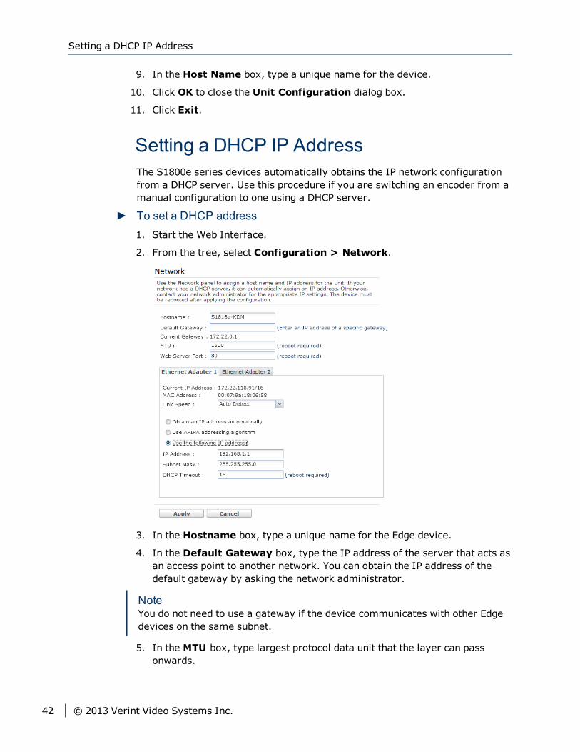
Setting a DHCP IP AddressThe S1800e series devices automatically obtains the IP network configurationfrom a DHCP server. Use this procedure if you are switching an encoder from amanual configuration to one using a DHCP server.
► To set a DHCP address1. Start the Web Interface.
2. From the tree, select Configuration > Network.
3. In the Hostname box, type a unique name for the Edge device.
4. In the Default Gateway box, type the IP address of the server that acts asan access point to another network. You can obtain the IP address of thedefault gateway by asking the network administrator.
NoteYou do not need to use a gateway if the device communicates with other Edgedevices on the same subnet.
5. In the MTU box, type largest protocol data unit that the layer can passonwards.
Setting a DHCP IP Address
42 © 2013 Verint Video Systems Inc.
6. In theWeb Server Port box, type the http port number to use as an accesspoint to the internet. The default value is 80.
7. In the Ethernet Adapter 1 tab:
a. In the Link Speed list, select the speed and mode of the network:
Auto detect: The unit will automatically detect the network speedand mode.
1 Gbps full duplex: The unit sends and receives 1 Gbps of data inboth directions at the same time.
1 Gbps half duplex: The unit sends and receives 1 Gbps of data inboth directions, but not at the same time.
100 Mbps full duplex: The unit sends and receives 100 Mbps ofdata in both directions at the same time.
100 Mbps half duplex: The unit sends and receives 100 Mbps ofdata in both directions, but not at the same time.
10 Mbps full duplex: The unit sends and receives 10 Mbps of datain both directions at the same time.
10 Mbps half duplex: The unit sends and receives 10 Mbps of datain both directions, but not at the same time.
NoteIf you are unsure of the network settings, select Auto detect toautomatically detect the speed and mode of the network. You can alsocontact the network administrator to provide you with the correctsettings.
b. Click Obtain an IP address automatically.
c. In the DHCP Timeout box, type the number of seconds to wait for aresponse from a DHCP server before using the APIPA address.
8. Click Apply.
NoteThe Ethernet Adapter 2 tab corresponds to LAN 2 on the S1808e, S1808e-A,S1816e, S1816e-A and S816e-SP encoders, and is used by support fordebugging purposes. The S1816e-SR model does not have a second ethernetport.
The default IP address of LAN 2 is set to 172.29.204.254 with subnet mask255.255.255.252. Any computer connecting to the S1800e multiport encodersmust use the following IP address 172.29.204.253.
Chapter 3: Configuring the IP Settings
© 2013 Verint Video Systems Inc. 43
Setting a Static IP AddressIf you plan on using the S1800e series devices with the Nextiva videomanagement software, you need to disable the DHCP setting and manually seta static IP address.
► To set a static IP address1. Start the Web Interface.
2. From the tree, select Configuration > Network.
3. In the Hostname box, type a unique name for the Edge device.
4. In the Default Gateway box, type the IP address of the server that acts asan access point to another network. You can obtain the IP address of thedefault gateway by asking the network administrator.
NoteYou do not need to use a gateway if the device communicates with other Edgedevices on the same subnet.
5. In the MTU box, type largest protocol data unit that the layer can passonwards.
6. In theWeb Server Port box, type the http port number to use as an accesspoint to the Internet. The default value is 80.
Setting a Static IP Address
44 © 2013 Verint Video Systems Inc.
7. In the Ethernet Adapter 1 tab:
a. In the Link Speed list, select the speed and mode of the network:
Auto detect: The unit will automatically detect the network speedand mode.
1 Gbps full duplex: The unit sends and receives 1 Gbps of data inboth directions at the same time.
1 Gbps half duplex: The unit sends and receives 1 Gbps of data inboth directions, but not at the same time.
100 Mbps full duplex: The unit sends and receives 100 Mbps ofdata in both directions at the same time.
100 Mbps half duplex: The unit sends and receives 100 Mbps ofdata in both directions, but not at the same time.
10 Mbps full duplex: The unit sends and receives 10 Mbps of datain both directions at the same time.
10 Mbps half duplex: The unit sends and receives 10 Mbps of datain both directions, but not at the same time.
NoteIf you are unsure of the network settings, select Auto detect toautomatically detect the speed and mode of the network. You can alsocontact the network administrator to provide you with the correctsettings.
b. Click Use the following IP Address.
c. In the IP Address box, type the device IP address.
d. In the Subnet Mask box, type the address specifying the subnet inwhich the IP address belongs.
e. In the Gateway box, type the IP address of the server that acts as anaccess point to another network.
NoteYou do not need to use a gateway if the device communicates with otherdevices on the same subnet.
8. Click Apply.
Chapter 3: Configuring the IP Settings
© 2013 Verint Video Systems Inc. 45
NoteThe Ethernet Adapter 2 tab corresponds to LAN 2 on the S1808e, S1808e-A,S1816e, S1816e-A and S816e-SP encoders, and is used by support fordebugging purposes. The S1816e-SR model does not have a second Ethernetport.
The default IP address of LAN 2 is set to 172.29.204.254 with subnet mask255.255.255.252. Any computer connecting to the S1800e multiport encodersmust use the following IP address 172.29.204.253.
Setting the Video StandardThe S1800e series device can run in one of two video standards (NTSC or PAL)and you can use different standards when deploying the devices across multiplesites. The two video standards settings are:
National Television Standards Committee (NTSC) is the standard that is used inmost of the Americas, a number of South American countries, and some Asiancountries, including Japan. NTSC uses the format of 525 picture lines and a60Hz lighting frequency.
Phase Alternation by Line (PAL) is the standard in the United Kingdom, much ofWestern Europe, several South American countries, some Middle East andAsian countries, several African countries, Australia, New Zealand, and otherPacific island countries. PAL uses the format of 625 picture lines and a 50Hzlighting frequency.
CautionYou should change the video profile settings using a video managementsoftware.
Setting the Video Standard
46 © 2013 Verint Video Systems Inc.
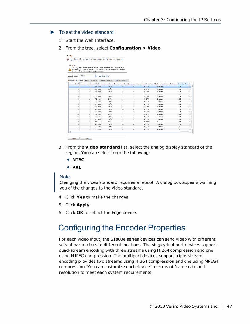
► To set the video standard1. Start the Web Interface.
2. From the tree, select Configuration > Video.
3. From the Video standard list, select the analog display standard of theregion. You can select from the following:
NTSC
PAL
NoteChanging the video standard requires a reboot. A dialog box appears warningyou of the changes to the video standard.
4. Click Yes to make the changes.
5. Click Apply.
6. Click OK to reboot the Edge device.
Configuring the Encoder PropertiesFor each video input, the S1800e series devices can send video with differentsets of parameters to different locations. The single/dual port devices supportquad-stream encoding with three streams using H.264 compression and oneusing MJPEG compression. The multiport devices support triple-streamencoding provides two streams using H.264 compression and one using MPEG4compression. You can customize each device in terms of frame rate andresolution to meet each system requirements.
Chapter 3: Configuring the IP Settings
© 2013 Verint Video Systems Inc. 47
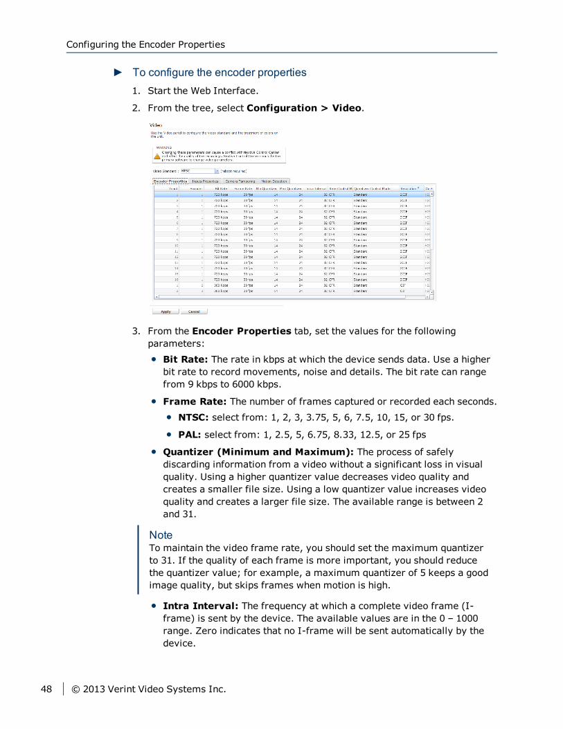
► To configure the encoder properties1. Start the Web Interface.
2. From the tree, select Configuration > Video.
3. From the Encoder Properties tab, set the values for the followingparameters:
Bit Rate: The rate in kbps at which the device sends data. Use a higherbit rate to record movements, noise and details. The bit rate can rangefrom 9 kbps to 6000 kbps.
Frame Rate: The number of frames captured or recorded each seconds.
NTSC: select from: 1, 2, 3, 3.75, 5, 6, 7.5, 10, 15, or 30 fps.
PAL: select from: 1, 2.5, 5, 6.75, 8.33, 12.5, or 25 fps
Quantizer (Minimum and Maximum): The process of safelydiscarding information from a video without a significant loss in visualquality. Using a higher quantizer value decreases video quality andcreates a smaller file size. Using a low quantizer value increases videoquality and creates a larger file size. The available range is between 2and 31.
NoteTo maintain the video frame rate, you should set the maximum quantizerto 31. If the quality of each frame is more important, you should reducethe quantizer value; for example, a maximum quantizer of 5 keeps a goodimage quality, but skips frames when motion is high.
Intra Interval: The frequency at which a complete video frame (I-frame) is sent by the device. The available values are in the 0 – 1000range. Zero indicates that no I-frame will be sent automatically by thedevice.
Configuring the Encoder Properties
48 © 2013 Verint Video Systems Inc.
Rate Control Mode: The mode controlling the bit rate variation. Theavailable modes are:
Constant Bit Rate (CBR): This mode is the most effective tomaintain the target bit rate. Video quality may suffer (frames may beskipped) and the frame rate may decrease. This mode should be usedwhen transmitting video over networks that have very limitedbandwidths, and with an intra interval value of 0 (default).
Constant Frame Rate (CFR): This mode maintains the targetframe rate. Video quality may suffer and the bit rate may exceed thetarget value.
Quantizer Control Mode:
Standard:
High on Motion Area:
Resolution: The total number of lines (width × height) in the videoimage. The greater the number of lines produces a more detailed,clearer and sharper image, but requires more bandwidth and storage.The following resolutions are available:
CIF: NTSC (352 × 240) and PAL (352 × 288)
2CIF: NTSC (704 × 240) and PAL (704 × 288)
4CIF: NTSC (704 × 480) and PAL (704 × 576)
D1: NTSC (720 × 486) and PAL (720 × 576)
Compression Mode: This parameter cannot be changed. Thecompression mode column displays the method of encoding currentlybeing used on the Edge device. For the multiport devices, encoders 1 and2 are set to H.264 and encoder 3 is set to MPEG4. For the single/dualdevices, encoders 1, 2 and 3 are set to H.264 and encoder 4 is set toMJPEG.
NoteFor devices running analytics and the S1816e-SP and S1816e-SR models running in single or legacy mode, only two streams areavailable. In this case, Encoder 1 is set to H.264 and Encoder 2 is set toMPEG4.
4. Click Apply.
5. Click OK.
Chapter 3: Configuring the IP Settings
© 2013 Verint Video Systems Inc. 49
Video ProfileVideo Profiles define both the quality of the video images and the storage andbandwidth requirements of the video files. All Video Profiles include at least thefollowing settings: frame rate, resolution, and bit rate. For each video input,you can configure the image parameters. With each video input, the S1800eseries devices supports up to quad-stream encoding (triple-stream encoding onthe multiport devices and quad-stream encoding on the single/dual portdevices). Encoding the video inputs provides multiple live-view streams usingdifferent sets of parameters providing high or low quality video for analysis anda single recording stream using H.264 video compression providing high qualityvideo at a substantially lower bit rates than previous standards.
NoteNextiva video management software currently supports a maximum of twostreams and provide four video profiles for the S1800e series devices. Formore information configuring video profiles, refer to the NextivaVMS Administrator Guide.
Configuring the Encoder PropertiesFor each video input, the S1800e series devices can send video with differentsets of parameters to different locations. The single/dual port devices supportquad-stream encoding with three streams using H.264 compression and oneusing MJPEG compression. The multiport devices support triple-streamencoding provides two streams using H.264 compression and one using MPEG4compression. You can customize each device in terms of frame rate andresolution to meet each system requirements.
Video Profile
50 © 2013 Verint Video Systems Inc.
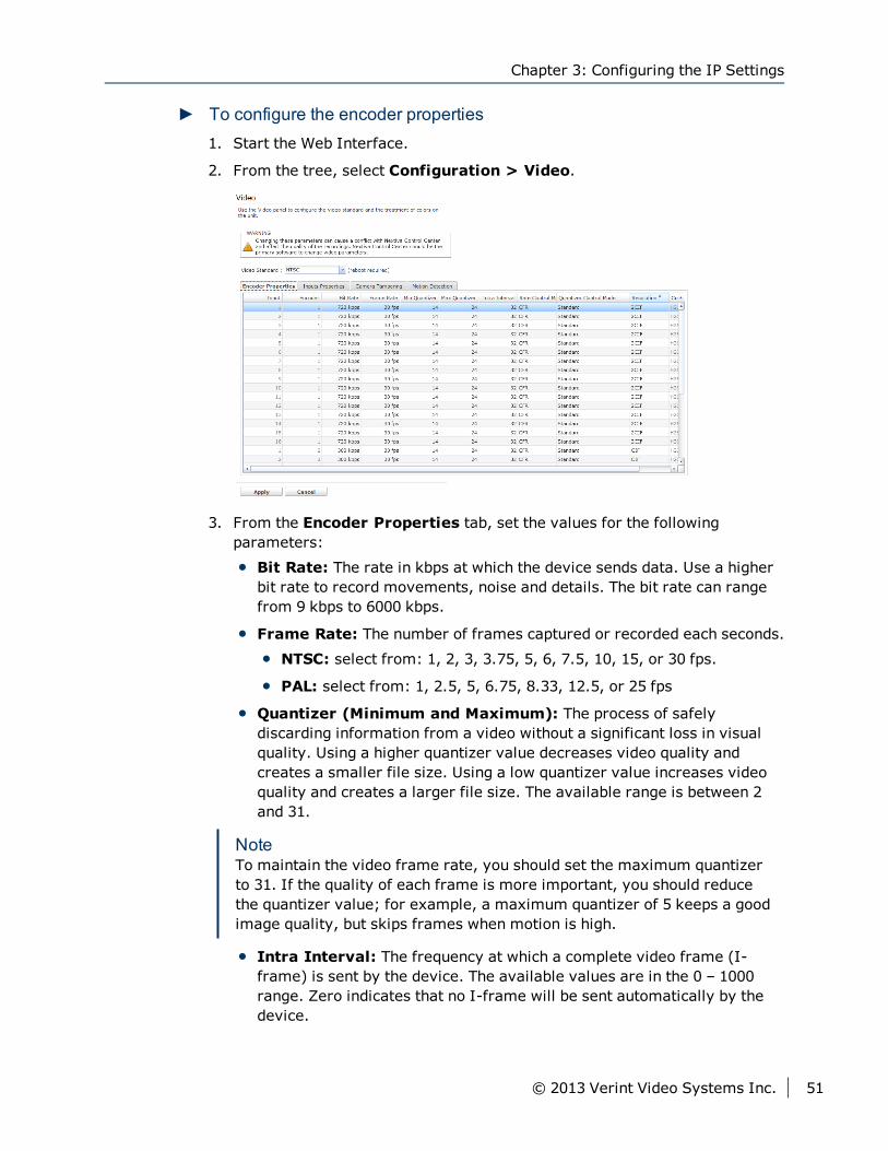
► To configure the encoder properties1. Start the Web Interface.
2. From the tree, select Configuration > Video.
3. From the Encoder Properties tab, set the values for the followingparameters:
Bit Rate: The rate in kbps at which the device sends data. Use a higherbit rate to record movements, noise and details. The bit rate can rangefrom 9 kbps to 6000 kbps.
Frame Rate: The number of frames captured or recorded each seconds.
NTSC: select from: 1, 2, 3, 3.75, 5, 6, 7.5, 10, 15, or 30 fps.
PAL: select from: 1, 2.5, 5, 6.75, 8.33, 12.5, or 25 fps
Quantizer (Minimum and Maximum): The process of safelydiscarding information from a video without a significant loss in visualquality. Using a higher quantizer value decreases video quality andcreates a smaller file size. Using a low quantizer value increases videoquality and creates a larger file size. The available range is between 2and 31.
NoteTo maintain the video frame rate, you should set the maximum quantizerto 31. If the quality of each frame is more important, you should reducethe quantizer value; for example, a maximum quantizer of 5 keeps a goodimage quality, but skips frames when motion is high.
Intra Interval: The frequency at which a complete video frame (I-frame) is sent by the device. The available values are in the 0 – 1000range. Zero indicates that no I-frame will be sent automatically by thedevice.
Chapter 3: Configuring the IP Settings
© 2013 Verint Video Systems Inc. 51
Rate Control Mode: The mode controlling the bit rate variation. Theavailable modes are:
Constant Bit Rate (CBR): This mode is the most effective tomaintain the target bit rate. Video quality may suffer (frames may beskipped) and the frame rate may decrease. This mode should be usedwhen transmitting video over networks that have very limitedbandwidths, and with an intra interval value of 0 (default).
Constant Frame Rate (CFR): This mode maintains the targetframe rate. Video quality may suffer and the bit rate may exceed thetarget value.
Quantizer Control Mode:
Standard:
High on Motion Area:
Resolution: The total number of lines (width × height) in the videoimage. The greater the number of lines produces a more detailed,clearer and sharper image, but requires more bandwidth and storage.The following resolutions are available:
CIF: NTSC (352 × 240) and PAL (352 × 288)
2CIF: NTSC (704 × 240) and PAL (704 × 288)
4CIF: NTSC (704 × 480) and PAL (704 × 576)
D1: NTSC (720 × 486) and PAL (720 × 576)
Compression Mode: This parameter cannot be changed. Thecompression mode column displays the method of encoding currentlybeing used on the Edge device. For the multiport devices, encoders 1 and2 are set to H.264 and encoder 3 is set to MPEG4. For the single/dualdevices, encoders 1, 2 and 3 are set to H.264 and encoder 4 is set toMJPEG.
NoteFor devices running analytics and the S1816e-SP and S1816e-SR models running in single or legacy mode, only two streams areavailable. In this case, Encoder 1 is set to H.264 and Encoder 2 is set toMPEG4.
4. Click Apply.
5. Click OK.
Configuring the Encoder Properties
52 © 2013 Verint Video Systems Inc.
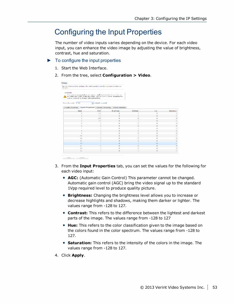
Configuring the Input PropertiesThe number of video inputs varies depending on the device. For each videoinput, you can enhance the video image by adjusting the value of brightness,contrast, hue and saturation.
► To configure the input properties1. Start the Web Interface.
2. From the tree, select Configuration > Video.
3. From the Input Properties tab, you can set the values for the following foreach video input:
AGC: (Automatic Gain Control) This parameter cannot be changed.Automatic gain control (AGC) bring the video signal up to the standard1Vpp required level to produce quality picture.
Brightness: Changing the brightness level allows you to increase ordecrease highlights and shadows, making them darker or lighter. Thevalues range from -128 to 127.
Contrast: This refers to the difference between the lightest and darkestparts of the image. The values range from -128 to 127
Hue: This refers to the color classification given to the image based onthe colors found in the color spectrum. The values range from -128 to127.
Saturation: This refers to the intensity of the colors in the image. Thevalues range from -128 to 127.
4. Click Apply.
Chapter 3: Configuring the IP Settings
© 2013 Verint Video Systems Inc. 53
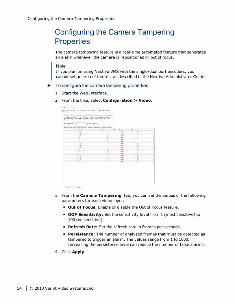
Configuring the Camera TamperingPropertiesThe camera tampering feature is a real-time automated feature that generatesan alarm whenever the camera is repositioned or out of focus.
NoteIf you plan on using Nextiva VMS with the single/dual port encoders, youcannot set an area of interest as described in the Nextiva Administrator Guide.
► To configure the camera tampering properties1. Start the Web Interface.
2. From the tree, select Configuration > Video.
3. From the Camera Tampering tab, you can set the values of the followingparameters for each video input:
Out of Focus: Enable or disable the Out of Focus feature.
OOF Sensitivity: Set the sensitivity level from 1 (most sensitive) to100 (no sensitive).
Refresh Rate: Set the refresh rate in frames per seconds.
Persistence: The number of analyzed frames that must be detected astampered to trigger an alarm. The values range from 1 to 1000.Increasing the persistence level can reduce the number of false alarms.
4. Click Apply.
Configuring the Camera Tampering Properties
54 © 2013 Verint Video Systems Inc.
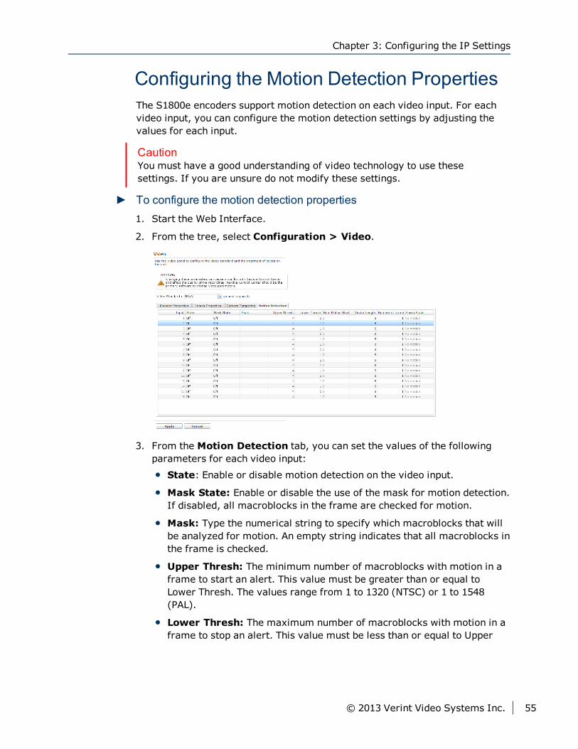
Configuring the Motion Detection PropertiesThe S1800e encoders support motion detection on each video input. For eachvideo input, you can configure the motion detection settings by adjusting thevalues for each input.
CautionYou must have a good understanding of video technology to use thesesettings. If you are unsure do not modify these settings.
► To configure the motion detection properties1. Start the Web Interface.
2. From the tree, select Configuration > Video.
3. From the Motion Detection tab, you can set the values of the followingparameters for each video input:
State: Enable or disable motion detection on the video input.
Mask State: Enable or disable the use of the mask for motion detection.If disabled, all macroblocks in the frame are checked for motion.
Mask: Type the numerical string to specify which macroblocks that willbe analyzed for motion. An empty string indicates that all macroblocks inthe frame is checked.
Upper Thresh: The minimum number of macroblocks with motion in aframe to start an alert. This value must be greater than or equal toLower Thresh. The values range from 1 to 1320 (NTSC) or 1 to 1548(PAL).
Lower Thresh: The maximum number of macroblocks with motion in aframe to stop an alert. This value must be less than or equal to Upper
Chapter 3: Configuring the IP Settings
© 2013 Verint Video Systems Inc. 55
Thresh. The values range from 1 to 1320 (NTSC) or 1 to 1548 (PAL).
Vector Length: The amount of motion in a given macroblocks that mustbe present to tag this as in motion. The values range from 0 to 255.
Number of Frames: The number of consecutive frames that must bedetected as a new motion. The values range from 1 to 1000.
4. Click Apply.
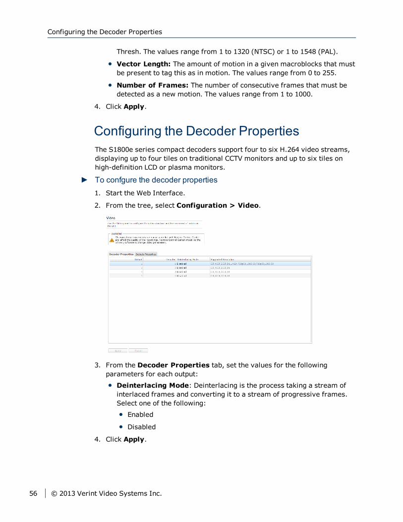
Configuring the Decoder PropertiesThe S1800e series compact decoders support four to six H.264 video streams,displaying up to four tiles on traditional CCTV monitors and up to six tiles onhigh-definition LCD or plasma monitors.
► To confgure the decoder properties1. Start the Web Interface.
2. From the tree, select Configuration > Video.
3. From the Decoder Properties tab, set the values for the followingparameters for each output:
Deinterlacing Mode: Deinterlacing is the process taking a stream ofinterlaced frames and converting it to a stream of progressive frames.Select one of the following:
Enabled
Disabled
4. Click Apply.
Configuring the Decoder Properties
56 © 2013 Verint Video Systems Inc.
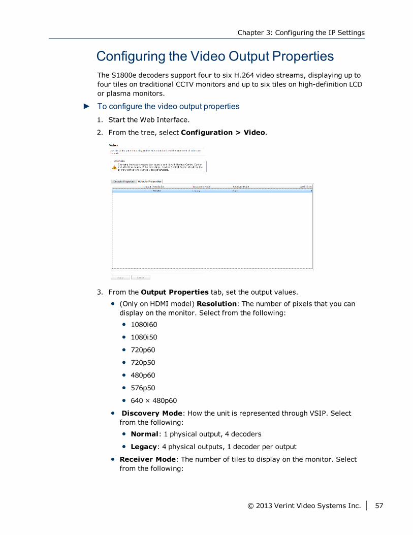
Configuring the Video Output PropertiesThe S1800e decoders support four to six H.264 video streams, displaying up tofour tiles on traditional CCTV monitors and up to six tiles on high-definition LCDor plasma monitors.
► To configure the video output properties1. Start the Web Interface.
2. From the tree, select Configuration > Video.
3. From the Output Properties tab, set the output values.
(Only on HDMI model) Resolution: The number of pixels that you candisplay on the monitor. Select from the following:
1080i60
1080i50
720p60
720p50
480p60
576p50
640 × 480p60
Discovery Mode: How the unit is represented through VSIP. Selectfrom the following:
Normal: 1 physical output, 4 decoders
Legacy: 4 physical outputs, 1 decoder per output
Receiver Mode: The number of tiles to display on the monitor. Selectfrom the following:
Chapter 3: Configuring the IP Settings
© 2013 Verint Video Systems Inc. 57
Single: Video from one stream is displayed on the monitor.
Quad: The monitor is divided into four quadrants and each displayingvideo from four different streams.
3 × 2: (Only on HDMI model) The monitor displays video from sixdifferent streams.
Guard Tour: Video from each stream is displayed on the monitor oneafter another.
Dwell Time: The number of seconds to display video from a selectedcamera before switching to the next camera in the tour.
4. Click Apply.
Setting the SNMP PropertiesSimple Network Management Protocol (SNMP) is a protocol used by networkmanagement systems to manage network equipments from a central location.The S1800e devices are SNMP-compliant and store data about themselves inManagement Information Bases (MIBs) and return this data (SNMP Traps) tothe SNMP requesters.
Setting the SNMP Properties
58 © 2013 Verint Video Systems Inc.
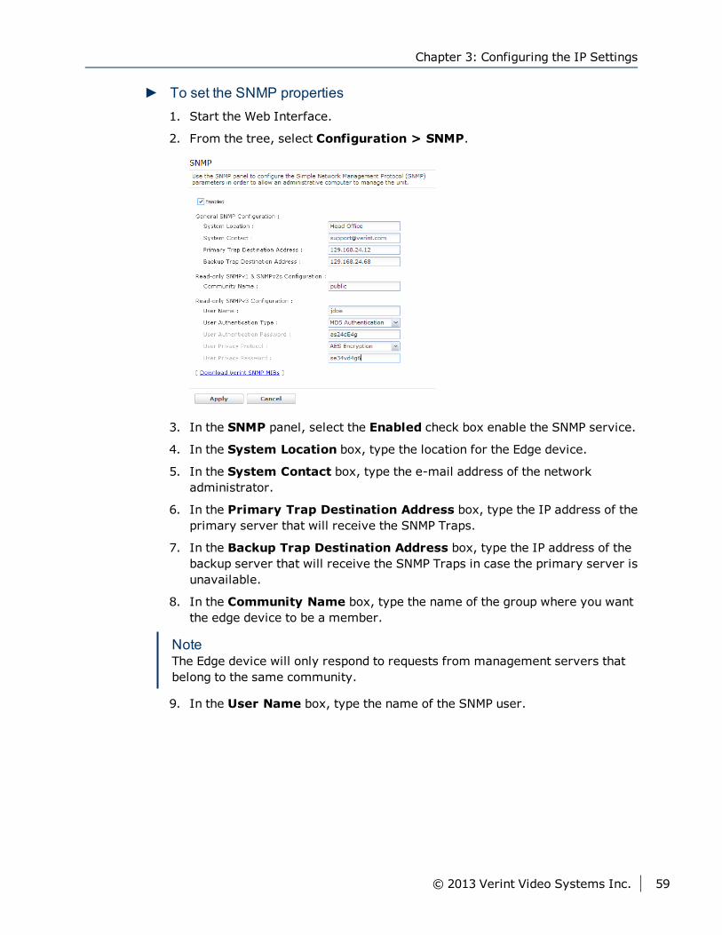
► To set the SNMP properties1. Start the Web Interface.
2. From the tree, select Configuration > SNMP.
3. In the SNMP panel, select the Enabled check box enable the SNMP service.
4. In the System Location box, type the location for the Edge device.
5. In the System Contact box, type the e-mail address of the networkadministrator.
6. In the Primary Trap Destination Address box, type the IP address of theprimary server that will receive the SNMP Traps.
7. In the Backup Trap Destination Address box, type the IP address of thebackup server that will receive the SNMP Traps in case the primary server isunavailable.
8. In the Community Name box, type the name of the group where you wantthe edge device to be a member.
NoteThe Edge device will only respond to requests from management servers thatbelong to the same community.
9. In the User Name box, type the name of the SNMP user.
Chapter 3: Configuring the IP Settings
© 2013 Verint Video Systems Inc. 59
10. In the User Authentication Type list, select the authentication algorithmfor SNMP requests. You can select from the following:
No Authentication: No authentication is used.
MD5 Authentication: The Message Digest Version 5 (MD5) hashfunction is used to determine that the message is from a valid source.
SHA Authentication: The Secure Hash Algorithm (SHA) has function isused to determine that the message is from a valid source.
11. In the User Authentication Password box, type a password for the user.
12. In the User Privacy Protocol list, select the privacy protocol to encryptthe contents of the data. You can select from the following:
No Encryption: No encryption is used.
DES Encryption: The Data Encryption Standard (DES) algorithm is usedto encrypt the data.
AES Encryption: The Advanced Encryption Standard (AES) algorithm isused to encrypt the data.
13. In the User Privacy Password box, type a password for the privacyprotocol.
14. Click Apply.
Viewing MIB InformationYou can download the device Management Information Base (MIB) and use aSNMP application to view the information. The MIB is a collection ofmanageable entities of the device network element.
The S1800e series device sends a coldStart trap when it is initialized and sendsthe following Verint-Specific SNMP traps:
Video Signal Loss edVinMediaStateAnalogNotif trap. This trap is generated ifan analog video input of an S1800e series device is disconnected orreconnected with the following information:
Input number (1 to 16 for S1816e and S1816e-SP, 1 to 8 for S1808e)
New state (0: not connected, 1: connected)
Dry Input State Change edDigitalinPinStateNotif trap. This trap is generatedif the status of a digital alarm dry contact input of the S1800e device haschanged with the following information:
Input number (1 to 16 for S1816e and S1816e-SP, 1 to 8 for S1808e)
New state (0: not connected, 1: connected)
Viewing MIB Information
60 © 2013 Verint Video Systems Inc.
edVinCamtampOofAlarmStateNotif trap. This trap is generated if the Out OfFocus status of an input has changed with the following information:
[0x00]= Not Out Of Focus
[0x01]= Out Of Focus
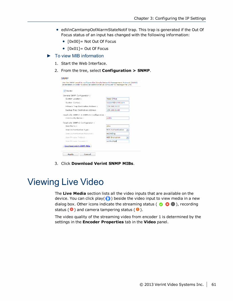
► To view MIB information1. Start the Web Interface.
2. From the tree, select Configuration > SNMP.
3. Click Download Verint SNMP MIBs.
Viewing Live VideoThe Live Media section lists all the video inputs that are available on thedevice. You can click play( ) beside the video input to view media in a newdialog box. Other icons indicate the streaming status ( ), recordingstatus ( ) and camera tampering status ( ).
The video quality of the streaming video from encoder 1 is determined by thesettings in the Encoder Properties tab in the Video panel.
Chapter 3: Configuring the IP Settings
© 2013 Verint Video Systems Inc. 61
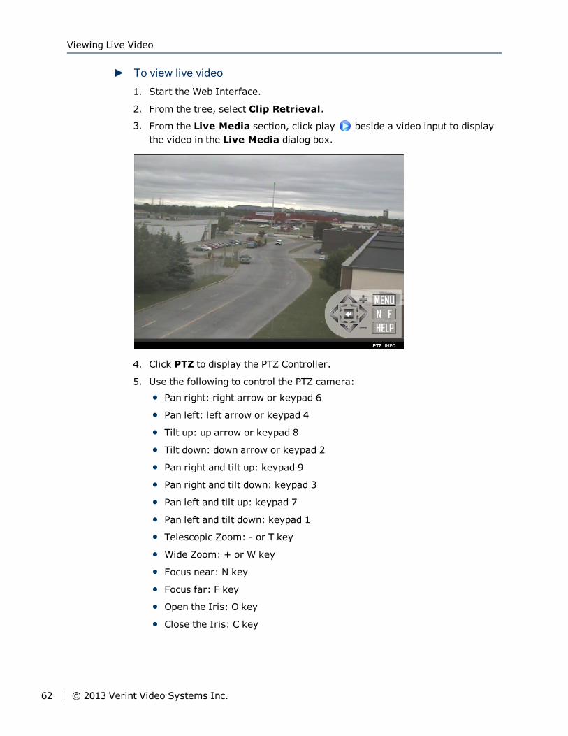
► To view live video1. Start the Web Interface.
2. From the tree, select Clip Retrieval.
3. From the Live Media section, click play beside a video input to displaythe video in the Live Media dialog box.
4. Click PTZ to display the PTZ Controller.
5. Use the following to control the PTZ camera:
Pan right: right arrow or keypad 6
Pan left: left arrow or keypad 4
Tilt up: up arrow or keypad 8
Tilt down: down arrow or keypad 2
Pan right and tilt up: keypad 9
Pan right and tilt down: keypad 3
Pan left and tilt up: keypad 7
Pan left and tilt down: keypad 1
Telescopic Zoom: - or T key
Wide Zoom: + or W key
Focus near: N key
Focus far: F key
Open the Iris: O key
Close the Iris: C key
Viewing Live Video
62 © 2013 Verint Video Systems Inc.
The PTZ menu allows you to perform the following:
Menu: Displays the on-screen menu. For more information on the PTZ on-screen menu.
Help: Displays the PTZ Control Usage.
Use the following to control the PTZ camera:
Pan right: right arrow or keypad 6
Pan left: left arrow or keypad 4
Tilt up: up arrow or keypad 8
Tilt down: down arrow or keypad 2
Pan right and tilt up: keypad 9
Pan right and tilt down: keypad 3
Pan left and tilt up: keypad 7
Pan left and tilt down: keypad 1
Telescopic Zoom: - or T key
Wide Zoom: + or W key
Focus near: N key
Focus far: F key
Open the Iris: O key
Close the Iris: C key
NoteIn the Live Media dialog box, click INFO to display Frame Rate andresolution information in the top right corner.
Chapter 3: Configuring the IP Settings
© 2013 Verint Video Systems Inc. 63
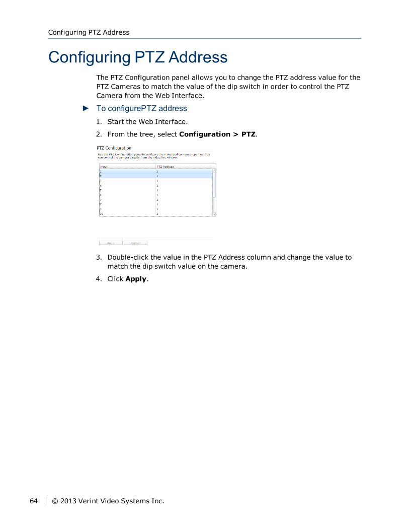
Configuring PTZ AddressThe PTZ Configuration panel allows you to change the PTZ address value for thePTZ Cameras to match the value of the dip switch in order to control the PTZCamera from the Web Interface.
► To configurePTZ address1. Start the Web Interface.
2. From the tree, select Configuration > PTZ.
3. Double-click the value in the PTZ Address column and change the value tomatch the dip switch value on the camera.
4. Click Apply.
Configuring PTZ Address
64 © 2013 Verint Video Systems Inc.
Once the camera is installed and the network settings configured, you need toconfigure the camera properties using the On-screen Display (OSD) menu.
The following topics are discussed:
Configuring the Nextiva S5500 PTZ Series 66
Using the Nextiva S5500 PTZ Series Menu Options 69
Setting Up the Camera 76
Setting Up Horizontal Pan and Vertical Tilt 83
Setting the Camera Title 87
Setting Up the Presets 88
Auto Patrol 88
Setting up the Additional Functions 91
Freeze Activity 91
Setting up the System 93
Setting the Week 93
Using the Nextiva S5500 IP PTZ Preset Commands 98
Chapter 4Chapter 4: Configuring the Nextiva S5500
PTZ Series Properties
Configuring the Nextiva S5500 PTZ SeriesOnce the camera is installed, you need to configure the camera propertiesusing the On-screen Display (OSD) menu.
Activating the OSDMenuThere are multiple ways to access the OSD menu:
1. Nextiva Virtual Matrix: In this setup, external components such asanalog or digital monitors and CCTV keyboards are connected to Nextiva viaan edge device. Using Nextiva Control Center, you can configure externalCCTV or HD monitors and CCTV keyboards to control and display views fromPTZ cameras as needed. Either Nextiva Review or the CCTV keyboard cancontrol the PTZ cameras independently.
2. Analog Matrix Device: In this setup, the CCTV keyboard is connecteddirectly to a rack-mounted matrix device (hardwired). You can use theexternal keyboard to control PTZ cameras and display the video on analogmonitors, but the external keyboards and analog monitors are notintegrated with the Nextiva system. Therefore, camera tours, salvos, andother PTZ camera operation features that must be set up through NextivaControl Center are not available.
3. Nextiva Review: control PTZ cameras through the Nextiva Reviewapplication.
► To display the OSD menu from Nextiva Review:
1. In the application tabs, click Live .
2. In the left pane, click Pan/tilt/zoom (PTZ) camera
3. From the PTZ toolbar, click the camera menu .
► To activate the OSD menu using a keypad:1. For keypad controllers that are compatible with Pelco D, press the number
keys “95” and then press and hold the “PRESET” key for two seconds toactivate the OSD menu.
NoteDifferent keypad controller may use different commands to activate the OSDmenu may differ with the connected keypad controller.
Configuring the Nextiva S5500 PTZ Series
66 © 2013 Verint Video Systems Inc.
Using Nextiva Review to Configure theNextiva S5500 PTZ SeriesNextiva Review supports pan/tilt/zoom (PTZ) functionality for live video when aPTZ camera is selected in Live mode. You can control PTZ cameras throughReview by using the Heads Up Display (HUD) control panel and the PTZ toolbar.The PTZ toolbar contains the buttons used to control a PTZ camera in theReview workspace.
NoteIf external CCTV keyboards are installed, they can also be used to control PTZcameras. In this case, you might see the camera move around in Reviewwithout providing any input through the Review interface.
► To display the PTZ toolbar1. In the application tabs, click Live .
2. In the left pane, navigate to the PTZ camera you want to access.Pan/tilt/zoom (PTZ) camera
PTZ camera with audio
3. Display live video from the camera using one of these methods:
Drag the required camera from the camera tree into a tile in theworkspace. The video opens in the selected tile and starts playing livevideo images.
Double-click the camera name in the camera tree. The video opens andstarts playing in the next available tile. If all video tiles are full, thenewly selected camera replaces the item in the currently active tile.
4. Click the video tile for the PTZ camera to display the PTZ toolbar.
NoteIf your user account does not have privileges to control PTZ cameras, thePTZ toolbar does not appear. You can use the controls on the regular videotile toolbar as if the camera was a fixed (non-PTZ) camera.
Chapter 4: Configuring the Nextiva S5500 PTZ Series Properties
© 2013 Verint Video Systems Inc. 67
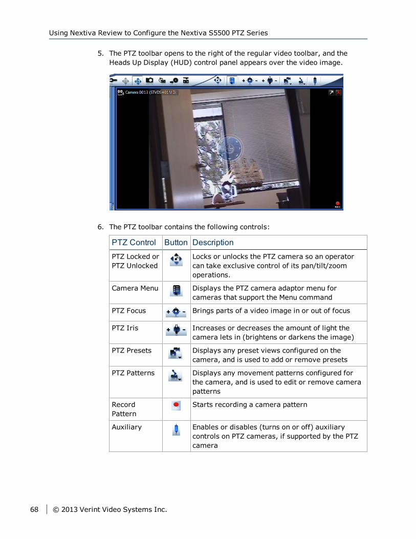
5. The PTZ toolbar opens to the right of the regular video toolbar, and theHeads Up Display (HUD) control panel appears over the video image.
6. The PTZ toolbar contains the following controls:
PTZ Control Button Description
PTZ Locked orPTZ Unlocked
Locks or unlocks the PTZ camera so an operatorcan take exclusive control of its pan/tilt/zoomoperations.
Camera Menu Displays the PTZ camera adaptor menu forcameras that support the Menu command
PTZ Focus Brings parts of a video image in or out of focus
PTZ Iris Increases or decreases the amount of light thecamera lets in (brightens or darkens the image)
PTZ Presets Displays any preset views configured on thecamera, and is used to add or remove presets
PTZ Patterns Displays any movement patterns configured forthe camera, and is used to edit or remove camerapatterns
RecordPattern
Starts recording a camera pattern
Auxiliary Enables or disables (turns on or off) auxiliarycontrols on PTZ cameras, if supported by the PTZcamera
Using Nextiva Review to Configure the Nextiva S5500 PTZ Series
68 © 2013 Verint Video Systems Inc.
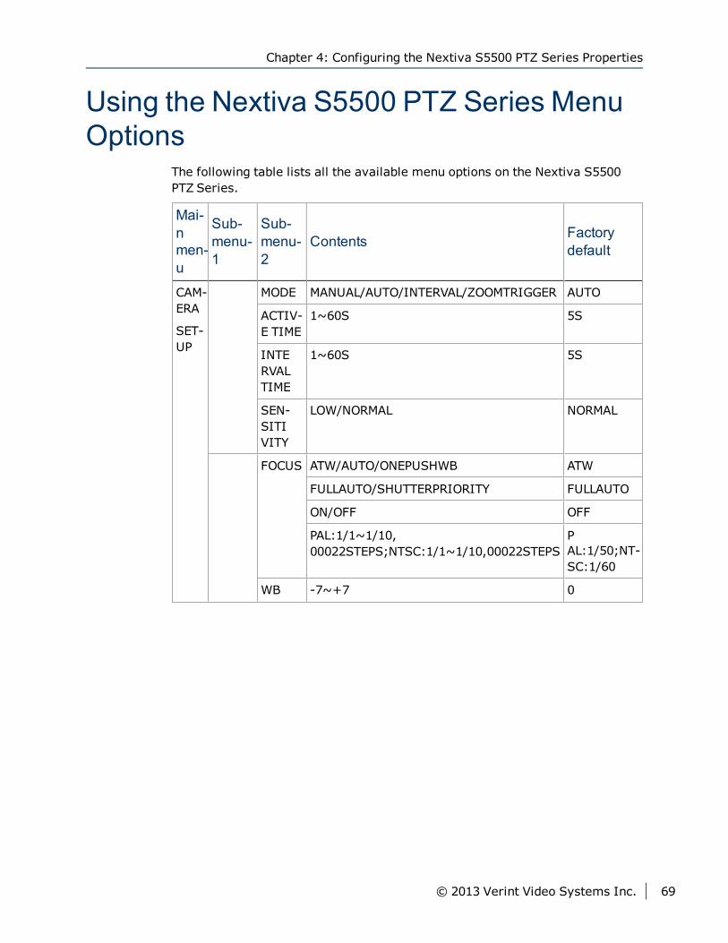
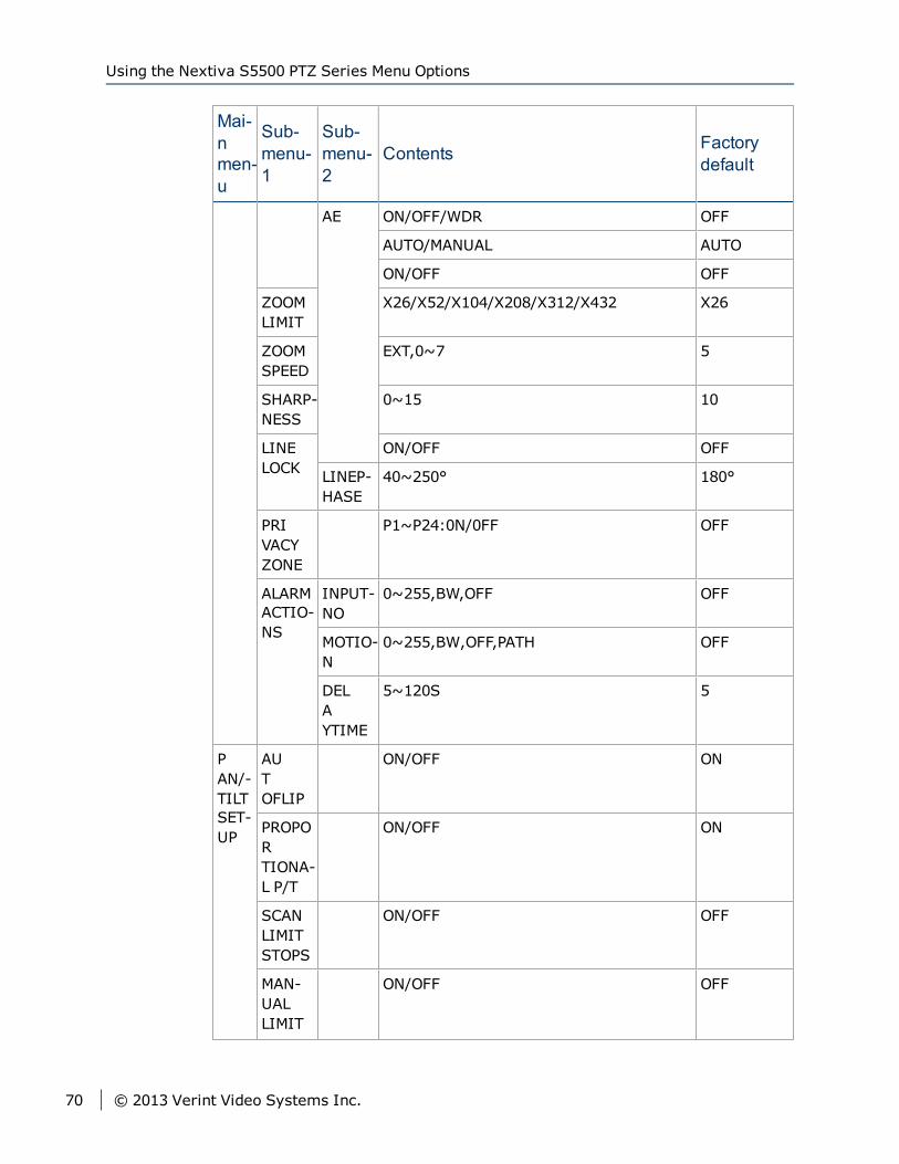
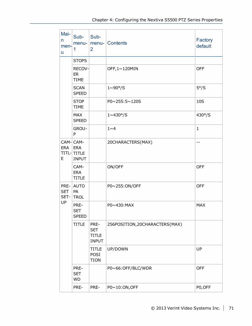
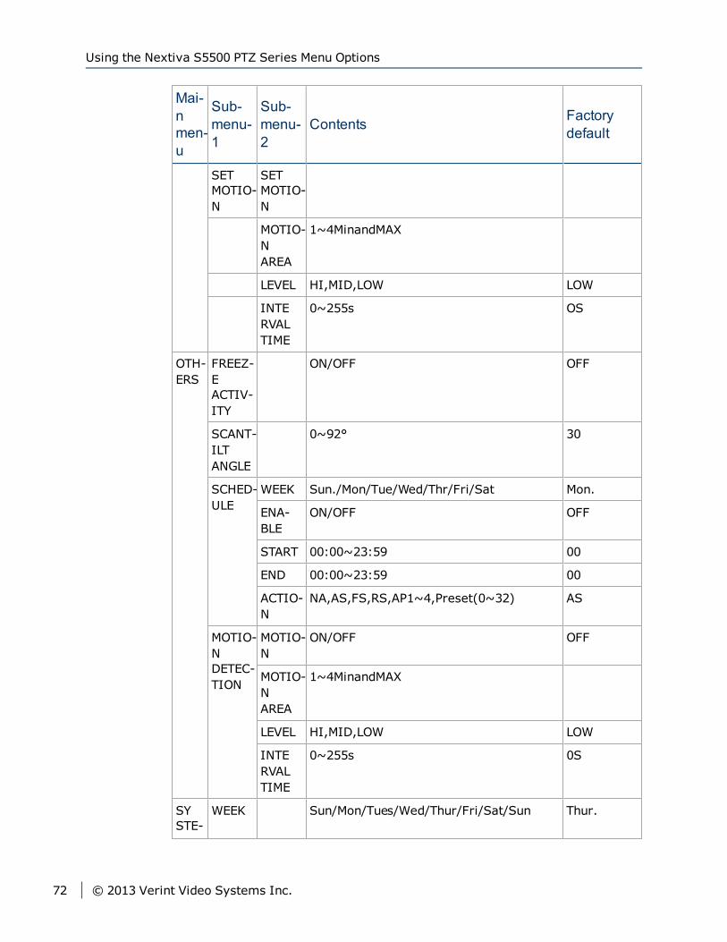
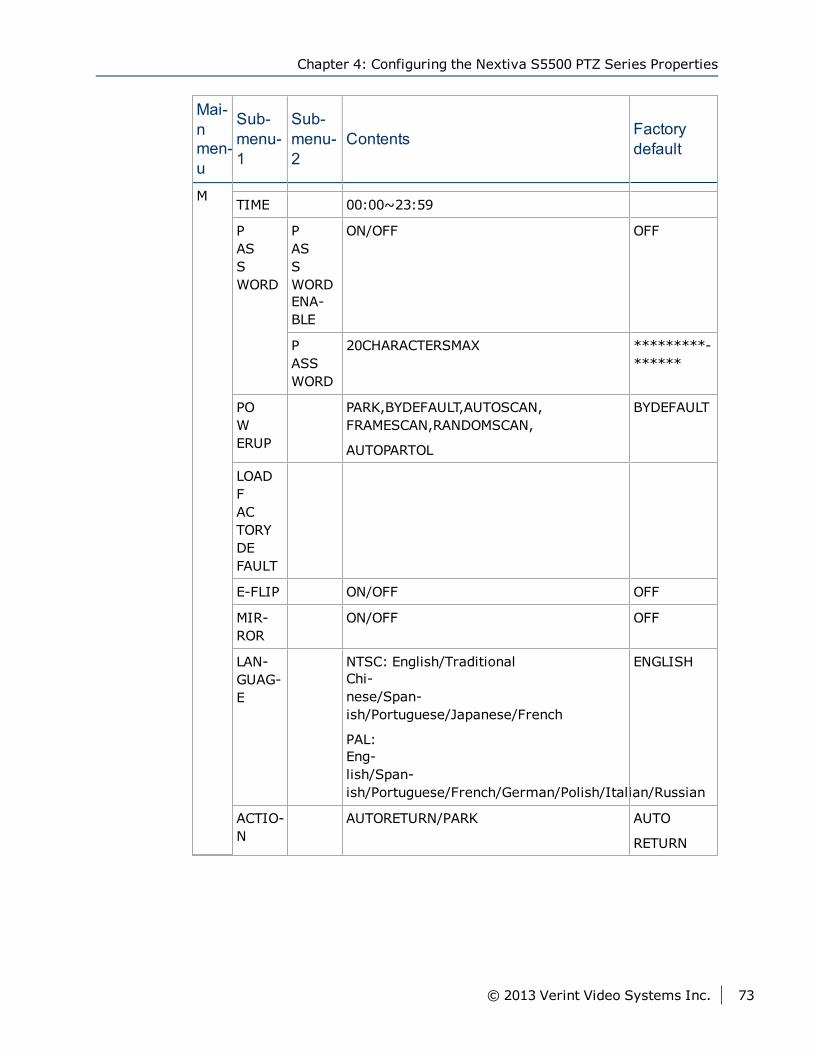
Using the Nextiva S5500 PTZ Series MenuOptions
The following table lists all the available menu options on the Nextiva S5500PTZ Series.
Mai-nmen-u
Sub-menu-1
Sub-menu-2
Contents Factorydefault
CAM-ERA
SET-UP
MODE MANUAL/AUTO/INTERVAL/ZOOMTRIGGER AUTO
ACTIV-E TIME
1~60S 5S
INTERVALTIME
1~60S 5S
SEN-SITIVITY
LOW/NORMAL NORMAL
FOCUS ATW/AUTO/ONEPUSHWB ATW
FULLAUTO/SHUTTERPRIORITY FULLAUTO
ON/OFF OFF
PAL:1/1~1/10,00022STEPS;NTSC:1/1~1/10,00022STEPS
PAL:1/50;NT-SC:1/60
WB -7~+7 0
Chapter 4: Configuring the Nextiva S5500 PTZ Series Properties
© 2013 Verint Video Systems Inc. 69
Mai-nmen-u
Sub-menu-1
Sub-menu-2
Contents Factorydefault
AE ON/OFF/WDR OFF
AUTO/MANUAL AUTO
ON/OFF OFF
ZOOMLIMIT
X26/X52/X104/X208/X312/X432 X26
ZOOMSPEED
EXT,0~7 5
SHARP-NESS
0~15 10
LINELOCK
ON/OFF OFF
LINEP-HASE
40~250° 180°
PRIVACYZONE
P1~P24:0N/0FF OFF
ALARMACTIO-NS
INPUT-NO
0~255,BW,OFF OFF
MOTIO-N
0~255,BW,OFF,PATH OFF
DELAYTIME
5~120S 5
PAN/-TILTSET-UP
AUTOFLIP
ON/OFF ON
PROPORTIONA-L P/T
ON/OFF ON
SCANLIMITSTOPS
ON/OFF OFF
MAN-UALLIMIT
ON/OFF OFF
Using the Nextiva S5500 PTZ Series Menu Options
70 © 2013 Verint Video Systems Inc.
Mai-nmen-u
Sub-menu-1
Sub-menu-2
Contents Factorydefault
STOPS
RECOV-ERTIME
OFF,1~120MIN OFF
SCANSPEED
1~90°/S 5°/S
STOPTIME
P0~255:5~120S 10S
MAXSPEED
1~430°/S 430°/S
GROU-P
1~4 1
CAM-ERATITL-E
CAM-ERATITLEINPUT
20CHARACTERS(MAX) --
CAM-ERATITLE
ON/OFF OFF
PRE-SETSET-UP
AUTOPATROL
P0~255:ON/OFF OFF
PRE-SETSPEED
P0~430:MAX MAX
TITLE PRE-SETTITLEINPUT
256POSITION,20CHARACTERS(MAX)
TITLEPOSITION
UP/DOWN UP
PRE-SETWD
P0~66:OFF/BLC/WDR OFF
PRE- PRE- P0~10:ON,OFF P0,OFF
Chapter 4: Configuring the Nextiva S5500 PTZ Series Properties
© 2013 Verint Video Systems Inc. 71
Mai-nmen-u
Sub-menu-1
Sub-menu-2
Contents Factorydefault
SETMOTIO-N
SETMOTIO-N
MOTIO-NAREA
1~4MinandMAX
LEVEL HI,MID,LOW LOW
INTERVALTIME
0~255s OS
OTH-ERS
FREEZ-EACTIV-ITY
ON/OFF OFF
SCANT-ILTANGLE
0~92° 30
SCHED-ULE
WEEK Sun./Mon/Tue/Wed/Thr/Fri/Sat Mon.
ENA-BLE
ON/OFF OFF
START 00:00~23:59 00
END 00:00~23:59 00
ACTIO-N
NA,AS,FS,RS,AP1~4,Preset(0~32) AS
MOTIO-NDETEC-TION
MOTIO-N
ON/OFF OFF
MOTIO-NAREA
1~4MinandMAX
LEVEL HI,MID,LOW LOW
INTERVALTIME
0~255s 0S
SYSTE-
WEEK Sun/Mon/Tues/Wed/Thur/Fri/Sat/Sun Thur.
Using the Nextiva S5500 PTZ Series Menu Options
72 © 2013 Verint Video Systems Inc.
Mai-nmen-u
Sub-menu-1
Sub-menu-2
Contents Factorydefault
M TIME 00:00~23:59
PASSWORD
PASSWORDENA-BLE
ON/OFF OFF
PASSWORD
20CHARACTERSMAX *********-******
POWERUP
PARK,BYDEFAULT,AUTOSCAN,FRAMESCAN,RANDOMSCAN,
AUTOPARTOL
BYDEFAULT
LOADFACTORYDEFAULT
E-FLIP ON/OFF OFF
MIR-ROR
ON/OFF OFF
LAN-GUAG-E
NTSC: English/TraditionalChi-nese/Span-ish/Portuguese/Japanese/French
PAL:Eng-lish/Span-ish/Portuguese/French/German/Polish/Italian/Russian
ENGLISH
ACTIO-N
AUTORETURN/PARK AUTO
RETURN
Chapter 4: Configuring the Nextiva S5500 PTZ Series Properties
© 2013 Verint Video Systems Inc. 73
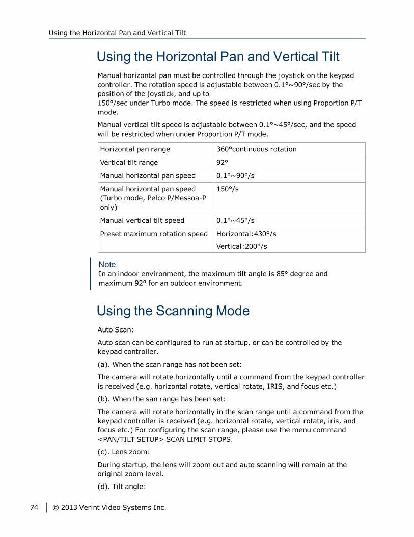
Using the Horizontal Pan and Vertical TiltManual horizontal pan must be controlled through the joystick on the keypadcontroller. The rotation speed is adjustable between 0.1°~90°/sec by theposition of the joystick, and up to150°/sec under Turbo mode. The speed is restricted when using Proportion P/Tmode.
Manual vertical tilt speed is adjustable between 0.1°~45°/sec, and the speedwill be restricted when under Proportion P/T mode.
Horizontal pan range 360°continuous rotation
Vertical tilt range 92°
Manual horizontal pan speed 0.1°~90°/s
Manual horizontal pan speed(Turbo mode, Pelco P/Messoa-Ponly)
150°/s
Manual vertical tilt speed 0.1°~45°/s
Preset maximum rotation speed Horizontal:430°/s
Vertical:200°/s
NoteIn an indoor environment, the maximum tilt angle is 85° degree andmaximum 92° for an outdoor environment.
Using the Scanning ModeAuto Scan:
Auto scan can be configured to run at startup, or can be controlled by thekeypad controller.
(a). When the scan range has not been set:
The camera will rotate horizontally until a command from the keypad controlleris received (e.g. horizontal rotate, vertical rotate, IRIS, and focus etc.)
(b). When the san range has been set:
The camera will rotate horizontally in the scan range until a command from thekeypad controller is received (e.g. horizontal rotate, vertical rotate, iris, andfocus etc.) For configuring the scan range, please use the menu command<PAN/TILT SETUP> SCAN LIMIT STOPS.
(c). Lens zoom:
During startup, the lens will zoom out and auto scanning will remain at theoriginal zoom level.
(d). Tilt angle:
Using the Horizontal Pan and Vertical Tilt
74 © 2013 Verint Video Systems Inc.
During startup, the camera will perform vertical scanning from the tilt anglesetting. For configuring the tilt angle, please use the menu command<OTHERS> SCAN TILT ANGLE. When the keypad controller issues auto-scanning command, the tilt angle will remain at the original setting.
Frame Scanning:
Frame scanning can be configured to run at startup, or can be controlled by thekeypad controller (refer to the table in Chapter 8). Configuring the zoom leveland tilt angle is the same as in auto scanning.
(a). When the scan range has not been set:
The camera will scan at 45° increments until a command from the keypadcontroller is received (e.g. horizontal rotate, vertical rotate, iris, and focusetc.) Please refer to the diagram below.
Random Scanning:
Random scanning can be configure to run at startup, or can be controlled by thekeypad controller. Configuring the zoom level and tilt angle is same as in autoscanning.
(a). When the scan range has been set: (figure.1)
The camera will randomly pick a stop point and perform scanning until acommand from the keypad controller is received (e.g. horizontal rotate,vertical rotate, iris, and focus etc.) Please refer to the diagram below.
(b). When the scan range has been set: (figure.2)
The camera will randomly pick a stop point and perform scanning in the scanrange until a command from the keypad controller is received (e.g. horizontalrotate, vertical rotate, iris, and focus etc.)
NoteUse the menu command <PAN/TILT SETUP> STOP TIME (P0) to configure thestop time, range from 5 sec to 120 sec.
Chapter 4: Configuring the Nextiva S5500 PTZ Series Properties
© 2013 Verint Video Systems Inc. 75
Setting Up the CameraThe following section provides information on setting up the camera.
Setting the Focus<CAMERA SETUP> → <FOCUS> → Mode
Use the [NEAR] or [FAR] keys to control the Focus.
One push auto focus feature.
Four focus modes to choose from: Manual, Auto, Interval, and Zoom.
Under manual focus, use the [NEAR] and [FAR] keys to control the Focus.
Under auto focus mode, press the [NEAR] or [FAR] keys to switch to manualfocus mode until the commands for lens zoom, horizontal, and verticalrotate button control signals are received.
Under interval mode, the camera will switch between auto focus and manualfocus modes according to the Active time and Interval time settings: ActiveTime (auto)→ Interval Time (manual)→Active Time (auto)→ IntervalTime (manual). 5
Interval and Active time settings range between 0 and 255 seconds.
Under Zoom trigger mode, the camera will remain under manual focusmode until the control signals for [ZOOM IN] or [ZOOM OUT] are receivedfrom the keypad. After the action is carried out, the camera will return tomanual focus mode.
Auto focus sensitivity can be set to Normal or Low.
► To set the focus setting:1. Press “95” + hold the [PRESET] key for 2 seconds to enter the mainmenu
screen.
2. Move the cursor to <CAMERA SETUP>, and then press the [OPEN] key toenter <CAMERA SETUP> menu.
3. Move the cursor to <FOCUS>, and then press the [OPEN] key to enter<FOCUS> menu.
4. Move the cursor to <MODE>, and then press the [OPEN] key to enter modeselection menu.
5. Move the joystick up and down to choose the function to use.
6. Press the [OPEN] key to confirm, or press [CLOSE] to cancel selection andexit from the menu screen.
Setting Up the Camera
76 © 2013 Verint Video Systems Inc.
Setting the White Balance<CAMERA SETUP> → WB
Provides three modes of white balance:
ATW: White balance range from 2000°K to 10000°K.
AUTO: White balance range from 3000°K to 7500°K.
ONE PUSH WB: Use the hotkey combination (number “73”+ [PRESET] key)to activate ONE PUSH white balance (ONE PUSH WB mode has to beenabled).
► To set the white balance:1. Press “95” + hold the [PRESET] key for 2 seconds to enter the mainmenu
screen.
2. Move the cursor to <CAMERA SETUP>, and then press the [OPEN] key toenter <CAMERA SETUP> menu.
3. Move the cursor to WB, and then press the [OPEN] key to enter WBmodeselection.
4. Move the joystick up/down to make the selection.
5. Press the [OPEN] key to confirm the selection or press the [CLOSE] key tocancel selection and exit from the menu screen.
Setting the Auto Exposure (AE)<CAMERA SETUP> → <AE>
The aperture can be directly controlled by the [OPEN] or [CLOSE] keys.
AE mode: FULL AUTO / SHUTTER PRIORITY.
Under FULL AUTO mode, the shutter speed is set at 1/60 sec (NTSC) or1/50 sec (PAL) and the camera will automatically adjust the apertureaccording to the amount of outside light.
Under FULL AUTO mode, the aperture can be manually controlled; butonce the zoom or horizontal pan/vertical tilt command is received, thecamera will return to FULL AUTO mode.
Under SHUTTER PRIORITY mode, the shutter speed ranges between 1/1~1/10,000 seconds, with 22 steps.
AUTO SLOW SHUTTER can be either ON or OFF.
AE COMPENSATION can range between -7 to +7.
BACK LIGHT COMP can be either ON or OFF, or directly controlled by thekeypad (number “71”+ [PRESET] key = ON; number “72”+ [PRESET] key =OFF)
Chapter 4: Configuring the Nextiva S5500 PTZ Series Properties
© 2013 Verint Video Systems Inc. 77
DAY/NIGHTmode can be either automatic or manual. To improve nighttimesensitivity, the infrared filter in the camera lens can be removed. When set toauto mode, the camera will automatically adjust according to theenvironment brightness; under manual mode, directly press the keys number“88”+ [PRESET] key = Daytime color mode; number “89”+ [PRESET] key =Nighttimemonochrome mode.
FLICKERLESS: ON or OFF.
NoteBLC function is selectable: ON/OFF, or refer to hotkey operation. For domewith WDR, the selection for BLC function would be: ON/OFF/WDR (For WDRmodel only).
► To set the auto exposure:1. Press “95” + hold the [PRESET] key for 2 seconds to enter the main menu
screen.
2. Move the cursor to <CAMERA SETUP>, and then press the [OPEN] key<CAMERA SETUP> menu.
3. Move the cursor to AE, and then press the [OPEN] key to enter AE modeselection.
4. Move the cursor to the selection and then press the [OPEN] key.
5. Move the joystick up/down to choose the selection.
6. Press the [OPEN] key to confirm the selection or press the [CLOSE] key tocancel selection and exit from the menu screen.
Setting the Zoom Limit<CAMERA SETUP> → ZOOM LIMIT
Directly set as wide or tele mode.
Zoom levels: up to X36.
Max optical zoom level is X36, digital zoom level starts from X72 to X432.
NoteThe actually zoom level depends on different model.
► To adjust the Zoom Limit:1. Press “95” + hold the [PRESET] key for 2 seconds to enter the mainmenu
screen.
2. Move the cursor to <CAMERA SETUP>, and then press the [OPEN] key<CAMERA SETUP> menu.
3. Move the cursor to ZOOM LIMIT, and then press the [OPEN] key zoom levelselection.
Setting the Zoom Limit
78 © 2013 Verint Video Systems Inc.
4. Move the joystick up/down to choose the zoom level selection.
5. Press the [OPEN] key to confirm the selection or press the [CLOSE] key tocancel selection and exit from the menu screen.
Setting the Zoom SpeedThere are nine steps of zoom speed for the lens 0 ~ 7 that can be selected fromthe menu. When set to EXT mode, the command has to be issued through theRS485 interface.
► To adjust the zoom Speed:1. Press “95” + hold the [PRESET] key for 2 seconds to enter the mainmenu
screen.
2. Move the cursor to <CAMERA SETUP>, and then press the [OPEN] key<CAMERA SETUP> menu.
3. Move the cursor to ZOOM SPEED, and then press the [OPEN] key zoomspeed selection.
4. Move the joystick up/down to choose the zoom speed selection.
5. Press the [OPEN] key to confirm the selection or press the [CLOSE] key tocancel selection and exit from the menu screen.
Setting the Sharpness<CAMERA SETUP> → SHARPNESS
Sharpness control ranges from 0 to 15 (15 is the sharpest).
► To set the sharpness:1. Press “95” + hold the [PRESET] key for 2 seconds to enter the mainmenu
screen.
2. Move the cursor to <CAMERA SETUP>, and then press the [OPEN] key<CAMERA SETUP> menu.
3. Move the cursor to SHARPNESS, and then press the [OPEN] key sharpnessselection.
4. Move the joystick up/down to choose the appropriate sharpness selection.
5. Press the [OPEN] key to confirm the selection or press the [CLOSE] key tocancel selection and exit from the menu screen.
Setting the Line Lock<CAMERA SETUP> → LINE LOCK
Chapter 4: Configuring the Nextiva S5500 PTZ Series Properties
© 2013 Verint Video Systems Inc. 79
The camera can use the power line frequency as the sync signal source.
Line Lock can be set to ON or OFF
Line Phase range between 40° ~ 250°
► To set the line lock:1. Press “95” + hold the [PRESET] key for 2 seconds to enter the mainmenu
screen.
2. Move the cursor to <CAMERA SETUP>, and then press the [OPEN] key<CAMERA SETUP> menu.
3. Move the cursor to <LINE LOCK>, and then press the [OPEN] key <LINELOCK> mode selection.
4. Move the cursor to the selection and then press the [OPEN] key.
5. Move the joystick up/down to choose the selection.
6. Press the [OPEN] key to confirm the selection or press the [CLOSE] key tocancel selection and exit from the menu screen.
Setting Privacy Zones<CAMERA SETUP> → PRIVACY ZONES
This feature can enable the user to black out (or white out) a specific portion ofthe screen to protect the necessary privacy. The size and position of theseframe areas can be adjusted according to the horizontal pan, vertical tilt, andlens zoom of the camera. Up to 24 frame zones can be configured.
► To set a privacy zone:1. Press “95” + hold the [PRESET] key for 2 seconds to enter the mainmenu
screen.
2. Move the cursor to <CAMERA SETUP>, and then press the [OPEN] key<CAMERA SETUP> menu.
3. Move the cursor to PRIVACY ZONE, and then press the [OPEN] key theselection.
4. Move the joystick up/down to set the P1~P24 ON/OFF selection.
5. Press the [OPEN] key to confirm the selection or press the [CLOSE] key tocancel selection and exit from the menu screen.
Setting Privacy Zones
80 © 2013 Verint Video Systems Inc.
► To Set Privacy Zone Size and Position using the keypad controller:1. First move the image to be masked to the center of the screen.
2. Press number key “83” then press and hold the key for 2 seconds to go tothe setup screen for the zone #: Screen display: PRIVACY ZONE 1 Move thejoystick up/down to select the zone #
3. Press the [OPEN] key to confirm the zone #, and then go to the setup screenfor the zone size: Screen display: PRIVACY ZONE SIZE, Move the joystickup/down to set the zone size.
4. Press the [OPEN] key to confirm the zone size, and then go to the setupscreen for the zone color: Screen display: PRIVACY ZONE COLOR Move thejoystick up/down to select the zone color (black or white).
5. Press the [OPEN] key to confirm the zone color and then go to the next zonesetting step, or press the [CLOSE] key to exit the privacy zone setup mode.
Note1. Up to 24 zones can be setup, but the screen can simultaneously display 8
zones.
2. It is recommended to set the privacy zone slightly larger than the actualarea, to ensure that privacy area is not revealed during movement.
3. Privacy zone will zoom with the lens zoom level to ensure the effect.
Alarm Action<CAMERA SETUP> → ALARM ACTIONS
There are a set of alarm ports under the camera including 6 alarm inputs and 1alarm output. Each alarm can be configured with 256 preset action point, andwhen alarm 1~6 is triggered, the camera will immediately move to thepredefined position.
NoteThese alarms are not visible to Nextiva VMS.
► To set the Alarm Action:1. Press “95” + hold the [PRESET] key for 2 seconds to enter the main menu
screen.
2. Move the cursor to <CAMERA SETUP>, and then press the [OPEN] key<CAMERA SETUP> menu.
3. Before entering the <ALARM ACTIONS> screen, please first use the keypadcontroller to set the preset action point (press number key + key at least 2seconds and up to 256 points) and then move the cursor to <ALARM
Chapter 4: Configuring the Nextiva S5500 PTZ Series Properties
© 2013 Verint Video Systems Inc. 81
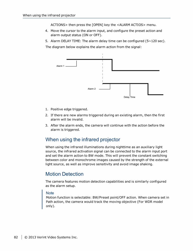
ACTIONS> then press the [OPEN] key the <ALARM ACTIOS> menu.
4. Move the cursor to the alarm input, and configure the preset action andalarm output status (ON or OFF).
5. Alarm DELAY TIME: The alarm delay time can be configured (5~120 sec).
The diagram below explains the alarm action from the signal:
1. Positive edge triggered.
2. If there are new alarms triggered during an existing alarm, then the firstalarm will be invalid.
3. After the alarm ends, the camera will continue with the action before thealarm is triggered.
When using the infrared projectorWhen using the infrared illuminations during nighttime as an auxiliary lightsource, the infrared activation signal can be connected to the alarm input portand set the alarm action to BW mode. This will prevent the constant switchingbetween color and monochrome images caused by the strength of the externallight source, as well as improve sensitivity and avoid image shaking.
Motion DetectionThe camera features motion detection capabilities and is similarly configuredas the alarm setup.
NoteMotion function is selectable: BW/Preset point/OFF action. When camera set inPath action, the camera would track the moving objective (For WDR modelonly).
When using the infrared projector
82 © 2013 Verint Video Systems Inc.
Setting Up Horizontal Pan and Vertical TiltThe following section describes how to configure the Horizontal Pan and VerticalTilt.
Setting Auto Flip<PAN/TILT SETUP> → AUTO FLIP
The auto flipping function will enable the camera to quickly flip 180° in thevertical direction. Objects moving under the camera can be tracked withoutinterruption.
► To activate 180° Auto Flip:1. Press “95” + hold the [PRESET] key for 2 seconds to enter the main menu
screen.
2. Move the cursor to <PAN/TILT SETUP>, and then press the [OPEN] key<PAN/TILT SETUP> menu.
3. Move the cursor to the AUTO FLIP selection and then press the [OPEN] key.
4. Move the joystick up/down to choose ON or OFF.
5. Press the [OPEN] key to confirm the selection or press the [CLOSE] key tocancel selection and exit from the menu screen.
Setting Proportional P/T<PAN/TILT SETUP> → PROPORTIONAL P/T
Proportional P/T enabled to let the camera to adjust the horizontal pan/verticaltilt speed according to the zoom level. When zoomed in, the horizontal andvertical speed will be slowed down so as to keep the image from moving toorapidly.
► To activate the Proportional P/T:1. Press “95” + hold the [PRESET] key for 2 seconds to enter the main menu
screen.
2. Move the cursor to <PAN/TILT SETUP>, and then press the [OPEN] key<PAN/TILT SETUP> menu.
3. Move the cursor to the PROPORTIONAL P/T selection and then press the[OPEN] key.
4. Move the joystick up/down to choose ON or OFF.
5. Press the [OPEN] key to confirm the selection or press the [CLOSE] key tocancel selection and exit from the menu screen.
Chapter 4: Configuring the Nextiva S5500 PTZ Series Properties
© 2013 Verint Video Systems Inc. 83
Setting Scan Range<PAN/TILT SETUP> → SCAN LIMIT STOPS
When the camera scan mode is set to random, frame, or auto, once the scanrange is reached, the camera will turn the other direction.
► To activate a scan range:1. Press “95” + hold the [PRESET] key for 2 seconds to enter the main menu
screen.
2. Move the cursor to <PAN/TILT SETUP>, and then press the [OPEN] key<PAN/TILT SETUP> menu.
3. Move the cursor to the SCAN LIMIT STOPS selection and then press the [OPEN]key.
4. Move the joystick up/down to choose ON or OFF.
5. Press the [OPEN] key to confirm the selection or press the [CLOSE] key tocancel selection and exit from the menu screen.
► To Set the Scan Range:1. Activate the scan range (SCAN LIMIT STOP = ON) and then exit the menu.
2. Set the left limit: use the joystick and move the camera to the left limitposition, then press number key “92” + hold the key for 2 seconds. Thescreen will show: SCAN LEFT LIMIT, and the left limit will be set.
3. Set the right limit: use the joystick and move the camera to the right limitposition, then press number key “93” + hold the key for 2 seconds. Thescreen will show: SCAN RIGHT LIMIT, and the right limit will be set.
Setting Manual Scan Range<PAN/TILT SETUP> → MANUAL LIMIT STOPS
When using the joystick to control the horizontal panning, the camera will stoppanning once it reaches the MANUAL LIMIT STOPS. The scan limit can beconfigured as left and right limit.
► Activate the Manual Scan Range:1. Press “95” + hold the [PRESET] key for 2 seconds to enter the main menu
screen.
2. Move the cursor to <PAN/TILT SETUP>, and then press the [OPEN] key
3. Move the cursor to the MANUAL LIMIT STOPS selection and then press the
Setting Scan Range
84 © 2013 Verint Video Systems Inc.
[OPEN] key.
4. Move the joystick up/down to choose ON or OFF.
5. Press the [OPEN] key to confirm the selection or press the [CLOSE] key tocancel selection and exit from the menu screen.
► To set Set the Manual Scan Range:1. Activate the manual scan range (MANUAL LIMIT STOP = ON) and then exit
the menu.
2. Set the left limit: use the joystick and move the camera to the left limitposition, then press number key “90” + hold the key for 2 seconds. Thescreen will show: MANUAL LEFT LIMIT, and the left limit will be set.
3. Set the right limit: use the joystick and move the camera to the right limitposition, then press number key “91” + hold the key for 2 seconds. Thescreen will show: MANUAL RIGHT LIMIT, and the right limit will be set.
Setting Recover Time<PAN/TILT SETUP> → RECOVER TIME
Under scan mode (auto, frame, random), if the auto patrol and pattern patrolare interrupted from inadvertent keypad controller input, the camera willresume the previous action after a set amount of time. The recovery time canbe configured from 1 to 120 min, and can be disabled (OFF).
► To set the Recovery Time:1. Press “95” + hold the [PRESET] key for 2 seconds to enter the main menu
screen.
2. Move the cursor to <PAN/TILT SETUP>, and then press the [OPEN] key<PAN/TILT SETUP> menu.
3. Move the cursor to the RECOVER TIME selection and then press the [OPEN]key.
4. Move the joystick up/down to set the time.
5. Press the [OPEN] key to confirm the selection or press the [CLOSE] key tocancel selection and exit from the menu screen.
Setting Scan Speed<PAN/TILT SETUP> → SCAN SPEED
Auto, random, and frame scan speed can be configured between 1° ~ 90° /sec,but cannot exceed the MAX SPEED setting.
Chapter 4: Configuring the Nextiva S5500 PTZ Series Properties
© 2013 Verint Video Systems Inc. 85
► To Set the Scan Speed:1. Press “95” + hold the [PRESET] key for 2 seconds to enter the main menu
screen.
2. Move the cursor to <PAN/TILT SETUP>, and then press the [OPEN] key<PAN/TILT SETUP> menu.
3. Move the cursor to the SCAN SPEED selection and then press the [OPEN]key.
4. Move the joystick up/down to set the speed.
5. Press the [OPEN] key to confirm the selection or press the [CLOSE] key tocancel selection and exit from the menu screen.
Setting Stop Time<PAN/TILT SETUP> → STOP TIME
Under random, frame, or auto scan modes, the STOP TIME can be set. Duringscanning, the camera will pause at each stop position from 5 sec to 120 sec.
► To set the Stop Time:1. Press “95” + hold the [PRESET] key for 2 seconds to enter the main menu
screen.
2. Move the cursor to <PAN/TILT SETUP>, and then press the [OPEN] key<PAN/TILT SETUP> menu.
3. Move the cursor to the STOP TIME selection and then press the [OPEN] key.
4. Move the joystick up/down to choose the position, and left/right to set thetime.
5. Press the [OPEN] key to confirm the selection or press the [CLOSE] key tocancel selection and exit from the menu screen.
Setting Max Speed<PAN/TILT SETUP> → MAX SPEED
The max speed for horizontal pan/vertical tilt can be configured between 1° to430° /sec. To lower the amount of noise, it is recommended that a lower speedbe used.
Setting Stop Time
86 © 2013 Verint Video Systems Inc.
► To set the Max Speed:1. Press “95” + hold the [PRESET] key for 2 seconds to enter the main menu
screen.
2. Move the cursor to <PAN/TILT SETUP>, and then press the [OPEN] key<PAN/TILT SETUP> menu.
3. Move the cursor to the MAX SPEED selection and then press the [OPEN] key.
4. Move the joystick up/down to set the speed.
5. Press the [OPEN] key to confirm the selection or press the [CLOSE] key tocancel selection and exit from the menu screen.
Setting Group<PAN/TILT SETUP> → GROUP
For convenience of key press controls, the unit provides 4 sets of preset autopatrol group configurations.
GROUP 1: Press “70”+ [PRESET] key to run first auto patrol group.
GROUP 2: Press “90”+ [PRESET] key to run second auto patrol group.
GROUP 3: Press “91”+ [PRESET] key to run third auto patrol group.
GROUP 4: Press “92”+ [PRESET] key to run fourth auto patrol group.
► To set the Preset Group:1. Press “95” + hold the [PRESET] key for 2 seconds to enter the main menu
screen.
2. Move the cursor to <PAN/TILT SETUP>, and then press the [OPEN] key<PAN/TILT SETUP> menu.
3. Move the cursor to the GROUP selection and then press the [OPEN] key.
4. Move the joystick up/down to set the group.
5. Move the joystick left/right to choose the start position (S), move up/downto set the preset point.
6. Move the joystick left/right to choose the end position (E), move up/down toset the preset point.
7. Press the [OPEN] key to confirm the selection or press the [CLOSE] key tocancel selection and exit from the menu screen.
Setting the Camera Title<CAMERA TITLE> → CAMERA TITLE INPUT
Chapter 4: Configuring the Nextiva S5500 PTZ Series Properties
© 2013 Verint Video Systems Inc. 87
► To set the Title:1. Press “95” + hold the [PRESET] key for 2 seconds to enter the main menu
screen.
2. Move the cursor to <CAMERA TITLE>, and then press the [OPEN] key<CAMERA TITLE> menu.
3. Move the cursor down to CAMERA TITLE INPUT, and then press the key. Usethe joystick up/down to select the character.
4. Move the cursor down to CAMERA TITLE, and then press the key to selecteither ON or OFF. If OFF is selected, then the camera title will not be shown.
5. Press the [OPEN] key to confirm the selection or press the [CLOSE] key tocancel selection and exit from the menu screen.
Setting Up the Presets<PRESET SETUP>
Auto Patrol<PRESET SETUP> → AUTO PATROL
The auto patrol function will continuously scan up to 256 preset positions and isnot limited by the scan range.
► To activate the Auto Patrol:1. Press “95” + hold the [PRESET] key for 2 seconds to enter the main menu
screen.
2. Move the cursor to <PRESET SETUP>, and then press the [OPEN] key<PRESET SETUP> menu.
3. Move the cursor to the AUTO PATROL selection and then press the [OPEN]key.
4. Move the joystick up/down to choose the position, and left/right to set ON orOFF.
5. Press the [OPEN] key to confirm the selection or press the [CLOSE] key tocancel selection and exit from the menu screen.
Preset Speed<PRESET SETUP> → PRESET SPEED
Setting Up the Presets
88 © 2013 Verint Video Systems Inc.
You can modify individual preset speed for individual preset points. Whensetting “MAX” SPEED in preset speed section, the speed is depended on thesetting in SCAN SPEED
► To activate the Preset speed:1. Press “95” + hold the [PRESET] key for 2 seconds to enter the main menu
screen.
2. Move the cursor to <PRESET SETUP>, and then press the [OPEN] key<PRESET SETUP> menu.
3. Move the cursor to the PRESET SPEED selection and then press the [OPEN]key.
4. Move the joystick up/down to choose the position, and left/right to setpreset speed.
5. Press the [OPEN] key to confirm the selection or press the [CLOSE] key tocancel selection and exit from the menu screen.
Title<PRESET SETUP> → <TITLE> → PRESET TITLE INPUT
► To activate the Tilte:Press “95” + hold the [PRESET] key for 2 seconds to enter the main menuscreen.
Move the cursor to <PRESET SETUP>, and then press the [OPEN] key <PRESETSETUP> menu.
Move the cursor to the TITLE selection and then press the [OPEN] key.
Enter TITLE menu then move the joystick up/down to select the preset point.
Move the cursor to the right to enter the title input field. Use the joystickup/down to select the character, and thenmove the cursor left/right to the nextcharacter.
Move the cursor down to the TITLE POSITION, and then press the key to selecteither the UP or DOWN position. UP will show the title at top of the screen, andDOWN will show the title at bottom of the screen.
Preset WD (For WDRmodel only)<PRESET SETUP> → PRESET WD
You can enable WDR function for individual preset point.
NotePRESET WD function only support certain models and support P0~P66preset point only.
Chapter 4: Configuring the Nextiva S5500 PTZ Series Properties
© 2013 Verint Video Systems Inc. 89
► To activate the Preset WD:Press “95” + hold the [PRESET] key for 2 seconds to enter the main menuscreen.
Move the cursor to <PRESET SETUP>, and then press the [OPEN] key <PRESETSETUP> menu.
Move the cursor to the PRESET WD selection and then press the [OPEN] key.
Move the joystick up/down to choose the position(P0~66), and left/right to setOFF, BLC, or WDR.
Press the [OPEN] key to confirm the selection or press the [CLOSE] key tocancel selection and exit from the menu screen.
Preset Motion (For WDRmodel only)<PRESET SETUP> → <PRESET MOTION> → PRESET MOTION
User can enable motion function for individual preset points. You can create andmove up to 4 motion areas for every individual present point.
NotePRESET MOTION function only support certain models and supportP0~P10 preset point only.
► To activate the Preset motion:Press “95” + hold the [PRESET] key for 2 seconds to enter the main menuscreen.
Move the cursor to <PRESET SETUP>, and then press the [OPEN] key <PRESETSETUP> menu.
Move the cursor to the PRESET MOTION selection and then press the [OPEN]key.
Move the joystick up/down to choose the position(P0~10), and left/right to setON, or OFF.
Move the cursor to the MOTION AREA selection and then press the [OPEN] key.
Press the [OPEN] key to confirm the zone #, and then move zone. Screendisplay: MOTION AREA 1 MOVE
Press the [OPEN] key to confirm the zone #, and then go to the setup screen forthe zone size:Screen display: MOTION AREA 1 SIZE
Move the joystick up/down to set the zone size.
press the [CLOSE] key to exit from the menu screen.
Move the joystick up/down to choose the threshold LEVEL selection, andleft/right to set HI, MID or LOW.
Move the joystick up/down to choose the INTERCAL TIME selection, andleft/right to set the time.
Preset Motion (For WDR model only)
90 © 2013 Verint Video Systems Inc.
Press the [OPEN] key to confirm the selection or press the [CLOSE] key tocancel selection and exit from the menu screen.
Setting up the Additional Functions<OTHERS>
Freeze Activity<OTHERS> → FREEZE ACTIVITY
When the camera is in frame, random, auto, or preset scanning modes, thecamera screen can be disabled during movement, and the screen image willonly be shown until the camera reaches the stop point.
► To set Freeze Activity:1. Press “95” + hold the [PRESET] key for 2 seconds to enter the main menu
screen.
2. Move the cursor to <OTHERS>, and then press the [OPEN] key <OTHERS>menu.
3. Move the cursor to the FREEZE ACTIVITY selection and then press the[OPEN] key.
4. Move the joystick up/down to set ON or OFF.
5. Press the [OPEN] key to confirm the selection or press the [CLOSE] key tocancel selection and exit from the menu screen.
Scan Tilt Angle<OTHERS> → SCAN TILT ANGLE
The camera tilt angle can be configured for different application requirements.
► To set the Tilt Angle:1. Press “95” + hold the [PRESET] key for 2 seconds to enter the main menu
screen.
2. Move the cursor to <OTHERS>, and then press the [OPEN] key <OTHERS>
3. Move the cursor to the SCAN TILT ANGLE selection and then press the
Chapter 4: Configuring the Nextiva S5500 PTZ Series Properties
© 2013 Verint Video Systems Inc. 91
[OPEN] key.
4. Move the joystick up/down to set tilt angle (0~92°).
5. Press the [OPEN] key to confirm the selection or press the [CLOSE] key tocancel selection and exit from the menu screen.
Schedule<OTHERS> → <SCHEDULE>
Four sets of schedules can be configured with individual start time, end time,and action mode. The actions include preset(0~32), auto scan, auto patrol 1~4,frame scan, and random scan modes.
► To set a Schedule:1. Press “95” + hold the [PRESET] key for 2 seconds to enter the main menu
screen.
2. Move the cursor to <OTHERS>, and then press the [OPEN] key <OTHERS>menu.
3. Move the cursor to <SCHEDULE>, and then press the [OPEN] key the<SCHEDULE> menu.
4. Move the cursor to WEEK and then press the key. Use the joystick up/down toselect the week and press the key to confirm the selection and quit.
5. Move the cursor to ENABLE and press the key to enter the option. Use thejoystick up/down to set ON or OFF.
6. Press the key to set the start time, end time, and status options.
7. Move the joystick up/down to make the selection.
8. Press the [OPEN] key to confirm the selection or press the [CLOSE] key tocancel selection and exit from the menu screen.
Note1. The Start and End time setup is by the unit of hours. For example, set 0 ->
1 means from 00:00 to 01:59, 2 hours in total.
2. When a schedule mode is ON and within the schedule time interval, thedome will still perform scheduling after power up from abnormal powerlost; regardless of the setting for power on Menu.
Schedule
92 © 2013 Verint Video Systems Inc.
Setting up the System<SYSTEM>
Setting the Week<SYSTEM> → WEEK
► To set the Week:1. Press “95” + hold the [PRESET] key for 2 seconds to enter the main menu
screen.
2. Move the cursor to <SYSTEM>, and then press the [OPEN] key <SYSTEM>menu.
3. Move the cursor to the WEEK selection and then press the [OPEN] key.
4. Move the joystick up/down to set the week.
5. Press the [OPEN] key to confirm the selection or press the [CLOSE] key tocancel selection and exit from the menu screen.
Setting the Time<SYSTEM> → TIME
► To set the Time:1. Press “95” + hold the [PRESET] key for 2 seconds to enter the main menu
screen.
2. Move the cursor to <SYSTEM>, and then press the [OPEN] key <SYSTEM>menu.
3. Move the cursor to the TIME selection and then press the [OPEN] key.
4. Move the joystick up/down to set the time.
5. Press the [OPEN] key to confirm the selection or press the [CLOSE] key tocancel selection and exit from the menu screen.
Setting the Password<SYSTEM> → <PASSWORD>
Chapter 4: Configuring the Nextiva S5500 PTZ Series Properties
© 2013 Verint Video Systems Inc. 93
► To set the Password:1. Press “95” + hold the [PRESET] key for 2 seconds to enter the main menu
screen.
2. Move the cursor to <SYSTEM>, and then press the [OPEN] key <SYSTEM>menu.
3. Move the cursor to <PASSWORD>, and then press the [OPEN] key the<PASSWORD> menu.
4. Move the cursor to PASSWORD ENABLE and press the key to enter theoption. Use the joystick up/down to set ON or OFF.
5. If ON is selected, please enter the password. Press the key to enter thePASSWORD menu.
6. Move the joystick up/down to set the password.
7. Press the [OPEN] key to confirm the selection or press the [CLOSE] key tocancel selection and exit from the menu screen.
Power Up Mode<SYSTEM> → POWER UP
The camera can be configured to different moves after power up:
PARK: The camera will move to the first preset position.
AUTO SCAN: The camera will run auto scan.
FRAME SCAN: The camera will run frame scan.
RANDOM SCAN: The camera will run random scan.
AUTO PATROL: The camera will run auto patrol.
PATTERN 1: The camera will run pattern 1.
BY DEFAULT: The speed dome would return to default setting after poweron. Ex, if the default setting is Auto Scan, the speed dome would run AutoScan after power on.
SCHEDULE: If the default setting is SCHEDULE, the speed dome would runthe path setting in SCHEDULE after power on.
Note1. If Recover Time is enabled, the speed dome would still enable Recover
Time function after power on.
2. When a schedule mode is ON and within the schedule time interval, thedome will still perform scheduling after power up from abnormal powerlost; regardless of the setting for power on Menu.
Power Up Mode
94 © 2013 Verint Video Systems Inc.
► To set the Power Up Mode:1. Press “95” + hold the [PRESET] key for 2 seconds to enter the main menu
screen.
2. Move the cursor to <SYSTEM>, and then press the [OPEN] key <SYSTEM>menu.
3. Move the cursor to the POWER UP selection and then press the [OPEN] key.
4. Move the joystick up/down to set the power up mode.
5. Press the [OPEN] key to confirm the selection or press the [CLOSE] key tocancel selection and exit from the menu screen.
Load Factory Default<SYSTEM> → LOAD FACTORY DEFAULT
► To load the Factory Default:1. Press “95” + hold the [PRESET] key for 2 seconds to enter the main menu
screen.
2. Move the cursor to <SYSTEM>, and then press the [OPEN] key <SYSTEM>menu.
3. Move the cursor to LOAD FACTORY DEFAULT, and then press the [OPEN] keytwice to show the screen: LOAD FACTORY DEFAULT and the setup iscomplete.
NotePlease do not operate keyboard when “*” appear; wait for arrows showing onscreen.
E-FLIP<SYSTEM> → E-FLIP
► To set as E-Flip:1. Press “95” + hold the [PRESET] key for 2 seconds to enter the main menu
screen.
2. Move the cursor to <SYSTEM>, and then press the [OPEN] key <SYSTEM>menu.
3. Move the cursor to the E-FLIP selection and then press the [OPEN] key E-FLIP menu.
4. Move the joystick up/down to set ON or OFF.
5. Press the [OPEN] key to confirm the selection or press the [CLOSE] key tocancel selection and exit from the menu screen.
Chapter 4: Configuring the Nextiva S5500 PTZ Series Properties
© 2013 Verint Video Systems Inc. 95
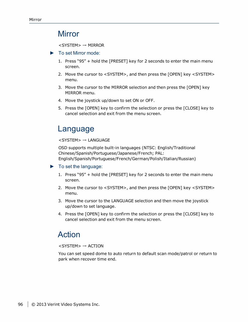
Mirror<SYSTEM> → MIRROR
► To set Mirror mode:1. Press “95” + hold the [PRESET] key for 2 seconds to enter the main menu
screen.
2. Move the cursor to <SYSTEM>, and then press the [OPEN] key <SYSTEM>menu.
3. Move the cursor to the MIRROR selection and then press the [OPEN] keyMIRROR menu.
4. Move the joystick up/down to set ON or OFF.
5. Press the [OPEN] key to confirm the selection or press the [CLOSE] key tocancel selection and exit from the menu screen.
Language<SYSTEM> → LANGUAGE
OSD supports multiple built-in languages (NTSC: English/TraditionalChinese/Spanish/Portuguese/Japanese/French; PAL:English/Spanish/Portuguese/French/German/Polish/Italian/Russian)
► To set the language:1. Press “95” + hold the [PRESET] key for 2 seconds to enter the main menu
screen.
2. Move the cursor to <SYSTEM>, and then press the [OPEN] key <SYSTEM>menu.
3. Move the cursor to the LANGUAGE selection and then move the joystickup/down to set language.
4. Press the [OPEN] key to confirm the selection or press the [CLOSE] key tocancel selection and exit from the menu screen.
Action<SYSTEM> → ACTION
You can set speed dome to auto return to default scan mode/patrol or return topark when recover time end.
Mirror
96 © 2013 Verint Video Systems Inc.
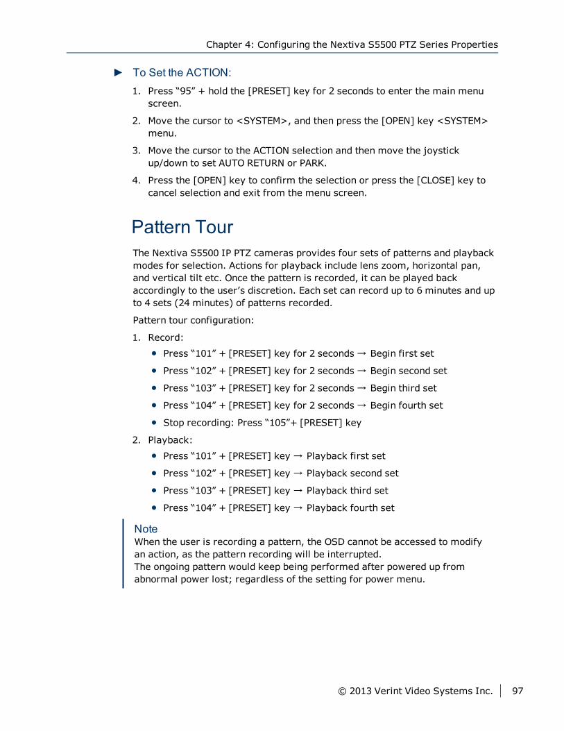
► To Set the ACTION:1. Press “95” + hold the [PRESET] key for 2 seconds to enter the main menu
screen.
2. Move the cursor to <SYSTEM>, and then press the [OPEN] key <SYSTEM>menu.
3. Move the cursor to the ACTION selection and then move the joystickup/down to set AUTO RETURN or PARK.
4. Press the [OPEN] key to confirm the selection or press the [CLOSE] key tocancel selection and exit from the menu screen.
Pattern TourThe Nextiva S5500 IP PTZ cameras provides four sets of patterns and playbackmodes for selection. Actions for playback include lens zoom, horizontal pan,and vertical tilt etc. Once the pattern is recorded, it can be played backaccordingly to the user’s discretion. Each set can record up to 6 minutes and upto 4 sets (24 minutes) of patterns recorded.
Pattern tour configuration:
1. Record:
Press “101” + [PRESET] key for 2 seconds → Begin first set
Press “102” + [PRESET] key for 2 seconds → Begin second set
Press “103” + [PRESET] key for 2 seconds → Begin third set
Press “104” + [PRESET] key for 2 seconds → Begin fourth set
Stop recording: Press “105”+ [PRESET] key
2. Playback:
Press “101” + [PRESET] key → Playback first set
Press “102” + [PRESET] key → Playback second set
Press “103” + [PRESET] key → Playback third set
Press “104” + [PRESET] key → Playback fourth set
NoteWhen the user is recording a pattern, the OSD cannot be accessed to modifyan action, as the pattern recording will be interrupted.The ongoing pattern would keep being performed after powered up fromabnormal power lost; regardless of the setting for power menu.
Chapter 4: Configuring the Nextiva S5500 PTZ Series Properties
© 2013 Verint Video Systems Inc. 97
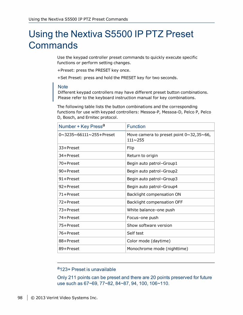
Using the Nextiva S5500 IP PTZ PresetCommands
Use the keypad controller preset commands to quickly execute specificfunctions or perform setting changes.
+Preset: press the PRESET key once.
+Set Preset: press and hold the PRESET key for two seconds.
NoteDifferent keypad controllers may have different preset button combinations.Please refer to the keyboard instruction manual for key combinations.
The following table lists the button combinations and the correspondingfunctions for use with keypad controllers: Messoa-P, Messoa-D, Pelco P, PelcoD, Bosch, and Ernitec protocol.
Number + Key Pressa Function
0~3235~66111~255+Preset Move camera to preset point 0~32,35~66,111~255
33+Preset Flip
34+Preset Return to origin
70+Preset Begin auto patrol–Group1
90+Preset Begin auto patrol–Group2
91+Preset Begin auto patrol–Group3
92+Preset Begin auto patrol–Group4
71+Preset Backlight compensation ON
72+Preset Backlight compensation OFF
73+Preset White balance–one push
74+Preset Focus–one push
75+Preset Show software version
76+Preset Self test
88+Preset Color mode (daytime)
89+Preset Monochrome mode (nighttime)
a123+ Preset is unavailable
Only 211 points can be preset and there are 20 points preserved for futureuse such as 67~69, 77~82, 84~87, 94, 100, 106~110.
Using the Nextiva S5500 IP PTZ Preset Commands
98 © 2013 Verint Video Systems Inc.
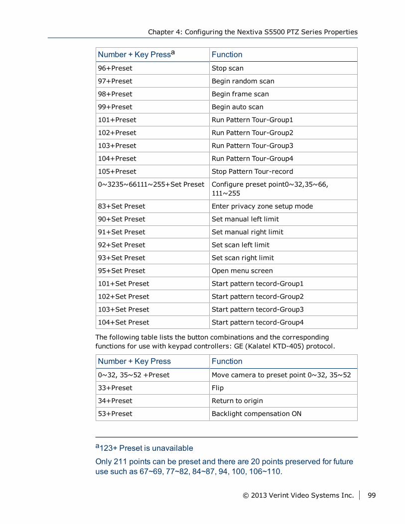
Number + Key Pressa Function
96+Preset Stop scan
97+Preset Begin random scan
98+Preset Begin frame scan
99+Preset Begin auto scan
101+Preset Run Pattern Tour-Group1
102+Preset Run Pattern Tour-Group2
103+Preset Run Pattern Tour-Group3
104+Preset Run Pattern Tour-Group4
105+Preset Stop Pattern Tour-record
0~3235~66111~255+Set Preset Configure preset point0~32,35~66,111~255
83+Set Preset Enter privacy zone setup mode
90+Set Preset Set manual left limit
91+Set Preset Set manual right limit
92+Set Preset Set scan left limit
93+Set Preset Set scan right limit
95+Set Preset Open menu screen
101+Set Preset Start pattern tecord-Group1
102+Set Preset Start pattern tecord-Group2
103+Set Preset Start pattern tecord-Group3
104+Set Preset Start pattern tecord-Group4
The following table lists the button combinations and the correspondingfunctions for use with keypad controllers: GE (Kalatel KTD-405) protocol.
Number + Key Press Function
0~32, 35~52 +Preset Move camera to preset point 0~32, 35~52
33+Preset Flip
34+Preset Return to origin
53+Preset Backlight compensation ON
a123+ Preset is unavailable
Only 211 points can be preset and there are 20 points preserved for futureuse such as 67~69, 77~82, 84~87, 94, 100, 106~110.
Chapter 4: Configuring the Nextiva S5500 PTZ Series Properties
© 2013 Verint Video Systems Inc. 99
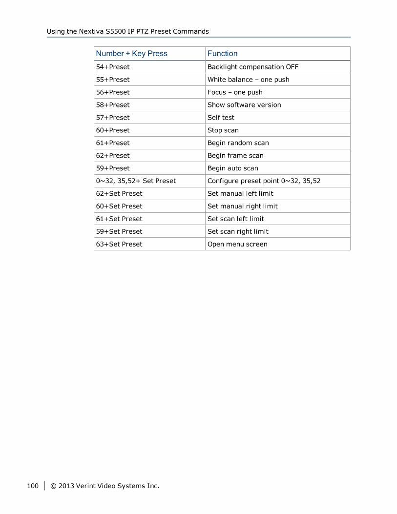
Number + Key Press Function
54+Preset Backlight compensation OFF
55+Preset White balance – one push
56+Preset Focus – one push
58+Preset Show software version
57+Preset Self test
60+Preset Stop scan
61+Preset Begin random scan
62+Preset Begin frame scan
59+Preset Begin auto scan
0~32, 35,52+ Set Preset Configure preset point 0~32, 35,52
62+Set Preset Set manual left limit
60+Set Preset Set manual right limit
61+Set Preset Set scan left limit
59+Set Preset Set scan right limit
63+Set Preset Open menu screen
Using the Nextiva S5500 IP PTZ Preset Commands
100 © 2013 Verint Video Systems Inc.
The following topics are discussed:
DIP Switch Settings 103
SW1 PTZ Address Setup 104
Communication protocol / Baud rate / Terminal resistance 108
Technical Specifications 108
Appendix 5Appendix 5: Technical Specifications
The sections describes the DIP switch settings and the technical specificationsfor the Nextiva S5500 PTZ series.

Appendix 5: Technical Specifications
102 © 2013 Verint Video Systems Inc.
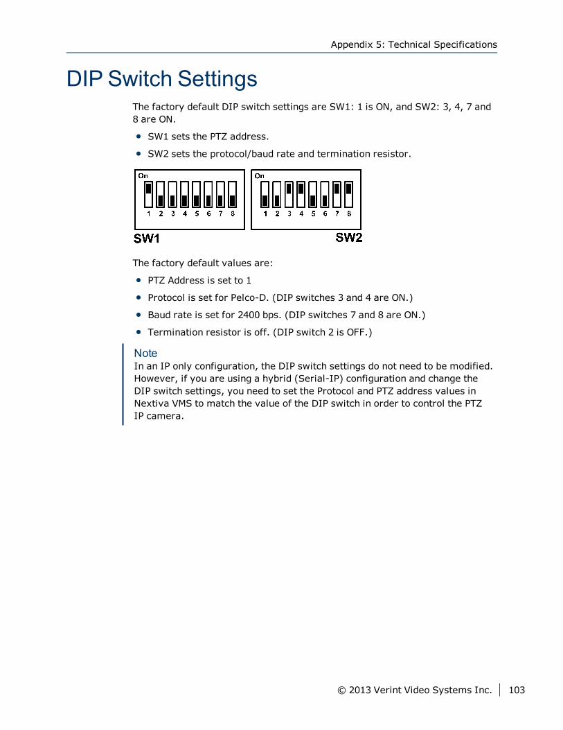
DIP Switch SettingsThe factory default DIP switch settings are SW1: 1 is ON, and SW2: 3, 4, 7 and8 are ON.
SW1 sets the PTZ address.
SW2 sets the protocol/baud rate and termination resistor.
The factory default values are:
PTZ Address is set to 1
Protocol is set for Pelco-D. (DIP switches 3 and 4 are ON.)
Baud rate is set for 2400 bps. (DIP switches 7 and 8 are ON.)
Termination resistor is off. (DIP switch 2 is OFF.)
NoteIn an IP only configuration, the DIP switch settings do not need to be modified.However, if you are using a hybrid (Serial-IP) configuration and change theDIP switch settings, you need to set the Protocol and PTZ address values inNextiva VMS to match the value of the DIP switch in order to control the PTZIP camera.
Appendix 5: Technical Specifications
© 2013 Verint Video Systems Inc. 103
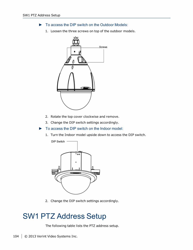
► To access the DIP switch on the Outdoor Models:1. Loosen the three screws on top of the outdoor models.
2. Rotate the top cover clockwise and remove.
3. Change the DIP switch settings accordingly.
► To access the DIP switch on the Indoor model:1. Turn the Indoor model upside down to access the DIP switch.
2. Change the DIP switch settings accordingly.
SW1 PTZ Address SetupThe following table lists the PTZ address setup.
SW1 PTZ Address Setup
104 © 2013 Verint Video Systems Inc.
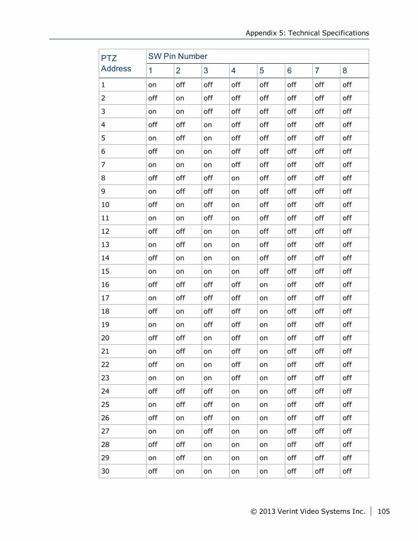
PTZAddress
SW Pin Number
1 2 3 4 5 6 7 8
1 on off off off off off off off
2 off on off off off off off off
3 on on off off off off off off
4 off off on off off off off off
5 on off on off off off off off
6 off on on off off off off off
7 on on on off off off off off
8 off off off on off off off off
9 on off off on off off off off
10 off on off on off off off off
11 on on off on off off off off
12 off off on on off off off off
13 on off on on off off off off
14 off on on on off off off off
15 on on on on off off off off
16 off off off off on off off off
17 on off off off on off off off
18 off on off off on off off off
19 on on off off on off off off
20 off off on off on off off off
21 on off on off on off off off
22 off on on off on off off off
23 on on on off on off off off
24 off off off on on off off off
25 on off off on on off off off
26 off on off on on off off off
27 on on off on on off off off
28 off off on on on off off off
29 on off on on on off off off
30 off on on on on off off off
Appendix 5: Technical Specifications
© 2013 Verint Video Systems Inc. 105
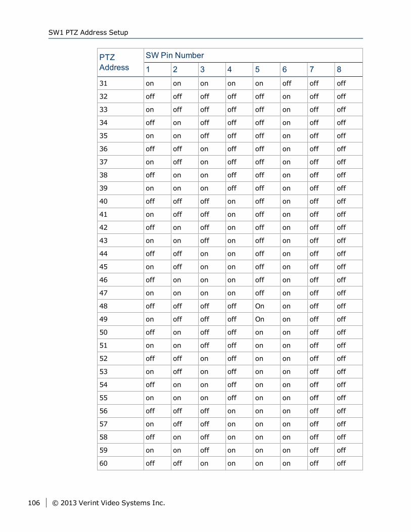
PTZAddress
SW Pin Number
1 2 3 4 5 6 7 8
31 on on on on on off off off
32 off off off off off on off off
33 on off off off off on off off
34 off on off off off on off off
35 on on off off off on off off
36 off off on off off on off off
37 on off on off off on off off
38 off on on off off on off off
39 on on on off off on off off
40 off off off on off on off off
41 on off off on off on off off
42 off on off on off on off off
43 on on off on off on off off
44 off off on on off on off off
45 on off on on off on off off
46 off on on on off on off off
47 on on on on off on off off
48 off off off off On on off off
49 on off off off On on off off
50 off on off off on on off off
51 on on off off on on off off
52 off off on off on on off off
53 on off on off on on off off
54 off on on off on on off off
55 on on on off on on off off
56 off off off on on on off off
57 on off off on on on off off
58 off on off on on on off off
59 on on off on on on off off
60 off off on on on on off off
SW1 PTZ Address Setup
106 © 2013 Verint Video Systems Inc.
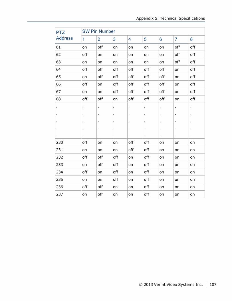
PTZAddress
SW Pin Number
1 2 3 4 5 6 7 8
61 on off on on on on off off
62 off on on on on on off off
63 on on on on on on off off
64 off off off off off off on off
65 on off off off off off on off
66 off on off off off off on off
67 on on off off off off on off
68 off off on off off off on off
.
.
.
.
.
.
.
.
.
.
.
.
.
.
.
.
.
.
.
.
.
.
.
.
.
.
.
.
.
.
.
.
.
.
.
.
.
.
.
.
.
.
.
.
.
230 off on on off off on on on
231 on on on off off on on on
232 off off off on off on on on
233 on off off on off on on on
234 off on off on off on on on
235 on on off on off on on on
236 off off on on off on on on
237 on off on on off on on on
Appendix 5: Technical Specifications
© 2013 Verint Video Systems Inc. 107
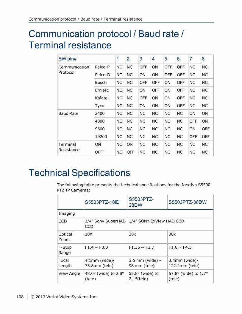
Communication protocol / Baud rate /Terminal resistance
SW pin# 1 2 3 4 5 6 7 8
CommunicationProtocol
Pelco-P NC NC OFF ON OFF OFF NC NC
Pelco-D NC NC ON ON OFF OFF NC NC
Bosch NC NC OFF OFF ON OFF NC NC
Ernitec NC NC ON OFF ON OFF NC NC
Kalatel NC NC OFF ON ON OFF NC NC
Tyco NC NC ON ON ON OFF NC NC
Baud Rate 2400 NC NC NC NC NC NC ON ON
4800 NC NC NC NC NC NC OFF ON
9600 NC NC NC NC NC NC ON OFF
19200 NC NC NC NC NC NC OFF OFF
TerminalResistance
ON NC ON NC NC NC NC NC NC
OFF NC OFF NC NC NC NC NC NC
Technical SpecificationsThe following table presents the technical specifications for the Nextiva S5500PTZ IP Cameras:
S5503PTZ-18ID S5503PTZ-28DW S5503PTZ-36DW
Imaging
CCD 1/4" Sony SuperHADCCD
1/4" SONY ExView HAD CCD
OpticalZoom
18X 28x 36x
F-StopRange
F1.4 ~ F3.0 F1.35 ~ F3.7 F1.6 ~ F4.5
FocalLength
4.1mm (wide)-73.8mm (tele)
3.5 mm (wide) -98 mm (tele)
3.4mm (wide)-122.4mm (tele)
View Angle 48.0° (wide) to 2.8°(tele)
55.8° (wide) to2.1°(tele)
57.8° (wide) to 1.7°(tele)
Communication protocol / Baud rate / Terminal resistance
108 © 2013 Verint Video Systems Inc.
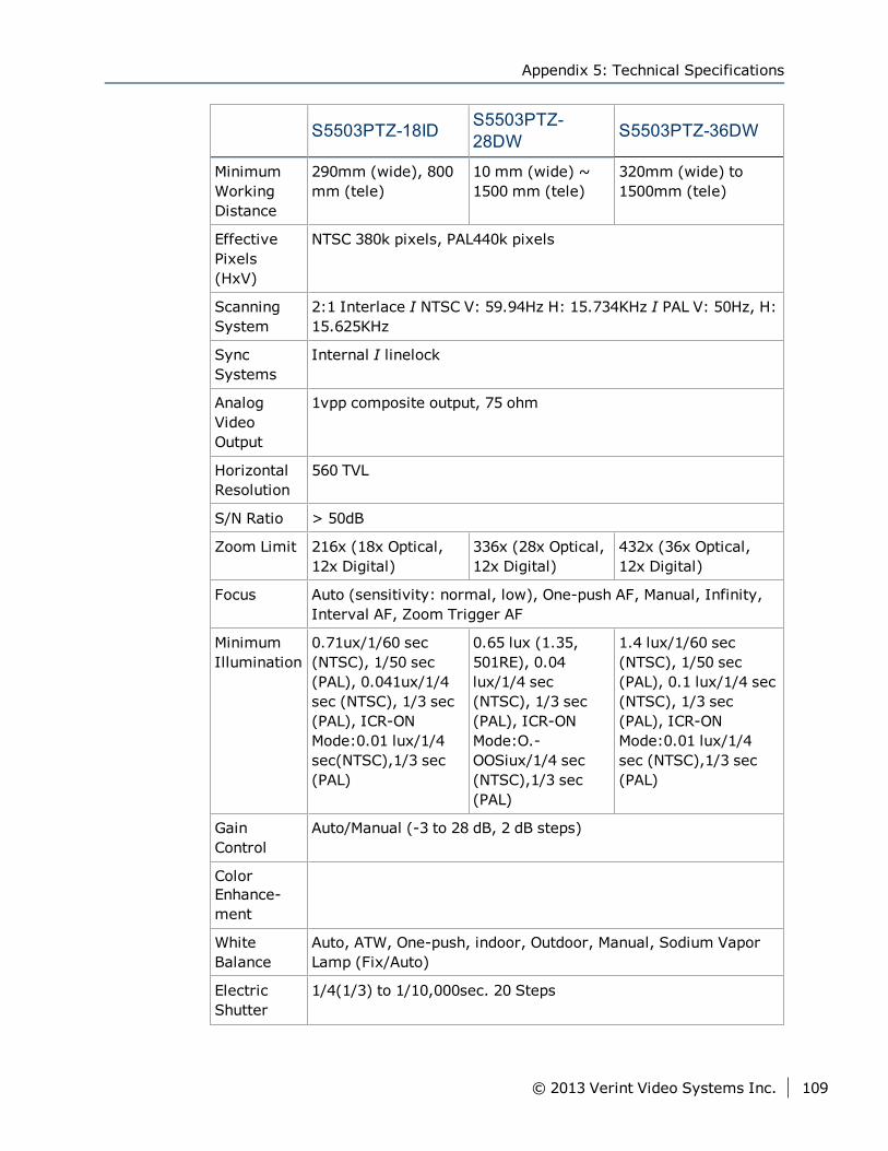
S5503PTZ-18ID S5503PTZ-28DW S5503PTZ-36DW
MinimumWorkingDistance
290mm (wide), 800mm (tele)
10 mm (wide) ~1500 mm (tele)
320mm (wide) to1500mm (tele)
EffectivePixels(HxV)
NTSC 380k pixels, PAL440k pixels
ScanningSystem
2:1 Interlace I NTSC V: 59.94Hz H: 15.734KHz I PAL V: 50Hz, H:15.625KHz
SyncSystems
Internal I linelock
AnalogVideoOutput
1vpp composite output, 75 ohm
HorizontalResolution
560 TVL
S/N Ratio > 50dB
Zoom Limit 216x (18x Optical,12x Digital)
336x (28x Optical,12x Digital)
432x (36x Optical,12x Digital)
Focus Auto (sensitivity: normal, low), One-push AF, Manual, Infinity,Interval AF, Zoom Trigger AF
MinimumIllumination
0.71ux/1/60 sec(NTSC), 1/50 sec(PAL), 0.041ux/1/4sec (NTSC), 1/3 sec(PAL), ICR-ONMode:0.01 lux/1/4sec(NTSC),1/3 sec(PAL)
0.65 lux (1.35,501RE), 0.04lux/1/4 sec(NTSC), 1/3 sec(PAL), ICR-ONMode:O.-OOSiux/1/4 sec(NTSC),1/3 sec(PAL)
1.4 lux/1/60 sec(NTSC), 1/50 sec(PAL), 0.1 lux/1/4 sec(NTSC), 1/3 sec(PAL), ICR-ONMode:0.01 lux/1/4sec (NTSC),1/3 sec(PAL)
GainControl
Auto/Manual (-3 to 28 dB, 2 dB steps)
ColorEnhance-ment
WhiteBalance
Auto, ATW, One-push, indoor, Outdoor, Manual, Sodium VaporLamp (Fix/Auto)
ElectricShutter
1/4(1/3) to 1/10,000sec. 20 Steps
Appendix 5: Technical Specifications
© 2013 Verint Video Systems Inc. 109
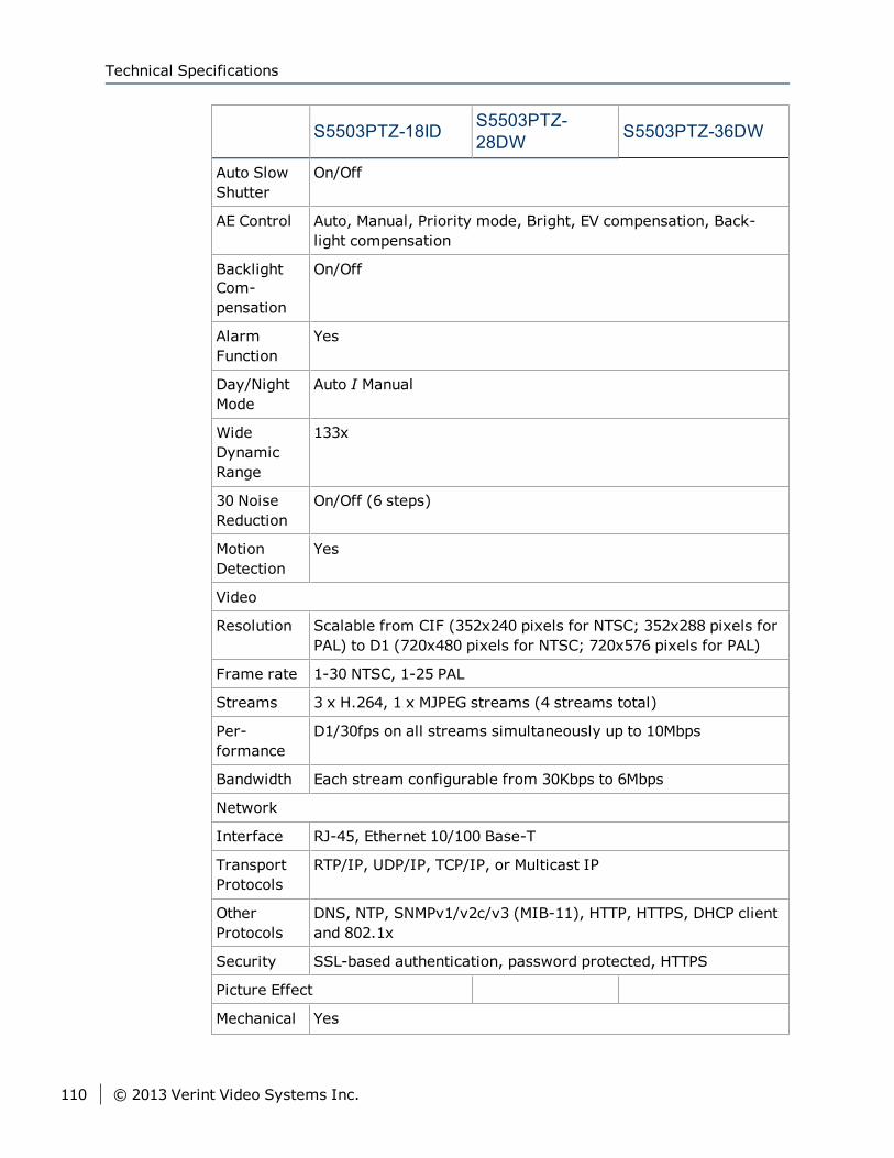
S5503PTZ-18ID S5503PTZ-28DW S5503PTZ-36DW
Auto SlowShutter
On/Off
AE Control Auto, Manual, Priority mode, Bright, EV compensation, Back-light compensation
BacklightCom-pensation
On/Off
AlarmFunction
Yes
Day/NightMode
Auto I Manual
WideDynamicRange
133x
30 NoiseReduction
On/Off (6 steps)
MotionDetection
Yes
Video
Resolution Scalable from CIF (352x240 pixels for NTSC; 352x288 pixels forPAL) to D1 (720x480 pixels for NTSC; 720x576 pixels for PAL)
Frame rate 1-30 NTSC, 1-25 PAL
Streams 3 x H.264, 1 x MJPEG streams (4 streams total)
Per-formance
D1/30fps on all streams simultaneously up to 10Mbps
Bandwidth Each stream configurable from 30Kbps to 6Mbps
Network
Interface RJ-45, Ethernet 10/100 Base-T
TransportProtocols
RTP/IP, UDP/IP, TCP/IP, or Multicast IP
OtherProtocols
DNS, NTP, SNMPv1/v2c/v3 (MIB-11), HTTP, HTTPS, DHCP clientand 802.1x
Security SSL-based authentication, password protected, HTTPS
Picture Effect
Mechanical Yes
Technical Specifications
110 © 2013 Verint Video Systems Inc.
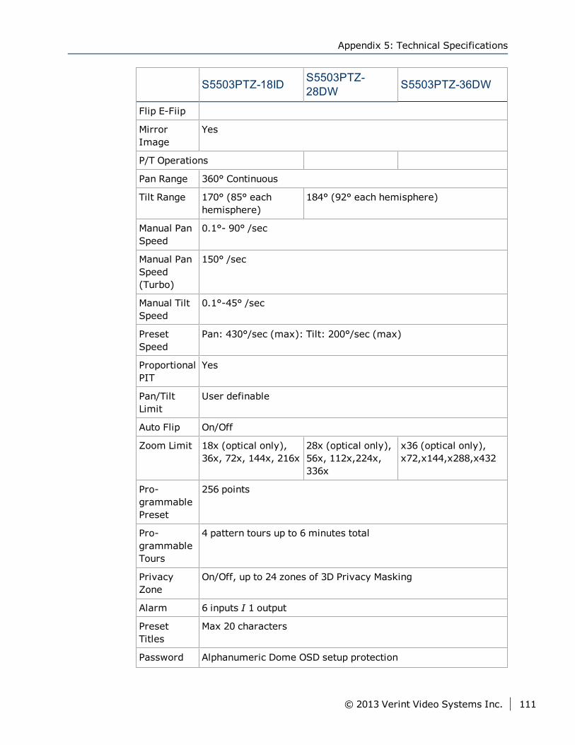
S5503PTZ-18ID S5503PTZ-28DW S5503PTZ-36DW
Flip E-Fiip
MirrorImage
Yes
P/T Operations
Pan Range 360° Continuous
Tilt Range 170° (85° eachhemisphere)
184° (92° each hemisphere)
Manual PanSpeed
0.1°- 90° /sec
Manual PanSpeed(Turbo)
150° /sec
Manual TiltSpeed
0.1°-45° /sec
PresetSpeed
Pan: 430°/sec (max): Tilt: 200°/sec (max)
ProportionalPIT
Yes
Pan/TiltLimit
User definable
Auto Flip On/Off
Zoom Limit 18x (optical only),36x, 72x, 144x, 216x
28x (optical only),56x, 112x,224x,336x
x36 (optical only),x72,x144,x288,x432
Pro-grammablePreset
256 points
Pro-grammableTours
4 pattern tours up to 6 minutes total
PrivacyZone
On/Off, up to 24 zones of 3D Privacy Masking
Alarm 6 inputs I 1 output
PresetTitles
Max 20 characters
Password Alphanumeric Dome OSD setup protection
Appendix 5: Technical Specifications
© 2013 Verint Video Systems Inc. 111
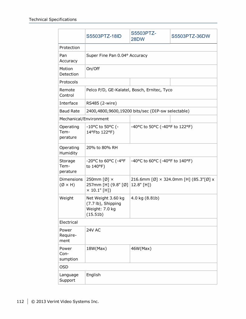
S5503PTZ-18ID S5503PTZ-28DW S5503PTZ-36DW
Protection
PanAccuracy
Super Fine Pan 0.04° Accuracy
MotionDetection
On/Off
Protocols
RemoteControl
Pelco P/D, GE-Kalatel, Bosch, Ernitec, Tyco
Interface RS485 (2-wire)
Baud Rate 2400,4800,9600,19200 bits/sec (DIP-sw selectable)
Mechanical/Environment
OperatingTem-perature
-10°C to 50°C (-14°Fto 122°F)
-40°C to 50°C (-40°F to 122°F)
OperatingHumidity
20% to 80% RH
StorageTem-perature
-20°C to 60°C (-4°Fto 140°F)
-40°C to 60°C (-40°F to 140°F)
Dimensions(Ø × H)
250mm [Ø] ×257mm [H] (9.8" [Ø]× 10.1" [H])
216.6mm [Ø] × 324.0mm [H] (85.3"[Ø] x12.8" [H])
Weight Net Weight 3.60 kg(7.7 lb), ShippingWeight: 7.0 kg(15.51b)
4.0 kg (8.81b)
Electrical
PowerRequire-ment
24V AC
PowerCon-sumption
18W(Max) 46W(Max)
OSD
LanguageSupport
English
Technical Specifications
112 © 2013 Verint Video Systems Inc.
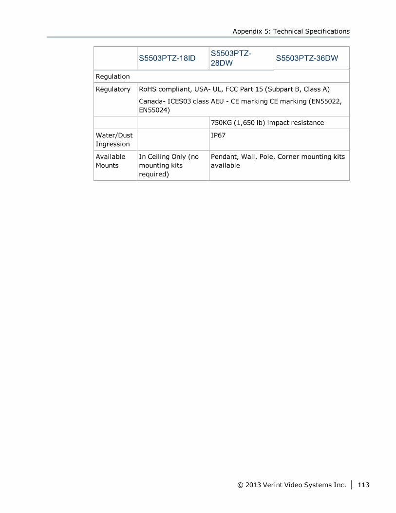
S5503PTZ-18ID S5503PTZ-28DW S5503PTZ-36DW
Regulation
Regulatory RoHS compliant, USA- UL, FCC Part 15 (Subpart B, Class A)
Canada- ICES03 class AEU - CE marking CE marking (EN55022,EN55024)
750KG (1,650 lb) impact resistance
Water/DustIngression
IP67
AvailableMounts
In Ceiling Only (nomounting kitsrequired)
Pendant, Wall, Pole, Corner mounting kitsavailable
Appendix 5: Technical Specifications
© 2013 Verint Video Systems Inc. 113
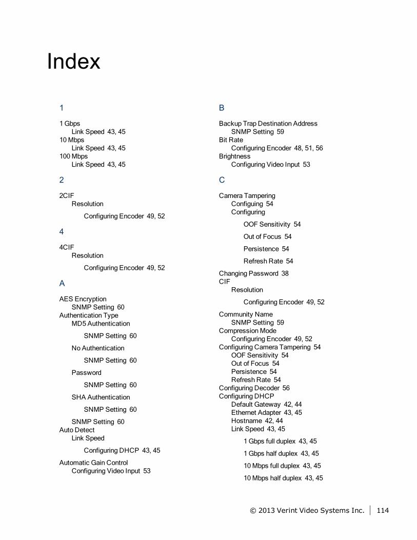
Index
1
1GbpsLink Speed 43, 45
10MbpsLink Speed 43, 45
100MbpsLink Speed 43, 45
2
2CIFResolution
Configuring Encoder 49, 52
4
4CIFResolution
Configuring Encoder 49, 52
A
AES EncryptionSNMP Setting 60
Authentication TypeMD5 Authentication
SNMP Setting 60
No Authentication
SNMP Setting 60
Password
SNMP Setting 60
SHA Authentication
SNMP Setting 60
SNMP Setting 60Auto Detect
Link Speed
Configuring DHCP 43, 45
Automatic Gain ControlConfiguring Video Input 53
B
Backup Trap Destination AddressSNMP Setting 59
Bit RateConfiguring Encoder 48, 51, 56
BrightnessConfiguring Video Input 53
C
Camera TamperingConfiguing 54Configuring
OOF Sensitivity 54
Out of Focus 54
Persistence 54
Refresh Rate 54
Changing Password 38CIF
Resolution
Configuring Encoder 49, 52
Community NameSNMP Setting 59
CompressionModeConfiguring Encoder 49, 52
Configuring Camera Tampering 54OOF Sensitivity 54Out of Focus 54Persistence 54Refresh Rate 54
Configuring Decoder 56Configuring DHCP
Default Gateway 42, 44Ethernet Adapter 43, 45Hostname 42, 44Link Speed 43, 45
1Gbps full duplex 43, 45
1Gbps half duplex 43, 45
10Mbps full duplex 43, 45
10Mbps half duplex 43, 45
© 2013 Verint Video Systems Inc. 114
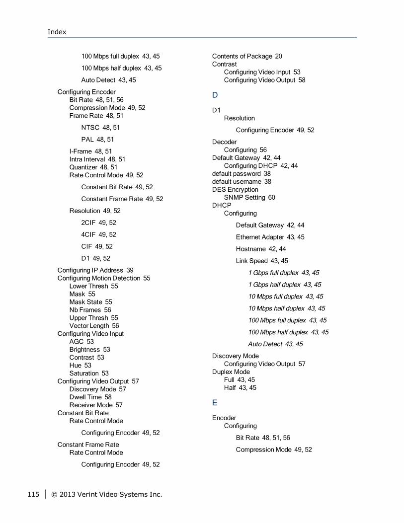
100Mbps full duplex 43, 45
100Mbps half duplex 43, 45
Auto Detect 43, 45
Configuring EncoderBit Rate 48, 51, 56CompressionMode 49, 52FrameRate 48, 51
NTSC 48, 51
PAL 48, 51
I-Frame 48, 51Intra Interval 48, 51Quantizer 48, 51Rate Control Mode 49, 52
Constant Bit Rate 49, 52
Constant FrameRate 49, 52
Resolution 49, 52
2CIF 49, 52
4CIF 49, 52
CIF 49, 52
D1 49, 52
Configuring IP Address 39ConfiguringMotion Detection 55
Lower Thresh 55Mask 55Mask State 55Nb Frames 56Upper Thresh 55Vector Length 56
Configuring Video InputAGC 53Brightness 53Contrast 53Hue 53Saturation 53
Configuring VideoOutput 57Discovery Mode 57Dwell Time 58Receiver Mode 57
Constant Bit RateRate Control Mode
Configuring Encoder 49, 52
Constant FrameRateRate Control Mode
Configuring Encoder 49, 52
Contents of Package 20Contrast
Configuring Video Input 53Configuring VideoOutput 58
D
D1Resolution
Configuring Encoder 49, 52
DecoderConfiguring 56
Default Gateway 42, 44Configuring DHCP 42, 44
default password 38default username 38DES Encryption
SNMP Setting 60DHCP
Configuring
Default Gateway 42, 44
Ethernet Adapter 43, 45
Hostname 42, 44
Link Speed 43, 45
1Gbps full duplex 43, 45
1Gbps half duplex 43, 45
10Mbps full duplex 43, 45
10Mbps half duplex 43, 45
100Mbps full duplex 43, 45
100Mbps half duplex 43, 45
Auto Detect 43, 45
Discovery ModeConfiguring VideoOutput 57
Duplex ModeFull 43, 45Half 43, 45
E
EncoderConfiguring
Bit Rate 48, 51, 56
CompressionMode 49, 52
Index
115 © 2013 Verint Video Systems Inc.
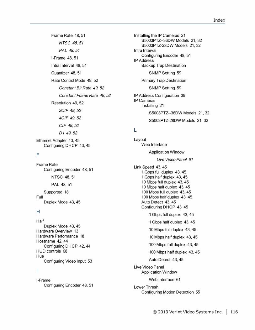
FrameRate 48, 51
NTSC 48, 51
PAL 48, 51
I-Frame 48, 51
Intra Interval 48, 51
Quantizer 48, 51
Rate Control Mode 49, 52
Constant Bit Rate 49, 52
Constant FrameRate 49, 52
Resolution 49, 52
2CIF 49, 52
4CIF 49, 52
CIF 49, 52
D1 49, 52
Ethernet Adapter 43, 45Configuring DHCP 43, 45
F
FrameRateConfiguring Encoder 48, 51
NTSC 48, 51
PAL 48, 51
Supported 18Full
Duplex Mode 43, 45
H
HalfDuplex Mode 43, 45
Hardware Overview 13Hardware Performance 18Hostname 42, 44
Configuring DHCP 42, 44HUD controls 68Hue
Configuring Video Input 53
I
I-FrameConfiguring Encoder 48, 51
Installing the IP Cameras 21S5003PTZ--36DW Models 21, 32S5003PTZ-28DW Models 21, 32
Intra IntervalConfiguring Encoder 48, 51
IP AddressBackup Trap Destination
SNMP Setting 59
Primary Trap Destination
SNMP Setting 59
IP Address Configuration 39IP Cameras
Installing 21
S5003PTZ--36DW Models 21, 32
S5003PTZ-28DW Models 21, 32
L
LayoutWeb Interface
ApplicationWindow
Live Video Panel 61
Link Speed 43, 451Gbps full duplex 43, 451Gbps half duplex 43, 4510Mbps full duplex 43, 4510Mbps half duplex 43, 45100Mbps full duplex 43, 45100Mbps half duplex 43, 45Auto Detect 43, 45Configuring DHCP 43, 45
1Gbps full duplex 43, 45
1Gbps half duplex 43, 45
10Mbps full duplex 43, 45
10Mbps half duplex 43, 45
100Mbps full duplex 43, 45
100Mbps half duplex 43, 45
Auto Detect 43, 45
Live Video PanelApplicationWindow
Web Interface 61
Lower ThreshConfiguringMotion Detection 55
Index
© 2013 Verint Video Systems Inc. 116
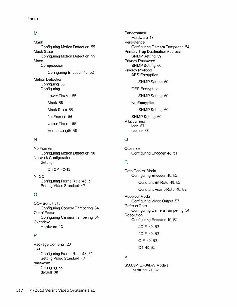
M
MaskConfiguringMotion Detection 55
Mask StateConfiguringMotion Detection 55
ModeCompression
Configuring Encoder 49, 52
Motion DetectionConfiguing 55Configuring
Lower Thresh 55
Mask 55
Mask State 55
Nb Frames 56
Upper Thresh 55
Vector Length 56
N
Nb FramesConfiguringMotion Detection 56
Network ConfigurationSetting
DHCP 42-45
NTSCConfiguring FrameRate 48, 51Setting Video Standard 47
O
OOF SensitivityConfiguring Camera Tampering 54
Out of FocusConfiguring Camera Tampering 54
OverviewHardware 13
P
Package Contents 20PAL
Configuring FrameRate 48, 51Setting Video Standard 47
passwordChanging 38default 38
PerformanceHardware 18
PersistenceConfiguring Camera Tampering 54
Primary Trap Destination AddressSNMP Setting 59
Privacy PasswordSNMP Setting 60
Privacy ProtocolAES Encryption
SNMP Setting 60
DES Encryption
SNMP Setting 60
No Encryption
SNMP Setting 60
SNMP Setting 60PTZ camera
icon 67toolbar 68
Q
QuantizerConfiguring Encoder 48, 51
R
Rate Control ModeConfiguring Encoder 49, 52
Constant Bit Rate 49, 52
Constant FrameRate 49, 52
Receiver ModeConfiguring VideoOutput 57
Refresh RateConfiguring Camera Tampering 54
ResolutionConfiguring Encoder 49, 52
2CIF 49, 52
4CIF 49, 52
CIF 49, 52
D1 49, 52
S
S5003PTZ--36DW ModelsInstalling 21, 32
Index
117 © 2013 Verint Video Systems Inc.
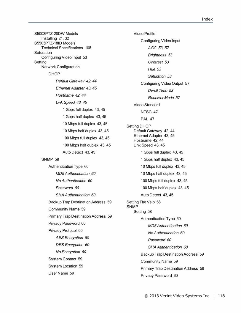
S5003PTZ-28DW ModelsInstalling 21, 32
S5503PTZ-18ID ModelsTechnical Specifications 108
SaturationConfiguring Video Input 53
SettingNetwork Configuration
DHCP
Default Gateway 42, 44
Ethernet Adapter 43, 45
Hostname 42, 44
Link Speed 43, 45
1Gbps full duplex 43, 45
1Gbps half duplex 43, 45
10Mbps full duplex 43, 45
10Mbps half duplex 43, 45
100Mbps full duplex 43, 45
100Mbps half duplex 43, 45
Auto Detect 43, 45
SNMP 58
Authentication Type 60
MD5Authentication 60
No Authentication 60
Password 60
SHA Authentication 60
Backup Trap Destination Address 59
Community Name 59
Primary Trap Destination Address 59
Privacy Password 60
Privacy Protocol 60
AES Encryption 60
DES Encryption 60
No Encryption 60
System Contact 59
System Location 59
User Name 59
Video Profile
Configuring Video Input
AGC 53, 57
Brightness 53
Contrast 53
Hue 53
Saturation 53
Configuring VideoOutput 57
Dwell Time 58
Receiver Mode 57
Video Standard
NTSC 47
PAL 47
Setting DHCPDefault Gateway 42, 44Ethernet Adapter 43, 45Hostname 42, 44Link Speed 43, 45
1Gbps full duplex 43, 45
1Gbps half duplex 43, 45
10Mbps full duplex 43, 45
10Mbps half duplex 43, 45
100Mbps full duplex 43, 45
100Mbps half duplex 43, 45
Auto Detect 43, 45
Setting The Vsip 58SNMP
Setting 58
Authentication Type 60
MD5Authentication 60
No Authentication 60
Password 60
SHA Authentication 60
Backup Trap Destination Address 59
Community Name 59
Primary Trap Destination Address 59
Privacy Password 60
Index
© 2013 Verint Video Systems Inc. 118
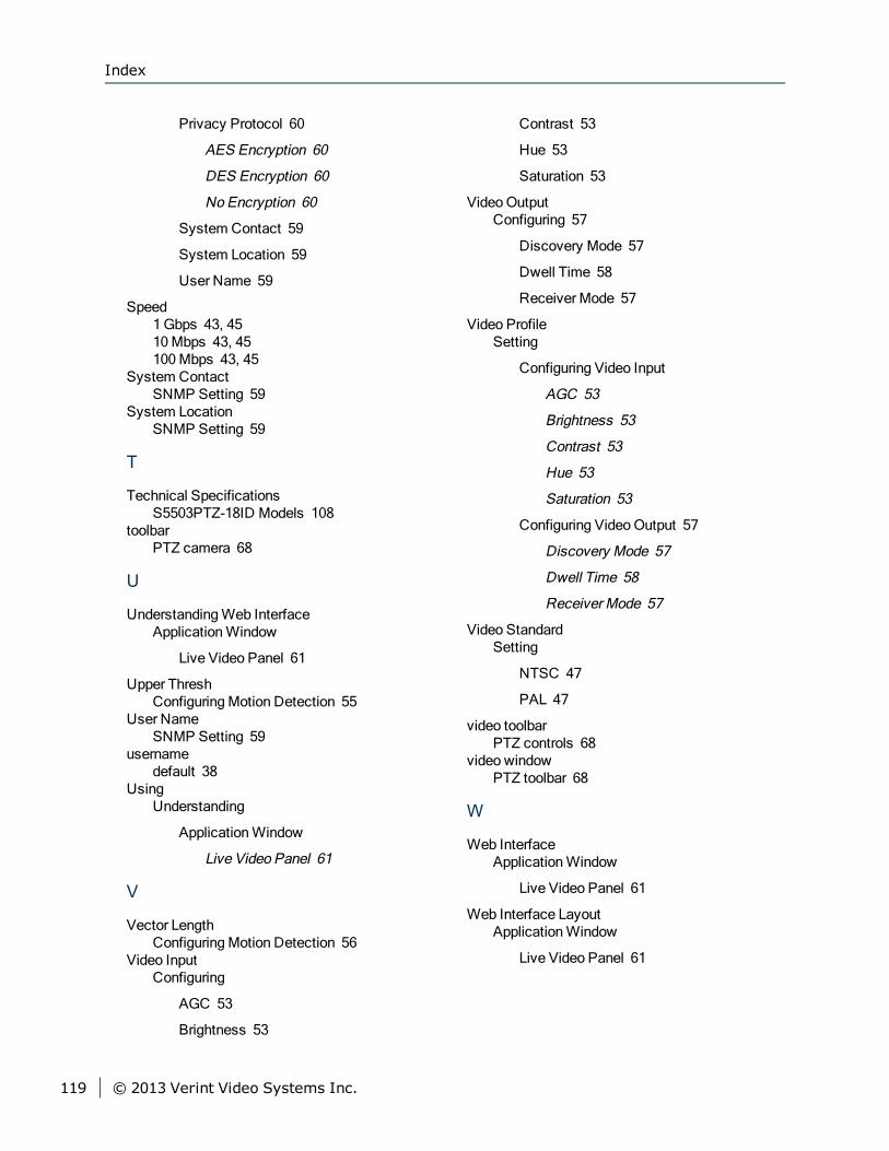
Privacy Protocol 60
AES Encryption 60
DES Encryption 60
No Encryption 60
System Contact 59
System Location 59
User Name 59
Speed1Gbps 43, 4510Mbps 43, 45100Mbps 43, 45
System ContactSNMP Setting 59
System LocationSNMP Setting 59
T
Technical SpecificationsS5503PTZ-18ID Models 108
toolbarPTZ camera 68
U
UnderstandingWeb InterfaceApplicationWindow
Live Video Panel 61
Upper ThreshConfiguringMotion Detection 55
User NameSNMP Setting 59
usernamedefault 38
UsingUnderstanding
ApplicationWindow
Live Video Panel 61
V
Vector LengthConfiguringMotion Detection 56
Video InputConfiguring
AGC 53
Brightness 53
Contrast 53
Hue 53
Saturation 53
VideoOutputConfiguring 57
Discovery Mode 57
Dwell Time 58
Receiver Mode 57
Video ProfileSetting
Configuring Video Input
AGC 53
Brightness 53
Contrast 53
Hue 53
Saturation 53
Configuring VideoOutput 57
Discovery Mode 57
Dwell Time 58
Receiver Mode 57
Video StandardSetting
NTSC 47
PAL 47
video toolbarPTZ controls 68
video windowPTZ toolbar 68
W
Web InterfaceApplicationWindow
Live Video Panel 61
Web Interface LayoutApplicationWindow
Live Video Panel 61
Index
119 © 2013 Verint Video Systems Inc.

For more information, please visit us at http://www.verint.com/solutions/video-situation-intelligence/index.html
Americas: [email protected]
EMEA: [email protected]
APAC: [email protected]
All other trademarks and product names are the property of their respective owners.
The information in this document may be superseded by subsequent documents.