Nextiva S1800e Series User Guide -...
152
Nextiva S1800e Series May 14, 2013 User Guide For S1808e and S1816e Series Encoder Firmware Version 2.4 SP9 S1801e and S1802e Series Encoder and Decoder Firmware Version 2.2 SP5
Transcript of Nextiva S1800e Series User Guide -...
Nextiva S1800e Series
May 14, 2013
User GuideForS1808e and S1816e Series Encoder Firmware Version 2.4 SP9S1801e and S1802e Series Encoder and Decoder FirmwareVersion 2.2 SP5

Copyright Notice
© 2013 Verint Systems Inc. AllRightsReservedWorldwide.
Confidential and Proprietary Information of Verint Systems Inc.
Allmaterials (regardlessof form and including, without limitation, software applications, documentation, and anyother information relating to Verint Systems,its products or services) are the exclusive property of Verint Systems Inc. Only expressly authorized individuals under obligationsof confidentiality arepermitted to review materials in this document. By reviewing thesematerials, you agree to not disclose thesematerials to any third party unlessexpresslyauthorized byVerint Systems, and to protect thematerials as confidential and trade secret information. Anyunauthorized review, retransmission,dissemination or other use of thesematerials is strictly prohibited. If you are not authorized to review thesematerials, please return thesematerials (and anycopies) fromwhere theywere obtained. Allmaterials found herein are provided “AS IS” and without warranty of any kind.
The Verint Systems Inc. products are protected byone or more of the following U.S., European or InternationalPatents: USPN 5,659,768; USPN 5,790,798;USPN 6,278,978; USPN 6,370,574; USPN 6,404,857; USPN 6,510,220; USPN 6,724,887; USPN 6,751,297; USPN 6,757,361; USPN 6,782,093; USPN6,952,732; USPN 6,959,078; USPN 6,959,405; USPN 7,047,296; USPN 7,149,788; USPN 7,155,399; USPN 7,203,285; USPN 7,216,162; USPN7,219,138; USPN 7,254,546; USPN 7,281,173; USPN 7,284,049; USPN 7,325,190; USPN 7,376,735; USPN 7,424,715; USPN 7,424,718; USPN7,466,816; USPN 7,478,051; USPN 7,558,322; USPN 7,570,755; USPN 7,574,000; USPN 7,587,041; USPN 7,613,290; USPN 7,633,930; USPN7,634,422; USPN 7,650,293; USPN 7,660,307; USPN 7,660,406; USPN 7,660,407; USPN D606,983; USPN RE40,634; AU 2003214926; CA 2,474,735;CA 2,563,960; CA 2,564,127; CA 2,564,760; CA 2,567,232; CA 2,623,178; CA 2,627,060; EP 1096382; EP 1248449; EP 1284077; DE 1284077; FR1284077; DE 833489; FR 833489; GB833489; GB2374249; IE 84821; IL 13532400; NZ 534642; and other provisional rights from one or more of thefollowing Published U.S. Patent Applications: US 10/061,491; US 10/467,899; US 10/525,260; US 10/633,357; US 10/771,315; US 10/771,409; US11/037,604; US 11/090,638; US 11/129,811; US 11/166,630; US 11/345,587; US 11/359,195; US 11/359,319; US 11/359,356; US 11/359,357; US11/359,358; US 11/359,532; US 11/361,208; US 11/388,944; US 11/394,408; US 11/394,410; US 11/394,496; US 11/394,794; US 11/395,759; US11/395,992; US 11/396,062; US 11/410,004; US 11/428,222; US 11/428,239; US 11/475,683; US 11/477,124; US 11/478,714; US 11/479,056; US11/479,267; US 11/479,506; US 11/479,841; US 11/479,899; US 11/479,925; US 11/479,926; US 11/509,549; US 11/509,550; US 11/509,551; US11/509,554; US 11/528,267; US 11/529,132; US 11/529,942; US 11/529,946; US 11/529,947; US 11/540,107; US 11/540,171; US 11/540,185; US11/540,281; US 11/540,320; US 11/540,322; US 11/540,353; US 11/540,736; US 11/540,739; US 11/540,785; US 11/540,900; US 11/540,902; US11/540,904; US 11/541,313; US 11/565,946; US 11/567,808; US 11/567,852; US 11/583,381; US 11/608,340; US 11/608,350; US 11/608,358; US11/608,438; US 11/608,440; US 11/608,894; US 11/616,490; US 11/621,134; US 11/676,818; US 11/691,530; US 11/692,983; US 11/693,828; US11/693,899; US 11/693,923; US 11/693,933; US 11/712,933; US 11/723,010; US 11/729,185; US 11/742,733; US 11/752,458; US 11/771,499; US11/772,440; US 11/776,659; US 11/804,748; US 11/824,980; US 11/831,250; US 11/831,257; US 11/831,260; US 11/831,634; US 11/844,759; US11/868,656; US 11/872,575; US 11/924,201; US 11/937,553; US 11/959,650; US 11/968,428; US 12/014,155; US 12/015,375; US 12/015,621; US12/053,788; US 12/055,102; US 12/057,442; US 12/057,476; US 12/107,976; US 12/118,781; US 12/118,789; US 12/118,792; US 12/164,480; US12/245,781; US 12/326,205; US 12/351,370; US 12/416,906; US 12/464,694; US 12/466,673; US 12/483,075; US 12/497,793; US 12/497,799; US12/504,492; US 12/539,640; US 12/608,474; US 12/628,089; US 12/684,027; US 12/686,213; US 12/708,558; and other U.S. and InternationalPatentsand PatentsPending.
VERINT, the VERINT logo, ACTIONABLE INTELLIGENCE, POWERINGACTIONABLE INTELLIGENCE, INTELLIGENCE IN ACTION, ACTIONABLEINTELLIGENCEFOR ASMARTERWORKFORCE, VERINT VERIFIED,WITNESSACTIONABLESOLUTIONS, STAR-GATE, RELIANT, VANTAGE, X-TRACT, NEXTIVA, EDGEVR, ULTRA, AUDIOLOG,WITNESS, theWITNESS logo, IMPACT 360, the IMPACT 360 logo, IMPROVEEVERYTHING,EQUALITY, CONTACTSTORE, and CLICK2STAFF are trademarksor registered trademarksof Verint Systems Inc. or its subsidiaries. Other trademarksmentioned are the property of their respective owners.
Please visit our website at www.verint.com/intellectualpropertynotice for updated information on Verint IntellectualProperty.
Device Compliance
For compliance information, visit https://online.verint.com and refer to the device declaration of conformity.
Device Compliance
For compliance information, visit https://online.verint.com and refer to the device declaration of conformity.
Contents
Preface 8
Nextiva Web Interface Help 9
Documentation and Firmware 9Contacting Verint 9Contacting Service and Support 10
Safety 11
Summary of Changes 12
Revision 11 - May 2013 12What's New 12
Revision 10 - October 2012 12What's New 12
Revision 9- June 2012 12Updates 12
Revision 8 - March 2012 13New Feature 13
Revision 7 - August 2011 13What's New 13
Revision 6 - August 2011 13Revision 5 - June 2011 13
What's New 13Updates 14
Revision 4 - December 2010 14Updates 14
Revision 3 - September 2010 14Revision 2 - February 2010 14
What's New 14Revision 1- October 2009 15
What's New 15
Chapter 1: S1800e Series Overview 16
Hardware Overview 17S1801e and S1802e Series Encoders and Decoders 17
Single- and Dual-Port Terminal Block 19Product Dimension and Weight 19
Multi-Port Devices 20Multi-Port Terminal Block 22Product Dimension and Weight 23
Nextiva Onboard Analytics 23Security 24Frame Rate and Performance for the Single- and Dual-Port Devices 24
Supported Resolution 24Supported Frame Rates 25Supported Decoding Resolution and Tile Layout 25Supported Tile Layout 26
Multiport Supported Resolutions 26Multiport Supported Frame Rates 27Supported Audio Formats 28Understanding the LED Indicators 28
System Status LED 28Video Status LEDs 29
RTSP Support 30Configuring the Input/Output Terminals 31
Chapter 2: Installing the Single-and Dual-Port Devices 32
Package Contents 33Optional Accessories 33
Installing on a Flat Surface 33Installing in a Rack 33Powering the Devices 35Powering the S1801e-POE 37Connecting Analog Cameras 37Connecting Network Cables 38Connecting a Serial Device 39
Connecting RS-232 Devices 39Connecting RS-422/485 Four-Wires 40Connecting RS-485 Devices 42
Connecting Audio Inputs 43Connecting Audio Output 43
Chapter 3: Installing the S1800e Series Multiport Devices 45
Package Contents 46Optional Accessories 46
Installing on a Flat Surface 46Installing in a Rack 47Powering the Multiport Devices 48Connecting Analog Cameras 49Connecting Network Cables 50Connecting a Serial Device 50
Connecting RS-232 Devices 51Connecting RS-422/485 Four-Wires 52Connecting RS-485 Devices 53
Connecting Audio Inputs 54Connecting Audio Output 54
Chapter 4: Using SConfigurator for Configuration 56
Setting SConfigurator 57Discovering Devices 58IP Address Configuration 59
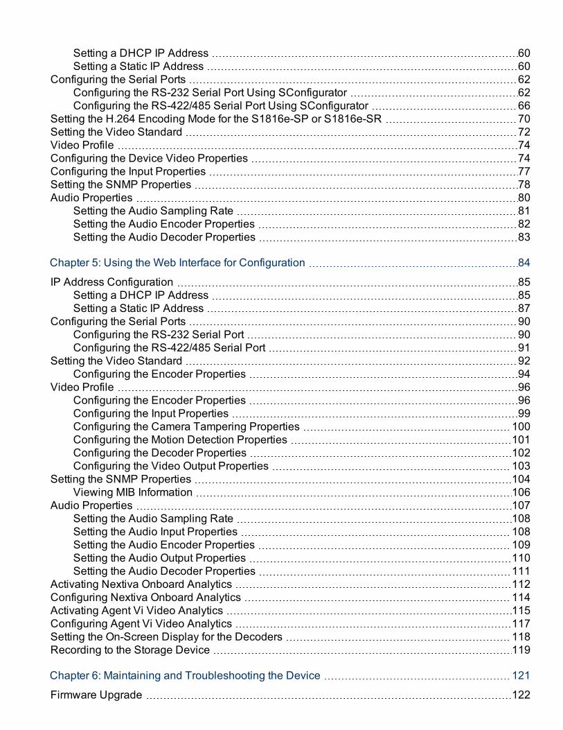
Setting a DHCP IP Address 60Setting a Static IP Address 60
Configuring the Serial Ports 62Configuring the RS-232 Serial Port Using SConfigurator 62Configuring the RS-422/485 Serial Port Using SConfigurator 66
Setting the H.264 Encoding Mode for the S1816e-SP or S1816e-SR 70Setting the Video Standard 72Video Profile 74Configuring the Device Video Properties 74Configuring the Input Properties 77Setting the SNMP Properties 78Audio Properties 80
Setting the Audio Sampling Rate 81Setting the Audio Encoder Properties 82Setting the Audio Decoder Properties 83
Chapter 5: Using the Web Interface for Configuration 84
IP Address Configuration 85Setting a DHCP IP Address 85Setting a Static IP Address 87
Configuring the Serial Ports 90Configuring the RS-232 Serial Port 90Configuring the RS-422/485 Serial Port 91
Setting the Video Standard 92Configuring the Encoder Properties 94
Video Profile 96Configuring the Encoder Properties 96Configuring the Input Properties 99Configuring the Camera Tampering Properties 100Configuring the Motion Detection Properties 101Configuring the Decoder Properties 102Configuring the Video Output Properties 103
Setting the SNMP Properties 104Viewing MIB Information 106
Audio Properties 107Setting the Audio Sampling Rate 108Setting the Audio Input Properties 108Setting the Audio Encoder Properties 109Setting the Audio Output Properties 110Setting the Audio Decoder Properties 111
Activating Nextiva Onboard Analytics 112Configuring Nextiva Onboard Analytics 114Activating Agent Vi Video Analytics 115Configuring Agent Vi Video Analytics 117Setting the On-Screen Display for the Decoders 118Recording to the Storage Device 119
Chapter 6: Maintaining and Troubleshooting the Device 121
Firmware Upgrade 122
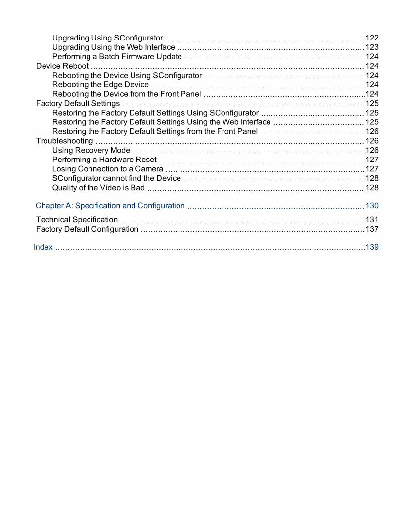
Upgrading Using SConfigurator 122Upgrading Using the Web Interface 123Performing a Batch Firmware Update 124
Device Reboot 124Rebooting the Device Using SConfigurator 124Rebooting the Edge Device 124Rebooting the Device from the Front Panel 124
Factory Default Settings 125Restoring the Factory Default Settings Using SConfigurator 125Restoring the Factory Default Settings Using the Web Interface 125Restoring the Factory Default Settings from the Front Panel 126
Troubleshooting 126Using Recovery Mode 126Performing a Hardware Reset 127Losing Connection to a Camera 127SConfigurator cannot find the Device 128Quality of the Video is Bad 128
Chapter A: Specification and Configuration 130
Technical Specification 131Factory Default Configuration 137
Index 139

PrefaceThe Nextiva® S1800e User Guide presents information and procedures oninstalling, configuring, and using the Nextiva encoders and decoders.
The Web Interface User Guide presents the information and procedures forconfiguring the Nextiva® S1800e series encoders and decoders.
© 2013 Verint Video Systems Inc. 8
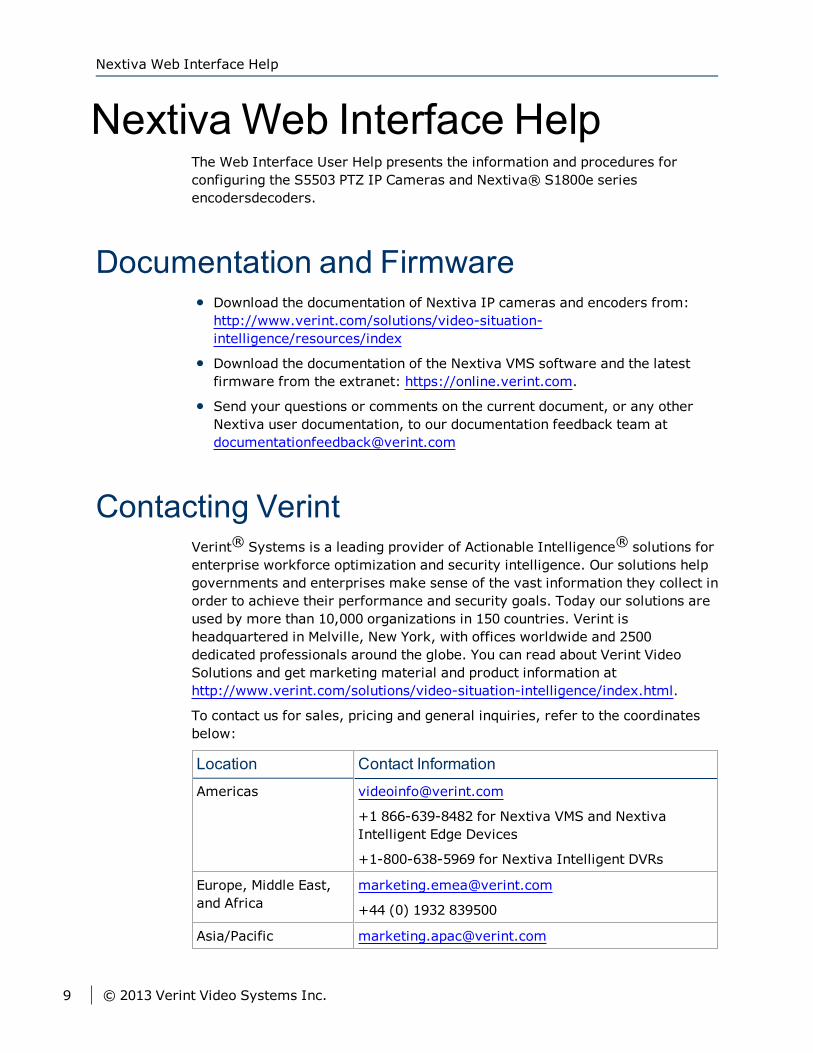
Nextiva Web Interface HelpThe Web Interface User Help presents the information and procedures forconfiguring the S5503 PTZ IP Cameras and Nextiva® S1800e seriesencodersdecoders.
Documentation and FirmwareDownload the documentation of Nextiva IP cameras and encoders from:http://www.verint.com/solutions/video-situation-intelligence/resources/index
Download the documentation of the Nextiva VMS software and the latestfirmware from the extranet: https://online.verint.com.
Send your questions or comments on the current document, or any otherNextiva user documentation, to our documentation feedback team [email protected]
Contacting VerintVerint® Systems is a leading provider of Actionable Intelligence® solutions forenterprise workforce optimization and security intelligence. Our solutions helpgovernments and enterprises make sense of the vast information they collect inorder to achieve their performance and security goals. Today our solutions areused by more than 10,000 organizations in 150 countries. Verint isheadquartered in Melville, New York, with offices worldwide and 2500dedicated professionals around the globe. You can read about Verint VideoSolutions and get marketing material and product information athttp://www.verint.com/solutions/video-situation-intelligence/index.html.
To contact us for sales, pricing and general inquiries, refer to the coordinatesbelow:
Location Contact Information
Americas [email protected]
+1 866-639-8482 for Nextiva VMS and NextivaIntelligent Edge Devices
+1-800-638-5969 for Nextiva Intelligent DVRs
Europe, Middle East,and Africa
+44 (0) 1932 839500
Asia/Pacific [email protected]
Nextiva Web Interface Help
9 © 2013 Verint Video Systems Inc.
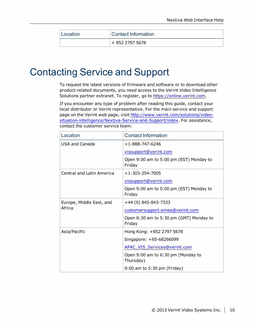
Location Contact Information
+ 852 2797 5678
Contacting Service and SupportTo request the latest versions of firmware and software or to download otherproduct-related documents, you need access to the Verint Video IntelligenceSolutions partner extranet. To register, go to https://online.verint.com.
If you encounter any type of problem after reading this guide, contact yourlocal distributor or Verint representative. For the main service and supportpage on the Verint web page, visit http://www.verint.com/solutions/video-situation-intelligence/Nextiva-Service-and-Support/index. For assistance,contact the customer service team:
Location Contact Information
USA and Canada +1-888-747-6246
Open 9:00 am to 5:00 pm (EST) Monday toFriday
Central and Latin America +1-303-254-7005
Open 9:00 am to 5:00 pm (EST) Monday toFriday
Europe, Middle East, andAfrica
+44 (0) 845-843-7333
Open 8:30 am to 5:30 pm (GMT) Monday toFriday
Asia/Pacific Hong Kong: +852 2797 5678
Singapore: +65-68266099
Open 9:00 am to 6:30 pm (Monday toThursday)
9:00 am to 5:30 pm (Friday)
Nextiva Web Interface Help
© 2013 Verint Video Systems Inc. 10
SafetyAlways observe the following precautions to reduce the risk of injury andequipment damage:
The S1800e series devices are for indoor use only.
Do not connect the S1800e series devices to any cabling (BNC,HDMI, PoE orotherwise) that runs outdoor.
The S1800e series devices should be placed on a secure flat surface ormounted using optional hardware.
The S1800e series devices should only be operated in a clean, dryenvironment.
For the multiport encoders, the operating temperature is 32ºF to 131ºF (0ºCto 55ºC), with maximum humidity at 95% non-condensing.
For single and dual port devices except the S1801e-POE, the the operatingtemperature is 32ºF to 140ºF (0ºC to 60ºC), with maximum humidity at95% non-condensing.
For the single port S1801e-POE, the operating temperature is 32ºF to 131ºF(0ºC to 55ºC), with maximum humidity at 95% non-condensing.
Only use the recommend power cable for powering the S1800e seriesdevices.
Do not install the S1800e series devices in an enclosed cabinet or othersmall area without ventilation.
Safety
11 © 2013 Verint Video Systems Inc.

Summary of ChangesThis section lists technical updates and new material added to the NextivaV3300 User Guide.
Revision 11 - May 2013This is the eleventh edition of the Nextiva S1800e Series User Guide.
What's NewUpdate to the Nextiva Onboard Analytics to allow users to enable/disablesurveillance analytics based on external data such as access controlsoftware.
RTSP basic authentication can now use the same credentials as the webpage.
Support for Polish.
Revision 10 - October 2012This is the tenth edition of the Nextiva S1800e Series User Guide.
What's NewNew low cost S1816e-SR multiport encoder.
Revision 9- June 2012This is the ninth edition of the Nextiva S1800e Series User Guide.
UpdatesDevice Overview now show the rear of both the S1808e and the S18016e.
© 2013 Verint Video Systems Inc. 12
Revision 8 - March 2012This is the eight edition of the Nextiva S1800e Series User Guide.
New FeatureSupport for AgentVi Video Analytics on the multiport encoders.
Revision 7 - August 2011This is the seventh edition of the Nextiva S1800e Series User Guide.
What's NewWeb Server port text box to allow you to configure the http port number touse.
DHCP Timeout text box allows you to set the timeout value.
Revision 6 - August 2011This is the sixth edition of the Nextiva S1800e Series User Guide.
Revision 5 - June 2011This is the fifth edition of the Nextiva S1800e Series User Guide.
What's NewControl of Pelco-D Type PTZ dome cameras connected to a Nextiva S1800eencoder is now supported through the Web Interface.
New SNMP Trap for camera tampering.
Support for Real Time Streaming Protocol (RTSP).
S1808e, S1816e, S1808e-A S1816e-A and S1816e-SP:
Supports resolutions up to D1.
Revision 8 - March 2012
13 © 2013 Verint Video Systems Inc.
S1801e, S1801e-R or S1801e-R-HD, S1802e, S1808e-A, S1816e-A:
Support for μ-LAW audio codec.
S1801e-R or S1801e-R-HDMI:
Support for decoding video from Nextiva S5000 IP Cameras
S1801e-R-HDMI: New 3 × 2 layout
UpdatesNextiva Onboard Analytics licensing page has been updated.
Revision 4 - December 2010This is the fourth edition of the Nextiva S1800e Series User Guide.
UpdatesThe U.S. Environmental Protection Agency (EPA) announced that as a resultof major success in moving the external power adapter market towardsgreater and more sustainable energy efficiency, effective December 31,2010, the EPA is cancelling the Energy Star program for external powersupplies (EPS). To conform to the EPA requirements, Verint is now statingthe efficiency level for all EPS.
Revision 3 - September 2010This is the third edition of the Nextiva S1800e Series User Guide.
Revision 2 - February 2010This is the second edition of the Nextiva S1800e Series User Guide.
What's NewS1816e-SP 16-video input encoder, a cost effective version withperformance of up to 4CIF/15fps
TCP/IP communication protocol support
Live Video through the Web Interface
Summary of Changes
© 2013 Verint Video Systems Inc. 14
Revision 1- October 2009This is the first edition of the Nextiva S1800e Series User Guide.
What's New8 or 16-video input encoders with up to triple streaming
H.264 and MPEG-4 video up to 4CIF/30fps providing maximum video qualityfor minimum data transfer and storage
Compact design accommodating up to 16 video streams in a 1U, 6-inch (15-cm) deep enclosure
Seamless integration with IT infrastructure including SNMP support and DualLAN interface
Sustainable, environmentally friendly solution with very low powerconsumption
Seamless integration with Nextiva Video Management Software for easyconfiguration and management
Intuitive Web Interface for configuring and troubleshooting the encoder
8 or 16 dry contacts inputs and 2 or 4 relay outputs for alarm configuration
On-board motion detection
Default serial port settings compatible with the most popular camera dataport configuration
RS-232 (max. 230Kbps) pluggable screw-terminal strip for integration withaccess control systems
RS-422/485 2/4 wires (max. 230Kbps) pluggable screw-terminal strip formotorized domes and camera
Revision 1- October 2009
15 © 2013 Verint Video Systems Inc.
The Nextiva® encoders are enterprise-class, H.264 enabled video encodersdesigned for large-scale, geographically distributed operations. These powerfulvideo devices offer a comprehensive feature set that includes full frame ratewith high resolution video on all ports.
The Nextiva® decoders incorporate advanced H.264 decompression technologyto deliver superior video quality and excellent performance in enterprise,critical infrastructure, and other video surveillance applications. Designed foruse with all Nextiva S1800e series single- and multi-port encoders and S5000IP cameras, the decoders are ideal for integration in distributed networks,including point-to-point applications. These compact decoders supports fourH.264 video streams, displaying up to six tiles on traditional CCTV monitors andhigh-definition LCD or plasma monitors
The following topics are discussed:
Hardware Overview 17
Security 24
Frame Rate and Performance for the Single- and Dual-Port Devices 24
Multiport Supported Resolutions 26
Multiport Supported Frame Rates 27
Supported Audio Formats 28
Understanding the LED Indicators 28
RTSP Support 30
Configuring the Input/Output Terminals 31
Chapter 1Chapter 1: S1800e Series Overview
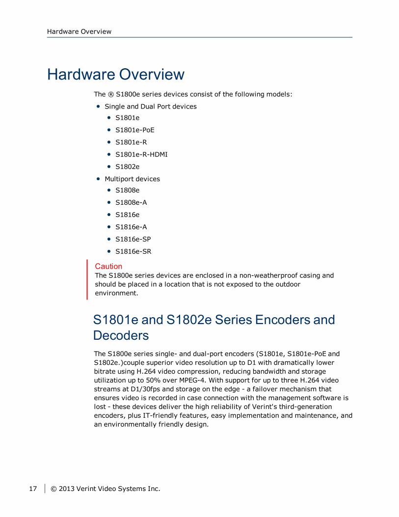
Hardware OverviewThe ® S1800e series devices consist of the following models:
Single and Dual Port devices
S1801e
S1801e-PoE
S1801e-R
S1801e-R-HDMI
S1802e
Multiport devices
S1808e
S1808e-A
S1816e
S1816e-A
S1816e-SP
S1816e-SR
CautionThe S1800e series devices are enclosed in a non-weatherproof casing andshould be placed in a location that is not exposed to the outdoorenvironment.
S1801e and S1802e Series Encoders andDecodersThe S1800e series single- and dual-port encoders (S1801e, S1801e-PoE andS1802e.)couple superior video resolution up to D1 with dramatically lowerbitrate using H.264 video compression, reducing bandwidth and storageutilization up to 50% over MPEG-4. With support for up to three H.264 videostreams at D1/30fps and storage on the edge - a failover mechanism thatensures video is recorded in case connection with the management software islost - these devices deliver the high reliability of Verint's third-generationencoders, plus IT-friendly features, easy implementation and maintenance, andan environmentally friendly design.
Hardware Overview
17 © 2013 Verint Video Systems Inc.
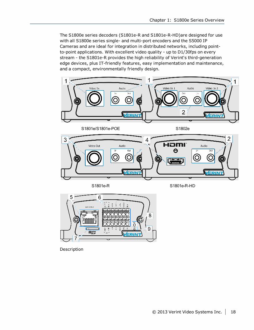
The S1800e series decoders (S1801e-R and S1801e-R-HD)are designed for usewith all S1800e series single- and multi-port encoders and the S5000 IPCameras and are ideal for integration in distributed networks, including point-to-point applications. With excellent video quality - up to D1/30fps on everystream - the S1801e-R provides the high reliability of Verint's third-generationedge devices, plus IT-friendly features, easy implementation and maintenance,and a compact, environmentally friendly design.
S1801e/S1801e-POE S1802e
S1801e-R S1801e-R-HD
Description
Chapter 1: S1800e Series Overview
© 2013 Verint Video Systems Inc. 18
1. Video input
2. Audio input and output
3. Video output
4. HDMI output
5. One RJ-45 network connector
6. Terminal Block
7. One MicroSD card slot (Only available on encoders)
8. Status LED
9. Reset button
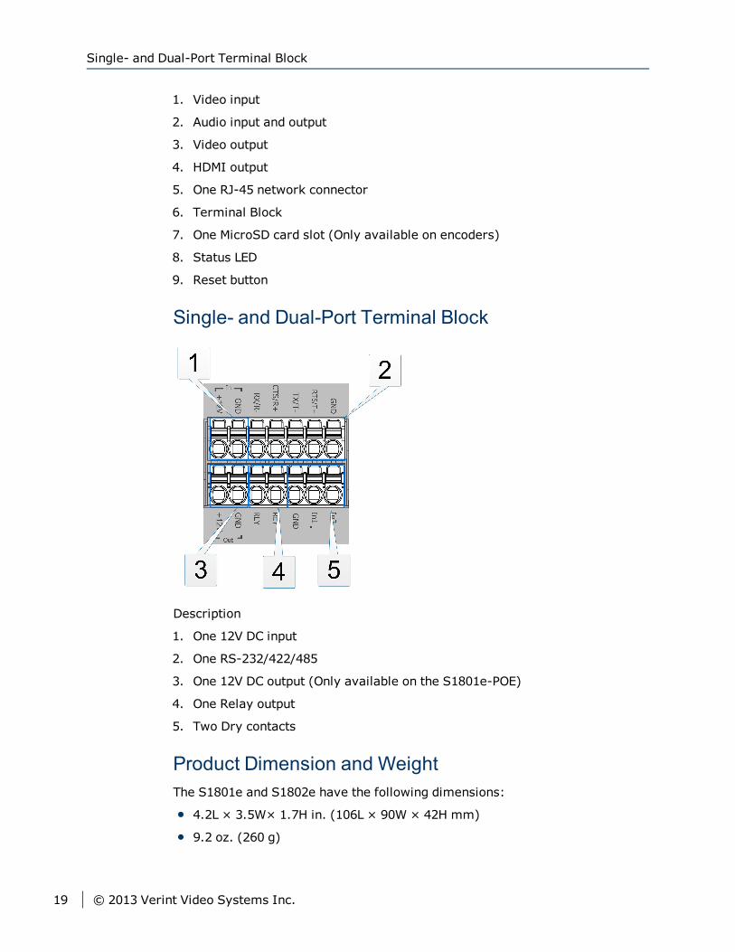
Single- and Dual-Port Terminal Block
Description
1. One 12V DC input
2. One RS-232/422/485
3. One 12V DC output (Only available on the S1801e-POE)
4. One Relay output
5. Two Dry contacts
Product Dimension and WeightThe S1801e and S1802e have the following dimensions:
4.2L × 3.5W× 1.7H in. (106L × 90W × 42H mm)
9.2 oz. (260 g)
Single- and Dual-Port Terminal Block
19 © 2013 Verint Video Systems Inc.
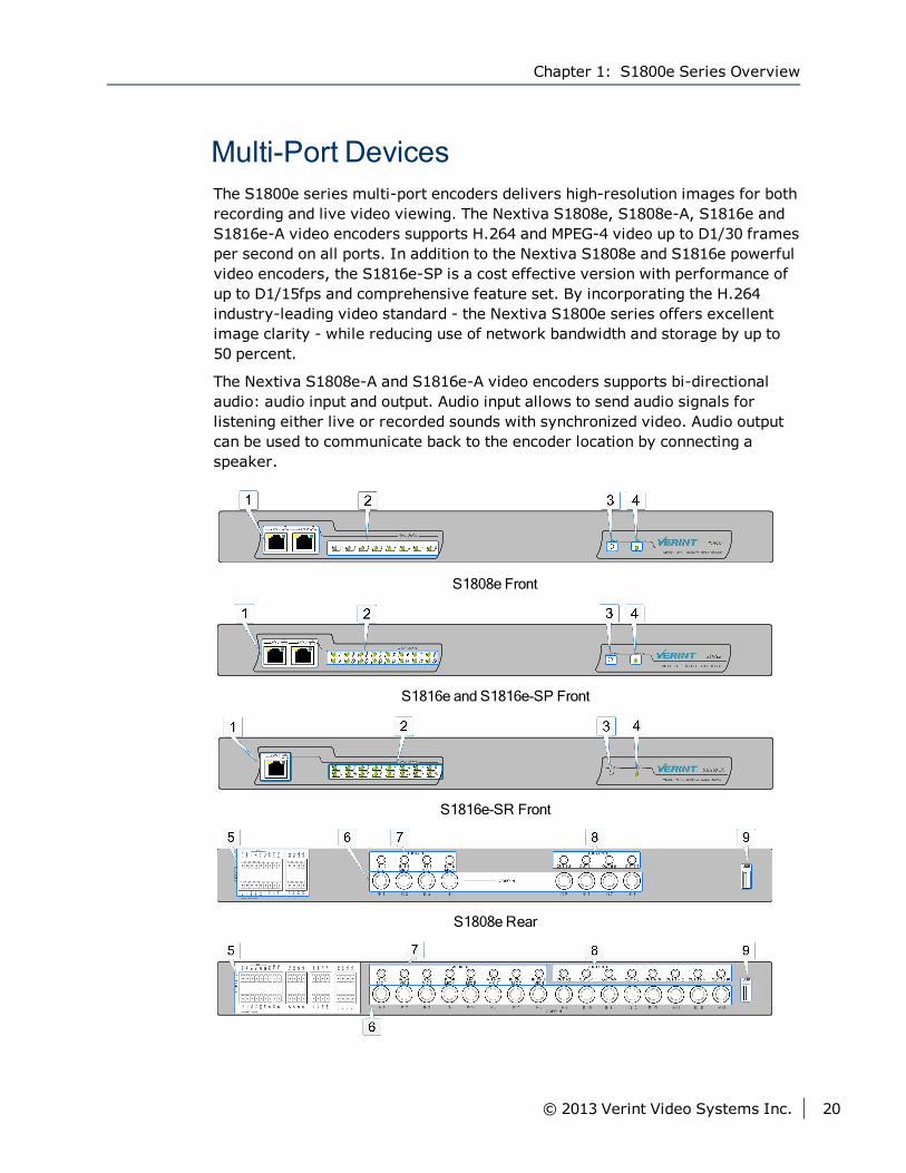
Multi-Port DevicesThe S1800e series multi-port encoders delivers high-resolution images for bothrecording and live video viewing. The Nextiva S1808e, S1808e-A, S1816e andS1816e-A video encoders supports H.264 and MPEG-4 video up to D1/30 framesper second on all ports. In addition to the Nextiva S1808e and S1816e powerfulvideo encoders, the S1816e-SP is a cost effective version with performance ofup to D1/15fps and comprehensive feature set. By incorporating the H.264industry-leading video standard - the Nextiva S1800e series offers excellentimage clarity - while reducing use of network bandwidth and storage by up to50 percent.
The Nextiva S1808e-A and S1816e-A video encoders supports bi-directionalaudio: audio input and output. Audio input allows to send audio signals forlistening either live or recorded sounds with synchronized video. Audio outputcan be used to communicate back to the encoder location by connecting aspeaker.
S1808e Front
S1816e and S1816e-SP Front
S1816e-SR Front
S1808e Rear
Chapter 1: S1800e Series Overview
© 2013 Verint Video Systems Inc. 20
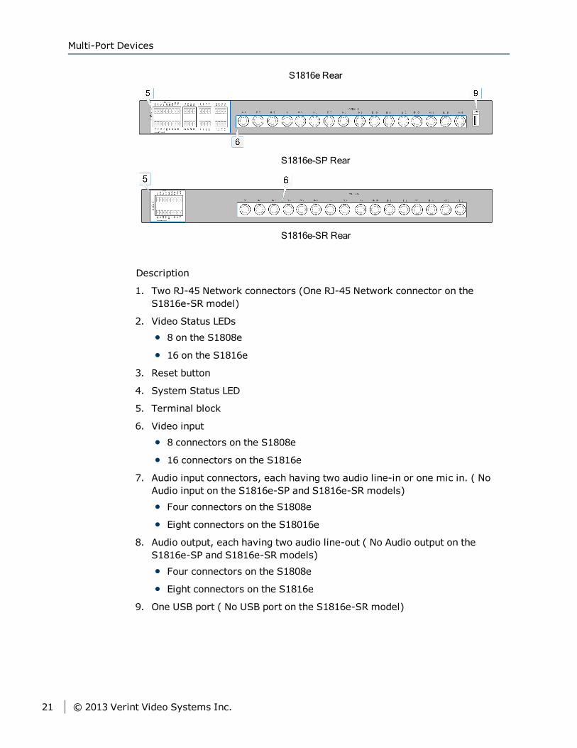
S1816e Rear
S1816e-SP Rear
S1816e-SR Rear
Description
1. Two RJ-45 Network connectors (One RJ-45 Network connector on theS1816e-SR model)
2. Video Status LEDs
8 on the S1808e
16 on the S1816e
3. Reset button
4. System Status LED
5. Terminal block
6. Video input
8 connectors on the S1808e
16 connectors on the S1816e
7. Audio input connectors, each having two audio line-in or one mic in. ( NoAudio input on the S1816e-SP and S1816e-SR models)
Four connectors on the S1808e
Eight connectors on the S18016e
8. Audio output, each having two audio line-out ( No Audio output on theS1816e-SP and S1816e-SR models)
Four connectors on the S1808e
Eight connectors on the S1816e
9. One USB port ( No USB port on the S1816e-SR model)
Multi-Port Devices
21 © 2013 Verint Video Systems Inc.
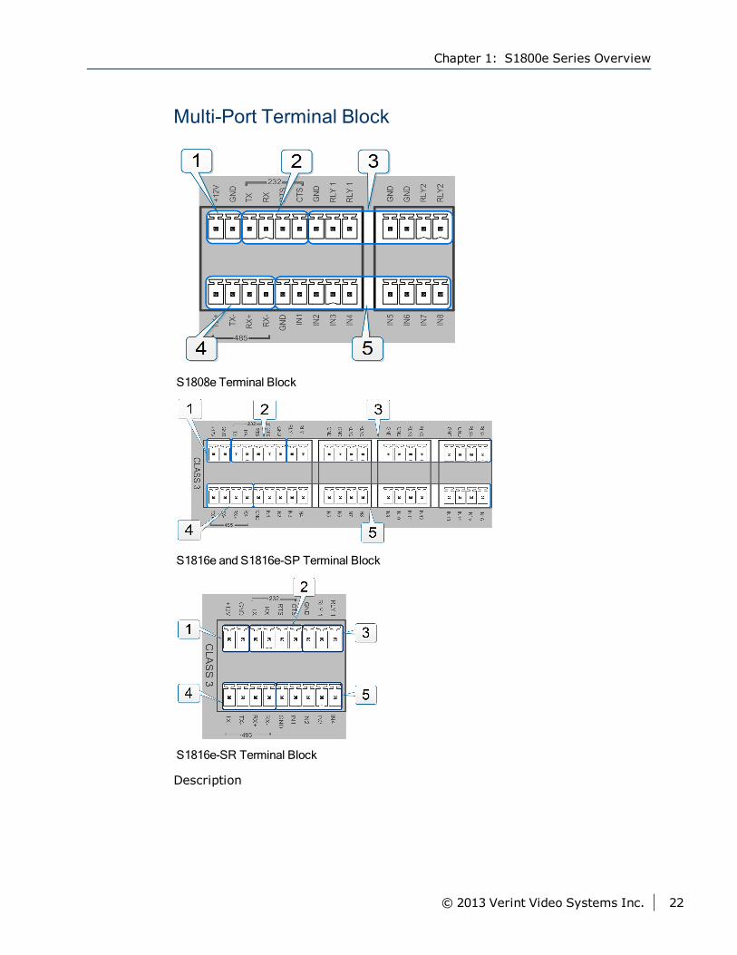
Multi-Port Terminal Block
S1808e Terminal Block
S1816e and S1816e-SP Terminal Block
S1816e-SR Terminal Block
Description
Chapter 1: S1800e Series Overview
© 2013 Verint Video Systems Inc. 22
1. One 12V DC input
2. One RS-232
3. Relay output
Two on the S1808e
Four on the S1816e
One on the S1816e-SR
4. RS 422/485
5. Dry contacts
8 on the S1808e
16 on the S1816e
4 on the S1816e-SR
Product Dimension and WeightThe S1808e, S1808e-A, S1816e, S1816e-A, S1816e-SP and S1816e-SR have thefollowing dimensions:
17L × 6.6W ×1.7H in. (430L × 67.68W × 42.6H mm)
4.0 lb. (1.8 kg)
Nextiva Onboard AnalyticsNextiva Onboard Analytics is a licensed feature available on the S1808e,S1808e-A, S1816e and S1816e-A multiport encoders. Nextiva OnboardAnalytics supports up to four video inputs (1, 2, 5, and 6 on the S1808e) and (1,2, 9, and 10 on the S1816e).
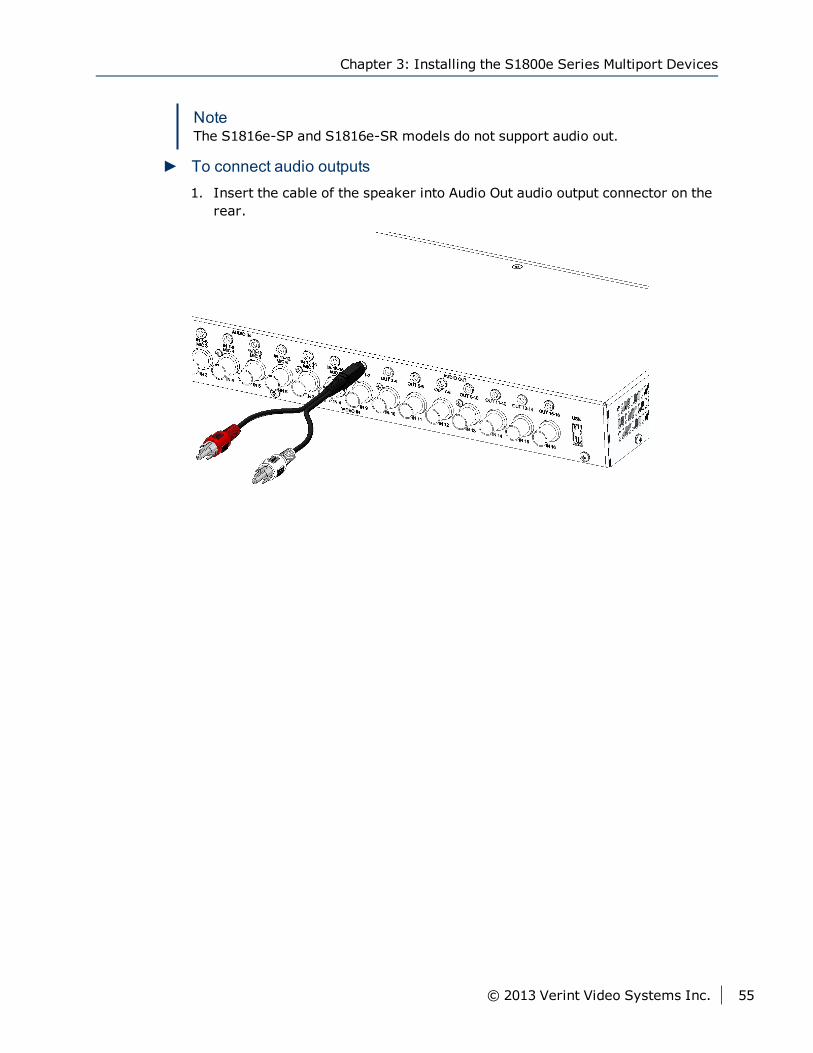
NoteThe S1816e-SP and S1816e-SR do not support Nextiva Onboard Analytics.
The Onboard Analytics Web Console is accessible through the Web Interfaceand the Analytics Web Console allows you to view video channels, create videoanalytics rules, configure your device for analytics, and change parametersthat control how events are detected.
Product Dimension and Weight
23 © 2013 Verint Video Systems Inc.

SecurityEvery S1800e series device comes with a unique SSL (Secure Sockets Layer)certificate for securing its IP link. SSL is a commonly used protocol formanaging the security of IP message transmission. With the SSL protocol, thefollowing data: Web Control Data, and VSIP communication are secured. Formore information on activating the SSL security, refer to the SConfiguratorUser Guide, Web Interface User Guide or your Nextiva Administration Guide.
Frame Rate and Performance for theSingle- and Dual-Port Devices
The S1801e and S1802e encoders support H.264 and MJPEG video up toD1/30fps on all streams simultaneously for up to 10Mbps.
The available video frame rates (frames per second) of each encoder are:
NTSC-1, 2, 3, 3.75, 5, 6, 7.5, 10, 15, or 30 fps
PAL-1, 2.5, 5, 6.75, 8.33, 12.5, or 25 fps
Encoders 1, 2 and 3 are H.264 and Encoder 4 is MJPEG.
A typical scenario would be using encoder 1 as the recorder, since it is theprimary H.264 encoder. Encoder 3 or 4 can be used for viewing or recording,depending if you want to view live video in H.264 or MJPEG.
Supported ResolutionThe following table lists the video resolutions supported by the S1801e andS1802e encoders.
Resolution NTSC PALCIF 352 × 240 352 × 288
2CIF 704 × 240 704 × 288
4CIF 704 × 480 704 × 576
D1 720 × 480 720 × 576
Chapter 1: S1800e Series Overview
© 2013 Verint Video Systems Inc. 24
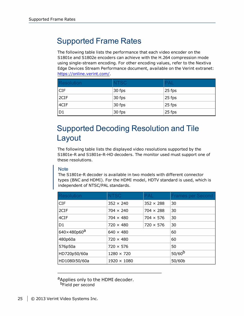
Supported Frame RatesThe following table lists the performance that each video encoder on theS1801e and S1802e encoders can achieve with the H.264 compression modeusing single-stream encoding. For other encoding values, refer to the NextivaEdge Devices Stream Performance document, available on the Verint extranet:https://online.verint.com/.
Resolution NTSC PALCIF 30 fps 25 fps
2CIF 30 fps 25 fps
4CIF 30 fps 25 fps
D1 30 fps 25 fps
Supported Decoding Resolution and TileLayoutThe following table lists the displayed video resolutions supported by theS1801e-R and S1801e-R-HD decoders. The monitor used must support one ofthese resolutions.
NoteThe S1801e-R decoder is available in two models with different connectortypes (BNC and HDMI). For the HDMI model, HDTV standard is used, which isindependent of NTSC/PAL standards.
Resolution NTSC PAL Frames per SecondCIF 352 × 240 352 × 288 30
2CIF 704 × 240 704 × 288 30
4CIF 704 × 480 704 × 576 30
D1 720 × 480 720 × 576 30
640×480p60a 640 × 480 60
480p60a 720 × 480 60
576p50a 720 × 576 50
HD720p50/60a 1280 × 720 50/60b
HD1080i50/60a 1920 × 1080 50/60b
aApplies only to the HDMI decoder.bField per second
Supported Frame Rates
25 © 2013 Verint Video Systems Inc.
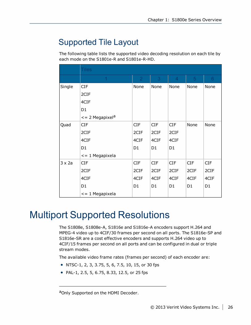
Supported Tile LayoutThe following table lists the supported video decoding resolution on each tile byeach mode on the S1801e-R and S1801e-R-HD.
Tiles
1 2 3 4 5 6Single CIF
2CIF
4CIF
D1
<= 2 Megapixela
None None None None None
Quad CIF
2CIF
4CIF
D1
<= 1 Megapixela
CIF
2CIF
4CIF
D1
CIF
2CIF
4CIF
D1
CIF
2CIF
4CIF
D1
None None
3 x 2a CIF
2CIF
4CIF
D1
<= 1 Megapixela
CIF
2CIF
4CIF
D1
CIF
2CIF
4CIF
D1
CIF
2CIF
4CIF
D1
CIF
2CIF
4CIF
D1
CIF
2CIF
4CIF
D1
Multiport Supported ResolutionsThe S1808e, S1808e-A, S1816e and S1816e-A encoders support H.264 andMPEG-4 video up to 4CIF/30 frames per second on all ports. The S1816e-SP andS1816e-SR are a cost effective encoders and supports H.264 video up to4CIF/15 frames per second on all ports and can be configured in dual or triplestream modes.
The available video frame rates (frames per second) of each encoder are:
NTSC-1, 2, 3, 3.75, 5, 6, 7.5, 10, 15, or 30 fps
PAL-1, 2.5, 5, 6.75, 8.33, 12.5, or 25 fps
aOnly Supported on the HDMI Decoder.
Chapter 1: S1800e Series Overview
© 2013 Verint Video Systems Inc. 26
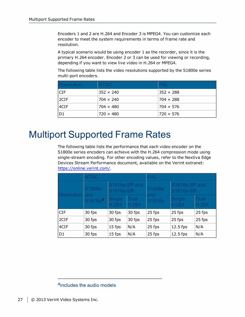
Encoders 1 and 2 are H.264 and Encoder 3 is MPEG4. You can customize eachencoder to meet the system requirements in terms of frame rate andresolution.
A typical scenario would be using encoder 1 as the recorder, since it is theprimary H.264 encoder. Encoder 2 or 3 can be used for viewing or recording,depending if you want to view live video in H.264 or MPEG4.
The following table lists the video resolutions supported by the S1800e seriesmulti-port encoders.
Resolution NTSC PALCIF 352 × 240 352 × 288
2CIF 704 × 240 704 × 288
4CIF 704 × 480 704 × 576
D1 720 × 480 720 × 576
Multiport Supported Frame RatesThe following table lists the performance that each video encoder on theS1800e series encoders can achieve with the H.264 compression mode usingsingle-stream encoding. For other encoding values, refer to the Nextiva EdgeDevices Stream Performance document, available on the Verint extranet:https://online.verint.com/.
NTSC PAL
ResolutionS1808eandS1816ea
S1816e-SP andS1816e-SR S1808e
andS1816e
S1816e-SP andS1816e-SR
SingleH.264
DualH.264
SingleH.264
DualH.264
CIF 30 fps 30 fps 30 fps 25 fps 25 fps 25 fps
2CIF 30 fps 30 fps 30 fps 25 fps 25 fps 25 fps
4CIF 30 fps 15 fps N/A 25 fps 12.5 fps N/A
D1 30 fps 15 fps N/A 25 fps 12.5 fps N/A
aincludes the audio models
Multiport Supported Frame Rates
27 © 2013 Verint Video Systems Inc.
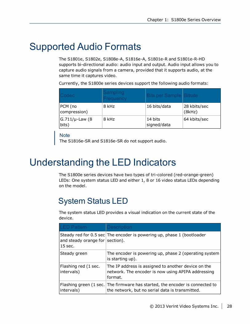
Supported Audio FormatsThe S1801e, S1802e, S1808e-A, S1816e-A, S1801e-R and S1801e-R-HDsupports bi-directional audio: audio input and output. Audio input allows you tocapture audio signals from a camera, provided that it supports audio, at thesame time it captures video.
Currently, the S1800e series devices support the following audio formats:
Codec SamplingFrequency Bits per Sample Bitrate
PCM (nocompression)
8 kHz 16 bits/data 28 kbits/sec(8kHz)
G.711/μ-Law (8bits)
8 kHz 14 bitssigned/data
64 kbits/sec
NoteThe S1816e-SR and S1816e-SR do not support audio.
Understanding the LED IndicatorsThe S1800e series devices have two types of tri-colored (red-orange-green)LEDs: One system status LED and either 1, 8 or 16 video status LEDs dependingon the model.
System Status LEDThe system status LED provides a visual indication on the current state of thedevice.
LED Pattern DescriptionSteady red for 0.5 secand steady orange for15 sec.
The encoder is powering up, phase 1 (bootloadersection).
Steady green The encoder is powering up, phase 2 (operating systemis starting up).
Flashing red (1 sec.intervals)
The IP address is assigned to another device on thenetwork. The encoder is now using APIPA addressingformat.
Flashing green (1 sec.intervals)
The firmware has started, the encoder is connected tothe network, but no serial data is transmitted.
Chapter 1: S1800e Series Overview
© 2013 Verint Video Systems Inc. 28
LED Pattern DescriptionFlashing green (0.2sec. intervals)
The firmware has started, the encoder is connected tothe network, and serial data is transmitted.
Flashing green (3 sec.intervals)
The firmware has started, but the encoder is notconnected to the network.
Flashing green-red (1sec. intervals)
The encoder is undergoing a firmware update.
Flashing red (0.1 sec.intervals)
The encoder is being identified.
Flashing orange (1sec intervals)
The encoder failed to boot normally and enteredrecovery mode. The firmware needs to be updatedthrough SConfigurator or the Web Interface. Theencoder is using the static IP address assigned by theuser.
Flashing orange (3blinks at 1 secintervals) and 2 quickred pulses (0.5 secinterval)
The encoder failed to boot normally and enteredrecovery mode. The firmware needs to be updatedthrough SConfigurator or the Web Interface. Theencoder is using the APIPA addressing format.
Flashing red-orange(1 sec intervals)
There is an internal error that is preventing theencoder from starting normally. Shut down theencoder, wait 30 seconds, then start it again. If thecondition persists, call Verint Video Solutions support.
LED not lit Check the power supply and cabling. If power isavailable and the LED stays off, call Verint VideoSolutions support.
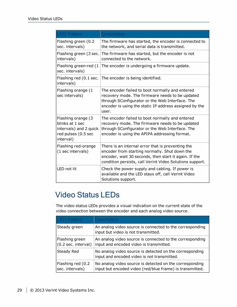
Video Status LEDsThe video status LEDs provides a visual indication on the current state of thevideo connection between the encoder and each analog video source.
LED Pattern DescriptionSteady green An analog video source is connected to the corresponding
input but video is not transmitted.
Flashing green(0.2 sec. interval)
An analog video source is connected to the correspondinginput and encoded video is transmitted.
Steady Red No analog video source is detected on the correspondinginput and encoded video is not transmitted.
Flashing red (0.2sec. intervals)
No analog video source is detected on the correspondinginput but encoded video (red/blue frame) is transmitted.
Video Status LEDs
29 © 2013 Verint Video Systems Inc.
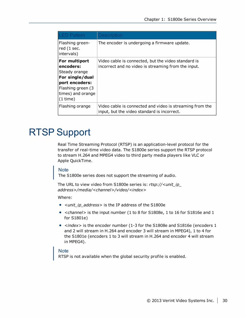
LED Pattern DescriptionFlashing green-red (1 sec.intervals)
The encoder is undergoing a firmware update.
For multiportencoders:Steady orangeFor single/dualport encoders:Flashing green (3times) and orange(1 time)
Video cable is connected, but the video standard isincorrect and no video is streaming from the input.
Flashing orange Video cable is connected and video is streaming from theinput, but the video standard is incorrect.
RTSP SupportReal Time Streaming Protocol (RTSP) is an application-level protocol for thetransfer of real-time video data. The S1800e series support the RTSP protocolto stream H.264 and MPEG4 video to third party media players like VLC orApple QuickTime.
NoteThe S1800e series does not support the streaming of audio.
The URL to view video from S1800e series is: rtsp://<unit_ip_address>/media/<channel>/video/<index>
Where:
<unit_ip_address> is the IP address of the S1800e
<channel> is the input number (1 to 8 for S1808e, 1 to 16 for S1816e and 1for S1801e)
<index> is the encoder number (1-3 for the S1808e and S1816e (encoders 1and 2 will stream in H.264 and encoder 3 will stream in MPEG4), 1 to 4 forthe S1801e (encoders 1 to 3 will stream in H.264 and encoder 4 will streamin MPEG4).
NoteRTSP is not available when the global security profile is enabled.
Chapter 1: S1800e Series Overview
© 2013 Verint Video Systems Inc. 30

Configuring the Input/Output TerminalsThe rear panel of the S1800e series devices has 1, 2, 8 or 16 dry contact inputsand 1, 2 or 4 relay output terminals for triggers and alarms depending on themodel. Using a video management software such as Nextiva VideoManagement Software, you can create scenarios with Nextiva VMS EventManager to generate a response through the relay outputs to pre-definedsystem and motion events detected in Nextiva from sensors connected to thedry contact inputs. For complete information on using the Nextiva VMS EventManager, refer to the current Nextiva VMS Administration Guide.
Configuring the Input/Output Terminals
31 © 2013 Verint Video Systems Inc.

This chapter describes the installation and configuration steps you need toperform to prepare the S1800e series devices for operation.
CautionThe S1800e series devices are enclosed in a non-weatherproof steel casingand should be placed in an indoor environment.
The following topics are discussed:
Package Contents 33
Installing on a Flat Surface 33
Installing in a Rack 33
Powering the Devices 35
Powering the S1801e-POE 37
Connecting Analog Cameras 37
Connecting Network Cables 38
Connecting a Serial Device 39
Connecting Audio Inputs 43
Connecting Audio Output 43
Chapter 2Chapter 2: Installing the Single-and
Dual-Port Devices
Package ContentsEach installation kit contains the following:
One S1801e, S1801e-PoE, S1802e, S1801e-R or S1801e-R-HD device
One set of rack-mount brackets with four screws (Philips M3 x 6mm panhead)
One Nextiva S1800e series Quick Installation Guide
PS12: Efficiency level V compliant power supply
Optional AccessoriesYou can order the following power supplies when purchasing the encoder ordecoder:
VRM8: 19-inch rack mount panel for eight units (single- or dual-portsdevices)
PSPOE: 802.3af compliant Power over Ethernet injector
Installing on a Flat SurfaceThis section explains how to install the S1800e on a desktop or flat surface.
► To install on a flat surface1. Remove any debris and dust from the surface as well as the surrounding
area.
2. Place the device on the flat surface.
3. Ensure that you have access to both the front and rear of the device and thatthe fan airflow is not blocked.
Installing in a RackThis section explains how to install the device in a rack.
Package Contents
33 © 2013 Verint Video Systems Inc.
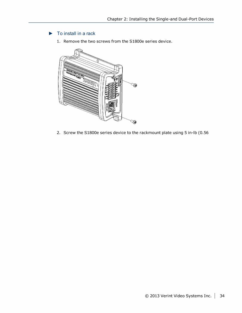
► To install in a rack1. Remove the two screws from the S1800e series device.
2. Screw the S1800e series device to the rackmount plate using 5 in-lb (0.56
Chapter 2: Installing the Single-and Dual-Port Devices
© 2013 Verint Video Systems Inc. 34
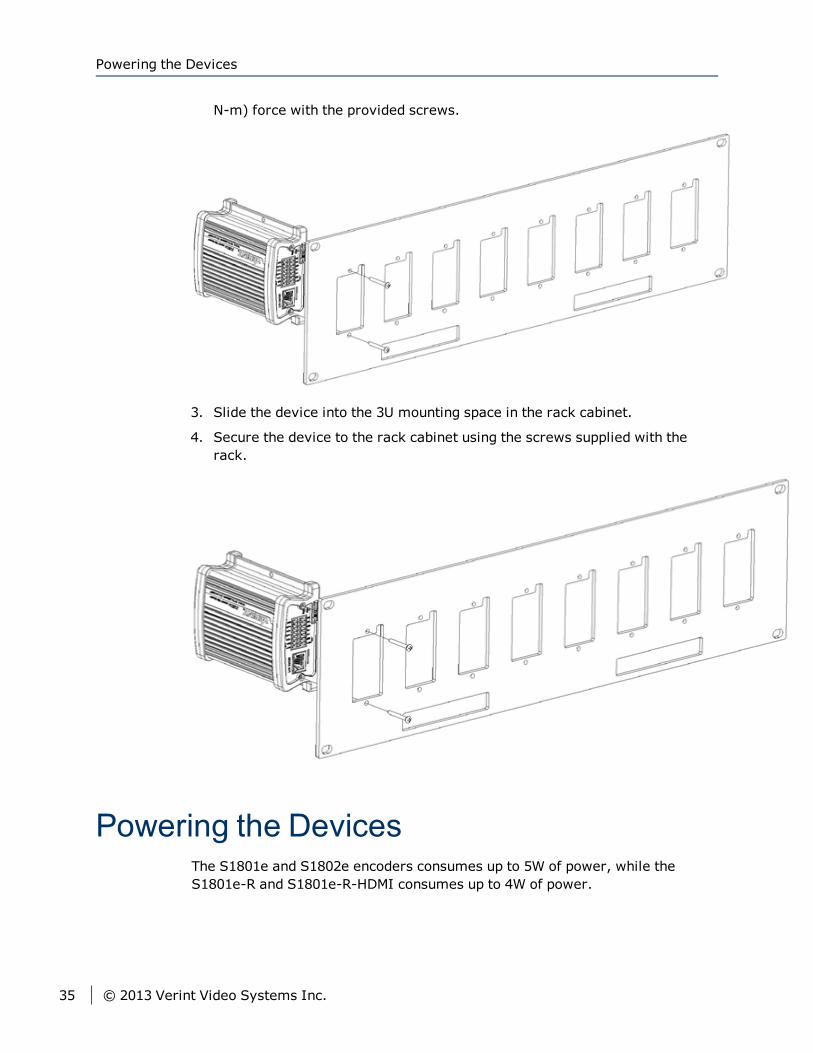
N-m) force with the provided screws.
3. Slide the device into the 3U mounting space in the rack cabinet.
4. Secure the device to the rack cabinet using the screws supplied with therack.
Powering the DevicesThe S1801e and S1802e encoders consumes up to 5W of power, while theS1801e-R and S1801e-R-HDMI consumes up to 4W of power.
Powering the Devices
35 © 2013 Verint Video Systems Inc.
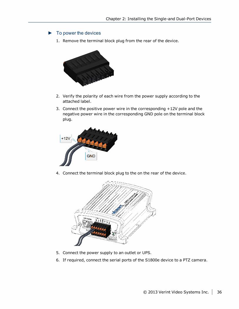
► To power the devices1. Remove the terminal block plug from the rear of the device.
2. Verify the polarity of each wire from the power supply according to theattached label.
3. Connect the positive power wire in the corresponding +12V pole and thenegative power wire in the corresponding GND pole on the terminal blockplug.
4. Connect the terminal block plug to the on the rear of the device.
5. Connect the power supply to an outlet or UPS.
6. If required, connect the serial ports of the S1800e device to a PTZ camera.
Chapter 2: Installing the Single-and Dual-Port Devices
© 2013 Verint Video Systems Inc. 36
Powering the S1801e-POEThe S1801e and S1802e encoders consumes up to 5W of power, while theS1801e-R and S1801e-R-HDMI consumes up to 4W of power.
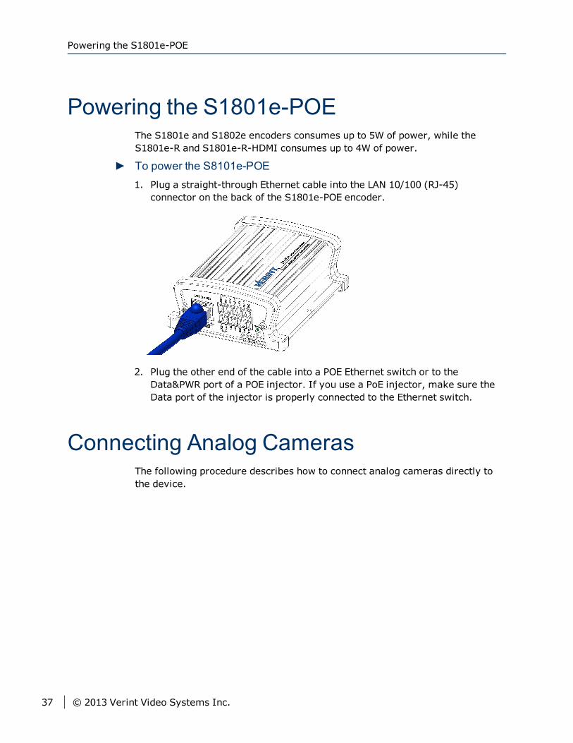
► To power the S8101e-POE1. Plug a straight-through Ethernet cable into the LAN 10/100 (RJ-45)
connector on the back of the S1801e-POE encoder.
2. Plug the other end of the cable into a POE Ethernet switch or to theData&PWR port of a POE injector. If you use a PoE injector, make sure theData port of the injector is properly connected to the Ethernet switch.
Connecting Analog CamerasThe following procedure describes how to connect analog cameras directly tothe device.
Powering the S1801e-POE
37 © 2013 Verint Video Systems Inc.
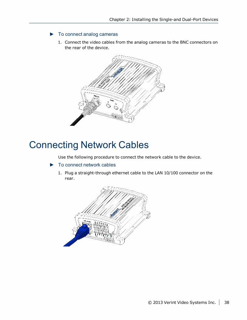
► To connect analog cameras1. Connect the video cables from the analog cameras to the BNC connectors on
the rear of the device.
Connecting Network CablesUse the following procedure to connect the network cable to the device.
► To connect network cables1. Plug a straight-through ethernet cable to the LAN 10/100 connector on the
rear.
Chapter 2: Installing the Single-and Dual-Port Devices
© 2013 Verint Video Systems Inc. 38
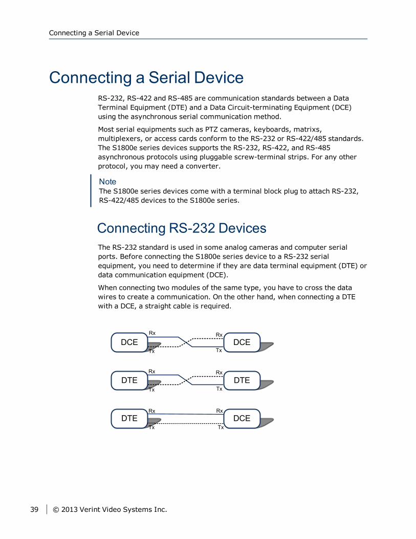
Connecting a Serial DeviceRS-232, RS-422 and RS-485 are communication standards between a DataTerminal Equipment (DTE) and a Data Circuit-terminating Equipment (DCE)using the asynchronous serial communication method.
Most serial equipments such as PTZ cameras, keyboards, matrixs,multiplexers, or access cards conform to the RS-232 or RS-422/485 standards.The S1800e series devices supports the RS-232, RS-422, and RS-485asynchronous protocols using pluggable screw-terminal strips. For any otherprotocol, you may need a converter.
NoteThe S1800e series devices come with a terminal block plug to attach RS-232,RS-422/485 devices to the S1800e series.
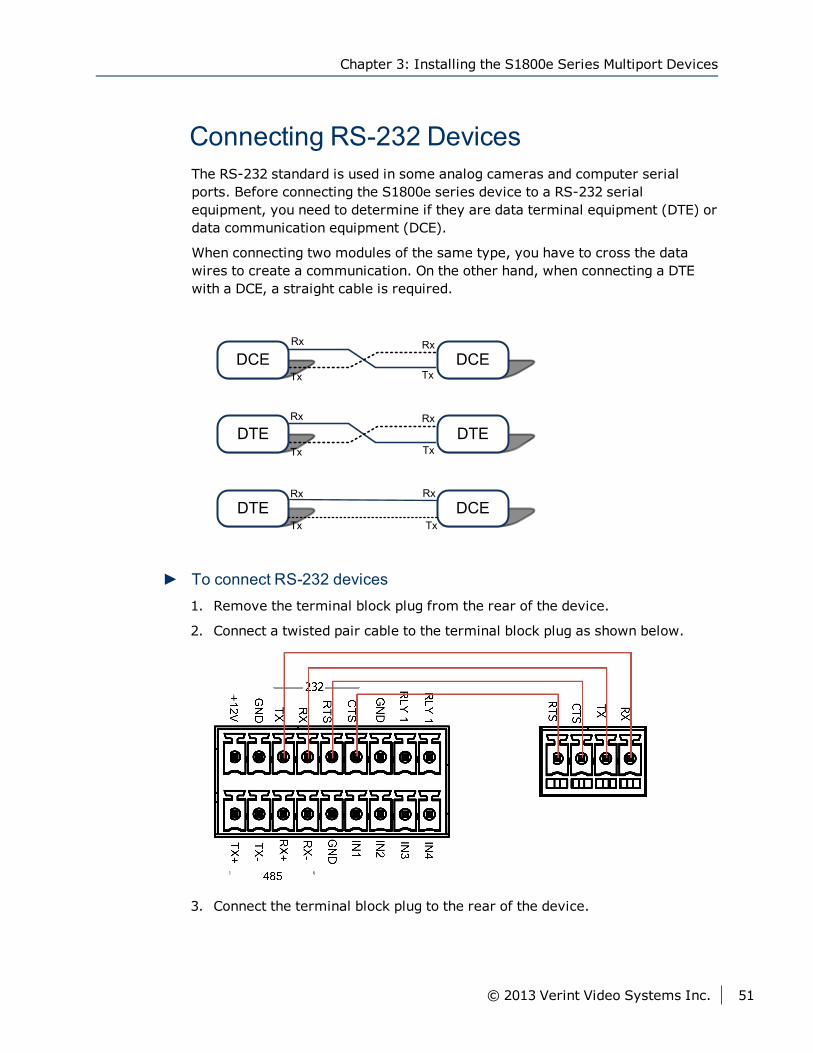
Connecting RS-232 DevicesThe RS-232 standard is used in some analog cameras and computer serialports. Before connecting the S1800e series device to a RS-232 serialequipment, you need to determine if they are data terminal equipment (DTE) ordata communication equipment (DCE).
When connecting two modules of the same type, you have to cross the datawires to create a communication. On the other hand, when connecting a DTEwith a DCE, a straight cable is required.
Connecting a Serial Device
39 © 2013 Verint Video Systems Inc.
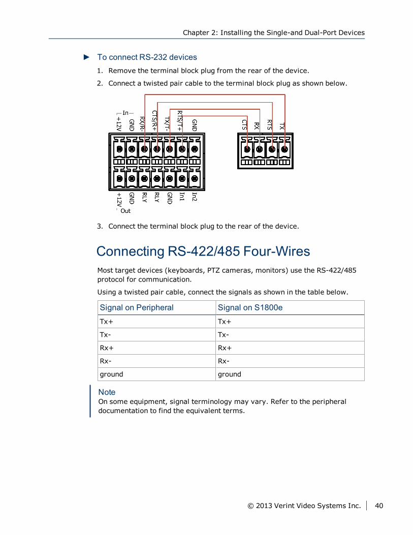
► To connect RS-232 devices1. Remove the terminal block plug from the rear of the device.
2. Connect a twisted pair cable to the terminal block plug as shown below.
3. Connect the terminal block plug to the rear of the device.
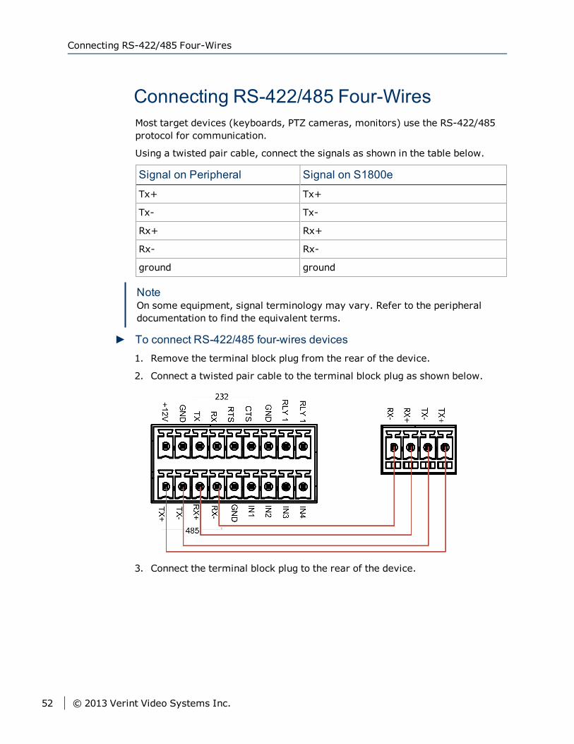
Connecting RS-422/485 Four-WiresMost target devices (keyboards, PTZ cameras, monitors) use the RS-422/485protocol for communication.
Using a twisted pair cable, connect the signals as shown in the table below.
Signal on Peripheral Signal on S1800e
Tx+ Tx+
Tx- Tx-
Rx+ Rx+
Rx- Rx-
ground ground
NoteOn some equipment, signal terminology may vary. Refer to the peripheraldocumentation to find the equivalent terms.
Chapter 2: Installing the Single-and Dual-Port Devices
© 2013 Verint Video Systems Inc. 40
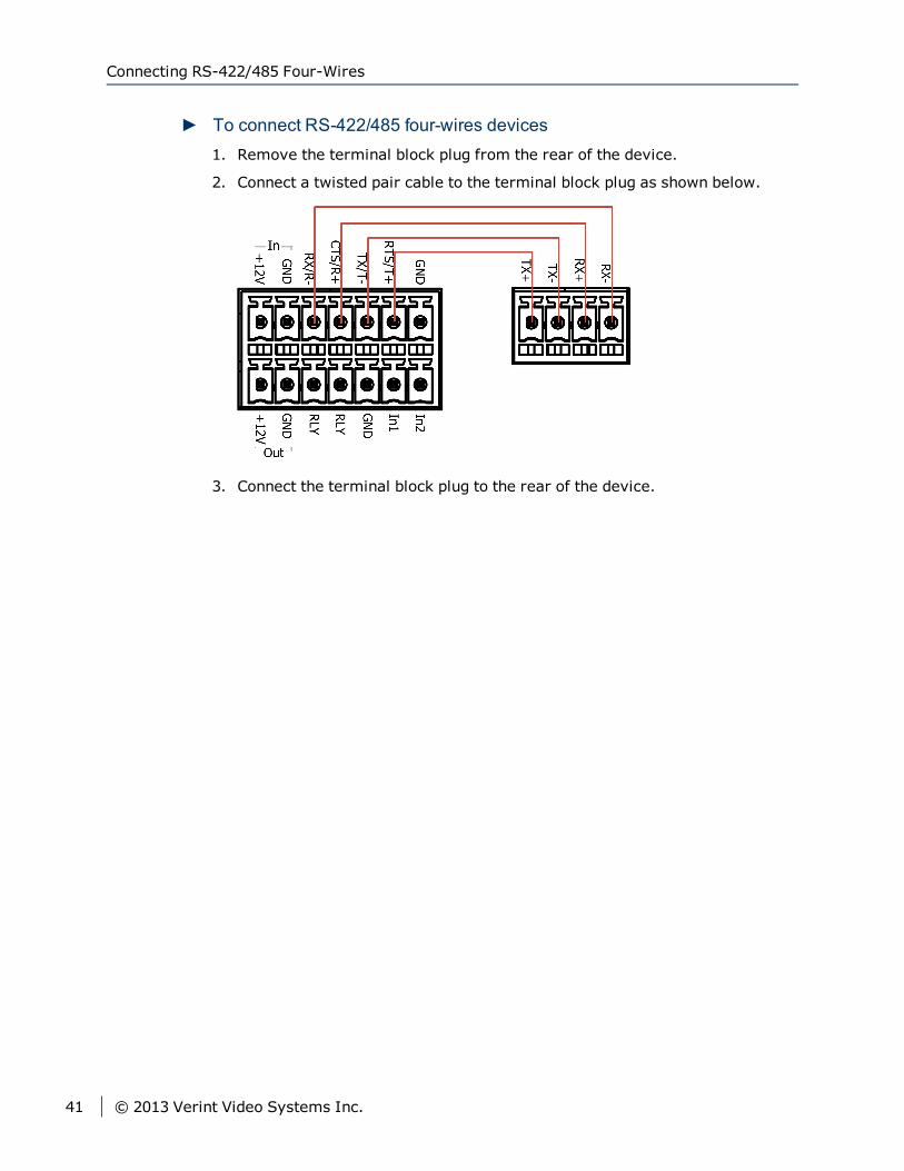
► To connect RS-422/485 four-wires devices1. Remove the terminal block plug from the rear of the device.
2. Connect a twisted pair cable to the terminal block plug as shown below.
3. Connect the terminal block plug to the rear of the device.
Connecting RS-422/485 Four-Wires
41 © 2013 Verint Video Systems Inc.
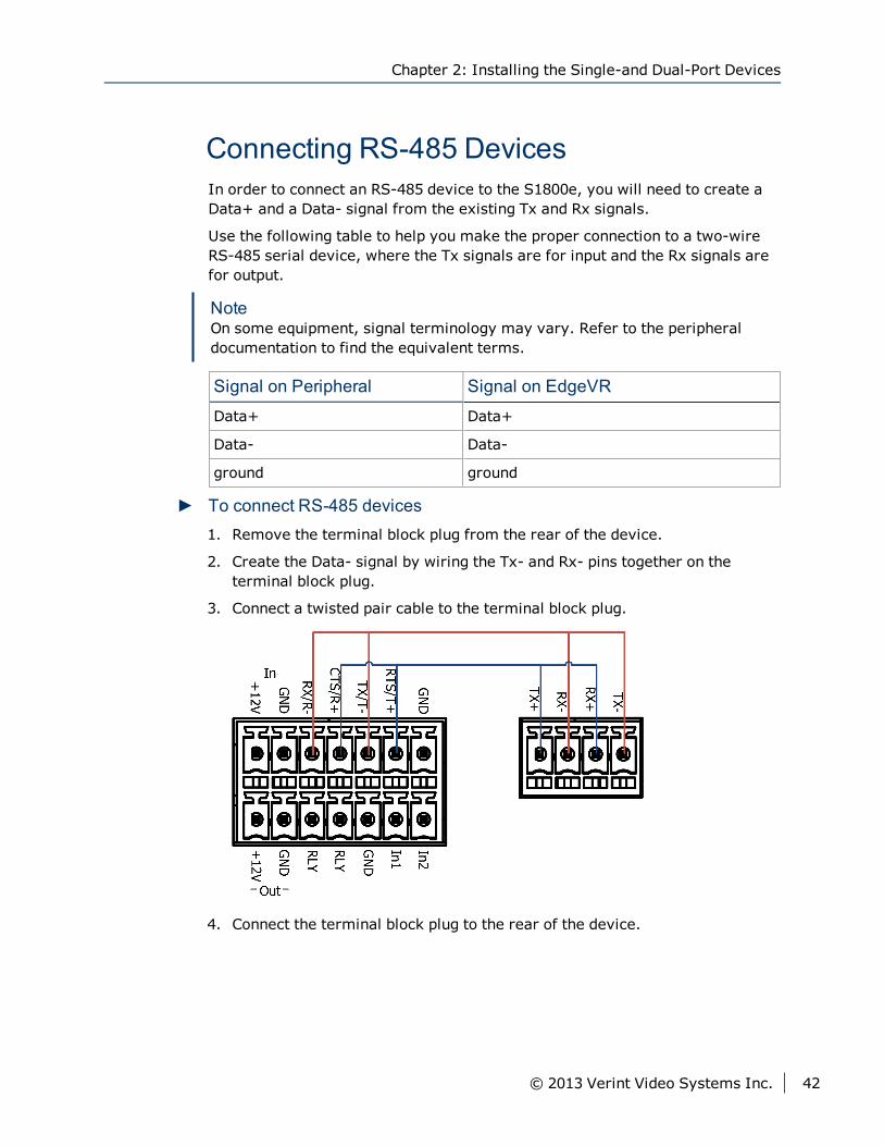
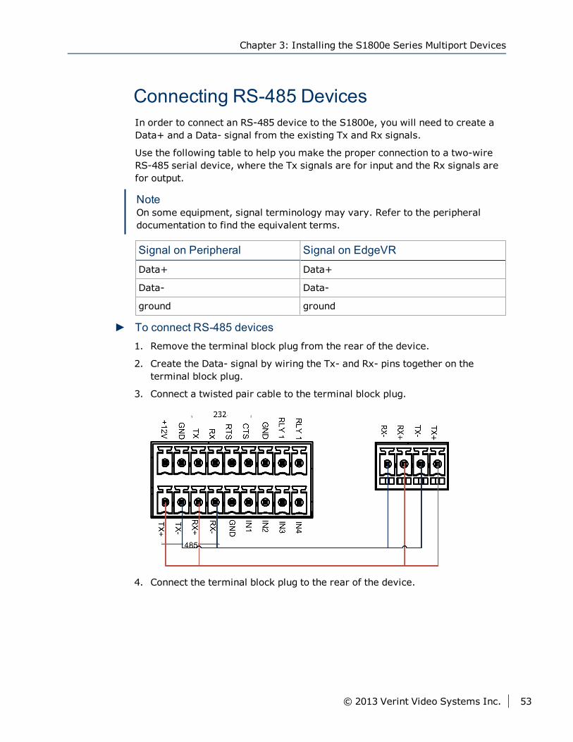
Connecting RS-485 DevicesIn order to connect an RS-485 device to the S1800e, you will need to create aData+ and a Data- signal from the existing Tx and Rx signals.
Use the following table to help you make the proper connection to a two-wireRS-485 serial device, where the Tx signals are for input and the Rx signals arefor output.
NoteOn some equipment, signal terminology may vary. Refer to the peripheraldocumentation to find the equivalent terms.
Signal on Peripheral Signal on EdgeVR
Data+ Data+
Data- Data-
ground ground
► To connect RS-485 devices1. Remove the terminal block plug from the rear of the device.
2. Create the Data- signal by wiring the Tx- and Rx- pins together on theterminal block plug.
3. Connect a twisted pair cable to the terminal block plug.
4. Connect the terminal block plug to the rear of the device.
Chapter 2: Installing the Single-and Dual-Port Devices
© 2013 Verint Video Systems Inc. 42
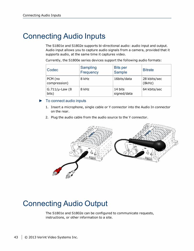
Connecting Audio InputsThe S1801e and S1802e supports bi-directional audio: audio input and output.Audio input allows you to capture audio signals from a camera, provided that itsupports audio, at the same time it captures video.
Currently, the S1800e series devices support the following audio formats:
Codec SamplingFrequency
Bits perSample Bitrate
PCM (nocompression)
8 kHz 16bits/data 28 kbits/sec(8kHz)
G.711/μ-Law (8bits)
8 kHz 14 bitssigned/data
64 kbits/sec
► To connect audio inputs1. Insert a microphone, single cable or Y connector into the Audio In connector
on the rear.
2. Plug the audio cable from the audio source to the Y connector.
Connecting Audio OutputThe S1801e and S1802e can be configured to communicate requests,instructions, or other information to a site.
Connecting Audio Inputs
43 © 2013 Verint Video Systems Inc.
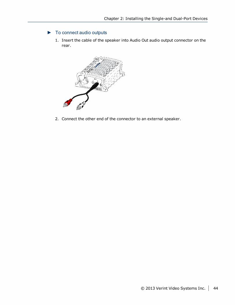
► To connect audio outputs1. Insert the cable of the speaker into Audio Out audio output connector on the
rear.
2. Connect the other end of the connector to an external speaker.
Chapter 2: Installing the Single-and Dual-Port Devices
© 2013 Verint Video Systems Inc. 44
This chapter describes the installation and configuration steps you need toperform to prepare the S1800e series devices for operation.
CautionThe S1800e series devices are enclosed in a non-weatherproof steel casingand should be placed in an indoor environment.
The following topics are discussed:
Package Contents 46
Installing on a Flat Surface 46
Installing in a Rack 47
Powering the Multiport Devices 48
Connecting Analog Cameras 49
Connecting Network Cables 50
Connecting a Serial Device 50
Connecting Audio Inputs 54
Connecting Audio Output 54
Chapter 3Chapter 3: Installing the S1800e Series
Multiport Devices
Package ContentsEach installation kit contains the following:
One S1808e, S1808e-A, S1816e, S1816e-A, S1816e-SP or S1816e-SR device
One set of rack-mount brackets with four screws (Philips M3 × 6mm panhead)
One Nextiva S1800e series Quick Installation Guide
Optional AccessoriesYou can order the following power supplies when purchasing the multiportencoders:
PS1261: Efficiency level V compliant power supply for S1800e seriesmultiport devices.
PS1281: 19-inch rack mountable power supply for up to ten multiportdevices.
PS1282-10: 19-inch rack mountable power supply for up to 10 - S1800eseries multiport devices.
PS1282-20: 19-inch rack mountable power supply for up to 20 - S1800eseries multiport devices.
PDP10-2: 19-inch 1U power distribution panel rack mount to connect up toten S1800e series devices
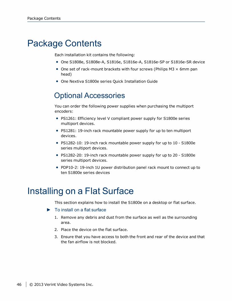
Installing on a Flat SurfaceThis section explains how to install the S1800e on a desktop or flat surface.
► To install on a flat surface1. Remove any debris and dust from the surface as well as the surrounding
area.
2. Place the device on the flat surface.
3. Ensure that you have access to both the front and rear of the device and thatthe fan airflow is not blocked.
Package Contents
46 © 2013 Verint Video Systems Inc.
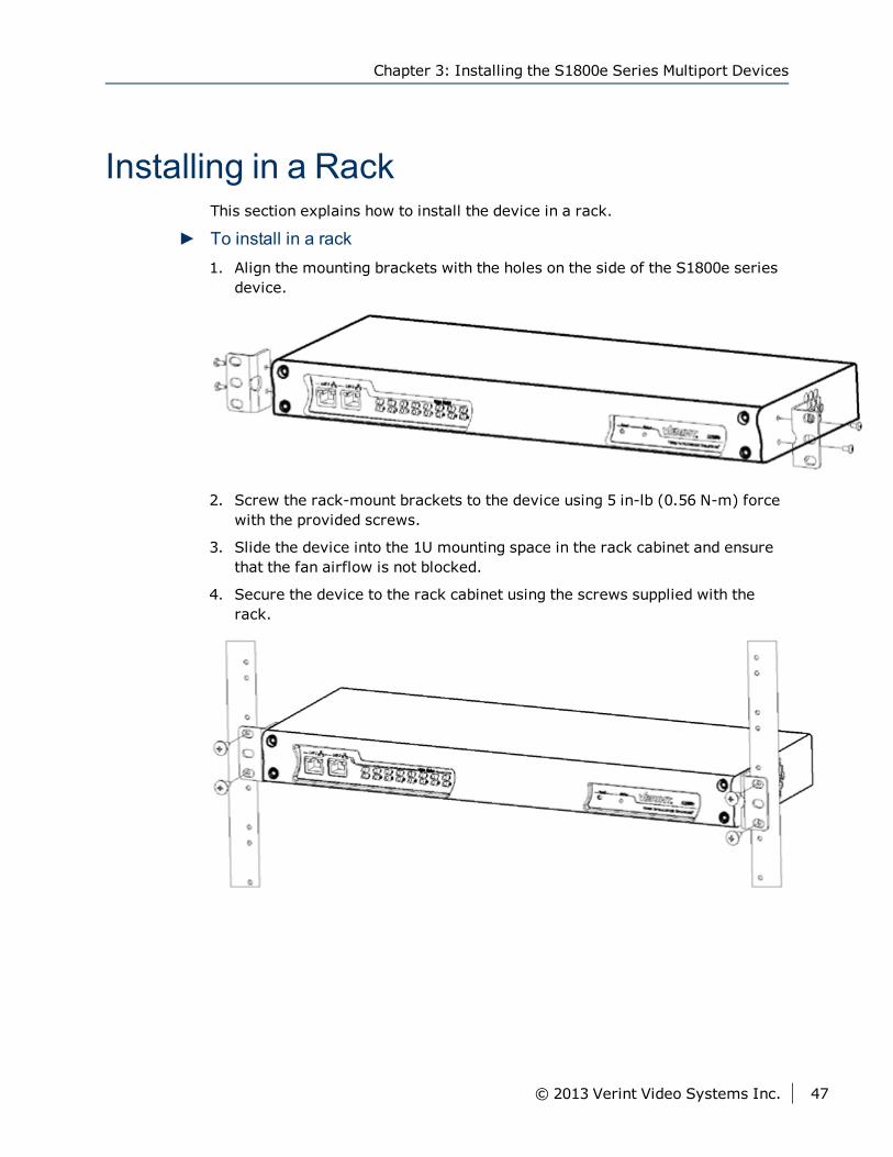
Installing in a RackThis section explains how to install the device in a rack.
► To install in a rack1. Align the mounting brackets with the holes on the side of the S1800e series
device.
2. Screw the rack-mount brackets to the device using 5 in-lb (0.56 N-m) forcewith the provided screws.
3. Slide the device into the 1U mounting space in the rack cabinet and ensurethat the fan airflow is not blocked.
4. Secure the device to the rack cabinet using the screws supplied with therack.
Chapter 3: Installing the S1800e Series Multiport Devices
© 2013 Verint Video Systems Inc. 47
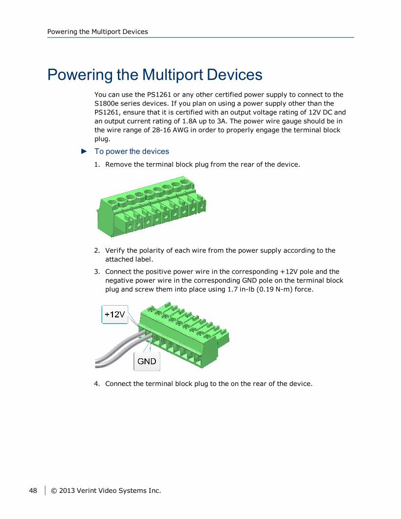
Powering the Multiport DevicesYou can use the PS1261 or any other certified power supply to connect to theS1800e series devices. If you plan on using a power supply other than thePS1261, ensure that it is certified with an output voltage rating of 12V DC andan output current rating of 1.8A up to 3A. The power wire gauge should be inthe wire range of 28-16 AWG in order to properly engage the terminal blockplug.
► To power the devices1. Remove the terminal block plug from the rear of the device.
2. Verify the polarity of each wire from the power supply according to theattached label.
3. Connect the positive power wire in the corresponding +12V pole and thenegative power wire in the corresponding GND pole on the terminal blockplug and screw them into place using 1.7 in-lb (0.19 N-m) force.
4. Connect the terminal block plug to the on the rear of the device.
Powering the Multiport Devices
48 © 2013 Verint Video Systems Inc.
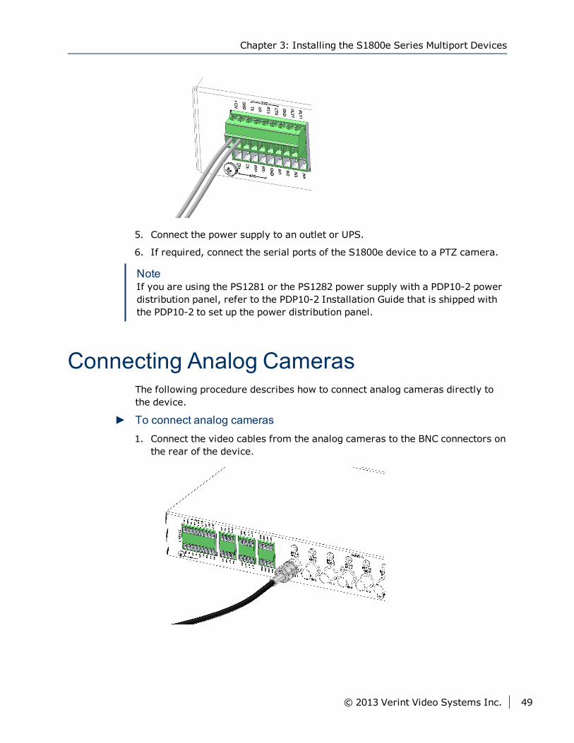
5. Connect the power supply to an outlet or UPS.
6. If required, connect the serial ports of the S1800e device to a PTZ camera.
NoteIf you are using the PS1281 or the PS1282 power supply with a PDP10-2 powerdistribution panel, refer to the PDP10-2 Installation Guide that is shipped withthe PDP10-2 to set up the power distribution panel.
Connecting Analog CamerasThe following procedure describes how to connect analog cameras directly tothe device.
► To connect analog cameras1. Connect the video cables from the analog cameras to the BNC connectors on
the rear of the device.
Chapter 3: Installing the S1800e Series Multiport Devices
© 2013 Verint Video Systems Inc. 49
Connecting Network CablesThe primary network interface (LAN-1) on the S1800e series is for the mainconnectivity to the LAN.
The secondary network interface (LAN-2) on the S1800e series encoder is usedby support for debugging purposes. The default IP address of LAN 2 is set to172.29.204.254 with subnet mask 255.255.255.252. Any computer connectingto the S1800e series encoder must use the following IP address172.29.204.253.
NoteLAN-2 is not available on the S1816e-SR model.
Connection Purpose
LAN-1 Primary LAN/WAN connectivity.
LAN-2 Secondary LAN connectivity used by Verint support.
► To connect network cables1. Plug a straight-through Ethernet cable to the LAN 1 connector on the rear.
Connecting a Serial DeviceRS-232, RS-422 and RS-485 are communication standards between a DataTerminal Equipment (DTE) and a Data Circuit-terminating Equipment (DCE)using the asynchronous serial communication method.
Most serial equipments such as PTZ cameras, keyboards, matrixs,multiplexers, or access cards conform to the RS-232 or RS-422/485 standards.The S1800e series devices supports the RS-232, RS-422, and RS-485asynchronous protocols using pluggable screw-terminal strips. For any otherprotocol, you may need a converter.
NoteThe S1800e series devices come with a terminal block plug to attach RS-232,RS-422/485 devices to the S1800e series.
Connecting Network Cables
50 © 2013 Verint Video Systems Inc.
Connecting RS-232 DevicesThe RS-232 standard is used in some analog cameras and computer serialports. Before connecting the S1800e series device to a RS-232 serialequipment, you need to determine if they are data terminal equipment (DTE) ordata communication equipment (DCE).
When connecting two modules of the same type, you have to cross the datawires to create a communication. On the other hand, when connecting a DTEwith a DCE, a straight cable is required.
► To connect RS-232 devices1. Remove the terminal block plug from the rear of the device.
2. Connect a twisted pair cable to the terminal block plug as shown below.
3. Connect the terminal block plug to the rear of the device.
Chapter 3: Installing the S1800e Series Multiport Devices
© 2013 Verint Video Systems Inc. 51
Connecting RS-422/485 Four-WiresMost target devices (keyboards, PTZ cameras, monitors) use the RS-422/485protocol for communication.
Using a twisted pair cable, connect the signals as shown in the table below.
Signal on Peripheral Signal on S1800e
Tx+ Tx+
Tx- Tx-
Rx+ Rx+
Rx- Rx-
ground ground
NoteOn some equipment, signal terminology may vary. Refer to the peripheraldocumentation to find the equivalent terms.
► To connect RS-422/485 four-wires devices1. Remove the terminal block plug from the rear of the device.
2. Connect a twisted pair cable to the terminal block plug as shown below.
3. Connect the terminal block plug to the rear of the device.
Connecting RS-422/485 Four-Wires
52 © 2013 Verint Video Systems Inc.
Connecting RS-485 DevicesIn order to connect an RS-485 device to the S1800e, you will need to create aData+ and a Data- signal from the existing Tx and Rx signals.
Use the following table to help you make the proper connection to a two-wireRS-485 serial device, where the Tx signals are for input and the Rx signals arefor output.
NoteOn some equipment, signal terminology may vary. Refer to the peripheraldocumentation to find the equivalent terms.
Signal on Peripheral Signal on EdgeVR
Data+ Data+
Data- Data-
ground ground
► To connect RS-485 devices1. Remove the terminal block plug from the rear of the device.
2. Create the Data- signal by wiring the Tx- and Rx- pins together on theterminal block plug.
3. Connect a twisted pair cable to the terminal block plug.
4. Connect the terminal block plug to the rear of the device.
Chapter 3: Installing the S1800e Series Multiport Devices
© 2013 Verint Video Systems Inc. 53
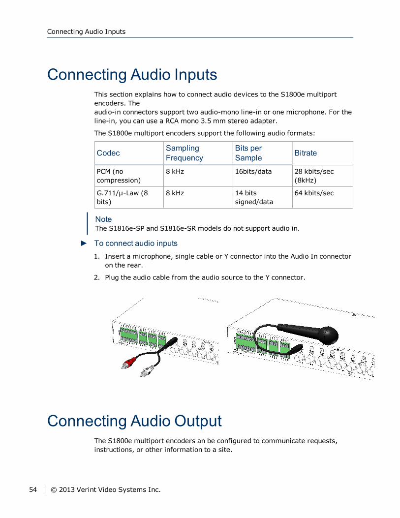
Connecting Audio InputsThis section explains how to connect audio devices to the S1800e multiportencoders. Theaudio-in connectors support two audio-mono line-in or one microphone. For theline-in, you can use a RCA mono 3.5 mm stereo adapter.
The S1800e multiport encoders support the following audio formats:
Codec SamplingFrequency
Bits perSample Bitrate
PCM (nocompression)
8 kHz 16bits/data 28 kbits/sec(8kHz)
G.711/μ-Law (8bits)
8 kHz 14 bitssigned/data
64 kbits/sec
NoteThe S1816e-SP and S1816e-SR models do not support audio in.
► To connect audio inputs1. Insert a microphone, single cable or Y connector into the Audio In connector
on the rear.
2. Plug the audio cable from the audio source to the Y connector.
Connecting Audio OutputThe S1800e multiport encoders an be configured to communicate requests,instructions, or other information to a site.
Connecting Audio Inputs
54 © 2013 Verint Video Systems Inc.
NoteThe S1816e-SP and S1816e-SR models do not support audio out.
► To connect audio outputs1. Insert the cable of the speaker into Audio Out audio output connector on the
rear.
Chapter 3: Installing the S1800e Series Multiport Devices
© 2013 Verint Video Systems Inc. 55
Once you have connected all the equipment to the device, you can beginconfiguring the device to ensure that it can communicate with the attacheddevices and with a video management software over the network. In order toconfigure the device, you first need to obtain the IP address usingSConfigurator.
SConfigurator is a PC-based administration tool that you can use over anyTCP/IP network.
CautionAny changes made using the video management software will override thechanges made using SConfigurator or the Web Interface.
The following topics are discussed:
Setting SConfigurator 57
Discovering Devices 58
IP Address Configuration 59
Configuring the Serial Ports 62
Setting the H.264 Encoding Mode for the S1816e-SP or S1816e-SR 70
Setting the Video Standard 72
Video Profile 74
Configuring the Device Video Properties 74
Configuring the Input Properties 77
Setting the SNMP Properties 78
Audio Properties 80
Chapter 4Chapter 4: Using SConfigurator for
Configuration
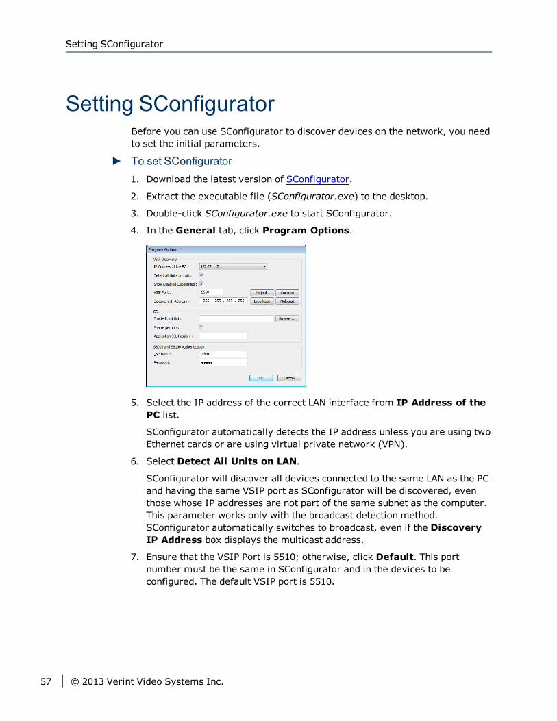
Setting SConfiguratorBefore you can use SConfigurator to discover devices on the network, you needto set the initial parameters.
► To set SConfigurator1. Download the latest version of SConfigurator.
2. Extract the executable file (SConfigurator.exe) to the desktop.
3. Double-click SConfigurator.exe to start SConfigurator.
4. In the General tab, click Program Options.
5. Select the IP address of the correct LAN interface from IP Address of thePC list.
SConfigurator automatically detects the IP address unless you are using twoEthernet cards or are using virtual private network (VPN).
6. Select Detect All Units on LAN.
SConfigurator will discover all devices connected to the same LAN as the PCand having the same VSIP port as SConfigurator will be discovered, eventhose whose IP addresses are not part of the same subnet as the computer.This parameter works only with the broadcast detection method.SConfigurator automatically switches to broadcast, even if the DiscoveryIP Address box displays the multicast address.
7. Ensure that the VSIP Port is 5510; otherwise, click Default. This portnumber must be the same in SConfigurator and in the devices to beconfigured. The default VSIP port is 5510.
Setting SConfigurator
57 © 2013 Verint Video Systems Inc.
NoteVSIP ports 9541, 65500, and those under 1024 are reserved and shouldnever be used, not even for serial port, video, or audio communication.The maximum value is 65535.
8. Ensure that the Discovery IP Address is 255.255.255.255; otherwise,click Broadcast. The communication method and associated IP addressSConfigurator will use to detect Nextiva devices on the network. Contactyour system administrator to know which method your network supports.Possible methods are:
Broadcast: Sending a message to all devices physically connected to thesame network as SConfigurator; it may not reach devices on other LANs.The broadcast IP address is 255.255.255.255. (Default).
Multicast: Sending a message to a selected group of devices. With themulticast method, SConfigurator can discover devices located acrossmultiple networks, but not through the Internet. The current multicast IPaddress is 224.16.32.1 and should not be changed.
9. Click OK.
Discovering DevicesBy default, the S1800e series devices are Dynamic Host Configuration Protocol(DHCP) enabled. Use SConfigurator to obtain the IP address of the encoder. Ifyou have a DHCP server, the encoder will automatically obtain a valid IPconfiguration.
► To discover devices1. Start SConfigurator.
2. Select the Units tab, then click Discover. The information displayed for thewill vary depending on whether your network is using a DHCP server or not.
In a DHCP environment, the Unit Name column in the Units box displaysthe model name and a unique alpha-numeric value that corresponds to theMAC address of the encoder.
Chapter 4: Using SConfigurator for Configuration
© 2013 Verint Video Systems Inc. 58
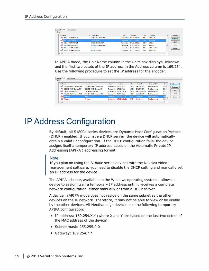
In APIPA mode, the Unit Name column in the Units box displays Unknownand the first two octets of the IP address in the Address column is 169.254.Use the following procedure to set the IP address for the encoder.
IP Address ConfigurationBy default, all S1800e series devices are Dynamic Host Configuration Protocol(DHCP ) enabled. If you have a DHCP server, the device will automaticallyobtain a valid IP configuration. If the DHCP configuration fails, the deviceassigns itself a temporary IP address based on the Automatic Private IPAddressing (APIPA ) addressing format.
NoteIf you plan on using the S1800e series devices with the Nextiva videomanagement software, you need to disable the DHCP setting and manually setan IP address for the device.
The APIPA scheme, available on the Windows operating systems, allows adevice to assign itself a temporary IP address until it receives a completenetwork configuration, either manually or from a DHCP server.
A device in APIPA mode does not reside on the same subnet as the otherdevices on the IP network. Therefore, it may not be able to view or be visibleby the other devices. All Nextiva edge devices use the following temporaryAPIPA configuration:
IP address: 169.254.X.Y (where X and Y are based on the last two octets ofthe MAC address of the device)
Subnet mask: 255.255.0.0
Gateway: 169.254.*.*
IP Address Configuration
59 © 2013 Verint Video Systems Inc.
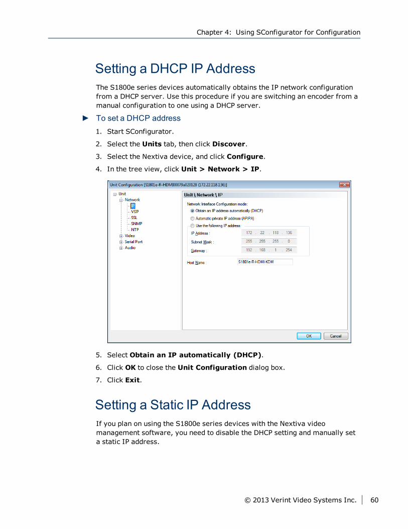
Setting a DHCP IP AddressThe S1800e series devices automatically obtains the IP network configurationfrom a DHCP server. Use this procedure if you are switching an encoder from amanual configuration to one using a DHCP server.
► To set a DHCP address1. Start SConfigurator.
2. Select the Units tab, then click Discover.
3. Select the Nextiva device, and click Configure.
4. In the tree view, click Unit > Network > IP.
5. Select Obtain an IP automatically (DHCP).
6. Click OK to close the Unit Configuration dialog box.
7. Click Exit.
Setting a Static IP AddressIf you plan on using the S1800e series devices with the Nextiva videomanagement software, you need to disable the DHCP setting and manually seta static IP address.
Chapter 4: Using SConfigurator for Configuration
© 2013 Verint Video Systems Inc. 60
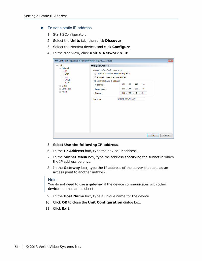
► To set a static IP address1. Start SConfigurator.
2. Select the Units tab, then click Discover.
3. Select the Nextiva device, and click Configure.
4. In the tree view, click Unit > Network > IP.
5. Select Use the following IP address.
6. In the IP Address box, type the device IP address.
7. In the Subnet Mask box, type the address specifying the subnet in whichthe IP address belongs.
8. In the Gateway box, type the IP address of the server that acts as anaccess point to another network.
NoteYou do not need to use a gateway if the device communicates with otherdevices on the same subnet.
9. In the Host Name box, type a unique name for the device.
10. Click OK to close the Unit Configuration dialog box.
11. Click Exit.
Setting a Static IP Address
61 © 2013 Verint Video Systems Inc.
Configuring the Serial PortsOnce the serial equipment is connected to the device, you need to ensure thatboth devices can communicate with each other.
NoteFor complete information about serial port parameters and the settings to use,refer to the serial equipment documentation or contact the productmanufacturer.
Configuring the RS-232 Serial Port UsingSConfiguratorUse the following procedure to configure an RS-232 device using SConfigurator.
Chapter 4: Using SConfigurator for Configuration
© 2013 Verint Video Systems Inc. 62

► To configure the RS-232 port
Configuring the RS-232 Serial Port Using SConfigurator
63 © 2013 Verint Video Systems Inc.

1. Start SConfigurator.
2. Select the Units tab, then click Discover.
3. Select the Nextiva device, and click Configure.
4. In the tree view, click Unit > Serial Port.
Chapter 4: Using SConfigurator for Configuration
© 2013 Verint Video Systems Inc. 64
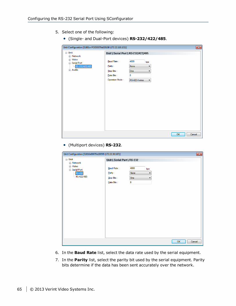
5. Select one of the following:
(Single- and Dual-Port devices) RS-232/422/485.
(Multiport devices) RS-232.
6. In the Baud Rate list, select the data rate used by the serial equipment.
7. In the Parity list, select the parity bit used by the serial equipment. Paritybits determine if the data has been sent accurately over the network.
Configuring the RS-232 Serial Port Using SConfigurator
65 © 2013 Verint Video Systems Inc.
8. In the Stop bits list, select the stop bits used by the serial equipment. Stopbits let the receiver know that the byte being transmitted has ended.
9. In the Data bits list, select the data bits used by the serial equipment. Databits represents the number of bits in each data that is sent over thenetwork. Eight data bits are universally used in most applications.
10. (Single- and Dual-Port devices) In the Operation Mode, select the way theserial equipment interfaces with the device.
11. Click OK to close the Unit Configuration dialog box.
12. Click Exit.
Configuring the RS-422/485 Serial PortUsing SConfiguratorUse the following procedure to configure the RS-422/485 port usingSConfigurator.
Chapter 4: Using SConfigurator for Configuration
© 2013 Verint Video Systems Inc. 66

► To configure the RS-422/485 port
Configuring the RS-422/485 Serial Port Using SConfigurator
67 © 2013 Verint Video Systems Inc.

1. Start SConfigurator.
2. Select the Units tab, then click Discover.
3. Select the Nextiva device, and click Configure.
4. In the tree view, click Unit > Serial Port.
Chapter 4: Using SConfigurator for Configuration
© 2013 Verint Video Systems Inc. 68
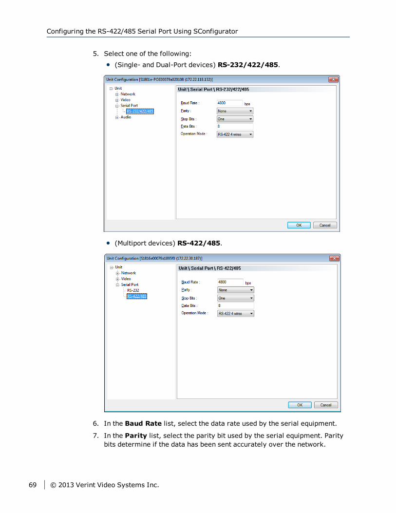
5. Select one of the following:
(Single- and Dual-Port devices) RS-232/422/485.
(Multiport devices) RS-422/485.
6. In the Baud Rate list, select the data rate used by the serial equipment.
7. In the Parity list, select the parity bit used by the serial equipment. Paritybits determine if the data has been sent accurately over the network.
Configuring the RS-422/485 Serial Port Using SConfigurator
69 © 2013 Verint Video Systems Inc.
8. In the Stop bits list, select the stop bits used by the serial equipment. Stopbits let the receiver know that the byte being transmitted has ended.
9. In the Data bits list, select the data bits used by the serial equipment. Databits represents the number of bits in each data that is sent over thenetwork. Eight data bits are universally used in most applications.
10. (Single- and Dual-Port devices) In the Operation Mode, select the way theserial equipment interfaces with the device.
11. Click OK to close the Unit Configuration dialog box.
12. Click Exit.
Setting the H.264 Encoding Mode for theS1816e-SP or S1816e-SR
The S1816e--SP and S1816e-SR supports H.264 and MPEG-4 video on all 16ports and can be configured in dual or triple stream modes. By default, theS1816e-SP is set to dual stream mode consisting of a single high-performanceH.264 stream and a single MPEG-4 stream per video input. However, you canset it to triple stream mode consisting of two H.264 streams with lowerresolution and framerate and a single MPEG-4 stream per video input.
Chapter 4: Using SConfigurator for Configuration
© 2013 Verint Video Systems Inc. 70
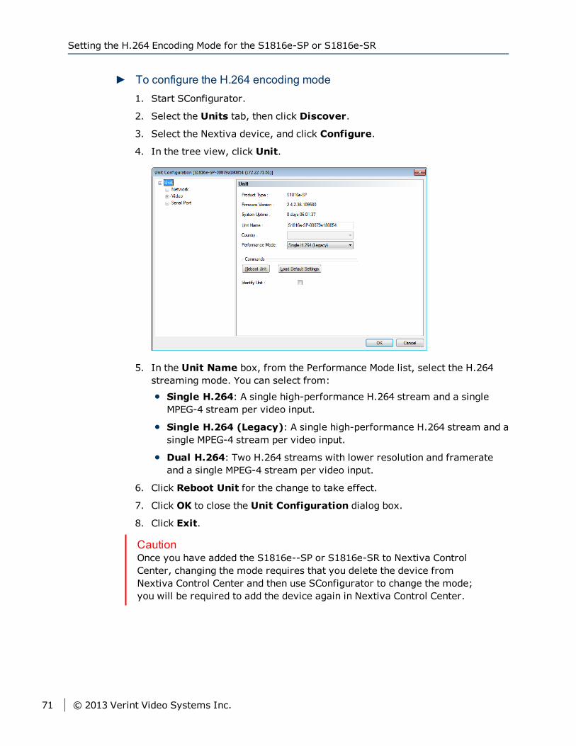
► To configure the H.264 encoding mode1. Start SConfigurator.
2. Select the Units tab, then click Discover.
3. Select the Nextiva device, and click Configure.
4. In the tree view, click Unit.
5. In the Unit Name box, from the Performance Mode list, select the H.264streaming mode. You can select from:
Single H.264: A single high-performance H.264 stream and a singleMPEG-4 stream per video input.
Single H.264 (Legacy): A single high-performance H.264 stream and asingle MPEG-4 stream per video input.
Dual H.264: Two H.264 streams with lower resolution and framerateand a single MPEG-4 stream per video input.
6. Click Reboot Unit for the change to take effect.
7. Click OK to close the Unit Configuration dialog box.
8. Click Exit.
CautionOnce you have added the S1816e--SP or S1816e-SR to Nextiva ControlCenter, changing the mode requires that you delete the device fromNextiva Control Center and then use SConfigurator to change the mode;you will be required to add the device again in Nextiva Control Center.
Setting the H.264 Encoding Mode for the S1816e-SP or S1816e-SR
71 © 2013 Verint Video Systems Inc.
Setting the Video StandardThe S1800e series device can run in one of two video standards (NTSC or PAL)and you can use different standards when deploying the devices across multiplesites. The two video standards settings are:
National Television Standards Committee (NTSC) is the standard that is used inmost of the Americas, a number of South American countries, and some Asiancountries, including Japan. NTSC uses the format of 525 picture lines and a60Hz lighting frequency.
Phase Alternation by Line (PAL) is the standard in the United Kingdom, much ofWestern Europe, several South American countries, some Middle East andAsian countries, several African countries, Australia, New Zealand, and otherPacific island countries. PAL uses the format of 625 picture lines and a 50Hzlighting frequency.
CautionYou should change the video profile settings using a video managementsoftware.
Chapter 4: Using SConfigurator for Configuration
© 2013 Verint Video Systems Inc. 72
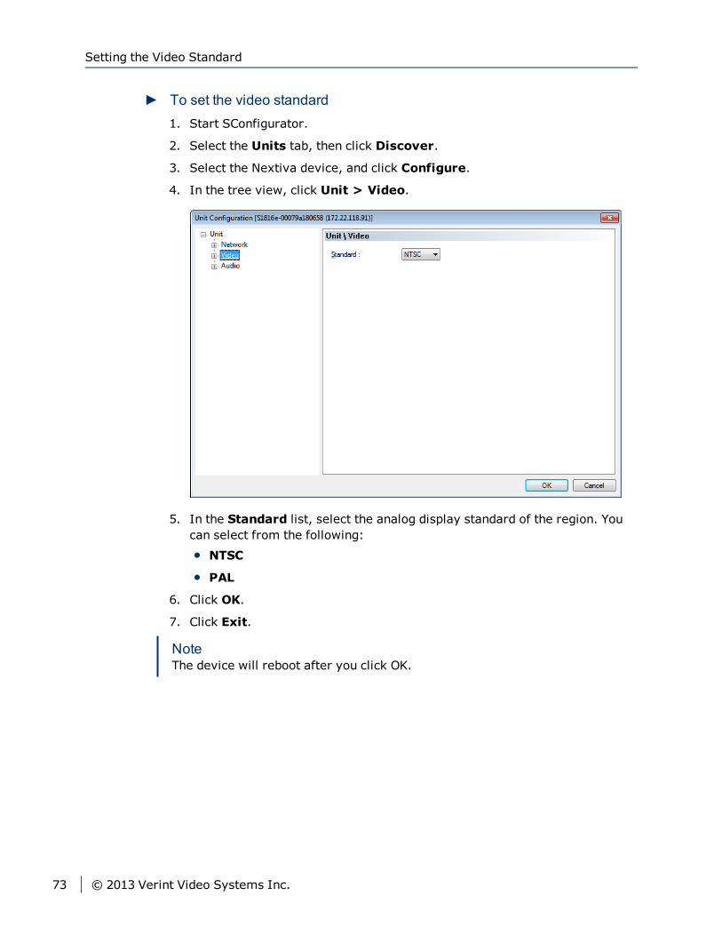
► To set the video standard1. Start SConfigurator.
2. Select the Units tab, then click Discover.
3. Select the Nextiva device, and click Configure.
4. In the tree view, click Unit > Video.
5. In the Standard list, select the analog display standard of the region. Youcan select from the following:
NTSC
PAL
6. Click OK.
7. Click Exit.
NoteThe device will reboot after you click OK.
Setting the Video Standard
73 © 2013 Verint Video Systems Inc.
Video ProfileVideo Profiles define both the quality of the video images and the storage andbandwidth requirements of the video files. All Video Profiles include at least thefollowing settings: frame rate, resolution, and bit rate. For each video input,you can configure the image parameters. With each video input, the S1800eseries devices supports up to quad-stream encoding (triple-stream encoding onthe multiport devices and quad-stream encoding on the single/dual portdevices). Encoding the video inputs provides multiple live-view streams usingdifferent sets of parameters providing high or low quality video for analysis anda single recording stream using H.264 video compression providing high qualityvideo at a substantially lower bit rates than previous standards.
NoteNextiva video management software currently supports a maximum of twostreams and provide four video profiles for the S1800e series devices. Formore information configuring video profiles, refer to the NextivaVMS Administrator Guide.
Configuring the Device Video PropertiesFor each video input, the S1800e series devices can send video with differentsets of parameters to different locations. The single/dual port devices supportquad-stream encoding with three streams using H.264 compression and oneusing MJPEG compression. The multiport devices support triple-streamencoding provides two streams using H.264 compression and one using MPEG4compression. You can customize each device in terms of frame rate andresolution to meet each system requirements.
Chapter 4: Using SConfigurator for Configuration
© 2013 Verint Video Systems Inc. 74
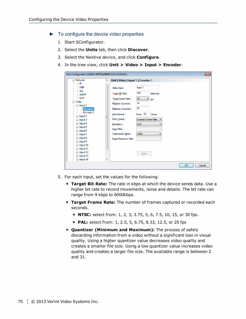
► To configure the devcie video properties1. Start SConfigurator.
2. Select the Units tab, then click Discover.
3. Select the Nextiva device, and click Configure.
4. In the tree view, click Unit > Video > Input > Encoder.
5. For each input, set the values for the following:
Target Bit Rate: The rate in kbps at which the device sends data. Use ahigher bit rate to record movements, noise and details. The bit rate canrange from 9 kbps to 6000kbps.
Target Frame Rate: The number of frames captured or recorded eachseconds.
NTSC: select from: 1, 2, 3, 3.75, 5, 6, 7.5, 10, 15, or 30 fps.
PAL: select from: 1, 2.5, 5, 6.75, 8.33, 12.5, or 25 fps
Quantizer (Minimum and Maximum): The process of safelydiscarding information from a video without a significant loss in visualquality. Using a higher quantizer value decreases video quality andcreates a smaller file size. Using a low quantizer value increases videoquality and creates a larger file size. The available range is between 2and 31.
Configuring the Device Video Properties
75 © 2013 Verint Video Systems Inc.
NoteTo maintain the video frame rate, you should set the maximum quantizerto 31. If the quality of each frame is more important, you should reducethe quantizer value; for example, a maximum quantizer of 5 keeps a goodimage quality, but skips frames when motion is high.
Intra Interval: The frequency at which a complete video frame (I-frame) is sent by the device. The available values are in the 0 – 1000range. Zero indicates that no I-frame will be sent automatically by thedevice.
Rate Control Mode: The mode controlling the bit rate variation. Theavailable modes are:
Constant Bit Rate (CBR): This mode is the most effective tomaintain the target bit rate. Video quality may suffer (frames may beskipped) and the frame rate may decrease. This mode should be usedwhen transmitting video over networks that have very limitedbandwidths, and with an intra interval value of 0 (default).
Constant Frame Rate (CFR): This mode maintains the targetframe rate. Video quality may suffer and the bit rate may exceed thetarget value.
Resolution: The total number of lines (width × height) in the videoimage. The greater the number of lines produces a more detailed,clearer and sharper image, but requires more bandwidth and storage.The following resolutions are available:
CIF: NTSC (352 × 240) and PAL (352 × 288)
2CIF: NTSC (704 × 240) and PAL (704 × 288)
4CIF: NTSC (704 × 480) and PAL (704 × 576)
D1: NTSC (720 × 486) and PAL (720 × 576)
Compression Mode: This parameter cannot be changed. Thecompression mode column displays the method of encoding currentlybeing used on the Edge device. For the multiport devices, encoders 1 and2 are set to H.264 and encoder 3 is set to MPEG4. For the single/dualdevices, encoders 1, 2 and 3 are set to H.264 and encoder 4 is set toMJPEG.
6. Click Apply.
7. Click OK.
8. Click Exit.
Chapter 4: Using SConfigurator for Configuration
© 2013 Verint Video Systems Inc. 76

Configuring the Input PropertiesThe number of video inputs varies depending on the device. For each videoinput, you can enhance the video image by adjusting the value of brightness,contrast, hue and saturation.
► To configure the input properties1. Start SConfigurator.
2. Select the Units tab, then click Discover.
3. Select the Nextiva device, and click Configure.
4. In the tree view, click Unit > Video > Input.
5. For each video settings, move the slider to the left or right to change thesetting.
Brightness: Changing the brightness level allows you to increase ordecrease highlights and shadows, making them darker or lighter. Thevalues range from -128 to 127.
Contrast: This refers to the difference between the lightest and darkestparts of the image. The values range from -128 to 127.
Hue: This refers to the color classification given to the image based onthe colors found in the color spectrum. The values range from -128 to127.
Configuring the Input Properties
77 © 2013 Verint Video Systems Inc.
Saturation: This refers to the intensity of the colors in the image. Thevalues range from -128 to 127.
6. Click OK.
7. Click Exit.
Setting the SNMP PropertiesSimple Network Management Protocol (SNMP) is a protocol used by networkmanagement systems to manage network equipments from a central location.The S1800e devices are SNMP-compliant and store data about themselves inManagement Information Bases (MIBs) and return this data (SNMP Traps) tothe SNMP requesters.
Chapter 4: Using SConfigurator for Configuration
© 2013 Verint Video Systems Inc. 78
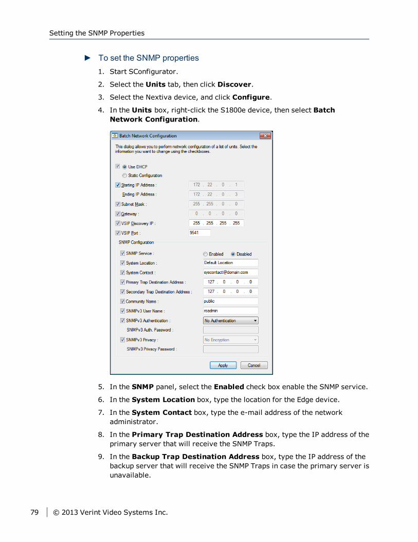
► To set the SNMP properties1. Start SConfigurator.
2. Select the Units tab, then click Discover.
3. Select the Nextiva device, and click Configure.
4. In the Units box, right-click the S1800e device, then select BatchNetwork Configuration.
5. In the SNMP panel, select the Enabled check box enable the SNMP service.
6. In the System Location box, type the location for the Edge device.
7. In the System Contact box, type the e-mail address of the networkadministrator.
8. In the Primary Trap Destination Address box, type the IP address of theprimary server that will receive the SNMP Traps.
9. In the Backup Trap Destination Address box, type the IP address of thebackup server that will receive the SNMP Traps in case the primary server isunavailable.
Setting the SNMP Properties
79 © 2013 Verint Video Systems Inc.
10. In the Community Name box, type the name of the group where you wantthe edge device to be a member.
NoteThe Edge device will only respond to requests from management servers thatbelong to the same community.
11. In the SNMPv3 User Name box, type the name of the SNMP user.
12. In the SNMPv3 User Authentication Type list, select the authenticationalgorithm for SNMP requests. You can select from the following:
No Authentication: No authentication is used.
MD5 Authentication: The Message Digest Version 5 (MD5) hashfunction is used to determine that the message is from a valid source.
SHA Authentication: The Secure Hash Algorithm (SHA) has function isused to determine that the message is from a valid source.
13. In the SNMPv3 User Auth Password box, type a password for the user.
14. In the SNMPv3 Privacy Protocol list, select the privacy protocol toencrypt the contents of the data. You can select from the following:
No Encryption: No encryption is used.
DES Encryption: The Data Encryption Standard (DES) algorithm is usedto encrypt the data.
AES Encryption: The Advanced Encryption Standard (AES) algorithm isused to encrypt the data.
15. In the SNMPv3 Privacy Password box, type a password for the privacyprotocol.
16. Click Apply.
17. Click Close.
NoteThe device will reboot.
Audio PropertiesThe S1801e, S1802e, S1808e-A and S1816e-A supports bi-directional audio:audio input and output. Audio input allows you to capture audio signals from acamera, provided that it supports audio, at the same time it captures video.
Currently, the S1800e series devices support the following audio formats:
Chapter 4: Using SConfigurator for Configuration
© 2013 Verint Video Systems Inc. 80
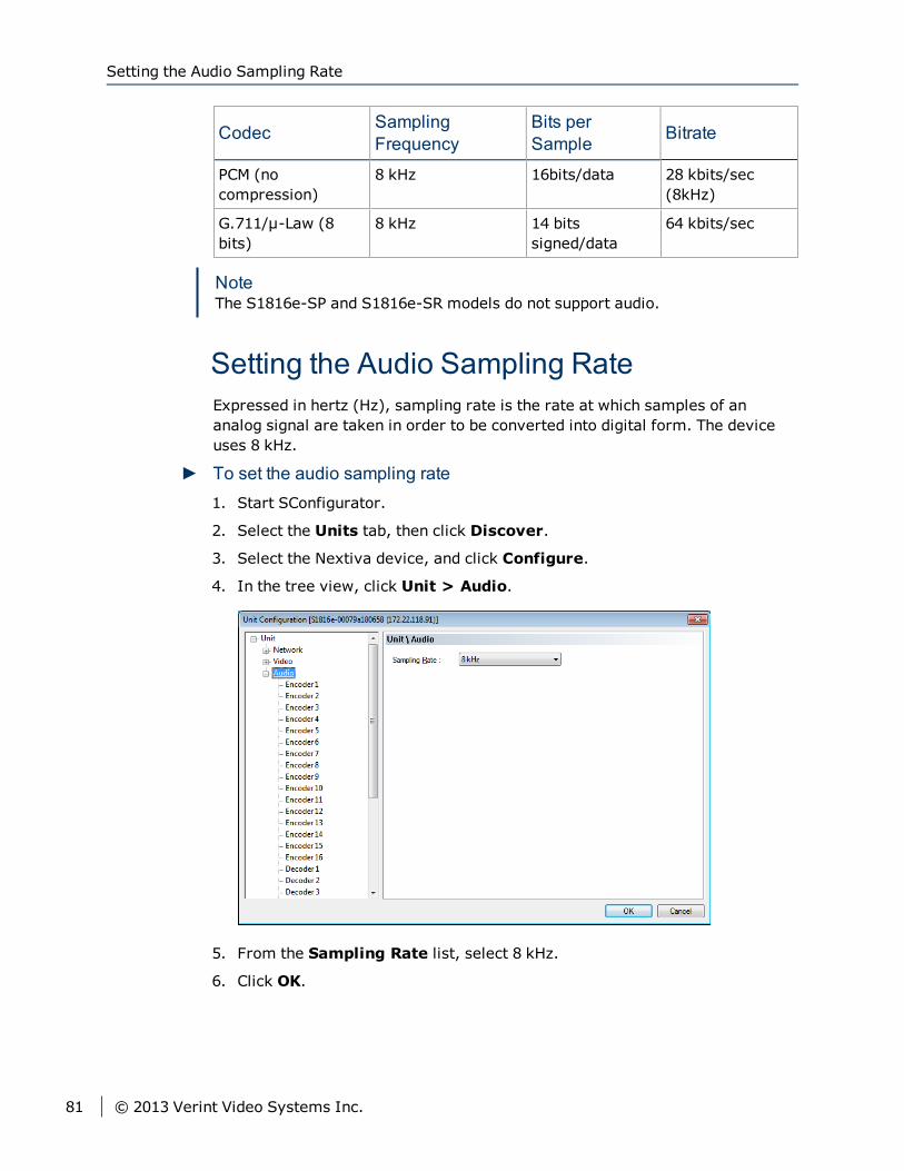
Codec SamplingFrequency
Bits perSample Bitrate
PCM (nocompression)
8 kHz 16bits/data 28 kbits/sec(8kHz)
G.711/μ-Law (8bits)
8 kHz 14 bitssigned/data
64 kbits/sec
NoteThe S1816e-SP and S1816e-SR models do not support audio.
Setting the Audio Sampling RateExpressed in hertz (Hz), sampling rate is the rate at which samples of ananalog signal are taken in order to be converted into digital form. The deviceuses 8 kHz.
► To set the audio sampling rate1. Start SConfigurator.
2. Select the Units tab, then click Discover.
3. Select the Nextiva device, and click Configure.
4. In the tree view, click Unit > Audio.
5. From the Sampling Rate list, select 8 kHz.
6. Click OK.
Setting the Audio Sampling Rate
81 © 2013 Verint Video Systems Inc.
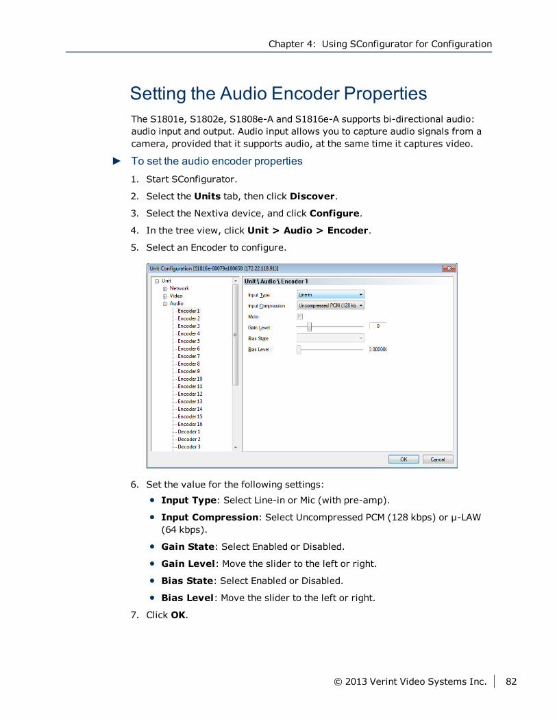
Setting the Audio Encoder PropertiesThe S1801e, S1802e, S1808e-A and S1816e-A supports bi-directional audio:audio input and output. Audio input allows you to capture audio signals from acamera, provided that it supports audio, at the same time it captures video.
► To set the audio encoder properties1. Start SConfigurator.
2. Select the Units tab, then click Discover.
3. Select the Nextiva device, and click Configure.
4. In the tree view, click Unit > Audio > Encoder.
5. Select an Encoder to configure.
6. Set the value for the following settings:
Input Type: Select Line-in or Mic (with pre-amp).
Input Compression: Select Uncompressed PCM (128 kbps) or μ-LAW(64 kbps).
Gain State: Select Enabled or Disabled.
Gain Level: Move the slider to the left or right.
Bias State: Select Enabled or Disabled.
Bias Level: Move the slider to the left or right.
7. Click OK.
Chapter 4: Using SConfigurator for Configuration
© 2013 Verint Video Systems Inc. 82
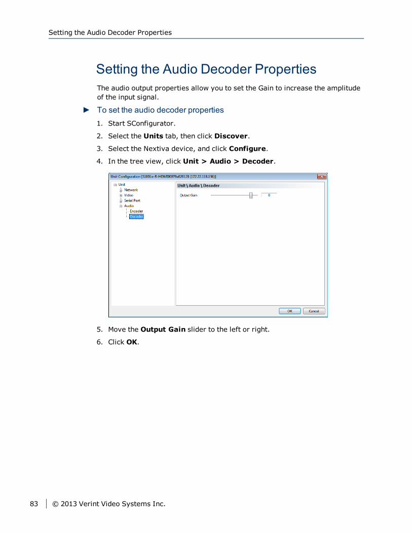
Setting the Audio Decoder PropertiesThe audio output properties allow you to set the Gain to increase the amplitudeof the input signal.
► To set the audio decoder properties1. Start SConfigurator.
2. Select the Units tab, then click Discover.
3. Select the Nextiva device, and click Configure.
4. In the tree view, click Unit > Audio > Decoder.
5. Move the Output Gain slider to the left or right.
6. Click OK.
Setting the Audio Decoder Properties
83 © 2013 Verint Video Systems Inc.
Once you have connected all the equipment to the device, you can beginconfiguring the device to ensure that it can communicate with the attacheddevices and with a video management software over the network. In order toconfigure the device, you first need to obtain the IP address usingSConfigurator.
The S1800e series devices have a self-contained web server allowing you toconnect directly to it using a web browser. The Web Interface is a browser-based tool that allows you to configure the S1800e series devices. For completeinformation on the Web Interface, refer to the Web Interface User Guide.
NoteThe default username and password for the Web Interface is admin. Werecommend that you change the default password for the Edge device to amore secure password.
The following topics are discussed:
IP Address Configuration 85
Configuring the Serial Ports 90
Setting the Video Standard 92
Video Profile 96
Setting the SNMP Properties 104
Audio Properties 107
Activating Nextiva Onboard Analytics 112
Configuring Nextiva Onboard Analytics 114
Activating Agent Vi Video Analytics 115
Configuring Agent Vi Video Analytics 117
Setting the On-Screen Display for the Decoders 118
Recording to the Storage Device 119
Chapter 5Chapter 5: Using theWeb Interface for
Configuration
IP Address ConfigurationBy default, all S1800e series devices are Dynamic Host Configuration Protocol(DHCP ) enabled. If you have a DHCP server, the device will automaticallyobtain a valid IP configuration. If the DHCP configuration fails, the deviceassigns itself a temporary IP address based on the Automatic Private IPAddressing (APIPA ) addressing format.
NoteIf you plan on using the S1800e series devices with the Nextiva videomanagement software, you need to disable the DHCP setting and manually setan IP address for the device.
The APIPA scheme, available on the Windows operating systems, allows adevice to assign itself a temporary IP address until it receives a completenetwork configuration, either manually or from a DHCP server.
A device in APIPA mode does not reside on the same subnet as the otherdevices on the IP network. Therefore, it may not be able to view or be visibleby the other devices. All Nextiva edge devices use the following temporaryAPIPA configuration:
IP address: 169.254.X.Y (where X and Y are based on the last two octets ofthe MAC address of the device)
Subnet mask: 255.255.0.0
Gateway: 169.254.*.*
Setting a DHCP IP AddressThe S1800e series devices automatically obtains the IP network configurationfrom a DHCP server. Use this procedure if you are switching an encoder from amanual configuration to one using a DHCP server.
IP Address Configuration
85 © 2013 Verint Video Systems Inc.
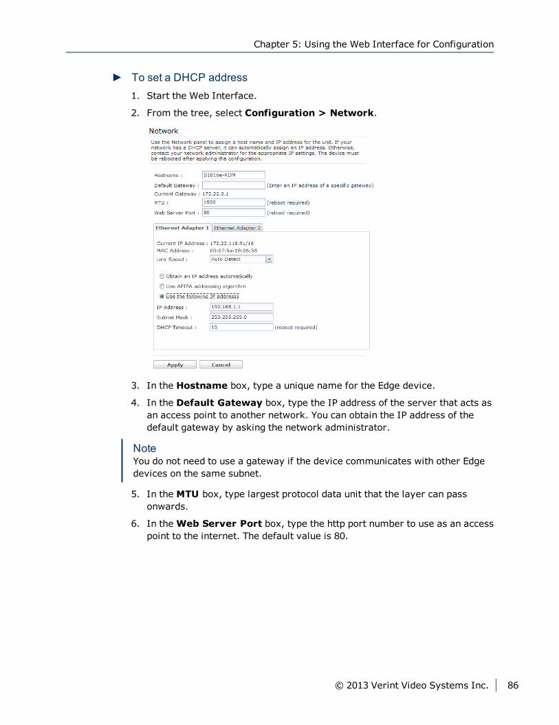
► To set a DHCP address1. Start the Web Interface.
2. From the tree, select Configuration > Network.
3. In the Hostname box, type a unique name for the Edge device.
4. In the Default Gateway box, type the IP address of the server that acts asan access point to another network. You can obtain the IP address of thedefault gateway by asking the network administrator.
NoteYou do not need to use a gateway if the device communicates with other Edgedevices on the same subnet.
5. In the MTU box, type largest protocol data unit that the layer can passonwards.
6. In theWeb Server Port box, type the http port number to use as an accesspoint to the internet. The default value is 80.
Chapter 5: Using the Web Interface for Configuration
© 2013 Verint Video Systems Inc. 86
7. In the Ethernet Adapter 1 tab:
a. In the Link Speed list, select the speed and mode of the network:
Auto detect: The unit will automatically detect the network speedand mode.
1 Gbps full duplex: The unit sends and receives 1 Gbps of data inboth directions at the same time.
1 Gbps half duplex: The unit sends and receives 1 Gbps of data inboth directions, but not at the same time.
100 Mbps full duplex: The unit sends and receives 100 Mbps ofdata in both directions at the same time.
100 Mbps half duplex: The unit sends and receives 100 Mbps ofdata in both directions, but not at the same time.
10 Mbps full duplex: The unit sends and receives 10 Mbps of datain both directions at the same time.
10 Mbps half duplex: The unit sends and receives 10 Mbps of datain both directions, but not at the same time.
NoteIf you are unsure of the network settings, select Auto detect toautomatically detect the speed and mode of the network. You can alsocontact the network administrator to provide you with the correctsettings.
b. Click Obtain an IP address automatically.
c. In the DHCP Timeout box, type the number of seconds to wait for aresponse from a DHCP server before using the APIPA address.
8. Click Apply.
NoteThe Ethernet Adapter 2 tab corresponds to LAN 2 on the S1808e, S1808e-A,S1816e, S1816e-A and S816e-SP encoders, and is used by support fordebugging purposes. The S1816e-SR model does not have a second ethernetport.
The default IP address of LAN 2 is set to 172.29.204.254 with subnet mask255.255.255.252. Any computer connecting to the S1800e multiport encodersmust use the following IP address 172.29.204.253.
Setting a Static IP AddressIf you plan on using the S1800e series devices with the Nextiva videomanagement software, you need to disable the DHCP setting and manually seta static IP address.
Setting a Static IP Address
87 © 2013 Verint Video Systems Inc.

► To set a static IP address1. Start the Web Interface.
2. From the tree, select Configuration > Network.
3. In the Hostname box, type a unique name for the Edge device.
4. In the Default Gateway box, type the IP address of the server that acts asan access point to another network. You can obtain the IP address of thedefault gateway by asking the network administrator.
NoteYou do not need to use a gateway if the device communicates with other Edgedevices on the same subnet.
5. In the MTU box, type largest protocol data unit that the layer can passonwards.
6. In theWeb Server Port box, type the http port number to use as an accesspoint to the Internet. The default value is 80.
Chapter 5: Using the Web Interface for Configuration
© 2013 Verint Video Systems Inc. 88
7. In the Ethernet Adapter 1 tab:
a. In the Link Speed list, select the speed and mode of the network:
Auto detect: The unit will automatically detect the network speedand mode.
1 Gbps full duplex: The unit sends and receives 1 Gbps of data inboth directions at the same time.
1 Gbps half duplex: The unit sends and receives 1 Gbps of data inboth directions, but not at the same time.
100 Mbps full duplex: The unit sends and receives 100 Mbps ofdata in both directions at the same time.
100 Mbps half duplex: The unit sends and receives 100 Mbps ofdata in both directions, but not at the same time.
10 Mbps full duplex: The unit sends and receives 10 Mbps of datain both directions at the same time.
10 Mbps half duplex: The unit sends and receives 10 Mbps of datain both directions, but not at the same time.
NoteIf you are unsure of the network settings, select Auto detect toautomatically detect the speed and mode of the network. You can alsocontact the network administrator to provide you with the correctsettings.
b. Click Use the following IP Address.
c. In the IP Address box, type the device IP address.
d. In the Subnet Mask box, type the address specifying the subnet inwhich the IP address belongs.
e. In the Gateway box, type the IP address of the server that acts as anaccess point to another network.
NoteYou do not need to use a gateway if the device communicates with otherdevices on the same subnet.
8. Click Apply.
Setting a Static IP Address
89 © 2013 Verint Video Systems Inc.
NoteThe Ethernet Adapter 2 tab corresponds to LAN 2 on the S1808e, S1808e-A,S1816e, S1816e-A and S816e-SP encoders, and is used by support fordebugging purposes. The S1816e-SR model does not have a second Ethernetport.
The default IP address of LAN 2 is set to 172.29.204.254 with subnet mask255.255.255.252. Any computer connecting to the S1800e multiport encodersmust use the following IP address 172.29.204.253.
Configuring the Serial PortsOnce the serial equipment is connected to the device, you need to ensure thatboth devices can communicate with each other.
NoteFor complete information about serial port parameters and the settings to use,refer to the serial equipment documentation or contact the productmanufacturer.
Configuring the RS-232 Serial PortUse the following procedure to configure an RS-232 device using the WebInterface.
Chapter 5: Using the Web Interface for Configuration
© 2013 Verint Video Systems Inc. 90
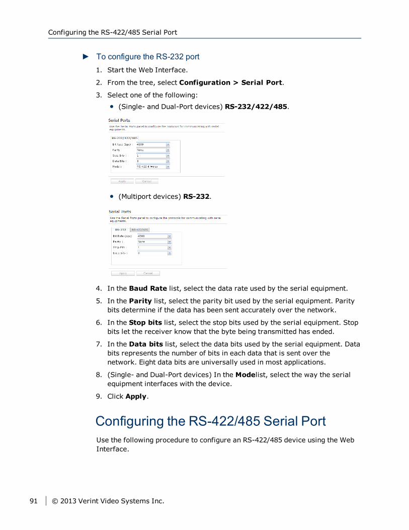
► To configure the RS-232 port1. Start the Web Interface.
2. From the tree, select Configuration > Serial Port.
3. Select one of the following:
(Single- and Dual-Port devices) RS-232/422/485.
(Multiport devices) RS-232.
4. In the Baud Rate list, select the data rate used by the serial equipment.
5. In the Parity list, select the parity bit used by the serial equipment. Paritybits determine if the data has been sent accurately over the network.
6. In the Stop bits list, select the stop bits used by the serial equipment. Stopbits let the receiver know that the byte being transmitted has ended.
7. In the Data bits list, select the data bits used by the serial equipment. Databits represents the number of bits in each data that is sent over thenetwork. Eight data bits are universally used in most applications.
8. (Single- and Dual-Port devices) In the Modelist, select the way the serialequipment interfaces with the device.
9. Click Apply.
Configuring the RS-422/485 Serial PortUse the following procedure to configure an RS-422/485 device using the WebInterface.
Configuring the RS-422/485 Serial Port
91 © 2013 Verint Video Systems Inc.
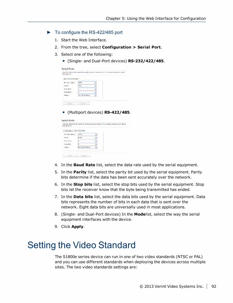
► To configure the RS-422/485 port1. Start the Web Interface.
2. From the tree, select Configuration > Serial Port.
3. Select one of the following:
(Single- and Dual-Port devices) RS-232/422/485.
(Multiport devices) RS-422/485.
4. In the Baud Rate list, select the data rate used by the serial equipment.
5. In the Parity list, select the parity bit used by the serial equipment. Paritybits determine if the data has been sent accurately over the network.
6. In the Stop bits list, select the stop bits used by the serial equipment. Stopbits let the receiver know that the byte being transmitted has ended.
7. In the Data bits list, select the data bits used by the serial equipment. Databits represents the number of bits in each data that is sent over thenetwork. Eight data bits are universally used in most applications.
8. (Single- and Dual-Port devices) In the Modelist, select the way the serialequipment interfaces with the device.
9. Click Apply.
Setting the Video StandardThe S1800e series device can run in one of two video standards (NTSC or PAL)and you can use different standards when deploying the devices across multiplesites. The two video standards settings are:
Chapter 5: Using the Web Interface for Configuration
© 2013 Verint Video Systems Inc. 92
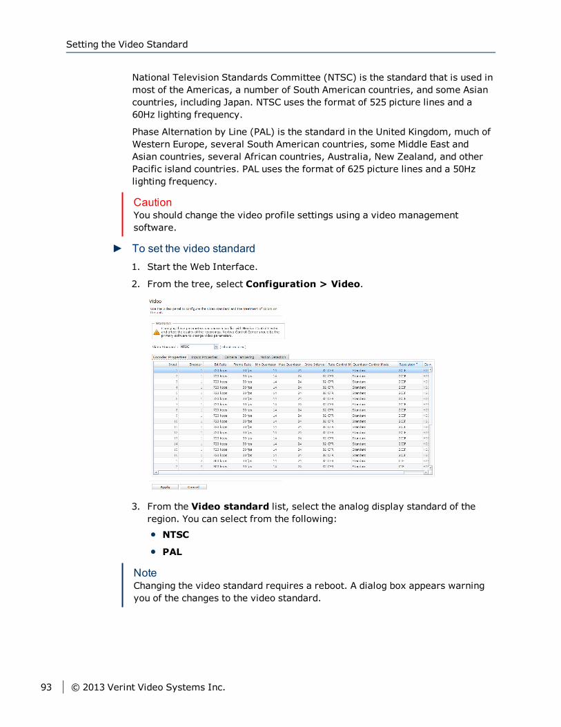
National Television Standards Committee (NTSC) is the standard that is used inmost of the Americas, a number of South American countries, and some Asiancountries, including Japan. NTSC uses the format of 525 picture lines and a60Hz lighting frequency.
Phase Alternation by Line (PAL) is the standard in the United Kingdom, much ofWestern Europe, several South American countries, some Middle East andAsian countries, several African countries, Australia, New Zealand, and otherPacific island countries. PAL uses the format of 625 picture lines and a 50Hzlighting frequency.
CautionYou should change the video profile settings using a video managementsoftware.
► To set the video standard1. Start the Web Interface.
2. From the tree, select Configuration > Video.
3. From the Video standard list, select the analog display standard of theregion. You can select from the following:
NTSC
PAL
NoteChanging the video standard requires a reboot. A dialog box appears warningyou of the changes to the video standard.
Setting the Video Standard
93 © 2013 Verint Video Systems Inc.
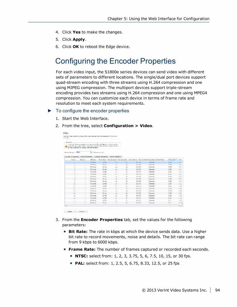
4. Click Yes to make the changes.
5. Click Apply.
6. Click OK to reboot the Edge device.
Configuring the Encoder PropertiesFor each video input, the S1800e series devices can send video with differentsets of parameters to different locations. The single/dual port devices supportquad-stream encoding with three streams using H.264 compression and oneusing MJPEG compression. The multiport devices support triple-streamencoding provides two streams using H.264 compression and one using MPEG4compression. You can customize each device in terms of frame rate andresolution to meet each system requirements.
► To configure the encoder properties1. Start the Web Interface.
2. From the tree, select Configuration > Video.
3. From the Encoder Properties tab, set the values for the followingparameters:
Bit Rate: The rate in kbps at which the device sends data. Use a higherbit rate to record movements, noise and details. The bit rate can rangefrom 9 kbps to 6000 kbps.
Frame Rate: The number of frames captured or recorded each seconds.
NTSC: select from: 1, 2, 3, 3.75, 5, 6, 7.5, 10, 15, or 30 fps.
PAL: select from: 1, 2.5, 5, 6.75, 8.33, 12.5, or 25 fps
Chapter 5: Using the Web Interface for Configuration
© 2013 Verint Video Systems Inc. 94

Quantizer (Minimum and Maximum): The process of safelydiscarding information from a video without a significant loss in visualquality. Using a higher quantizer value decreases video quality andcreates a smaller file size. Using a low quantizer value increases videoquality and creates a larger file size. The available range is between 2and 31.
NoteTo maintain the video frame rate, you should set the maximum quantizerto 31. If the quality of each frame is more important, you should reducethe quantizer value; for example, a maximum quantizer of 5 keeps a goodimage quality, but skips frames when motion is high.
Intra Interval: The frequency at which a complete video frame (I-frame) is sent by the device. The available values are in the 0 – 1000range. Zero indicates that no I-frame will be sent automatically by thedevice.
Rate Control Mode: The mode controlling the bit rate variation. Theavailable modes are:
Constant Bit Rate (CBR): This mode is the most effective tomaintain the target bit rate. Video quality may suffer (frames may beskipped) and the frame rate may decrease. This mode should be usedwhen transmitting video over networks that have very limitedbandwidths, and with an intra interval value of 0 (default).
Constant Frame Rate (CFR): This mode maintains the targetframe rate. Video quality may suffer and the bit rate may exceed thetarget value.
Quantizer Control Mode:
Standard:
High on Motion Area:
Resolution: The total number of lines (width × height) in the videoimage. The greater the number of lines produces a more detailed,clearer and sharper image, but requires more bandwidth and storage.The following resolutions are available:
CIF: NTSC (352 × 240) and PAL (352 × 288)
2CIF: NTSC (704 × 240) and PAL (704 × 288)
4CIF: NTSC (704 × 480) and PAL (704 × 576)
D1: NTSC (720 × 486) and PAL (720 × 576)
Compression Mode: This parameter cannot be changed. Thecompression mode column displays the method of encoding currentlybeing used on the Edge device. For the multiport devices, encoders 1 and2 are set to H.264 and encoder 3 is set to MPEG4. For the single/dualdevices, encoders 1, 2 and 3 are set to H.264 and encoder 4 is set to
Configuring the Encoder Properties
95 © 2013 Verint Video Systems Inc.
MJPEG.
NoteFor devices running analytics and the S1816e-SP and S1816e-SR models running in single or legacy mode, only two streams areavailable. In this case, Encoder 1 is set to H.264 and Encoder 2 is set toMPEG4.
4. Click Apply.
5. Click OK.
Video ProfileVideo Profiles define both the quality of the video images and the storage andbandwidth requirements of the video files. All Video Profiles include at least thefollowing settings: frame rate, resolution, and bit rate. For each video input,you can configure the image parameters. With each video input, the S1800eseries devices supports up to quad-stream encoding (triple-stream encoding onthe multiport devices and quad-stream encoding on the single/dual portdevices). Encoding the video inputs provides multiple live-view streams usingdifferent sets of parameters providing high or low quality video for analysis anda single recording stream using H.264 video compression providing high qualityvideo at a substantially lower bit rates than previous standards.
NoteNextiva video management software currently supports a maximum of twostreams and provide four video profiles for the S1800e series devices. Formore information configuring video profiles, refer to the NextivaVMS Administrator Guide.
Configuring the Encoder PropertiesFor each video input, the S1800e series devices can send video with differentsets of parameters to different locations. The single/dual port devices supportquad-stream encoding with three streams using H.264 compression and oneusing MJPEG compression. The multiport devices support triple-streamencoding provides two streams using H.264 compression and one using MPEG4compression. You can customize each device in terms of frame rate andresolution to meet each system requirements.
Chapter 5: Using the Web Interface for Configuration
© 2013 Verint Video Systems Inc. 96
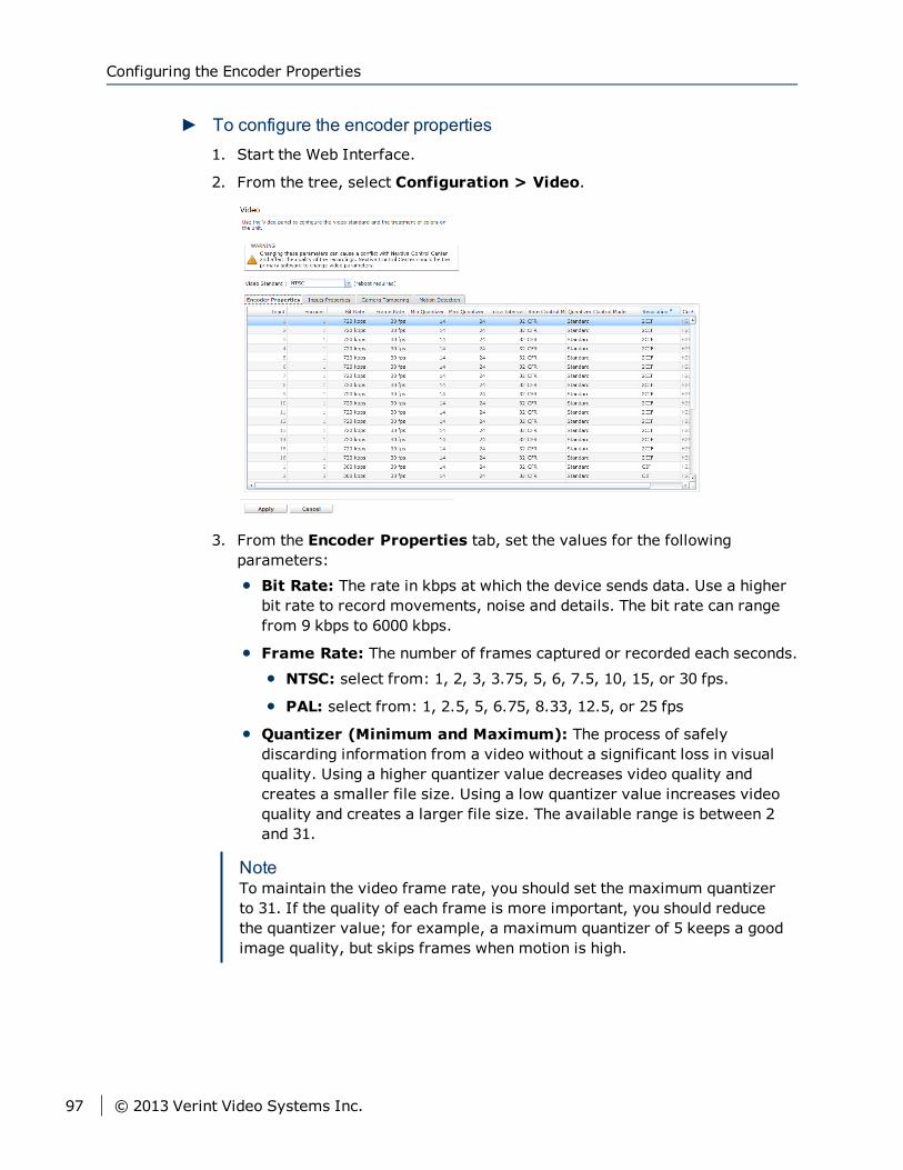
► To configure the encoder properties1. Start the Web Interface.
2. From the tree, select Configuration > Video.
3. From the Encoder Properties tab, set the values for the followingparameters:
Bit Rate: The rate in kbps at which the device sends data. Use a higherbit rate to record movements, noise and details. The bit rate can rangefrom 9 kbps to 6000 kbps.
Frame Rate: The number of frames captured or recorded each seconds.
NTSC: select from: 1, 2, 3, 3.75, 5, 6, 7.5, 10, 15, or 30 fps.
PAL: select from: 1, 2.5, 5, 6.75, 8.33, 12.5, or 25 fps
Quantizer (Minimum and Maximum): The process of safelydiscarding information from a video without a significant loss in visualquality. Using a higher quantizer value decreases video quality andcreates a smaller file size. Using a low quantizer value increases videoquality and creates a larger file size. The available range is between 2and 31.
NoteTo maintain the video frame rate, you should set the maximum quantizerto 31. If the quality of each frame is more important, you should reducethe quantizer value; for example, a maximum quantizer of 5 keeps a goodimage quality, but skips frames when motion is high.
Configuring the Encoder Properties
97 © 2013 Verint Video Systems Inc.

Intra Interval: The frequency at which a complete video frame (I-frame) is sent by the device. The available values are in the 0 – 1000range. Zero indicates that no I-frame will be sent automatically by thedevice.
Rate Control Mode: The mode controlling the bit rate variation. Theavailable modes are:
Constant Bit Rate (CBR): This mode is the most effective tomaintain the target bit rate. Video quality may suffer (frames may beskipped) and the frame rate may decrease. This mode should be usedwhen transmitting video over networks that have very limitedbandwidths, and with an intra interval value of 0 (default).
Constant Frame Rate (CFR): This mode maintains the targetframe rate. Video quality may suffer and the bit rate may exceed thetarget value.
Quantizer Control Mode:
Standard:
High on Motion Area:
Resolution: The total number of lines (width × height) in the videoimage. The greater the number of lines produces a more detailed,clearer and sharper image, but requires more bandwidth and storage.The following resolutions are available:
CIF: NTSC (352 × 240) and PAL (352 × 288)
2CIF: NTSC (704 × 240) and PAL (704 × 288)
4CIF: NTSC (704 × 480) and PAL (704 × 576)
D1: NTSC (720 × 486) and PAL (720 × 576)
Compression Mode: This parameter cannot be changed. Thecompression mode column displays the method of encoding currentlybeing used on the Edge device. For the multiport devices, encoders 1 and2 are set to H.264 and encoder 3 is set to MPEG4. For the single/dualdevices, encoders 1, 2 and 3 are set to H.264 and encoder 4 is set toMJPEG.
NoteFor devices running analytics and the S1816e-SP and S1816e-SR models running in single or legacy mode, only two streams areavailable. In this case, Encoder 1 is set to H.264 and Encoder 2 is set toMPEG4.
4. Click Apply.
5. Click OK.
Chapter 5: Using the Web Interface for Configuration
© 2013 Verint Video Systems Inc. 98
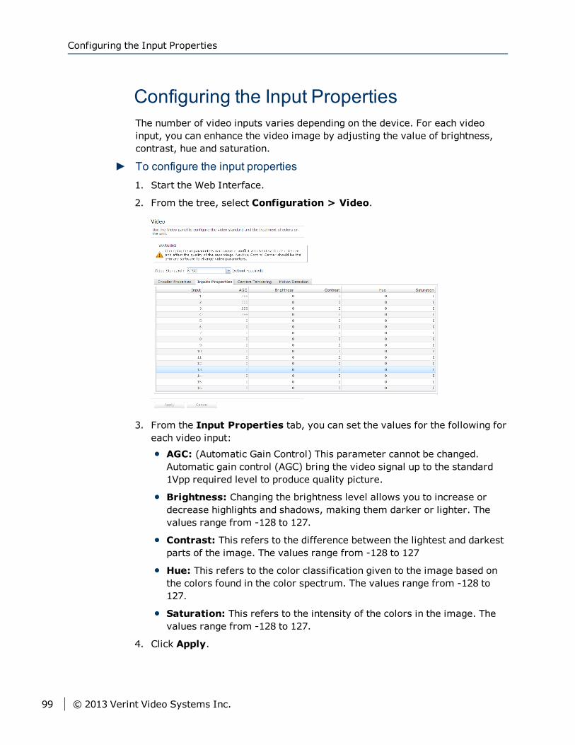
Configuring the Input PropertiesThe number of video inputs varies depending on the device. For each videoinput, you can enhance the video image by adjusting the value of brightness,contrast, hue and saturation.
► To configure the input properties1. Start the Web Interface.
2. From the tree, select Configuration > Video.
3. From the Input Properties tab, you can set the values for the following foreach video input:
AGC: (Automatic Gain Control) This parameter cannot be changed.Automatic gain control (AGC) bring the video signal up to the standard1Vpp required level to produce quality picture.
Brightness: Changing the brightness level allows you to increase ordecrease highlights and shadows, making them darker or lighter. Thevalues range from -128 to 127.
Contrast: This refers to the difference between the lightest and darkestparts of the image. The values range from -128 to 127
Hue: This refers to the color classification given to the image based onthe colors found in the color spectrum. The values range from -128 to127.
Saturation: This refers to the intensity of the colors in the image. Thevalues range from -128 to 127.
4. Click Apply.
Configuring the Input Properties
99 © 2013 Verint Video Systems Inc.
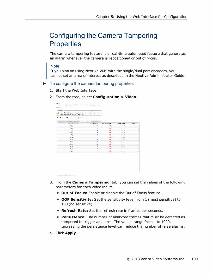
Configuring the Camera TamperingPropertiesThe camera tampering feature is a real-time automated feature that generatesan alarm whenever the camera is repositioned or out of focus.
NoteIf you plan on using Nextiva VMS with the single/dual port encoders, youcannot set an area of interest as described in the Nextiva Administrator Guide.
► To configure the camera tampering properties1. Start the Web Interface.
2. From the tree, select Configuration > Video.
3. From the Camera Tampering tab, you can set the values of the followingparameters for each video input:
Out of Focus: Enable or disable the Out of Focus feature.
OOF Sensitivity: Set the sensitivity level from 1 (most sensitive) to100 (no sensitive).
Refresh Rate: Set the refresh rate in frames per seconds.
Persistence: The number of analyzed frames that must be detected astampered to trigger an alarm. The values range from 1 to 1000.Increasing the persistence level can reduce the number of false alarms.
4. Click Apply.
Chapter 5: Using the Web Interface for Configuration
© 2013 Verint Video Systems Inc. 100

Configuring the Motion Detection PropertiesThe S1800e encoders support motion detection on each video input. For eachvideo input, you can configure the motion detection settings by adjusting thevalues for each input.
CautionYou must have a good understanding of video technology to use thesesettings. If you are unsure do not modify these settings.
► To configure the motion detection properties1. Start the Web Interface.
2. From the tree, select Configuration > Video.
3. From the Motion Detection tab, you can set the values of the followingparameters for each video input:
State: Enable or disable motion detection on the video input.
Mask State: Enable or disable the use of the mask for motion detection.If disabled, all macroblocks in the frame are checked for motion.
Mask: Type the numerical string to specify which macroblocks that willbe analyzed for motion. An empty string indicates that all macroblocks inthe frame is checked.
Upper Thresh: The minimum number of macroblocks with motion in aframe to start an alert. This value must be greater than or equal toLower Thresh. The values range from 1 to 1320 (NTSC) or 1 to 1548(PAL).
Configuring the Motion Detection Properties
101 © 2013 Verint Video Systems Inc.
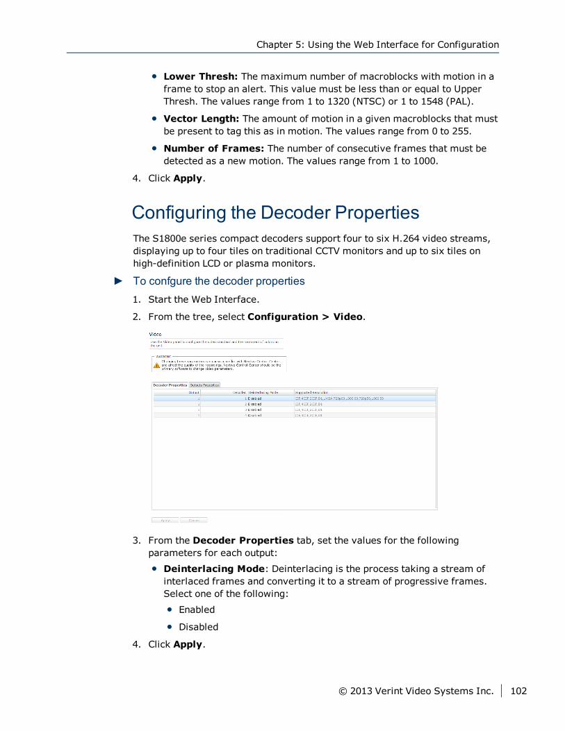
Lower Thresh: The maximum number of macroblocks with motion in aframe to stop an alert. This value must be less than or equal to UpperThresh. The values range from 1 to 1320 (NTSC) or 1 to 1548 (PAL).
Vector Length: The amount of motion in a given macroblocks that mustbe present to tag this as in motion. The values range from 0 to 255.
Number of Frames: The number of consecutive frames that must bedetected as a new motion. The values range from 1 to 1000.
4. Click Apply.
Configuring the Decoder PropertiesThe S1800e series compact decoders support four to six H.264 video streams,displaying up to four tiles on traditional CCTV monitors and up to six tiles onhigh-definition LCD or plasma monitors.
► To confgure the decoder properties1. Start the Web Interface.
2. From the tree, select Configuration > Video.
3. From the Decoder Properties tab, set the values for the followingparameters for each output:
Deinterlacing Mode: Deinterlacing is the process taking a stream ofinterlaced frames and converting it to a stream of progressive frames.Select one of the following:
Enabled
Disabled
4. Click Apply.
Chapter 5: Using the Web Interface for Configuration
© 2013 Verint Video Systems Inc. 102
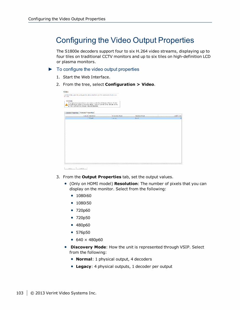
Configuring the Video Output PropertiesThe S1800e decoders support four to six H.264 video streams, displaying up tofour tiles on traditional CCTV monitors and up to six tiles on high-definition LCDor plasma monitors.
► To configure the video output properties1. Start the Web Interface.
2. From the tree, select Configuration > Video.
3. From the Output Properties tab, set the output values.
(Only on HDMI model) Resolution: The number of pixels that you candisplay on the monitor. Select from the following:
1080i60
1080i50
720p60
720p50
480p60
576p50
640 × 480p60
Discovery Mode: How the unit is represented through VSIP. Selectfrom the following:
Normal: 1 physical output, 4 decoders
Legacy: 4 physical outputs, 1 decoder per output
Configuring the Video Output Properties
103 © 2013 Verint Video Systems Inc.
Receiver Mode: The number of tiles to display on the monitor. Selectfrom the following:
Single: Video from one stream is displayed on the monitor.
Quad: The monitor is divided into four quadrants and each displayingvideo from four different streams.
3 × 2: (Only on HDMI model) The monitor displays video from sixdifferent streams.
Guard Tour: Video from each stream is displayed on the monitor oneafter another.
Dwell Time: The number of seconds to display video from a selectedcamera before switching to the next camera in the tour.
4. Click Apply.
Setting the SNMP PropertiesSimple Network Management Protocol (SNMP) is a protocol used by networkmanagement systems to manage network equipments from a central location.The S1800e devices are SNMP-compliant and store data about themselves inManagement Information Bases (MIBs) and return this data (SNMP Traps) tothe SNMP requesters.
Chapter 5: Using the Web Interface for Configuration
© 2013 Verint Video Systems Inc. 104

► To set the SNMP properties1. Start the Web Interface.
2. From the tree, select Configuration > SNMP.
3. In the SNMP panel, select the Enabled check box enable the SNMP service.
4. In the System Location box, type the location for the Edge device.
5. In the System Contact box, type the e-mail address of the networkadministrator.
6. In the Primary Trap Destination Address box, type the IP address of theprimary server that will receive the SNMP Traps.
7. In the Backup Trap Destination Address box, type the IP address of thebackup server that will receive the SNMP Traps in case the primary server isunavailable.
8. In the Community Name box, type the name of the group where you wantthe edge device to be a member.
NoteThe Edge device will only respond to requests from management servers thatbelong to the same community.
9. In the User Name box, type the name of the SNMP user.
Setting the SNMP Properties
105 © 2013 Verint Video Systems Inc.
10. In the User Authentication Type list, select the authentication algorithmfor SNMP requests. You can select from the following:
No Authentication: No authentication is used.
MD5 Authentication: The Message Digest Version 5 (MD5) hashfunction is used to determine that the message is from a valid source.
SHA Authentication: The Secure Hash Algorithm (SHA) has function isused to determine that the message is from a valid source.
11. In the User Authentication Password box, type a password for the user.
12. In the User Privacy Protocol list, select the privacy protocol to encryptthe contents of the data. You can select from the following:
No Encryption: No encryption is used.
DES Encryption: The Data Encryption Standard (DES) algorithm is usedto encrypt the data.
AES Encryption: The Advanced Encryption Standard (AES) algorithm isused to encrypt the data.
13. In the User Privacy Password box, type a password for the privacyprotocol.
14. Click Apply.
Viewing MIB InformationYou can download the device Management Information Base (MIB) and use aSNMP application to view the information. The MIB is a collection ofmanageable entities of the device network element.
The S1800e series device sends a coldStart trap when it is initialized and sendsthe following Verint-Specific SNMP traps:
Video Signal Loss edVinMediaStateAnalogNotif trap. This trap is generated ifan analog video input of an S1800e series device is disconnected orreconnected with the following information:
Input number (1 to 16 for S1816e and S1816e-SP, 1 to 8 for S1808e)
New state (0: not connected, 1: connected)
Dry Input State Change edDigitalinPinStateNotif trap. This trap is generatedif the status of a digital alarm dry contact input of the S1800e device haschanged with the following information:
Input number (1 to 16 for S1816e and S1816e-SP, 1 to 8 for S1808e)
New state (0: not connected, 1: connected)
Chapter 5: Using the Web Interface for Configuration
© 2013 Verint Video Systems Inc. 106
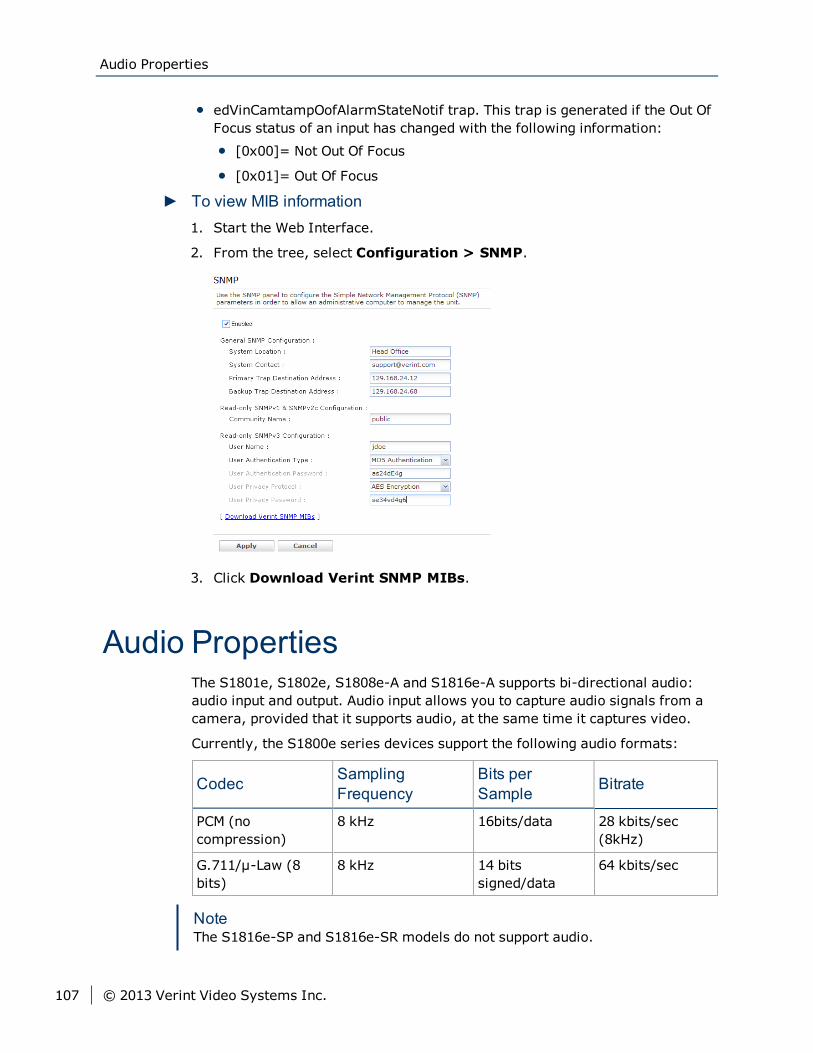
edVinCamtampOofAlarmStateNotif trap. This trap is generated if the Out OfFocus status of an input has changed with the following information:
[0x00]= Not Out Of Focus
[0x01]= Out Of Focus
► To view MIB information1. Start the Web Interface.
2. From the tree, select Configuration > SNMP.
3. Click Download Verint SNMP MIBs.
Audio PropertiesThe S1801e, S1802e, S1808e-A and S1816e-A supports bi-directional audio:audio input and output. Audio input allows you to capture audio signals from acamera, provided that it supports audio, at the same time it captures video.
Currently, the S1800e series devices support the following audio formats:
Codec SamplingFrequency
Bits perSample Bitrate
PCM (nocompression)
8 kHz 16bits/data 28 kbits/sec(8kHz)
G.711/μ-Law (8bits)
8 kHz 14 bitssigned/data
64 kbits/sec
NoteThe S1816e-SP and S1816e-SR models do not support audio.
Audio Properties
107 © 2013 Verint Video Systems Inc.
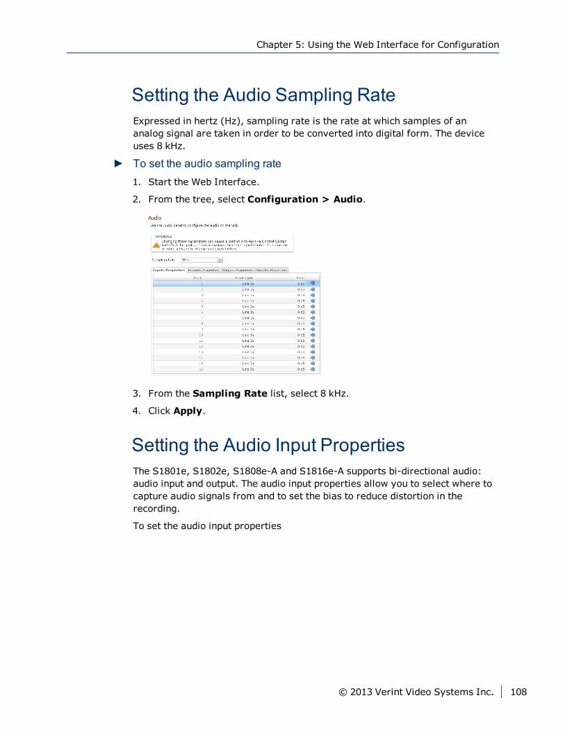
Setting the Audio Sampling RateExpressed in hertz (Hz), sampling rate is the rate at which samples of ananalog signal are taken in order to be converted into digital form. The deviceuses 8 kHz.
► To set the audio sampling rate1. Start the Web Interface.
2. From the tree, select Configuration > Audio.
3. From the Sampling Rate list, select 8 kHz.
4. Click Apply.
Setting the Audio Input PropertiesThe S1801e, S1802e, S1808e-A and S1816e-A supports bi-directional audio:audio input and output. The audio input properties allow you to select where tocapture audio signals from and to set the bias to reduce distortion in therecording.
To set the audio input properties
Chapter 5: Using the Web Interface for Configuration
© 2013 Verint Video Systems Inc. 108
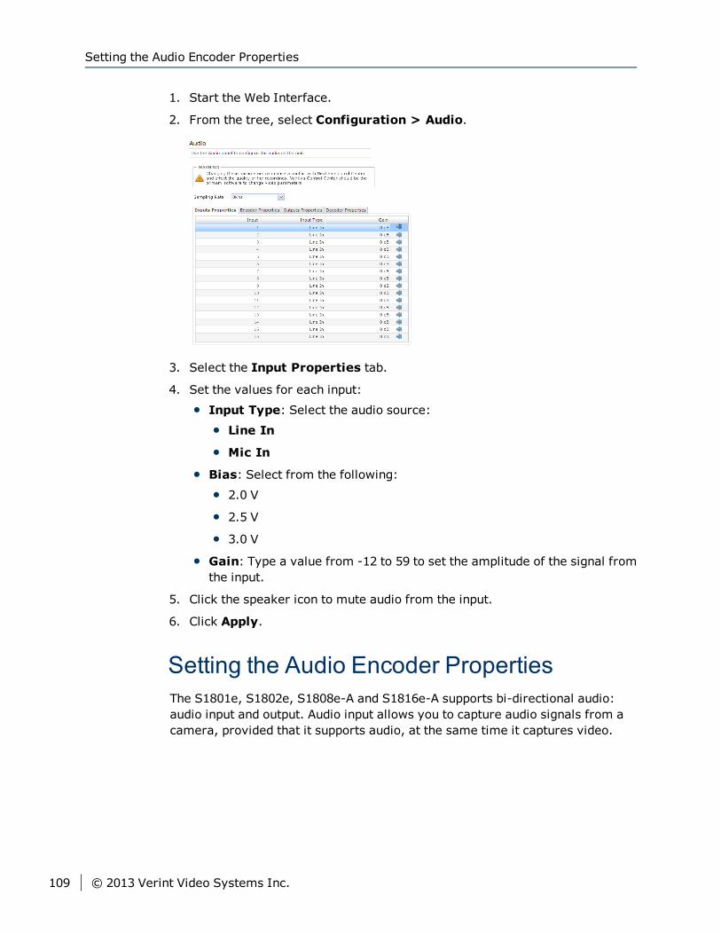
1. Start the Web Interface.
2. From the tree, select Configuration > Audio.
3. Select the Input Properties tab.
4. Set the values for each input:
Input Type: Select the audio source:
Line In
Mic In
Bias: Select from the following:
2.0 V
2.5 V
3.0 V
Gain: Type a value from -12 to 59 to set the amplitude of the signal fromthe input.
5. Click the speaker icon to mute audio from the input.
6. Click Apply.
Setting the Audio Encoder PropertiesThe S1801e, S1802e, S1808e-A and S1816e-A supports bi-directional audio:audio input and output. Audio input allows you to capture audio signals from acamera, provided that it supports audio, at the same time it captures video.
Setting the Audio Encoder Properties
109 © 2013 Verint Video Systems Inc.
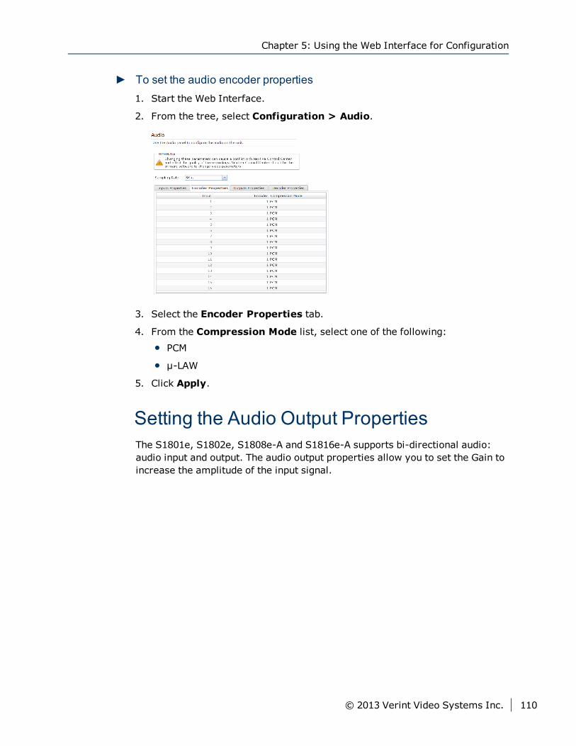
► To set the audio encoder properties1. Start the Web Interface.
2. From the tree, select Configuration > Audio.
3. Select the Encoder Properties tab.
4. From the Compression Mode list, select one of the following:
PCM
μ-LAW
5. Click Apply.
Setting the Audio Output PropertiesThe S1801e, S1802e, S1808e-A and S1816e-A supports bi-directional audio:audio input and output. The audio output properties allow you to set the Gain toincrease the amplitude of the input signal.
Chapter 5: Using the Web Interface for Configuration
© 2013 Verint Video Systems Inc. 110
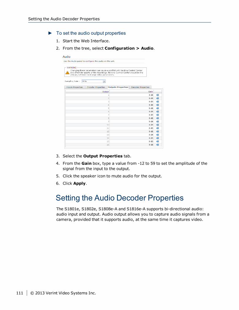
► To set the audio output properties1. Start the Web Interface.
2. From the tree, select Configuration > Audio.
3. Select the Output Properties tab.
4. From the Gain box, type a value from -12 to 59 to set the amplitude of thesignal from the input to the output.
5. Click the speaker icon to mute audio for the output.
6. Click Apply.
Setting the Audio Decoder PropertiesThe S1801e, S1802e, S1808e-A and S1816e-A supports bi-directional audio:audio input and output. Audio output allows you to capture audio signals from acamera, provided that it supports audio, at the same time it captures video.
Setting the Audio Decoder Properties
111 © 2013 Verint Video Systems Inc.
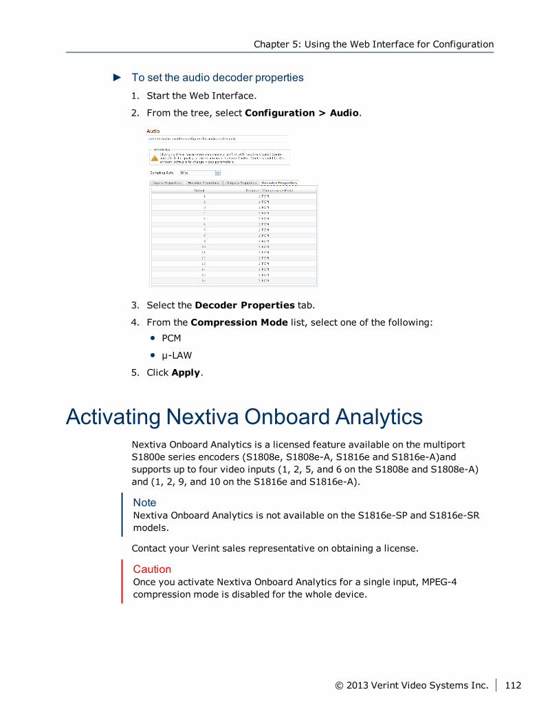
► To set the audio decoder properties1. Start the Web Interface.
2. From the tree, select Configuration > Audio.
3. Select the Decoder Properties tab.
4. From the Compression Mode list, select one of the following:
PCM
μ-LAW
5. Click Apply.
Activating Nextiva Onboard AnalyticsNextiva Onboard Analytics is a licensed feature available on the multiportS1800e series encoders (S1808e, S1808e-A, S1816e and S1816e-A)andsupports up to four video inputs (1, 2, 5, and 6 on the S1808e and S1808e-A)and (1, 2, 9, and 10 on the S1816e and S1816e-A).
NoteNextiva Onboard Analytics is not available on the S1816e-SP and S1816e-SRmodels.
Contact your Verint sales representative on obtaining a license.
CautionOnce you activate Nextiva Onboard Analytics for a single input, MPEG-4compression mode is disabled for the whole device.
Chapter 5: Using the Web Interface for Configuration
© 2013 Verint Video Systems Inc. 112
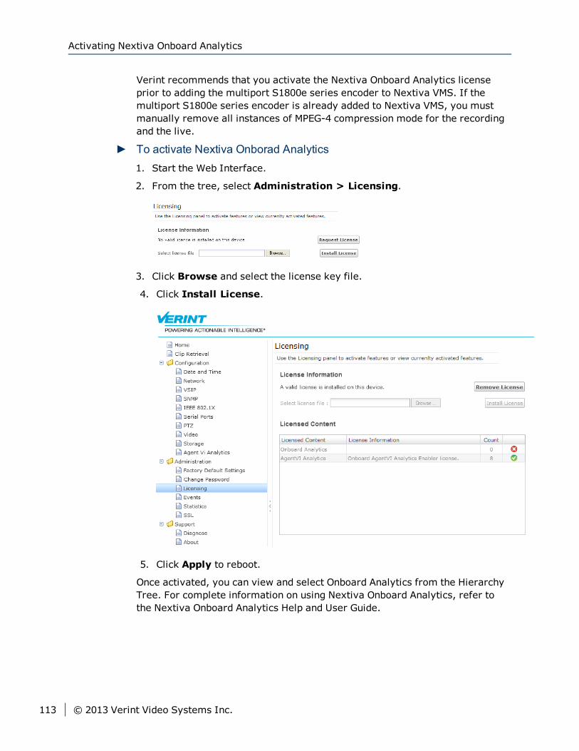
Verint recommends that you activate the Nextiva Onboard Analytics licenseprior to adding the multiport S1800e series encoder to Nextiva VMS. If themultiport S1800e series encoder is already added to Nextiva VMS, you mustmanually remove all instances of MPEG-4 compression mode for the recordingand the live.
► To activate Nextiva Onborad Analytics1. Start the Web Interface.
2. From the tree, select Administration > Licensing.
3. Click Browse and select the license key file.
4. Click Install License.
5. Click Apply to reboot.
Once activated, you can view and select Onboard Analytics from the HierarchyTree. For complete information on using Nextiva Onboard Analytics, refer tothe Nextiva Onboard Analytics Help and User Guide.
Activating Nextiva Onboard Analytics
113 © 2013 Verint Video Systems Inc.
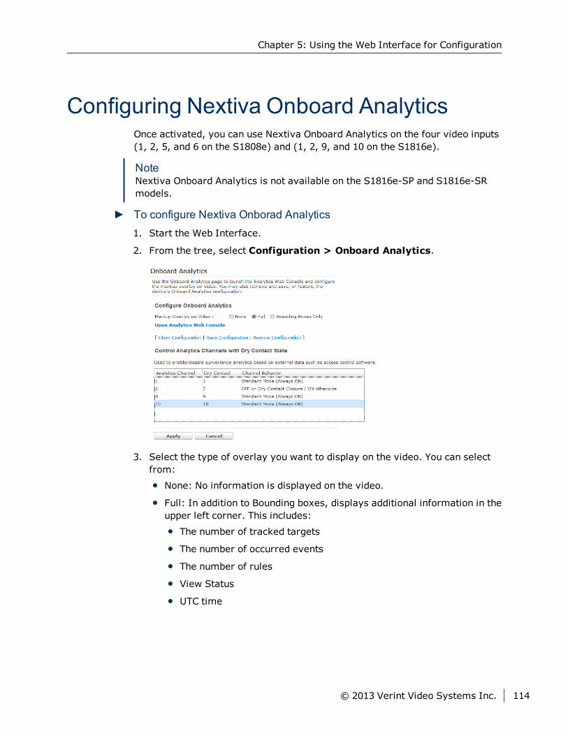
Configuring Nextiva Onboard AnalyticsOnce activated, you can use Nextiva Onboard Analytics on the four video inputs(1, 2, 5, and 6 on the S1808e) and (1, 2, 9, and 10 on the S1816e).
NoteNextiva Onboard Analytics is not available on the S1816e-SP and S1816e-SRmodels.
► To configure Nextiva Onborad Analytics1. Start the Web Interface.
2. From the tree, select Configuration > Onboard Analytics.
3. Select the type of overlay you want to display on the video. You can selectfrom:
None: No information is displayed on the video.
Full: In addition to Bounding boxes, displays additional information in theupper left corner. This includes:
The number of tracked targets
The number of occurred events
The number of rules
View Status
UTC time
Chapter 5: Using the Web Interface for Configuration
© 2013 Verint Video Systems Inc. 114
Bounding Boxes only: Displays color-coded rectangles around objectsbeing tracked. The following three colors are used:
Magenta to track People
Green to track Vehicles
Red to track objects that have triggered an alarm.
4. Click Open Analytics Web Console to configure Nextiva OnboardAnalytics. For more information using Nextiva Onboard Analytics, use thehelp.
5. Click Save Configuration to save the changes. You can always click Clearconfiguration to reset Nextiva Onboard Analytics or RestoreConfiguration if you have to revert back to the saved configuration.
6. From the Control Analytics Channels with Dry Contact State section,for each of the four analytics channels, choose what happens to OnboardAnalytics when the dry contact state changes:
Standard Mode (Always On)
OFF on Dry Contact Closure/ON otherwise
7. Click Apply to reboot the Edge device.
Activating Agent Vi Video AnalyticsAgent Vi-System™ is an alternative to the Nextiva Onboard Analyticsfunctionality already available on the multiport S1800e series encoders. TheS1808e, S1808e-A, S1816e and S1816e-A encoders are compatible with AgentVi's real-time video analytics software. A multiport encoder that is Agent Viready is able to process rules that are configured in Agent Vi-System.
NoteAgent Vi is not available on the S1816e-SP and S1816e-SR models.
A Verint license is required to make the multiport encoders Agent Vi ready andenable eight video inputs to work with Agent Vi-System. The following lists thesupported video inputs on the multiport encoders.
S1808e and S1808e-A: Inputs 1 to 8
S1816e and S1816e-A: Inputs 1, 2, 3, 4, 9, 10, 11 and 12
The Verint license is a generic key that can be used on all multiport encodersthat need to be Agent Vi ready. For more information about obtaining the Verintlicense, contact Verint support or your Verint sales representative.
Activating Agent Vi Video Analytics
115 © 2013 Verint Video Systems Inc.
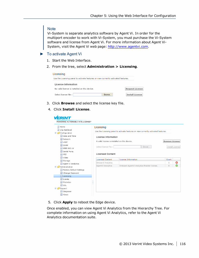
NoteVi-System is separate analytics software by Agent Vi. In order for themultiport encoder to work with Vi-System, you must purchase the Vi-Systemsoftware and license from Agent Vi. For more information about Agent Vi-System, visit the Agent Vi web page: http://www.agentvi.com.
► To activate Agent Vi1. Start the Web Interface.
2. From the tree, select Administration > Licensing.
3. Click Browse and select the license key file.
4. Click Install License.
5. Click Apply to reboot the Edge device.
Once enabled, you can view Agent Vi Analytics from the Hierarchy Tree. Forcomplete information on using Agent Vi Analytics, refer to the Agent ViAnalytics documentation suite.
Chapter 5: Using the Web Interface for Configuration
© 2013 Verint Video Systems Inc. 116
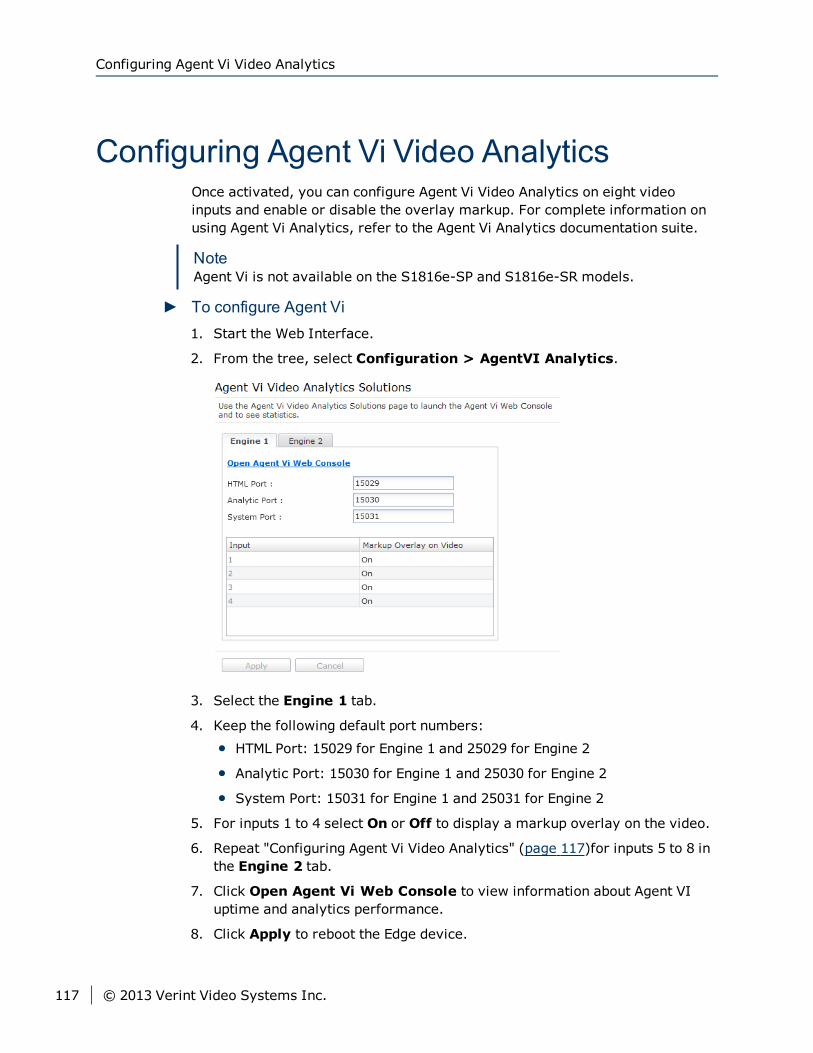
Configuring Agent Vi Video AnalyticsOnce activated, you can configure Agent Vi Video Analytics on eight videoinputs and enable or disable the overlay markup. For complete information onusing Agent Vi Analytics, refer to the Agent Vi Analytics documentation suite.
NoteAgent Vi is not available on the S1816e-SP and S1816e-SR models.
► To configure Agent Vi1. Start the Web Interface.
2. From the tree, select Configuration > AgentVI Analytics.
3. Select the Engine 1 tab.
4. Keep the following default port numbers:
HTML Port: 15029 for Engine 1 and 25029 for Engine 2
Analytic Port: 15030 for Engine 1 and 25030 for Engine 2
System Port: 15031 for Engine 1 and 25031 for Engine 2
5. For inputs 1 to 4 select On or Off to display a markup overlay on the video.
6. Repeat "Configuring Agent Vi Video Analytics" (page 117)for inputs 5 to 8 inthe Engine 2 tab.
7. Click Open Agent Vi Web Console to view information about Agent VIuptime and analytics performance.
8. Click Apply to reboot the Edge device.
Configuring Agent Vi Video Analytics
117 © 2013 Verint Video Systems Inc.
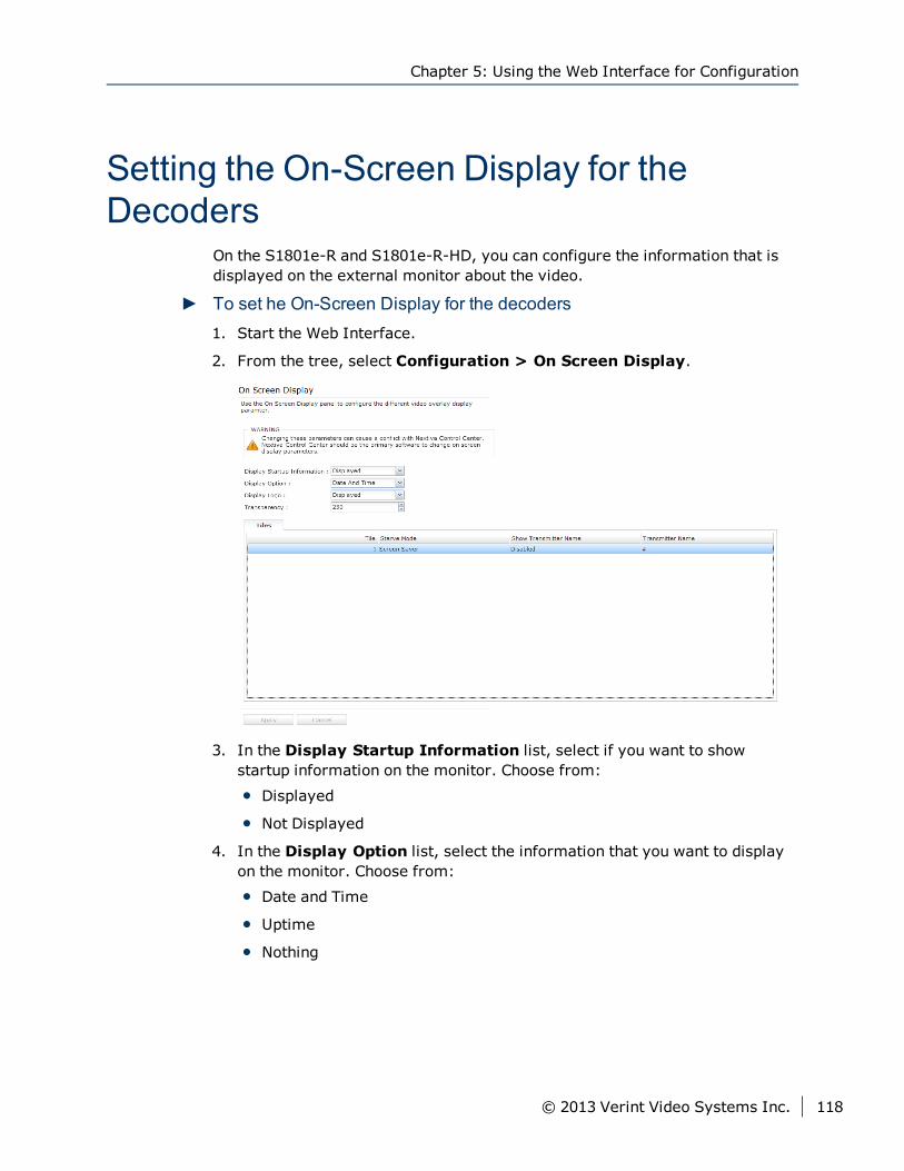
Setting the On-Screen Display for theDecoders
On the S1801e-R and S1801e-R-HD, you can configure the information that isdisplayed on the external monitor about the video.
► To set he On-Screen Display for the decoders1. Start the Web Interface.
2. From the tree, select Configuration > On Screen Display.
3. In the Display Startup Information list, select if you want to showstartup information on the monitor. Choose from:
Displayed
Not Displayed
4. In the Display Option list, select the information that you want to displayon the monitor. Choose from:
Date and Time
Uptime
Nothing
Chapter 5: Using the Web Interface for Configuration
© 2013 Verint Video Systems Inc. 118
5. In the Display Logo list, choose to show the Verint logo on the monitorduring the device start up. Choose from:
Displayed
Not Displayed
6. In the Transparency box, type a value to the set transparency level of thetext on the monitor.
7. From the Tiles tab, for each tile, set the following:
a. In the Starve Mode list, select what to display on the monitor whenthere is no video. You can select from:
Screen Saver
Black
Last Decoded Image
b. In the Show Transmitter Name list, select whether or not to show thedevice name. Choose from the following
c. In the Transmitter Name box, type the name you want to show.
8. Click Apply.
Recording to the Storage DeviceThe encoders now support storage on the edge - a failover mechanism thatensures video is recorded in case connection with the management software islost. The single- and dual-port encoders support microSD cards with amaximum capacity of 32 GB. The mulitport encoders support one USB drive.
NoteThe S1816e-SR does not support recording to a USB drive.
Recording to the Storage Device
119 © 2013 Verint Video Systems Inc.
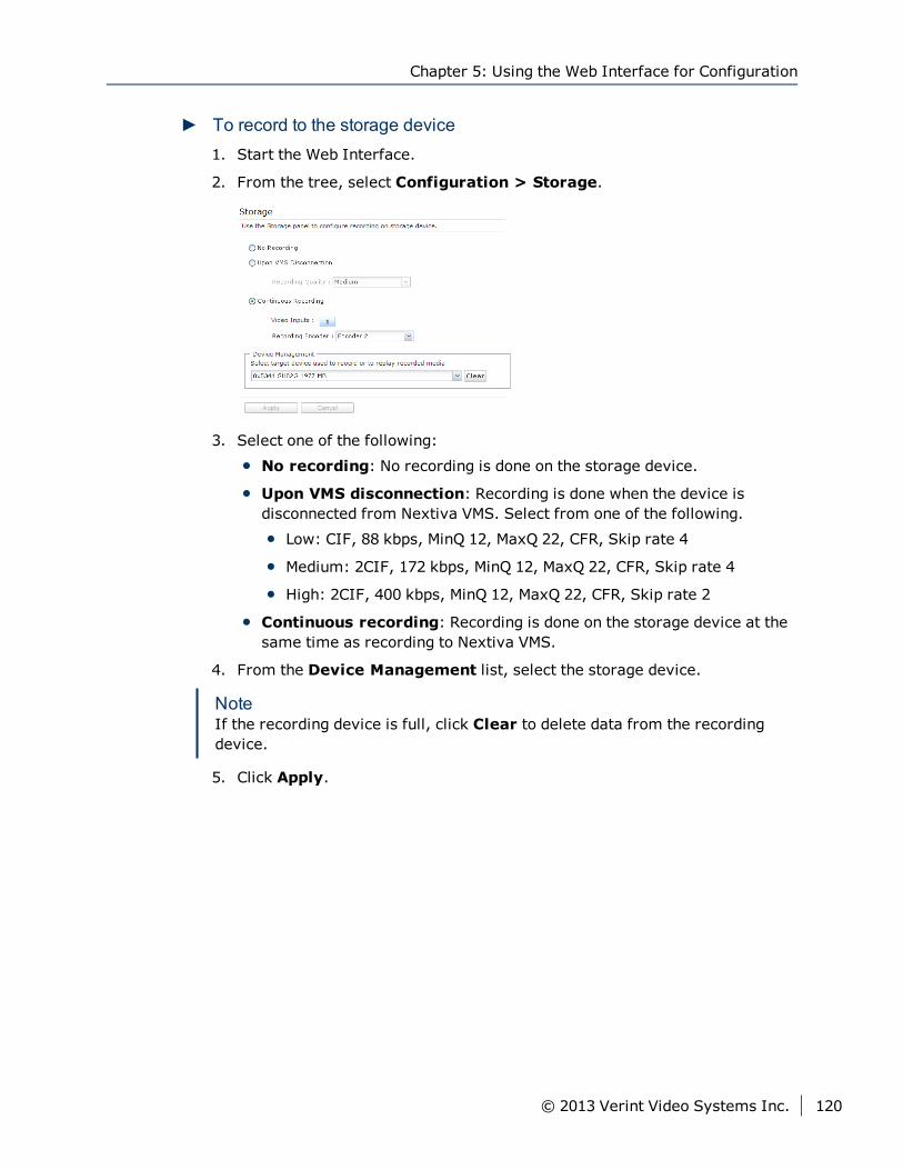
► To record to the storage device1. Start the Web Interface.
2. From the tree, select Configuration > Storage.
3. Select one of the following:
No recording: No recording is done on the storage device.
Upon VMS disconnection: Recording is done when the device isdisconnected from Nextiva VMS. Select from one of the following.
Low: CIF, 88 kbps, MinQ 12, MaxQ 22, CFR, Skip rate 4
Medium: 2CIF, 172 kbps, MinQ 12, MaxQ 22, CFR, Skip rate 4
High: 2CIF, 400 kbps, MinQ 12, MaxQ 22, CFR, Skip rate 2
Continuous recording: Recording is done on the storage device at thesame time as recording to Nextiva VMS.
4. From the Device Management list, select the storage device.
NoteIf the recording device is full, click Clear to delete data from the recordingdevice.
5. Click Apply.
Chapter 5: Using the Web Interface for Configuration
© 2013 Verint Video Systems Inc. 120
This chapter discusses how to perform maintenance and troubleshooting taskson the S1800e series devices using SConfigurator or the Web Interface.Additional troubleshooting task can be performed using a video managementsoftware such Nextiva Video Management Software.
The following topics are discussed:
Firmware Upgrade 122
Device Reboot 124
Factory Default Settings 125
Troubleshooting 126
Chapter 6Chapter 6: Maintaining and
Troubleshooting the Device
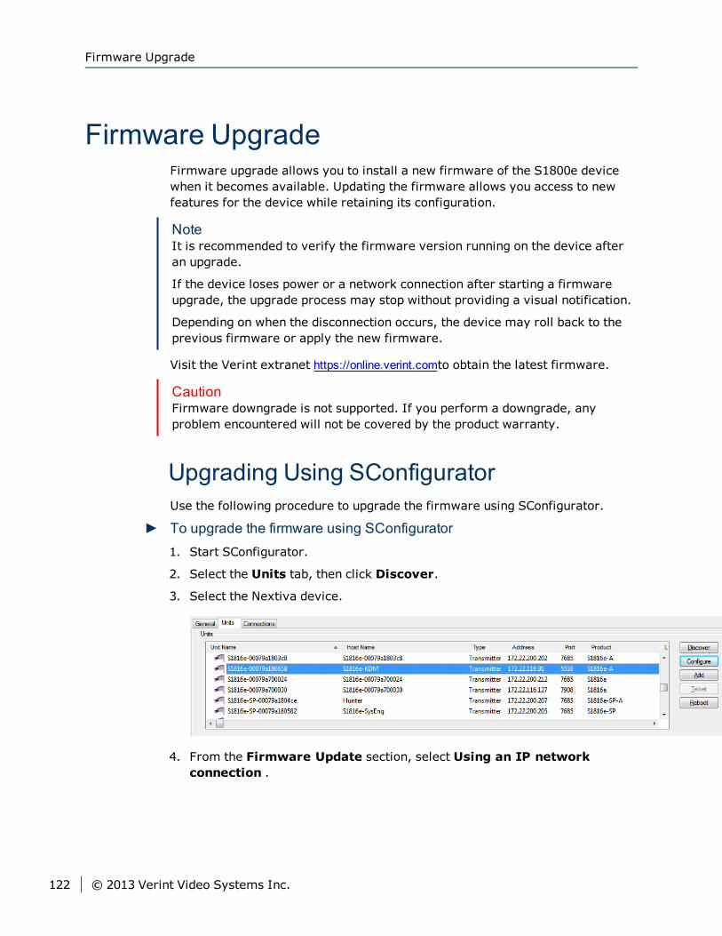
Firmware UpgradeFirmware upgrade allows you to install a new firmware of the S1800e devicewhen it becomes available. Updating the firmware allows you access to newfeatures for the device while retaining its configuration.
NoteIt is recommended to verify the firmware version running on the device afteran upgrade.
If the device loses power or a network connection after starting a firmwareupgrade, the upgrade process may stop without providing a visual notification.
Depending on when the disconnection occurs, the device may roll back to theprevious firmware or apply the new firmware.
Visit the Verint extranet https://online.verint.comto obtain the latest firmware.
CautionFirmware downgrade is not supported. If you perform a downgrade, anyproblem encountered will not be covered by the product warranty.
Upgrading Using SConfiguratorUse the following procedure to upgrade the firmware using SConfigurator.
► To upgrade the firmware using SConfigurator1. Start SConfigurator.
2. Select the Units tab, then click Discover.
3. Select the Nextiva device.
4. From the Firmware Update section, select Using an IP networkconnection .
Firmware Upgrade
122 © 2013 Verint Video Systems Inc.
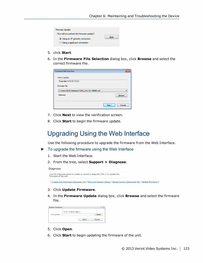
5. click Start.
6. In the Firmware File Selection dialog box, click Browse and select thecorrect firmware file.
7. Click Next to view the verification screen.
8. Click Start to begin the firmware update.
Upgrading Using the Web InterfaceUse the following procedure to upgrade the firmware from the Web Interface.
► To upgrade the firmware using the Web Interface1. Start the Web Interface.
2. From the tree, select Support > Diagnose.
3. Click Update Firmware.
4. In the Firmware Update dialog box, click Browse and select the firmwarefile.
5. Click Open.
6. Click Start to begin updating the firmware of the unit.
Chapter 6: Maintaining and Troubleshooting the Device
© 2013 Verint Video Systems Inc. 123
Performing a Batch Firmware UpdateWith the Nextiva video management software, you can easily update thefirmware for multiple devices in the environment at the same time rather thanupdating them individually. For more information, refer to the Nextivadocumentation.
Device RebootIf the S1800e device does not function the way it should, you can reboot thedevice to re-initialize the settings. To reboot the device using a videomanagement software, refer to the user guide for instructions.
Rebooting the Device Using SConfiguratorUse the following procedure to reboot the device using SConfigurator.
► To reboot using SConfigurator1. Start SConfigurator.
2. Select the Units tab, then click Discover.
3. Select the device, and click Reboot.
4. Click OK.
Rebooting the Edge DeviceRebooting the devices allows you to re-initialize the settings or apply the newparameters. If you change a parameter that requires a reboot and decline toreboot the Edge device immediately, the icon will flash red until the Edgedevice is rebooted. To reboot the device using a video management software,refer to the user guide for instructions.
► To reboot using the Web Interface1. Start the Web Interface.
2. From the Quick Launch bar, click .
Rebooting the Device from the Front PanelUse the following procedure to reboot the device from the front panel.
Performing a Batch Firmware Update
124 © 2013 Verint Video Systems Inc.
► To reboot from the front panel1. On device, press Reset.
Factory Default SettingsIf after rebooting the device still does not function the way it should, you canload the factory default configuration. This operation will restore the factorydefault settings to the device and delete all user-defined values.
Restoring the Factory Default Settings UsingSConfiguratorUse the following procedure to restore the factory default settings usingSConfigurator.
► To restore the factory default settings using SConfigurator1. Start SConfigurator.
2. Select the Units tab, then click Discover.
3. Select the device, and click Configure.
4. Click Load Default Settings.
5. Click OK.
Restoring the Factory Default Settings Usingthe Web InterfaceIf after rebooting the device still does not function the way it should, you canload the factory default configuration. This operation will restore the factorydefault settings to the device and delete all user-defined values.
Chapter 6: Maintaining and Troubleshooting the Device
© 2013 Verint Video Systems Inc. 125
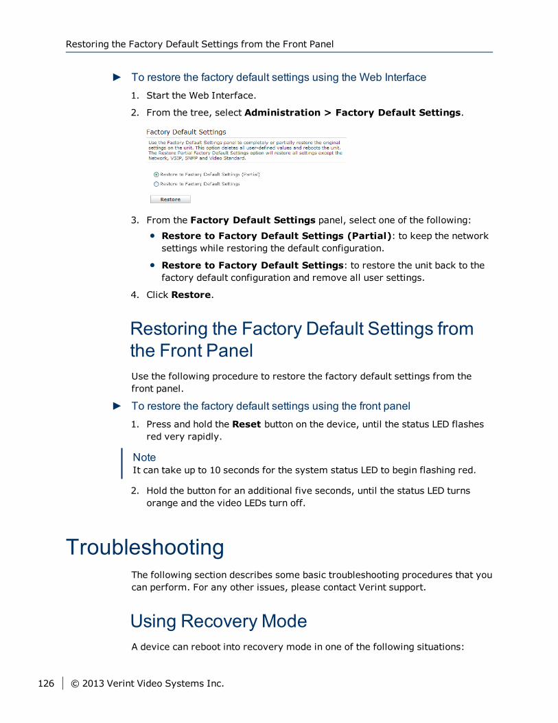
► To restore the factory default settings using the Web Interface1. Start the Web Interface.
2. From the tree, select Administration > Factory Default Settings.
3. From the Factory Default Settings panel, select one of the following:
Restore to Factory Default Settings (Partial): to keep the networksettings while restoring the default configuration.
Restore to Factory Default Settings: to restore the unit back to thefactory default configuration and remove all user settings.
4. Click Restore.
Restoring the Factory Default Settings fromthe Front PanelUse the following procedure to restore the factory default settings from thefront panel.
► To restore the factory default settings using the front panel1. Press and hold the Reset button on the device, until the status LED flashes
red very rapidly.
NoteIt can take up to 10 seconds for the system status LED to begin flashing red.
2. Hold the button for an additional five seconds, until the status LED turnsorange and the video LEDs turn off.
TroubleshootingThe following section describes some basic troubleshooting procedures that youcan perform. For any other issues, please contact Verint support.
Using Recovery ModeA device can reboot into recovery mode in one of the following situations:
Restoring the Factory Default Settings from the Front Panel
126 © 2013 Verint Video Systems Inc.
The device failed to boot normally
The power or network connection to the device is lost during a firmwareupgrade
A flashing orange (1 sec. intervals) or flashing orange (3 blinks at 1 secintervals) and 2 quick red pulses (0.5 sec interval) indicates the device failed toboot normally and has entered recovery mode.
When the device is in recovery mode, the only way you can access the device isusing SConfigurator or the Web Interface with reduced functionality.
NoteSConfigurator
If you are going to use SConfigurator to update the firmware of an device inrecovery mode, you need to know the IP address of the device in order toaccess it.
Web Interface
The Web Interface with reduced functionality is only accessible using theunsecured Hypertext Transfer Protocol (HTTP).
A flashing orange (1 sec. intervals) indicates that the device is using a static IPaddress. A flashing orange (3 blinks at 1 sec intervals) and 2 quick red pulses(0.5 sec interval) indicates that the device is using the APIPA address format.
Once you have access to an device in recovery mode, the only to exit recoverymode if to update the firmware using a valid firmware file.
Performing a Hardware ResetDepending on the severity of the situation, you can reboot the device, load itsdefault configuration, or perform both these actions if the device does notfunction the way is should. You should first start by rebooting the device to seeif this restores functionality back to the device. If the device still does notfunction normally, restore the default configuration.
Losing Connection to a CameraIf the connection to a camera is lost while streaming video to a videomanagement software, the streaming video will display a red/blue frame. Onthe device, a steady red on any of the video status LEDs indicates that aconnection to a camera is lost.
Perform the following tasks:
Chapter 6: Maintaining and Troubleshooting the Device
© 2013 Verint Video Systems Inc. 127
Check the connection between the device and the camera
Check the camera to ensure that it is transmitting video or that it isfunctioning correctly
Check the device to ensure that it is functioning correctly (The system statusLED provides a visual indication on the current state of the device.
Look at the event log
Download a diagnostic file for Verint Technical Support.
SConfigurator cannot find the DeviceSymptom: SConfigurator does not see the device on the Common Port orSConfigurator does not discover a device
Action:
1. Verify that you are running the latest version of SConfigurator.
2. Start SConfigurator.
3. In the General tab, click Program Options.
4. Select the IP address of the correct LAN interface from the IP Address ofthe PC list.
5. Click Common to set the VSIP port to 9541.
6. Ensure that the Discovery IP Address is 255.255.255.255; otherwise,click Reset to Broadcast.
7. Click OK.
8. Click the Units tab.
9. Click Discover.
If the unit still cannot be discovered, try the following:
Verify if the LEDs are flashing. If they are all OFF or at least one of them isnot flashing, verify the network connectivity.
If you know the IP address, try to ping it.
Use install the firmware using SConfigurator or using the Web Interface.
Perform a hard reset and wait a few minutes before trying to discover it. Itwill be configured with its APIPA address (if there is no DHCP server) or anew IP address (if there is a DHCP server).
Quality of the Video is BadSymptom: The video quality from the device is bad
Action:
SConfigurator cannot find the Device
128 © 2013 Verint Video Systems Inc.
Verify the cable between the camera and the device. Try another cable tosee if video quality improves.
Web status should be checked for lock / unlock status
From the Web Interface video tab, verify the values for resolution, bit rateand frame rate are supported by the camera.
If available, try another camera to see if video quality improves.
Ping the device to check for network latency.
From the Web Interface, go to the Clip Retrieval page and verify if thequality of the video.Try the same from other workstations on other locationswithin the same network.
Check the internal temperature of the device from the Home on the webinterface to see if the device is overheating.
Chapter 6: Maintaining and Troubleshooting the Device
© 2013 Verint Video Systems Inc. 129
Appendix AChapter A: Specification and Configuration
Technical Specification 131
Factory Default Configuration 137
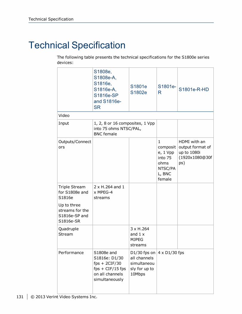
Technical SpecificationThe following table presents the technical specifications for the S1800e seriesdevices:
S1808e,S1808e-A,S1816e,S1816e-A,S1816e-SPand S1816e-SR
S1801eS1802e
S1801e-R S1801e-R-HD
Video
Input 1, 2, 8 or 16 composites, 1 Vppinto 75 ohms NTSC/PAL,BNC female
Outputs/Connectors
1composite, 1 Vppinto 75ohmsNTSC/PAL, BNCfemale
HDMI with anoutput format ofup to 1080i(1920x1080@30fps)
Triple Streamfor S1808e andS1816e
Up to threestreams for theS1816e-SP andS1816e-SR
2 x H.264 and 1x MPEG-4streams
QuadrupleStream
3 x H.264and 1 xMJPEGstreams
Performance S1808e andS1816e: D1/30fps + 2CIF/30fps + CIF/15 fpson all channelssimultaneously
D1/30 fps onall channelssimultaneously for up to10Mbps
4 x D1/30 fps
Technical Specification
131 © 2013 Verint Video Systems Inc.
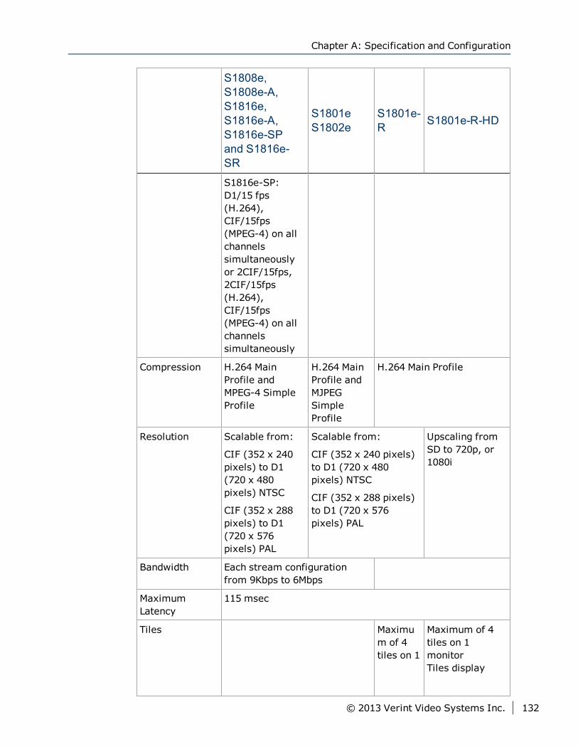
S1808e,S1808e-A,S1816e,S1816e-A,S1816e-SPand S1816e-SR
S1801eS1802e
S1801e-R S1801e-R-HD
S1816e-SP:D1/15 fps(H.264),CIF/15fps(MPEG-4) on allchannelssimultaneouslyor 2CIF/15fps,2CIF/15fps(H.264),CIF/15fps(MPEG-4) on allchannelssimultaneously
Compression H.264 MainProfile andMPEG-4 SimpleProfile
H.264 MainProfile andMJPEGSimpleProfile
H.264 Main Profile
Resolution Scalable from:
CIF (352 x 240pixels) to D1(720 x 480pixels) NTSC
CIF (352 x 288pixels) to D1(720 x 576pixels) PAL
Scalable from:
CIF (352 x 240 pixels)to D1 (720 x 480pixels) NTSC
CIF (352 x 288 pixels)to D1 (720 x 576pixels) PAL
Upscaling fromSD to 720p, or1080i
Bandwidth Each stream configurationfrom 9Kbps to 6Mbps
MaximumLatency
115 msec
Tiles Maximum of 4tiles on 1
Maximum of 4tiles on 1monitorTiles display
Chapter A: Specification and Configuration
© 2013 Verint Video Systems Inc. 132
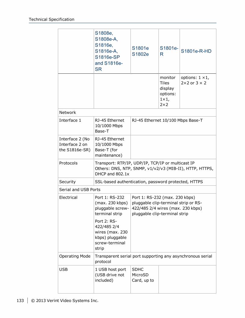
S1808e,S1808e-A,S1816e,S1816e-A,S1816e-SPand S1816e-SR
S1801eS1802e
S1801e-R S1801e-R-HD
monitorTilesdisplayoptions:1×1,2×2
options: 1 ×1,2×2 or 3 × 2
Network
Interface 1 RJ-45 Ethernet10/1000 MbpsBase-T
RJ-45 Ethernet 10/100 Mbps Base-T
Interface 2 (NoInterface 2 onthe S1816e-SR)
RJ-45 Ethernet10/1000 MbpsBase-T (formaintenance)
Protocols Transport: RTP/IP, UDP/IP, TCP/IP or multicast IPOthers: DNS, NTP, SNMP, v1/v2/v3 (MIB-II), HTTP, HTTPS,DHCP and 802.1x
Security SSL-based authentication, password protected, HTTPS
Serial and USB Ports
Electrical Port 1: RS-232(max. 230 kbps)pluggable screw-terminal strip
Port 2: RS-422/485 2/4wires (max. 230kbps) pluggablescrew-terminalstrip
Port 1: RS-232 (max. 230 kbps)pluggable clip-terminal strip or RS-422/485 2/4 wires (max. 230 kbps)pluggable clip-terminal strip
Operating Mode Transparent serial port supporting any asynchronous serialprotocol
USB 1 USB host port(USB drive notincluded)
SDHCMicroSDCard, up to
Technical Specification
133 © 2013 Verint Video Systems Inc.
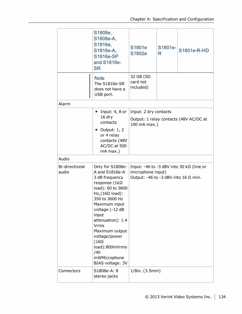
S1808e,S1808e-A,S1816e,S1816e-A,S1816e-SPand S1816e-SR
S1801eS1802e
S1801e-R S1801e-R-HD
NoteThe S1816e-SRdoes not have aUSB port.
32 GB (SDcard notincluded)
Alarm
Input: 4, 8 or16 drycontacts
Output: 1, 2or 4 relaycontacts (48VAC/DC at 500mA max.)
Input: 2 dry contacts
Output: 1 relay contacts (48V AC/DC at100 mA max.)
Audio
Bi-directionalaudio
Only for S1808e-A and S1816e-A3 dB frequencyresponse (1kΩload): 60 to 3600Hz,(16Ω load):350 to 3600 HzMaximum inputvoltage (-12 dBinputattenuation): 1.4VrmsMaximum outputvoltage/power(16Ωload):800mVrms/40mWMicrophoneBIAS voltage: 3V
Input: -46 to -3 dBV into 30 kΩ (line ormicrophone input)Output: -46 to -3 dBV into 16 Ω min.
Connectors S1808e-A: 8stereo jacks
1/8in. (3.5mm)
Chapter A: Specification and Configuration
© 2013 Verint Video Systems Inc. 134
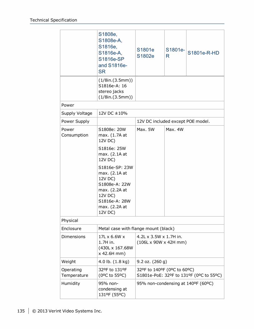
S1808e,S1808e-A,S1816e,S1816e-A,S1816e-SPand S1816e-SR
S1801eS1802e
S1801e-R S1801e-R-HD
(1/8in.(3.5mm))S1816e-A: 16stereo jacks(1/8in.(3.5mm))
Power
Supply Voltage 12V DC ±10%
Power Supply 12V DC included except POE model.
PowerConsumption
S1808e: 20Wmax. (1.7A at12V DC)
S1816e: 25Wmax. (2.1A at12V DC)
S1816e-SP: 23Wmax. (2.1A at12V DC)S1808e-A: 22Wmax. (2.2A at12V DC)S1816e-A: 28Wmax. (2.2A at12V DC)
Max. 5W Max. 4W
Physical
Enclosure Metal case with flange mount (black)
Dimensions 17L x 6.6W x1.7H in.(430L x 167.68Wx 42.6H mm)
4.2L x 3.5W x 1.7H in.(106L x 90W x 42H mm)
Weight 4.0 lb. (1.8 kg) 9.2 oz. (260 g)
OperatingTemperature
32ºF to 131ºF(0ºC to 55ºC)
32ºF to 140ºF (0ºC to 60ºC)S1801e-PoE: 32ºF to 131ºF (0ºC to 55ºC)
Humidity 95% non-condensing at131ºF (55ºC)
95% non-condensing at 140ºF (60ºC)
Technical Specification
135 © 2013 Verint Video Systems Inc.
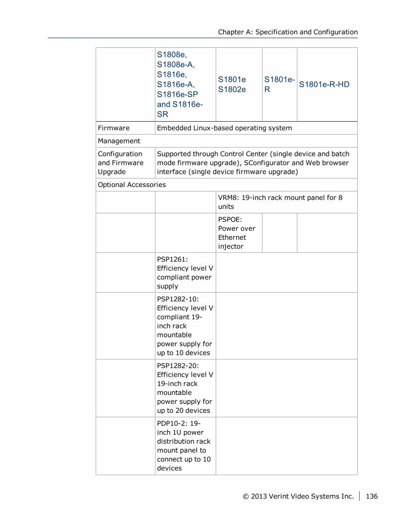
S1808e,S1808e-A,S1816e,S1816e-A,S1816e-SPand S1816e-SR
S1801eS1802e
S1801e-R S1801e-R-HD
Firmware Embedded Linux-based operating system
Management
Configurationand FirmwareUpgrade
Supported through Control Center (single device and batchmode firmware upgrade), SConfigurator and Web browserinterface (single device firmware upgrade)
Optional Accessories
VRM8: 19-inch rack mount panel for 8units
PSPOE:Power overEthernetinjector
PSP1261:Efficiency level Vcompliant powersupply
PSP1282-10:Efficiency level Vcompliant 19-inch rackmountablepower supply forup to 10 devices
PSP1282-20:Efficiency level V19-inch rackmountablepower supply forup to 20 devices
PDP10-2: 19-inch 1U powerdistribution rackmount panel toconnect up to 10devices
Chapter A: Specification and Configuration
© 2013 Verint Video Systems Inc. 136
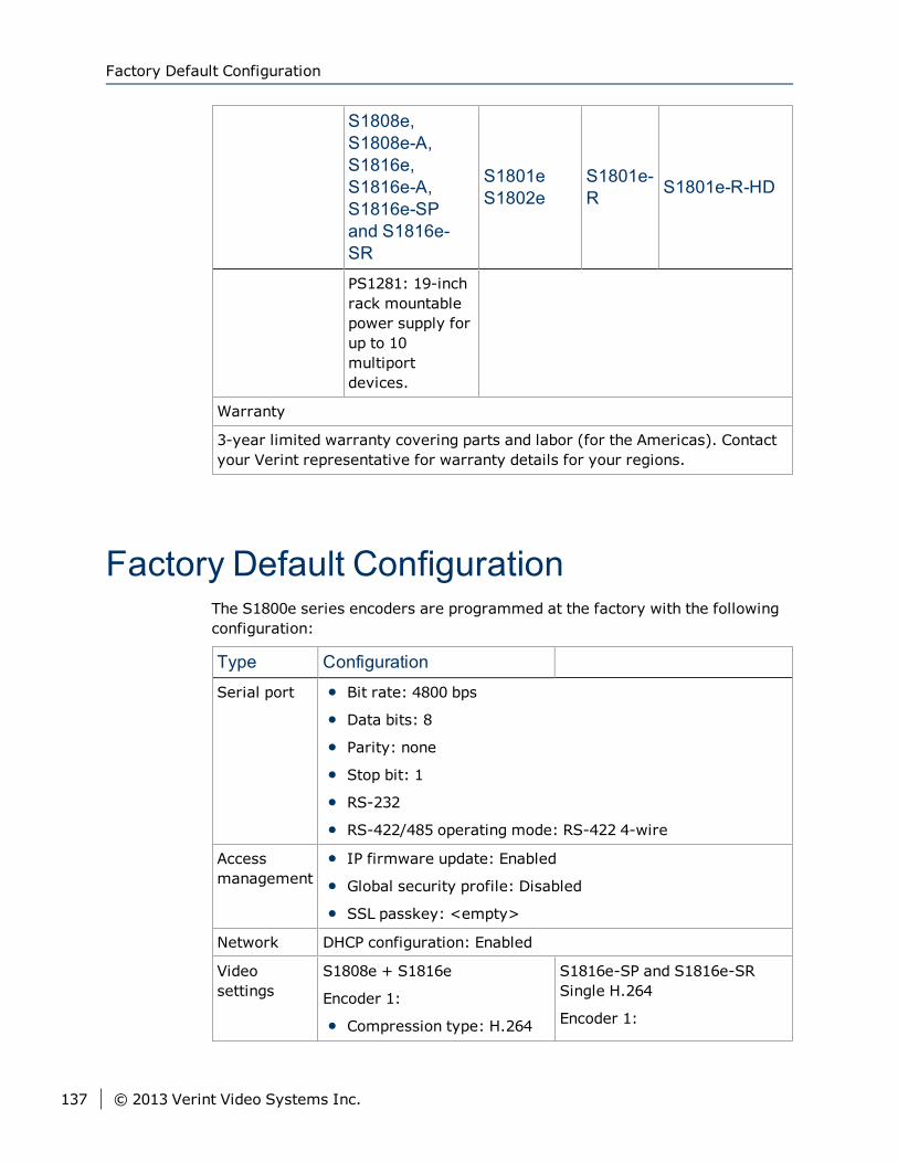
S1808e,S1808e-A,S1816e,S1816e-A,S1816e-SPand S1816e-SR
S1801eS1802e
S1801e-R S1801e-R-HD
PS1281: 19-inchrack mountablepower supply forup to 10multiportdevices.
Warranty
3-year limited warranty covering parts and labor (for the Americas). Contactyour Verint representative for warranty details for your regions.
Factory Default ConfigurationThe S1800e series encoders are programmed at the factory with the followingconfiguration:
Type Configuration
Serial port Bit rate: 4800 bps
Data bits: 8
Parity: none
Stop bit: 1
RS-232
RS-422/485 operating mode: RS-422 4-wire
Accessmanagement
IP firmware update: Enabled
Global security profile: Disabled
SSL passkey: <empty>
Network DHCP configuration: Enabled
Videosettings
S1808e + S1816e
Encoder 1:
Compression type: H.264
S1816e-SP and S1816e-SRSingle H.264
Encoder 1:
Factory Default Configuration
137 © 2013 Verint Video Systems Inc.
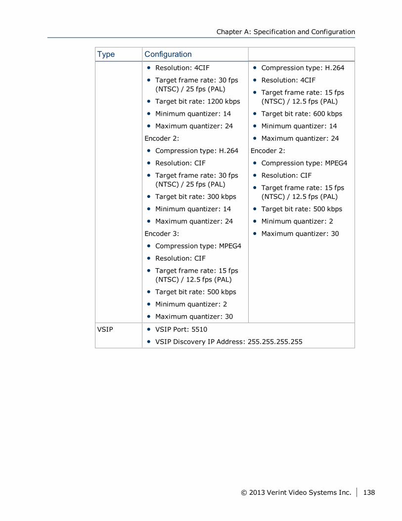
Type Configuration
Resolution: 4CIF
Target frame rate: 30 fps(NTSC) / 25 fps (PAL)
Target bit rate: 1200 kbps
Minimum quantizer: 14
Maximum quantizer: 24
Encoder 2:
Compression type: H.264
Resolution: CIF
Target frame rate: 30 fps(NTSC) / 25 fps (PAL)
Target bit rate: 300 kbps
Minimum quantizer: 14
Maximum quantizer: 24
Encoder 3:
Compression type: MPEG4
Resolution: CIF
Target frame rate: 15 fps(NTSC) / 12.5 fps (PAL)
Target bit rate: 500 kbps
Minimum quantizer: 2
Maximum quantizer: 30
Compression type: H.264
Resolution: 4CIF
Target frame rate: 15 fps(NTSC) / 12.5 fps (PAL)
Target bit rate: 600 kbps
Minimum quantizer: 14
Maximum quantizer: 24
Encoder 2:
Compression type: MPEG4
Resolution: CIF
Target frame rate: 15 fps(NTSC) / 12.5 fps (PAL)
Target bit rate: 500 kbps
Minimum quantizer: 2
Maximum quantizer: 30
VSIP VSIP Port: 5510
VSIP Discovery IP Address: 255.255.255.255
Chapter A: Specification and Configuration
© 2013 Verint Video Systems Inc. 138
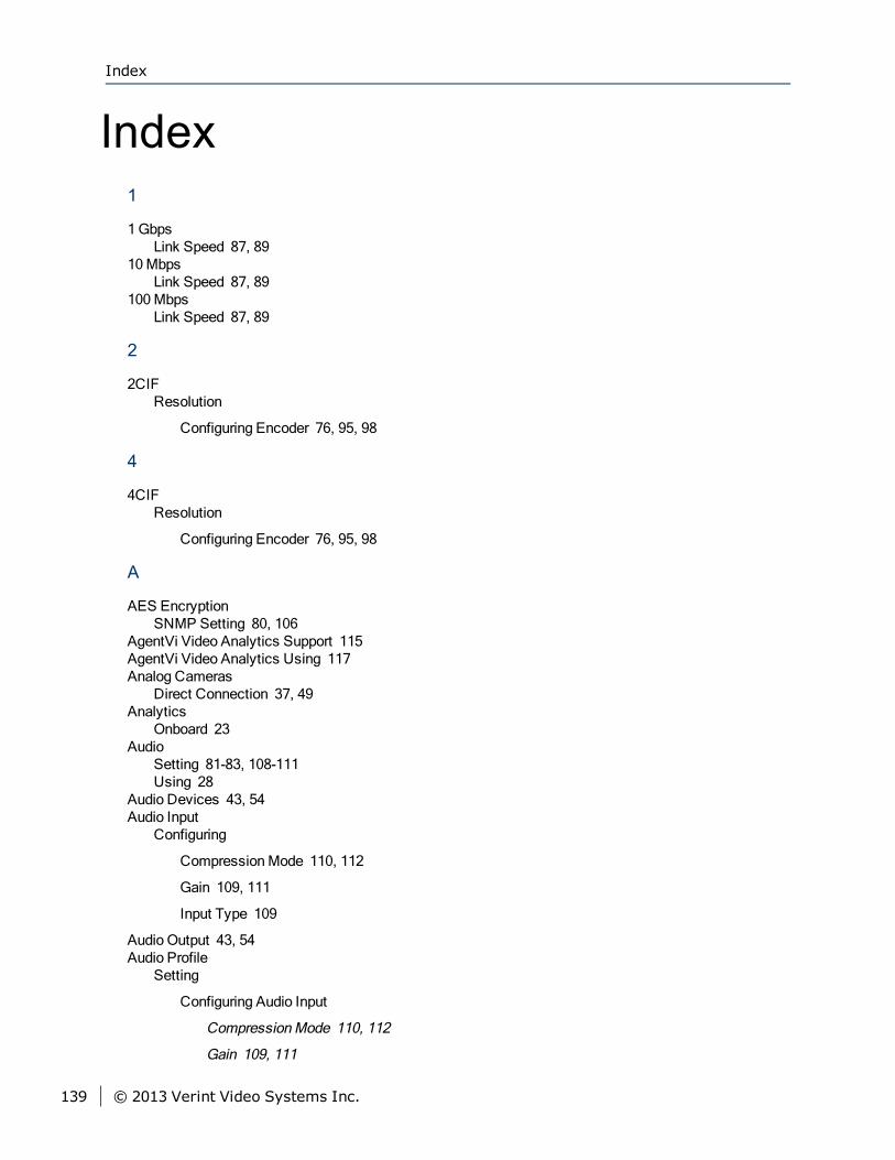
Index1
1GbpsLink Speed 87, 89
10MbpsLink Speed 87, 89
100MbpsLink Speed 87, 89
2
2CIFResolution
Configuring Encoder 76, 95, 98
4
4CIFResolution
Configuring Encoder 76, 95, 98
A
AES EncryptionSNMP Setting 80, 106
AgentVi Video Analytics Support 115AgentVi Video Analytics Using 117Analog Cameras
Direct Connection 37, 49Analytics
Onboard 23Audio
Setting 81-83, 108-111Using 28
Audio Devices 43, 54Audio Input
Configuring
CompressionMode 110, 112
Gain 109, 111
Input Type 109
Audio Output 43, 54Audio Profile
Setting
Configuring Audio Input
CompressionMode 110, 112
Gain 109, 111
Index
139 © 2013 Verint Video Systems Inc.
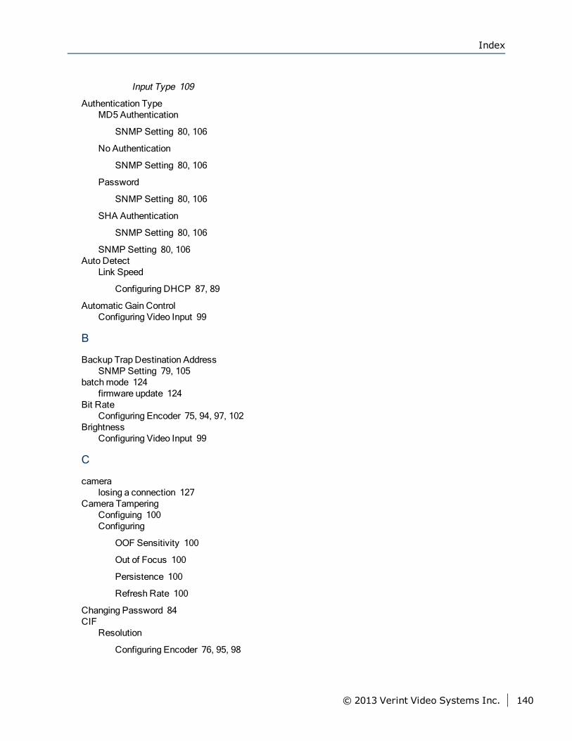
Input Type 109
Authentication TypeMD5 Authentication
SNMP Setting 80, 106
No Authentication
SNMP Setting 80, 106
Password
SNMP Setting 80, 106
SHA Authentication
SNMP Setting 80, 106
SNMP Setting 80, 106Auto Detect
Link Speed
Configuring DHCP 87, 89
Automatic Gain ControlConfiguring Video Input 99
B
Backup Trap Destination AddressSNMP Setting 79, 105
batchmode 124firmware update 124
Bit RateConfiguring Encoder 75, 94, 97, 102
BrightnessConfiguring Video Input 99
C
cameralosing a connection 127
Camera TamperingConfiguing 100Configuring
OOF Sensitivity 100
Out of Focus 100
Persistence 100
Refresh Rate 100
Changing Password 84CIF
Resolution
Configuring Encoder 76, 95, 98
Index
© 2013 Verint Video Systems Inc. 140
Community NameSNMP Setting 80, 105
CompressionModeConfiguring Audio Input 110, 112Configuring Encoder 76, 95, 98
configurationdefault 127, 137
Configuring Audio InputCompressionMode 110, 112Gain 109, 111Input Type 109
Configuring Camera Tampering 100OOF Sensitivity 100Out of Focus 100Persistence 100Refresh Rate 100
Configuring Decoder 102Configuring DHCP
Default Gateway 86, 88Ethernet Adapter 87, 89Hostname 86, 88Link Speed 87, 89
1Gbps full duplex 87, 89
1Gbps half duplex 87, 89
10Mbps full duplex 87, 89
10Mbps half duplex 87, 89
100Mbps full duplex 87, 89
100Mbps half duplex 87, 89
Auto Detect 87, 89
Configuring EncoderBit Rate 75, 94, 97, 102CompressionMode 76, 95, 98FrameRate 75, 94, 97
NTSC 75, 94, 97
PAL 75, 94, 97
I-Frame 76, 95, 98Intra Interval 76, 95, 98Quantizer 75, 95, 97Rate Control Mode 76, 95, 98
Constant Bit Rate 76, 95, 98
Constant FrameRate 76, 95, 98
Resolution 76, 95, 98
2CIF 76, 95, 98
4CIF 76, 95, 98
Index
141 © 2013 Verint Video Systems Inc.
CIF 76, 95, 98
D1 76, 95, 98
Configuring IP Address 59, 85ConfiguringMotion Detection 101
Lower Thresh 102Mask 101Mask State 101Nb Frames 102Upper Thresh 101Vector Length 102
Configuring S1816e-SP Encoder 70Configuring Video Input
AGC 99Brightness 99Contrast 99Hue 99Saturation 99
Configuring VideoOutput 103Discovery Mode 103Dwell Time 104Receiver Mode 104
connectionRS-232 39, 51to a camera, losing[connection
camera, losing] 127
Constant Bit RateRate Control Mode
Configuring Encoder 76, 95, 98
Constant FrameRateRate Control Mode
Configuring Encoder 76, 95, 98
ContrastConfiguring Video Input 99Configuring VideoOutput 104
Creating Video Analytics Rules 23
D
D1Resolution
Configuring Encoder 76, 95, 98
DecoderConfiguring 102
default configuration 127, 137Default Gateway 86, 88
Configuring DHCP 86, 88default password 84
Index
© 2013 Verint Video Systems Inc. 142
default username 84DES Encryption
SNMP Setting 80, 106Device Discovery 58Devices
Dual-Port 17Multi-Port 19-20, 22Single-Port 17
DHCPConfiguring
Default Gateway 86, 88
Ethernet Adapter 87, 89
Hostname 86, 88
Link Speed 87, 89
1Gbps full duplex 87, 89
1Gbps half duplex 87, 89
10Mbps full duplex 87, 89
10Mbps half duplex 87, 89
100Mbps full duplex 87, 89
100Mbps half duplex 87, 89
Auto Detect 87, 89
Discovery Mode 58Configuring VideoOutput 103
DowngradeOf Firmware 122Dual-Port Devices 17Duplex Mode
Full 87, 89Half 87, 89
E
Enabling Nextiva Analytics 112Encoder
Configuring
Bit Rate 75, 94, 97, 102
CompressionMode 76, 95, 98
FrameRate 75, 94, 97
NTSC 75, 94, 97
PAL 75, 94, 97
I-Frame 76, 95, 98
Intra Interval 76, 95, 98
Quantizer 75, 95, 97
Index
143 © 2013 Verint Video Systems Inc.
Rate Control Mode 76, 95, 98
Constant Bit Rate 76, 95, 98
Constant FrameRate 76, 95, 98
Resolution 76, 95, 98
2CIF 76, 95, 98
4CIF 76, 95, 98
CIF 76, 95, 98
D1 76, 95, 98
equipment list 33, 46Ethernet Adapter 87, 89
Configuring DHCP 87, 89
F
factory default configuration 127, 137Firmware
Downgrading 122firmware update 122-124, 126Flat Surface
Installing 33, 46FrameRate
Configuring Encoder 75, 94, 97
NTSC 75, 94, 97
PAL 75, 94, 97
FullDuplex Mode 87, 89
G
GainConfiguring Audio Input 109, 111
H
HalfDuplex Mode 87, 89
hardware reset 127Hostname 86, 88
Configuring DHCP 86, 88Hue
Configuring Video Input 99
I
I-FrameConfiguring Encoder 76, 95, 98
I/O, alarm or audio 31
Index
© 2013 Verint Video Systems Inc. 144
InputAudio 43, 54
Input TypeConfiguring Audio Input 109
Installing Flat Surface 33, 46Installing Rack 33, 47Intra Interval
Configuring Encoder 76, 95, 98IP Address
Backup Trap Destination
SNMP Setting 79, 105
Primary Trap Destination
SNMP Setting 79, 105
IP Address Configuration 59, 85
L
LED, status 28Link Speed 87, 89
1Gbps full duplex 87, 891Gbps half duplex 87, 8910Mbps full duplex 87, 8910Mbps half duplex 87, 89100Mbps full duplex 87, 89100Mbps half duplex 87, 89Auto Detect 87, 89Configuring DHCP 87, 89
1Gbps full duplex 87, 89
1Gbps half duplex 87, 89
10Mbps full duplex 87, 89
10Mbps half duplex 87, 89
100Mbps full duplex 87, 89
100Mbps half duplex 87, 89
Auto Detect 87, 89
loading default configuration 127, 137losing a connection to a camera 127Lower Thresh
ConfiguringMotion Detection 102
M
maintenance 121Mask
ConfiguringMotion Detection 101Mask State
ConfiguringMotion Detection 101
Index
145 © 2013 Verint Video Systems Inc.
ModeCompression
Configuring Encoder 76, 95, 98
Motion DetectionConfiguing 101Configuring
Lower Thresh 102
Mask 101
Mask State 101
Nb Frames 102
Upper Thresh 101
Vector Length 102
Multi-Port Devices 19-20, 22
N
Nb FramesConfiguringMotion Detection 102
Network Cable Connection 38, 50Network Configuration
Setting
DHCP 86-89
Nextiva Analytics 23Enabling 112Using 114
NTSCConfiguring FrameRate 75, 94, 97Setting Video Standard 73, 93
O
On-Screen DisplaySetting 118
Onboard Analytics 23OOF Sensitivity
Configuring Camera Tampering 100options, when ordering a device 33, 46Out of Focus
Configuring Camera Tampering 100Output
Audio 43, 54
P
PALConfiguring FrameRate 75, 94, 97Setting Video Standard 73, 93
Index
© 2013 Verint Video Systems Inc. 146
passwordChanging 84default 84
PersistenceConfiguring Camera Tampering 100
pinoutserial port 39, 50
Primary Trap Destination AddressSNMP Setting 79, 105
Privacy PasswordSNMP Setting 80, 106
Privacy ProtocolAES Encryption
SNMP Setting 80, 106
DES Encryption
SNMP Setting 80, 106
No Encryption
SNMP Setting 80, 106
SNMP Setting 80, 106protocols supported, serial 39, 50
Q
QuantizerConfiguring Encoder 75, 95, 97
R
RackInstalling 33, 47
Rate Control ModeConfiguring Encoder 76, 95, 98
Constant Bit Rate 76, 95, 98
Constant FrameRate 76, 95, 98
Receiver ModeConfiguring VideoOutput 104
Recording to Storage Card 119recovery mode 126
firmware update 126red/blue display 127Refresh Rate
Configuring Camera Tampering 100Reset button 126reset to factory default 127, 137Resolution
Configuring Encoder 76, 95, 98
2CIF 76, 95, 98
4CIF 76, 95, 98
Index
147 © 2013 Verint Video Systems Inc.
CIF 76, 95, 98
D1 76, 95, 98
resolution, video 24, 27Rules
Creating Video Analytics 23
S
S1816e-SP EncoderConfiguring 70
SaturationConfiguring Video Input 99
serial port 39, 50serial protocols supported 39, 50Setting
Audio 81-83, 108-111Audio Profile
Configuring Audio Input
CompressionMode 110, 112
Gain 109, 111
Input Type 109
Network Configuration
DHCP
Default Gateway 86, 88
Ethernet Adapter 87, 89
Hostname 86, 88
Link Speed 87, 89
1Gbps full duplex 87, 89
1Gbps half duplex 87, 89
10Mbps full duplex 87, 89
10Mbps half duplex 87, 89
100Mbps full duplex 87, 89
100Mbps half duplex 87, 89
Auto Detect 87, 89
SNMP 78, 104
Authentication Type 80, 106
MD5 Authentication 80, 106
No Authentication 80, 106
Password 80, 106
SHA Authentication 80, 106
Index
© 2013 Verint Video Systems Inc. 148
Backup Trap Destination Address 79, 105
Community Name 80, 105
Primary Trap Destination Address 79, 105
Privacy Password 80, 106
Privacy Protocol 80, 106
AES Encryption 80, 106
DES Encryption 80, 106
No Encryption 80, 106
System Contact 79, 105
System Location 79, 105
User Name 80, 105
Video Profile
Configuring Video Input
AGC 99, 103
Brightness 99
Contrast 99
Hue 99
Saturation 99
Configuring VideoOutput 103
Dwell Time 104
Receiver Mode 104
Video Standard
NTSC 73, 93
PAL 73, 93
Setting DHCPDefault Gateway 86, 88Ethernet Adapter 87, 89Hostname 86, 88Link Speed 87, 89
1Gbps full duplex 87, 89
1Gbps half duplex 87, 89
10Mbps full duplex 87, 89
10Mbps half duplex 87, 89
100Mbps full duplex 87, 89
100Mbps half duplex 87, 89
Auto Detect 87, 89
Setting On-Screen Display 118
Index
149 © 2013 Verint Video Systems Inc.
Setting The Vsip 78, 81-83, 104, 108-111shipment list 33, 46Single-Port Devices 17SNMP
Setting 78, 104
Authentication Type 80, 106
MD5 Authentication 80, 106
No Authentication 80, 106
Password 80, 106
SHA Authentication 80, 106
Backup Trap Destination Address 79, 105
Community Name 80, 105
Primary Trap Destination Address 79, 105
Privacy Password 80, 106
Privacy Protocol 80, 106
AES Encryption 80, 106
DES Encryption 80, 106
No Encryption 80, 106
System Contact 79, 105
System Location 79, 105
User Name 80, 105
Speed1Gbps 87, 8910Mbps 87, 89100Mbps 87, 89
status LED 28Storage Card
Recording 119Support
AgentVi Video Analytics 115System Contact
SNMP Setting 79, 105System Location
SNMP Setting 79, 105system status LED 28
T
troubleshooting 121
U
updating firmware 122-123
Index
© 2013 Verint Video Systems Inc. 150
Upper ThreshConfiguringMotion Detection 101
User NameSNMP Setting 80, 105
usernamedefault 84
UsingAgentVi Video Analytics 117
Using Audio 28Using Nextiva Analytics 114
V
Vector LengthConfiguringMotion Detection 102
Video AnalyticsCreating 23
Video InputConfiguring
AGC 99
Brightness 99
Contrast 99
Hue 99
Saturation 99
VideoOutputConfiguring 103
Discovery Mode 103
Dwell Time 104
Receiver Mode 104
Video ProfileSetting
Configuring Video Input
AGC 99
Brightness 99
Contrast 99
Hue 99
Saturation 99
Configuring VideoOutput 103
Discovery Mode 103
Dwell Time 104
Receiver Mode 104
Index
151 © 2013 Verint Video Systems Inc.
Video StandardSetting
NTSC 73, 93
PAL 73, 93
For more information, please visit us at http://www.verint.com/solutions/video-situation-intelligence/index.html
Americas: [email protected]
EMEA: [email protected]
APAC: [email protected]
All other trademarks and product names are the property of their respective owners.
The information in this document may be superseded by subsequent documents.
Index
© 2013 Verint Video Systems Inc. 152