Next generation VRV system featuring VRT now with Airside ... · 1 2 Daikin’s VRT Smart...
9
PVTVAU1807 Preview Brochure Next generation VRV system featuring VRT now with Airside Control Heat Recovery 50 Hz Heat Pump 50 Hz
Transcript of Next generation VRV system featuring VRT now with Airside ... · 1 2 Daikin’s VRT Smart...
All rights reserved 04/18 AKc
•Speci�cations, designs and other content appearing in this brochure are current as of April 2018 but subject to change without notice.
1. Air conditioners should not be installed in areas where corrosive gases, such as acid gas or alkaline gas, are produced.2. If the outdoor unit is to be installed close to the sea shore, direct exposure to the sea breeze should be avoided. If you need to install the outdoor unit close to the sea shore, contact your local distributor.
Cautions on product corrosion
Ask a quali�ed installer or contractor to install this product. Do not try to install the product yourself. Improper installation can result in water or refrigerant leakage, electrical shock, �re or explosion.
Use only those parts and accessories supplied or speci�ed by Daikin. Ask a quali�ed installer or contractor to install those parts and accessories. Use of unauthorised parts and accessories or improper installation of parts and accessories can result in water or refrigerant leakage, electrical shock, �re or explosion.
Read the user's manual carefully before using this product. The user's manual provides important safety instructions and warnings. Be sure to follow these instructions and warnings.
If you have any enquiries, please contact your local importer, distributor and/or retailer.
PVTVAU1807Preview Brochure
Next generation VRV system featuringVRT now with Airside Control
VRV is a trade mark of Daikin Industries, Ltd.VRV Air Conditioning System is the world's �rst individual air conditioning system with variable refrigerant �ow control and was commercialised by Daikin in 1982.VRV is the trade mark of Daikin Industries, Ltd., which is derived from the technology we call "variable refrigerant volume."
Heat Recovery 50 HzHeat Pump 50 Hz

1 2
Daikin’s VRT Smart technology takes comfort and energy performance to the next level. Building on our variable refrigerant temperature technology which enables the evaporating temperature to adjust to meet the varying load, VRT Smart is now also able to automatically adjust the indoor unit air�ow rate (Airside Control) to ensure optimal comfort and energy performance is delivered at all times.
VRT Smart Control (Ful ly Automatic Energy-saving Refrigerant Control)
•Overview of the control (system control �ow)
Select the target refrigerant temperature
2 Compressor speed control3
Target indoor units1
Coordinated control
The following items are calculated based on the required capacity:
•Changes in the room temperature during low-load operation*
Temperature setting
Start
Turned off by the thermostat
Subject to VRT smart control Subject to VRT control
Advanced technologies for greater energy savings
Different automatic energy-saving refrigerant control applies depending on the indoor units connected.
Software technology
By uniting advanced software and hardware technologies, VRV H Series / R Series is able to attain greater heights in energy savings and comfort.
The smooth control (which keeps the compressor running) saves energy and ensures comfort during low-load operation.
Note:•For the classi�cation of indoor units (VRT smart control and VRT control), refer to pages 3–4.•If a system has indoor units subject to both VRT smart and VRT control, the system is operated under VRT control.•If a system has both outdoor-air processing air conditioners and outdoor-air processing type indoor units, VRT smart control and VRT control are disabled only available during either all cooling operation or all heating operation.
The VRT smart control also controls the air�ow rate of indoor units automatically*, to achieve energy-saving control.
Temperature data received from indoor units
•Indoor fan air volume•Target value of refrigerant
temperature
Conventional air-conditioning methodChanges in the room temperature: LargeThe power consumption attributed to the start-stop loss also increases the load.
Fully automatic energy-saving refrigerant controlChanges in the room temperature: Small Wasted power consumption is also minimised.
Turned off by the thermostat
Turned off by the thermostat
Room temperature
*Graph shown above is for illustration purpose only.
* Air�ow rate should be set to “Auto”.
VRT Smart and VRT control is most effective when all the indoor units operate under low load conditions in a similar manner. Low load conditions is the time when room temperature approaches set temperature. For this reason, please note the following to maximise ef�cacy.
•When selecting indoor unitsIndoor units are installed in a system so that they operate largely under the same conditions.Energy ef�ciency decreases for the installation patterns indicated below.Example:
1) A load imbalance occurs because an indoor unit on the same system is installed near the perimeter of the room or in the vicinity of a room entrance.
2) Different operating hours for indoor units.3) Energy ef�ciency decreases when the set temperature of a speci�ed indoor unit is set to an extreme during cooling
operation. E.g. 18˚C
Optimum utilisation of VRT Smart Control and VRT Control
New
New Single Unit Model
Product lineup6 8 10 12 14 16 18 20 22 24 26 28 30 32 34 36 38 40 42 44 46 48 50 52 54 56 58 60Class
Standard Type
High-COP Type —— — — — — —— — — — — — — —
VRV H SERIES
VRV R SERIES
6 8 10 1210
12
+
8
8
+8
10
+8
12
+6
6
+6
8
+
12
12
+12
14
+12
16
+12
18
+16
16
+16
18
+16
20
+
12
12
+
14
+
6
8
+
8
+
10
12
+
12
+
12
12
+
12
+
8
8
+
8
+
8
8
+
10
+
8
10
+
12
+
8
12
+
12
+
8
8
+
12
+
12
12
+
16
+
10
16
+
16
+
12
16
+
16
+
14
16
+
16
+
16
16
+
16
+
16
16
+
18
+
16
18
+
18
+
18
18
+
18
+
18
18
+
20
+
18
20
+
20
+
20
20
+
20
+14 16 18 20
The VRV Heat Recovery (VRV R) series now features a 6 Class single module model for additional 12, 14 and 22 Class High-COP type combinations.
New Scroll Compressor*
Refrigerant leakage is minimised during low-load operation.Operational loss due to refrigerant leakage is reduced with the inclusion of a proprietary back pressure control mechanism to ensure stable low-load operation.
•Compressor ef�ciency*
Back pressure control mechanism
The orbiting scroll is engaged by the pressure difference between high and low pressures. The force engaging the orbiting scroll decreases during low-load operation, resulting in compression leakage from movable parts.
Conventional mechanism
The pressure on the orbiting scroll is optimised according to operating conditions. As a result, the orbiting scroll has been stabilised to increase ef�ciency during low-load operation.
New intermediate pressure mechanism
The force pressing the orbiting scroll decreases during low-load operation.
The intermediate pressure maintains pressure on the orbiting scroll during low-load operation.
* The new mechanism is only applicable to Heat Pump models in RXYQ10, 12 and 20A models.
Hardware technology
The intermediate pressure (back pressure) optimises the force pressing the movable scroll depending on the operating condition.
Co
mp
ress
or
ef�
cie
nc
y
The back pressure control mechanism increases the ef�ciency during low-load operation.
New compressorConventional compressor
Load factor
New
*Graph shown above is for illustration purpose only.
Intermediate pressure adjustment port

3 4
Indoor unit lineupA mixed combination of VRV indoor units and residential indoor units can be included into one system, opening the door to stylish and quiet indoor units.
VRV indoor units
FXSQ-PAVE
FXDYQ-MAV1
Middle StaticPressure CeilingMounted Duct
Ceiling Concealed Duct
Type Model Name
FXFSQ-AVMCeiling Mounted Cassette(Round Flow with Sensing)
Ceiling Mounted Cassette(Round Flow)
Ceiling Mounted Cassette(Compact Multi Flow)
Ceiling Mounted Cassette(Double Flow)
Ceiling Mounted Cassette(Single Flow)
Slim Ceiling Mounted Duct(Standard Series)
Ceiling Mounted Duct
Ceiling Suspended
Wall Mounted
Floor Standing
ConcealedFloor Standing
4-Way Flow Ceiling Suspended
Outdoor-Air Processing Unit
FXDQ-TV1A(A)Slim CeilingMounted Duct(Compact Series)
FXMQ-MFV1
Heat Reclaim Ventilator
Heat Reclaim Ventilator with DX-Coil and Humidi�er VKM-GA(M)V1
VAM-GJVE
Air�ow rate 500-1000 m3/h
Air�ow rate 150-2000 m3/h
Indoor units subject to VRT smart control
New
New lineup
New
New
New
New
New
FXEQ-AV36
FXFQ-PVE
FXZQ-A2VEB
FXCQ-MVE
FXMQ-PAVE
New FXMQ-PV1A
FXUQ-AVEB
FXHQ-MAVE
FXAQ-PVE
FXLQ-MAVE
FXNQ-MAVE
New
FXDQ-PDVE(with drain pump)
FXDQ-NDVE(with drain pump)
(700mm width type)
(900 / 1,100mm width type)
* For connection of the air handling unit, please contact our sales of�ce.Notes: 1. For indoor units without 'VRT Smart', the standard 'VRT' control is available (excludes Heat Reclaim Ventilators & Outdoor-Air Processing Unit). 2. FXDQ-TV1AA models denote a built-in multi tenancy adaptor. This adaptor allows an independent 24V power source to be supplied to the indoor unit PCB in conjunction with 1 phase power from the tenants board. This ensures critical operations, such as oil return are not affected should there be an interruption to the main indoor unit power.
VRV indoor units only
64Max.
indoorunits
VRV indoor units
BP unit
32Max.
indoorunits
Residential indoor units
BP unit
Residential indoor units only32Max.
indoorunits
BP unit
VRV indoor unit system
Residential indoor unit only system
Mixed residential and VRV indoor unit system
VRV indoor unit type combinations
• If a system has indoor units subject to both VRT smart and VRT control, the system is operated under VRT control.• If a system has both outdoor-air processing air conditioners and outdoor-air processing type indoor units, VRT smart
control and VRT control are disabled.
• BP units are necessary for residential indoor units. Only single outdoor unit (RXYQ6-20A) can be connected.• If a system has both residential indoor units and VRV indoor units, the system is operated under VRT control.
• BP units are necessary for residential indoor units. Only single outdoor unit (RXYQ6-20A) can be connected.• If a system has only residential indoor units, the system is operated under VRT control.
New capacity
Enhanced range of choices
20
0.8
20
25
1
25
32
1.25
31.25
40
1.6
40
50
2
50
63
2.5
62.5
71
3
71
80
3.2
80
100
4
100
125
5
125
140
6
140
145
5.8
145
160
6.4
160
180
7.2
180
200
8
200
250
10
250
Residential indoor units with connection to BP units (VRV H SERIES ONLY)25 35
25 35
2.5 3.5
50 60 71
50 60 71
5.0 6.0 7.1Rated Capacity (kW)Type Model Name
Capacity Index
Slim CeilingMounted Duct
Ceiling Mounted Cassette (Compact Multi Flow)
Wall Mounted
FFQ-BV1B
FDXS-CVMA
CTXG-PVMAW
CTXG-PVMAS
FTXS-KVMA
FTXS-KAVMA
(900/1,100 mm width type)
20
20
2.0
Note: BP units are necessary for residential indoor units. Only single outdoor unit (RXYQ6-20A) can be connected.

5 6
SpecificationsOutdoor Units
High-COP Type
Model
Combination units
Power supply
Cooling capacity
Heating capacity
Casing colour
Air�ow rate
Dimensions (H×W×D)
Machine weight
Sound level
RefrigerantType
Charge
Piping connections
Liquid
Gas
Btu/h
Btu/h
kW
kW
m³/min
mm
kg
dB(A)
kg
mm
mm
Model
Combination units
Power supply
Cooling capacity
Heating capacity
Casing colour
Air�ow rate
Dimensions (H×W×D)
Machine weight
Sound level
RefrigerantType
Charge
Piping connections
Liquid
Gas
Btu/h
Btu/h
kW
kW
m³/min
mm
kg
dB(A)
kg
mm
mm
Note: Speci�cations are based on the following conditions; •Cooling: Indoor temp.: 27°CDB, 19°CWB, Outdoor temp.: 35°CDB, Equivalent piping length: 7.5 m, Level difference: 0 m. •Heating: Indoor temp.: 20°CDB, Outdoor temp.: 7°CDB, 6°CWB, Equivalent piping length: 7.5 m, Level difference: 0 m. •Sound level: Anechoic chamber conversion value, measured at a point 1 m in front of the unit at a height of 1.5 m. During actual operation, these values are normally somewhat higher as a result of ambient conditions and oil recovery mode. When there is concern for noise the surrounding area such as residences, we recommend investigating the installation location and taking soundproo�ng measures.
RXYQ12AHYMA
RXYQ6AYM
RXYQ6AYM
109,000
32.0
123,000
36.0
131,000
38.4
147,000
43.0
153,000
44.8
171,000
50.0
Ivory white (5Y7.5/1)
178+178
R-410A R-410A
φ28.6 (Brazing)
178+191178+178 119+178+178 178+178+178 178+178+191119+178
185+185
6.9+7.06.9+6.9 7.0+7.0
φ12.7 (Brazing)
185+200
60 61
185+200+200185+185+200185+185+185
61
7.0+7.0+7.06.9+7.0+7.0
φ15.9 (Brazing)
7.0+7.0+7.4 7.0+7.0+7.6
φ19.1 (Brazing)
φ28.6 (Brazing) φ34.9 (Brazing)
7.0+7.4+7.6
62
7.0+7.4 7.0+7.6
φ15.9 (Brazing)
(1,657×930×765)+(1,657×930×765) (1,657×930×765)+(1,657×930×765)+(1,657×930×765)
119+119
59
Ivory white (5Y7.5/1)
172,000
50.4
193,000
56.5
191,000
55.9
213,000
62.5
—
RXYQ14AHYMA
RXYQ6AYM
RXYQ8AYM
—
RXYQ16AHYMA
RXYQ8AYM
RXYQ8AYM
—
RXYQ18AHYMA
RXYQ8AYM
RXYQ10AYM
—
RXYQ20AHYMA
RXYQ8AYM
RXYQ12AYM
—
RXYQ22AHYMA
RXYQ6AYM
RXYQ8AYM
RXYQ8AYM
RXYQ24AHYMA
RXYQ8AYM
RXYQ8AYM
RXYQ8AYM
RXYQ26AHYMA
RXYQ8AYM
RXYQ8AYM
RXYQ10AYM
3 phase 4-wire system, 380-415V/ 380V, 50Hz/ 60Hz3 phase 4-wire system, 380-415V/ 380V, 50Hz/ 60Hz
RXYQ32AHYMA
RXYQ8AYM
RXYQ12AYM
RXYQ12AYM
RXYQ34AHYMA
RXYQ10AYM
RXYQ12AYM
RXYQ12AYM
RXYQ36AHYMA
RXYQ12AYM
RXYQ12AYM
RXYQ12AYM
3 phase 4-wire system, 380-415V/ 380V, 50Hz/ 60Hz
191+191+191
(1,657×930×765)+(1,657×930×765)+(1,657×930×765)
178+191+191
200+200+200185+200+200
6463
R-410A
φ19.1 (Brazing)
Ivory white (5Y7.5/1)
RXYQ28AHYMA
RXYQ8AYM
RXYQ8AYM
RXYQ12AYM
RXYQ30AHYMA
RXYQ8AYM
RXYQ10AYM
RXYQ12AYM
207,000 229,000 248,000 267,000 286,000
60.8 67.2 72.8 78.3 83.9
232,000 256,000 278,000 299,000 321,000
68.0 75.0 81.5 87.5 94.0
345,000
101
386,000
113
324,000
95.0
365,000
107
305,000
89.4
341,000
100
7.6+7.6+7.67.4+7.6+7.67.0+7.6+7.6
φ34.9 (Brazing) φ41.3 (Brazing)
PRELIMINARY IN
FO
PRELIMINARY IN
FO
PRELIMINARY IN
FO

7 8
SpecificationsOutdoor Units
Standard Type
Note: Speci�cations are based on the following conditions; •Cooling: Indoor temp.: 27°CDB, 19°CWB, Outdoor temp.: 35°CDB, Equivalent piping length: 7.5 m, Level difference: 0 m. •Heating: Indoor temp.: 20°CDB, Outdoor temp.: 7°CDB, 6°CWB, Equivalent piping length: 7.5 m, Level difference: 0 m. •Sound level: Anechoic chamber conversion value, measured at a point 1 m in front of the unit at a height of 1.5 m. During actual operation, these values are normally somewhat higher as a result of ambient conditions and oil recovery mode. When there is concern for noise the surrounding area such as residences, we recommend investigating the installation location and taking soundproo�ng measures.
Model
Combination units
Power supply
Cooling capacity
Heating capacity
Casing colour
Air�ow rate
Dimensions (H×W×D)
Machine weight
Sound level
RefrigerantType
Charge
Piping connections
Liquid
Gas
Btu/h
Btu/h
kW
kW
m³/min
mm
kg
dB(A)
kg
mm
mm
Model
Combination units
Power supply
Cooling capacity
Heating capacity
Casing colour
Air�ow rate
Dimensions (H×W×D)
Machine weight
Sound level
RefrigerantType
Charge
Piping connections
Liquid
Gas
Btu/h
Btu/h
kW
kW
m³/min
mm
dB(A)
kg
kg
mm
mm
RXYQ6AYM
—
—
—
—
—
—
—
—
—
—
—
—
—
—
—
— — RXYQ14AYM RXYQ16AYM
—
—
—
—
—
— — — — — —
RXYQ8AYM RXYQ10AYM RXYQ12AYM RXYQ14AYM RXYQ16AYM RXYQ20AYM RXYQ22AYMA RXYQ24AYMA RXYQ26AYMA RXYQ28AYMA RXYQ30AYMA
RXYQ10AYM RXYQ12AYM RXYQ12AYM RXYQ12AYM RXYQ12AYM
RXYQ12AYM RXYQ12AYM RXYQ14AYM RXYQ16AYM RXYQ18AYM
3 phase 4-wire system, 380-415V/ 380V, 50Hz/ 60Hz 3 phase 4-wire system, 380-415V/ 380V, 50Hz/ 60Hz
Ivory white (5Y7.5/1) Ivory white (5Y7.5/1)
54,600 76,400 95,500 114,000 136,000 154,000 191,000 210,000 229,000 251,000 268,000 285,000
16.0 22.4 28.0 33.5 40.0 45.0
215,000 235,000 256,000 281,000 299,000 319,000
63.0 69.0 75.0 82.5 87.5 93.5
61,400 85,300 107,000 128,000 154,000 171,000
18.0 25.0 31.5 37.5 45.0 50.0
56.0 61.5 67.0 73.5 78.5 83.5
324,000 345,000 365,000 382,000 403,000 423,000 444,000 461,000 478,000 495,000 512,000 532,000 553,000 573,000
95.0 101 107 112 118 124
495,000 512,000 532,000 553,000 573,000 597,000 621,000 645,000
145 150 156 162 168 175 182 189
362,000 386,000 409,000 427,000 450,000 471,000
106 113 120 125 132 138
130 135 140 145 150 156 162 168
119 191 257 297252 178+191 191+191 191+257 191+252 257+257178
1,657×930×765 1,657×1,240×765 1,657×1,240×765 (1,657×930×765)+(1,657×930×765) (1,657×930×765)+(1,657×1,240×765)(1,657×1,240×765)+(1,657×1,240×765)
185 200 285 325 200+200 200+285 200+305 285+285
R-410A R-410A
56 57 59 60 65 61 62 63
6.9 7.0 7.4 7.6 9.1 9.3 11.8 7.4+7.6 7.6+7.6 7.6+9.1 7.6+9.3 7.6+11.8
φ9.5 (Brazing) φ12.7 (Brazing)
—
—
—
RXYQ18AYM
171,000
50.0
191,000
56.0
305
61
φ15.9 (Brazing) φ19.1 (Brazing)
φ19.1 (Brazing) φ22.2 (Brazing) φ28.6 (Brazing) φ28.6 (Brazing) φ 34.9 (Brazing)
RXYQ34AYMA RXYQ36AYMA RXYQ38AYMA RXYQ40AYMA RXYQ42AYMA RXYQ44AYMA
RXYQ16AYM RXYQ16AYM RXYQ12AYM RXYQ12AYM RXYQ10AYM RXYQ12AYM
RXYQ18AYM RXYQ20AYM RXYQ12AYM RXYQ12AYM RXYQ16AYM RXYQ16AYM
RXYQ16AYM RXYQ16AYM
RXYQ46AYMA RXYQ48AYMA RXYQ50AYMA RXYQ52AYMA RXYQ54AYMA RXYQ56AYMA RXYQ58AYMA RXYQ60AYMA
RXYQ14AYM RXYQ16AYM RXYQ16AYM RXYQ16AYM RXYQ18AYM RXYQ18AYM RXYQ18AYM RXYQ20AYM
RXYQ16AYM RXYQ16AYM RXYQ16AYM RXYQ18AYM RXYQ18AYM RXYQ18AYM RXYQ20AYM RXYQ20AYM
RXYQ16AYM RXYQ16AYM RXYQ18AYM RXYQ18AYM RXYQ18AYM RXYQ20AYM RXYQ20AYM RXYQ20AYM
3 phase 4-wire system, 380-415V/ 380V, 50Hz/ 60Hz 3 phase 4-wire system, 380-415V/ 380V, 50Hz/ 60Hz
Ivory white (5Y7.5/1)Ivory white (5Y7.5/1)
257+252 191+191+257257+297 178+257+257 191+257+257 257+257+257 257+257+252 257+252+252 252+252+252 252+252+297 252+297+297 297+297+297
(1,657×1,240×765)+(1,657×1,240×765)(1,657×930×765)+(1,657×930×765)
+(1,657×1,240×765)(1,657×930×765)+(1,657×1,240×1,240)
+(1,657×1,240×1,240)(1,657×1,240×765)+(1,657×1,240×765)+(1,657×1,240×765)
285+285+285 285+305+305285+285+305 305+305+305 305+305+325 305+325+325 325+325+325
65 66 68 69 70
R-410A
9.1+9.3+9.3 9.3+9.3+9.3 9.3+9.3+11.8 9.3+11.8+11.8 11.8+11.8+11.8
φ19.1 (Brazing)
φ41.3 (Brazing)
285+305 285+325 200+200+285 200+285+285
64 66 64
R-410A
—
307,000
90.0
341,000
100
RXYQ32AYMA
RXYQ16AYM
RXYQ16AYM
9.3+9.3
9.3+11.8 7.6+7.6+9.37.6+7.6+9.1 7.6+9.3+9.37.4+9.3+9.3
φ19.1 (Brazing)
φ34.9 (Brazing) φ41.3 (Brazing)
PRELIMINARY IN
FO
PRELIMINARY IN
FO
PRELIMINARY IN
FO
PRELIMINARY IN
FO
9 10
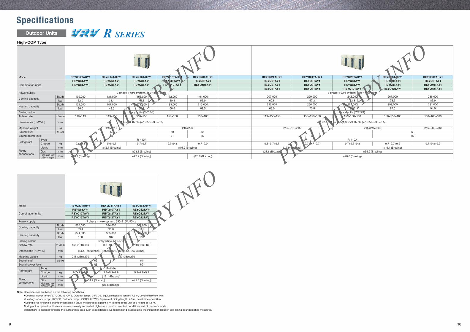
SpecificationsOutdoor Units
High-COP Type
Model
Combination units
Power supply
Cooling capacity
Heating capacity
Casing colourAir�ow rate
Dimensions (H×W×D)
Machine weightSound levelSound power level
RefrigerantTypeCharge
Piping connections
LiquidGasHigh and low pressure gas
Btu/h
Btu/hkW
kW
m³/min
mm
kgdB(A)
kgmmmm
mm
Model
Combination units
Power supply
Cooling capacity
Heating capacity
Casing colourAir�ow rate
Dimensions (H×W×D)
Machine weightSound levelSound power level
RefrigerantTypeCharge
Piping connections
LiquidGasHigh and low pressure gas
Btu/h
Btu/hkW
kW
m³/min
mm
kgdB(A)
kgmmmm
mm
Note: Speci�cations are based on the following conditions; •Cooling: Indoor temp.: 27°CDB, 19°CWB, Outdoor temp.: 35°CDB, Equivalent piping length: 7.5 m, Level difference: 0 m. •Heating: Indoor temp.: 20°CDB, Outdoor temp.: 7°CDB, 6°CWB, Equivalent piping length: 7.5 m, Level difference: 0 m. •Sound level: Anechoic chamber conversion value, measured at a point 1 m in front of the unit at a height of 1.5 m. During actual operation, these values are normally somewhat higher as a result of ambient conditions and oil recovery mode. When there is concern for noise the surrounding area such as residences, we recommend investigating the installation location and taking soundproo�ng measures.
REYQ32TAHY1REYQ8TAY1REYQ12TAY1REYQ12TAY1
REYQ34TAHY1REYQ10TAY1REYQ12TAY1REYQ12TAY1
REYQ36TAHY1REYQ12TAY1REYQ12TAY1REYQ12TAY1
3 phase 4-wire system, 380-415V, 50Hz
180+180+180
(1,657×930×765)+(1,657×930×765)+(1,657×930×765)
158+180+180 168+180+180
230+230+230215+230+23064638584
R-410A
φ19.1 (Brazing)
φ28.6 (Brazing)
Ivory white (5Y7.5/1)
345,000101
386,000113
324,00095.0
365,000107
305,00089.4
341,000100
9.9+9.9+9.99.8+9.9+9.99.7+9.9+9.9
φ34.9 (Brazing) φ41.3 (Brazing)
REYQ12TAHY1REYQ6TAY1REYQ6TAY1
109,00032.0
123,00036.0
131,00038.4
147,00043.0
153,00044.8
171,00050.0
Ivory white (5Y7.5/1)158+158
R-410A R-410A
φ28.6 (Brazing)
φ22.2 (Brazing)φ19.1 (Brazing) φ28.6 (Brazing) φ28.6 (Brazing)
158+180158+168 119+158+158 158+158+158 158+158+168 158+168+180158+158+180119+158
215+215
9.6+9.79.6+9.6 9.7+9.7
φ12.7 (Brazing)
215+2306160828180
215+230+230215+215+230215+215+21561
9.7+9.7+9.79.6+9.7+9.7
φ15.9 (Brazing)
9.7+9.7+9.8 9.7+9.7+9.9
φ19.1 (Brazing)φ28.6 (Brazing) φ34.9 (Brazing)
9.7+9.8+9.9
6282 83
9.7+9.8 9.7+9.9
φ15.9 (Brazing)
(1,657×930×765)+(1,657×930×765) (1,657×930×765)+(1,657×930×765)+(1,657×930×765)
119+119
59
Ivory white (5Y7.5/1)
172,00050.4
193,00056.5
191,00055.9
213,00062.5
—
REYQ14TAHY1REYQ6TAY1REYQ8TAY1
—
REYQ16TAHY1REYQ8TAY1REYQ8TAY1
—
REYQ18TAHY1REYQ8TAY1
REYQ10TAY1—
REYQ20TAHY1REYQ8TAY1
REYQ12TAY1—
REYQ22TAHY1REYQ6TAY1REYQ8TAY1REYQ8TAY1
REYQ24TAHY1REYQ8TAY1REYQ8TAY1REYQ8TAY1
REYQ26TAHY1REYQ8TAY1REYQ8TAY1REYQ10TAY1
3 phase 4-wire system, 380-415V, 50Hz3 phase 4-wire system, 380-415V, 50Hz
REYQ28TAHY1REYQ8TAY1REYQ8TAY1REYQ12TAY1
REYQ30TAHY1REYQ8TAY1
REYQ10TAY1REYQ12TAY1
207,000 229,000 248,000 267,000 286,00060.8 67.2 72.8 78.3 83.9
232,000 256,000 278,000 299,000 321,00068.0 75.0 81.5 87.5 94.0
PRELIMINARY IN
FO
PRELIMINARY IN
FO
PRELIMINARY IN
FO
11 12
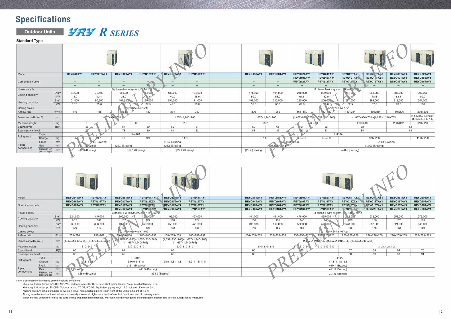
SpecificationsOutdoor Units
Standard Type
Note: Speci�cations are based on the following conditions; •Cooling: Indoor temp.: 27°CDB, 19°CWB, Outdoor temp.: 35°CDB, Equivalent piping length: 7.5 m, Level difference: 0 m. •Heating: Indoor temp.: 20°CDB, Outdoor temp.: 7°CDB, 6°CWB, Equivalent piping length: 7.5 m, Level difference: 0 m. •Sound level: Anechoic chamber conversion value, measured at a point 1 m in front of the unit at a height of 1.5 m. During actual operation, these values are normally somewhat higher as a result of ambient conditions and oil recovery mode. When there is concern for noise the surrounding area such as residences, we recommend investigating the installation location and taking soundproo�ng measures.
Model
Combination units
Power supply
Cooling capacity
Heating capacity
Casing colourAir�ow rate
Dimensions (H×W×D)
Machine weightSound levelSound power level
RefrigerantTypeCharge
Piping connections
LiquidGasHigh and low pressure gas
Btu/h
Btu/hkW
kW
m³/min
mm
kgdB(A)
kgmmmm
mm
Model
Combination units
Power supply
Cooling capacity
Heating capacity
Casing colourAir�ow rate
Dimensions (H×W×D)
Machine weightSound levelSound power level
RefrigerantTypeCharge
Piping connections
LiquidGasHigh and low pressure gas
Btu/h
Btu/hkW
kW
m³/min
mm
kgdB(A)
kgmmmm
mm
3 phase 4-wire system, 380-415V, 50Hz 3 phase 4-wire system, 380-415V, 50Hz
Ivory white (5Y7.5/1) Ivory white (5Y7.5/1)
324,000 345,000 365,000 382,000 403,000 423,000 444,000 461,000 478,000 495,000 512,000 532,000 553,000 573,00095.0 101 107 112 118 124
495,000 512,000 532,000 553,000 573,000 597,000 621,000 645,000145 150 156 162 168 175 182 189
362,000 386,000 409,000 427,000 450,000 471,000106 113 120 125 132 138
130 135 140 145 150 156 162 168
119 180 234 239 269226 168+180 180+180 180+234 180+239 180+226 239+239158 168
1,657×930×765 1,657×1,240×765 1,657×1,240×765 (1,657×930×765)+(1,657×930×765) (1,657×930×765)+(1,657×1,240×765)(1,657×1,240×765)+(1,657×1,240×765)
215 230 310 230+230 230+310 230+342 310+310
R-410A R-410A
56 57 59 60 6177 78 80 81 82
65 61 62 63 64
9.6 9.7 9.8 9.9 11.8 11.8 9.8+9.9 9.9+9.9 9.9+11.8
φ9.5 (Brazing) φ12.7 (Brazing)
34262
86 82 83 84 8583
φ15.9 (Brazing) φ19.1 (Brazing)φ19.1 (Brazing) φ22.2 (Brazing) φ28.6 (Brazing) φ28.6 (Brazing)
φ22.2 (Brazing)φ22.2 (Brazing)φ19.1 (Brazing)φ15.9 (Brazing) φ28.6 (Brazing)
φ 34.9 (Brazing)
— — REYQ14TAY1 REYQ16TAY1
REYQ34TAY1 REYQ36TAY1 REYQ38TAY1 REYQ40TAY1 REYQ42TAY1 REYQ44TAY1REYQ16TAY1 REYQ16TAY1 REYQ12TAY1 REYQ12TAY1 REYQ10TAY1 REYQ12TAY1REYQ18TAY1 REYQ20TAY1 REYQ12TAY1 REYQ12TAY1 REYQ16TAY1 REYQ16TAY1
REYQ16TAY1 REYQ16TAY1
REYQ46TAY1 REYQ48TAY1 REYQ50TAY1 REYQ52TAY1 REYQ54TAY1 REYQ56TAY1 REYQ58TAY1 REYQ60TAY1REYQ14TAY1 REYQ16TAY1 REYQ16TAY1 REYQ16TAY1 REYQ18TAY1 REYQ18TAY1 REYQ18TAY1 REYQ20TAY1REYQ16TAY1 REYQ16TAY1 REYQ16TAY1 REYQ18TAY1 REYQ18TAY1 REYQ18TAY1 REYQ20TAY1 REYQ20TAY1REYQ16TAY1 REYQ16TAY1 REYQ18TAY1 REYQ18TAY1 REYQ18TAY1 REYQ20TAY1 REYQ20TAY1 REYQ20TAY1
3 phase 4-wire system, 380-415V, 50Hz 3 phase 4-wire system, 380-415V, 50Hz
Ivory white (5Y7.5/1)Ivory white (5Y7.5/1)239+226 180+180+239180+180+234239+269 168+239+239 180+239+239 234+239+239 239+239+239 239+239+226 239+226+226 226+226+226 226+226+269 226+269+269 269+269+269
(1,657×1,240×765)+(1,657×1,240×765)(1,657×930×765)+(1,657×930×765)
+(1,657×1,240×765)(1,657×930×765)+(1,657×1,240×765)
+(1,657×1,240×765)(1,657×1,240×765)+(1,657×1,240×765)+(1,657×1,240×765)
310+310+310 310+342+342310+310+342 342+342+34265 6766 68 69 7086 8887 89 90 91
R-410AR-410A11.8+11.8+11.8
φ19.1 (Brazing)φ41.3 (Brazing)
φ34.9 (Brazing)
310+342 230+230+310 230+310+31065 66 64 6586 87 85 86
54,600 76,400 95,500 114,000 136,000 154,000 191,000 210,000 229,000 251,000 268,000 285,00016.0 22.4 28.0 33.5 40.0 45.0
215,000 235,000 256,000 281,000 299,000 319,00063.0 69.0 75.0 82.5 87.5 93.5
61,400 85,300 107,000 128,000 154,000 171,00018.0 25.0 31.5 37.5 45.0 50.0
56.0 61.5 67.0 73.5 78.5 83.5171,000
50.0191,000
56.0
307,00090.0
341,000100
REYQ6TAY1———
———
———
———
———
———
——— — — — — —
REYQ8TAY1 REYQ10TAY1 REYQ12TAY1 REYQ14TAY1 REYQ16TAY1 REYQ20TAY1 REYQ22TAY1 REYQ24TAY1 REYQ26TAY1 REYQ28TAY1 REYQ30TAY1REYQ10TAY1 REYQ12TAY1 REYQ12TAY1 REYQ12TAY1 REYQ12TAY1REYQ12TAY1 REYQ12TAY1 REYQ14TAY1 REYQ16TAY1 REYQ18TAY1
———
REYQ18TAY1
—
REYQ32TAY1REYQ16TAY1REYQ16TAY1
11.8+11.8
11.8+11.8 9.9+9.9+11.8 9.8+11.8+11.8 9.9+11.8+11.8
φ19.1 (Brazing)φ34.9 (Brazing) φ41.3 (Brazing)
φ28.6 (Brazing) φ34.9 (Brazing)
PRELIMINARY IN
FO
PRELIMINARY IN
FO
PRELIMINARY IN
FO
PRELIMINARY IN
FO

13 14
Memo
All rights reserved 04/18 AKc
•Speci�cations, designs and other content appearing in this brochure are current as of April 2018 but subject to change without notice.
1. Air conditioners should not be installed in areas where corrosive gases, such as acid gas or alkaline gas, are produced.2. If the outdoor unit is to be installed close to the sea shore, direct exposure to the sea breeze should be avoided. If you need to install the outdoor unit close to the sea shore, contact your local distributor.
Cautions on product corrosion
Ask a quali�ed installer or contractor to install this product. Do not try to install the product yourself. Improper installation can result in water or refrigerant leakage, electrical shock, �re or explosion.
Use only those parts and accessories supplied or speci�ed by Daikin. Ask a quali�ed installer or contractor to install those parts and accessories. Use of unauthorised parts and accessories or improper installation of parts and accessories can result in water or refrigerant leakage, electrical shock, �re or explosion.
Read the user's manual carefully before using this product. The user's manual provides important safety instructions and warnings. Be sure to follow these instructions and warnings.
If you have any enquiries, please contact your local importer, distributor and/or retailer.
PVTVAU1807Preview Brochure
Next generation VRV system featuringVRT now with Airside Control
VRV is a trade mark of Daikin Industries, Ltd.VRV Air Conditioning System is the world's �rst individual air conditioning system with variable refrigerant �ow control and was commercialised by Daikin in 1982.VRV is the trade mark of Daikin Industries, Ltd., which is derived from the technology we call "variable refrigerant volume."
Heat Recovery 50 HzHeat Pump 50 Hz