
NEXCOM International Mobile Computing Solutions...
30
NEXCOM International NEXCOM International Co., Ltd. Published April 2018 www.nexcom.com Mobile Computing Solutions Vehicle Mount Display VMD 3002 User Manual
Transcript of NEXCOM International Mobile Computing Solutions...
NEXCOM International
NEXCOM International Co., Ltd.Published April 2018 www.nexcom.com
Mobile Computing Solutions Vehicle Mount DisplayVMD 3002User Manual
Copyright © 2013 NEXCOM International Co., Ltd. All rights reserved ii VMD 3002 User Manual
Contents
PrefaceCopyright Notice .................................................................................... iiiDisclaimer .............................................................................................. iiiAcknowledgements ............................................................................... iiiRegulatory Compliance Statements ........................................................ iiiDeclaration of Conformity ...................................................................... iii
Warranty and RMANEXCOM Warranty Period ...................................................................... vNEXCOM Return Merchandise Authorization (RMA) ................................ v
Headquarters ....................................................................................... viGlobal Service Contact Information ........................................................ vi
Ordering Information
Chapter 1: Product IntroductionOverview ................................................................................................1Specifications ..........................................................................................2VMD 3002 Dimensions ...........................................................................3
Chapter 2: VMD 3002 Hardware FunctionalityFront Panel & Rear Panel Functions .........................................................4Back Panel & Pigtail Multi-IO Cable .........................................................5Cable Pinout Diagram .............................................................................6Pin Assignment .......................................................................................7
Chapter 3: Hardware InstallationAssembling the Stand .............................................................................8
Chapter 4: OSD FunctionMenu Structure of the Screen Adjustment...............................................9OSD Menu Tree .....................................................................................10OSD-PC Menu: Contrast, Brightness, Color Mode & Auto Config ..........11OSD-System Menu: Duration & Information ..........................................13OSD-Geometry Menu ...........................................................................14
Chapter 5: API of Controlling VMD 3002 - Initial SetupUpdating MCU Code ............................................................................18
Chapter 6: Table for MCU Protocol........................20
Contents
Preface
Copyright © 2013 NEXCOM International Co., Ltd. All Rights Reserved. VMD 3002 User Manualiii
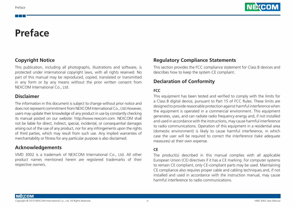
Copyright NoticeThis publication, including all photographs, illustrations and software, is protected under international copyright laws, with all rights reserved. No part of this manual may be reproduced, copied, translated or transmitted in any form or by any means without the prior written consent from NEXCOM International Co., Ltd.
DisclaimerThe information in this document is subject to change without prior notice and does not represent commitment from NEXCOM International Co., Ltd.However, users may update their knowledge of any product in use by constantly checking its manual posted on our website: http://www.nexcom.com. NEXCOM shall not be liable for direct, indirect, special, incidental, or consequential damages arising out of the use of any product, nor for any infringements upon the rights of third parties, which may result from such use. Any implied warranties of merchantability or fitness for any particular purpose is also disclaimed.
AcknowledgementsVMD 3002 is a trademark of NEXCOM International Co., Ltd. All other product names mentioned herein are registered trademarks of their respective owners.
Regulatory Compliance StatementsThis section provides the FCC compliance statement for Class B devices anddescribes how to keep the system CE compliant.
Declaration of Conformity
FCCThis equipment has been tested and verified to comply with the limits for a Class B digital device, pursuant to Part 15 of FCC Rules. These limits are designed to provide reasonable protection against harmful interference when the equipment is operated in a commercial environment. This equipment generates, uses, and can radiate radio frequency energy and, if not installed and used in accordance with the instructions, may cause harmful interference to radio communications. Operation of this equipment in a residential area (domestic environment) is likely to cause harmful interference, in which case the user will be required to correct the interference (take adequate measures) at their own expense.
CEThe product(s) described in this manual complies with all applicable European Union (CE) directives if it has a CE marking. For computer systems to remain CE compliant, only CE-compliant parts may be used. Maintaining CE compliance also requires proper cable and cabling techniques.and, if not installed and used in accordance with the instruction manual, may cause harmful interference to radio communications.
Preface
Preface
Copyright © 2013 NEXCOM International Co., Ltd. All Rights Reserved. VMD 3002 User Manualiv
RoHS Compliance
NEXCOM RoHS Environmental Policy and Status Update
NEXCOM is a global citizen for building the digital infrastructure. We are committed to providing green products and services, which are compliant with European Union RoHS (Restriction on Use of Hazardous Substance in Electronic Equipment) directive 2011/65/EU, to be your trusted green partner and to protect our environment. RoHS restricts the use of Lead (Pb) < 0.1% or 1,000ppm, Mercury (Hg) < 0.1% or 1,000ppm, Cadmium (Cd) < 0.01% or 100ppm, Hexavalent Chromium (Cr6+) < 0.1% or 1,000ppm, Polybrominated biphenyls (PBB) < 0.1% or 1,000ppm, and Polybrominated diphenyl Ethers (PBDE) < 0.1% or 1,000ppm.In order to meet the RoHS compliant directives, NEXCOM has established an engineering and manufacturing task force in to implement the introduction of green products. The task force will ensure that we follow the standard NEXCOM development procedure and that all the new RoHS components and new manufacturing processes maintain the highest industry quality levels for which NEXCOM are renowned.
How to Recognize NEXCOM RoHS ProductsFor existing products where there are non-RoHS and RoHS versions, the suffix “(LF)” will be added to the compliant product name.All new product models launched after January 2013 will be RoHS compliant. They will use the usual NEXCOM naming convention.
Installation RecommendationsEnsure you have a stable, clean working environment. Dust and dirt can get into components and cause a malfunction. Use containers to keep small components separated.
Adequate lighting and proper tools can prevent you from accidentally damaging the internal components. Most of the procedures that follow require only a few simple tools, including the following:
▪ A Philips screwdriver
▪ A flat-tipped screwdriver
▪ A grounding strap
▪ An anti-static pad
Using your fingers can disconnect most of the connections. It is recommended that you do not use needlenose pliers to disconnect connections as these can damage the soft metal or plastic parts of the connectors.
Handling Precautions ▪ Always disconnect the unit from the power outlet whenever you are
installing or fixing a component inside the chassis.
▪ If possible, always wear a grounded wrist strap when you are installing or fixing a component inside the chassis. Alternatively, discharge any static electricity by touching the bare metal chassis of the unit case, or the bare metal body of any other grounded appliance.
▪ Hold electronic circuit boards by the edges only. Do not touch the components on the board unless it is necessary to do so. Do not flex or stress the circuit board.
▪ Use the correct screws and do not overly tighten them.
▪ Keep the original packaging and static-protective bag in case the unit has to be returned.
Warranty and RMA
Copyright © 2013 NEXCOM International Co., Ltd. All Rights Reserved. VMD 3002 User Manualv
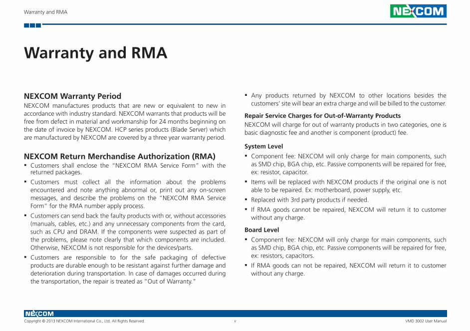
NEXCOM Warranty PeriodNEXCOM manufactures products that are new or equivalent to new in accordance with industry standard. NEXCOM warrants that products will be free from defect in material and workmanship for 24 months beginning on the date of invoice by NEXCOM. HCP series products (Blade Server) which are manufactured by NEXCOM are covered by a three year warranty period.
NEXCOM Return Merchandise Authorization (RMA) ▪ Customers shall enclose the “NEXCOM RMA Service Form” with the
returned packages.
▪ Customers must collect all the information about the problems encountered and note anything abnormal or, print out any on-screen messages, and describe the problems on the “NEXCOM RMA Service Form” for the RMA number apply process.
▪ Customers can send back the faulty products with or, without accessories (manuals, cables, etc.) and any unnecessary components from the card, such as CPU and DRAM. If the components were suspected as part of the problems, please note clearly that which components are included. Otherwise, NEXCOM is not responsible for the devices/parts.
▪ Customers are responsible to for the safe packaging of defective products are durable enough to be resistant against further damage and deterioration during transportation. In case of damages occurred during the transportation, the repair is treated as “Out of Warranty.”
▪ Any products returned by NEXCOM to other locations besides the customers’ site will bear an extra charge and will be billed to the customer.
Repair Service Charges for Out-of-Warranty ProductsNEXCOM will charge for out of warranty products in two categories, one is basic diagnostic fee and another is component (product) fee.
System Level
▪ Component fee: NEXCOM will only charge for main components, such as SMD chip, BGA chip, etc. Passive components will be repaired for free, ex: resistor, capacitor.
▪ Items will be replaced with NEXCOM products if the original one is not able to be repaired. Ex: motherboard, power supply, etc.
▪ Replaced with 3rd party products if needed.
▪ If RMA goods cannot be repaired, NEXCOM will return it to customer without any charge.
Board Level
▪ Component fee: NEXCOM will only charge for main components, such as SMD chip, BGA chip, etc. Passive components will be repaired for free, ex: resistors, capacitors.
▪ If RMA goods can not be repaired, NEXCOM will return it to customer without any charge.
Warranty and RMA
Warranty and RMA
Copyright © 2013 NEXCOM International Co., Ltd. All Rights Reserved. VMD 3002 User Manualvi
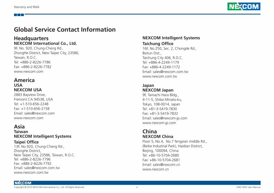
Global Service Contact InformationHeadquartersNEXCOM International Co., Ltd.9F, No. 920, Chung-Cheng Rd., ZhongHe District, New Taipei City, 23586, Taiwan, R.O.C.Tel: +886-2-8226-7786 Fax: +886-2-8226-7782 www.nexcom.com
AmericaUSANEXCOM USA2883 Bayview Drive, Fremont CA 94538, USA Tel: +1-510-656-2248 Fax: +1-510-656-2158Email: [email protected]
AsiaTaiwanNEXCOM Intelligent SystemsTaipei Office13F, No.920, Chung-Cheng Rd.,ZhongHe District,New Taipei City, 23586, Taiwan, R.O.C.Tel: +886-2-8226-7796Fax: +886-2-8226-7792Email: [email protected]
NEXCOM Intelligent SystemsTaichung Office16F, No.250, Sec. 2, Chongde Rd., Beitun Dist., Taichung City 406, R.O.C. Tel: +886-4-2249-1179Fax: +886-4-2249-1172Email: [email protected]
JapanNEXCOM Japan9F, Tamachi Hara Bldg., 4-11-5, Shiba Minato-ku, Tokyo, 108-0014, Japan Tel: +81-3-5419-7830Fax: +81-3-5419-7832Email: [email protected]
ChinaNEXCOM ChinaFloor 5, No.4, No.7 fengxian middle Rd.,(Beike Industrial Park), Haidian District,Beijing, 100094, ChinaTel: +86-10-5704-2680Fax: +86-10-5704-2681Email: [email protected] www.nexcom.cn

Warranty and RMA
Copyright © 2013 NEXCOM International Co., Ltd. All Rights Reserved. VMD 3002 User Manualvii
EuropeUnited KingdomNEXCOM EUROPE10 Vincent Avenue, Crownhill Business Centre,Milton Keynes, BuckinghamshireMK8 0AB, United Kingdom Tel: +44-1908-267121Fax: +44-1908-262042Email: [email protected]
ItalyNEXCOM ITALIA S.r.lVia Lanino 42, 21047 Saronno (VA), ItaliaTel: +39 02 9628 0333Fax: +39 02 9625 570Email: [email protected]
NEXCOM ShanghaiRoom 603/604, Huiyinmingzun Plaza Bldg., 1, No.609, Yunlin East Rd., Shanghai, 200333, ChinaTel: +86-21-5278-5868Fax: +86-21-3251-6358Email: [email protected] www.nexcom.cn
NEXCOM Surveillance Technology Corp.Room202, Building B,the GuangMing Industrial Zone Zhonghua Rd.,Minzhi Street, Longhua District,Shenzhen 518131, ChinaTel: +86-755-8364-7768 Fax: +86-755-8364-7738Email: [email protected] www.nexcom.cn
NEXCOM United System ServiceHui Yin Ming Zun Building Room 1108, Building No. 11, 599 Yunling Road, Putuo District, Shanghai, 200062, ChinaTel: +86-21-6125-8282Fax: +86-21-6125-8281Email: [email protected]

Ordering Information
Copyright © 2013 NEXCOM International Co., Ltd. All Rights Reserved. VMD 3002 User Manualviii
Ordering InformationThe following provides ordering information for VMD 3002.
▪ VMD 3002-BS (P/N: 10VD0100002X2) 10.4” XGA vehicle mount display with touch screen, VGA and CVBS Interfaces ▪ Bundle Accessories
Part Number Description
6030000043X00 External 50-pin Multi-I/O Cable, L=1120mm
602DCD0779X00 Driver CD

Copyright © 2013 NEXCOM International Co., Ltd. All Rights Reserved. VMD 3002 User Manual1
Chapter 1: Product Introduction
OverviewVMD 3002 is a robust 10.4-inch TFT LCD monitor with enhanced brightness, projected capacitive touchscreen, and high performance loud speaker. It is designed with a single cable to consolidate power, display, and other control signal to ease the installation and secure the connection. It also features four analog video inputs to feed the real time video from the rear view cameras to the display. VMD 3002 mechanical design is compliant with IP65. With the 1000nits ultra high brightness display and adaptive brightness control, it is an ideal solution for in-vehicle and outdoor
Chapter 1: Product Introduction
Copyright © 2013 NEXCOM International Co., Ltd. All Rights Reserved. VMD 3002 User Manual2
Chapter 1: Product Introduction
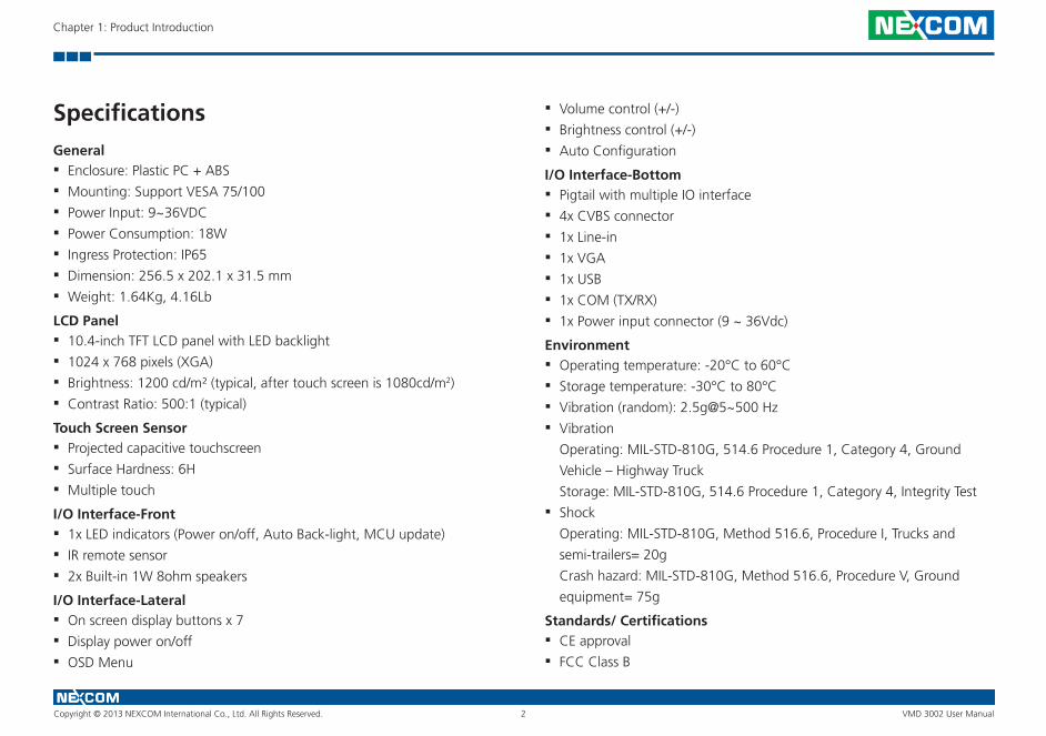
SpecificationsGeneral ▪ Enclosure: Plastic PC + ABS
▪ Mounting: Support VESA 75/100
▪ Power Input: 9~36VDC
▪ Power Consumption: 18W
▪ Ingress Protection: IP65
▪ Dimension: 256.5 x 202.1 x 31.5 mm
▪ Weight: 1.64Kg, 4.16Lb
LCD Panel ▪ 10.4-inch TFT LCD panel with LED backlight
▪ 1024 x 768 pixels (XGA)
▪ Brightness: 1200 cd/m² (typical, after touch screen is 1080cd/m2)
▪ Contrast Ratio: 500:1 (typical)
Touch Screen Sensor ▪ Projected capacitive touchscreen
▪ Surface Hardness: 6H
▪ Multiple touch
I/O Interface-Front ▪ 1x LED indicators (Power on/off, Auto Back-light, MCU update)
▪ IR remote sensor
▪ 2x Built-in 1W 8ohm speakers
I/O Interface-Lateral ▪ On screen display buttons x 7
▪ Display power on/off
▪ OSD Menu
▪ Volume control (+/-)
▪ Brightness control (+/-)
▪ Auto Configuration
I/O Interface-Bottom ▪ Pigtail with multiple IO interface
▪ 4x CVBS connector
▪ 1x Line-in
▪ 1x VGA
▪ 1x USB
▪ 1x COM (TX/RX)
▪ 1x Power input connector (9 ~ 36Vdc)
Environment ▪ Operating temperature: -20°C to 60°C
▪ Storage temperature: -30°C to 80°C
▪ Vibration (random): 2.5g@5~500 Hz
▪ Vibration
Operating: MIL-STD-810G, 514.6 Procedure 1, Category 4, Ground
Vehicle – Highway Truck
Storage: MIL-STD-810G, 514.6 Procedure 1, Category 4, Integrity Test
▪ Shock
Operating: MIL-STD-810G, Method 516.6, Procedure I, Trucks and
semi-trailers= 20g
Crash hazard: MIL-STD-810G, Method 516.6, Procedure V, Ground
equipment= 75g
Standards/ Certifications ▪ CE approval
▪ FCC Class B
Copyright © 2013 NEXCOM International Co., Ltd. All Rights Reserved. VMD 3002 User Manual3
Chapter 1: Product Introduction
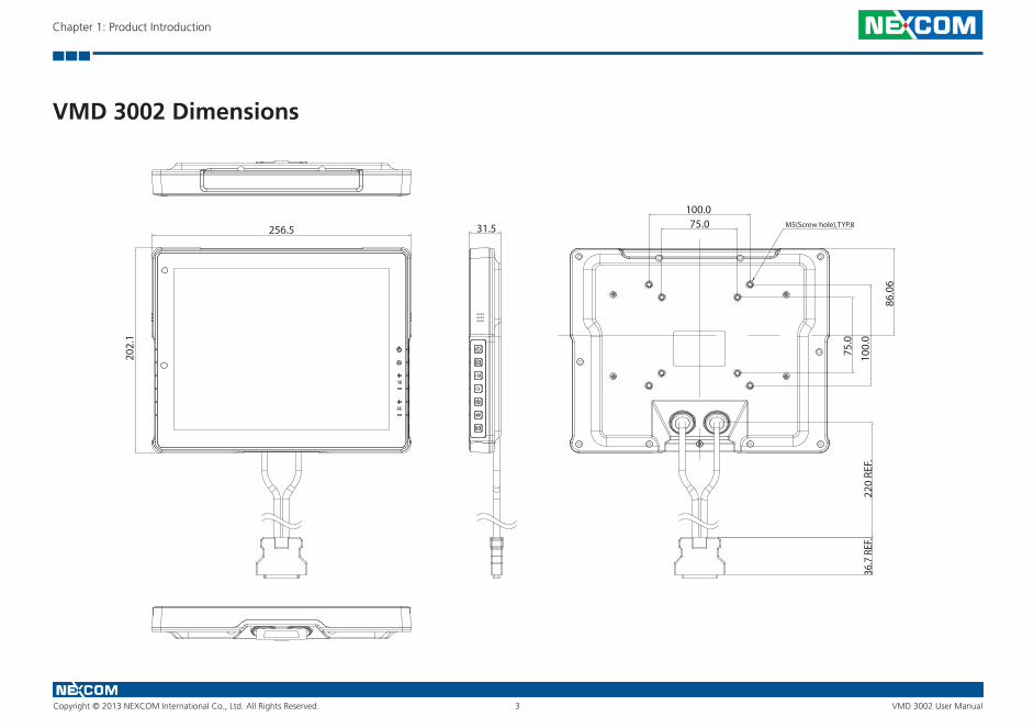
VMD 3002 Dimensions
256.5
202.
1
31.5 75.0100.0
75.0
100.
0
M5(Screw hole),TYP.8
86.0
6
220
REF.
36.7
REF
.
Copyright © 2013 NEXCOM International Co., Ltd. All Rights Reserved. VMD 3002 User Manual
Chapter 2: VMD Series Hardware Functionality
4
Chapter 2: VMD 3002 Hardware Functionality
3
2
1
5
6
7
8
4
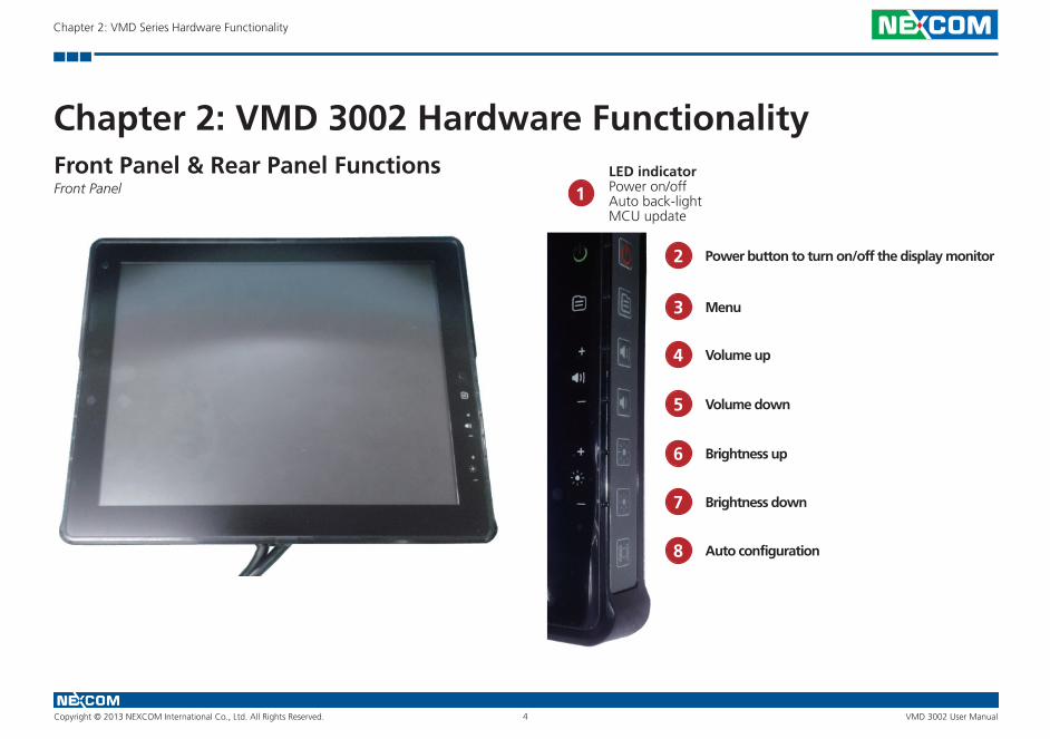
Front Panel & Rear Panel FunctionsFront Panel
LED indicatorPower on/off Auto back-lightMCU update
Power button to turn on/off the display monitor
Menu
Volume up
Volume down
Brightness up
Brightness down
Auto configuration
Copyright © 2013 NEXCOM International Co., Ltd. All Rights Reserved. VMD 3002 User Manual
Chapter 2: VMD Series Hardware Functionality
5
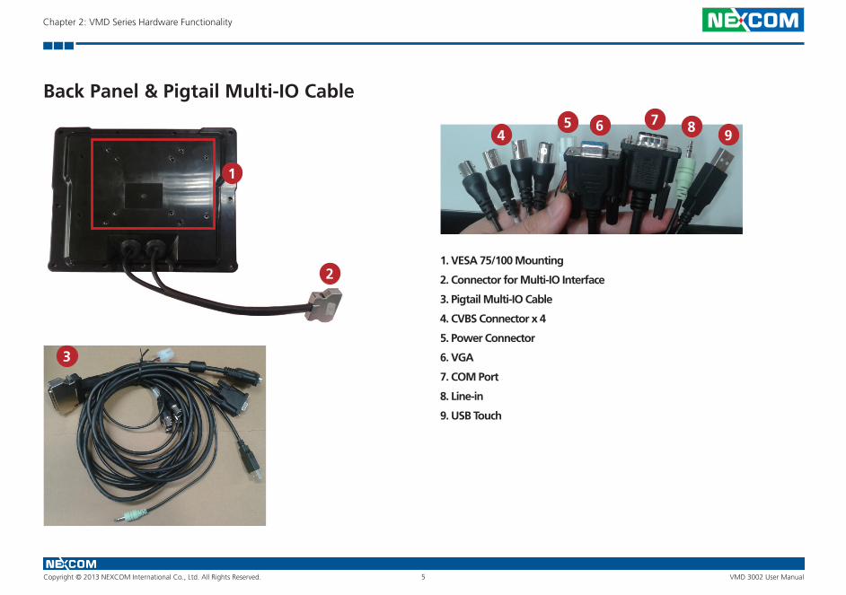
Back Panel & Pigtail Multi-IO Cable
1
2
3
45 6 7 8 9
1. VESA 75/100 Mounting
2. Connector for Multi-IO Interface
3. Pigtail Multi-IO Cable
4. CVBS Connector x 4
5. Power Connector
6. VGA
7. COM Port
8. Line-in
9. USB Touch

Copyright © 2013 NEXCOM International Co., Ltd. All Rights Reserved. VMD 3002 User Manual
Chapter 2: VMD Series Hardware Functionality
6
Cable Pinout Diagram
Copyright © 2013 NEXCOM International Co., Ltd. All Rights Reserved. VMD 3002 User Manual
Chapter 2: VMD Series Hardware Functionality
7
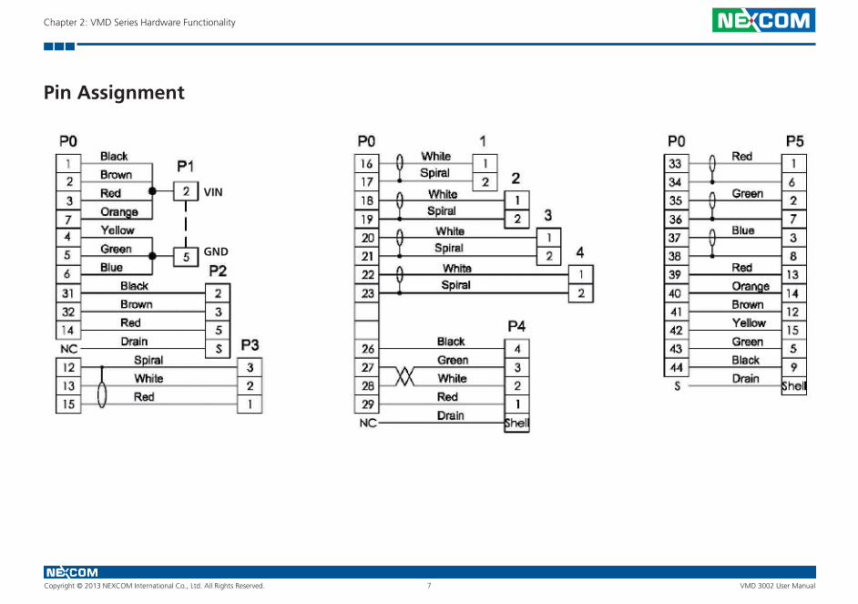
Pin Assignment
VIN
GND
Copyright © 2013 NEXCOM International Co., Ltd. All Rights Reserved.
Chapter 3: Hardware Installation
8 VMD 3002 User Manual
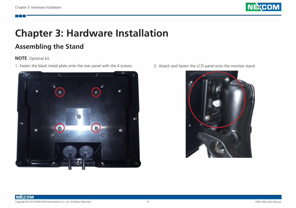
Chapter 3: Hardware InstallationAssembling the Stand
NOTE: Optional kit.
1. Fasten the black metal plate onto the rear panel with the 4 screws. 2. Attach and fasten the LCD panel onto the monitor stand.

Copyright © 2013 NEXCOM International Co., Ltd. All Rights Reserved. VMD 3002 User Manual9
Chapter 4: OSD Function
Chapter 4: OSD Function
Menu Structure of the Screen Adjustment
Power On (Green Light) – Press oncePower Off (Blind) – Press onceAuto Mode (Orange Light) – Press twice
OSD Menu / Exit
Move (Left) – Main OSD MenuAdjustment (+) – Sub OSD MenuEnter to Sub Menu
Move (Right) – Main OSD MenuAdjustment (-) – Sub OSD MenuEnter to Sub Menu
Select (up)
Select (down)
Auto-Adjustment
PC
Select
Contrast 50
Brightness 100
COLOR MODE
Auto Config
Factory Reset
Move Exit
PC
►
►
►
► ▲▲ MENU
Copyright © 2013 NEXCOM International Co., Ltd. All Rights Reserved. VMD 3002 User Manual10
Chapter 4: OSD Function
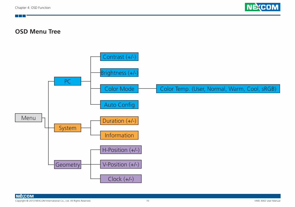
Menu
PCColor Temp. (User, Normal, Warm, Cool, sRGB)
Auto Config
Duration (+/-)
Information
H-Position (+/-)
V-Position (+/-)
Clock (+/-)
Color Mode
Brightness (+/-)
Contrast (+/-)
System
Geometry
OSD Menu Tree

Copyright © 2013 NEXCOM International Co., Ltd. All Rights Reserved. VMD 3002 User Manual11
Chapter 4: OSD Function
OSD-PC Menu: Contrast, Brightness, Color Mode & Auto Config
Menu Description
Auto Config Automatically adjusts every parameter
Menu Description
Brightness Adjusts the brightness of the display
Contrast Adjusts the contrast of the display
PC
Select
Contrast 50
Brightness 90
COLOR MODE
Auto Config
Contrast 50
Brightness 90
Move
Adjust
Adjust
Exit
Exit
Exit
PC
►
►
►
►
►
►
►
▲▲ MENU
MENU
MENU

Copyright © 2013 NEXCOM International Co., Ltd. All Rights Reserved. VMD 3002 User Manual12
Chapter 4: OSD Function
Menu Description
Color Temp Adjusts the color temperature of the display
PC
Select
User - R 128
User - G 128
User - B 128
Move Exit
PC
►
► ▲▲ MENU
Color Temp. User
►
►
Copyright © 2013 NEXCOM International Co., Ltd. All Rights Reserved. VMD 3002 User Manual13
Chapter 4: OSD Function
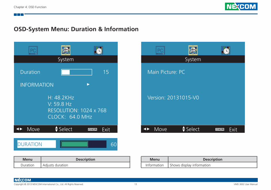
OSD-System Menu: Duration & Information
Menu Description
Duration Adjusts duration
Menu Description
Information Shows display information
System System
Select Select
Duration 15
INFORMATION
H: 48.2KHz V: 59.8 Hz RESOLUTION: 1024 x 768 CLOCK: 64.0 MHz
Main Picture: PC
Version: 20131015-V0
Move MoveExit Exit
PC PC
►
► ►
► ►▲ ▲▲ ▲MENU MENU
DURATION 60

Copyright © 2013 NEXCOM International Co., Ltd. All Rights Reserved. VMD 3002 User Manual14
Chapter 4: OSD Function
OSD-Geometry Menu
Menu Description
H-Position Moves the position of the OSD Menu in horizontal direction
V-Position Moves the position of the OSD Menu in vertical direction
Clock Adjusts the clock of display
Geometry
Select
H-Position 50
V-Position 39
Clock 50
Move Exit
PC
►
► ▲▲ MENU
Geometry
PC
H-Position
Clock
V-Position
50
50
42
Copyright © 2013 NEXCOM International Co., Ltd. All Rights Reserved. VMD 3002 User Manual15
Chapter 5: API of Controlling VMD 3002
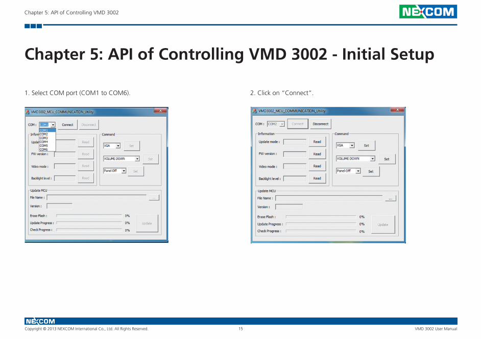
Chapter 5: API of Controlling VMD 3002 - Initial Setup
1. Select COM port (COM1 to COM6). 2. Click on “Connect”.
Copyright © 2013 NEXCOM International Co., Ltd. All Rights Reserved. VMD 3002 User Manual16
Chapter 5: API of Controlling VMD 3002
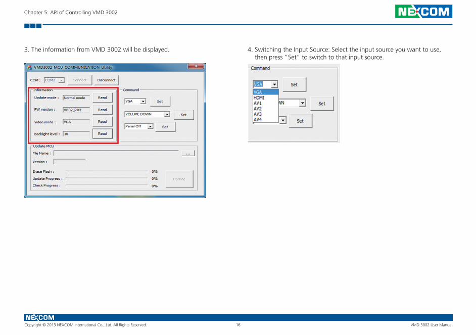
3. The information from VMD 3002 will be displayed. 4. Switching the Input Source: Select the input source you want to use, then press “Set” to switch to that input source.

Copyright © 2013 NEXCOM International Co., Ltd. All Rights Reserved. VMD 3002 User Manual17
Chapter 5: API of Controlling VMD 3002
5. Controlling the Function from Lateral Membrane Key: Select the item that you want to control, then press “Set” to apply the function.
6. On/Off Panel: Select “Panel Off” then press “Set” to turn off panel backlight. Select “Panel On” then press “Set” to turn on panel backlight.

Copyright © 2013 NEXCOM International Co., Ltd. All Rights Reserved. VMD 3002 User Manual18
Chapter 5: API of Controlling VMD 3002
Updating MCU Code
1. Locate the firmware file and click on “Open”. 2. Click on “Update” once the correct firmware file is chosen.

Copyright © 2013 NEXCOM International Co., Ltd. All Rights Reserved. VMD 3002 User Manual19
Chapter 5: API of Controlling VMD 3002
3. A system pop-up message will appear once the update is completed. 4. Click on the “Read” button next to the FW version textbox to check the new firmware version.

Copyright © 2013 NEXCOM International Co., Ltd. All Rights Reserved. VMD 3002 User Manual20
Chapter 6: Table for MCU Protocol
Chapter 6: Table for MCU Protocol
Frame-based Protocol Command List
Start Code 0xF1
Command 1 Bytes
Data N Byte, N = 0~19
End Code 0xF2
Name Code
ReturnEraseFlash 0x11
ReturnWriteFlash 0x13
ReturnReadFlash 0x15
ReturnProgramState 0x21
ReturnFlashState 0x25
ReturnBSLInfo 0x31
ReturnReboot 0x37
ReturnUpdateMode 0x41
ReturnRequestUpdate 0x43
ReturnInvalidCommand 0x7F
Name Code
EraseFlash 0x10
WriteFlash 0x12
ReadFlash 0x14
ReadProgramState 0x20
Flash Unlock 0x24
ReadBSLInfo 0x30
IsRequestReboot 0x36
ReadUpdateMode 0x40
IsRequestUpdate 0x42
Copyright © 2013 NEXCOM International Co., Ltd. All Rights Reserved. VMD 3002 User Manual21
Chapter 6: Table for MCU Protocol
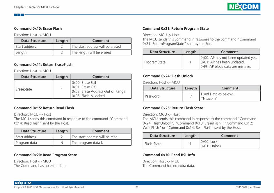
Command 0x10: Erase Flash
Command 0x11: ReturnEraseFlash
Command 0x20: Read Program State
Direction: Host -> MCU
Direction: Host -> MCU
Direction: Host -> MCUThe Command has no extra data.
Data Structure Length Comment
Start address 2 The start address will be erased
Length 2 The length will be erased
Data Structure Length Comment
EraseState 1
0x00: Erase Fail0x01: Erase OK0x02: Erase Address Out of Range0x03: Flash is Locked
Command 0x15: Return Read Flash
Direction: MCU -> HostThe MCU sends this command in response to the command “Command 0x14: ReadFlash” sent by the Host.
Data Structure Length Comment
Start address 2 The start address will be read
Program data N The program data N
Command 0x21: Return Program State
Direction: MCU -> HostThe MCU sends this command in response to the command “Command 0x21: ReturnProgramState” sent by the Soc.
Data Structure Length Comment
ProgramState 10x00: AP has not been updated yet.0x01: AP has been updated.0xFF: AP block data are mistake.
Command 0x24: Flash Unlock
Direction: Host -> MCU
Data Structure Length Comment
Password 7Fixed Data as below:“Nexcom”
Command 0x25: Return Flash State
Direction: MCU -> HostThe MCU sends this command in response to the command “Command 0x24: FlashUnlock”, “Command 0x10: EraseFlash”, “Command 0x12: WriteFlash” or “Command 0x14: ReadFlash” sent by the Host.
Data Structure Length Comment
Flash State 10x00: Lock0x01: Unlock
Command 0x30: Read BSL Info
Direction: Host -> MCUThe Command has no extra data.
Copyright © 2013 NEXCOM International Co., Ltd. All Rights Reserved. VMD 3002 User Manual22
Chapter 6: Table for MCU Protocol
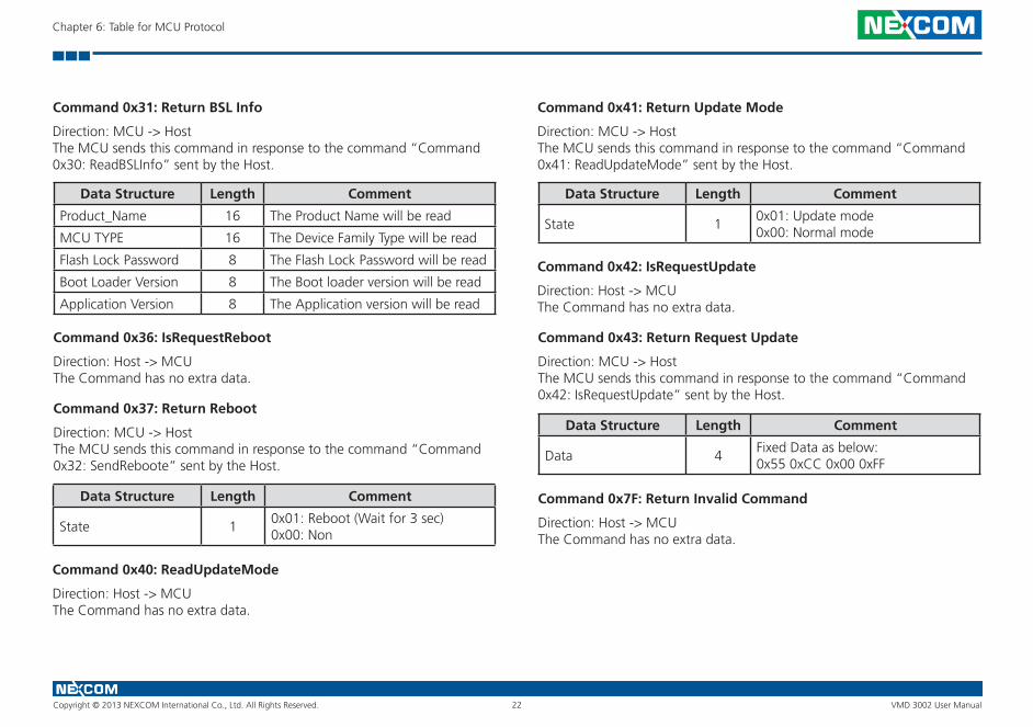
Command 0x37: Return Reboot
Command 0x41: Return Update ModeCommand 0x31: Return BSL Info
Direction: MCU -> HostThe MCU sends this command in response to the command “Command 0x32: SendReboote” sent by the Host.
Direction: MCU -> HostThe MCU sends this command in response to the command “Command 0x41: ReadUpdateMode” sent by the Host.
Direction: MCU -> HostThe MCU sends this command in response to the command “Command 0x30: ReadBSLInfo” sent by the Host.
Data Structure Length Comment
State 10x01: Reboot (Wait for 3 sec)0x00: Non
Data Structure Length Comment
State 10x01: Update mode0x00: Normal mode
Data Structure Length Comment
Product_Name 16 The Product Name will be read
MCU TYPE 16 The Device Family Type will be read
Flash Lock Password 8 The Flash Lock Password will be read
Boot Loader Version 8 The Boot loader version will be read
Application Version 8 The Application version will be read
Command 0x40: ReadUpdateMode
Command 0x42: IsRequestUpdate
Command 0x36: IsRequestReboot
Direction: Host -> MCUThe Command has no extra data.
Direction: Host -> MCUThe Command has no extra data.
Direction: Host -> MCUThe Command has no extra data.
Command 0x43: Return Request Update
Direction: MCU -> HostThe MCU sends this command in response to the command “Command 0x42: IsRequestUpdate” sent by the Host.
Data Structure Length Comment
Data 4Fixed Data as below:0x55 0xCC 0x00 0xFF
Command 0x7F: Return Invalid Command
Direction: Host -> MCUThe Command has no extra data.